EP3799153A1 - Output electrode assembly and battery module - Google Patents
Output electrode assembly and battery module Download PDFInfo
- Publication number
- EP3799153A1 EP3799153A1 EP19905311.7A EP19905311A EP3799153A1 EP 3799153 A1 EP3799153 A1 EP 3799153A1 EP 19905311 A EP19905311 A EP 19905311A EP 3799153 A1 EP3799153 A1 EP 3799153A1
- Authority
- EP
- European Patent Office
- Prior art keywords
- output electrode
- wall
- electrode assembly
- connector
- partition wall
- Prior art date
- Legal status (The legal status is an assumption and is not a legal conclusion. Google has not performed a legal analysis and makes no representation as to the accuracy of the status listed.)
- Granted
Links
Images


Classifications
-
- H—ELECTRICITY
- H01—ELECTRIC ELEMENTS
- H01M—PROCESSES OR MEANS, e.g. BATTERIES, FOR THE DIRECT CONVERSION OF CHEMICAL ENERGY INTO ELECTRICAL ENERGY
- H01M50/00—Constructional details or processes of manufacture of the non-active parts of electrochemical cells other than fuel cells, e.g. hybrid cells
- H01M50/50—Current conducting connections for cells or batteries
- H01M50/531—Electrode connections inside a battery casing
-
- H—ELECTRICITY
- H01—ELECTRIC ELEMENTS
- H01M—PROCESSES OR MEANS, e.g. BATTERIES, FOR THE DIRECT CONVERSION OF CHEMICAL ENERGY INTO ELECTRICAL ENERGY
- H01M50/00—Constructional details or processes of manufacture of the non-active parts of electrochemical cells other than fuel cells, e.g. hybrid cells
- H01M50/10—Primary casings; Jackets or wrappings
- H01M50/172—Arrangements of electric connectors penetrating the casing
- H01M50/174—Arrangements of electric connectors penetrating the casing adapted for the shape of the cells
-
- H—ELECTRICITY
- H01—ELECTRIC ELEMENTS
- H01M—PROCESSES OR MEANS, e.g. BATTERIES, FOR THE DIRECT CONVERSION OF CHEMICAL ENERGY INTO ELECTRICAL ENERGY
- H01M50/00—Constructional details or processes of manufacture of the non-active parts of electrochemical cells other than fuel cells, e.g. hybrid cells
- H01M50/20—Mountings; Secondary casings or frames; Racks, modules or packs; Suspension devices; Shock absorbers; Transport or carrying devices; Holders
- H01M50/204—Racks, modules or packs for multiple batteries or multiple cells
-
- H—ELECTRICITY
- H01—ELECTRIC ELEMENTS
- H01M—PROCESSES OR MEANS, e.g. BATTERIES, FOR THE DIRECT CONVERSION OF CHEMICAL ENERGY INTO ELECTRICAL ENERGY
- H01M50/00—Constructional details or processes of manufacture of the non-active parts of electrochemical cells other than fuel cells, e.g. hybrid cells
- H01M50/20—Mountings; Secondary casings or frames; Racks, modules or packs; Suspension devices; Shock absorbers; Transport or carrying devices; Holders
- H01M50/204—Racks, modules or packs for multiple batteries or multiple cells
- H01M50/207—Racks, modules or packs for multiple batteries or multiple cells characterised by their shape
-
- H—ELECTRICITY
- H01—ELECTRIC ELEMENTS
- H01M—PROCESSES OR MEANS, e.g. BATTERIES, FOR THE DIRECT CONVERSION OF CHEMICAL ENERGY INTO ELECTRICAL ENERGY
- H01M50/00—Constructional details or processes of manufacture of the non-active parts of electrochemical cells other than fuel cells, e.g. hybrid cells
- H01M50/20—Mountings; Secondary casings or frames; Racks, modules or packs; Suspension devices; Shock absorbers; Transport or carrying devices; Holders
- H01M50/204—Racks, modules or packs for multiple batteries or multiple cells
- H01M50/207—Racks, modules or packs for multiple batteries or multiple cells characterised by their shape
- H01M50/209—Racks, modules or packs for multiple batteries or multiple cells characterised by their shape adapted for prismatic or rectangular cells
-
- H—ELECTRICITY
- H01—ELECTRIC ELEMENTS
- H01M—PROCESSES OR MEANS, e.g. BATTERIES, FOR THE DIRECT CONVERSION OF CHEMICAL ENERGY INTO ELECTRICAL ENERGY
- H01M50/00—Constructional details or processes of manufacture of the non-active parts of electrochemical cells other than fuel cells, e.g. hybrid cells
- H01M50/20—Mountings; Secondary casings or frames; Racks, modules or packs; Suspension devices; Shock absorbers; Transport or carrying devices; Holders
- H01M50/244—Secondary casings; Racks; Suspension devices; Carrying devices; Holders characterised by their mounting method
-
- H—ELECTRICITY
- H01—ELECTRIC ELEMENTS
- H01M—PROCESSES OR MEANS, e.g. BATTERIES, FOR THE DIRECT CONVERSION OF CHEMICAL ENERGY INTO ELECTRICAL ENERGY
- H01M50/00—Constructional details or processes of manufacture of the non-active parts of electrochemical cells other than fuel cells, e.g. hybrid cells
- H01M50/20—Mountings; Secondary casings or frames; Racks, modules or packs; Suspension devices; Shock absorbers; Transport or carrying devices; Holders
- H01M50/262—Mountings; Secondary casings or frames; Racks, modules or packs; Suspension devices; Shock absorbers; Transport or carrying devices; Holders with fastening means, e.g. locks
- H01M50/264—Mountings; Secondary casings or frames; Racks, modules or packs; Suspension devices; Shock absorbers; Transport or carrying devices; Holders with fastening means, e.g. locks for cells or batteries, e.g. straps, tie rods or peripheral frames
-
- H—ELECTRICITY
- H01—ELECTRIC ELEMENTS
- H01M—PROCESSES OR MEANS, e.g. BATTERIES, FOR THE DIRECT CONVERSION OF CHEMICAL ENERGY INTO ELECTRICAL ENERGY
- H01M50/00—Constructional details or processes of manufacture of the non-active parts of electrochemical cells other than fuel cells, e.g. hybrid cells
- H01M50/20—Mountings; Secondary casings or frames; Racks, modules or packs; Suspension devices; Shock absorbers; Transport or carrying devices; Holders
- H01M50/284—Mountings; Secondary casings or frames; Racks, modules or packs; Suspension devices; Shock absorbers; Transport or carrying devices; Holders with incorporated circuit boards, e.g. printed circuit boards [PCB]
-
- H—ELECTRICITY
- H01—ELECTRIC ELEMENTS
- H01M—PROCESSES OR MEANS, e.g. BATTERIES, FOR THE DIRECT CONVERSION OF CHEMICAL ENERGY INTO ELECTRICAL ENERGY
- H01M50/00—Constructional details or processes of manufacture of the non-active parts of electrochemical cells other than fuel cells, e.g. hybrid cells
- H01M50/20—Mountings; Secondary casings or frames; Racks, modules or packs; Suspension devices; Shock absorbers; Transport or carrying devices; Holders
- H01M50/284—Mountings; Secondary casings or frames; Racks, modules or packs; Suspension devices; Shock absorbers; Transport or carrying devices; Holders with incorporated circuit boards, e.g. printed circuit boards [PCB]
- H01M50/287—Fixing of circuit boards to lids or covers
-
- H—ELECTRICITY
- H01—ELECTRIC ELEMENTS
- H01M—PROCESSES OR MEANS, e.g. BATTERIES, FOR THE DIRECT CONVERSION OF CHEMICAL ENERGY INTO ELECTRICAL ENERGY
- H01M50/00—Constructional details or processes of manufacture of the non-active parts of electrochemical cells other than fuel cells, e.g. hybrid cells
- H01M50/50—Current conducting connections for cells or batteries
-
- H—ELECTRICITY
- H01—ELECTRIC ELEMENTS
- H01M—PROCESSES OR MEANS, e.g. BATTERIES, FOR THE DIRECT CONVERSION OF CHEMICAL ENERGY INTO ELECTRICAL ENERGY
- H01M50/00—Constructional details or processes of manufacture of the non-active parts of electrochemical cells other than fuel cells, e.g. hybrid cells
- H01M50/50—Current conducting connections for cells or batteries
- H01M50/502—Interconnectors for connecting terminals of adjacent batteries; Interconnectors for connecting cells outside a battery casing
- H01M50/519—Interconnectors for connecting terminals of adjacent batteries; Interconnectors for connecting cells outside a battery casing comprising printed circuit boards [PCB]
-
- H—ELECTRICITY
- H01—ELECTRIC ELEMENTS
- H01M—PROCESSES OR MEANS, e.g. BATTERIES, FOR THE DIRECT CONVERSION OF CHEMICAL ENERGY INTO ELECTRICAL ENERGY
- H01M10/00—Secondary cells; Manufacture thereof
- H01M10/42—Methods or arrangements for servicing or maintenance of secondary cells or secondary half-cells
- H01M10/425—Structural combination with electronic components, e.g. electronic circuits integrated to the outside of the casing
-
- Y—GENERAL TAGGING OF NEW TECHNOLOGICAL DEVELOPMENTS; GENERAL TAGGING OF CROSS-SECTIONAL TECHNOLOGIES SPANNING OVER SEVERAL SECTIONS OF THE IPC; TECHNICAL SUBJECTS COVERED BY FORMER USPC CROSS-REFERENCE ART COLLECTIONS [XRACs] AND DIGESTS
- Y02—TECHNOLOGIES OR APPLICATIONS FOR MITIGATION OR ADAPTATION AGAINST CLIMATE CHANGE
- Y02E—REDUCTION OF GREENHOUSE GAS [GHG] EMISSIONS, RELATED TO ENERGY GENERATION, TRANSMISSION OR DISTRIBUTION
- Y02E60/00—Enabling technologies; Technologies with a potential or indirect contribution to GHG emissions mitigation
- Y02E60/10—Energy storage using batteries
Definitions
- This application relates to the field of battery technologies, and in particular, to an output electrode assembly and a battery module.
- Battery modules usually include a plurality of batteries arranged side by side, a plurality of connection bars connecting the plurality of batteries in series and parallel, an FPC for collecting battery temperature and voltage, a connector (a low-voltage interface of the battery module) that electrically connects the FPC to a control system and an output electrode connecting sheet (a high-voltage interface of the battery module) that electrically connects the plurality of batteries to an external apparatus.
- a traditional battery module is typically provided with two independent sets of components (namely, an output electrode base and a connector mounting base) to mount the output electrode connecting sheet and the connector respectively.
- the two sets of components need to be separately processed and formed, and then assembled with the output electrode connecting sheet and the connector respectively, which leads to low assembly efficiency of the battery module and is not conducive to the integration of the battery module.
- an objective of this application is to provide an output electrode assembly and a battery module.
- the output electrode assembly has few components and a high degree of integration, which improves the assembly efficiency and integration of the battery module.
- this application provides an output electrode assembly and a battery module, where the output electrode assembly includes a circuit board, a connector, an output electrode connecting sheet and a fastening base.
- the connector is disposed at one end of the circuit board in a longitudinal direction, and the output electrode connecting sheet is spaced apart from the connector in a transverse direction.
- the fastening base has a partition wall located between the output electrode connecting sheet and the connector; a first mounting portion formed on one side of the partition wall in the transverse direction, where the connector is fixedly mounted to the first mounting portion; and a second mounting portion formed on the other side of the partition wall in the transverse direction, where the output electrode connecting sheet is fixedly mounted to the second mounting portion.
- the first mounting portion has a first bottom wall connected to the partition wall and extending in the transverse direction; a first front wall connected to the partition wall and the first bottom wall; and a first rear wall spaced apart from the first front wall in the longitudinal direction and connected to the partition wall and the first bottom wall.
- the connector is accommodated in a housing cavity formed by the first bottom wall, the first front wall, the first rear wall and the partition wall.
- the first mounting portion further has an opening formed in the first front wall and/or the first rear wall; and an elastic clasp cantilevered in the opening and griping the connector together with the first rear wall and/or the first front wall.
- the fastening base further has a transitional connection wall connected to the partition wall and the first rear wall; and a supporting portion connected to the transitional connection wall and extending in the longitudinal direction, where the circuit board is supported by the supporting portion.
- the circuit board is provided with position locking holes.
- the fastening base further has position locking posts disposed on the supporting portion, where the position locking posts are fitted with the position locking holes to fasten the circuit board.
- the one end of the circuit board has a first bending portion; a transition portion; and a second bending portion, which forms a U-shaped structure together with the transition portion and the first bending portion.
- the output electrode assembly further includes a reinforcing plate disposed between the second bending portion and the first bending portion.
- the connector is located on one side of the second bending portion in the longitudinal direction.
- the second mounting portion has a second bottom wall connected to the partition wall and extending in the transverse direction; a side wall connected to the second bottom wall and spaced apart from the partition wall in the transverse direction; and a second rear wall connected to the second bottom wall and spaced apart from the partition wall in the transverse direction.
- the output electrode connecting sheet is partly located between the second rear wall and the partition wall, and partly accommodated in the housing cavity formed by the second bottom wall, the side wall, the second rear wall and the partition wall.
- the output electrode assembly further includes an insert embedded in the second bottom wall, where the output electrode connecting sheet is fixed to the insert.
- the second mounting part further has a second front wall connected to the partition wall and the second bottom wall.
- This application further provides a battery module, including a plurality of batteries and the foregoing output electrode assembly, where the output electrode assembly is disposed above the plurality of batteries.
- the fastening base is provided with the first mounting portion and the second mounting portion to respectively mount the connector and the output electrode connecting sheet (that is, the connector and the output electrode connecting sheet are both fixed onto the same fastening base)
- the fastening base has functions of both an output electrode base and a connector mounting base in a traditional battery module. Therefore, the output electrode assembly has a small quantity of components and high degree of integration, improving the assembly efficiency and integration of the battery module.
- output electrode assembly 143 second mounting portion 11. circuit board 1431. second bottom wall 111. first bending portion 1432. side wall 112. transition portion 1433. second rear wall 113. second bending portion 1434. second front wall 114. position locking hole 144. transitional connection wall 12. connector 145. support portion 13. output electrode connecting sheet 146. position locking post 15. reinforcing plate 14. fastening base 16. insert 141. partition wall 2. battery 142. first mounting portion 3. electrical connection sheet 1421. first bottom wall 4. end plate 1422. first front wall X. transverse direction 1423. first rear wall Y. longitudinal direction 1424. opening Z. up-down direction 1425. elastic clasp
- connection may be a fixed connection, a detachable connection, or an integrated connection, and may be an electrical connection or signal a connection; and a “connection” may be a direct connection, or an indirect connection through an intermediate medium.
- a battery module of this application includes an output electrode assembly 1, a plurality of batteries 2, a plurality of electrical connection sheets 3, two end plates 4, and a control system (not shown).
- the output electrode assembly 1 is disposed above the plurality of batteries 2 and includes a circuit board 11, a connector 12, an output electrode connecting sheet 13, a fastening base 14, a reinforcing plate 15 and an insert 16.
- the circuit board 11 is provided with a circuit for collecting temperature and voltage of the battery 2.
- the circuit board 11 may be a flexible printed circuit board (Flexible Printed Circuit, FPC for short).
- the connector 12 is electrically connected to the circuit in the circuit board 11 and the control system, to implement information interaction between the circuit board 11 and the control system. Referring to FIG. 2 , the connector 12 is disposed at one end of the circuit board 11 in a longitudinal direction Y and spaced apart from the output electrode connecting sheet 13 in a transverse direction X, where the connector 12 and the output electrode connecting sheet 13 are both fixed onto the fastening base 14.
- the fastening base 14 has a partition wall 141 located between the output electrode connecting sheet 13 and the connector 12; a first mounting portion 142 formed on one side of the partition wall 141 in the transverse direction X, where the connector 12 is fixedly mounted to the first mounting portion 142; and a second mounting portion 143 formed on the other side of the partition wall 141 in the transverse direction X, where the output electrode connecting sheet 13 is fixedly mounted to the second mounting portion 143.
- the fastening base 14 is provided with the first mounting portion 142 and the second mounting portion 143 to respectively mount the connector 12 and the output electrode connecting sheet 13 (that is, the connector 12 and the output electrode connecting sheet 13 are both fixed onto the same fastening base), the fastening base 14 has functions of both an output electrode base and a connector mounting base in a traditional battery module. Therefore, the output electrode assembly 1 has a small quantity of components and high degree of integration, improving the assembly efficiency and integration of the battery module.
- the first mounting portion 142 has a first bottom wall 1421 connected to the partition wall 141 and extending in the transverse direction X; a first front wall 1422 connected to the partition wall 141 and the first bottom wall 1421; and a first rear wall 1423 spaced apart from the first front wall 1422 in the longitudinal direction Y and connected to the partition wall 141 and the first bottom wall 1421.
- the connector 12 is accommodated in a housing cavity formed by the first bottom wall 1421, the first front wall 1422, the first rear wall 1423 and the partition wall 141.
- the first mounting portion 142 further has an opening 1424 formed in the first front wall1422 and/or the first rear wall 1423; and an elastic clasp 1425 cantilevered in the opening 1424.
- the elastic clasp 1425 can grip the connector 12 together with the first rear wall 1423 and/or the first front wall 1422, thereby avoiding the problem of poor contact caused by shaking of the connector 12 during use of the battery module.
- the fastening base 14 further has a transitional connection wall 144 connected to the partition wall 141 and the first rear wall 1423; and a supporting portion 145 connected to the transitional connecting wall 144 and extending in the longitudinal direction Y, where the circuit board 11 is supported by the supporting portion 145.
- the support portion 145 of the fastening base 14 can be used to support the circuit board 11. Therefore, the battery module does not need an additional structure for fixing the circuit board 11, thereby reducing the components of the battery module and further improving the assembly efficiency and integration of the battery module.
- the circuit board 11 is provided with position locking holes 114.
- the fastening base 14 further has position locking posts 146 disposed on the supporting portion 145, where the position locking posts 146 are fitted with the position locking holes 114 to fasten the circuit board 11.
- the assembly can be completed quickly, thereby improving the assembly efficiency of the battery module.
- the one end of the circuit board 11 has a first bending portion 111; a transition portion 112; and a second bending portion 113, which forms a U-shaped structure together with the transition portion 112 and the first bending portion 111.
- the reinforcing plate 15 is disposed between the second bending portion 113 and the first bending portion 111, and the connector 12 is located at one side of the second bending portion 113 in the longitudinal direction Y and is connected to the second bending portion 113.
- disposition of the reinforcing plate 15 enhances the strength of the second bending portion 113 and facilitates connection between the connector 12 and the second bending portion 113.
- the second mounting portion 143 has a second bottom wall 1431 connected to the partition wall 141 and extending in the transverse direction X; a side wall 1432 connected to the second bottom wall 1431 and spaced apart from the partition wall 141 in the transverse direction X; and a second rear wall 1433 connected to the second bottom wall 1431 and spaced apart from the partition wall 141 in the transverse direction X.
- the output electrode connecting sheet 13 is partly located between the second rear wall 1433 and the partition wall 141, and partly accommodated in the housing cavity formed by the second bottom wall 1431, the side wall 1432, the second rear wall 1433 and the partition wall 141.
- the insert 16 is embedded in the second bottom wall 1431 of the second mounting portion 143, and the output electrode connecting sheet 13 is fixed to the insert 16 by a fastener.
- the second mounting portion 143 further has a second front wall 1434 connected to the partition wall 141 and the second bottom wall 1431.
- the second front wall 1434 and the second rear wall 433 together define a mounting position of the output electrode connecting sheet 13.
- the plurality of electrical connection sheets 3 are fixedly disposed on the support portion 145 of the fastening base 14 of the output pole assembly 1, where each electrical connection sheet 3 is electrically connected to a corresponding battery 2, so as to realize the electrical connection between all the batteries 2.
- the two end plates 4 are respectively disposed at two ends of the plurality of batteries 2 in the longitudinal direction Y to firmly grip the plurality of batteries 2.
Landscapes
- Chemical & Material Sciences (AREA)
- Chemical Kinetics & Catalysis (AREA)
- Electrochemistry (AREA)
- General Chemical & Material Sciences (AREA)
- Battery Mounting, Suspending (AREA)
- Connection Of Batteries Or Terminals (AREA)
Abstract
Description
- This application relates to the field of battery technologies, and in particular, to an output electrode assembly and a battery module.
- Battery modules usually include a plurality of batteries arranged side by side, a plurality of connection bars connecting the plurality of batteries in series and parallel, an FPC for collecting battery temperature and voltage, a connector (a low-voltage interface of the battery module) that electrically connects the FPC to a control system and an output electrode connecting sheet (a high-voltage interface of the battery module) that electrically connects the plurality of batteries to an external apparatus. At present, in order to fix the connector and the output electrode connecting sheet, a traditional battery module is typically provided with two independent sets of components (namely, an output electrode base and a connector mounting base) to mount the output electrode connecting sheet and the connector respectively. The two sets of components need to be separately processed and formed, and then assembled with the output electrode connecting sheet and the connector respectively, which leads to low assembly efficiency of the battery module and is not conducive to the integration of the battery module.
- In view of the problem in the background, an objective of this application is to provide an output electrode assembly and a battery module. The output electrode assembly has few components and a high degree of integration, which improves the assembly efficiency and integration of the battery module.
- To achieve the foregoing objective, this application provides an output electrode assembly and a battery module, where the output electrode assembly includes a circuit board, a connector, an output electrode connecting sheet and a fastening base. The connector is disposed at one end of the circuit board in a longitudinal direction, and the output electrode connecting sheet is spaced apart from the connector in a transverse direction. The fastening base has a partition wall located between the output electrode connecting sheet and the connector; a first mounting portion formed on one side of the partition wall in the transverse direction, where the connector is fixedly mounted to the first mounting portion; and a second mounting portion formed on the other side of the partition wall in the transverse direction, where the output electrode connecting sheet is fixedly mounted to the second mounting portion.
- The first mounting portion has a first bottom wall connected to the partition wall and extending in the transverse direction; a first front wall connected to the partition wall and the first bottom wall; and a first rear wall spaced apart from the first front wall in the longitudinal direction and connected to the partition wall and the first bottom wall. The connector is accommodated in a housing cavity formed by the first bottom wall, the first front wall, the first rear wall and the partition wall.
- The first mounting portion further has an opening formed in the first front wall and/or the first rear wall; and an elastic clasp cantilevered in the opening and griping the connector together with the first rear wall and/or the first front wall.
- The fastening base further has a transitional connection wall connected to the partition wall and the first rear wall; and a supporting portion connected to the transitional connection wall and extending in the longitudinal direction, where the circuit board is supported by the supporting portion.
- The circuit board is provided with position locking holes. The fastening base further has position locking posts disposed on the supporting portion, where the position locking posts are fitted with the position locking holes to fasten the circuit board.
- The one end of the circuit board has a first bending portion; a transition portion; and a second bending portion, which forms a U-shaped structure together with the transition portion and the first bending portion. The output electrode assembly further includes a reinforcing plate disposed between the second bending portion and the first bending portion. The connector is located on one side of the second bending portion in the longitudinal direction.
- The second mounting portion has a second bottom wall connected to the partition wall and extending in the transverse direction; a side wall connected to the second bottom wall and spaced apart from the partition wall in the transverse direction; and a second rear wall connected to the second bottom wall and spaced apart from the partition wall in the transverse direction. The output electrode connecting sheet is partly located between the second rear wall and the partition wall, and partly accommodated in the housing cavity formed by the second bottom wall, the side wall, the second rear wall and the partition wall.
- The output electrode assembly further includes an insert embedded in the second bottom wall, where the output electrode connecting sheet is fixed to the insert.
- The second mounting part further has a second front wall connected to the partition wall and the second bottom wall.
- This application further provides a battery module, including a plurality of batteries and the foregoing output electrode assembly, where the output electrode assembly is disposed above the plurality of batteries.
- Beneficial effects of this application are as follows:
As the fastening base is provided with the first mounting portion and the second mounting portion to respectively mount the connector and the output electrode connecting sheet (that is, the connector and the output electrode connecting sheet are both fixed onto the same fastening base), the fastening base has functions of both an output electrode base and a connector mounting base in a traditional battery module. Therefore, the output electrode assembly has a small quantity of components and high degree of integration, improving the assembly efficiency and integration of the battery module. -
-
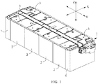
FIG. 1 is a perspective view of a battery module in this application; -
FIG. 2 is a perspective view of an output electrode assembly of a battery module; -
FIG. 3 is an exploded view ofFIG. 2 ; and -
FIG. 4 is an enlarged view of a circled part inFIG. 3 . - Reference signs are described as follows:
1. output electrode assembly 143. second mounting portion 11. circuit board 1431. second bottom wall 111. first bending portion 1432. side wall 112. transition portion 1433. second rear wall 113. second bending portion 1434. second front wall 114. position locking hole 144. transitional connection wall 12. connector 145. support portion 13. output electrode connecting sheet 146. position locking post 15. reinforcing plate 14. fastening base 16. insert 141. partition wall 2. battery 142. first mounting portion 3. electrical connection sheet 1421. first bottom wall 4. end plate 1422. first front wall X. transverse direction 1423. first rear wall Y. longitudinal direction 1424. opening Z. up- down direction 1425. elastic clasp - To make the objectives, technical solutions, and advantages of this application more comprehensible, the following describes this application in detail with reference to embodiments and accompanying drawings. It should be understood that the specific embodiments described herein are merely used to explain this application but are not intended to limit this application.
- In the descriptions of this application, unless otherwise specified and defined explicitly, the terms "first" and "second" are merely intended for a purpose of description, and should not be understood as any indication or implication of relative importance; the term "plurality of' indicates two or more (including two); and unless otherwise specified and defined explicitly, the terms "connection" and "fixing" should be understood in their general senses. For example, a "connection" may be a fixed connection, a detachable connection, or an integrated connection, and may be an electrical connection or signal a connection; and a "connection" may be a direct connection, or an indirect connection through an intermediate medium. A person of ordinary skill in the art can understand specific meanings of these terms in this application based on specific situations.
- In the descriptions of the specification, it should be understood that the positional terms such as "above", "under (or bottom)", "front", and "rear" described in the embodiments of this application are described as seen from the angles shown in the accompanying drawings, and should not be understood as limitations on the embodiments of this application. In addition, in the context, it should also be understood that when an element is referred to as being "above" or "under" another element, the element can either be directly connected "above" or "under" the another element, or be indirectly connected "above" or "under" the another element through an intermediate element. This application is hereinafter further described in detail with reference to specific embodiments and the accompanying drawings.
- Referring to
FIG. 1 , a battery module of this application includes an output electrode assembly 1, a plurality ofbatteries 2, a plurality of electrical connection sheets 3, two end plates 4, and a control system (not shown). - Referring to
FIG. 2 to FIG. 4 , the output electrode assembly 1 is disposed above the plurality ofbatteries 2 and includes acircuit board 11, aconnector 12, an outputelectrode connecting sheet 13, afastening base 14, a reinforcingplate 15 and aninsert 16. - The
circuit board 11 is provided with a circuit for collecting temperature and voltage of thebattery 2. Thecircuit board 11 may be a flexible printed circuit board (Flexible Printed Circuit, FPC for short). - The
connector 12 is electrically connected to the circuit in thecircuit board 11 and the control system, to implement information interaction between thecircuit board 11 and the control system. Referring toFIG. 2 , theconnector 12 is disposed at one end of thecircuit board 11 in a longitudinal direction Y and spaced apart from the outputelectrode connecting sheet 13 in a transverse direction X, where theconnector 12 and the outputelectrode connecting sheet 13 are both fixed onto thefastening base 14. - Referring to
FIG. 3 andFIG. 4 , thefastening base 14 has apartition wall 141 located between the outputelectrode connecting sheet 13 and theconnector 12; a first mountingportion 142 formed on one side of thepartition wall 141 in the transverse direction X, where theconnector 12 is fixedly mounted to the first mountingportion 142; and a second mountingportion 143 formed on the other side of thepartition wall 141 in the transverse direction X, where the outputelectrode connecting sheet 13 is fixedly mounted to the second mountingportion 143. - As the
fastening base 14 is provided with the first mountingportion 142 and the second mountingportion 143 to respectively mount theconnector 12 and the output electrode connecting sheet 13 (that is, theconnector 12 and the outputelectrode connecting sheet 13 are both fixed onto the same fastening base), thefastening base 14 has functions of both an output electrode base and a connector mounting base in a traditional battery module. Therefore, the output electrode assembly 1 has a small quantity of components and high degree of integration, improving the assembly efficiency and integration of the battery module. - Referring to
FIG. 3 andFIG. 4 , the first mountingportion 142 has afirst bottom wall 1421 connected to thepartition wall 141 and extending in the transverse direction X; a firstfront wall 1422 connected to thepartition wall 141 and thefirst bottom wall 1421; and a firstrear wall 1423 spaced apart from the firstfront wall 1422 in the longitudinal direction Y and connected to thepartition wall 141 and the first bottom wall 1421.Theconnector 12 is accommodated in a housing cavity formed by thefirst bottom wall 1421, the firstfront wall 1422, the firstrear wall 1423 and thepartition wall 141. - Referring to
FIG. 3 andFIG. 4 , the first mountingportion 142 further has anopening 1424 formed in the first front wall1422 and/or the firstrear wall 1423; and anelastic clasp 1425 cantilevered in the opening 1424.When theconnector 12 is disposed in the housing cavity formed by thefirst bottom wall 1421, the firstfront wall 1422, the firstrear wall 1423 and thepartition wall 141, theelastic clasp 1425 can grip theconnector 12 together with the firstrear wall 1423 and/or the firstfront wall 1422, thereby avoiding the problem of poor contact caused by shaking of theconnector 12 during use of the battery module. - Referring to
FIG. 2 to FIG. 4 , thefastening base 14 further has atransitional connection wall 144 connected to thepartition wall 141 and the firstrear wall 1423; and a supportingportion 145 connected to the transitional connectingwall 144 and extending in the longitudinal direction Y, where thecircuit board 11 is supported by the supporting portion 145.Thesupport portion 145 of thefastening base 14 can be used to support thecircuit board 11. Therefore, the battery module does not need an additional structure for fixing thecircuit board 11, thereby reducing the components of the battery module and further improving the assembly efficiency and integration of the battery module. - Referring to
FIG. 2 andFIG. 3 , thecircuit board 11 is provided with position locking holes 114.Thefastening base 14 further hasposition locking posts 146 disposed on the supportingportion 145, where theposition locking posts 146 are fitted with theposition locking holes 114 to fasten thecircuit board 11. During an assembly process of the output electrode assembly 1, based on the positioning and cooperation of theposition locking holes 114 and theposition locking posts 146, the assembly can be completed quickly, thereby improving the assembly efficiency of the battery module. - Referring to
FIG. 2 , the one end of thecircuit board 11 has a first bending portion 111; a transition portion 112; and a second bending portion 113, which forms a U-shaped structure together with the transition portion 112 and the first bending portion 111.The reinforcingplate 15 is disposed between the second bending portion 113 and the first bending portion 111, and theconnector 12 is located at one side of the second bending portion 113 in the longitudinal direction Y and is connected to the second bending portion 113.Herein, disposition of the reinforcingplate 15 enhances the strength of the second bending portion 113 and facilitates connection between theconnector 12 and the second bending portion 113. - Referring to
FIG. 3 andFIG. 4 , the second mountingportion 143 has asecond bottom wall 1431 connected to thepartition wall 141 and extending in the transverse direction X; aside wall 1432 connected to thesecond bottom wall 1431 and spaced apart from thepartition wall 141 in the transverse direction X; and a secondrear wall 1433 connected to thesecond bottom wall 1431 and spaced apart from thepartition wall 141 in the transverse direction X. The outputelectrode connecting sheet 13 is partly located between the secondrear wall 1433 and thepartition wall 141, and partly accommodated in the housing cavity formed by thesecond bottom wall 1431, theside wall 1432, the secondrear wall 1433 and the partition wall 141.Theinsert 16 is embedded in thesecond bottom wall 1431 of the second mountingportion 143, and the outputelectrode connecting sheet 13 is fixed to theinsert 16 by a fastener. - Referring to
FIG. 3 andFIG. 4 , the second mountingportion 143 further has a secondfront wall 1434 connected to thepartition wall 141 and the second bottom wall 1431.The secondfront wall 1434 and the second rear wall 433 together define a mounting position of the outputelectrode connecting sheet 13. - Referring to
FIG. 1 , the plurality of electrical connection sheets 3 are fixedly disposed on thesupport portion 145 of thefastening base 14 of the output pole assembly 1, where each electrical connection sheet 3 is electrically connected to acorresponding battery 2, so as to realize the electrical connection between all thebatteries 2. - Referring to
FIG. 1 , the two end plates 4 are respectively disposed at two ends of the plurality ofbatteries 2 in the longitudinal direction Y to firmly grip the plurality ofbatteries 2.
Claims (10)
- An output electrode assembly (1), comprising:a circuit board (11);a connector (12), disposed at one end of the circuit board (11) in a longitudinal direction (Y);an output electrode connecting sheet (13), spaced apart from the connector (12) in a transverse direction(X); anda fastening base (14), having a partition wall (141) located between the output electrode connecting sheet (13) and the connector (12); a first mounting portion (142) formed on one side of the partition wall (141) in the transverse direction (X), wherein the connector (12) is fixedly mounted to the first mounting portion (142); and a second mounting portion (143) formed on the other side of the partition wall (141) in the transverse direction (X), wherein the output electrode connecting sheet (13) is fixedly mounted to the second mounting portion (143).
- The output electrode assembly (1) according to claim 1, wherein
the first mounting portion (142) has a first bottom wall (1421) connected to the partition wall (141) and extending in the transverse direction (X); a first front wall (1422) connected to the partition wall (141) and the first bottom wall (1421); and a first rear wall (1423) spaced apart from the first front wall (1422) in the longitudinal direction (Y) and connected to the partition wall (141) and the first bottom wall (1421); and
the connector (12) is accommodated in a housing cavity formed by the first bottom wall (1421), the first front wall (1422), the first rear wall (1423) and the partition wall (141). - The output electrode assembly (1) according to claim 2, wherein the first mounting portion (142) further has an opening (1424) formed in the first front wall (1422) and/or the first rear wall (1423); and an elastic clasp (1425) cantilevered in the opening (1424) and griping the connector (12) together with the first rear wall (1423) and/or the first front wall (1422).
- The output electrode assembly (1) according to claim 2, wherein the fastening base (14) further has a transitional connection wall (144) connected to the partition wall (141) and the first rear wall (1423); and a supporting portion (145) connected to the transitional connecting wall (144) and extending in the longitudinal direction (Y), wherein the circuit board (11) is supported by the supporting portion (145).
- The output electrode assembly (1) according to claim 4, wherein
the circuit board (11) is provided with position locking holes (114); and
the fastening base (14) further has position locking posts (146) disposed on the supporting portion (145), wherein the position locking posts (146) are fitted with the position locking holes (114) to fasten the circuit board (11). - The output electrode assembly (1) according to claim 4, wherein
the one end of the circuit board (11) has a first bending portion (111); a transition portion (112); and a second bending portion (113), which forms a U-shaped structure together with the transition portion (112) and the first bending portion (111);
the output electrode assembly (1) further comprises a reinforcing plate (15) disposed between the second bending portion (113) and the first bending portion (111); and
the connector (12) is located on one side of the second bending part (113) in the longitudinal direction (Y). - The output electrode assembly (1) according to claim 1, wherein
the second mounting portion (143) has a second bottom wall (1431) connected to the partition wall (141) and extending in the transverse direction (X); a side wall (1432) connected to the second bottom wall (1431) and spaced apart from the partition wall (141) in the transverse direction (X); and a second rear wall (1433) connected to the second bottom wall (1431) and spaced apart from the partition wall (141) in the transverse direction (X); and
the output electrode connecting sheet (13) is partly located between the second rear wall (1433) and the partition wall (141), and partly accommodated in the housing cavity form formed by the second bottom wall (1431), the side wall (1432), the second rear wall (1433) and the partition wall (141). - The output electrode assembly (1) according to claim 7, wherein the output electrode assembly (1) further comprises an insert (16) embedded in the second bottom wall (1431), wherein the output electrode connecting sheet (13) is fixed to the insert (16).
- The output electrode assembly (1) according to claim 7, wherein the second mounting portion (143) further has a second front wall (1434) connected to the partition wall (141) and the second bottom wall (1431).
- A battery module, comprising a plurality of batteries (2) and the output electrode assembly (1) according to any one of claims 1 to 9, wherein the output electrode assembly (1) is disposed above the plurality of batteries (2).
Applications Claiming Priority (2)
| Application Number | Priority Date | Filing Date | Title |
|---|---|---|---|
| CN201822168790.0U CN209104222U (en) | 2018-12-23 | 2018-12-23 | Output pole assembly and battery module |
| PCT/CN2019/124358 WO2020135029A1 (en) | 2018-12-23 | 2019-12-10 | Output electrode assembly and battery module |
Publications (3)
| Publication Number | Publication Date |
|---|---|
| EP3799153A1 true EP3799153A1 (en) | 2021-03-31 |
| EP3799153A4 EP3799153A4 (en) | 2021-10-06 |
| EP3799153B1 EP3799153B1 (en) | 2022-06-15 |
Family
ID=67163157
Family Applications (1)
| Application Number | Title | Priority Date | Filing Date |
|---|---|---|---|
| EP19905311.7A Active EP3799153B1 (en) | 2018-12-23 | 2019-12-10 | Output electrode assembly and battery module |
Country Status (5)
| Country | Link |
|---|---|
| US (1) | US11417936B2 (en) |
| EP (1) | EP3799153B1 (en) |
| CN (1) | CN209104222U (en) |
| ES (1) | ES2922315T3 (en) |
| WO (1) | WO2020135029A1 (en) |
Families Citing this family (18)
| Publication number | Priority date | Publication date | Assignee | Title |
|---|---|---|---|---|
| CN209104222U (en) * | 2018-12-23 | 2019-07-12 | 宁德时代新能源科技股份有限公司 | Output pole assembly and battery module |
| CN210073989U (en) * | 2019-08-23 | 2020-02-14 | 宁德时代新能源科技股份有限公司 | battery module |
| CN211404602U (en) * | 2020-03-27 | 2020-09-01 | 中航锂电(洛阳)有限公司 | Laminate polymer battery module |
| CN113889713B (en) | 2020-07-03 | 2024-10-25 | 莫仕连接器(成都)有限公司 | Battery connection module |
| CN114122627B (en) | 2020-08-27 | 2024-08-09 | 莫仕连接器(成都)有限公司 | Battery connection module |
| CN111969154B (en) * | 2020-09-22 | 2025-12-30 | 宁德新能源科技有限公司 | Electrochemical devices and drones |
| US12525637B2 (en) | 2022-03-23 | 2026-01-13 | Ford Global Technologies, Llc | Traction battery pack assembling method |
| US12275298B2 (en) | 2022-03-23 | 2025-04-15 | Ford Global Technologies, Llc | Traction battery packs with cell-to-pack battery systems housed within irregularly shaped enclosures |
| US12374750B2 (en) | 2022-03-23 | 2025-07-29 | Ford Global Technologies, Llc | Traction battery pack assembling method |
| US12230826B2 (en) | 2022-03-23 | 2025-02-18 | Ford Global Technologies, Llc | Methods for assembling traction battery packs |
| US12506215B2 (en) | 2022-03-23 | 2025-12-23 | Ford Global Technologies, Llc | Enclosure cover attachment configurations for traction battery packs with cell-to-pack battery systems |
| US12424695B2 (en) | 2022-03-23 | 2025-09-23 | Ford Global Technologies, Llc | Retention assemblies for traction battery packs with cell-to-pack battery systems |
| US12567642B2 (en) | 2022-03-23 | 2026-03-03 | Ford Global Technologies, Llc | Shim systems for traction battery packs |
| US12603373B2 (en) | 2022-03-23 | 2026-04-14 | Ford Global Technologies, Llc | Traction battery pack assembling method |
| US12479327B2 (en) | 2022-03-23 | 2025-11-25 | Ford Global Technologies, Llc | Traction battery pack cell stack removal method and battery pack assembly |
| CN116526047A (en) * | 2023-05-31 | 2023-08-01 | 惠州亿纬锂能股份有限公司 | Output electrode base and battery pack |
| CN220628165U (en) * | 2023-08-25 | 2024-03-19 | 惠州亿纬锂能股份有限公司 | FPC acquisition device and battery module |
| CN121172361A (en) * | 2025-11-20 | 2025-12-19 | 宁德时代新能源科技股份有限公司 | Battery device and electricity utilization device |
Family Cites Families (11)
| Publication number | Priority date | Publication date | Assignee | Title |
|---|---|---|---|---|
| US20100248029A1 (en) * | 2009-01-07 | 2010-09-30 | A123 Systems, Inc. | Methods of welding battery terminals |
| JP5537111B2 (en) * | 2009-09-30 | 2014-07-02 | 株式会社東芝 | Secondary battery device |
| JP2013105522A (en) * | 2011-11-10 | 2013-05-30 | Auto Network Gijutsu Kenkyusho:Kk | Battery wiring module |
| US9831482B2 (en) * | 2013-09-06 | 2017-11-28 | Johnson Controls Technology Company | Battery module lid system and method |
| US11394086B2 (en) * | 2017-09-27 | 2022-07-19 | Kabushiki Kaisha Toshiba | Battery module and connection member |
| CN207818730U (en) * | 2018-01-22 | 2018-09-04 | 宁德时代新能源科技股份有限公司 | Output pole components and battery modules |
| CN108254595A (en) * | 2018-01-24 | 2018-07-06 | 深圳天邦达科技有限公司 | A kind of car lithium battery voltage acquisition attachment device |
| CN207743290U (en) * | 2018-01-31 | 2018-08-17 | 宁德时代新能源科技股份有限公司 | Battery modules |
| CN207896173U (en) * | 2018-03-23 | 2018-09-21 | 宁德时代新能源科技股份有限公司 | Battery modules |
| CN208256764U (en) * | 2018-05-24 | 2018-12-18 | 宁德时代新能源科技股份有限公司 | Cover assembly and battery modules |
| CN209104222U (en) * | 2018-12-23 | 2019-07-12 | 宁德时代新能源科技股份有限公司 | Output pole assembly and battery module |
-
2018
- 2018-12-23 CN CN201822168790.0U patent/CN209104222U/en active Active
-
2019
- 2019-12-10 WO PCT/CN2019/124358 patent/WO2020135029A1/en not_active Ceased
- 2019-12-10 EP EP19905311.7A patent/EP3799153B1/en active Active
- 2019-12-10 ES ES19905311T patent/ES2922315T3/en active Active
-
2020
- 2020-12-31 US US17/139,779 patent/US11417936B2/en active Active
Also Published As
| Publication number | Publication date |
|---|---|
| EP3799153B1 (en) | 2022-06-15 |
| US20210126323A1 (en) | 2021-04-29 |
| WO2020135029A1 (en) | 2020-07-02 |
| EP3799153A4 (en) | 2021-10-06 |
| US11417936B2 (en) | 2022-08-16 |
| ES2922315T3 (en) | 2022-09-13 |
| CN209104222U (en) | 2019-07-12 |
Similar Documents
| Publication | Publication Date | Title |
|---|---|---|
| US11417936B2 (en) | Output electrode assembly and battery module | |
| US20190088912A1 (en) | Battery connection module | |
| US10741817B2 (en) | Battery connection module | |
| US20200035977A1 (en) | Isolation board assembly and battery module | |
| US12027719B2 (en) | Battery module | |
| CN114447528B (en) | Busbar and group battery | |
| CN112640189B (en) | Support member and battery module | |
| WO2025097758A1 (en) | Collection assembly and battery pack | |
| CN219350572U (en) | Module busbar fixed knot constructs and battery module | |
| CN210803545U (en) | Probe module | |
| CN221487814U (en) | Camera module and electronic equipment | |
| CN224123573U (en) | Power socket and double-sided socket module thereof | |
| CN221010490U (en) | Combined electronic controller | |
| CN219350509U (en) | Module brackets, battery modules and electrical equipment | |
| CN211047632U (en) | Mounting structure of circuit board | |
| CN221929914U (en) | Electronic equipment | |
| CN222016901U (en) | Chassis with shortened assembly time | |
| CN223941938U (en) | battery pack | |
| CN223141234U (en) | A CCS bracket, CCS component and battery module | |
| CN113346197A (en) | Battery switching structure, connection piece, connection structure and battery module | |
| CN222915064U (en) | Battery device, electric equipment and battery core connection structure | |
| CN224067558U (en) | Supercapacitor Structure | |
| CN213960147U (en) | Flexible circuit board structure and camera module | |
| CN213367611U (en) | Power driver shell fixed through buckle | |
| CN223625167U (en) | A conductive plate device and a battery pack |
Legal Events
| Date | Code | Title | Description |
|---|---|---|---|
| STAA | Information on the status of an ep patent application or granted ep patent |
Free format text: STATUS: THE INTERNATIONAL PUBLICATION HAS BEEN MADE |
|
| PUAI | Public reference made under article 153(3) epc to a published international application that has entered the european phase |
Free format text: ORIGINAL CODE: 0009012 |
|
| STAA | Information on the status of an ep patent application or granted ep patent |
Free format text: STATUS: REQUEST FOR EXAMINATION WAS MADE |
|
| 17P | Request for examination filed |
Effective date: 20201221 |
|
| AK | Designated contracting states |
Kind code of ref document: A1 Designated state(s): AL AT BE BG CH CY CZ DE DK EE ES FI FR GB GR HR HU IE IS IT LI LT LU LV MC MK MT NL NO PL PT RO RS SE SI SK SM TR |
|
| AX | Request for extension of the european patent |
Extension state: BA ME |
|
| REG | Reference to a national code |
Ref country code: DE Ref legal event code: R079 Ref document number: 602019016032 Country of ref document: DE Free format text: PREVIOUS MAIN CLASS: H01M0002100000 Ipc: H01M0050204000 |
|
| A4 | Supplementary search report drawn up and despatched |
Effective date: 20210907 |
|
| RIC1 | Information provided on ipc code assigned before grant |
Ipc: H01M 50/287 20210101ALI20210901BHEP Ipc: H01M 50/519 20210101ALI20210901BHEP Ipc: H01M 50/204 20210101AFI20210901BHEP |
|
| GRAP | Despatch of communication of intention to grant a patent |
Free format text: ORIGINAL CODE: EPIDOSNIGR1 |
|
| STAA | Information on the status of an ep patent application or granted ep patent |
Free format text: STATUS: GRANT OF PATENT IS INTENDED |
|
| DAV | Request for validation of the european patent (deleted) | ||
| DAX | Request for extension of the european patent (deleted) | ||
| INTG | Intention to grant announced |
Effective date: 20220110 |
|
| GRAS | Grant fee paid |
Free format text: ORIGINAL CODE: EPIDOSNIGR3 |
|
| GRAA | (expected) grant |
Free format text: ORIGINAL CODE: 0009210 |
|
| STAA | Information on the status of an ep patent application or granted ep patent |
Free format text: STATUS: THE PATENT HAS BEEN GRANTED |
|
| AK | Designated contracting states |
Kind code of ref document: B1 Designated state(s): AL AT BE BG CH CY CZ DE DK EE ES FI FR GB GR HR HU IE IS IT LI LT LU LV MC MK MT NL NO PL PT RO RS SE SI SK SM TR |
|
| REG | Reference to a national code |
Ref country code: CH Ref legal event code: EP Ref country code: GB Ref legal event code: FG4D |
|
| REG | Reference to a national code |
Ref country code: IE Ref legal event code: FG4D |
|
| REG | Reference to a national code |
Ref country code: DE Ref legal event code: R096 Ref document number: 602019016032 Country of ref document: DE |
|
| REG | Reference to a national code |
Ref country code: AT Ref legal event code: REF Ref document number: 1498936 Country of ref document: AT Kind code of ref document: T Effective date: 20220715 |
|
| REG | Reference to a national code |
Ref country code: SE Ref legal event code: TRGR |
|
| REG | Reference to a national code |
Ref country code: ES Ref legal event code: FG2A Ref document number: 2922315 Country of ref document: ES Kind code of ref document: T3 Effective date: 20220913 |
|
| REG | Reference to a national code |
Ref country code: LT Ref legal event code: MG9D |
|
| REG | Reference to a national code |
Ref country code: NL Ref legal event code: MP Effective date: 20220615 |
|
| PG25 | Lapsed in a contracting state [announced via postgrant information from national office to epo] |
Ref country code: NO Free format text: LAPSE BECAUSE OF FAILURE TO SUBMIT A TRANSLATION OF THE DESCRIPTION OR TO PAY THE FEE WITHIN THE PRESCRIBED TIME-LIMIT Effective date: 20220915 Ref country code: LT Free format text: LAPSE BECAUSE OF FAILURE TO SUBMIT A TRANSLATION OF THE DESCRIPTION OR TO PAY THE FEE WITHIN THE PRESCRIBED TIME-LIMIT Effective date: 20220615 Ref country code: HR Free format text: LAPSE BECAUSE OF FAILURE TO SUBMIT A TRANSLATION OF THE DESCRIPTION OR TO PAY THE FEE WITHIN THE PRESCRIBED TIME-LIMIT Effective date: 20220615 Ref country code: GR Free format text: LAPSE BECAUSE OF FAILURE TO SUBMIT A TRANSLATION OF THE DESCRIPTION OR TO PAY THE FEE WITHIN THE PRESCRIBED TIME-LIMIT Effective date: 20220916 Ref country code: FI Free format text: LAPSE BECAUSE OF FAILURE TO SUBMIT A TRANSLATION OF THE DESCRIPTION OR TO PAY THE FEE WITHIN THE PRESCRIBED TIME-LIMIT Effective date: 20220615 Ref country code: BG Free format text: LAPSE BECAUSE OF FAILURE TO SUBMIT A TRANSLATION OF THE DESCRIPTION OR TO PAY THE FEE WITHIN THE PRESCRIBED TIME-LIMIT Effective date: 20220915 |
|
| REG | Reference to a national code |
Ref country code: AT Ref legal event code: MK05 Ref document number: 1498936 Country of ref document: AT Kind code of ref document: T Effective date: 20220615 |
|
| PG25 | Lapsed in a contracting state [announced via postgrant information from national office to epo] |
Ref country code: RS Free format text: LAPSE BECAUSE OF FAILURE TO SUBMIT A TRANSLATION OF THE DESCRIPTION OR TO PAY THE FEE WITHIN THE PRESCRIBED TIME-LIMIT Effective date: 20220615 Ref country code: LV Free format text: LAPSE BECAUSE OF FAILURE TO SUBMIT A TRANSLATION OF THE DESCRIPTION OR TO PAY THE FEE WITHIN THE PRESCRIBED TIME-LIMIT Effective date: 20220615 |
|
| PG25 | Lapsed in a contracting state [announced via postgrant information from national office to epo] |
Ref country code: NL Free format text: LAPSE BECAUSE OF FAILURE TO SUBMIT A TRANSLATION OF THE DESCRIPTION OR TO PAY THE FEE WITHIN THE PRESCRIBED TIME-LIMIT Effective date: 20220615 |
|
| PG25 | Lapsed in a contracting state [announced via postgrant information from national office to epo] |
Ref country code: SM Free format text: LAPSE BECAUSE OF FAILURE TO SUBMIT A TRANSLATION OF THE DESCRIPTION OR TO PAY THE FEE WITHIN THE PRESCRIBED TIME-LIMIT Effective date: 20220615 Ref country code: SK Free format text: LAPSE BECAUSE OF FAILURE TO SUBMIT A TRANSLATION OF THE DESCRIPTION OR TO PAY THE FEE WITHIN THE PRESCRIBED TIME-LIMIT Effective date: 20220615 Ref country code: RO Free format text: LAPSE BECAUSE OF FAILURE TO SUBMIT A TRANSLATION OF THE DESCRIPTION OR TO PAY THE FEE WITHIN THE PRESCRIBED TIME-LIMIT Effective date: 20220615 Ref country code: PT Free format text: LAPSE BECAUSE OF FAILURE TO SUBMIT A TRANSLATION OF THE DESCRIPTION OR TO PAY THE FEE WITHIN THE PRESCRIBED TIME-LIMIT Effective date: 20221017 Ref country code: EE Free format text: LAPSE BECAUSE OF FAILURE TO SUBMIT A TRANSLATION OF THE DESCRIPTION OR TO PAY THE FEE WITHIN THE PRESCRIBED TIME-LIMIT Effective date: 20220615 Ref country code: CZ Free format text: LAPSE BECAUSE OF FAILURE TO SUBMIT A TRANSLATION OF THE DESCRIPTION OR TO PAY THE FEE WITHIN THE PRESCRIBED TIME-LIMIT Effective date: 20220615 Ref country code: AT Free format text: LAPSE BECAUSE OF FAILURE TO SUBMIT A TRANSLATION OF THE DESCRIPTION OR TO PAY THE FEE WITHIN THE PRESCRIBED TIME-LIMIT Effective date: 20220615 |
|
| PG25 | Lapsed in a contracting state [announced via postgrant information from national office to epo] |
Ref country code: PL Free format text: LAPSE BECAUSE OF FAILURE TO SUBMIT A TRANSLATION OF THE DESCRIPTION OR TO PAY THE FEE WITHIN THE PRESCRIBED TIME-LIMIT Effective date: 20220615 Ref country code: IS Free format text: LAPSE BECAUSE OF FAILURE TO SUBMIT A TRANSLATION OF THE DESCRIPTION OR TO PAY THE FEE WITHIN THE PRESCRIBED TIME-LIMIT Effective date: 20221015 |
|
| REG | Reference to a national code |
Ref country code: DE Ref legal event code: R097 Ref document number: 602019016032 Country of ref document: DE |
|
| PG25 | Lapsed in a contracting state [announced via postgrant information from national office to epo] |
Ref country code: AL Free format text: LAPSE BECAUSE OF FAILURE TO SUBMIT A TRANSLATION OF THE DESCRIPTION OR TO PAY THE FEE WITHIN THE PRESCRIBED TIME-LIMIT Effective date: 20220615 |
|
| PLBE | No opposition filed within time limit |
Free format text: ORIGINAL CODE: 0009261 |
|
| STAA | Information on the status of an ep patent application or granted ep patent |
Free format text: STATUS: NO OPPOSITION FILED WITHIN TIME LIMIT |
|
| PG25 | Lapsed in a contracting state [announced via postgrant information from national office to epo] |
Ref country code: DK Free format text: LAPSE BECAUSE OF FAILURE TO SUBMIT A TRANSLATION OF THE DESCRIPTION OR TO PAY THE FEE WITHIN THE PRESCRIBED TIME-LIMIT Effective date: 20220615 |
|
| 26N | No opposition filed |
Effective date: 20230316 |
|
| PG25 | Lapsed in a contracting state [announced via postgrant information from national office to epo] |
Ref country code: SI Free format text: LAPSE BECAUSE OF FAILURE TO SUBMIT A TRANSLATION OF THE DESCRIPTION OR TO PAY THE FEE WITHIN THE PRESCRIBED TIME-LIMIT Effective date: 20220615 |
|
| P01 | Opt-out of the competence of the unified patent court (upc) registered |
Effective date: 20230516 |
|
| REG | Reference to a national code |
Ref country code: CH Ref legal event code: PL |
|
| PG25 | Lapsed in a contracting state [announced via postgrant information from national office to epo] |
Ref country code: LU Free format text: LAPSE BECAUSE OF NON-PAYMENT OF DUE FEES Effective date: 20221210 |
|
| PG25 | Lapsed in a contracting state [announced via postgrant information from national office to epo] |
Ref country code: LI Free format text: LAPSE BECAUSE OF NON-PAYMENT OF DUE FEES Effective date: 20221231 Ref country code: IE Free format text: LAPSE BECAUSE OF NON-PAYMENT OF DUE FEES Effective date: 20221210 Ref country code: CH Free format text: LAPSE BECAUSE OF NON-PAYMENT OF DUE FEES Effective date: 20221231 |
|
| PG25 | Lapsed in a contracting state [announced via postgrant information from national office to epo] |
Ref country code: IT Free format text: LAPSE BECAUSE OF FAILURE TO SUBMIT A TRANSLATION OF THE DESCRIPTION OR TO PAY THE FEE WITHIN THE PRESCRIBED TIME-LIMIT Effective date: 20220615 |
|
| PG25 | Lapsed in a contracting state [announced via postgrant information from national office to epo] |
Ref country code: CY Free format text: LAPSE BECAUSE OF FAILURE TO SUBMIT A TRANSLATION OF THE DESCRIPTION OR TO PAY THE FEE WITHIN THE PRESCRIBED TIME-LIMIT Effective date: 20220615 |
|
| PG25 | Lapsed in a contracting state [announced via postgrant information from national office to epo] |
Ref country code: MK Free format text: LAPSE BECAUSE OF FAILURE TO SUBMIT A TRANSLATION OF THE DESCRIPTION OR TO PAY THE FEE WITHIN THE PRESCRIBED TIME-LIMIT Effective date: 20220615 Ref country code: HU Free format text: LAPSE BECAUSE OF FAILURE TO SUBMIT A TRANSLATION OF THE DESCRIPTION OR TO PAY THE FEE WITHIN THE PRESCRIBED TIME-LIMIT; INVALID AB INITIO Effective date: 20191210 |
|
| PG25 | Lapsed in a contracting state [announced via postgrant information from national office to epo] |
Ref country code: MC Free format text: LAPSE BECAUSE OF FAILURE TO SUBMIT A TRANSLATION OF THE DESCRIPTION OR TO PAY THE FEE WITHIN THE PRESCRIBED TIME-LIMIT Effective date: 20220615 |
|
| PG25 | Lapsed in a contracting state [announced via postgrant information from national office to epo] |
Ref country code: TR Free format text: LAPSE BECAUSE OF FAILURE TO SUBMIT A TRANSLATION OF THE DESCRIPTION OR TO PAY THE FEE WITHIN THE PRESCRIBED TIME-LIMIT Effective date: 20220615 Ref country code: MC Free format text: LAPSE BECAUSE OF FAILURE TO SUBMIT A TRANSLATION OF THE DESCRIPTION OR TO PAY THE FEE WITHIN THE PRESCRIBED TIME-LIMIT Effective date: 20220615 |
|
| REG | Reference to a national code |
Ref country code: DE Ref legal event code: R081 Ref document number: 602019016032 Country of ref document: DE Owner name: CONTEMPORARY AMPEREX TECHNOLOGY (HONG KONG) LI, HK Free format text: FORMER OWNER: CONTEMPORARY AMPEREX TECHNOLOGY CO., LIMITED, NINGDE CITY, FUJIAN, CN |
|
| REG | Reference to a national code |
Ref country code: GB Ref legal event code: 732E Free format text: REGISTERED BETWEEN 20240815 AND 20240821 |
|
| PG25 | Lapsed in a contracting state [announced via postgrant information from national office to epo] |
Ref country code: MT Free format text: LAPSE BECAUSE OF FAILURE TO SUBMIT A TRANSLATION OF THE DESCRIPTION OR TO PAY THE FEE WITHIN THE PRESCRIBED TIME-LIMIT Effective date: 20220615 |
|
| PG25 | Lapsed in a contracting state [announced via postgrant information from national office to epo] |
Ref country code: BG Free format text: LAPSE BECAUSE OF FAILURE TO SUBMIT A TRANSLATION OF THE DESCRIPTION OR TO PAY THE FEE WITHIN THE PRESCRIBED TIME-LIMIT Effective date: 20220615 |
|
| PG25 | Lapsed in a contracting state [announced via postgrant information from national office to epo] |
Ref country code: BG Free format text: LAPSE BECAUSE OF FAILURE TO SUBMIT A TRANSLATION OF THE DESCRIPTION OR TO PAY THE FEE WITHIN THE PRESCRIBED TIME-LIMIT Effective date: 20220615 |
|
| REG | Reference to a national code |
Ref country code: ES Ref legal event code: PC2A Owner name: CONTEMPORARY AMPEREX TECHNOLOGY (HONG KONG) LIMITED Effective date: 20241129 |
|
| REG | Reference to a national code |
Ref country code: BE Ref legal event code: PD Owner name: CONTEMPORARY AMPEREX TECHNOLOGY (HONG KONG) LIMITED; CN Free format text: DETAILS ASSIGNMENT: CHANGE OF OWNER(S), ASSIGNMENT; FORMER OWNER NAME: CONTEMPORARY AMPEREX TECHNOLOGY CO., LIMITED Effective date: 20240807 |
|
| PGFP | Annual fee paid to national office [announced via postgrant information from national office to epo] |
Ref country code: FR Payment date: 20250930 Year of fee payment: 7 |
|
| PGFP | Annual fee paid to national office [announced via postgrant information from national office to epo] |
Ref country code: DE Payment date: 20250930 Year of fee payment: 7 |
|
| PGFP | Annual fee paid to national office [announced via postgrant information from national office to epo] |
Ref country code: GB Payment date: 20251001 Year of fee payment: 7 |
|
| PGFP | Annual fee paid to national office [announced via postgrant information from national office to epo] |
Ref country code: BE Payment date: 20251003 Year of fee payment: 7 |
|
| PGFP | Annual fee paid to national office [announced via postgrant information from national office to epo] |
Ref country code: SE Payment date: 20251001 Year of fee payment: 7 |
|
| PGFP | Annual fee paid to national office [announced via postgrant information from national office to epo] |
Ref country code: ES Payment date: 20260115 Year of fee payment: 7 |