EP3799151A1 - Battery box - Google Patents
Battery box Download PDFInfo
- Publication number
- EP3799151A1 EP3799151A1 EP19903870.4A EP19903870A EP3799151A1 EP 3799151 A1 EP3799151 A1 EP 3799151A1 EP 19903870 A EP19903870 A EP 19903870A EP 3799151 A1 EP3799151 A1 EP 3799151A1
- Authority
- EP
- European Patent Office
- Prior art keywords
- plane
- heat exchange
- exchange plate
- battery box
- internal beam
- Prior art date
- Legal status (The legal status is an assumption and is not a legal conclusion. Google has not performed a legal analysis and makes no representation as to the accuracy of the status listed.)
- Granted
Links
Images




Classifications
-
- H—ELECTRICITY
- H01—ELECTRIC ELEMENTS
- H01M—PROCESSES OR MEANS, e.g. BATTERIES, FOR THE DIRECT CONVERSION OF CHEMICAL ENERGY INTO ELECTRICAL ENERGY
- H01M10/00—Secondary cells; Manufacture thereof
- H01M10/60—Heating or cooling; Temperature control
- H01M10/65—Means for temperature control structurally associated with the cells
- H01M10/655—Solid structures for heat exchange or heat conduction
- H01M10/6554—Rods or plates
-
- H—ELECTRICITY
- H01—ELECTRIC ELEMENTS
- H01M—PROCESSES OR MEANS, e.g. BATTERIES, FOR THE DIRECT CONVERSION OF CHEMICAL ENERGY INTO ELECTRICAL ENERGY
- H01M10/00—Secondary cells; Manufacture thereof
- H01M10/60—Heating or cooling; Temperature control
- H01M10/61—Types of temperature control
- H01M10/613—Cooling or keeping cold
-
- H—ELECTRICITY
- H01—ELECTRIC ELEMENTS
- H01M—PROCESSES OR MEANS, e.g. BATTERIES, FOR THE DIRECT CONVERSION OF CHEMICAL ENERGY INTO ELECTRICAL ENERGY
- H01M10/00—Secondary cells; Manufacture thereof
- H01M10/60—Heating or cooling; Temperature control
- H01M10/65—Means for temperature control structurally associated with the cells
- H01M10/653—Means for temperature control structurally associated with the cells characterised by electrically insulating or thermally conductive materials
-
- H—ELECTRICITY
- H01—ELECTRIC ELEMENTS
- H01M—PROCESSES OR MEANS, e.g. BATTERIES, FOR THE DIRECT CONVERSION OF CHEMICAL ENERGY INTO ELECTRICAL ENERGY
- H01M50/00—Constructional details or processes of manufacture of the non-active parts of electrochemical cells other than fuel cells, e.g. hybrid cells
- H01M50/20—Mountings; Secondary casings or frames; Racks, modules or packs; Suspension devices; Shock absorbers; Transport or carrying devices; Holders
- H01M50/204—Racks, modules or packs for multiple batteries or multiple cells
- H01M50/207—Racks, modules or packs for multiple batteries or multiple cells characterised by their shape
- H01M50/209—Racks, modules or packs for multiple batteries or multiple cells characterised by their shape adapted for prismatic or rectangular cells
-
- H—ELECTRICITY
- H01—ELECTRIC ELEMENTS
- H01M—PROCESSES OR MEANS, e.g. BATTERIES, FOR THE DIRECT CONVERSION OF CHEMICAL ENERGY INTO ELECTRICAL ENERGY
- H01M50/00—Constructional details or processes of manufacture of the non-active parts of electrochemical cells other than fuel cells, e.g. hybrid cells
- H01M50/20—Mountings; Secondary casings or frames; Racks, modules or packs; Suspension devices; Shock absorbers; Transport or carrying devices; Holders
- H01M50/244—Secondary casings; Racks; Suspension devices; Carrying devices; Holders characterised by their mounting method
-
- H—ELECTRICITY
- H01—ELECTRIC ELEMENTS
- H01M—PROCESSES OR MEANS, e.g. BATTERIES, FOR THE DIRECT CONVERSION OF CHEMICAL ENERGY INTO ELECTRICAL ENERGY
- H01M50/00—Constructional details or processes of manufacture of the non-active parts of electrochemical cells other than fuel cells, e.g. hybrid cells
- H01M50/20—Mountings; Secondary casings or frames; Racks, modules or packs; Suspension devices; Shock absorbers; Transport or carrying devices; Holders
- H01M50/262—Mountings; Secondary casings or frames; Racks, modules or packs; Suspension devices; Shock absorbers; Transport or carrying devices; Holders with fastening means, e.g. locks
- H01M50/264—Mountings; Secondary casings or frames; Racks, modules or packs; Suspension devices; Shock absorbers; Transport or carrying devices; Holders with fastening means, e.g. locks for cells or batteries, e.g. straps, tie rods or peripheral frames
-
- H—ELECTRICITY
- H01—ELECTRIC ELEMENTS
- H01M—PROCESSES OR MEANS, e.g. BATTERIES, FOR THE DIRECT CONVERSION OF CHEMICAL ENERGY INTO ELECTRICAL ENERGY
- H01M6/00—Primary cells; Manufacture thereof
- H01M6/50—Methods or arrangements for servicing or maintenance, e.g. for maintaining operating temperature
-
- H—ELECTRICITY
- H01—ELECTRIC ELEMENTS
- H01M—PROCESSES OR MEANS, e.g. BATTERIES, FOR THE DIRECT CONVERSION OF CHEMICAL ENERGY INTO ELECTRICAL ENERGY
- H01M6/00—Primary cells; Manufacture thereof
- H01M6/50—Methods or arrangements for servicing or maintenance, e.g. for maintaining operating temperature
- H01M6/5038—Heating or cooling of cells or batteries
-
- Y—GENERAL TAGGING OF NEW TECHNOLOGICAL DEVELOPMENTS; GENERAL TAGGING OF CROSS-SECTIONAL TECHNOLOGIES SPANNING OVER SEVERAL SECTIONS OF THE IPC; TECHNICAL SUBJECTS COVERED BY FORMER USPC CROSS-REFERENCE ART COLLECTIONS [XRACs] AND DIGESTS
- Y02—TECHNOLOGIES OR APPLICATIONS FOR MITIGATION OR ADAPTATION AGAINST CLIMATE CHANGE
- Y02E—REDUCTION OF GREENHOUSE GAS [GHG] EMISSIONS, RELATED TO ENERGY GENERATION, TRANSMISSION OR DISTRIBUTION
- Y02E60/00—Enabling technologies; Technologies with a potential or indirect contribution to GHG emissions mitigation
- Y02E60/10—Energy storage using batteries
Definitions
- This application relates to the battery field, and in particular, to a battery box.
- a battery box in the battery field, includes a lower frame body and a heat exchange plate.
- the lower framer body and the heat exchange plate form an accommodating space for accommodating a battery module.
- the lower housing includes a plurality of beams.
- the battery module includes a plurality of arranged batteries and is supported on the heat exchange plate.
- the heat exchange plate supports the batteries and exchanges heat with the batteries.
- a battery generally needs to stay at a constant temperature range to ensure stability and constancy of the operating temperature of the battery.
- the heat exchange plate is fixed to the beams of the lower frame body, the entire bottom planes of the beams are in contact with the heat exchange plate. Therefore, there is heat transfer between the heat exchange plate and the beams of the lower frame body, which affects the heat exchange effect of the heat exchange plate on the batteries and the stability and constancy of the operating temperature of the battery.
- an objective of this application is to provide a battery box, which can reduce heat exchange between a heat exchange plate and bottom planes of internal beams.
- this application provides a battery box, which includes: a heat exchange plate; a lower frame body located on the heat exchange plate, where the lower frame body includes edge beams and internal beams, the edge beams form a circumferential closure opened in an up-down direction, the edge beams and the heat exchange plate together form an accommodating space with an upward opening, and the internal beams are located inside the accommodating space and divide the accommodating space into sub-accommodating spaces for placing battery modules; the heat exchange plate is configured to support the battery modules and exchanges heat with batteries of the battery modules, and a bottom plane of an internal beam is partly in contact with a top plane of the heat exchange plate in the up-down direction.
- the bottom plane of the internal beam includes: a first plane, which is in contact with the top plane of the heat exchange plate; and a second plane, which is recessed upwardly with respect to the first plane from a side of the first plane in a direction that intersects with the up-down direction, so that the second plane is spaced apart from the top plane of the heat exchange plate in the up-down direction.
- the battery box further includes heat insulation glue, the heat insulation glue being filled between the second plane of the bottom plane of the internal beam and the top plane of the heat exchange plate.
- the bottom plane of the internal beam further includes a third plane, which is recessed upwardly with respect to the first plane from another side of the first plane opposite to the direction that intersects with the up-down direction, so that the third plane is spaced apart from the top plane of the heat exchange plate in the up-down direction.
- the battery box further includes heat insulation glue, which is filled between the third plane and the top plane of the heat exchange plate.
- the top plane of the heat exchange plate is flat in general.
- the heat exchange plate has a main body and a bulge extending from the main body.
- a downside of the bulge is recessed upwardly with respect to the main body, and an upside of the bulge protrudes upwardly with respect to the main body.
- the bulge has a top surface constituting part of the top plane and an inclined plane.
- the inclined plane is located laterally to the top surface along the direction intersecting with the up-down direction.
- the bottom plane of the internal beam is partly in contact with the top surface of the bulge, and the inclined plane of the bulge is spaced apart from the top plane of the heat exchange plate in the up-down direction.
- the battery box further includes heat insulation glue, which is filled between the bottom plane of the internal beam and the inclined plane of the bulge.
- a notch is provided on a lateral surface of the internal beam facing toward the battery.
- the internal beam has an accommodating cavity located above a location where the bottom plane of the internal beam contacts the top plane of the heat exchange plate.
- the battery box further includes a fastener which passes through the heat exchange plate and the internal beam at the location where the bottom plane of the internal beam contacts the top plane of the heat exchange plate and extends into the accommodating cavity. A part of the fastener extending into the accommodating cavity is spaced apart from a wall of the accommodating cavity.
- the beneficial effects of this application are as follows: by making the bottom plane of the internal beam partly in contact with the top plane of the heat exchange plate in the up-down direction, the contact area between the bottom plane of the internal beam and the top plane of the heat exchange plate is reduced. This reduces the heat exchange between the heat exchange plate and the bottom plane of the internal beam, and in turn the impact on the heat exchange between the heat exchange plate and the battery modules (mainly the batteries) is reduced, and the stability, constancy and controllability of the operating temperature of the batteries are improved.
- FIG. 1 is a perspective view of a battery box according to this application, where battery modules are shown for the sake of clarity.
- FIG. 2 is an assembled perspective view of the battery box according to this application.
- FIG. 3 is a top view of FIG. 2 .
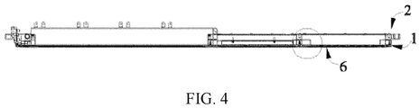
- FIG. 4 is a sectional view of FIG. 3 .
- FIG. 5 is an enlarged view of a circled part in FIG. 4 .
- FIG. 6 is a variation of FIG. 5 .
- FIG. 7 is another view corresponding to FIG. 5 , showing another internal beam of a lower frame body of the battery box according to this application.
- FIG. 8 is a variation of FIG. 7 .
- the battery box according to this application includes a heat exchange plate 1 and a lower frame body 2.
- the battery box further includes heat insulation glue 3.
- the battery box further includes a fastener 4, a heat insulation pad 5, and a protective plate 6.
- the heat exchange plate 1 is used to support battery modules 7 and exchanges heat with batteries 71 of the battery modules 7.
- the battery 71 may generally include a housing and an electrode assembly and an electrolyte that are accommodated inside the housing.
- the electrode assembly includes a positive electrode plate, a negative electrode plate, and a separator.
- the battery 71 may be a can-type (or hard-case) battery, and accordingly as shown in FIG. 1 , and the housing includes a top cover and an outer case fitted with the top cover; or the battery 71 may be a pouch-type (or soft-case) battery, and the case is made of a packaging film (such as an aluminum plastic film).
- the heat exchange plate 1 includes a first plate 14 and a second plate 15.
- the second plate 15 joins from below with the first plate 14 to form a flow passage F for a heat exchange medium to flow through, as shown in FIG. 5 and FIG. 6 .
- the first plate 14 and/or the second plate 15 may be formed by stamping.
- the heat exchange plate 1 is made of a material having high thermal conductivity, preferably a metal material, and more preferably an aluminum alloy material.
- the lower frame body 2 is located on the heat exchange plate 1.
- the lower frame body 2 includes edge beams 21 and internal beams 22.
- the edge beams 21 form a circumferential closure opened in an up-down direction Z, and the edge beams 21 and the heat exchange plate 1 together form an accommodating space with an upward opening.
- the internal beams 22 are located inside the accommodating space and divide the accommodating space into sub-accommodating spaces R for placing the battery modules 7, and a bottom plane B22 of the internal beam 22 is partly in contact with a top plane T11 of the heat exchange plate 1 in the up-down direction Z.
- the contact area between the bottom plane B22 of the internal beam 22 and the top plane T11 of the heat exchange plate 1 is reduced. This reduces the heat exchange between the heat exchange plate 1 and the bottom plane B22 of the internal beam 22, and in turn the impact on the heat exchange between the heat exchange plate 1 and the battery modules 7 (mainly the batteries 71) is reduced, and the stability, constancy and controllability of the operating temperature of the batteries 71 are improved.
- Both the edge beams 21 and the internal beams 22 can be made of a metal material, such as an aluminum alloy, and may use die castings or extrusion profiles.
- the edge beams 21 and the internal beams 22 can have cavities (that is, a later described accommodating cavity 225 is present in the internal beam 22, but no cavity is shown for the edge beam 21). In a word, they are profiles with cavities.
- the respective longitudinal directions of the edge beams 21 and the internal beams 22 may be an X direction and their respective transverse directions may be a Y direction, or the longitudinal direction may be a Y direction and the transverse direction may be an X direction.
- the transverse direction and the longitudinal direction are directions of a beam structure itself, which constitute a local coordinate system, while the X, Y, and Z directions of the battery box in FIG. 1 form a global coordinate system. There is no strict correspondence between the two coordinate systems.
- the bottom plane B22 of the internal beam 22 includes: a first plane B221, which is in contact with the top plane T11 of the heat exchange plate 1; a second plane B222, which is recessed upwardly with respect to the first plane B221 from a side of the first plane B221 in a direction that intersects with the up-down direction Z, so that the second plane B222 is spaced apart from the top plane T11 of the heat exchange plate 1 in the up-down direction Z.
- the heat insulation glue 3 is filled between the second plane B222 of the bottom plane B22 of the internal beam 22 and the top plane T11 of the heat exchange plate.
- the filling of the heat insulation glue 3 may fill seamlessly a gap between the second plane B222 of the bottom plane B22 of the internal beam 22 and the top plane T11 of the heat exchange plate 1. This prevents heat from transferring to the second plane B222 of the bottom plane B22 of the internal beam 22 through the air by means of heat radiation from the top plane T11 of the heat exchange plate 1.
- the bottom plane B22 of the internal beam 22 further includes a third plane B223, which is recessed upwardly with respect to the first plane B221 from another side of the first plane B221 opposite to the direction that intersects with the up-down direction Z, so that the third plane B223 is spaced apart from the top plane T11 of the heat exchange plate 1 in the up-down direction Z.
- the heat insulation glue 3 is filled between the third plane B223 and the top plane T11 of the heat exchange plate 1.
- the filling of the heat insulation glue 3 may fill seamlessly a gap between the third plane B223 of the bottom plane B22 of the internal beam 22 and the top plane T11 of the heat exchange plate 1. This prevents heat from transferring to the third plane B223 of the bottom plane B22 of the internal beam 22 through the air by means of heat radiation from the top plane T11 of the heat exchange plate 1.
- the top plane T11 of the heat exchange plate 1 is flat in general. This improves the flatness for heat exchange with the batteries 1 of the battery modules 7, thereby improving the uniformity of heat exchange.
- the second plane B222 and the third plane B223 may form a ring, or may not form a ring, which may be dependent on the control of heat exchange.
- the heat exchange plate 1 has a main body 12 and a bulge 13 extending from the main body 12.
- a downside of the bulge 13 is recessed upwardly with respect to the main body 12, and an upside of the bulge 13 protrudes upwardly with respect to the main body 12.
- the bulge 13 has a top surface 131 constituting part of the top plane T11 and an inclined plane 132.
- the inclined plane 132 is located laterally to the top surface 131 along the direction intersecting with the up-down direction Z.
- the bottom plane B22 of the internal beam 22 is partly in contact with the top surface 131 of the bulge 13, and the inclined plane 132 of the bulge 13 is spaced apart from the top plane T11 of the heat exchange plate 1 in the up-down direction Z.
- the contact area between the bottom plane B22 of the internal beam 22 and the top plane T11 of the heat exchange plate 1 is reduced. This reduces the heat exchange between the heat exchange plate and the bottom plane of the internal beam, and in turn the impact on the heat exchange between the heat exchange plate and the battery modules (mainly the batteries) is reduced, and the stability, constancy and controllability of the operating temperature of the batteries are improved. Moreover, the provision of the bulge 13 also helps to strengthen the performance of the internal beam 22 to buffer against outside shocks.
- the heat insulation glue 3 is filled between the bottom plane B22 of the internal beam 22 and the inclined plane 132 of the bulge 13.
- the filling of the heat insulation glue 3 may fill seamlessly a gap between the bottom plane B22 of the internal beam 22 and the inclined plane 132 of the bulge 13. This prevents heat from transferring to the bottom plane B22 of the internal beam 22 through the air by means of heat radiation from the inclined plane 132 of the bulge 13 of the heat exchange plate 1.
- the bottom plane B22 of the internal beam 22 is similar to that in FIG. 6 ; in the example in FIG. 8 , the bottom plane B22 of the internal beam 22 is flat.
- a notch 224a is provided on a lateral surface 224 of the internal beam 22 facing toward the battery.
- the provision of the notch 224a can reduce the contact area of the lateral surface of the battery module 7 with the internal beam 22 in case of impact vibration, reducing the level of unexpected heat exchange.
- the notch 224a may also reduce the weight of the internal beam 22, helping the weight reduction of the battery box.
- the internal beam 22 has an accommodating cavity 225 located above a location where the bottom plane B22 of the internal beam 22 contacts the top plane T11 of the heat exchange plate 1.
- a fastener 4 passes through the heat exchange plate 1 and the internal beam 22 at the location where the bottom plane B22 of the internal beam 22 contacts the top plane T11 of the heat exchange plate 1 and extends into the accommodating cavity 225.
- a part of the fastener 4 extending into the accommodating cavity 225 is spaced apart from a wall of the accommodating cavity 225. In this way, the part of the fastener 4 extending into the accommodating cavity 225 is prevented from coming into contact with the wall of the accommodating cavity 225, so the heat exchange area between the internal beam 22 and the heat exchange plate 1 will not increase because of the fastener 4.
- a material of the heat insulation glue 3 may be selected from any suitable materials, such as polyurethane heat insulation glue and heat insulation epoxy glue.
- the fastener 4 is used to fix the heat exchange plate 21 to the lower frame body 1.
- the fastener 4 may use any suitable forms, such as a rivet, a combination of a bolt and a nut, or a screw.
- a material of the fastener 4 is preferably a material with low thermal conductivity.
- a heat insulation pad 5 is provided under the heat exchange plate 1, as shown in FIG. 1 . With the provision of the heat insulation pad 5, heat transfer of the heat exchange plate 1 is blocked in at least the downward direction, which facilitates heat preservation for the batteries 71 of the battery module 7.
- a material of the heat insulation pad 5 may be heat insulation cotton, foam, or the like.
- a protective plate 6 supports the heat insulation pad 5 and the heat exchange plate 1 from below, as shown in FIG. 1 . Under the impact of an external force (for example, flying rocks), the protective plate 6 protects the heat exchange plate 6 from failure due to damage by the external force.
- a material of the protective plate 6 is preferably a material with strong impact resistance, such as an aluminum alloy, a stainless steel, a high-strength steel, and a hot dip galvanized dual-phase DP high-strength alloy steel.
Landscapes
- Chemical & Material Sciences (AREA)
- Chemical Kinetics & Catalysis (AREA)
- Electrochemistry (AREA)
- General Chemical & Material Sciences (AREA)
- Engineering & Computer Science (AREA)
- Manufacturing & Machinery (AREA)
- Secondary Cells (AREA)
- Battery Mounting, Suspending (AREA)
Abstract
Description
- This application relates to the battery field, and in particular, to a battery box.
- In the battery field, a battery box includes a lower frame body and a heat exchange plate. The lower framer body and the heat exchange plate form an accommodating space for accommodating a battery module. The lower housing includes a plurality of beams. The battery module includes a plurality of arranged batteries and is supported on the heat exchange plate. The heat exchange plate supports the batteries and exchanges heat with the batteries.
- A battery generally needs to stay at a constant temperature range to ensure stability and constancy of the operating temperature of the battery.
- However, because the heat exchange plate is fixed to the beams of the lower frame body, the entire bottom planes of the beams are in contact with the heat exchange plate. Therefore, there is heat transfer between the heat exchange plate and the beams of the lower frame body, which affects the heat exchange effect of the heat exchange plate on the batteries and the stability and constancy of the operating temperature of the battery.
- In view of the problem existing in the prior art, an objective of this application is to provide a battery box, which can reduce heat exchange between a heat exchange plate and bottom planes of internal beams.
- In order to achieve the above object, this application provides a battery box, which includes: a heat exchange plate; a lower frame body located on the heat exchange plate, where the lower frame body includes edge beams and internal beams, the edge beams form a circumferential closure opened in an up-down direction, the edge beams and the heat exchange plate together form an accommodating space with an upward opening, and the internal beams are located inside the accommodating space and divide the accommodating space into sub-accommodating spaces for placing battery modules; the heat exchange plate is configured to support the battery modules and exchanges heat with batteries of the battery modules, and a bottom plane of an internal beam is partly in contact with a top plane of the heat exchange plate in the up-down direction.
- In an embodiment, the bottom plane of the internal beam includes: a first plane, which is in contact with the top plane of the heat exchange plate; and a second plane, which is recessed upwardly with respect to the first plane from a side of the first plane in a direction that intersects with the up-down direction, so that the second plane is spaced apart from the top plane of the heat exchange plate in the up-down direction.
- In an embodiment, the battery box further includes heat insulation glue, the heat insulation glue being filled between the second plane of the bottom plane of the internal beam and the top plane of the heat exchange plate.
- In an embodiment, the bottom plane of the internal beam further includes a third plane, which is recessed upwardly with respect to the first plane from another side of the first plane opposite to the direction that intersects with the up-down direction, so that the third plane is spaced apart from the top plane of the heat exchange plate in the up-down direction.
- In an embodiment, the battery box further includes heat insulation glue, which is filled between the third plane and the top plane of the heat exchange plate.
- In an embodiment, the top plane of the heat exchange plate is flat in general.
- In an embodiment, the heat exchange plate has a main body and a bulge extending from the main body. A downside of the bulge is recessed upwardly with respect to the main body, and an upside of the bulge protrudes upwardly with respect to the main body. The bulge has a top surface constituting part of the top plane and an inclined plane. The inclined plane is located laterally to the top surface along the direction intersecting with the up-down direction. The bottom plane of the internal beam is partly in contact with the top surface of the bulge, and the inclined plane of the bulge is spaced apart from the top plane of the heat exchange plate in the up-down direction.
- In an embodiment, the battery box further includes heat insulation glue, which is filled between the bottom plane of the internal beam and the inclined plane of the bulge.
- In an embodiment, a notch is provided on a lateral surface of the internal beam facing toward the battery.
- In an embodiment, the internal beam has an accommodating cavity located above a location where the bottom plane of the internal beam contacts the top plane of the heat exchange plate. The battery box further includes a fastener which passes through the heat exchange plate and the internal beam at the location where the bottom plane of the internal beam contacts the top plane of the heat exchange plate and extends into the accommodating cavity. A part of the fastener extending into the accommodating cavity is spaced apart from a wall of the accommodating cavity.
- The beneficial effects of this application are as follows: by making the bottom plane of the internal beam partly in contact with the top plane of the heat exchange plate in the up-down direction, the contact area between the bottom plane of the internal beam and the top plane of the heat exchange plate is reduced. This reduces the heat exchange between the heat exchange plate and the bottom plane of the internal beam, and in turn the impact on the heat exchange between the heat exchange plate and the battery modules (mainly the batteries) is reduced, and the stability, constancy and controllability of the operating temperature of the batteries are improved.
-
-
FIG. 1 is a perspective view of a battery box according to this application, where battery modules are shown for the sake of clarity; -
FIG. 2 is a perspective view of assembly of the battery box according to this application; -
FIG. 3 is a vertical view ofFIG. 2 ; -
FIG. 4 is a sectional view ofFIG. 3 ; -
FIG. 5 is an enlarged view of a circled part inFIG. 4 ; -
FIG. 6 is a variation ofFIG. 5 ; -
FIG. 7 is another view corresponding toFIG. 5 , showing another internal beam of a lower frame body of the battery box according to this application; and -
FIG. 8 is a variation ofFIG. 7 . - Reference signs are described as follows:
X. left- right direction 22. internal beam Y. forward-back direction B22. bottom plane Z. up-down direction B221. first plane 1. heat exchange plate B222. second plane T11. top plane B223. third plane 12. main body 224. lateral surface 121. upper surface 224a. notch 13. bulge 225. accommodating cavity 131. top surface R. sub-accommodating space 132. inclined plane 3. heat insulation glue 14. first plate 4. fastener 15. second plate 5. heat insulation pad F. flow passage 6. protective plate 2. lower frame body 7. battery module 21. edge beam 71. battery - The accompanying drawings illustrate embodiments of this application and it is understood that the disclosed embodiments are merely examples of this application, which may be implemented in various forms. Therefore, specific details disclosed herein are not to be interpreted as limiting, but merely as a basis for the claims and as a representative basis for teaching one skilled in the art to implement this application in various ways.
- Additionally, expressions such as up, down, left, right, front, and back that are used to indicate directions for the operations and construction of the constituent components in the embodiments are not absolute but rather relative. Such indications are appropriate when these components are in the locations illustrated in the drawings; however, these directions should be interpreted differently when these locations change, in order to correspond to the changes.
-
FIG. 1 is a perspective view of a battery box according to this application, where battery modules are shown for the sake of clarity.FIG. 2 is an assembled perspective view of the battery box according to this application.FIG. 3 is a top view ofFIG. 2 .FIG. 4 is a sectional view ofFIG. 3 .FIG. 5 is an enlarged view of a circled part inFIG. 4 .FIG. 6 is a variation ofFIG. 5 .FIG. 7 is another view corresponding toFIG. 5 , showing another internal beam of a lower frame body of the battery box according to this application.FIG. 8 is a variation ofFIG. 7 . - The battery box according to this application includes a
heat exchange plate 1 and alower frame body 2. The battery box further includesheat insulation glue 3. The battery box further includes afastener 4, aheat insulation pad 5, and aprotective plate 6. - The
heat exchange plate 1 is used to supportbattery modules 7 and exchanges heat withbatteries 71 of thebattery modules 7. Thebattery 71 may generally include a housing and an electrode assembly and an electrolyte that are accommodated inside the housing. The electrode assembly includes a positive electrode plate, a negative electrode plate, and a separator. Thebattery 71 may be a can-type (or hard-case) battery, and accordingly as shown inFIG. 1 , and the housing includes a top cover and an outer case fitted with the top cover; or thebattery 71 may be a pouch-type (or soft-case) battery, and the case is made of a packaging film (such as an aluminum plastic film). Theheat exchange plate 1 includes afirst plate 14 and asecond plate 15. Thesecond plate 15 joins from below with thefirst plate 14 to form a flow passage F for a heat exchange medium to flow through, as shown inFIG. 5 andFIG. 6 . Thefirst plate 14 and/or thesecond plate 15 may be formed by stamping. To improve the heat exchange effect, theheat exchange plate 1 is made of a material having high thermal conductivity, preferably a metal material, and more preferably an aluminum alloy material. - The
lower frame body 2 is located on theheat exchange plate 1. Thelower frame body 2 includes edge beams 21 andinternal beams 22. The edge beams 21 form a circumferential closure opened in an up-down direction Z, and the edge beams 21 and theheat exchange plate 1 together form an accommodating space with an upward opening. Theinternal beams 22 are located inside the accommodating space and divide the accommodating space into sub-accommodating spaces R for placing thebattery modules 7, and a bottom plane B22 of theinternal beam 22 is partly in contact with a top plane T11 of theheat exchange plate 1 in the up-down direction Z. By making the bottom plane B22 of theinternal beam 22 partly in contact with the top plane T11 of theheat exchange plate 1 in the up-down direction Z, the contact area between the bottom plane B22 of theinternal beam 22 and the top plane T11 of theheat exchange plate 1 is reduced. This reduces the heat exchange between theheat exchange plate 1 and the bottom plane B22 of theinternal beam 22, and in turn the impact on the heat exchange between theheat exchange plate 1 and the battery modules 7 (mainly the batteries 71) is reduced, and the stability, constancy and controllability of the operating temperature of thebatteries 71 are improved. - Both the edge beams 21 and the
internal beams 22 can be made of a metal material, such as an aluminum alloy, and may use die castings or extrusion profiles. To reduce weight, the edge beams 21 and theinternal beams 22 can have cavities (that is, a later describedaccommodating cavity 225 is present in theinternal beam 22, but no cavity is shown for the edge beam 21). In a word, they are profiles with cavities. It is to be noted that, the respective longitudinal directions of the edge beams 21 and theinternal beams 22 may be an X direction and their respective transverse directions may be a Y direction, or the longitudinal direction may be a Y direction and the transverse direction may be an X direction. However, in this specification, the transverse direction and the longitudinal direction are directions of a beam structure itself, which constitute a local coordinate system, while the X, Y, and Z directions of the battery box inFIG. 1 form a global coordinate system. There is no strict correspondence between the two coordinate systems. - In an example in
FIG. 5 , the bottom plane B22 of theinternal beam 22 includes: a first plane B221, which is in contact with the top plane T11 of theheat exchange plate 1; a second plane B222, which is recessed upwardly with respect to the first plane B221 from a side of the first plane B221 in a direction that intersects with the up-down direction Z, so that the second plane B222 is spaced apart from the top plane T11 of theheat exchange plate 1 in the up-down direction Z. - Further, in the example in
FIG. 5 , theheat insulation glue 3 is filled between the second plane B222 of the bottom plane B22 of theinternal beam 22 and the top plane T11 of the heat exchange plate. The filling of theheat insulation glue 3 may fill seamlessly a gap between the second plane B222 of the bottom plane B22 of theinternal beam 22 and the top plane T11 of theheat exchange plate 1. This prevents heat from transferring to the second plane B222 of the bottom plane B22 of theinternal beam 22 through the air by means of heat radiation from the top plane T11 of theheat exchange plate 1. This further reduces the heat exchange between theheat exchange plate 1 and theinternal beam 22, and in turn the impact on the heat exchange between theheat exchange plate 1 and the battery modules 7 (mainly the batteries 71) is further reduced, and the stability, constancy and controllability of the operating temperature of thebatteries 71 are further improved. - In an example in
FIG. 6 , on the basis of the embodiment shown inFIG. 5 , the bottom plane B22 of theinternal beam 22 further includes a third plane B223, which is recessed upwardly with respect to the first plane B221 from another side of the first plane B221 opposite to the direction that intersects with the up-down direction Z, so that the third plane B223 is spaced apart from the top plane T11 of theheat exchange plate 1 in the up-down direction Z. By making the third plane B223 spaced apart from the top plane T11 of theheat exchange plate 1 in the up-down direction Z, the contact area between the bottom plane B22 of theinternal beam 22 and the top plane T11 of theheat exchange plate 1 is further reduced. This further reduces the heat exchange between the top plane T11 of theheat exchange plate 1 and the bottom plane B22 of theinternal beam 22, and in turn the impact on the heat exchange between theheat exchange plate 1 and the battery modules 7 (mainly the batteries 71) is further reduced, and the stability, constancy and controllability of the operating temperature of thebatteries 71 are further improved. - Further, in the example shown in
FIG. 6 , theheat insulation glue 3 is filled between the third plane B223 and the top plane T11 of theheat exchange plate 1. Again, the filling of theheat insulation glue 3 may fill seamlessly a gap between the third plane B223 of the bottom plane B22 of theinternal beam 22 and the top plane T11 of theheat exchange plate 1. This prevents heat from transferring to the third plane B223 of the bottom plane B22 of theinternal beam 22 through the air by means of heat radiation from the top plane T11 of theheat exchange plate 1. This further reduces the heat exchange between theheat exchange plate 1 and theinternal beam 22, and in turn the impact on the heat exchange between theheat exchange plate 1 and the battery modules 7 (mainly the batteries 71) is further reduced, and the stability, constancy and controllability of the operating temperature of thebatteries 71 are further improved. - In the examples in
FIG. 5 andFIG. 6 , the top plane T11 of theheat exchange plate 1 is flat in general. This improves the flatness for heat exchange with thebatteries 1 of thebattery modules 7, thereby improving the uniformity of heat exchange. The second plane B222 and the third plane B223 may form a ring, or may not form a ring, which may be dependent on the control of heat exchange. - In examples in
FIG. 7 and FIG. 8 , theheat exchange plate 1 has amain body 12 and abulge 13 extending from themain body 12. A downside of thebulge 13 is recessed upwardly with respect to themain body 12, and an upside of thebulge 13 protrudes upwardly with respect to themain body 12. Thebulge 13 has atop surface 131 constituting part of the top plane T11 and aninclined plane 132. Theinclined plane 132 is located laterally to thetop surface 131 along the direction intersecting with the up-down direction Z. The bottom plane B22 of theinternal beam 22 is partly in contact with thetop surface 131 of thebulge 13, and theinclined plane 132 of thebulge 13 is spaced apart from the top plane T11 of theheat exchange plate 1 in the up-down direction Z. By making the bottom plane B22 of theinternal beam 22 partly in contact with thetop surface 131 of thebulge 13, and theinclined plane 132 of thebulge 13 spaced apart from the top plane T11 of theheat exchange plate 1 in the up-down direction Z, the contact area between the bottom plane B22 of theinternal beam 22 and the top plane T11 of theheat exchange plate 1 is reduced. This reduces the heat exchange between the heat exchange plate and the bottom plane of the internal beam, and in turn the impact on the heat exchange between the heat exchange plate and the battery modules (mainly the batteries) is reduced, and the stability, constancy and controllability of the operating temperature of the batteries are improved. Moreover, the provision of thebulge 13 also helps to strengthen the performance of theinternal beam 22 to buffer against outside shocks. - Further, in the examples in
FIG. 7 and FIG. 8 , theheat insulation glue 3 is filled between the bottom plane B22 of theinternal beam 22 and theinclined plane 132 of thebulge 13. Again, the filling of theheat insulation glue 3 may fill seamlessly a gap between the bottom plane B22 of theinternal beam 22 and theinclined plane 132 of thebulge 13. This prevents heat from transferring to the bottom plane B22 of theinternal beam 22 through the air by means of heat radiation from theinclined plane 132 of thebulge 13 of theheat exchange plate 1. This further reduces the heat exchange between theheat exchange plate 1 and theinternal beam 22, and in turn the impact on the heat exchange between theheat exchange plate 1 and the battery modules 7 (mainly the batteries 71) is further reduced, and the stability, constancy and controllability of the operating temperature of thebatteries 71 are further improved. - In the example in
FIG. 7 , the bottom plane B22 of theinternal beam 22 is similar to that inFIG. 6 ; in the example inFIG. 8 , the bottom plane B22 of theinternal beam 22 is flat. - In the examples in
FIG. 7 and FIG. 8 , anotch 224a is provided on alateral surface 224 of theinternal beam 22 facing toward the battery. The provision of thenotch 224a can reduce the contact area of the lateral surface of thebattery module 7 with theinternal beam 22 in case of impact vibration, reducing the level of unexpected heat exchange. Moreover, thenotch 224a may also reduce the weight of theinternal beam 22, helping the weight reduction of the battery box. - In the examples in
FIG. 5 to FIG. 8 , theinternal beam 22 has anaccommodating cavity 225 located above a location where the bottom plane B22 of theinternal beam 22 contacts the top plane T11 of theheat exchange plate 1. Afastener 4 passes through theheat exchange plate 1 and theinternal beam 22 at the location where the bottom plane B22 of theinternal beam 22 contacts the top plane T11 of theheat exchange plate 1 and extends into theaccommodating cavity 225. A part of thefastener 4 extending into theaccommodating cavity 225 is spaced apart from a wall of theaccommodating cavity 225. In this way, the part of thefastener 4 extending into theaccommodating cavity 225 is prevented from coming into contact with the wall of theaccommodating cavity 225, so the heat exchange area between theinternal beam 22 and theheat exchange plate 1 will not increase because of thefastener 4. - A material of the
heat insulation glue 3 may be selected from any suitable materials, such as polyurethane heat insulation glue and heat insulation epoxy glue. - The
fastener 4 is used to fix theheat exchange plate 21 to thelower frame body 1. Thefastener 4 may use any suitable forms, such as a rivet, a combination of a bolt and a nut, or a screw. A material of thefastener 4 is preferably a material with low thermal conductivity. - A
heat insulation pad 5 is provided under theheat exchange plate 1, as shown inFIG. 1 . With the provision of theheat insulation pad 5, heat transfer of theheat exchange plate 1 is blocked in at least the downward direction, which facilitates heat preservation for thebatteries 71 of thebattery module 7. A material of theheat insulation pad 5 may be heat insulation cotton, foam, or the like. - A
protective plate 6 supports theheat insulation pad 5 and theheat exchange plate 1 from below, as shown inFIG. 1 . Under the impact of an external force (for example, flying rocks), theprotective plate 6 protects theheat exchange plate 6 from failure due to damage by the external force. A material of theprotective plate 6 is preferably a material with strong impact resistance, such as an aluminum alloy, a stainless steel, a high-strength steel, and a hot dip galvanized dual-phase DP high-strength alloy steel. - The above detailed description describes various example embodiments, but this specification is not intended to be limited to the specifically disclosed combinations. Therefore, unless otherwise stated, the various features disclosed herein can be combined together to form a plurality of additional combinations that are not shown for the sake of clarity.
Claims (10)
- A battery box, comprising:a heat exchange plate (1); anda lower frame body (2) located on the heat exchange plate (1), wherein the lower frame body (2) comprises edge beams (21) and internal beams (22), the edge beams (21) form a circumferential closure opened in an up-down direction (Z), the edge beams (21) and the heat exchange plate (1) together form an accommodating space with an upward opening, and the internal beams (22) are located inside the accommodating space and divide the accommodating space into sub-accommodating spaces (R) for placing battery modules (7); the heat exchange plate (1) is configured to support the battery modules (7) and exchanges heat with batteries (71) of the battery modules (7), and a bottom plane (B22) of the internal beam (22) is partly in contact with a top plane (T11) of the heat exchange plate (1) in the up-down direction (Z).
- The battery box according to claim 1, wherein the bottom plane (B22) of the internal beam (22) further comprises:a first plane (B221), which is in contact with the top plane (T11) of the heat exchange plate (1); anda second plane (B222), which is recessed upwardly with respect to the first plane (B221) from a side of the first plane (B221) in a direction that intersects with the up-down direction (Z), so that the second plane (B222) is spaced apart from the top plane (T11) of the heat exchange plate (1) in the up-down direction (Z).
- The battery box according to claim 2, wherein the battery box further comprises heat insulation glue (3), the heat insulation glue (3) being filled between the second plane (B222) of the bottom plane (B22) of the internal beam (22) and the top plane (T11) of the heat exchange plate (1).
- The battery box according to claim 2, wherein the bottom plane (B22) of the internal beam (22) further comprises a third plane (B223), which is recessed upwardly with respect to the first plane (B221) from another side of the first plane (B221) opposite to the direction that intersects with the up-down direction (Z), so that the third plane (B223) is spaced apart from the top plane (T11) of the heat exchange plate (1) in the up-down direction (Z).
- The battery box according to claim 4, wherein the battery box further comprises heat insulation glue (3), the heat insulation glue (3) being filled between the third plane (B223) and the top plane (T11) of the heat exchange plate (1).
- The battery box according to any one of claims 1 to 5, wherein the top plane (T11) of the heat exchange plate (1) is flat in general.
- The battery box according to any one of claims 1 to 5, wherein
the heat exchange plate (1) has a main body (12) and a bulge (13) extending from the main body (12), wherein a downside of the bulge (13) is recessed upwardly with respect to the main body (12), and an upside of the bulge (13) protrudes upwardly with respect to the main body (12), the bulge (13) has a top surface (131) constituting part of the top plane (T11) and an inclined plane (132), the inclined plane (132) is located laterally to the top surface (131) along the direction intersecting with the up-down direction (Z), the bottom plane (B22) of the internal beam (22) is partly in contact with the top surface (131) of the bulge (13), and the inclined plane (132) of the bulge (13) is spaced apart from the top plane (T11) of the heat exchange plate (1) in the up-down direction (Z). - The battery box according to claim 7, wherein the battery box further comprises heat insulation glue (3), the heat insulation glue (3) being filled between the bottom plane (B22) of the internal beam (22) and the inclined plane (132) of the bulge (13).
- The battery box according to claim 1, wherein a notch (224a) is provided on a lateral surface (224) of the internal beam (22) facing toward the battery.
- The battery box according to claim 1, wherein the internal beam (22) has an accommodating cavity (225) located above a location where the bottom plane (B22) of the internal beam (22) contacts the top plane (T11) of the heat exchange plate (1); and
the battery box further comprises a fastener (4), wherein the fastener (4) passes through the heat exchange plate (1) and the internal beam (22) at the location where the bottom plane (B22) of the internal beam (22) contacts the top plane (T11) of the heat exchange plate (1) and extends into the accommodating cavity (225), and a part of the fastener (4) extending into the accommodating cavity (225) is spaced apart from a wall of the accommodating cavity (225).
Applications Claiming Priority (2)
| Application Number | Priority Date | Filing Date | Title |
|---|---|---|---|
| CN201822266635.2U CN209183612U (en) | 2018-12-29 | 2018-12-29 | battery box |
| PCT/CN2019/126001 WO2020135156A1 (en) | 2018-12-29 | 2019-12-17 | Battery box |
Publications (3)
| Publication Number | Publication Date |
|---|---|
| EP3799151A1 true EP3799151A1 (en) | 2021-03-31 |
| EP3799151A4 EP3799151A4 (en) | 2021-10-13 |
| EP3799151B1 EP3799151B1 (en) | 2024-05-01 |
Family
ID=67378178
Family Applications (1)
| Application Number | Title | Priority Date | Filing Date |
|---|---|---|---|
| EP19903870.4A Active EP3799151B1 (en) | 2018-12-29 | 2019-12-17 | Battery box |
Country Status (5)
| Country | Link |
|---|---|
| US (2) | US12283674B2 (en) |
| EP (1) | EP3799151B1 (en) |
| CN (1) | CN209183612U (en) |
| HU (1) | HUE067143T2 (en) |
| WO (1) | WO2020135156A1 (en) |
Cited By (11)
| Publication number | Priority date | Publication date | Assignee | Title |
|---|---|---|---|---|
| EP4261967A3 (en) * | 2022-04-11 | 2024-05-15 | CALB Co., Ltd. | Battery device, assembling method and assembling equipment thereof, and battery component positioning tooling |
| US12230826B2 (en) | 2022-03-23 | 2025-02-18 | Ford Global Technologies, Llc | Methods for assembling traction battery packs |
| US12275298B2 (en) | 2022-03-23 | 2025-04-15 | Ford Global Technologies, Llc | Traction battery packs with cell-to-pack battery systems housed within irregularly shaped enclosures |
| US12374750B2 (en) | 2022-03-23 | 2025-07-29 | Ford Global Technologies, Llc | Traction battery pack assembling method |
| US12424695B2 (en) | 2022-03-23 | 2025-09-23 | Ford Global Technologies, Llc | Retention assemblies for traction battery packs with cell-to-pack battery systems |
| EP4567991A4 (en) * | 2022-12-02 | 2025-11-05 | Lg Energy Solution Ltd | BATTERY PACK |
| US12479327B2 (en) | 2022-03-23 | 2025-11-25 | Ford Global Technologies, Llc | Traction battery pack cell stack removal method and battery pack assembly |
| US12506215B2 (en) | 2022-03-23 | 2025-12-23 | Ford Global Technologies, Llc | Enclosure cover attachment configurations for traction battery packs with cell-to-pack battery systems |
| US12525637B2 (en) | 2022-03-23 | 2026-01-13 | Ford Global Technologies, Llc | Traction battery pack assembling method |
| US12567642B2 (en) | 2022-03-23 | 2026-03-03 | Ford Global Technologies, Llc | Shim systems for traction battery packs |
| US12603373B2 (en) | 2022-03-23 | 2026-04-14 | Ford Global Technologies, Llc | Traction battery pack assembling method |
Families Citing this family (5)
| Publication number | Priority date | Publication date | Assignee | Title |
|---|---|---|---|---|
| CN209183612U (en) | 2018-12-29 | 2019-07-30 | 宁德时代新能源科技股份有限公司 | battery box |
| CN110854325B (en) * | 2019-11-13 | 2022-10-25 | 北京海纳川汽车部件股份有限公司 | Battery pack of electric vehicle and electric vehicle |
| CN216488342U (en) * | 2021-10-20 | 2022-05-10 | 宁德时代新能源科技股份有限公司 | Box, battery and electrical device |
| JP2025527906A (en) * | 2022-12-02 | 2025-08-22 | エルジー エナジー ソリューション リミテッド | Battery pack |
| CN118970338B (en) * | 2024-10-14 | 2025-01-24 | 中创新航科技集团股份有限公司 | Battery box |
Family Cites Families (7)
| Publication number | Priority date | Publication date | Assignee | Title |
|---|---|---|---|---|
| JP5811168B2 (en) * | 2013-12-25 | 2015-11-11 | トヨタ自動車株式会社 | Battery mounting structure for vehicles |
| CN204230382U (en) * | 2014-10-31 | 2015-03-25 | 比亚迪股份有限公司 | A kind of heating panel and electrokinetic cell system |
| KR102376981B1 (en) * | 2015-04-22 | 2022-03-21 | 삼성전자주식회사 | Electronic device having heat transffering structure |
| CN207116549U (en) * | 2017-08-31 | 2018-03-16 | 宁德时代新能源科技股份有限公司 | Framework and battery modules |
| CN207818674U (en) * | 2017-12-27 | 2018-09-04 | 宁德时代新能源科技股份有限公司 | battery pack |
| CN108365156B (en) * | 2018-04-24 | 2024-06-18 | 北京新能源汽车股份有限公司 | Battery Pack and Vehicle |
| CN209183612U (en) * | 2018-12-29 | 2019-07-30 | 宁德时代新能源科技股份有限公司 | battery box |
-
2018
- 2018-12-29 CN CN201822266635.2U patent/CN209183612U/en active Active
-
2019
- 2019-12-17 EP EP19903870.4A patent/EP3799151B1/en active Active
- 2019-12-17 HU HUE19903870A patent/HUE067143T2/en unknown
- 2019-12-17 WO PCT/CN2019/126001 patent/WO2020135156A1/en not_active Ceased
-
2020
- 2020-12-30 US US17/138,597 patent/US12283674B2/en active Active
-
2025
- 2025-03-14 US US19/080,177 patent/US20250210751A1/en active Pending
Cited By (11)
| Publication number | Priority date | Publication date | Assignee | Title |
|---|---|---|---|---|
| US12230826B2 (en) | 2022-03-23 | 2025-02-18 | Ford Global Technologies, Llc | Methods for assembling traction battery packs |
| US12275298B2 (en) | 2022-03-23 | 2025-04-15 | Ford Global Technologies, Llc | Traction battery packs with cell-to-pack battery systems housed within irregularly shaped enclosures |
| US12374750B2 (en) | 2022-03-23 | 2025-07-29 | Ford Global Technologies, Llc | Traction battery pack assembling method |
| US12424695B2 (en) | 2022-03-23 | 2025-09-23 | Ford Global Technologies, Llc | Retention assemblies for traction battery packs with cell-to-pack battery systems |
| US12479327B2 (en) | 2022-03-23 | 2025-11-25 | Ford Global Technologies, Llc | Traction battery pack cell stack removal method and battery pack assembly |
| US12506215B2 (en) | 2022-03-23 | 2025-12-23 | Ford Global Technologies, Llc | Enclosure cover attachment configurations for traction battery packs with cell-to-pack battery systems |
| US12525637B2 (en) | 2022-03-23 | 2026-01-13 | Ford Global Technologies, Llc | Traction battery pack assembling method |
| US12567642B2 (en) | 2022-03-23 | 2026-03-03 | Ford Global Technologies, Llc | Shim systems for traction battery packs |
| US12603373B2 (en) | 2022-03-23 | 2026-04-14 | Ford Global Technologies, Llc | Traction battery pack assembling method |
| EP4261967A3 (en) * | 2022-04-11 | 2024-05-15 | CALB Co., Ltd. | Battery device, assembling method and assembling equipment thereof, and battery component positioning tooling |
| EP4567991A4 (en) * | 2022-12-02 | 2025-11-05 | Lg Energy Solution Ltd | BATTERY PACK |
Also Published As
| Publication number | Publication date |
|---|---|
| US12283674B2 (en) | 2025-04-22 |
| HUE067143T2 (en) | 2024-10-28 |
| EP3799151A4 (en) | 2021-10-13 |
| US20250210751A1 (en) | 2025-06-26 |
| EP3799151B1 (en) | 2024-05-01 |
| CN209183612U (en) | 2019-07-30 |
| WO2020135156A1 (en) | 2020-07-02 |
| US20210119279A1 (en) | 2021-04-22 |
Similar Documents
| Publication | Publication Date | Title |
|---|---|---|
| US12283674B2 (en) | Battery box | |
| EP4148874B1 (en) | Battery box | |
| US10720680B2 (en) | Tray assembly for automobile use, battery pack body for automobile use and automobile | |
| EP3920261B1 (en) | Battery module having module housing of thin-plate type and battery pack including the same | |
| EP3795399B1 (en) | Battery tray and vehicle | |
| JP7114799B2 (en) | Battery packs, vehicles and energy storage devices | |
| US20200212397A1 (en) | Battery box | |
| US12087930B2 (en) | Battery pack | |
| CN205488289U (en) | Battery box and battery packing that has it are put and electric vehicle | |
| WO2020135154A1 (en) | Battery pack and frame for battery pack | |
| KR102611509B1 (en) | Battery carrying tray provided with protecting structure | |
| KR20240101667A (en) | Edge beams for battery trays, battery trays, battery packs, and vehicles | |
| KR102035578B1 (en) | Cargo hold structure for container ship | |
| KR20260046469A (en) | Heat exchange structures, battery packs, and electrical devices | |
| US20240014493A1 (en) | Battery pack and device including the same | |
| CN213752878U (en) | Battery pack assemblies and vehicles for vehicles | |
| CN116742238A (en) | Battery cabinet and energy storage device | |
| CN202157360U (en) | Radiator structure of excavating/loading machine | |
| CN223884529U (en) | Battery box and battery pack | |
| US20250210769A1 (en) | Container module | |
| CN224053205U (en) | A type of air-cooled lower housing | |
| CN217691442U (en) | Battery box, battery package and vehicle | |
| CN110581243A (en) | Battery module support device and vehicle | |
| KR102821854B1 (en) | Battery Pack, Vehicle, and Energy Storage System | |
| JP2005193697A (en) | Body structure with power supply module |
Legal Events
| Date | Code | Title | Description |
|---|---|---|---|
| STAA | Information on the status of an ep patent application or granted ep patent |
Free format text: STATUS: THE INTERNATIONAL PUBLICATION HAS BEEN MADE |
|
| PUAI | Public reference made under article 153(3) epc to a published international application that has entered the european phase |
Free format text: ORIGINAL CODE: 0009012 |
|
| STAA | Information on the status of an ep patent application or granted ep patent |
Free format text: STATUS: REQUEST FOR EXAMINATION WAS MADE |
|
| 17P | Request for examination filed |
Effective date: 20201221 |
|
| AK | Designated contracting states |
Kind code of ref document: A1 Designated state(s): AL AT BE BG CH CY CZ DE DK EE ES FI FR GB GR HR HU IE IS IT LI LT LU LV MC MK MT NL NO PL PT RO RS SE SI SK SM TR |
|
| AX | Request for extension of the european patent |
Extension state: BA ME |
|
| REG | Reference to a national code |
Ref country code: DE Ref legal event code: R079 Free format text: PREVIOUS MAIN CLASS: H01M0002100000 Ipc: H01M0010613000 Ref country code: DE Ref legal event code: R079 Ref document number: 602019051714 Country of ref document: DE Free format text: PREVIOUS MAIN CLASS: H01M0002100000 Ipc: H01M0010613000 |
|
| A4 | Supplementary search report drawn up and despatched |
Effective date: 20210910 |
|
| RIC1 | Information provided on ipc code assigned before grant |
Ipc: H01M 10/6554 20140101ALI20210906BHEP Ipc: H01M 10/653 20140101ALI20210906BHEP Ipc: H01M 50/209 20210101ALI20210906BHEP Ipc: H01M 10/655 20140101ALI20210906BHEP Ipc: H01M 10/613 20140101AFI20210906BHEP |
|
| DAV | Request for validation of the european patent (deleted) | ||
| DAX | Request for extension of the european patent (deleted) | ||
| STAA | Information on the status of an ep patent application or granted ep patent |
Free format text: STATUS: EXAMINATION IS IN PROGRESS |
|
| 17Q | First examination report despatched |
Effective date: 20230113 |
|
| GRAP | Despatch of communication of intention to grant a patent |
Free format text: ORIGINAL CODE: EPIDOSNIGR1 |
|
| STAA | Information on the status of an ep patent application or granted ep patent |
Free format text: STATUS: GRANT OF PATENT IS INTENDED |
|
| INTG | Intention to grant announced |
Effective date: 20240214 |
|
| GRAS | Grant fee paid |
Free format text: ORIGINAL CODE: EPIDOSNIGR3 |
|
| GRAA | (expected) grant |
Free format text: ORIGINAL CODE: 0009210 |
|
| STAA | Information on the status of an ep patent application or granted ep patent |
Free format text: STATUS: THE PATENT HAS BEEN GRANTED |
|
| AK | Designated contracting states |
Kind code of ref document: B1 Designated state(s): AL AT BE BG CH CY CZ DE DK EE ES FI FR GB GR HR HU IE IS IT LI LT LU LV MC MK MT NL NO PL PT RO RS SE SI SK SM TR |
|
| REG | Reference to a national code |
Ref country code: GB Ref legal event code: FG4D |
|
| REG | Reference to a national code |
Ref country code: CH Ref legal event code: EP |
|
| REG | Reference to a national code |
Ref country code: DE Ref legal event code: R096 Ref document number: 602019051714 Country of ref document: DE |
|
| REG | Reference to a national code |
Ref country code: IE Ref legal event code: FG4D |
|
| REG | Reference to a national code |
Ref country code: DE Ref legal event code: R081 Ref document number: 602019051714 Country of ref document: DE Owner name: CONTEMPORARY AMPEREX TECHNOLOGY (HONG KONG) LI, HK Free format text: FORMER OWNER: CONTEMPORARY AMPEREX TECHNOLOGY CO., LIMITED, NINGDE CITY, FUJIAN, CN |
|
| REG | Reference to a national code |
Ref country code: LT Ref legal event code: MG9D |
|
| REG | Reference to a national code |
Ref country code: NL Ref legal event code: MP Effective date: 20240501 Ref country code: GB Ref legal event code: 732E Free format text: REGISTERED BETWEEN 20240808 AND 20240814 |
|
| REG | Reference to a national code |
Ref country code: HU Ref legal event code: GB9C Owner name: CONTEMPORARY AMPEREX TECHNOLOGY (HONG KONG) LIMITED, HK Free format text: FORMER OWNER(S): CONTEMPORARY AMPEREX TECHNOLOGY CO., LIMITED, CN Ref country code: HU Ref legal event code: FH1C Free format text: FORMER REPRESENTATIVE(S): DANUBIA SZABADALMI ES JOGI IRODA KFT., HU Representative=s name: DANUBIA SZABADALMI ES JOGI IRODA KFT., HU |
|
| RAP2 | Party data changed (patent owner data changed or rights of a patent transferred) |
Owner name: CONTEMPORARY AMPEREX TECHNOLOGY(HONG KONG) LIMITED |
|
| PG25 | Lapsed in a contracting state [announced via postgrant information from national office to epo] |
Ref country code: IS Free format text: LAPSE BECAUSE OF FAILURE TO SUBMIT A TRANSLATION OF THE DESCRIPTION OR TO PAY THE FEE WITHIN THE PRESCRIBED TIME-LIMIT Effective date: 20240901 |
|
| PG25 | Lapsed in a contracting state [announced via postgrant information from national office to epo] |
Ref country code: BG Free format text: LAPSE BECAUSE OF FAILURE TO SUBMIT A TRANSLATION OF THE DESCRIPTION OR TO PAY THE FEE WITHIN THE PRESCRIBED TIME-LIMIT Effective date: 20240501 |
|
| PG25 | Lapsed in a contracting state [announced via postgrant information from national office to epo] |
Ref country code: HR Free format text: LAPSE BECAUSE OF FAILURE TO SUBMIT A TRANSLATION OF THE DESCRIPTION OR TO PAY THE FEE WITHIN THE PRESCRIBED TIME-LIMIT Effective date: 20240501 Ref country code: FI Free format text: LAPSE BECAUSE OF FAILURE TO SUBMIT A TRANSLATION OF THE DESCRIPTION OR TO PAY THE FEE WITHIN THE PRESCRIBED TIME-LIMIT Effective date: 20240501 |
|
| PG25 | Lapsed in a contracting state [announced via postgrant information from national office to epo] |
Ref country code: GR Free format text: LAPSE BECAUSE OF FAILURE TO SUBMIT A TRANSLATION OF THE DESCRIPTION OR TO PAY THE FEE WITHIN THE PRESCRIBED TIME-LIMIT Effective date: 20240802 |
|
| PG25 | Lapsed in a contracting state [announced via postgrant information from national office to epo] |
Ref country code: PT Free format text: LAPSE BECAUSE OF FAILURE TO SUBMIT A TRANSLATION OF THE DESCRIPTION OR TO PAY THE FEE WITHIN THE PRESCRIBED TIME-LIMIT Effective date: 20240902 |
|
| REG | Reference to a national code |
Ref country code: AT Ref legal event code: MK05 Ref document number: 1683664 Country of ref document: AT Kind code of ref document: T Effective date: 20240501 |
|
| PG25 | Lapsed in a contracting state [announced via postgrant information from national office to epo] |
Ref country code: NL Free format text: LAPSE BECAUSE OF FAILURE TO SUBMIT A TRANSLATION OF THE DESCRIPTION OR TO PAY THE FEE WITHIN THE PRESCRIBED TIME-LIMIT Effective date: 20240501 |
|
| PG25 | Lapsed in a contracting state [announced via postgrant information from national office to epo] |
Ref country code: ES Free format text: LAPSE BECAUSE OF FAILURE TO SUBMIT A TRANSLATION OF THE DESCRIPTION OR TO PAY THE FEE WITHIN THE PRESCRIBED TIME-LIMIT Effective date: 20240501 |
|
| PG25 | Lapsed in a contracting state [announced via postgrant information from national office to epo] |
Ref country code: AT Free format text: LAPSE BECAUSE OF FAILURE TO SUBMIT A TRANSLATION OF THE DESCRIPTION OR TO PAY THE FEE WITHIN THE PRESCRIBED TIME-LIMIT Effective date: 20240501 |
|
| PG25 | Lapsed in a contracting state [announced via postgrant information from national office to epo] |
Ref country code: PL Free format text: LAPSE BECAUSE OF FAILURE TO SUBMIT A TRANSLATION OF THE DESCRIPTION OR TO PAY THE FEE WITHIN THE PRESCRIBED TIME-LIMIT Effective date: 20240501 |
|
| REG | Reference to a national code |
Ref country code: HU Ref legal event code: AG4A Ref document number: E067143 Country of ref document: HU |
|
| PG25 | Lapsed in a contracting state [announced via postgrant information from national office to epo] |
Ref country code: LV Free format text: LAPSE BECAUSE OF FAILURE TO SUBMIT A TRANSLATION OF THE DESCRIPTION OR TO PAY THE FEE WITHIN THE PRESCRIBED TIME-LIMIT Effective date: 20240501 |
|
| PG25 | Lapsed in a contracting state [announced via postgrant information from national office to epo] |
Ref country code: PT Free format text: LAPSE BECAUSE OF FAILURE TO SUBMIT A TRANSLATION OF THE DESCRIPTION OR TO PAY THE FEE WITHIN THE PRESCRIBED TIME-LIMIT Effective date: 20240902 Ref country code: PL Free format text: LAPSE BECAUSE OF FAILURE TO SUBMIT A TRANSLATION OF THE DESCRIPTION OR TO PAY THE FEE WITHIN THE PRESCRIBED TIME-LIMIT Effective date: 20240501 Ref country code: NO Free format text: LAPSE BECAUSE OF FAILURE TO SUBMIT A TRANSLATION OF THE DESCRIPTION OR TO PAY THE FEE WITHIN THE PRESCRIBED TIME-LIMIT Effective date: 20240801 Ref country code: NL Free format text: LAPSE BECAUSE OF FAILURE TO SUBMIT A TRANSLATION OF THE DESCRIPTION OR TO PAY THE FEE WITHIN THE PRESCRIBED TIME-LIMIT Effective date: 20240501 Ref country code: LV Free format text: LAPSE BECAUSE OF FAILURE TO SUBMIT A TRANSLATION OF THE DESCRIPTION OR TO PAY THE FEE WITHIN THE PRESCRIBED TIME-LIMIT Effective date: 20240501 Ref country code: IS Free format text: LAPSE BECAUSE OF FAILURE TO SUBMIT A TRANSLATION OF THE DESCRIPTION OR TO PAY THE FEE WITHIN THE PRESCRIBED TIME-LIMIT Effective date: 20240901 Ref country code: HR Free format text: LAPSE BECAUSE OF FAILURE TO SUBMIT A TRANSLATION OF THE DESCRIPTION OR TO PAY THE FEE WITHIN THE PRESCRIBED TIME-LIMIT Effective date: 20240501 Ref country code: GR Free format text: LAPSE BECAUSE OF FAILURE TO SUBMIT A TRANSLATION OF THE DESCRIPTION OR TO PAY THE FEE WITHIN THE PRESCRIBED TIME-LIMIT Effective date: 20240802 Ref country code: FI Free format text: LAPSE BECAUSE OF FAILURE TO SUBMIT A TRANSLATION OF THE DESCRIPTION OR TO PAY THE FEE WITHIN THE PRESCRIBED TIME-LIMIT Effective date: 20240501 Ref country code: ES Free format text: LAPSE BECAUSE OF FAILURE TO SUBMIT A TRANSLATION OF THE DESCRIPTION OR TO PAY THE FEE WITHIN THE PRESCRIBED TIME-LIMIT Effective date: 20240501 Ref country code: BG Free format text: LAPSE BECAUSE OF FAILURE TO SUBMIT A TRANSLATION OF THE DESCRIPTION OR TO PAY THE FEE WITHIN THE PRESCRIBED TIME-LIMIT Effective date: 20240501 Ref country code: AT Free format text: LAPSE BECAUSE OF FAILURE TO SUBMIT A TRANSLATION OF THE DESCRIPTION OR TO PAY THE FEE WITHIN THE PRESCRIBED TIME-LIMIT Effective date: 20240501 Ref country code: RS Free format text: LAPSE BECAUSE OF FAILURE TO SUBMIT A TRANSLATION OF THE DESCRIPTION OR TO PAY THE FEE WITHIN THE PRESCRIBED TIME-LIMIT Effective date: 20240801 |
|
| PG25 | Lapsed in a contracting state [announced via postgrant information from national office to epo] |
Ref country code: DK Free format text: LAPSE BECAUSE OF FAILURE TO SUBMIT A TRANSLATION OF THE DESCRIPTION OR TO PAY THE FEE WITHIN THE PRESCRIBED TIME-LIMIT Effective date: 20240501 |
|
| PG25 | Lapsed in a contracting state [announced via postgrant information from national office to epo] |
Ref country code: EE Free format text: LAPSE BECAUSE OF FAILURE TO SUBMIT A TRANSLATION OF THE DESCRIPTION OR TO PAY THE FEE WITHIN THE PRESCRIBED TIME-LIMIT Effective date: 20240501 |
|
| PG25 | Lapsed in a contracting state [announced via postgrant information from national office to epo] |
Ref country code: CZ Free format text: LAPSE BECAUSE OF FAILURE TO SUBMIT A TRANSLATION OF THE DESCRIPTION OR TO PAY THE FEE WITHIN THE PRESCRIBED TIME-LIMIT Effective date: 20240501 |
|
| PG25 | Lapsed in a contracting state [announced via postgrant information from national office to epo] |
Ref country code: RO Free format text: LAPSE BECAUSE OF FAILURE TO SUBMIT A TRANSLATION OF THE DESCRIPTION OR TO PAY THE FEE WITHIN THE PRESCRIBED TIME-LIMIT Effective date: 20240501 Ref country code: SK Free format text: LAPSE BECAUSE OF FAILURE TO SUBMIT A TRANSLATION OF THE DESCRIPTION OR TO PAY THE FEE WITHIN THE PRESCRIBED TIME-LIMIT Effective date: 20240501 |
|
| PG25 | Lapsed in a contracting state [announced via postgrant information from national office to epo] |
Ref country code: SM Free format text: LAPSE BECAUSE OF FAILURE TO SUBMIT A TRANSLATION OF THE DESCRIPTION OR TO PAY THE FEE WITHIN THE PRESCRIBED TIME-LIMIT Effective date: 20240501 |
|
| PG25 | Lapsed in a contracting state [announced via postgrant information from national office to epo] |
Ref country code: SM Free format text: LAPSE BECAUSE OF FAILURE TO SUBMIT A TRANSLATION OF THE DESCRIPTION OR TO PAY THE FEE WITHIN THE PRESCRIBED TIME-LIMIT Effective date: 20240501 Ref country code: SK Free format text: LAPSE BECAUSE OF FAILURE TO SUBMIT A TRANSLATION OF THE DESCRIPTION OR TO PAY THE FEE WITHIN THE PRESCRIBED TIME-LIMIT Effective date: 20240501 Ref country code: RO Free format text: LAPSE BECAUSE OF FAILURE TO SUBMIT A TRANSLATION OF THE DESCRIPTION OR TO PAY THE FEE WITHIN THE PRESCRIBED TIME-LIMIT Effective date: 20240501 Ref country code: EE Free format text: LAPSE BECAUSE OF FAILURE TO SUBMIT A TRANSLATION OF THE DESCRIPTION OR TO PAY THE FEE WITHIN THE PRESCRIBED TIME-LIMIT Effective date: 20240501 Ref country code: DK Free format text: LAPSE BECAUSE OF FAILURE TO SUBMIT A TRANSLATION OF THE DESCRIPTION OR TO PAY THE FEE WITHIN THE PRESCRIBED TIME-LIMIT Effective date: 20240501 Ref country code: CZ Free format text: LAPSE BECAUSE OF FAILURE TO SUBMIT A TRANSLATION OF THE DESCRIPTION OR TO PAY THE FEE WITHIN THE PRESCRIBED TIME-LIMIT Effective date: 20240501 |
|
| REG | Reference to a national code |
Ref country code: DE Ref legal event code: R097 Ref document number: 602019051714 Country of ref document: DE |
|
| PG25 | Lapsed in a contracting state [announced via postgrant information from national office to epo] |
Ref country code: IT Free format text: LAPSE BECAUSE OF FAILURE TO SUBMIT A TRANSLATION OF THE DESCRIPTION OR TO PAY THE FEE WITHIN THE PRESCRIBED TIME-LIMIT Effective date: 20240501 |
|
| PLBE | No opposition filed within time limit |
Free format text: ORIGINAL CODE: 0009261 |
|
| STAA | Information on the status of an ep patent application or granted ep patent |
Free format text: STATUS: NO OPPOSITION FILED WITHIN TIME LIMIT |
|
| 26N | No opposition filed |
Effective date: 20250204 |
|
| PG25 | Lapsed in a contracting state [announced via postgrant information from national office to epo] |
Ref country code: SI Free format text: LAPSE BECAUSE OF FAILURE TO SUBMIT A TRANSLATION OF THE DESCRIPTION OR TO PAY THE FEE WITHIN THE PRESCRIBED TIME-LIMIT Effective date: 20240501 |
|
| PG25 | Lapsed in a contracting state [announced via postgrant information from national office to epo] |
Ref country code: MC Free format text: LAPSE BECAUSE OF FAILURE TO SUBMIT A TRANSLATION OF THE DESCRIPTION OR TO PAY THE FEE WITHIN THE PRESCRIBED TIME-LIMIT Effective date: 20240501 |
|
| REG | Reference to a national code |
Ref country code: CH Ref legal event code: PL |
|
| PG25 | Lapsed in a contracting state [announced via postgrant information from national office to epo] |
Ref country code: LU Free format text: LAPSE BECAUSE OF NON-PAYMENT OF DUE FEES Effective date: 20241217 |
|
| PG25 | Lapsed in a contracting state [announced via postgrant information from national office to epo] |
Ref country code: SE Free format text: LAPSE BECAUSE OF FAILURE TO SUBMIT A TRANSLATION OF THE DESCRIPTION OR TO PAY THE FEE WITHIN THE PRESCRIBED TIME-LIMIT Effective date: 20240501 |
|
| REG | Reference to a national code |
Ref country code: BE Ref legal event code: MM Effective date: 20241231 |
|
| PG25 | Lapsed in a contracting state [announced via postgrant information from national office to epo] |
Ref country code: BE Free format text: LAPSE BECAUSE OF NON-PAYMENT OF DUE FEES Effective date: 20241231 |
|
| PG25 | Lapsed in a contracting state [announced via postgrant information from national office to epo] |
Ref country code: CH Free format text: LAPSE BECAUSE OF NON-PAYMENT OF DUE FEES Effective date: 20241231 |
|
| PG25 | Lapsed in a contracting state [announced via postgrant information from national office to epo] |
Ref country code: IE Free format text: LAPSE BECAUSE OF NON-PAYMENT OF DUE FEES Effective date: 20241217 |
|
| PGFP | Annual fee paid to national office [announced via postgrant information from national office to epo] |
Ref country code: DE Payment date: 20251212 Year of fee payment: 7 |
|
| PGFP | Annual fee paid to national office [announced via postgrant information from national office to epo] |
Ref country code: GB Payment date: 20251211 Year of fee payment: 7 |
|
| PGFP | Annual fee paid to national office [announced via postgrant information from national office to epo] |
Ref country code: HU Payment date: 20251209 Year of fee payment: 7 Ref country code: FR Payment date: 20251212 Year of fee payment: 7 |