EP3799150A1 - Battery box - Google Patents
Battery box Download PDFInfo
- Publication number
- EP3799150A1 EP3799150A1 EP19903399.4A EP19903399A EP3799150A1 EP 3799150 A1 EP3799150 A1 EP 3799150A1 EP 19903399 A EP19903399 A EP 19903399A EP 3799150 A1 EP3799150 A1 EP 3799150A1
- Authority
- EP
- European Patent Office
- Prior art keywords
- battery
- row
- box
- path
- along
- Prior art date
- Legal status (The legal status is an assumption and is not a legal conclusion. Google has not performed a legal analysis and makes no representation as to the accuracy of the status listed.)
- Granted
Links
Images





Classifications
-
- H—ELECTRICITY
- H01—ELECTRIC ELEMENTS
- H01M—PROCESSES OR MEANS, e.g. BATTERIES, FOR THE DIRECT CONVERSION OF CHEMICAL ENERGY INTO ELECTRICAL ENERGY
- H01M50/00—Constructional details or processes of manufacture of the non-active parts of electrochemical cells other than fuel cells, e.g. hybrid cells
- H01M50/30—Arrangements for facilitating escape of gases
- H01M50/342—Non-re-sealable arrangements
- H01M50/3425—Non-re-sealable arrangements in the form of rupturable membranes or weakened parts, e.g. pierced with the aid of a sharp member
-
- H—ELECTRICITY
- H01—ELECTRIC ELEMENTS
- H01M—PROCESSES OR MEANS, e.g. BATTERIES, FOR THE DIRECT CONVERSION OF CHEMICAL ENERGY INTO ELECTRICAL ENERGY
- H01M50/00—Constructional details or processes of manufacture of the non-active parts of electrochemical cells other than fuel cells, e.g. hybrid cells
- H01M50/10—Primary casings; Jackets or wrappings
- H01M50/183—Sealing members
- H01M50/19—Sealing members characterised by the material
- H01M50/198—Sealing members characterised by the material characterised by physical properties, e.g. adhesiveness or hardness
-
- H—ELECTRICITY
- H01—ELECTRIC ELEMENTS
- H01M—PROCESSES OR MEANS, e.g. BATTERIES, FOR THE DIRECT CONVERSION OF CHEMICAL ENERGY INTO ELECTRICAL ENERGY
- H01M50/00—Constructional details or processes of manufacture of the non-active parts of electrochemical cells other than fuel cells, e.g. hybrid cells
- H01M50/30—Arrangements for facilitating escape of gases
- H01M50/317—Re-sealable arrangements
-
- H—ELECTRICITY
- H01—ELECTRIC ELEMENTS
- H01M—PROCESSES OR MEANS, e.g. BATTERIES, FOR THE DIRECT CONVERSION OF CHEMICAL ENERGY INTO ELECTRICAL ENERGY
- H01M50/00—Constructional details or processes of manufacture of the non-active parts of electrochemical cells other than fuel cells, e.g. hybrid cells
- H01M50/30—Arrangements for facilitating escape of gases
- H01M50/35—Gas exhaust passages comprising elongated, tortuous or labyrinth-shaped exhaust passages
- H01M50/367—Internal gas exhaust passages forming part of the battery cover or case; Double cover vent systems
-
- H—ELECTRICITY
- H01—ELECTRIC ELEMENTS
- H01M—PROCESSES OR MEANS, e.g. BATTERIES, FOR THE DIRECT CONVERSION OF CHEMICAL ENERGY INTO ELECTRICAL ENERGY
- H01M50/00—Constructional details or processes of manufacture of the non-active parts of electrochemical cells other than fuel cells, e.g. hybrid cells
- H01M50/30—Arrangements for facilitating escape of gases
- H01M50/383—Flame arresting or ignition-preventing means
-
- H—ELECTRICITY
- H01—ELECTRIC ELEMENTS
- H01M—PROCESSES OR MEANS, e.g. BATTERIES, FOR THE DIRECT CONVERSION OF CHEMICAL ENERGY INTO ELECTRICAL ENERGY
- H01M2220/00—Batteries for particular applications
- H01M2220/20—Batteries in motive systems, e.g. vehicle, ship, plane
-
- H—ELECTRICITY
- H01—ELECTRIC ELEMENTS
- H01M—PROCESSES OR MEANS, e.g. BATTERIES, FOR THE DIRECT CONVERSION OF CHEMICAL ENERGY INTO ELECTRICAL ENERGY
- H01M50/00—Constructional details or processes of manufacture of the non-active parts of electrochemical cells other than fuel cells, e.g. hybrid cells
- H01M50/20—Mountings; Secondary casings or frames; Racks, modules or packs; Suspension devices; Shock absorbers; Transport or carrying devices; Holders
- H01M50/204—Racks, modules or packs for multiple batteries or multiple cells
- H01M50/207—Racks, modules or packs for multiple batteries or multiple cells characterised by their shape
- H01M50/209—Racks, modules or packs for multiple batteries or multiple cells characterised by their shape adapted for prismatic or rectangular cells
-
- Y—GENERAL TAGGING OF NEW TECHNOLOGICAL DEVELOPMENTS; GENERAL TAGGING OF CROSS-SECTIONAL TECHNOLOGIES SPANNING OVER SEVERAL SECTIONS OF THE IPC; TECHNICAL SUBJECTS COVERED BY FORMER USPC CROSS-REFERENCE ART COLLECTIONS [XRACs] AND DIGESTS
- Y02—TECHNOLOGIES OR APPLICATIONS FOR MITIGATION OR ADAPTATION AGAINST CLIMATE CHANGE
- Y02E—REDUCTION OF GREENHOUSE GAS [GHG] EMISSIONS, RELATED TO ENERGY GENERATION, TRANSMISSION OR DISTRIBUTION
- Y02E60/00—Enabling technologies; Technologies with a potential or indirect contribution to GHG emissions mitigation
- Y02E60/10—Energy storage using batteries
Definitions
- This application relates to the field of batteries, and in particular, to a battery box.
- an objective of this application is to provide a battery box and a vehicle, which can export gas production and heat inside a battery to the outside when the battery fails, preventing heat from spreading and improving safety of a battery pack.
- this application provides a battery box, which includes: a box body including a closed accommodation space; and a first battery group accommodated in the accommodation space.
- the first battery group includes a first battery row, where the first battery row includes a plurality of batteries arranged side by side along a width direction, an explosion-proof valve is disposed on the top of each battery, and all explosion-proof valves of the first battery row form a first explosion-proof valve row; a first guide plate, configured to extend along the width direction and be sealed and disposed above the first explosion-proof valve row, where the first guide plate and an upper surface of the first battery row form a first path extended along the width direction; and a first end plate, disposed on one side in the width direction of the first battery row and provided with a first recess, where the first recess is located below the first guide plate in a height direction and communicates with one end of the first path, and an opening is disposed at a position, corresponding to the first recess, of the box body.
- the battery box includes:
- the first battery group further includes: a second end plate, disposed on the other side in the width direction of the first battery row and provided with a second recess, where the second recess is located below the first guide plate in the height direction and communicates with the other end of the first path, and an opening is disposed at a position, corresponding to the second recess, of the box body.
- the first battery group has more than two first battery rows arranged side by side along a length direction; a quantity of the first guide plates is more than two, and each of the first guide plates is sealed and disposed above a corresponding first explosion-proof valve row and forms a first path with an upper surface of a corresponding first battery row; the first end plate has more than two first recesses, and each of the first recesses communicates with one end of a corresponding first path; and the second end plate has more than two second recesses, and each of the second recesses communicates with the other end of a corresponding first path.
- the battery box further includes: a second battery group, where the second battery group and the first battery group arranged side by side along the width direction.
- the second battery group includes: a second battery row, where the second battery row includes a plurality of batteries arranged side by side along the width direction, an explosion-proof valve is disposed on the top of each battery, and all explosion-proof valves of the second battery row form a second explosion-proof valve row; a second guide plate, configured to extend along the width direction and be sealed and disposed above the second explosion-proof valve row, where the second guide plate and an upper surface of the second battery row form a second path extended along the width direction; and a third end plate, disposed on one side in the width direction of the second battery row and provided with a third recess, where the third recess is located below the second guide plate in the height direction and communicates with one end of the second path, and an opening is disposed at a position, corresponding to the third recess, of the box body.
- a quantity of the first battery groups arranged in the length direction is more than two, and a quantity of the second battery groups arranged in the length direction is more than two.
- the battery box further includes: a first beam, disposed between two adjacent first battery groups and two adjacent second battery groups; and a second beam, sandwiched between the first battery group and the second battery group along the width direction, where the first beam and the second beam divide the accommodation space into a plurality of subspaces, and each of the first battery groups and each of the second battery groups are respectively accommodated in corresponding subspaces.
- the first guide plate includes: a main body; side portions, connected to both sides of the main body along the length direction and extending along the first battery row; and fixing portions, connected to the side portions and extending outward along the length direction, where the fixing portions are sealed and fixed on an upper surface of the first battery row.
- the first guide plate further includes: a stop portion, disposed at one end of the main body along the width direction and connected to the ends of the main body, the side portions and the fixed portions.
- an adsorption material is provided in the first path formed by the first guide plate and the upper surface of the first battery row.
- the box body includes: a lower box body; and an upper box body, configured to be sealed and installed on the lower box body along the height direction and enclose the accommodation space with the lower box body.
- the lower box includes: a bottom wall; a first peripheral wall, connected to the periphery of the bottom wall and extending in the direction of the upper box; and a first flange, connected to the first peripheral wall and extending outward along an upper edge of the first peripheral wall.
- the upper box includes: a top wall; a second peripheral wall, connected to the periphery of the top wall and extending in the direction of the lower box; and a second flange, connected to the second peripheral wall and extending outward along the lower edge of the second peripheral wall.
- the upper box is installed on the lower box along the height direction, and the second flange of the upper box is sealingly connected with the first flange of the lower box.
- a portion of the second flange of the upper box bulges upward in the height direction to form a corresponding opening with the first flange of the lower box.
- the beneficial effects of this application are as follows: In the battery box according to this application, the first path, the first recess, and the opening are disposed to provide a discharge passage for gas production and heat in a battery when the battery fails, so that internal gas production and heat are exported to the outside, avoiding the risk of thermal runaway caused by accumulation of the gas production and heat in the box body and improving safety performance of the battery box.
- the battery box includes: a box body C, a first battery group 2, and a sealing member S.
- the battery box may further include a second battery group 3, a first beam b1, and a second beam b2.
- the box body C includes: a lower box C1; and an upper box C2, configured to be sealed and installed on the lower box C1 along a height direction H and enclose an accommodation space 1 with the lower box C1.
- the lower box C1 includes: a bottom wall C11; a first peripheral wall C12, connected to the periphery of the bottom wall C11 and extending in the direction of the upper box C2; and a first flange C13, connected to the first peripheral wall C12 and extending outward along an upper edge of the first peripheral wall C12.
- the upper box C2 includes: a top wall C21; a second peripheral wall C22, connected to the periphery of the top wall C21 and extending in the direction of the lower box C1 direction; and a second flange C23, connected to the second peripheral wall C22 and extending outward along the lower edge of the second peripheral wall C22.
- the upper box C2 is installed on the lower box C1 along the height direction H, and the second flange C23 of the upper box C2 is sealingly connected with the first flange C13 of the lower box C1.
- the accommodation space 1 of the box body C accommodates the first battery group 2.
- the first battery group 2 includes a first battery row 21, a first guide plate 22, a first end plate 23, and a second end plate 24.
- the first guide plate 22 is located above the first battery row 21; and the first end plate 23 and the second end plate 24 are disposed on both sides of the first battery row 21 in a width direction W.
- the first battery row 21 includes a plurality of batteries B arranged side by side along the width direction W, an explosion-proof valve V is disposed on the top of each battery, and all the explosion-proof valves V of the first battery row 21 form a first explosion-proof valve row 211.
- the first guide plate 22 is configured to extend along the width direction W and be sealed and disposed above the first explosion-proof valve row 211, and the first guide plate 22 and an upper surface of the first battery row 21 form a first path P1 extended along the width direction W.
- the first guide plate 22 includes: a main body 221; side portions 222, connected to both sides of the main body 221 along a length direction L and extending along the first battery row 21; and fixing portions 223, connected to the side portions 222 and extending outward along the length direction L, where the fixing portions 223 are sealed and fixed on an upper surface of the first battery row 21.
- the fixing portions 223 may be bonded to the upper surface of the first battery row 21 via a structural adhesive. Of course, there are another fixing manner, which may be selected according to a specific situation.
- the first guide plate 22 is formed by integral stamping.
- the first guide plate 22 is simple to form and easy to install.
- the first end plate 23 is disposed on one side in the width direction W of the first battery row 21 and provided with a first recess 231, the first recess 231 is located below the first guide plate 22 in a height direction H and communicates with one end of the first path PI, and an opening O is disposed at a position, corresponding to the first recess 231, of the box body C.
- the second end plate 24 is disposed on the other side in the width direction W of the first battery row 21 and provided with a second recess 241, the second recess 241 is located below the first guide plate 22 in the height direction H and communicates with the other end of the first path PI, and an opening O is disposed at a position, corresponding to the second recess 241, of the box body C.
- the first recess 231 of the first end plate 23 is recessed inwardly from a surface on a side facing away from the first battery row 21 and extends to an upper surface of the first end plate 23 in the height direction H so as to communicate with the first path P1 formed by the first guide plate 22.
- the second end plate 24 has a same structure as the first end plate 23. As shown in FIG. 4 , a portion of the second flange C23 of the upper box C2 bulges upward in the height direction H to form a corresponding opening O with the first flange C13 of the lower box C1.
- the manner in which the opening O is formed is not limited thereto.
- a portion of the second flange C23 of the upper box C2 bulges upward in the height direction H and the corresponding portion of the first flange C13 of the lower box C1 bulges downward in the height direction H and the two are engaged to form an opening O; or the corresponding portion of the first flange C13 of the lower box C1 bulges downward in the height direction H and engages with the second flange C23 of the upper box C2 to form an opening O.
- a specific formation manner can be selected according to a specific situation. Generally, when a battery B fails, gas production inside the battery B will break through the explosion-proof valve V, gas and heat will be rushed out, and some steam also be carried.
- the gas, heat and steam are collectively referred to as gas production in this specification.
- Pressure and heat of the gas production are relatively high, while a sealing member 3 can be damaged by the pressure or high temperature of the gas production, thus opening the opening O.
- the sealing member S is configured to seal an opening O corresponding to the box body C and be capable of being damaged to open the opening O.
- the damage of the sealing member S is usually caused by the reason as follows: When the battery B fails, a large amount of gas and heat will be generated inside the battery B; when the gas and heat accumulate to a certain extent, the explosion-proof valve V of the battery B will be broken; the gas and heat that rush out of the explosion-proof valve V will be exported to the opening O along the first path PI, and the sealing member S can be broken out by pressure of the exported gas or melted by the heat, thus causing the sealing member S to be damaged and the opening O to be opened.
- the sealing member S is a bonding adhesive.
- An adsorption material is provided in the first path P1 formed by the first guide plate 22 and the upper surface of the first battery row 21.
- the adsorption material includes a mixture of sodium bicarbonate, ammonium phosphate, and the like.
- the explosion-proof valve V of the battery B when the explosion-proof valve V of the battery B is broken due to gas production inside the battery B, the part where the explosion-proof valve V of the battery B is broken, the first path P1, the first recess 231 of the first end plate 23, the second recess 241 of the second end plate 24, and the opening O of the box body form a communicating exhaust passage.
- the gas production and heat released through the broken explosion-proof valve V inside the battery B are exported to the openings O on both sides of the box body C through the exhaust passage.
- the gas breaks through the sealing member S or the high-temperature heat carried by the gas melts the sealing member S so as to discharge the gas production and heat to the outside, thus preventing accumulation of the gas production and heat of the battery B in the box body C from causing thermal runaway of another component such as another battery B, preventing spread of thermal runaway, and improving safety performance of the battery box.
- the adsorption material can play a role in flame retardant and temperature reduction, and play a role in assisting in reducing thermal runaway diffusion.
- the adsorption material can absorb moisture and prevent water vapor from accumulating in the first path P1.
- the first battery group 2 has more than two first battery rows 21 arranged side by side along a length direction L; there are more than two first guide plates 22, and each of the first guide plates 22 is sealed and disposed above a corresponding first explosion-proof valve row 211 and forms a first path P1 with an upper surface of a corresponding first battery row 21;
- the first end plate 23 has more than two first recesses 231, and each of the first recesses 231 communicates with one end of a corresponding first path P1;
- the second end plate 24 has more than two second recesses 241, and each of the second recesses 241 communicates with the other end of a corresponding first path P1.
- two first battery rows 21 of the first battery group 2 are shown in FIG.
- a quantity of the first battery rows 21 are not limited to two.
- the quantity of the first battery rows 21 of the first battery group 2 may alternatively be one or more than two, and the exhaust path is designed in a same manner regardless of one or more than two. Details are not described herein again.
- the difference from the first embodiment is that there are more than two first battery groups 2 arranged in the length direction L, and the battery box further includes a first beam b1 sandwiched between two adjacent first battery groups 2 and dividing an accommodation space 1 of a box body C into more than two subspaces, and each of the first battery groups 2 is accommodated in a corresponding subspace.
- a design of the exhaust path and a function of the exhaust path of each battery group 2 are the same as those in the first embodiment. Details are not described herein again. It should be noted that a design of the first beam b 1 can increase overall strength of the box body C.
- the subspace divided by the first beam b1 is preferably a sealed space, and each of the first battery groups 2 is accommodated in a sealed space. If thermal runaway occurs on a battery B in one of the subspaces, high-temperature or high-pressure gas will not diffuse into the remaining sealed space, further preventing the spread of thermal runaway and further improving safety performance of the battery box.
- a first battery group 2 includes a first battery row 21, a first guide plate 22, and a first end plate 23.
- a battery box further includes a second battery group 3, where the second battery group 3 and a first battery group 2 are arranged side by side along a width direction W, and the second battery group 3 includes a second battery row 31, a second guide plate 32, and a third end plate 33.
- the first guide plate 22 includes: a main body 221; side portions 222, connected to both sides of the main body 221 along a length direction L and extending along the first battery row 21; and fixing portions 223, connected to the side portions 222 and extending outward along the length direction L, where the fixing portions 223 are sealed and fixed on an upper surface of the first battery row 21.
- the first guide plate 22 further includes: a stop portion 224, disposed at one end of the main body 221 along the width direction W and connected to the ends of the main body 221, the side portions 222, and the fixed portions 223, so that a first path P1 formed by the first guide plate 22 and an upper surface of the first battery row 21 is closed at one end adjacent to the second battery group 3 and exhausts air on the side close to a box body C.
- the first battery row 21 and the first end plate 23 of the first battery group 2 are disposed in a same manner as that in the first embodiment. Details are not described herein again.
- the stop portion 224 may be welded to the ends of the main body 221, the side portions 222, and the fixing portions 223, or may be integrally formed with the main body 221, the side portions 222, and the fixing portions 223.
- the second battery row 31 includes a plurality of batteries B arranged side by side along the width direction W, an explosion-proof valve V is disposed on the top of each battery B, and all explosion-proof valves V of the second battery row 31 form a second explosion-proof valve row 311.
- the second guide plate 32 is configured to extend along the width direction W and be sealed and disposed above the second explosion-proof valve row 311, and the second guide plate 32 and an upper surface of the second battery row 31 form a second path P2 extended along the width direction W.
- the second guide plate 32 has a same structure as the first guide plate 22.
- An adsorption material is also provided in the second path P2 formed by the second guide plate 32 and the upper surface of the second battery row 31.
- the third end plate 33 is disposed on one side in the width direction W of the second battery row 31 and provided with a third recess 331, where the third recess 331 is located below the second guide plate 32 in the height direction H and communicates with one end of the second path P2, and an opening O is disposed at a position, corresponding to the third recess 331, of the box body C.
- One end, adjacent to the first battery group 2, of the second path P2 is closed; and one end, adjacent to the second battery group 3, of the first path P1 is closed.
- the gas production and heat of the battery B are discharged to the outside of the box body C through the explosion-proof valve V, a corresponding first path P1 or second path P2, a corresponding first recess 231 or second recess 241, and a corresponding opening O, thus preventing accumulation of the gas production and heat of the battery B in the box body C from causing thermal runaway of another component such as another battery B, preventing spread of thermal runaway, and improving safety performance of the battery box.
- the adsorption material can play a role in flame retardant and temperature reduction, and play a role in assisting in reducing thermal runaway diffusion.
- the adsorption material can absorb moisture and prevent water vapor from accumulating in the first path P1 or the second path P2.
- a battery box further includes: a first beam b1, disposed between two adjacent first battery groups 2 and two adjacent second battery groups 3; and a second beam b2, sandwiched between the first battery group 2 and the second battery group 3 along a width direction W, where the first beam b1 and the second beam b2 divide an accommodation space 1 into a plurality of subspaces, and each of the first battery groups 2 and each of the second battery groups 3 are respectively accommodated in corresponding subspaces.
- the subspace is a closed space.
- This embodiment is different from the third embodiment in the quantity of the first battery group 2 and the second battery group 3, and a specific exhaust manner is the same as that described above. Details are not described herein again.
- the arrangement of the first beam b1 and the second beam b2 improves overall strength of the battery box, and an accommodation space is divided into a plurality of closed subspaces, preventing spread and diffusion of thermal runaway and improving safety performance of the battery box.
Landscapes
- Chemical & Material Sciences (AREA)
- Chemical Kinetics & Catalysis (AREA)
- Electrochemistry (AREA)
- General Chemical & Material Sciences (AREA)
- Battery Mounting, Suspending (AREA)
- Gas Exhaust Devices For Batteries (AREA)
Abstract
Description
- This application relates to the field of batteries, and in particular, to a battery box.
- With the vigorous development of new energy vehicles, the demand for power battery system products is increasing. In traditional battery packs, thermal runaway often occurs on an entire battery pack due to temperature rise or damage of one battery. The existing design generally covers the upper part of the battery pack with fireproof cotton to slow down the heat spread of thermal runaway. This method can play a certain protective role, but cannot fundamentally reduce the spread of thermal runaway. Moreover, once the heat spreads or the temperature is too high, the coverage of fireproof cotton will hinder the flow of internal gas, affecting opening and deflation of explosion-proof valves of batteries.
- In view of the problem existing in the background, an objective of this application is to provide a battery box and a vehicle, which can export gas production and heat inside a battery to the outside when the battery fails, preventing heat from spreading and improving safety of a battery pack.
- To achieve the foregoing objective, this application provides a battery box, which includes: a box body including a closed accommodation space; and a first battery group accommodated in the accommodation space. The first battery group includes a first battery row, where the first battery row includes a plurality of batteries arranged side by side along a width direction, an explosion-proof valve is disposed on the top of each battery, and all explosion-proof valves of the first battery row form a first explosion-proof valve row; a first guide plate, configured to extend along the width direction and be sealed and disposed above the first explosion-proof valve row, where the first guide plate and an upper surface of the first battery row form a first path extended along the width direction; and a first end plate, disposed on one side in the width direction of the first battery row and provided with a first recess, where the first recess is located below the first guide plate in a height direction and communicates with one end of the first path, and an opening is disposed at a position, corresponding to the first recess, of the box body. The battery box further includes: a sealing member, configured to seal an opening corresponding to the box body and be capable of being damaged to open the opening.
- In an embodiment, the first battery group further includes: a second end plate, disposed on the other side in the width direction of the first battery row and provided with a second recess, where the second recess is located below the first guide plate in the height direction and communicates with the other end of the first path, and an opening is disposed at a position, corresponding to the second recess, of the box body.
- In an embodiment, the first battery group has more than two first battery rows arranged side by side along a length direction; a quantity of the first guide plates is more than two, and each of the first guide plates is sealed and disposed above a corresponding first explosion-proof valve row and forms a first path with an upper surface of a corresponding first battery row; the first end plate has more than two first recesses, and each of the first recesses communicates with one end of a corresponding first path; and the second end plate has more than two second recesses, and each of the second recesses communicates with the other end of a corresponding first path.
- In an embodiment, the battery box further includes: a second battery group, where the second battery group and the first battery group arranged side by side along the width direction. The second battery group includes: a second battery row, where the second battery row includes a plurality of batteries arranged side by side along the width direction, an explosion-proof valve is disposed on the top of each battery, and all explosion-proof valves of the second battery row form a second explosion-proof valve row; a second guide plate, configured to extend along the width direction and be sealed and disposed above the second explosion-proof valve row, where the second guide plate and an upper surface of the second battery row form a second path extended along the width direction; and a third end plate, disposed on one side in the width direction of the second battery row and provided with a third recess, where the third recess is located below the second guide plate in the height direction and communicates with one end of the second path, and an opening is disposed at a position, corresponding to the third recess, of the box body. One end, adjacent to the first battery group, of the second path is closed; and one end, adjacent to the second battery group, of the first path is closed.
- In an embodiment, a quantity of the first battery groups arranged in the length direction is more than two, and a quantity of the second battery groups arranged in the length direction is more than two. The battery box further includes: a first beam, disposed between two adjacent first battery groups and two adjacent second battery groups; and a second beam, sandwiched between the first battery group and the second battery group along the width direction, where the first beam and the second beam divide the accommodation space into a plurality of subspaces, and each of the first battery groups and each of the second battery groups are respectively accommodated in corresponding subspaces.
- In an embodiment, the first guide plate includes: a main body; side portions, connected to both sides of the main body along the length direction and extending along the first battery row; and fixing portions, connected to the side portions and extending outward along the length direction, where the fixing portions are sealed and fixed on an upper surface of the first battery row.
- In an embodiment, the first guide plate further includes: a stop portion, disposed at one end of the main body along the width direction and connected to the ends of the main body, the side portions and the fixed portions.
- In an embodiment, an adsorption material is provided in the first path formed by the first guide plate and the upper surface of the first battery row.
- In an embodiment, the box body includes: a lower box body; and an upper box body, configured to be sealed and installed on the lower box body along the height direction and enclose the accommodation space with the lower box body. The lower box includes: a bottom wall; a first peripheral wall, connected to the periphery of the bottom wall and extending in the direction of the upper box; and a first flange, connected to the first peripheral wall and extending outward along an upper edge of the first peripheral wall. The upper box includes: a top wall; a second peripheral wall, connected to the periphery of the top wall and extending in the direction of the lower box; and a second flange, connected to the second peripheral wall and extending outward along the lower edge of the second peripheral wall. The upper box is installed on the lower box along the height direction, and the second flange of the upper box is sealingly connected with the first flange of the lower box.
- In an embodiment, a portion of the second flange of the upper box bulges upward in the height direction to form a corresponding opening with the first flange of the lower box.
- The beneficial effects of this application are as follows: In the battery box according to this application, the first path, the first recess, and the opening are disposed to provide a discharge passage for gas production and heat in a battery when the battery fails, so that internal gas production and heat are exported to the outside, avoiding the risk of thermal runaway caused by accumulation of the gas production and heat in the box body and improving safety performance of the battery box.
-
-
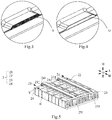
FIG. 1 is a three-dimensional exploded view of a battery box according to this application; -
FIG. 2 is an assembly diagram ofFIG. 1 ; -
FIG. 3 is a locally enlarged view ofFIG. 2 ; -
FIG. 4 is a view similar toFIG. 3 with no sealing member shown; -
FIG. 5 is a three-dimensional diagram of an embodiment of a battery box according to this application, where no box body is shown; -
FIG. 6 is a three-dimensional diagram of another embodiment similar toFIG. 5 , with no box body shown; -
FIG. 7 is a section view along the line A-A ofFIG. 2 ; -
FIG. 8 is a section view of another embodiment similar to that ofFIG. 7 ; -
FIG. 9 is a three-dimensional diagram of an embodiment of a first guide plate; and -
FIG. 10 is a locally enlarged view ofFIG. 9 . - Reference numerals in the accompanying drawings are described as follows:
- C. box body;
- C1. lower box;
- C11. bottom wall;
- C12. first peripheral wall;
- C13. first flange;
- C2. upper box;
- C21. top wall;
- C22. second peripheral wall;
- C23. second flange;
- 1. accommodation space;
- 2. first battery group;
- 21. first battery row;
- B. battery;
- V. explosion-proof valve;
- 211. first explosion-proof valve row;
- 22. first guide plate;
- 221. main body;
- 222. side portion;
- 223. fixed portion;
- 224. stop portion;
- P1. first path;
- 23. first end plate;
- 231. first recess;
- 24. second end plate;
- 241. second recess;
- O. opening;
- S. sealing member;
- b1. first beam;
- b2. second beam;
- 3. second battery group;
- 31. second battery row;
- 311. second explosion-proof valve row;
- 32. second guide plate;
- P2. second path;
- 33. third end plate;
- 331. third recess;
- L. length direction;
- H. height direction; and
- W. width direction.
- The drawings illustrate embodiments of this application, it will be understood that the disclosed embodiments are merely examples of this application, and this application may be implemented in various forms. Therefore, the specific details disclosed in this specification should not be construed as limiting, but are intended only as a basis for the claims and as an illustrative basis for guiding a person of ordinary skill in the art to implement this application in various ways.
- In addition, expressions of indicating directions such as the length direction, the height direction, and the width direction for explaining the operation and construction of each member of a battery box in this embodiment are not absolute but relative. In addition, although these indications are appropriate when the members of the battery box are in the positions shown in the figures, when these positions change, these directions should be interpreted differently to correspond to the changes.
- As shown in
FIG. 1 to FIG. 4 , the battery box according to this application includes: a box body C, afirst battery group 2, and a sealing member S. The battery box may further include asecond battery group 3, a first beam b1, and a second beam b2. - The box body C includes: a lower box C1; and an upper box C2, configured to be sealed and installed on the lower box C1 along a height direction H and enclose an accommodation space 1 with the lower box C1.
- The lower box C1 includes: a bottom wall C11; a first peripheral wall C12, connected to the periphery of the bottom wall C11 and extending in the direction of the upper box C2; and a first flange C13, connected to the first peripheral wall C12 and extending outward along an upper edge of the first peripheral wall C12.
- The upper box C2 includes: a top wall C21; a second peripheral wall C22, connected to the periphery of the top wall C21 and extending in the direction of the lower box C1 direction; and a second flange C23, connected to the second peripheral wall C22 and extending outward along the lower edge of the second peripheral wall C22. The upper box C2 is installed on the lower box C1 along the height direction H, and the second flange C23 of the upper box C2 is sealingly connected with the first flange C13 of the lower box C1.
- Specifically, there are various embodiments of the combination of the
first battery group 2, thesecond battery group 3, the first beam b1 and the second beam b2 in the battery box, which will be described in detail below according to different embodiments. - In a first embodiment, as shown in
FIG. 5 andFIG. 8 , the accommodation space 1 of the box body C accommodates thefirst battery group 2. - The
first battery group 2 includes afirst battery row 21, afirst guide plate 22, afirst end plate 23, and asecond end plate 24. Thefirst guide plate 22 is located above thefirst battery row 21; and thefirst end plate 23 and thesecond end plate 24 are disposed on both sides of thefirst battery row 21 in a width direction W. - The
first battery row 21 includes a plurality of batteries B arranged side by side along the width direction W, an explosion-proof valve V is disposed on the top of each battery, and all the explosion-proof valves V of thefirst battery row 21 form a first explosion-proof valve row 211. Thefirst guide plate 22 is configured to extend along the width direction W and be sealed and disposed above the first explosion-proof valve row 211, and thefirst guide plate 22 and an upper surface of thefirst battery row 21 form a first path P1 extended along the width direction W. - The
first guide plate 22 includes: amain body 221;side portions 222, connected to both sides of themain body 221 along a length direction L and extending along thefirst battery row 21; and fixingportions 223, connected to theside portions 222 and extending outward along the length direction L, where the fixingportions 223 are sealed and fixed on an upper surface of thefirst battery row 21. The fixingportions 223 may be bonded to the upper surface of thefirst battery row 21 via a structural adhesive. Of course, there are another fixing manner, which may be selected according to a specific situation. Thefirst guide plate 22 is formed by integral stamping. Thefirst guide plate 22 is simple to form and easy to install. - The
first end plate 23 is disposed on one side in the width direction W of thefirst battery row 21 and provided with afirst recess 231, thefirst recess 231 is located below thefirst guide plate 22 in a height direction H and communicates with one end of the first path PI, and an opening O is disposed at a position, corresponding to thefirst recess 231, of the box body C. Thesecond end plate 24 is disposed on the other side in the width direction W of thefirst battery row 21 and provided with asecond recess 241, thesecond recess 241 is located below thefirst guide plate 22 in the height direction H and communicates with the other end of the first path PI, and an opening O is disposed at a position, corresponding to thesecond recess 241, of the box body C. Thefirst recess 231 of thefirst end plate 23 is recessed inwardly from a surface on a side facing away from thefirst battery row 21 and extends to an upper surface of thefirst end plate 23 in the height direction H so as to communicate with the first path P1 formed by thefirst guide plate 22. Thesecond end plate 24 has a same structure as thefirst end plate 23. As shown inFIG. 4 , a portion of the second flange C23 of the upper box C2 bulges upward in the height direction H to form a corresponding opening O with the first flange C13 of the lower box C1. Of course, the manner in which the opening O is formed is not limited thereto. For example, a portion of the second flange C23 of the upper box C2 bulges upward in the height direction H and the corresponding portion of the first flange C13 of the lower box C1 bulges downward in the height direction H and the two are engaged to form an opening O; or the corresponding portion of the first flange C13 of the lower box C1 bulges downward in the height direction H and engages with the second flange C23 of the upper box C2 to form an opening O. A specific formation manner can be selected according to a specific situation. Generally, when a battery B fails, gas production inside the battery B will break through the explosion-proof valve V, gas and heat will be rushed out, and some steam also be carried. The gas, heat and steam are collectively referred to as gas production in this specification. Pressure and heat of the gas production are relatively high, while a sealingmember 3 can be damaged by the pressure or high temperature of the gas production, thus opening the opening O. As shown inFIG. 3 , the sealing member S is configured to seal an opening O corresponding to the box body C and be capable of being damaged to open the opening O. It should be noted that the damage of the sealing member S is usually caused by the reason as follows: When the battery B fails, a large amount of gas and heat will be generated inside the battery B; when the gas and heat accumulate to a certain extent, the explosion-proof valve V of the battery B will be broken; the gas and heat that rush out of the explosion-proof valve V will be exported to the opening O along the first path PI, and the sealing member S can be broken out by pressure of the exported gas or melted by the heat, thus causing the sealing member S to be damaged and the opening O to be opened. Preferably, the sealing member S is a bonding adhesive. An adsorption material is provided in the first path P1 formed by thefirst guide plate 22 and the upper surface of thefirst battery row 21. The adsorption material includes a mixture of sodium bicarbonate, ammonium phosphate, and the like. - In this embodiment, as shown in
FIG. 8 , when the explosion-proof valve V of the battery B is broken due to gas production inside the battery B, the part where the explosion-proof valve V of the battery B is broken, the first path P1, thefirst recess 231 of thefirst end plate 23, thesecond recess 241 of thesecond end plate 24, and the opening O of the box body form a communicating exhaust passage. The gas production and heat released through the broken explosion-proof valve V inside the battery B are exported to the openings O on both sides of the box body C through the exhaust passage. When the gas reaches a certain pressure, the gas breaks through the sealing member S or the high-temperature heat carried by the gas melts the sealing member S so as to discharge the gas production and heat to the outside, thus preventing accumulation of the gas production and heat of the battery B in the box body C from causing thermal runaway of another component such as another battery B, preventing spread of thermal runaway, and improving safety performance of the battery box. In addition, the adsorption material can play a role in flame retardant and temperature reduction, and play a role in assisting in reducing thermal runaway diffusion. In addition, the adsorption material can absorb moisture and prevent water vapor from accumulating in the first path P1. - In the first embodiment, the
first battery group 2 has more than twofirst battery rows 21 arranged side by side along a length direction L; there are more than twofirst guide plates 22, and each of thefirst guide plates 22 is sealed and disposed above a corresponding first explosion-proof valve row 211 and forms a first path P1 with an upper surface of a correspondingfirst battery row 21; thefirst end plate 23 has more than twofirst recesses 231, and each of thefirst recesses 231 communicates with one end of a corresponding first path P1; and thesecond end plate 24 has more than twosecond recesses 241, and each of thesecond recesses 241 communicates with the other end of a corresponding first path P1. In this embodiment, twofirst battery rows 21 of thefirst battery group 2 are shown inFIG. 5 , but of course a quantity of thefirst battery rows 21 are not limited to two. The quantity of thefirst battery rows 21 of thefirst battery group 2 may alternatively be one or more than two, and the exhaust path is designed in a same manner regardless of one or more than two. Details are not described herein again. - In a second embodiment (not shown), the difference from the first embodiment is that there are more than two
first battery groups 2 arranged in the length direction L, and the battery box further includes a first beam b1 sandwiched between two adjacentfirst battery groups 2 and dividing an accommodation space 1 of a box body C into more than two subspaces, and each of thefirst battery groups 2 is accommodated in a corresponding subspace. A design of the exhaust path and a function of the exhaust path of eachbattery group 2 are the same as those in the first embodiment. Details are not described herein again. It should be noted that a design of the first beam b 1 can increase overall strength of the box body C. In addition, the subspace divided by the first beam b1 is preferably a sealed space, and each of thefirst battery groups 2 is accommodated in a sealed space. If thermal runaway occurs on a battery B in one of the subspaces, high-temperature or high-pressure gas will not diffuse into the remaining sealed space, further preventing the spread of thermal runaway and further improving safety performance of the battery box. - In a third embodiment, as shown in
FIG. 6 andFIG. 7 , afirst battery group 2 includes afirst battery row 21, afirst guide plate 22, and afirst end plate 23. A battery box further includes asecond battery group 3, where thesecond battery group 3 and afirst battery group 2 are arranged side by side along a width direction W, and thesecond battery group 3 includes asecond battery row 31, asecond guide plate 32, and athird end plate 33. - In this embodiment, as shown in
FIG. 9 and 10 , thefirst guide plate 22 includes: amain body 221;side portions 222, connected to both sides of themain body 221 along a length direction L and extending along thefirst battery row 21; and fixingportions 223, connected to theside portions 222 and extending outward along the length direction L, where the fixingportions 223 are sealed and fixed on an upper surface of thefirst battery row 21. Thefirst guide plate 22 further includes: astop portion 224, disposed at one end of themain body 221 along the width direction W and connected to the ends of themain body 221, theside portions 222, and the fixedportions 223, so that a first path P1 formed by thefirst guide plate 22 and an upper surface of thefirst battery row 21 is closed at one end adjacent to thesecond battery group 3 and exhausts air on the side close to a box body C. In addition, thefirst battery row 21 and thefirst end plate 23 of thefirst battery group 2 are disposed in a same manner as that in the first embodiment. Details are not described herein again. Thestop portion 224 may be welded to the ends of themain body 221, theside portions 222, and the fixingportions 223, or may be integrally formed with themain body 221, theside portions 222, and the fixingportions 223. - The
second battery row 31 includes a plurality of batteries B arranged side by side along the width direction W, an explosion-proof valve V is disposed on the top of each battery B, and all explosion-proof valves V of thesecond battery row 31 form a second explosion-proof valve row 311. - The
second guide plate 32 is configured to extend along the width direction W and be sealed and disposed above the second explosion-proof valve row 311, and thesecond guide plate 32 and an upper surface of thesecond battery row 31 form a second path P2 extended along the width direction W. Thesecond guide plate 32 has a same structure as thefirst guide plate 22. An adsorption material is also provided in the second path P2 formed by thesecond guide plate 32 and the upper surface of thesecond battery row 31. - The
third end plate 33 is disposed on one side in the width direction W of thesecond battery row 31 and provided with athird recess 331, where thethird recess 331 is located below thesecond guide plate 32 in the height direction H and communicates with one end of the second path P2, and an opening O is disposed at a position, corresponding to thethird recess 331, of the box body C. One end, adjacent to thefirst battery group 2, of the second path P2 is closed; and one end, adjacent to thesecond battery group 3, of the first path P1 is closed. - When an explosion-proof valve V of a corresponding battery B is broken by gas production inside the battery B, the gas production and heat of the battery B are discharged to the outside of the box body C through the explosion-proof valve V, a corresponding first path P1 or second path P2, a corresponding
first recess 231 orsecond recess 241, and a corresponding opening O, thus preventing accumulation of the gas production and heat of the battery B in the box body C from causing thermal runaway of another component such as another battery B, preventing spread of thermal runaway, and improving safety performance of the battery box. In addition, the adsorption material can play a role in flame retardant and temperature reduction, and play a role in assisting in reducing thermal runaway diffusion. In addition, the adsorption material can absorb moisture and prevent water vapor from accumulating in the first path P1 or the second path P2. - In a fourth embodiment, as shown in
FIG. 1 , there are more than twofirst battery groups 2 arranged in a length direction L, and there are more than twosecond battery groups 3 arranged in the length direction L. A battery box further includes: a first beam b1, disposed between two adjacentfirst battery groups 2 and two adjacentsecond battery groups 3; and a second beam b2, sandwiched between thefirst battery group 2 and thesecond battery group 3 along a width direction W, where the first beam b1 and the second beam b2 divide an accommodation space 1 into a plurality of subspaces, and each of thefirst battery groups 2 and each of thesecond battery groups 3 are respectively accommodated in corresponding subspaces. Preferably, the subspace is a closed space. This embodiment is different from the third embodiment in the quantity of thefirst battery group 2 and thesecond battery group 3, and a specific exhaust manner is the same as that described above. Details are not described herein again. In addition, the arrangement of the first beam b1 and the second beam b2 improves overall strength of the battery box, and an accommodation space is divided into a plurality of closed subspaces, preventing spread and diffusion of thermal runaway and improving safety performance of the battery box. - The above detailed descriptions describe a plurality of exemplary embodiments, but is not intended to be limited to explicitly disclosed combinations in this specification. Therefore, unless otherwise specified, the various features disclosed in this specification may be combined to form a plurality of additional combinations not shown for the sake of brevity.
Claims (10)
- A battery box, comprising: a box body (C) comprising a closed accommodation space (1); and a first battery group (2) accommodated in the accommodation space (1), wherein the first battery group (2) comprises:a first battery row (21), wherein the first battery row (21) comprises a plurality of batteries (B) arranged side by side along a width direction (W), an explosion-proof valve (V) is disposed on the top of each battery (B), and all explosion-proof valves (V) of the first battery row (21) form a first explosion-proof valve row (211);a first guide plate (22), configured to extend along the width direction (W) and be sealed and disposed above the first explosion-proof valve row (211), wherein the first guide plate (22) and an upper surface of the first battery row (21) form a first path (P1) extended along the width direction (W); anda first end plate (23), disposed on one side in the width direction (W) of the first battery row (21) and provided with a first recess (231), wherein the first recess (231) is located below the first guide plate (22) in a height direction (H) and communicates with one end of the first path (PI), and an opening (O) is disposed at a position, corresponding to the first recess (231), of the box body (C), whereinthe battery box further comprises: a sealing member (S), configured to seal an opening (O) corresponding to the box body (C) and be capable of being damaged to open the opening (O).
- The battery box according to claim 1, wherein the first battery group (2) further comprises:
a second end plate (24), disposed on the other side in the width direction (W) of the first battery row (21) and provided with a second recess (241), wherein the second recess (241) is located below the first guide plate (22) in the height direction (H) and communicates with the other end of the first path (PI), and an opening (O) is disposed at a position, corresponding to the second recess (241), of the box body (C). - The battery box according to claim 2, wherein
the first battery group (2) has more than two first battery rows (21) arranged side by side along a length direction (L); a quantity of the first guide plates (22) is more than two, and each of the first guide plates (22) is sealed and disposed above a corresponding first explosion-proof valve row (211) and forms a first path (P1) with an upper surface of a corresponding first battery row (21); the first end plate (23) has more than two first recesses (231), and each of the first recesses (231) communicates with one end of a corresponding first path (PI); and the second end plate (24) has more than two second recesses (241), and each of the second recesses (241) communicates with the other end of a corresponding first path (P1). - The battery box according to claim 1, wherein the battery box further comprises:a second battery group (3), wherein the second battery group (3) and the first battery group (2) are arranged side by side along the width direction (W), and the second battery group (3) comprises:a second battery row (31), wherein the second battery row (31) comprises a plurality of batteries (B) arranged side by side along the width direction (W), an explosion-proof valve (V) is disposed on the top of each battery (B), and all explosion-proof valves (V) of the second battery row (31) form a second explosion-proof valve row (311);a second guide plate (32), configured to extend along the width direction (W) and be sealed and disposed above the second explosion-proof valve row (311), wherein the second guide plate (32) and an upper surface of the second battery row (31) form a second path (P2) extended along the width direction (W); anda third end plate (33), disposed on one side in the width direction (W) of the second battery row (31) and provided with a third recess (331), wherein the third recess (331) is located below the second guide plate (32) in the height direction (H) and communicates with one end of the second path (P2), and an opening (O) is disposed at a position, corresponding to the third recess (331), of the box body (C), whereinone end, adjacent to the first battery group (2), of the second path (P2) is closed; and one end, adjacent to the second battery group (3), of the first path (P1) is closed.
- The battery box according to claim 4, wherein
a quantity of the first battery groups (2) arranged in the length direction (L) is more than two, and a quantity of the second battery groups (3) arranged in the length direction (L)is more than two; and
the battery box further comprises:a first beam (b1), disposed between two adjacent first battery groups (2) and two adjacent second battery groups (3); anda second beam (b2), sandwiched between the first battery group (2) and the second battery group (3) along the width direction (W), wherein the first beam (b1) and the second beam (b2) divide the accommodation space (1) into a plurality of subspaces, and each of the first battery groups (2) and each of the second battery groups (3) are respectively accommodated in corresponding subspaces. - The battery box according to claim 1, wherein
the first guide plate (22) comprises: a main body (221); side portions (222), connected to both sides of the main body (221) along the length direction (L) and extending along the first battery row (21); and fixing portions (223), connected to the side portions (222) and extending outward along the length direction (L), wherein the fixing portions (223) are sealed and fixed on an upper surface of the first battery row (21). - The battery box according to claim 6, wherein the first guide plate (22) further comprises: a stop portion (224), disposed at one end of the main body (221) along the width direction (W) and connected to the ends of the main body (221), the side portions (222) and the fixed portions (223).
- The battery box according to claim 1, wherein
an adsorption material is provided in the first path (P1) formed by the first guide plate (22) and the upper surface of the first battery row (21). - The battery box according to claim 1, wherein
the box body (C) comprises: a lower box body (C1); and an upper box body (C2), configured to be sealed and installed on the lower box body (C1) along the height direction (H) and enclose the accommodation space (1) with the lower box body (C1), wherein
the lower box (C1) comprises: a bottom wall (C11); a first peripheral wall (C12), connected to the periphery of the bottom wall (C11) and extending in the direction of the upper box (C2); and a first flange (C13), connected to the first peripheral wall (C12) and extending outward along an upper edge of the first peripheral wall (C12); and
the upper box (C2) comprises: a top wall (C21); a second peripheral wall (C22), connected to the periphery of the top wall (C21) and extending in the direction of the lower box (C1); and a second flange (C23), connected to the second peripheral wall (C22) and extending outward along the lower edge of the second peripheral wall (C22), wherein
the upper box (C2) is installed on the lower box (C1) along the height direction (H), and the second flange (C23) of the upper box (C2) is sealingly connected with the first flange (C13) of the lower box (C1). - The battery box according to claim 9, wherein
a portion of the second flange (C23) of the upper box (C2) bulges upward in the height direction (H) to form a corresponding opening (O) with the first flange (C13) of the lower box (C1).
Applications Claiming Priority (2)
| Application Number | Priority Date | Filing Date | Title |
|---|---|---|---|
| CN201822224310.8U CN209183604U (en) | 2018-12-27 | 2018-12-27 | Battery case |
| PCT/CN2019/125990 WO2020135152A1 (en) | 2018-12-27 | 2019-12-17 | Battery box |
Publications (3)
| Publication Number | Publication Date |
|---|---|
| EP3799150A1 true EP3799150A1 (en) | 2021-03-31 |
| EP3799150A4 EP3799150A4 (en) | 2021-10-06 |
| EP3799150B1 EP3799150B1 (en) | 2022-10-26 |
Family
ID=67378022
Family Applications (1)
| Application Number | Title | Priority Date | Filing Date |
|---|---|---|---|
| EP19903399.4A Active EP3799150B1 (en) | 2018-12-27 | 2019-12-17 | Battery box |
Country Status (4)
| Country | Link |
|---|---|
| US (1) | US11949114B2 (en) |
| EP (1) | EP3799150B1 (en) |
| CN (1) | CN209183604U (en) |
| WO (1) | WO2020135152A1 (en) |
Cited By (15)
| Publication number | Priority date | Publication date | Assignee | Title |
|---|---|---|---|---|
| EP3920255A4 (en) * | 2019-10-15 | 2022-06-08 | Contemporary Amperex Technology Co., Limited | Battery pack and vehicle |
| EP4084191A4 (en) * | 2020-04-01 | 2023-08-09 | LG Energy Solution, Ltd. | Battery module including gas breaking structure |
| EP4228069A1 (en) * | 2022-02-14 | 2023-08-16 | Samsung SDI Co., Ltd. | Battery pack, electric vehicle and method for assembling a battery pack |
| EP4181301A4 (en) * | 2021-05-17 | 2024-07-24 | LG Energy Solution, Ltd. | BATTERY PACK HAVING A GAS DISCHARGE PATH |
| US12230826B2 (en) | 2022-03-23 | 2025-02-18 | Ford Global Technologies, Llc | Methods for assembling traction battery packs |
| US12275298B2 (en) | 2022-03-23 | 2025-04-15 | Ford Global Technologies, Llc | Traction battery packs with cell-to-pack battery systems housed within irregularly shaped enclosures |
| US12374750B2 (en) | 2022-03-23 | 2025-07-29 | Ford Global Technologies, Llc | Traction battery pack assembling method |
| US12424695B2 (en) | 2022-03-23 | 2025-09-23 | Ford Global Technologies, Llc | Retention assemblies for traction battery packs with cell-to-pack battery systems |
| US12479327B2 (en) | 2022-03-23 | 2025-11-25 | Ford Global Technologies, Llc | Traction battery pack cell stack removal method and battery pack assembly |
| US12506215B2 (en) | 2022-03-23 | 2025-12-23 | Ford Global Technologies, Llc | Enclosure cover attachment configurations for traction battery packs with cell-to-pack battery systems |
| US12525637B2 (en) | 2022-03-23 | 2026-01-13 | Ford Global Technologies, Llc | Traction battery pack assembling method |
| US12567642B2 (en) | 2022-03-23 | 2026-03-03 | Ford Global Technologies, Llc | Shim systems for traction battery packs |
| US12603373B2 (en) | 2022-03-23 | 2026-04-14 | Ford Global Technologies, Llc | Traction battery pack assembling method |
| US12633564B2 (en) | 2022-03-23 | 2026-05-19 | Ford Global Technologies, Llc | Battery lift and transfer solutions for assembling traction battery packs |
| US12651799B2 (en) | 2022-03-23 | 2026-06-09 | Ford Global Technologies, Llc | Traction battery pack assembling method |
Families Citing this family (19)
| Publication number | Priority date | Publication date | Assignee | Title |
|---|---|---|---|---|
| CN209183604U (en) | 2018-12-27 | 2019-07-30 | 宁德时代新能源科技股份有限公司 | Battery case |
| CN112331997B (en) * | 2019-10-15 | 2021-11-12 | 宁德时代新能源科技股份有限公司 | Battery pack and vehicle |
| US20230092773A1 (en) * | 2020-02-18 | 2023-03-23 | Asahi Kasei Kabushiki Kaisha | Lithium ion battery module |
| CN113594636B (en) | 2020-04-30 | 2024-10-18 | 宁德时代新能源科技股份有限公司 | Battery, device, and battery manufacturing method and equipment |
| WO2022021135A1 (en) | 2020-07-29 | 2022-02-03 | 宁德时代新能源科技股份有限公司 | Battery module, battery pack, apparatus, and method and device for manufacturing battery module |
| WO2022052093A1 (en) * | 2020-09-14 | 2022-03-17 | 宁德时代新能源科技股份有限公司 | Battery, electric device, and manufacturing method and system for battery |
| JP7674361B2 (en) * | 2020-09-30 | 2025-05-09 | 香港時代新能源科技有限公司 | Battery, device, battery manufacturing method and manufacturing device |
| CN115943522B (en) | 2020-09-30 | 2025-02-18 | 宁德时代新能源科技股份有限公司 | Battery, device, method for preparing battery, and device for preparing battery |
| WO2022067808A1 (en) | 2020-09-30 | 2022-04-07 | 宁德时代新能源科技股份有限公司 | Battery, device, and battery fabrication method and fabrication apparatus |
| WO2022104547A1 (en) | 2020-11-17 | 2022-05-27 | 宁德时代新能源科技股份有限公司 | Battery, device using battery, and method and device for preparing battery |
| WO2022133959A1 (en) | 2020-12-24 | 2022-06-30 | 宁德时代新能源科技股份有限公司 | Battery module and manufacturing method and device therefor, and battery pack and electrical apparatus |
| CN112787020B (en) * | 2021-03-11 | 2025-04-25 | 蔚来汽车科技(安徽)有限公司 | Power battery pack with thermal insulation component |
| CN113113740B (en) * | 2021-03-26 | 2026-04-10 | 厦门海辰储能科技股份有限公司 | A battery module and energy storage system |
| CN113594623B (en) * | 2021-08-11 | 2023-05-30 | 蜂巢能源科技股份有限公司 | Explosion-proof valve for battery pack |
| CN113659279B (en) * | 2021-08-13 | 2023-05-12 | 蜂巢能源科技股份有限公司 | Explosion-proof device for battery pack and battery pack |
| KR20240125030A (en) * | 2022-07-22 | 2024-08-19 | 컨템포러리 엠퍼렉스 테크놀로지 씨오., 리미티드 | Batteries and electrical devices |
| CN115693008A (en) * | 2022-11-07 | 2023-02-03 | 中创新航科技股份有限公司 | Battery pack |
| CN117080674B (en) * | 2023-10-17 | 2024-01-26 | 厦门海辰储能科技股份有限公司 | Battery pack and electric equipment |
| CN222927678U (en) * | 2024-07-22 | 2025-05-30 | 惠州亿纬锂能股份有限公司 | Integrated battery pack and electric automobile |
Family Cites Families (17)
| Publication number | Priority date | Publication date | Assignee | Title |
|---|---|---|---|---|
| US20030232236A1 (en) * | 2002-06-14 | 2003-12-18 | Mitchell Porter H. | Battery package vent |
| US20050147874A1 (en) * | 2003-12-10 | 2005-07-07 | Johnson Controls Technolgy Company | Venting system for battery |
| KR100888283B1 (en) * | 2006-10-23 | 2009-03-10 | 주식회사 엘지화학 | Secondary battery pack with excellent structural stability |
| CN101960645B (en) * | 2008-09-26 | 2012-09-26 | 松下电器产业株式会社 | Lead acid battery manufacturing method and lead acid battery |
| DE102009018787A1 (en) * | 2009-04-24 | 2010-10-28 | Akasol Engineering Gmbh | battery module |
| US8734978B2 (en) | 2009-11-05 | 2014-05-27 | Samsung Sdi Co., Ltd. | Battery pack |
| EP2325922B1 (en) * | 2009-11-19 | 2012-05-09 | SB LiMotive Co., Ltd. | Battery pack |
| WO2012014348A1 (en) * | 2010-07-28 | 2012-02-02 | パナソニック株式会社 | Cell module and cell pack |
| JP5594592B2 (en) * | 2010-09-30 | 2014-09-24 | 株式会社Gsユアサ | Battery module and battery pack |
| JP5703368B2 (en) * | 2011-03-25 | 2015-04-15 | 日立オートモティブシステムズ株式会社 | Battery block and power supply device |
| CN203466244U (en) * | 2013-09-24 | 2014-03-05 | 宁德新能源科技有限公司 | Power battery module and safety protection device thereof |
| KR20150066077A (en) * | 2013-12-06 | 2015-06-16 | 삼성에스디아이 주식회사 | Battery module |
| JP6245038B2 (en) * | 2014-03-31 | 2017-12-13 | 株式会社Gsユアサ | Power storage device |
| CN204651372U (en) * | 2015-06-05 | 2015-09-16 | 宁德时代新能源科技有限公司 | For the cover assembly of battery modules |
| DE102016118753A1 (en) * | 2016-10-04 | 2018-04-05 | Johnson Controls Advanced Power Solutions Gmbh | ENERGY STORAGE SYSTEM |
| US20180138478A1 (en) * | 2016-11-14 | 2018-05-17 | Anhui Xinen Technology Co., Ltd. | Alleviating explosion propagation in a battery module |
| CN209183604U (en) * | 2018-12-27 | 2019-07-30 | 宁德时代新能源科技股份有限公司 | Battery case |
-
2018
- 2018-12-27 CN CN201822224310.8U patent/CN209183604U/en active Active
-
2019
- 2019-12-17 EP EP19903399.4A patent/EP3799150B1/en active Active
- 2019-12-17 WO PCT/CN2019/125990 patent/WO2020135152A1/en not_active Ceased
-
2020
- 2020-12-17 US US17/125,998 patent/US11949114B2/en active Active
Cited By (15)
| Publication number | Priority date | Publication date | Assignee | Title |
|---|---|---|---|---|
| EP3920255A4 (en) * | 2019-10-15 | 2022-06-08 | Contemporary Amperex Technology Co., Limited | Battery pack and vehicle |
| EP4084191A4 (en) * | 2020-04-01 | 2023-08-09 | LG Energy Solution, Ltd. | Battery module including gas breaking structure |
| EP4181301A4 (en) * | 2021-05-17 | 2024-07-24 | LG Energy Solution, Ltd. | BATTERY PACK HAVING A GAS DISCHARGE PATH |
| EP4228069A1 (en) * | 2022-02-14 | 2023-08-16 | Samsung SDI Co., Ltd. | Battery pack, electric vehicle and method for assembling a battery pack |
| US12374750B2 (en) | 2022-03-23 | 2025-07-29 | Ford Global Technologies, Llc | Traction battery pack assembling method |
| US12275298B2 (en) | 2022-03-23 | 2025-04-15 | Ford Global Technologies, Llc | Traction battery packs with cell-to-pack battery systems housed within irregularly shaped enclosures |
| US12230826B2 (en) | 2022-03-23 | 2025-02-18 | Ford Global Technologies, Llc | Methods for assembling traction battery packs |
| US12424695B2 (en) | 2022-03-23 | 2025-09-23 | Ford Global Technologies, Llc | Retention assemblies for traction battery packs with cell-to-pack battery systems |
| US12479327B2 (en) | 2022-03-23 | 2025-11-25 | Ford Global Technologies, Llc | Traction battery pack cell stack removal method and battery pack assembly |
| US12506215B2 (en) | 2022-03-23 | 2025-12-23 | Ford Global Technologies, Llc | Enclosure cover attachment configurations for traction battery packs with cell-to-pack battery systems |
| US12525637B2 (en) | 2022-03-23 | 2026-01-13 | Ford Global Technologies, Llc | Traction battery pack assembling method |
| US12567642B2 (en) | 2022-03-23 | 2026-03-03 | Ford Global Technologies, Llc | Shim systems for traction battery packs |
| US12603373B2 (en) | 2022-03-23 | 2026-04-14 | Ford Global Technologies, Llc | Traction battery pack assembling method |
| US12633564B2 (en) | 2022-03-23 | 2026-05-19 | Ford Global Technologies, Llc | Battery lift and transfer solutions for assembling traction battery packs |
| US12651799B2 (en) | 2022-03-23 | 2026-06-09 | Ford Global Technologies, Llc | Traction battery pack assembling method |
Also Published As
| Publication number | Publication date |
|---|---|
| WO2020135152A1 (en) | 2020-07-02 |
| EP3799150A4 (en) | 2021-10-06 |
| CN209183604U (en) | 2019-07-30 |
| US20210104798A1 (en) | 2021-04-08 |
| US11949114B2 (en) | 2024-04-02 |
| EP3799150B1 (en) | 2022-10-26 |
Similar Documents
| Publication | Publication Date | Title |
|---|---|---|
| US11949114B2 (en) | Battery box | |
| JP7513710B2 (en) | Battery pack and vehicle | |
| CN112331981B (en) | Battery pack and vehicle | |
| CN111668408B (en) | Battery trays, power battery packs and vehicles | |
| CN110444835B (en) | Battery packs and vehicles | |
| CN216793860U (en) | Battery module and have its battery package | |
| CN219350557U (en) | Battery tray and battery pack | |
| CN221239698U (en) | Battery pack | |
| WO2024109418A1 (en) | Battery pack and automobile | |
| CN213752873U (en) | Battery Cases and Battery Packs | |
| WO2024175005A1 (en) | Battery and power device | |
| CN111668423A (en) | Battery modules, power battery packs and vehicles | |
| CN221126103U (en) | Battery pack and electrical equipment | |
| CN220914389U (en) | Battery cell cover plate, battery cell and battery pack | |
| CN220544136U (en) | Battery pack trays, battery packs and vehicles | |
| CN219717169U (en) | Battery pack | |
| WO2025246779A1 (en) | Battery module having pressure relief and explosion-proof functions, and battery box | |
| CN221102295U (en) | Battery pack | |
| CN220797003U (en) | Battery package lid and have its battery package | |
| CN220382218U (en) | Box components and battery packs | |
| CN216529224U (en) | A module protective cover, a battery module and a battery pack | |
| CN219937241U (en) | Battery pack box and battery pack | |
| CN219123322U (en) | Battery module and battery pack with thermal runaway protection function | |
| CN224217660U (en) | Battery pack and power utilization device | |
| CN219832879U (en) | Battery device |
Legal Events
| Date | Code | Title | Description |
|---|---|---|---|
| STAA | Information on the status of an ep patent application or granted ep patent |
Free format text: STATUS: THE INTERNATIONAL PUBLICATION HAS BEEN MADE |
|
| PUAI | Public reference made under article 153(3) epc to a published international application that has entered the european phase |
Free format text: ORIGINAL CODE: 0009012 |
|
| STAA | Information on the status of an ep patent application or granted ep patent |
Free format text: STATUS: REQUEST FOR EXAMINATION WAS MADE |
|
| 17P | Request for examination filed |
Effective date: 20201218 |
|
| AK | Designated contracting states |
Kind code of ref document: A1 Designated state(s): AL AT BE BG CH CY CZ DE DK EE ES FI FR GB GR HR HU IE IS IT LI LT LU LV MC MK MT NL NO PL PT RO RS SE SI SK SM TR |
|
| AX | Request for extension of the european patent |
Extension state: BA ME |
|
| REG | Reference to a national code |
Ref country code: DE Ref legal event code: R079 Ref document number: 602019021274 Country of ref document: DE Free format text: PREVIOUS MAIN CLASS: H01M0002100000 Ipc: H01M0010613000 |
|
| A4 | Supplementary search report drawn up and despatched |
Effective date: 20210906 |
|
| RIC1 | Information provided on ipc code assigned before grant |
Ipc: H01M 10/625 20140101ALI20210901BHEP Ipc: H01M 10/613 20140101AFI20210901BHEP |
|
| STAA | Information on the status of an ep patent application or granted ep patent |
Free format text: STATUS: EXAMINATION IS IN PROGRESS |
|
| 17Q | First examination report despatched |
Effective date: 20220104 |
|
| DAV | Request for validation of the european patent (deleted) | ||
| DAX | Request for extension of the european patent (deleted) | ||
| GRAP | Despatch of communication of intention to grant a patent |
Free format text: ORIGINAL CODE: EPIDOSNIGR1 |
|
| STAA | Information on the status of an ep patent application or granted ep patent |
Free format text: STATUS: GRANT OF PATENT IS INTENDED |
|
| INTG | Intention to grant announced |
Effective date: 20220519 |
|
| GRAS | Grant fee paid |
Free format text: ORIGINAL CODE: EPIDOSNIGR3 |
|
| GRAA | (expected) grant |
Free format text: ORIGINAL CODE: 0009210 |
|
| STAA | Information on the status of an ep patent application or granted ep patent |
Free format text: STATUS: THE PATENT HAS BEEN GRANTED |
|
| AK | Designated contracting states |
Kind code of ref document: B1 Designated state(s): AL AT BE BG CH CY CZ DE DK EE ES FI FR GB GR HR HU IE IS IT LI LT LU LV MC MK MT NL NO PL PT RO RS SE SI SK SM TR |
|
| REG | Reference to a national code |
Ref country code: GB Ref legal event code: FG4D |
|
| REG | Reference to a national code |
Ref country code: CH Ref legal event code: EP |
|
| REG | Reference to a national code |
Ref country code: DE Ref legal event code: R096 Ref document number: 602019021274 Country of ref document: DE |
|
| REG | Reference to a national code |
Ref country code: AT Ref legal event code: REF Ref document number: 1527716 Country of ref document: AT Kind code of ref document: T Effective date: 20221115 |
|
| REG | Reference to a national code |
Ref country code: IE Ref legal event code: FG4D |
|
| REG | Reference to a national code |
Ref country code: LT Ref legal event code: MG9D |
|
| REG | Reference to a national code |
Ref country code: NL Ref legal event code: MP Effective date: 20221026 |
|
| REG | Reference to a national code |
Ref country code: AT Ref legal event code: MK05 Ref document number: 1527716 Country of ref document: AT Kind code of ref document: T Effective date: 20221026 |
|
| PG25 | Lapsed in a contracting state [announced via postgrant information from national office to epo] |
Ref country code: NL Free format text: LAPSE BECAUSE OF FAILURE TO SUBMIT A TRANSLATION OF THE DESCRIPTION OR TO PAY THE FEE WITHIN THE PRESCRIBED TIME-LIMIT Effective date: 20221026 |
|
| PG25 | Lapsed in a contracting state [announced via postgrant information from national office to epo] |
Ref country code: SE Free format text: LAPSE BECAUSE OF FAILURE TO SUBMIT A TRANSLATION OF THE DESCRIPTION OR TO PAY THE FEE WITHIN THE PRESCRIBED TIME-LIMIT Effective date: 20221026 Ref country code: PT Free format text: LAPSE BECAUSE OF FAILURE TO SUBMIT A TRANSLATION OF THE DESCRIPTION OR TO PAY THE FEE WITHIN THE PRESCRIBED TIME-LIMIT Effective date: 20230227 Ref country code: NO Free format text: LAPSE BECAUSE OF FAILURE TO SUBMIT A TRANSLATION OF THE DESCRIPTION OR TO PAY THE FEE WITHIN THE PRESCRIBED TIME-LIMIT Effective date: 20230126 Ref country code: LT Free format text: LAPSE BECAUSE OF FAILURE TO SUBMIT A TRANSLATION OF THE DESCRIPTION OR TO PAY THE FEE WITHIN THE PRESCRIBED TIME-LIMIT Effective date: 20221026 Ref country code: FI Free format text: LAPSE BECAUSE OF FAILURE TO SUBMIT A TRANSLATION OF THE DESCRIPTION OR TO PAY THE FEE WITHIN THE PRESCRIBED TIME-LIMIT Effective date: 20221026 Ref country code: ES Free format text: LAPSE BECAUSE OF FAILURE TO SUBMIT A TRANSLATION OF THE DESCRIPTION OR TO PAY THE FEE WITHIN THE PRESCRIBED TIME-LIMIT Effective date: 20221026 Ref country code: AT Free format text: LAPSE BECAUSE OF FAILURE TO SUBMIT A TRANSLATION OF THE DESCRIPTION OR TO PAY THE FEE WITHIN THE PRESCRIBED TIME-LIMIT Effective date: 20221026 |
|
| PG25 | Lapsed in a contracting state [announced via postgrant information from national office to epo] |
Ref country code: RS Free format text: LAPSE BECAUSE OF FAILURE TO SUBMIT A TRANSLATION OF THE DESCRIPTION OR TO PAY THE FEE WITHIN THE PRESCRIBED TIME-LIMIT Effective date: 20221026 Ref country code: PL Free format text: LAPSE BECAUSE OF FAILURE TO SUBMIT A TRANSLATION OF THE DESCRIPTION OR TO PAY THE FEE WITHIN THE PRESCRIBED TIME-LIMIT Effective date: 20221026 Ref country code: LV Free format text: LAPSE BECAUSE OF FAILURE TO SUBMIT A TRANSLATION OF THE DESCRIPTION OR TO PAY THE FEE WITHIN THE PRESCRIBED TIME-LIMIT Effective date: 20221026 Ref country code: IS Free format text: LAPSE BECAUSE OF FAILURE TO SUBMIT A TRANSLATION OF THE DESCRIPTION OR TO PAY THE FEE WITHIN THE PRESCRIBED TIME-LIMIT Effective date: 20230226 Ref country code: HR Free format text: LAPSE BECAUSE OF FAILURE TO SUBMIT A TRANSLATION OF THE DESCRIPTION OR TO PAY THE FEE WITHIN THE PRESCRIBED TIME-LIMIT Effective date: 20221026 Ref country code: GR Free format text: LAPSE BECAUSE OF FAILURE TO SUBMIT A TRANSLATION OF THE DESCRIPTION OR TO PAY THE FEE WITHIN THE PRESCRIBED TIME-LIMIT Effective date: 20230127 |
|
| P01 | Opt-out of the competence of the unified patent court (upc) registered |
Effective date: 20230516 |
|
| REG | Reference to a national code |
Ref country code: DE Ref legal event code: R097 Ref document number: 602019021274 Country of ref document: DE |
|
| PG25 | Lapsed in a contracting state [announced via postgrant information from national office to epo] |
Ref country code: SM Free format text: LAPSE BECAUSE OF FAILURE TO SUBMIT A TRANSLATION OF THE DESCRIPTION OR TO PAY THE FEE WITHIN THE PRESCRIBED TIME-LIMIT Effective date: 20221026 Ref country code: RO Free format text: LAPSE BECAUSE OF FAILURE TO SUBMIT A TRANSLATION OF THE DESCRIPTION OR TO PAY THE FEE WITHIN THE PRESCRIBED TIME-LIMIT Effective date: 20221026 Ref country code: EE Free format text: LAPSE BECAUSE OF FAILURE TO SUBMIT A TRANSLATION OF THE DESCRIPTION OR TO PAY THE FEE WITHIN THE PRESCRIBED TIME-LIMIT Effective date: 20221026 Ref country code: DK Free format text: LAPSE BECAUSE OF FAILURE TO SUBMIT A TRANSLATION OF THE DESCRIPTION OR TO PAY THE FEE WITHIN THE PRESCRIBED TIME-LIMIT Effective date: 20221026 Ref country code: CZ Free format text: LAPSE BECAUSE OF FAILURE TO SUBMIT A TRANSLATION OF THE DESCRIPTION OR TO PAY THE FEE WITHIN THE PRESCRIBED TIME-LIMIT Effective date: 20221026 |
|
| REG | Reference to a national code |
Ref country code: CH Ref legal event code: PL |
|
| REG | Reference to a national code |
Ref country code: BE Ref legal event code: MM Effective date: 20221231 |
|
| PG25 | Lapsed in a contracting state [announced via postgrant information from national office to epo] |
Ref country code: SK Free format text: LAPSE BECAUSE OF FAILURE TO SUBMIT A TRANSLATION OF THE DESCRIPTION OR TO PAY THE FEE WITHIN THE PRESCRIBED TIME-LIMIT Effective date: 20221026 Ref country code: LU Free format text: LAPSE BECAUSE OF NON-PAYMENT OF DUE FEES Effective date: 20221217 Ref country code: AL Free format text: LAPSE BECAUSE OF FAILURE TO SUBMIT A TRANSLATION OF THE DESCRIPTION OR TO PAY THE FEE WITHIN THE PRESCRIBED TIME-LIMIT Effective date: 20221026 |
|
| PLBE | No opposition filed within time limit |
Free format text: ORIGINAL CODE: 0009261 |
|
| STAA | Information on the status of an ep patent application or granted ep patent |
Free format text: STATUS: NO OPPOSITION FILED WITHIN TIME LIMIT |
|
| 26N | No opposition filed |
Effective date: 20230727 |
|
| PG25 | Lapsed in a contracting state [announced via postgrant information from national office to epo] |
Ref country code: LI Free format text: LAPSE BECAUSE OF NON-PAYMENT OF DUE FEES Effective date: 20221231 Ref country code: IE Free format text: LAPSE BECAUSE OF NON-PAYMENT OF DUE FEES Effective date: 20221217 Ref country code: CH Free format text: LAPSE BECAUSE OF NON-PAYMENT OF DUE FEES Effective date: 20221231 |
|
| PG25 | Lapsed in a contracting state [announced via postgrant information from national office to epo] |
Ref country code: SI Free format text: LAPSE BECAUSE OF FAILURE TO SUBMIT A TRANSLATION OF THE DESCRIPTION OR TO PAY THE FEE WITHIN THE PRESCRIBED TIME-LIMIT Effective date: 20221026 Ref country code: BE Free format text: LAPSE BECAUSE OF NON-PAYMENT OF DUE FEES Effective date: 20221231 |
|
| PG25 | Lapsed in a contracting state [announced via postgrant information from national office to epo] |
Ref country code: CY Free format text: LAPSE BECAUSE OF FAILURE TO SUBMIT A TRANSLATION OF THE DESCRIPTION OR TO PAY THE FEE WITHIN THE PRESCRIBED TIME-LIMIT Effective date: 20221026 |
|
| PG25 | Lapsed in a contracting state [announced via postgrant information from national office to epo] |
Ref country code: MK Free format text: LAPSE BECAUSE OF FAILURE TO SUBMIT A TRANSLATION OF THE DESCRIPTION OR TO PAY THE FEE WITHIN THE PRESCRIBED TIME-LIMIT Effective date: 20221026 Ref country code: IT Free format text: LAPSE BECAUSE OF FAILURE TO SUBMIT A TRANSLATION OF THE DESCRIPTION OR TO PAY THE FEE WITHIN THE PRESCRIBED TIME-LIMIT Effective date: 20221026 Ref country code: HU Free format text: LAPSE BECAUSE OF FAILURE TO SUBMIT A TRANSLATION OF THE DESCRIPTION OR TO PAY THE FEE WITHIN THE PRESCRIBED TIME-LIMIT; INVALID AB INITIO Effective date: 20191217 |
|
| PG25 | Lapsed in a contracting state [announced via postgrant information from national office to epo] |
Ref country code: MC Free format text: LAPSE BECAUSE OF FAILURE TO SUBMIT A TRANSLATION OF THE DESCRIPTION OR TO PAY THE FEE WITHIN THE PRESCRIBED TIME-LIMIT Effective date: 20221026 |
|
| PG25 | Lapsed in a contracting state [announced via postgrant information from national office to epo] |
Ref country code: MC Free format text: LAPSE BECAUSE OF FAILURE TO SUBMIT A TRANSLATION OF THE DESCRIPTION OR TO PAY THE FEE WITHIN THE PRESCRIBED TIME-LIMIT Effective date: 20221026 |
|
| PG25 | Lapsed in a contracting state [announced via postgrant information from national office to epo] |
Ref country code: BG Free format text: LAPSE BECAUSE OF FAILURE TO SUBMIT A TRANSLATION OF THE DESCRIPTION OR TO PAY THE FEE WITHIN THE PRESCRIBED TIME-LIMIT Effective date: 20221026 |
|
| REG | Reference to a national code |
Ref country code: DE Ref legal event code: R081 Ref document number: 602019021274 Country of ref document: DE Owner name: CONTEMPORARY AMPEREX TECHNOLOGY (HONG KONG) LI, HK Free format text: FORMER OWNER: CONTEMPORARY AMPEREX TECHNOLOGY CO., LIMITED, NINGDE, FUJIAN, CN |
|
| REG | Reference to a national code |
Ref country code: GB Ref legal event code: 732E Free format text: REGISTERED BETWEEN 20240815 AND 20240821 |
|
| PG25 | Lapsed in a contracting state [announced via postgrant information from national office to epo] |
Ref country code: MT Free format text: LAPSE BECAUSE OF FAILURE TO SUBMIT A TRANSLATION OF THE DESCRIPTION OR TO PAY THE FEE WITHIN THE PRESCRIBED TIME-LIMIT Effective date: 20221026 |
|
| PG25 | Lapsed in a contracting state [announced via postgrant information from national office to epo] |
Ref country code: TR Free format text: LAPSE BECAUSE OF FAILURE TO SUBMIT A TRANSLATION OF THE DESCRIPTION OR TO PAY THE FEE WITHIN THE PRESCRIBED TIME-LIMIT Effective date: 20221026 |
|
| PGFP | Annual fee paid to national office [announced via postgrant information from national office to epo] |
Ref country code: DE Payment date: 20250930 Year of fee payment: 7 |
|
| PGFP | Annual fee paid to national office [announced via postgrant information from national office to epo] |
Ref country code: GB Payment date: 20251001 Year of fee payment: 7 |
|
| PGFP | Annual fee paid to national office [announced via postgrant information from national office to epo] |
Ref country code: FR Payment date: 20251008 Year of fee payment: 7 |