EP3799149A1 - Battery cushion pad and molding method, and battery module and molding method - Google Patents
Battery cushion pad and molding method, and battery module and molding method Download PDFInfo
- Publication number
- EP3799149A1 EP3799149A1 EP19874907.9A EP19874907A EP3799149A1 EP 3799149 A1 EP3799149 A1 EP 3799149A1 EP 19874907 A EP19874907 A EP 19874907A EP 3799149 A1 EP3799149 A1 EP 3799149A1
- Authority
- EP
- European Patent Office
- Prior art keywords
- pore
- battery
- battery cushion
- pouch
- cushion
- Prior art date
- Legal status (The legal status is an assumption and is not a legal conclusion. Google has not performed a legal analysis and makes no representation as to the accuracy of the status listed.)
- Granted
Links
Images


Classifications
-
- H—ELECTRICITY
- H01—ELECTRIC ELEMENTS
- H01M—PROCESSES OR MEANS, e.g. BATTERIES, FOR THE DIRECT CONVERSION OF CHEMICAL ENERGY INTO ELECTRICAL ENERGY
- H01M50/00—Constructional details or processes of manufacture of the non-active parts of electrochemical cells other than fuel cells, e.g. hybrid cells
- H01M50/20—Mountings; Secondary casings or frames; Racks, modules or packs; Suspension devices; Shock absorbers; Transport or carrying devices; Holders
- H01M50/204—Racks, modules or packs for multiple batteries or multiple cells
- H01M50/207—Racks, modules or packs for multiple batteries or multiple cells characterised by their shape
- H01M50/209—Racks, modules or packs for multiple batteries or multiple cells characterised by their shape adapted for prismatic or rectangular cells
-
- H—ELECTRICITY
- H01—ELECTRIC ELEMENTS
- H01M—PROCESSES OR MEANS, e.g. BATTERIES, FOR THE DIRECT CONVERSION OF CHEMICAL ENERGY INTO ELECTRICAL ENERGY
- H01M50/00—Constructional details or processes of manufacture of the non-active parts of electrochemical cells other than fuel cells, e.g. hybrid cells
- H01M50/20—Mountings; Secondary casings or frames; Racks, modules or packs; Suspension devices; Shock absorbers; Transport or carrying devices; Holders
- H01M50/204—Racks, modules or packs for multiple batteries or multiple cells
- H01M50/207—Racks, modules or packs for multiple batteries or multiple cells characterised by their shape
- H01M50/211—Racks, modules or packs for multiple batteries or multiple cells characterised by their shape adapted for pouch cells
-
- H—ELECTRICITY
- H01—ELECTRIC ELEMENTS
- H01M—PROCESSES OR MEANS, e.g. BATTERIES, FOR THE DIRECT CONVERSION OF CHEMICAL ENERGY INTO ELECTRICAL ENERGY
- H01M50/00—Constructional details or processes of manufacture of the non-active parts of electrochemical cells other than fuel cells, e.g. hybrid cells
- H01M50/20—Mountings; Secondary casings or frames; Racks, modules or packs; Suspension devices; Shock absorbers; Transport or carrying devices; Holders
- H01M50/233—Mountings; Secondary casings or frames; Racks, modules or packs; Suspension devices; Shock absorbers; Transport or carrying devices; Holders characterised by physical properties of casings or racks, e.g. dimensions
- H01M50/242—Mountings; Secondary casings or frames; Racks, modules or packs; Suspension devices; Shock absorbers; Transport or carrying devices; Holders characterised by physical properties of casings or racks, e.g. dimensions adapted for protecting batteries against vibrations, collision impact or swelling
-
- H—ELECTRICITY
- H01—ELECTRIC ELEMENTS
- H01M—PROCESSES OR MEANS, e.g. BATTERIES, FOR THE DIRECT CONVERSION OF CHEMICAL ENERGY INTO ELECTRICAL ENERGY
- H01M50/00—Constructional details or processes of manufacture of the non-active parts of electrochemical cells other than fuel cells, e.g. hybrid cells
- H01M50/20—Mountings; Secondary casings or frames; Racks, modules or packs; Suspension devices; Shock absorbers; Transport or carrying devices; Holders
- H01M50/289—Mountings; Secondary casings or frames; Racks, modules or packs; Suspension devices; Shock absorbers; Transport or carrying devices; Holders characterised by spacing elements or positioning means within frames, racks or packs
- H01M50/291—Mountings; Secondary casings or frames; Racks, modules or packs; Suspension devices; Shock absorbers; Transport or carrying devices; Holders characterised by spacing elements or positioning means within frames, racks or packs characterised by their shape
-
- Y—GENERAL TAGGING OF NEW TECHNOLOGICAL DEVELOPMENTS; GENERAL TAGGING OF CROSS-SECTIONAL TECHNOLOGIES SPANNING OVER SEVERAL SECTIONS OF THE IPC; TECHNICAL SUBJECTS COVERED BY FORMER USPC CROSS-REFERENCE ART COLLECTIONS [XRACs] AND DIGESTS
- Y02—TECHNOLOGIES OR APPLICATIONS FOR MITIGATION OR ADAPTATION AGAINST CLIMATE CHANGE
- Y02E—REDUCTION OF GREENHOUSE GAS [GHG] EMISSIONS, RELATED TO ENERGY GENERATION, TRANSMISSION OR DISTRIBUTION
- Y02E60/00—Enabling technologies; Technologies with a potential or indirect contribution to GHG emissions mitigation
- Y02E60/10—Energy storage using batteries
Definitions
- This application relates to the technical field of batteries, and in particular, to a battery cushion and a battery module.
- a battery module generally includes multiple cells. During assembly of the battery module, a pre-tightening force is required in the battery module to firmly fasten the cells and ensure good contact of a reaction interface of the cells.
- a battery cushion generally needs to be arranged in the battery module. The pre-tightening force required in the battery module is achieved by using a reaction force generated by compressing the battery cushion.
- the cells keep expanding. Consequently, the battery cushion keeps being compressed, the reaction force generated by the battery cushion keeps increasing, and a large expansive force is generated in the battery module, so that the battery module is likely to fail and a service life of the battery module is affected.
- An objective of this application is to disclose a battery cushion and a forming method thereof, and a pouch-type cell battery module and a forming method thereof to not only achieve a pre-tightening force required during assembly of the battery module but also effectively relieve an expansive force generated during working of the battery module.
- a first aspect of this application discloses a battery cushion, including:
- a diameter of the first pore is greater than a diameter of the second pore.
- a diameter of each collapsible pore is 10 ⁇ m to 1 mm.
- a lower-limit thickness of a wall of the first pore is less than a lower-limit thickness of a wall of the second pore.
- a thickness of a wall of each collapsible pore is 1 ⁇ m to 0.3 mm.
- the collapsible pores are uniformly distributed in the body, and a percentage of a volume of the collapsible pores in a volume of the body is 40% to 90%.
- a connected pore is further disposed in the body, and the connected pore has a vent and communicates with the outside of the body through the vent.
- the body is made of an elastic insulating material, and the body is of a flat structure.
- a thickness of the body is 0.5 mm to 20 mm.
- a second aspect of this application discloses a pouch-type cell battery module, including:
- a third aspect of this application discloses a battery cushion forming method, including: forming collapsible pores in a body by controlling a foaming process, where the collapsible pores include at least a first pore and a second pore, a collapsing pressure of the first pore is less than a collapsing pressure of the second pore, so that the battery cushion can release a compression space in a terraced manner under different extrusion forces.
- the forming collapsible pores in a body by controlling a foaming process includes: controlling the foaming process so that the first pore and the second pore are uniformly distributed in a longitudinal section of the body and a cross section of the body.
- a fourth aspect of this application discloses a battery module forming method, including: pressing a battery cushion tightly with pouch-type cells, where the battery cushion is formed by using the battery cushion forming method disclosed in this application.
- the pressing a battery cushion tightly with pouch-type cells includes:
- the collapsible pores are disposed in the body of the battery cushion disclosed in this application.
- the collapsible pores include at least the first pore and the second pore.
- the collapsing pressure of the first pore is less than the collapsing pressure of the second pore.
- the battery cushion is compressively deformed.
- the expansive force in the battery module keeps increasing.
- the first pore is collapsed and releases a compression space to reduce the expansive force in the battery module.
- the second pore refrains from collapsing so as to maintain the pre-tightening force in the battery module.
- a battery module disclosed in an embodiment of this application includes at least two (multiple) pouch-type cells 14 and a battery cushion 10.
- the pouch-type cells 14 are arranged in sequence along a thickness direction of the pouch-type cells.
- the battery cushion 10 is disposed between the pouch-type cells 14, and the pouch-type cells 14 press the battery cushion 10 tightly so that the pouch-type cells 14 meet a preset pre-tightening force requirement.
- the battery cushion 10 can release a compression space to effectively relieve an expansive force within the battery module.
- the battery module may further include an outer metal frame 2.
- the outer metal frame 2 is configured as a U-shaped structure. Each of two sidewalls of the outer metal frame 2 is in contact with two ends that are of the battery module and that are in the thickness direction of the pouch-type cells 14. Therefore, the multiple pouch-type cells 14 and the battery cushion 10 can press each other tightly to meet the pre-tightening force requirement within the battery module and prevent the battery module from loosening.
- An end plate 4 may be disposed at each of the two ends of the U-shaped structure (the two ends along a length direction of the pouch-type cells 14).
- the end plate 4 is welded to each of the two ends of the U-shaped structure, and forms, together with the U-shaped structure, a casing of the battery module to protect the battery module on the whole.
- the multiple pouch-type cells 14 may be electrically connected through a wire harness separator 3.
- the battery module disclosed in this application may further include a fastening framework 12.
- the fastening framework 12, the battery cushion 10, and the pouch-type cells 14 constitute a module cell, thereby simplifying assembly of the battery module and fastening the pouch-type cells 14 and the battery cushion 10 more firmly.
- the battery cushion 10 is disposed in the fastening framework 12, and divides the fastening framework 12 into at least two cell accommodation cavities 120 along a thickness direction of the fastening framework.
- the pouch-type cells 14 are disposed in the cell accommodation cavities 120, and press the battery cushion 10 tightly.
- the pouch-type cells 14 on both sides of the battery cushion 10 can share one battery cushion 10, thereby reducing the quantity of battery cushions 10, reducing the size of the battery module, and increasing an energy density of the battery module.
- the module cell 1 may further include a thermally conductive plate 16.
- the thermally conductive plate 16 may be a metal plate of high thermal conductivity, such as an aluminum plate.
- the thermally conductive plate 16 is disposed on one side of the pouch-type cell 14 away from the battery cushion 10, so as to reduce a temperature on one side of the pouch-type cell 14 away from the battery cushion 10 and control the pouch-type cell 14 to expand toward a center location of the fastening framework 12.
- the battery cushion 10 disclosed in this application includes a body 100 and collapsible pores 102.
- the collapsible pores 102 are disposed in the body 100.
- the battery cushion 10 is compressively deformed to meet the pre-tightening force requirement in the battery module.
- the cells expand and the battery cushion 10 keeps being compressed.
- the collapsible pores 102 can be collapsed and release the compression space to effectively relieve the expansive force in the battery module.
- the collapsible pores 102 include at least a first pore 1020 and a second pore 1022.
- a collapsing pressure of the first pore 1020 is less than a collapsing pressure of the second pore 1022, so that the battery cushion 10 releases the compression space in a terraced manner according to different extrusion forces.
- the first pore 1020 is collapsed first and releases the compression space to reduce the expansive force in the battery module.
- the second pore 1022 refrains from collapsing so as to maintain the pre-tightening force in the battery module and effectively extend a service life of the battery module.
- the battery cushion 10 may have a variety of collapsible pores 102 that collapse under different collapsing pressures, thereby forming more terraces, releasing the compression space hierarchically, and better adapting to expansive forces in the battery module.
- the collapsible pores 102 may include at least two types of pores that have different diameters.
- the first pore 1020 has a greater diameter, collapses under a lower collapsing pressure, and provides a larger compression space. In a case of collapsing, the first pore 1020 releases a larger compression space, and effectively reduces the expansive force in the battery module.
- the second pore 1022 has a smaller diameter, collapses under a higher collapsing pressure, and provides a smaller compression space and a greater reaction force to maintain the pre-tightening force in the battery module after the first pore 1020 is collapsed, thereby meeting both the compression space requirement and the pre-tightening force requirement of the pouch-type cells.
- diameters of the collapsible pores 102 are 10 ⁇ m to 1 mm, so that the collapsible pores are easy to implement and can meet the compression space requirement and the pre-tightening force requirement.
- the diameters of the collapsible pores 102 may be reasonably distributed in at least two sections, and two adjacent sections may be continuous or spaced apart from each other.
- two adjacent sections are spaced apart from each other (for example, the diameter of the first pore 1020 is 10 ⁇ m to 300 ⁇ m, and the diameter of the second pore 1022 is 500 ⁇ m to 1 mm), so that the collapsing pressure of the first pore 1020 is obviously different from the collapsing pressure of the second pore 1022.
- the collapsible pores 102 may include at least two types of pores whose walls have different lower-limit thicknesses.
- the wall of the first pore 1020 has a smaller lower-limit thickness and collapses under a lower collapsing pressure.
- the wall of the second pore 1022 has a greater lower-limit thickness and collapses under a higher collapsing pressure.
- the thickness of the wall of a collapsible pore 102 is not uniform, and the collapsible pore 102 generally collapses at a fragile position where the wall is the thinnest. Therefore, terraced collapse can be implemented by configuring different lower-limit thicknesses of the walls of the collapsible pores 102. By controlling the lower-limit thicknesses of the walls of the collapsible pores 102, the terraced collapse of the collapsible pores 102 is easier to control and operate.
- the lower-limit thickness of the wall of a collapsible pore 102 is 1 ⁇ m to 0.3 mm.
- the collapsible pores 102 are uniformly distributed in the body 100, and specifically but without limitation, uniformly distributed in a longitudinal section of the body 100 (the section along a thickness direction of the body 100) and uniformly distributed in a cross section of the body 100 (the section along an extension direction of the body 100).
- the battery cushion 10 has exactly the same compression performance in any direction, the battery cushion 10 can be uniformly compressed, a reliable contact is achieved between a side of each pouch-type cell 14 and the battery cushion 10 to prevent tilting, and a good contact of a reaction interface of the cells is ensured.
- the collapsible pores 102 include a first pore 1020 and a second pore 1022
- the first pore 1020 and the second pore 1022 are uniformly mixed and uniformly distributed in the body 100. That is, the first pore 1020 and the second pore 1022 are not hierarchical.
- This implementation is easy to operate and achieves exactly the same compression performance of the battery cushion 10 everywhere in a thickness direction of the battery cushion.
- the first pore 1020 and the second pore 1022 may be disposed hierarchically (along the thickness direction of the battery cushion 10), and the first pore 1020 and the second pore 1022 are uniformly distributed each in a corresponding layer. In this way, the battery cushion 10 can release the compression space hierarchically, and the battery cushion 10 can be uniformly compressed.
- a percentage of a volume of the collapsible pores 102 in a volume of the body 100 is 40% to 90%, so that the battery cushion 10 has both high compression performance and resilience.
- the diameter and the wall thickness of the pores may be controlled by controlling a foaming process, for example, by controlling a foaming temperature, the quantity of a foaming agent, and a foaming time.
- a connected pore 104 may be disposed in the body 100.
- the connected pore 104 has a vent and communicates with the outside of the body 100 through the vent.
- the connected pore 104 does not form a closed space, and therefore, the connected pore 104 will not collapse under an extrusion force, so that the battery cushion 10 is always resilient to ensure a reliable pre-tightening force in the battery module.
- the body 100 is made of an elastic insulating material, and the body 100 is of a flat structure to form a steady contact support for the pouch-type cells 14 and prevent damage to the pouch-type cells 14 or deformation of a surface of the pouch-type cells 14.
- the elastic insulating material may include rubber, silicon foam, polyurethane foam, and the like.
- a thickness of the body 100 is 0.5 mm to 20 mm. In this way, after the pouch-type cells 14 press the battery cushion 10 tightly, the battery cushion 10 can provide a pre-tightening force for the pouch-type cells 14 and still retain a compression space.
- An embodiment of this application further discloses a battery cushion forming method, including: forming collapsible pores in a body by controlling a foaming process, where the collapsible pores include at least a first pore and a second pore, a collapsing pressure of the first pore is less than a collapsing pressure of the second pore, so that the battery cushion can release a compression space in a terraced manner under different extrusion forces.
- the forming collapsible pores in a body by controlling a foaming process includes: controlling the foaming process so that the first pore and the second pore are uniformly distributed in a longitudinal section of the body and a cross section of the body.
- An embodiment of this application further discloses a battery module forming method, including: pressing a battery cushion tightly with pouch-type cells, where the battery cushion is formed by using the battery cushion forming method disclosed in any embodiment of this application.
- the pressing a battery cushion tightly with pouch-type cells includes:
Landscapes
- Chemical & Material Sciences (AREA)
- Chemical Kinetics & Catalysis (AREA)
- Electrochemistry (AREA)
- General Chemical & Material Sciences (AREA)
- Battery Mounting, Suspending (AREA)
Abstract
Description
- This application claims priority to Chinese Patent Application No.
201821712200.X - This application relates to the technical field of batteries, and in particular, to a battery cushion and a battery module.
- A battery module generally includes multiple cells. During assembly of the battery module, a pre-tightening force is required in the battery module to firmly fasten the cells and ensure good contact of a reaction interface of the cells. A battery cushion generally needs to be arranged in the battery module. The pre-tightening force required in the battery module is achieved by using a reaction force generated by compressing the battery cushion.
- In addition, during operation of the battery module, the cells keep expanding. Consequently, the battery cushion keeps being compressed, the reaction force generated by the battery cushion keeps increasing, and a large expansive force is generated in the battery module, so that the battery module is likely to fail and a service life of the battery module is affected.
- Therefore, it is necessary to develop a battery cushion that can not only achieve the pre-tightening force required during assembly of the battery module but also effectively relieve the expansive force generated during working of the battery module.
- An objective of this application is to disclose a battery cushion and a forming method thereof, and a pouch-type cell battery module and a forming method thereof to not only achieve a pre-tightening force required during assembly of the battery module but also effectively relieve an expansive force generated during working of the battery module.
- A first aspect of this application discloses a battery cushion, including:
- a body; and
- collapsible pores, disposed in the body, where the collapsible pores include at least a first pore and a second pore, a collapsing pressure of the first pore is less than a collapsing pressure of the second pore, so that the battery cushion can release a compression space in a terraced manner under different extrusion forces.
- Optionally, a diameter of the first pore is greater than a diameter of the second pore.
- Optionally, a diameter of each collapsible pore is 10 µm to 1 mm.
- Optionally, a lower-limit thickness of a wall of the first pore is less than a lower-limit thickness of a wall of the second pore.
- Optionally, a thickness of a wall of each collapsible pore is 1 µm to 0.3 mm.
- Optionally, the collapsible pores are uniformly distributed in the body, and a percentage of a volume of the collapsible pores in a volume of the body is 40% to 90%.
- Optionally, a connected pore is further disposed in the body, and the connected pore has a vent and communicates with the outside of the body through the vent.
- Optionally, the body is made of an elastic insulating material, and the body is of a flat structure.
- Optionally, a thickness of the body is 0.5 mm to 20 mm.
- A second aspect of this application discloses a pouch-type cell battery module, including:
- at least two pouch-type cells, arranged in sequence along a thickness direction of the pouch-type cells; and
- a battery cushion, where the battery cushion is any battery cushion disclosed in this application, is disposed between the pouch-type cells; and
- the pouch-type cells press the battery cushion tightly.
- A third aspect of this application discloses a battery cushion forming method, including:
forming collapsible pores in a body by controlling a foaming process, where the collapsible pores include at least a first pore and a second pore, a collapsing pressure of the first pore is less than a collapsing pressure of the second pore, so that the battery cushion can release a compression space in a terraced manner under different extrusion forces. - Optionally, the forming collapsible pores in a body by controlling a foaming process includes:
controlling the foaming process so that the first pore and the second pore are uniformly distributed in a longitudinal section of the body and a cross section of the body. - A fourth aspect of this application discloses a battery module forming method, including:
pressing a battery cushion tightly with pouch-type cells, where the battery cushion is formed by using the battery cushion forming method disclosed in this application. - Optionally, the pressing a battery cushion tightly with pouch-type cells includes:
- arranging the pouch-type cells in sequence along a thickness direction of the pouch-type cells; and
- disposing the battery cushion between the pouch-type cells.
- The technical solutions disclosed in this application achieve the following beneficial effects:
- The collapsible pores are disposed in the body of the battery cushion disclosed in this application. The collapsible pores include at least the first pore and the second pore. The collapsing pressure of the first pore is less than the collapsing pressure of the second pore. In a case that the cells expand during working, the battery cushion is compressively deformed. As the battery cushion keeps being compressed, the expansive force in the battery module keeps increasing. In a case that the expansive force in the battery module reaches the collapsing pressure of the first pore, the first pore is collapsed and releases a compression space to reduce the expansive force in the battery module. The second pore refrains from collapsing so as to maintain the pre-tightening force in the battery module.
- Understandably, the above general description and the following detailed description are only exemplary without limiting this application.
-
-
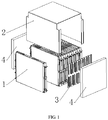
FIG 1 is a schematic structural diagram of a battery module according to this application; -
FIG 2 is a schematic exploded view of a module cell shown inFIG 1 ; and -
FIG 3 is a schematic cross-sectional view of a battery cushion according to this application. -
- 1: Module cell;
- 10: Battery cushion;
- 100: Body;
- 102: Collapsible pores;
- 1020: First pore;
- 1022: Second pore;
- 104: Connected pore;
- 12: Fastening framework;
- 120: Cell accommodation cavity;
- 14: Pouch-type cell;
- 16: Thermally conductive plate;
- 2: Outer metal frame;
- 3: Wire harness separator; and
- 4: End plate.
- The drawings described here are incorporated into the specification as a part of the specification. The drawings illustrate embodiments of this application and are used together with the specification to explain the principles of this application.
- The following describes this application in further detail with reference to specific embodiments and accompanying drawings.
- The words of direction such as "on", "above", "under", "below", "left", and "right" described in the embodiments of this application are described from a perspective shown in the drawings, and shall not be understood as a limitation on the embodiments of this application. In addition, understandably, depending on the context, one element mentioned as being connected "on" or "under" another element not only means that the element may be directly connected "on" or "under" the other element, but also means that the element may be indirectly connected "on" or "under" the other element through an intermediate element.
- As shown in
FIG 1 to FIG. 3 , a battery module disclosed in an embodiment of this application includes at least two (multiple) pouch-type cells 14 and abattery cushion 10. The pouch-type cells 14 are arranged in sequence along a thickness direction of the pouch-type cells. Thebattery cushion 10 is disposed between the pouch-type cells 14, and the pouch-type cells 14 press thebattery cushion 10 tightly so that the pouch-type cells 14 meet a preset pre-tightening force requirement. In a case that the battery module expands during working, thebattery cushion 10 can release a compression space to effectively relieve an expansive force within the battery module. - The battery module may further include an
outer metal frame 2. Theouter metal frame 2 is configured as a U-shaped structure. Each of two sidewalls of theouter metal frame 2 is in contact with two ends that are of the battery module and that are in the thickness direction of the pouch-type cells 14. Therefore, the multiple pouch-type cells 14 and thebattery cushion 10 can press each other tightly to meet the pre-tightening force requirement within the battery module and prevent the battery module from loosening. Anend plate 4 may be disposed at each of the two ends of the U-shaped structure (the two ends along a length direction of the pouch-type cells 14). Theend plate 4 is welded to each of the two ends of the U-shaped structure, and forms, together with the U-shaped structure, a casing of the battery module to protect the battery module on the whole. The multiple pouch-type cells 14 may be electrically connected through a wire harness separator 3. - As shown in
FIG 2 , the battery module disclosed in this application may further include afastening framework 12. Thefastening framework 12, thebattery cushion 10, and the pouch-type cells 14 constitute a module cell, thereby simplifying assembly of the battery module and fastening the pouch-type cells 14 and thebattery cushion 10 more firmly. Thebattery cushion 10 is disposed in thefastening framework 12, and divides thefastening framework 12 into at least twocell accommodation cavities 120 along a thickness direction of the fastening framework. The pouch-type cells 14 are disposed in thecell accommodation cavities 120, and press thebattery cushion 10 tightly. The pouch-type cells 14 on both sides of thebattery cushion 10 can share onebattery cushion 10, thereby reducing the quantity of battery cushions 10, reducing the size of the battery module, and increasing an energy density of the battery module. - Further, the
module cell 1 may further include a thermallyconductive plate 16. The thermallyconductive plate 16 may be a metal plate of high thermal conductivity, such as an aluminum plate. The thermallyconductive plate 16 is disposed on one side of the pouch-type cell 14 away from thebattery cushion 10, so as to reduce a temperature on one side of the pouch-type cell 14 away from thebattery cushion 10 and control the pouch-type cell 14 to expand toward a center location of thefastening framework 12. - As shown in
FIG. 3 , thebattery cushion 10 disclosed in this application includes abody 100 andcollapsible pores 102. Thecollapsible pores 102 are disposed in thebody 100. During assembly of the battery module, thebattery cushion 10 is compressively deformed to meet the pre-tightening force requirement in the battery module. During working of the battery module, the cells expand and thebattery cushion 10 keeps being compressed. Under an extrusion force, thecollapsible pores 102 can be collapsed and release the compression space to effectively relieve the expansive force in the battery module. Thecollapsible pores 102 include at least a first pore 1020 and a second pore 1022. A collapsing pressure of the first pore 1020 is less than a collapsing pressure of the second pore 1022, so that thebattery cushion 10 releases the compression space in a terraced manner according to different extrusion forces. In other words, as thebattery cushion 10 keeps being compressed, the expansive force in the battery module keeps increasing, the first pore 1020 is collapsed first and releases the compression space to reduce the expansive force in the battery module. The second pore 1022 refrains from collapsing so as to maintain the pre-tightening force in the battery module and effectively extend a service life of the battery module. Understandably, thebattery cushion 10 may have a variety ofcollapsible pores 102 that collapse under different collapsing pressures, thereby forming more terraces, releasing the compression space hierarchically, and better adapting to expansive forces in the battery module. - Further, the
collapsible pores 102 may include at least two types of pores that have different diameters. The first pore 1020 has a greater diameter, collapses under a lower collapsing pressure, and provides a larger compression space. In a case of collapsing, the first pore 1020 releases a larger compression space, and effectively reduces the expansive force in the battery module. The second pore 1022 has a smaller diameter, collapses under a higher collapsing pressure, and provides a smaller compression space and a greater reaction force to maintain the pre-tightening force in the battery module after the first pore 1020 is collapsed, thereby meeting both the compression space requirement and the pre-tightening force requirement of the pouch-type cells. - Exemplarily, diameters of the
collapsible pores 102 are 10 µm to 1 mm, so that the collapsible pores are easy to implement and can meet the compression space requirement and the pre-tightening force requirement. Within such a range, the diameters of thecollapsible pores 102 may be reasonably distributed in at least two sections, and two adjacent sections may be continuous or spaced apart from each other. Exemplarily, two adjacent sections are spaced apart from each other (for example, the diameter of the first pore 1020 is 10 µm to 300 µm, and the diameter of the second pore 1022 is 500 µm to 1 mm), so that the collapsing pressure of the first pore 1020 is obviously different from the collapsing pressure of the second pore 1022. - Further, the
collapsible pores 102 may include at least two types of pores whose walls have different lower-limit thicknesses. The wall of the first pore 1020 has a smaller lower-limit thickness and collapses under a lower collapsing pressure. The wall of the second pore 1022 has a greater lower-limit thickness and collapses under a higher collapsing pressure. The thickness of the wall of acollapsible pore 102 is not uniform, and thecollapsible pore 102 generally collapses at a fragile position where the wall is the thinnest. Therefore, terraced collapse can be implemented by configuring different lower-limit thicknesses of the walls of the collapsible pores 102. By controlling the lower-limit thicknesses of the walls of thecollapsible pores 102, the terraced collapse of thecollapsible pores 102 is easier to control and operate. - In a case that the lower-limit thickness of the wall of a
collapsible pore 102 is too small, thecollapsible pore 102 is likely to collapse under the pre-tightening force and fails. In a case that the lower-limit thickness of the wall of thecollapsible pore 102 is too great, thecollapsible pore 102 is not likely to collapse even under a large extrusion force and loses a cushioning effect. Therefore, exemplarily, the lower-limit thickness of the wall of thecollapsible pores 102 according to this embodiment is 1 µm to 0.3 mm. - Further, the
collapsible pores 102 are uniformly distributed in thebody 100, and specifically but without limitation, uniformly distributed in a longitudinal section of the body 100 (the section along a thickness direction of the body 100) and uniformly distributed in a cross section of the body 100 (the section along an extension direction of the body 100). In this way, thebattery cushion 10 has exactly the same compression performance in any direction, thebattery cushion 10 can be uniformly compressed, a reliable contact is achieved between a side of each pouch-type cell 14 and thebattery cushion 10 to prevent tilting, and a good contact of a reaction interface of the cells is ensured. - Specifically, in a case that the
collapsible pores 102 include a first pore 1020 and a second pore 1022, the first pore 1020 and the second pore 1022 are uniformly mixed and uniformly distributed in thebody 100. That is, the first pore 1020 and the second pore 1022 are not hierarchical. This implementation is easy to operate and achieves exactly the same compression performance of thebattery cushion 10 everywhere in a thickness direction of the battery cushion. - Optionally, the first pore 1020 and the second pore 1022 may be disposed hierarchically (along the thickness direction of the battery cushion 10), and the first pore 1020 and the second pore 1022 are uniformly distributed each in a corresponding layer. In this way, the
battery cushion 10 can release the compression space hierarchically, and thebattery cushion 10 can be uniformly compressed. - Exemplarily, a percentage of a volume of the
collapsible pores 102 in a volume of thebody 100 is 40% to 90%, so that thebattery cushion 10 has both high compression performance and resilience. - Specifically, the diameter and the wall thickness of the pores may be controlled by controlling a foaming process, for example, by controlling a foaming temperature, the quantity of a foaming agent, and a foaming time.
- Further, a
connected pore 104 may be disposed in thebody 100. Theconnected pore 104 has a vent and communicates with the outside of thebody 100 through the vent. Theconnected pore 104 does not form a closed space, and therefore, theconnected pore 104 will not collapse under an extrusion force, so that thebattery cushion 10 is always resilient to ensure a reliable pre-tightening force in the battery module. - Further, the
body 100 is made of an elastic insulating material, and thebody 100 is of a flat structure to form a steady contact support for the pouch-type cells 14 and prevent damage to the pouch-type cells 14 or deformation of a surface of the pouch-type cells 14. Specifically, the elastic insulating material may include rubber, silicon foam, polyurethane foam, and the like. - Exemplarily, a thickness of the
body 100 is 0.5 mm to 20 mm. In this way, after the pouch-type cells 14 press thebattery cushion 10 tightly, thebattery cushion 10 can provide a pre-tightening force for the pouch-type cells 14 and still retain a compression space. - An embodiment of this application further discloses a battery cushion forming method, including:
forming collapsible pores in a body by controlling a foaming process, where the collapsible pores include at least a first pore and a second pore, a collapsing pressure of the first pore is less than a collapsing pressure of the second pore, so that the battery cushion can release a compression space in a terraced manner under different extrusion forces. - Optionally, the forming collapsible pores in a body by controlling a foaming process includes:
controlling the foaming process so that the first pore and the second pore are uniformly distributed in a longitudinal section of the body and a cross section of the body. - An embodiment of this application further discloses a battery module forming method, including:
pressing a battery cushion tightly with pouch-type cells, where the battery cushion is formed by using the battery cushion forming method disclosed in any embodiment of this application. - Optionally, the pressing a battery cushion tightly with pouch-type cells includes:
- arranging the pouch-type cells in sequence along a thickness direction of the pouch-type cells; and
- disposing the battery cushion between the pouch-type cells.
- The foregoing descriptions are merely exemplary embodiments of this application, but are not intended to limit this application. A person skilled in the art understands that this application may have various modifications and variations. Any modification, equivalent replacement, improvement, and the like made without departing from the spirit and principles of this application shall fall within the protection scope of this application.
Claims (14)
- A battery cushion, comprising:a body; andcollapsible pores, disposed in the body, wherein the collapsible pores comprise at least a first pore and a second pore, a collapsing pressure of the first pore is less than a collapsing pressure of the second pore, so that the battery cushion can release a compression space in a terraced manner under different extrusion forces.
- The battery cushion according to claim 1, wherein a diameter of the first pore is greater than a diameter of the second pore.
- The battery cushion according to claim 2, wherein a diameter of each collapsible pore is 10 µm to 1 mm.
- The battery cushion according to claim 1, wherein a lower-limit thickness of a wall of the first pore is less than a lower-limit thickness of a wall of the second pore.
- The battery cushion according to claim 4, wherein a thickness of a wall of each collapsible pore is 1 µm to 0.3 mm.
- The battery cushion according to claim 1, wherein the collapsible pores are uniformly distributed in the body, and a percentage of a volume of the collapsible pores in a volume of the body is 40% to 90%.
- The battery cushion according to any one of claims 1 to 6, wherein a connected pore is further disposed in the body, and the connected pore has a vent and communicates with the outside of the body through the vent.
- The battery cushion according to any one of claims 1 to 6, wherein the body is made of an elastic insulating material, and the body is of a flat structure.
- The battery cushion according to any one of claims 1 to 6, wherein a thickness of the body is 0.5 mm to 20 mm.
- A battery module, comprising:at least two pouch-type cells, arranged in sequence along a thickness direction of the pouch-type cells; anda battery cushion, wherein the battery cushion is the battery cushion according to any one of claims 1 to 9, is disposed between the pouch-type cells; andthe pouch-type cells press the battery cushion tightly.
- A battery cushion forming method, comprising:
forming collapsible pores in a body by controlling a foaming process, wherein the collapsible pores comprise at least a first pore and a second pore, a collapsing pressure of the first pore is less than a collapsing pressure of the second pore, so that the battery cushion can release a compression space in a terraced manner under different extrusion forces. - The forming method according to claim 11, wherein the forming collapsible pores in a body by controlling a foaming process comprises:
controlling the foaming process so that the first pore and the second pore are uniformly distributed in a longitudinal section of the body and a cross section of the body. - A battery module forming method, comprising:
pressing a battery cushion tightly with pouch-type cells, wherein the battery cushion is formed by using the battery cushion forming method according to any one of claims 11 to 12. - The forming method according to claim 13, wherein the pressing a battery cushion tightly with pouch-type cells comprises:arranging the pouch-type cells in sequence along a thickness direction of the pouch-type cells; anddisposing the battery cushion between the pouch-type cells.
Priority Applications (1)
| Application Number | Priority Date | Filing Date | Title |
|---|---|---|---|
| EP22197265.6A EP4203155A1 (en) | 2018-10-22 | 2019-10-14 | Battery cushion pad and molding method, and battery module and molding method |
Applications Claiming Priority (2)
| Application Number | Priority Date | Filing Date | Title |
|---|---|---|---|
| CN201821712200.XU CN208674236U (en) | 2018-10-22 | 2018-10-22 | Battery Buffer and Battery Module |
| PCT/CN2019/110917 WO2020083055A1 (en) | 2018-10-22 | 2019-10-14 | Battery cushion pad and molding method, and battery module and molding method |
Related Child Applications (2)
| Application Number | Title | Priority Date | Filing Date |
|---|---|---|---|
| EP22197265.6A Division-Into EP4203155A1 (en) | 2018-10-22 | 2019-10-14 | Battery cushion pad and molding method, and battery module and molding method |
| EP22197265.6A Division EP4203155A1 (en) | 2018-10-22 | 2019-10-14 | Battery cushion pad and molding method, and battery module and molding method |
Publications (3)
| Publication Number | Publication Date |
|---|---|
| EP3799149A1 true EP3799149A1 (en) | 2021-03-31 |
| EP3799149A4 EP3799149A4 (en) | 2021-07-28 |
| EP3799149B1 EP3799149B1 (en) | 2022-11-09 |
Family
ID=65820811
Family Applications (2)
| Application Number | Title | Priority Date | Filing Date |
|---|---|---|---|
| EP19874907.9A Active EP3799149B1 (en) | 2018-10-22 | 2019-10-14 | Battery cushion pad and molding method, and battery module and molding method |
| EP22197265.6A Pending EP4203155A1 (en) | 2018-10-22 | 2019-10-14 | Battery cushion pad and molding method, and battery module and molding method |
Family Applications After (1)
| Application Number | Title | Priority Date | Filing Date |
|---|---|---|---|
| EP22197265.6A Pending EP4203155A1 (en) | 2018-10-22 | 2019-10-14 | Battery cushion pad and molding method, and battery module and molding method |
Country Status (4)
| Country | Link |
|---|---|
| US (1) | US12051818B2 (en) |
| EP (2) | EP3799149B1 (en) |
| CN (1) | CN208674236U (en) |
| WO (1) | WO2020083055A1 (en) |
Cited By (1)
| Publication number | Priority date | Publication date | Assignee | Title |
|---|---|---|---|---|
| EP4037082A3 (en) * | 2020-12-09 | 2022-10-12 | SK Innovation Co., Ltd. | Battery module |
Families Citing this family (7)
| Publication number | Priority date | Publication date | Assignee | Title |
|---|---|---|---|---|
| CN208674236U (en) | 2018-10-22 | 2019-03-29 | 宁德时代新能源科技股份有限公司 | Battery Buffer and Battery Module |
| CN110435269A (en) * | 2019-06-27 | 2019-11-12 | 惠州市保瑞新材料有限公司 | A kind of fire resistant composite material and preparation method |
| KR102938463B1 (en) * | 2020-01-22 | 2026-03-11 | 주식회사 엘지에너지솔루션 | Battery module, battery rack and energy storage system comprising the battery module |
| CN114361702B (en) * | 2020-09-27 | 2023-04-07 | 比亚迪股份有限公司 | Power battery pack and vehicle |
| CN114335846A (en) * | 2020-09-27 | 2022-04-12 | 比亚迪股份有限公司 | Battery tray and battery pack |
| CN113611934A (en) * | 2021-06-24 | 2021-11-05 | 合肥国轩高科动力能源有限公司 | Method for testing battery monomer-module expansion force change relation |
| CN116960429A (en) * | 2022-04-15 | 2023-10-27 | 宁德时代新能源科技股份有限公司 | Battery cells, batteries and electrical equipment |
Family Cites Families (13)
| Publication number | Priority date | Publication date | Assignee | Title |
|---|---|---|---|---|
| US4174014A (en) * | 1975-12-29 | 1979-11-13 | Bjorksten Johan A | Shock absorbent electric vehicle and batteries |
| JP2000247763A (en) * | 1998-12-28 | 2000-09-12 | Kanegafuchi Chem Ind Co Ltd | Inorganic hydraulic composition, method for producing inorganic lightweight molded article, and inorganic lightweight molded article |
| US20040119185A1 (en) * | 2002-12-23 | 2004-06-24 | Chen Ching Hsi | Method for manufacturing opened-cell plastic foams |
| WO2007097249A1 (en) * | 2006-02-20 | 2007-08-30 | Daicel Chemical Industries, Ltd. | Porous film and layered product including porous film |
| EP2579364A4 (en) * | 2010-05-31 | 2016-03-23 | Sumitomo Electric Industries | THREE-DIMENSIONAL THREE-LIKE POROUS ALUMINUM MATERIAL, ELECTRODE COMPRISING POROUS ALUMINUM MATERIAL, NONAQUEOUS ELECTROLYTE BATTERY EQUIPPED WITH ELECTRODE AND NONAQUEOUS ELECTROLYTIC SOLUTION CAPACITOR EQUIPPED WITH THE ELECTRODE |
| US9799870B2 (en) | 2012-03-30 | 2017-10-24 | Toray Industries, Inc. | Multilayered microporous polyolefin film |
| US9287536B2 (en) | 2012-08-07 | 2016-03-15 | John E. Waters | Battery module construction |
| KR101331027B1 (en) * | 2013-04-19 | 2013-11-19 | 주식회사 셀모티브 | Manufacturing method of metal foam with uniformly distributed nano-sized pores and metal foam manufactured thereby |
| EP3118910B1 (en) * | 2015-07-15 | 2022-03-30 | Carl Freudenberg KG | Holding element for pouch cells |
| CN204936807U (en) * | 2015-08-18 | 2016-01-06 | 北京汽车股份有限公司 | Automotive oil tank operator guards and automobile |
| CN206541873U (en) * | 2017-03-21 | 2017-10-03 | 宁德时代新能源科技股份有限公司 | Battery modules |
| CN207572431U (en) * | 2017-12-06 | 2018-07-03 | 威睿电动汽车技术(苏州)有限公司 | A kind of modular structure of battery pack, battery pack and vehicle |
| CN208674236U (en) * | 2018-10-22 | 2019-03-29 | 宁德时代新能源科技股份有限公司 | Battery Buffer and Battery Module |
-
2018
- 2018-10-22 CN CN201821712200.XU patent/CN208674236U/en active Active
-
2019
- 2019-10-14 EP EP19874907.9A patent/EP3799149B1/en active Active
- 2019-10-14 EP EP22197265.6A patent/EP4203155A1/en active Pending
- 2019-10-14 WO PCT/CN2019/110917 patent/WO2020083055A1/en not_active Ceased
-
2020
- 2020-12-31 US US17/139,811 patent/US12051818B2/en active Active
Cited By (1)
| Publication number | Priority date | Publication date | Assignee | Title |
|---|---|---|---|---|
| EP4037082A3 (en) * | 2020-12-09 | 2022-10-12 | SK Innovation Co., Ltd. | Battery module |
Also Published As
| Publication number | Publication date |
|---|---|
| US12051818B2 (en) | 2024-07-30 |
| EP3799149B1 (en) | 2022-11-09 |
| WO2020083055A1 (en) | 2020-04-30 |
| EP4203155A1 (en) | 2023-06-28 |
| US20210126317A1 (en) | 2021-04-29 |
| CN208674236U (en) | 2019-03-29 |
| EP3799149A4 (en) | 2021-07-28 |
Similar Documents
| Publication | Publication Date | Title |
|---|---|---|
| EP3799149B1 (en) | Battery cushion pad and molding method, and battery module and molding method | |
| CN108138885B (en) | Hollow unit with outwardly curved surface | |
| US20170237112A1 (en) | Porous spacers for electrochemical cells | |
| KR20170009741A (en) | Receiving element for pouch-cells | |
| CN109075275A (en) | Electric core group with buffer part | |
| KR102873734B1 (en) | Energy storage system | |
| JP7165760B2 (en) | Buffer rubber and its reaction force adjustment method and pedestal | |
| CN118017117A (en) | Hybrid compression pad for battery cell stack and method for manufacturing same, and battery cell module | |
| EP4318740B1 (en) | Battery cell, battery, electrical device, and battery cell manufacturing method | |
| CN113381099A (en) | Battery case, battery pack, battery module and electric vehicle | |
| JP2022059783A (en) | Composite insulation and its manufacturing method | |
| US11469442B2 (en) | Energy storage device | |
| CN115799706A (en) | Battery module | |
| CN118431640A (en) | Battery module and method of manufacturing the same | |
| KR102659474B1 (en) | Battery module having heat dissipation and insulation function and battery pack having the same | |
| KR20240120666A (en) | Battery pack | |
| CN222190932U (en) | Thermal insulation structure, power battery and vehicle | |
| KR20170050875A (en) | Secondary battery | |
| JP7112377B2 (en) | Battery | |
| JP2022533581A (en) | CYLINDRICAL BATTERY PRESS SYSTEM AND CYLINDRICAL BATTERY CELL COMPRESSION METHOD | |
| CN114335846A (en) | Battery tray and battery pack | |
| CN222126719U (en) | A battery module | |
| US20250239709A1 (en) | Insert element for a battery module, and battery module | |
| CN221486631U (en) | Battery cells, batteries and electrical devices | |
| JP2025119609A (en) | Energy Storage Unit |
Legal Events
| Date | Code | Title | Description |
|---|---|---|---|
| STAA | Information on the status of an ep patent application or granted ep patent |
Free format text: STATUS: THE INTERNATIONAL PUBLICATION HAS BEEN MADE |
|
| PUAI | Public reference made under article 153(3) epc to a published international application that has entered the european phase |
Free format text: ORIGINAL CODE: 0009012 |
|
| STAA | Information on the status of an ep patent application or granted ep patent |
Free format text: STATUS: REQUEST FOR EXAMINATION WAS MADE |
|
| 17P | Request for examination filed |
Effective date: 20201223 |
|
| AK | Designated contracting states |
Kind code of ref document: A1 Designated state(s): AL AT BE BG CH CY CZ DE DK EE ES FI FR GB GR HR HU IE IS IT LI LT LU LV MC MK MT NL NO PL PT RO RS SE SI SK SM TR |
|
| AX | Request for extension of the european patent |
Extension state: BA ME |
|
| A4 | Supplementary search report drawn up and despatched |
Effective date: 20210630 |
|
| RIC1 | Information provided on ipc code assigned before grant |
Ipc: H01M 50/211 20210101AFI20210624BHEP Ipc: H01M 50/242 20210101ALI20210624BHEP |
|
| DAV | Request for validation of the european patent (deleted) | ||
| DAX | Request for extension of the european patent (deleted) | ||
| REG | Reference to a national code |
Ref country code: DE Ref legal event code: R079 Ref document number: 602019021842 Country of ref document: DE Free format text: PREVIOUS MAIN CLASS: H01M0002100000 Ipc: H01M0050211000 |
|
| GRAP | Despatch of communication of intention to grant a patent |
Free format text: ORIGINAL CODE: EPIDOSNIGR1 |
|
| STAA | Information on the status of an ep patent application or granted ep patent |
Free format text: STATUS: GRANT OF PATENT IS INTENDED |
|
| RIC1 | Information provided on ipc code assigned before grant |
Ipc: H01M 50/291 20210101ALI20220715BHEP Ipc: H01M 50/242 20210101ALI20220715BHEP Ipc: H01M 50/211 20210101AFI20220715BHEP |
|
| INTG | Intention to grant announced |
Effective date: 20220803 |
|
| GRAS | Grant fee paid |
Free format text: ORIGINAL CODE: EPIDOSNIGR3 |
|
| GRAA | (expected) grant |
Free format text: ORIGINAL CODE: 0009210 |
|
| STAA | Information on the status of an ep patent application or granted ep patent |
Free format text: STATUS: THE PATENT HAS BEEN GRANTED |
|
| AK | Designated contracting states |
Kind code of ref document: B1 Designated state(s): AL AT BE BG CH CY CZ DE DK EE ES FI FR GB GR HR HU IE IS IT LI LT LU LV MC MK MT NL NO PL PT RO RS SE SI SK SM TR |
|
| REG | Reference to a national code |
Ref country code: GB Ref legal event code: FG4D |
|
| REG | Reference to a national code |
Ref country code: CH Ref legal event code: EP Ref country code: AT Ref legal event code: REF Ref document number: 1530960 Country of ref document: AT Kind code of ref document: T Effective date: 20221115 |
|
| REG | Reference to a national code |
Ref country code: DE Ref legal event code: R096 Ref document number: 602019021842 Country of ref document: DE |
|
| REG | Reference to a national code |
Ref country code: IE Ref legal event code: FG4D |
|
| REG | Reference to a national code |
Ref country code: LT Ref legal event code: MG9D |
|
| REG | Reference to a national code |
Ref country code: NL Ref legal event code: MP Effective date: 20221109 |
|
| REG | Reference to a national code |
Ref country code: AT Ref legal event code: MK05 Ref document number: 1530960 Country of ref document: AT Kind code of ref document: T Effective date: 20221109 |
|
| PG25 | Lapsed in a contracting state [announced via postgrant information from national office to epo] |
Ref country code: SE Free format text: LAPSE BECAUSE OF FAILURE TO SUBMIT A TRANSLATION OF THE DESCRIPTION OR TO PAY THE FEE WITHIN THE PRESCRIBED TIME-LIMIT Effective date: 20221109 Ref country code: PT Free format text: LAPSE BECAUSE OF FAILURE TO SUBMIT A TRANSLATION OF THE DESCRIPTION OR TO PAY THE FEE WITHIN THE PRESCRIBED TIME-LIMIT Effective date: 20230309 Ref country code: NO Free format text: LAPSE BECAUSE OF FAILURE TO SUBMIT A TRANSLATION OF THE DESCRIPTION OR TO PAY THE FEE WITHIN THE PRESCRIBED TIME-LIMIT Effective date: 20230209 Ref country code: LT Free format text: LAPSE BECAUSE OF FAILURE TO SUBMIT A TRANSLATION OF THE DESCRIPTION OR TO PAY THE FEE WITHIN THE PRESCRIBED TIME-LIMIT Effective date: 20221109 Ref country code: FI Free format text: LAPSE BECAUSE OF FAILURE TO SUBMIT A TRANSLATION OF THE DESCRIPTION OR TO PAY THE FEE WITHIN THE PRESCRIBED TIME-LIMIT Effective date: 20221109 Ref country code: ES Free format text: LAPSE BECAUSE OF FAILURE TO SUBMIT A TRANSLATION OF THE DESCRIPTION OR TO PAY THE FEE WITHIN THE PRESCRIBED TIME-LIMIT Effective date: 20221109 Ref country code: AT Free format text: LAPSE BECAUSE OF FAILURE TO SUBMIT A TRANSLATION OF THE DESCRIPTION OR TO PAY THE FEE WITHIN THE PRESCRIBED TIME-LIMIT Effective date: 20221109 |
|
| PG25 | Lapsed in a contracting state [announced via postgrant information from national office to epo] |
Ref country code: RS Free format text: LAPSE BECAUSE OF FAILURE TO SUBMIT A TRANSLATION OF THE DESCRIPTION OR TO PAY THE FEE WITHIN THE PRESCRIBED TIME-LIMIT Effective date: 20221109 Ref country code: PL Free format text: LAPSE BECAUSE OF FAILURE TO SUBMIT A TRANSLATION OF THE DESCRIPTION OR TO PAY THE FEE WITHIN THE PRESCRIBED TIME-LIMIT Effective date: 20221109 Ref country code: LV Free format text: LAPSE BECAUSE OF FAILURE TO SUBMIT A TRANSLATION OF THE DESCRIPTION OR TO PAY THE FEE WITHIN THE PRESCRIBED TIME-LIMIT Effective date: 20221109 Ref country code: IS Free format text: LAPSE BECAUSE OF FAILURE TO SUBMIT A TRANSLATION OF THE DESCRIPTION OR TO PAY THE FEE WITHIN THE PRESCRIBED TIME-LIMIT Effective date: 20230309 Ref country code: HR Free format text: LAPSE BECAUSE OF FAILURE TO SUBMIT A TRANSLATION OF THE DESCRIPTION OR TO PAY THE FEE WITHIN THE PRESCRIBED TIME-LIMIT Effective date: 20221109 Ref country code: GR Free format text: LAPSE BECAUSE OF FAILURE TO SUBMIT A TRANSLATION OF THE DESCRIPTION OR TO PAY THE FEE WITHIN THE PRESCRIBED TIME-LIMIT Effective date: 20230210 |
|
| P01 | Opt-out of the competence of the unified patent court (upc) registered |
Effective date: 20230516 |
|
| PG25 | Lapsed in a contracting state [announced via postgrant information from national office to epo] |
Ref country code: NL Free format text: LAPSE BECAUSE OF FAILURE TO SUBMIT A TRANSLATION OF THE DESCRIPTION OR TO PAY THE FEE WITHIN THE PRESCRIBED TIME-LIMIT Effective date: 20221109 |
|
| PG25 | Lapsed in a contracting state [announced via postgrant information from national office to epo] |
Ref country code: SM Free format text: LAPSE BECAUSE OF FAILURE TO SUBMIT A TRANSLATION OF THE DESCRIPTION OR TO PAY THE FEE WITHIN THE PRESCRIBED TIME-LIMIT Effective date: 20221109 Ref country code: RO Free format text: LAPSE BECAUSE OF FAILURE TO SUBMIT A TRANSLATION OF THE DESCRIPTION OR TO PAY THE FEE WITHIN THE PRESCRIBED TIME-LIMIT Effective date: 20221109 Ref country code: EE Free format text: LAPSE BECAUSE OF FAILURE TO SUBMIT A TRANSLATION OF THE DESCRIPTION OR TO PAY THE FEE WITHIN THE PRESCRIBED TIME-LIMIT Effective date: 20221109 Ref country code: DK Free format text: LAPSE BECAUSE OF FAILURE TO SUBMIT A TRANSLATION OF THE DESCRIPTION OR TO PAY THE FEE WITHIN THE PRESCRIBED TIME-LIMIT Effective date: 20221109 Ref country code: CZ Free format text: LAPSE BECAUSE OF FAILURE TO SUBMIT A TRANSLATION OF THE DESCRIPTION OR TO PAY THE FEE WITHIN THE PRESCRIBED TIME-LIMIT Effective date: 20221109 |
|
| REG | Reference to a national code |
Ref country code: DE Ref legal event code: R097 Ref document number: 602019021842 Country of ref document: DE |
|
| PG25 | Lapsed in a contracting state [announced via postgrant information from national office to epo] |
Ref country code: SK Free format text: LAPSE BECAUSE OF FAILURE TO SUBMIT A TRANSLATION OF THE DESCRIPTION OR TO PAY THE FEE WITHIN THE PRESCRIBED TIME-LIMIT Effective date: 20221109 Ref country code: AL Free format text: LAPSE BECAUSE OF FAILURE TO SUBMIT A TRANSLATION OF THE DESCRIPTION OR TO PAY THE FEE WITHIN THE PRESCRIBED TIME-LIMIT Effective date: 20221109 |
|
| PLBE | No opposition filed within time limit |
Free format text: ORIGINAL CODE: 0009261 |
|
| STAA | Information on the status of an ep patent application or granted ep patent |
Free format text: STATUS: NO OPPOSITION FILED WITHIN TIME LIMIT |
|
| 26N | No opposition filed |
Effective date: 20230810 |
|
| PG25 | Lapsed in a contracting state [announced via postgrant information from national office to epo] |
Ref country code: SI Free format text: LAPSE BECAUSE OF FAILURE TO SUBMIT A TRANSLATION OF THE DESCRIPTION OR TO PAY THE FEE WITHIN THE PRESCRIBED TIME-LIMIT Effective date: 20221109 |
|
| PG25 | Lapsed in a contracting state [announced via postgrant information from national office to epo] |
Ref country code: MC Free format text: LAPSE BECAUSE OF FAILURE TO SUBMIT A TRANSLATION OF THE DESCRIPTION OR TO PAY THE FEE WITHIN THE PRESCRIBED TIME-LIMIT Effective date: 20221109 |
|
| REG | Reference to a national code |
Ref country code: CH Ref legal event code: PL |
|
| REG | Reference to a national code |
Ref country code: BE Ref legal event code: MM Effective date: 20231031 |
|
| PG25 | Lapsed in a contracting state [announced via postgrant information from national office to epo] |
Ref country code: LU Free format text: LAPSE BECAUSE OF NON-PAYMENT OF DUE FEES Effective date: 20231014 |
|
| PG25 | Lapsed in a contracting state [announced via postgrant information from national office to epo] |
Ref country code: LU Free format text: LAPSE BECAUSE OF NON-PAYMENT OF DUE FEES Effective date: 20231014 |
|
| PG25 | Lapsed in a contracting state [announced via postgrant information from national office to epo] |
Ref country code: CH Free format text: LAPSE BECAUSE OF NON-PAYMENT OF DUE FEES Effective date: 20231031 |
|
| PG25 | Lapsed in a contracting state [announced via postgrant information from national office to epo] |
Ref country code: CH Free format text: LAPSE BECAUSE OF NON-PAYMENT OF DUE FEES Effective date: 20231031 |
|
| REG | Reference to a national code |
Ref country code: DE Ref legal event code: R081 Ref document number: 602019021842 Country of ref document: DE Owner name: CONTEMPORARY AMPEREX TECHNOLOGY (HONG KONG) LI, HK Free format text: FORMER OWNER: CONTEMPORARY AMPEREX TECHNOLOGY CO., LIMITED, NINGDE, FUJIAN, CN |
|
| PG25 | Lapsed in a contracting state [announced via postgrant information from national office to epo] |
Ref country code: BE Free format text: LAPSE BECAUSE OF NON-PAYMENT OF DUE FEES Effective date: 20231031 |
|
| REG | Reference to a national code |
Ref country code: GB Ref legal event code: 732E Free format text: REGISTERED BETWEEN 20240822 AND 20240828 |
|
| PG25 | Lapsed in a contracting state [announced via postgrant information from national office to epo] |
Ref country code: IE Free format text: LAPSE BECAUSE OF NON-PAYMENT OF DUE FEES Effective date: 20231014 |
|
| PG25 | Lapsed in a contracting state [announced via postgrant information from national office to epo] |
Ref country code: IE Free format text: LAPSE BECAUSE OF NON-PAYMENT OF DUE FEES Effective date: 20231014 |
|
| PG25 | Lapsed in a contracting state [announced via postgrant information from national office to epo] |
Ref country code: BG Free format text: LAPSE BECAUSE OF FAILURE TO SUBMIT A TRANSLATION OF THE DESCRIPTION OR TO PAY THE FEE WITHIN THE PRESCRIBED TIME-LIMIT Effective date: 20221109 |
|
| PG25 | Lapsed in a contracting state [announced via postgrant information from national office to epo] |
Ref country code: BG Free format text: LAPSE BECAUSE OF FAILURE TO SUBMIT A TRANSLATION OF THE DESCRIPTION OR TO PAY THE FEE WITHIN THE PRESCRIBED TIME-LIMIT Effective date: 20221109 |
|
| PG25 | Lapsed in a contracting state [announced via postgrant information from national office to epo] |
Ref country code: CY Free format text: LAPSE BECAUSE OF FAILURE TO SUBMIT A TRANSLATION OF THE DESCRIPTION OR TO PAY THE FEE WITHIN THE PRESCRIBED TIME-LIMIT; INVALID AB INITIO Effective date: 20191014 |
|
| PG25 | Lapsed in a contracting state [announced via postgrant information from national office to epo] |
Ref country code: HU Free format text: LAPSE BECAUSE OF FAILURE TO SUBMIT A TRANSLATION OF THE DESCRIPTION OR TO PAY THE FEE WITHIN THE PRESCRIBED TIME-LIMIT; INVALID AB INITIO Effective date: 20191014 |
|
| PGFP | Annual fee paid to national office [announced via postgrant information from national office to epo] |
Ref country code: IT Payment date: 20250922 Year of fee payment: 7 |
|
| PGFP | Annual fee paid to national office [announced via postgrant information from national office to epo] |
Ref country code: GB Payment date: 20250821 Year of fee payment: 7 |
|
| PGFP | Annual fee paid to national office [announced via postgrant information from national office to epo] |
Ref country code: FR Payment date: 20250808 Year of fee payment: 7 |
|
| PG25 | Lapsed in a contracting state [announced via postgrant information from national office to epo] |
Ref country code: TR Free format text: LAPSE BECAUSE OF FAILURE TO SUBMIT A TRANSLATION OF THE DESCRIPTION OR TO PAY THE FEE WITHIN THE PRESCRIBED TIME-LIMIT Effective date: 20221109 |
|
| PGFP | Annual fee paid to national office [announced via postgrant information from national office to epo] |
Ref country code: DE Payment date: 20250819 Year of fee payment: 7 |