EP3799086A1 - Permanent magnet based magnetiser - Google Patents
Permanent magnet based magnetiser Download PDFInfo
- Publication number
- EP3799086A1 EP3799086A1 EP19199709.7A EP19199709A EP3799086A1 EP 3799086 A1 EP3799086 A1 EP 3799086A1 EP 19199709 A EP19199709 A EP 19199709A EP 3799086 A1 EP3799086 A1 EP 3799086A1
- Authority
- EP
- European Patent Office
- Prior art keywords
- passage
- magnetiser
- housing
- permanent magnet
- opposing surfaces
- Prior art date
- Legal status (The legal status is an assumption and is not a legal conclusion. Google has not performed a legal analysis and makes no representation as to the accuracy of the status listed.)
- Granted
Links
Images



Classifications
-
- H—ELECTRICITY
- H01—ELECTRIC ELEMENTS
- H01F—MAGNETS; INDUCTANCES; TRANSFORMERS; SELECTION OF MATERIALS FOR THEIR MAGNETIC PROPERTIES
- H01F7/00—Magnets
- H01F7/02—Permanent magnets [PM]
- H01F7/0273—Magnetic circuits with PM for magnetic field generation
- H01F7/0278—Magnetic circuits with PM for magnetic field generation for generating uniform fields, focusing, deflecting electrically charged particles
-
- H—ELECTRICITY
- H01—ELECTRIC ELEMENTS
- H01F—MAGNETS; INDUCTANCES; TRANSFORMERS; SELECTION OF MATERIALS FOR THEIR MAGNETIC PROPERTIES
- H01F7/00—Magnets
- H01F7/02—Permanent magnets [PM]
- H01F7/0273—Magnetic circuits with PM for magnetic field generation
-
- H—ELECTRICITY
- H01—ELECTRIC ELEMENTS
- H01F—MAGNETS; INDUCTANCES; TRANSFORMERS; SELECTION OF MATERIALS FOR THEIR MAGNETIC PROPERTIES
- H01F13/00—Apparatus or processes for magnetising or demagnetising
- H01F13/003—Methods and devices for magnetising permanent magnets
-
- H—ELECTRICITY
- H01—ELECTRIC ELEMENTS
- H01F—MAGNETS; INDUCTANCES; TRANSFORMERS; SELECTION OF MATERIALS FOR THEIR MAGNETIC PROPERTIES
- H01F7/00—Magnets
- H01F7/02—Permanent magnets [PM]
- H01F7/0205—Magnetic circuits with PM in general
- H01F7/021—Construction of PM
Definitions
- the current invention relates to a magnetiser comprising a housing, a passage arranged inside the housing, and a permanent magnet assembly arranged outside the passage to provide a magnetic field passing through the passage, said housing comprising an inlet to the passage and an outlet from the passage such that an object to be magnetised can be inserted into the passage via the inlet and removed via the outlet.
- a magnetiser as described above is used to magnetise magnetisable objects.
- One simple example of the use of such a magnetiser is to magnetise the tip of a screwdriver.
- the magnetiser is a simple device having a housing with an opening into a passage and a permanent magnet arranged to provide a magnetic field through the passage.
- a user then inserts the screwdriver tip into the opening to place the screwdriver tip inside the passage.
- the magnetic field in the magnetiser then magnetises the screwdriver tip.
- the screwdriver tip is removed from the passage.
- the inlet and the outlet are the same as the screw driver is inserted into and removed from the passage via the same opening in the housing.
- magnetisers While the above description illustrates one simple use of a magnetiser, there are many different applications of magnetisers. In the case of a screwdriver, the actual magnetic properties of the screwdriver are not so important. However, in other applications, for example in a situation where a magnetic component is a component in a position sensor assembly, it is necessary to magnetise the object very precisely. In this case, the magnetic field of the magnetiser has to be very precise. It is well known that permanent magnet based magnetisers as mentioned in the opening paragraph are not very precise and there are many undesired magnetic effects which can affect the magnetic field in the magnetised object.
- the object to be magnetised can be first inserted into a passage in the electric magnet based magnetiser while the electric current is not applied. Electric current is first supplied to the coil of the electric magnet to create the magnetic field after the object to be magnetised has been inserted in the passage. When the element to be magnetised is properly magnetised, the current is stopped and the field is removed. Then the object can be removed from the passage of the magnetiser. In this way, any undesired magnetic fields around the entrance and exit of the magnetiser can be avoided and the object is magnetised with a very precise magnetic field.
- a magnetiser as mentioned in the opening paragraph, where the passage comprises a uniform portion where opposing surfaces of the permanent magnet assembly are arranged a uniform distance apart along the length of the uniform portion and a diverging portion arranged between one end of the uniform portion of the passage and the outlet of the housing where opposing surfaces of the permanent magnet assembly diverge such that the distance between opposing surfaces of the diverging portion nearest the uniform portion is less than the distance between opposing surfaces of the diverging portion nearest the outlet and where the average angle of the normal vector of the opposing surfaces of the diverging portion to a longitudinal centre axis of the passage is greater than 45 degrees.
- opposing surfaces should be understood as surfaces, or portions of surfaces, which are arranged on opposite sides of a plane passing through the longitudinal centre axis of the passage.
- the opposing surfaces are the two opposing walls.
- the opposing surfaces should be interpreted as opposing portions of the inner cylindrical surface of the passage.
- the average angle of the normal vector of the opposing surfaces of the diverging portion to the longitudinal centre axis of the passage is greater than 55 degrees or greater than 65 degrees.
- the passage can be arranged such that the uniform portion transitions smoothly into the diverging portion.
- the average tangent vector to the surface of the diverging portion on a plane passing through the longitudinal centre axis of the passage is less than 45 degrees, less than 35 degrees or less than 25 degrees.
- the distance between opposing surfaces of the diverging portion nearest to the uniform portion is the same as the distance between opposing surfaces of the uniform portion of the passage.
- the magnetic field lines generated by the permanent magnet assembly at the longitudinal centre of the uniform portion are essentially perpendicular to the longitudinal centre axis of the passage.
- the permanent magnet assembly comprises a permanent magnet arranged outside the passage and an insert arranged between the permanent magnet and the passage, said insert being made of a material having a relative magnetic permeability greater than 1.
- the length of the permanent magnet along the longitudinal axis of the passage is the same or greater than the length of the insert along the longitudinal axis of the passage.
- the magnetic field lines generated by the permanent magnet are conducted to the passage via the insert.
- the distance D4 between opposing surfaces of the diverging portion nearest the outlet is at least 1.2 times greater than the distance D3 between the opposing surfaces of the uniform portion. In one embodiment, the distance D4 is at least 1.3 times greater, at least 1.4 times greater, at least 1.5 times greater or at least 1.7 times greater than D3.
- the length D1 of the uniform portion is at least 10mm. In one embodiment, the distance D3 is at least 5mm, at least 6mm, at least 7mm or at least 8mm. In one embodiment, the dimension D1 is greater than D3. In one embodiment, the dimension D5 is at least twice, at least three times or at least four times greater than D3.
- the length D2 of the diverging portion in a direction parallel to the longitudinal centre axis of the passage is greater than 0,5 times the distance D3 between the opposing surfaces of the uniform portion. In one embodiment, the length D2 is 0.6 times, 0.7 times, 0.8 times or 0.9 times greater than D3.
- the inlet and the outlet in the housing are the same opening, such that the object to be magnetised is introduced into and removed from the passage via the same opening in the housing.
- the inlet and the outlet in the housing are two different openings in the housing such that the object to be magnetised enters the passage via the inlet and leaves the passage via the outlet.
- the permanent magnet assembly comprises a circular array of magnets arranged around the periphery of the passage. In one embodiment, the permanent magnet assembly comprises an array of magnets arranged as a Halbach array. In one embodiment, the Halbach array is arranged as a circular Halbach array where the individual magnets of the Halbach array are arranged to provide a multi pole magnetic field passing through the uniform portion essentially perpendicular to the longitudinal centre axis of the passage.
- a magnetiser according to any one of claims 1 to 8, characterized in that the permanent magnet assembly is arranged to provide at least a two-pole magnetic field in the uniform portion of the passage. In one embodiment, the permanent magnet assembly is arranged to provide at least a four-pole, at least a six-pole, or at least an eight-pole magnetic field in the uniform portion of the passage.
- the invention also relates to a magnetising mechanism comprising a magnetiser as described herein and an actuator, said actuator being arranged to repeatedly move the magnetiser from a first position to a second position, said first position being arranged such that the passage is located away from an object to be magnetised and said second position being arranged such that the uniform portion of the passage of the magnetiser is arranged around the object to be magnetised.
- a magnetising mechanism comprising a magnetiser according to any one of claims 1 to 9 and an actuator, said actuator being arranged to grip an object to be magnetised, move the object into the uniform portion of the passage in the magnetiser, remove the object from the passage in the magnetiser and release the object.
- Figures 1 to 6 shows different views and charts related to a first embodiment 1 of a permanent magnet based magnetiser according to the current invention.
- the magnetiser 1 comprises a circular array 2 of shaped permanent magnets 4.
- Each of said permanent magnets having a roughly pie shaped cross section, which when arranged in a circular array form a Halbach array.
- the magnetizations of the individual magnets is shown in figure 3 and a partial view of the resulting magnetic field of the overall assembly is shown in figure 4 .
- the resulting assembly provides a magnetiser having a magnetic field with four poles.
- the resulting magnetic field and the number of poles can be changed.
- the magnetiser has an outer body made of permanent magnets 4 and a passage 8 passing through the magnets.
- the passage 8 has a longitudinal centre axis L.
- the passage has an upper opening 10 and a lower opening 12.
- the function of the openings can be different depending on how the magnetiser is used.
- an object to be magnetised is typically inserted into the upper opening 10 and removed again from the upper opening 10.
- the upper opening 10 functions as both an inlet into and an outlet from the passage.
- an object is inserted into the passage via the lower opening 12 and removed from the passage via the upper opening 10.
- the passage 8 in the current embodiment comprises two portions: a uniform portion 14 and a diverging portion 16.
- the magnets 4 are shaped such that the opposing surfaces of the magnets are arranged parallel to each other such that the distance between the opposing surfaces of the uniform portion are constant along the length D1 of the uniform portion.
- the magnetiser since the magnetiser is arranged as a circular array of magnets, it should be understood that the opposing surfaces as discussed here are all part of the same cylindrical surface, however for the sake of this specification, opposing portions of the cylindrical surface should be understood as opposing surfaces.
- the magnets 4 are shaped to form a diverging portion 16.
- the diverging portion is arranged so that as the object leaves the passageway via the outlet, the opposing surfaces 16 of the magnets diverge away from each other.
- Different dimensions are shown on figure 2 to better describe the dimensions of the magnetiser.
- the length of the uniform portion along the longitudinal centre axis is shown by the dimension D1.
- the length of the diverging portion along a distance parallel to the longitudinal centre axis of the passage is shown by D2.
- the distance between the opposing surfaces of the uniform portion is shown by D3 and the maximum distance between the opposing surfaces of the diverging portion is shown by D4.
- the outer diameter of the circular array of magnets is shown by D5.
- the angle that the tangent vector to the opposing surfaces of the diverging portion makes to the longitudinal axis is shown by the angle A.
- the normal vector to the surface in the diverging portion is shown by the vector N.
- the angle of the normal vector to the longitudinal axis is 90 degrees minus the angle A.
- D1 is 31,2mm
- D2 is 8,8mm
- D3 is 10mm
- D4 is 15,84mm
- D5 is 44mm
- the angle A is 20 degrees (or the angle of the normal vector to the longitudinal centre axis is 70 degrees).
- the magnetiser 1 is arranged with a housing (not shown) arranged around the permanent magnets 4 to hold the magnets in place and protect them from damage.
- the housing is made from aluminium.
- the housing could be made from soft-magnetic material or non-magnetic material.
- Figure 5 shows the properties of the magnetic field inside the uniform portion of the passage 8.
- the figure shows the radial (Brad) and tangential (Btan) component of the magnetic flux at different angular positions travelling around the circumference of the passageway at a distance of 2.5mm from the central axis of the passage. This is shown by the dashed circle comprising the point A as shown in figures 3 and 4 .
- the magnetic field has a very sinusoidal property which provides for a nice magnetic field in the magnetised object.
- Figure 6 shows the different components of the magnetic field at different longitudinal positions along the longitudinal axis of the passage.
- the first path is a longitudinal line offset 2.5mm from the longitudinal centre axis (point A in figures 3 and 4 ) and the second path is a longitudinal line offset 3.7mm (point B in figures 3 and 4 ) from the longitudinal centre axis.
- the Z-coordinate shown on the x-axis in the figure is the position along the longitudinal centre axis.
- the position 0mm is right in the middle of the passage.
- the positions -40 and +40 are located outside the passage.
- the Radial components (Brad) in the centre of the passage are very uniform and the z components (Bz) are very small. However, near the inlet and the outlet, the z-components of the magnetic field get quite large.
- the field is shown at the lower opening 12 of the passage and to the right in the figure (from around 10 to 30), the field is shown at the upper opening 10.
- the z-component effects at the upper opening 10 are much reduced when compared to the z-component effects at the lower opening 12.
- the z-component effect is less than 0.2 T at 3.7mm from the centre while the z-component effect at the lower opening is around 0.4T. This means that the Z component effect is reduced by at least half by providing the diverging portion at the outlet of the passage.
- Figure 7 shows an embodiment 30, where a sleeve 32 has been provided to protect the magnet from damage.
- An extra angled portion 34 has been provided at the upper portion of the diverging portion. This extra angled portion allows a good seat of the sleeve.
- the average angle of the diverging portion is greater than in the embodiment of figures 1 to 6 , however one can see that the first portion is around 20 degrees and the second portion is around 40 degrees. However, the change between uniform portion is 20 degrees and then a further change of 20 degrees is made. Hence the average rate of change of the angle of the diverging surface is not so large.
- the sleeve is made from stainless steel so that the magnetic properties of the magnets are not affected so much. Other materials could also be used for the sleeve .
- the sleeve is made from a magnetically permeable material. This embodiment is constructed from a magnet assembly similar to the embodiment shown in figures 1-6 .
- Figure 8 shows another embodiment 36 similar to the embodiment of figures 1 to 6 , but where instead of a diverging portion with a linear diverging surface, in this case, the diverging surface is a curved surface 38.
- the rate of change of the tangent angle along the surface is around 2 degrees per mm.
- the average rate of change of the diverging surface could be less than 4 degrees per mm, less than 3 degrees per mm or less than 2 degrees per mm.
- Figure 9 shows another embodiment 40 similar to the embodiment of figures 1 to 6 but where instead of one linear diverging surface, the diverging surface comprises three individual portions 42, 44, 46 having different angles.
- the first diverging portion closest to the uniform portion has an angle of approximately 11 degrees
- the second portion has an angle of approximately 29 degrees
- the last portion closest to the outlet has an angle of approximately 62 degrees.
- Figure 10 shows an example embodiment 50 of a di-pole magnetiser.
- two permanent magnets 52, 54 are arranged on either side of a passage 56.
- a first and second magnetic conducting plate 58, 60 are arranged on either side of the magnets.
- the upper portion 62, 64 of the conducing plates are provided with a curved entrance 66 and exit 68 and a uniform central portion 70.
- a passage 56 is arranged between the curved surfaces. An object can be introduced into the passage at one end and moved through the passage to the other end to magnetize the object.
- the passage 56 has two opposing parallel surfaces 66 and is open at the top and closed at the bottom.
- the magnetic field is arranged to pass essentially perpendicular through the passage from one opposing surface to the other at the central portion (uniform portion) 66 of the passage 56.
- Each end of the passage is formed as a diverging surface.
- Figure 12 shows another embodiment 80, where a number of permanent magnets 82 are lined with a protective lining 84.
- the magnets however still have the uniform portion 86 defining the passage with parallel side walls and a diverging portion 88 with diverging opposing surfaces.
- the magnets are in this case arranged as a circular array as in the embodiment of figures 1 to 6 .
- the magnets 82 and the protective lining 84 form a permanent magnetic assembly.
- Figure 13 shows another embodiment 90, where the permanent magnets 92 are more rectangular in their cross section, but a core lining 94 made of a magnetic permeable material is provided with the inner uniform surfaces 96 and the diverging surfaces 98. As before the permanent magnets 92 and the core lining 94 together form a permanent magnet assembly.
Landscapes
- Engineering & Computer Science (AREA)
- Power Engineering (AREA)
- Physics & Mathematics (AREA)
- Electromagnetism (AREA)
- Permanent Field Magnets Of Synchronous Machinery (AREA)
- Water Treatment By Electricity Or Magnetism (AREA)
- Hard Magnetic Materials (AREA)
- Magnetic Resonance Imaging Apparatus (AREA)
Abstract
Description
- The current invention relates to a magnetiser comprising a housing, a passage arranged inside the housing, and a permanent magnet assembly arranged outside the passage to provide a magnetic field passing through the passage, said housing comprising an inlet to the passage and an outlet from the passage such that an object to be magnetised can be inserted into the passage via the inlet and removed via the outlet.
- A magnetiser as described above is used to magnetise magnetisable objects. One simple example of the use of such a magnetiser is to magnetise the tip of a screwdriver. In the case of a magnetiser for a screwdriver, the magnetiser is a simple device having a housing with an opening into a passage and a permanent magnet arranged to provide a magnetic field through the passage. A user then inserts the screwdriver tip into the opening to place the screwdriver tip inside the passage. The magnetic field in the magnetiser then magnetises the screwdriver tip. Once the tip is magnetised, the screwdriver tip is removed from the passage. In this case, the inlet and the outlet are the same as the screw driver is inserted into and removed from the passage via the same opening in the housing.
- While the above description illustrates one simple use of a magnetiser, there are many different applications of magnetisers. In the case of a screwdriver, the actual magnetic properties of the screwdriver are not so important. However, in other applications, for example in a situation where a magnetic component is a component in a position sensor assembly, it is necessary to magnetise the object very precisely. In this case, the magnetic field of the magnetiser has to be very precise. It is well known that permanent magnet based magnetisers as mentioned in the opening paragraph are not very precise and there are many undesired magnetic effects which can affect the magnetic field in the magnetised object.
- In cases where more precise magnetic fields are needed, electric magnets based on coils are currently used instead. In this case, a very precise magnetic field can be designed by carefully manufacturing electric coils. Furthermore, the object to be magnetised can be first inserted into a passage in the electric magnet based magnetiser while the electric current is not applied. Electric current is first supplied to the coil of the electric magnet to create the magnetic field after the object to be magnetised has been inserted in the passage. When the element to be magnetised is properly magnetised, the current is stopped and the field is removed. Then the object can be removed from the passage of the magnetiser. In this way, any undesired magnetic fields around the entrance and exit of the magnetiser can be avoided and the object is magnetised with a very precise magnetic field.
- While electric coil based magnetisers provide a very well defined and precise magnetic field in the magnetised objects, electric magnets are expensive to use and consume a significant amount of power. In production processes where many objects need to be magnetised, or in processes where multiple objects need to be magnetised simultaneously, multiple electric coil based magnets need to be provided which can be expensive, complicated, consume great amounts of power and generate a lot of heat that needs to be removed. Furthermore, the high currents required in electromagnets can be dangerous for operators.
- It is therefore a first aspect of the current invention to provide a permanent magnet based magnetiser as mentioned in the opening paragraph which reduces the undesired magnetic field effects in the magnetised object.
- This object is provided at least in part by a magnetiser as mentioned in the opening paragraph, where the passage comprises a uniform portion where opposing surfaces of the permanent magnet assembly are arranged a uniform distance apart along the length of the uniform portion and a diverging portion arranged between one end of the uniform portion of the passage and the outlet of the housing where opposing surfaces of the permanent magnet assembly diverge such that the distance between opposing surfaces of the diverging portion nearest the uniform portion is less than the distance between opposing surfaces of the diverging portion nearest the outlet and where the average angle of the normal vector of the opposing surfaces of the diverging portion to a longitudinal centre axis of the passage is greater than 45 degrees.
- For the sake of this specification, the term "opposing surfaces" should be understood as surfaces, or portions of surfaces, which are arranged on opposite sides of a plane passing through the longitudinal centre axis of the passage. For example, in a case where the passage comprises two opposing walls, then the opposing surfaces are the two opposing walls. However, in a case where the passage has a more circular cross section or another form of cross section without linear portions, then the opposing surfaces should be interpreted as opposing portions of the inner cylindrical surface of the passage.
- In one embodiment, the average angle of the normal vector of the opposing surfaces of the diverging portion to the longitudinal centre axis of the passage is greater than 55 degrees or greater than 65 degrees. In one embodiment, the passage can be arranged such that the uniform portion transitions smoothly into the diverging portion.
- In one embodiment, the average tangent vector to the surface of the diverging portion on a plane passing through the longitudinal centre axis of the passage is less than 45 degrees, less than 35 degrees or less than 25 degrees.
- In one embodiment, the distance between opposing surfaces of the diverging portion nearest to the uniform portion is the same as the distance between opposing surfaces of the uniform portion of the passage. In one embodiment, the magnetic field lines generated by the permanent magnet assembly at the longitudinal centre of the uniform portion are essentially perpendicular to the longitudinal centre axis of the passage.
- In one embodiment, the permanent magnet assembly comprises a permanent magnet arranged outside the passage and an insert arranged between the permanent magnet and the passage, said insert being made of a material having a relative magnetic permeability greater than 1.
- In one embodiment, the length of the permanent magnet along the longitudinal axis of the passage is the same or greater than the length of the insert along the longitudinal axis of the passage. In one embodiment, the magnetic field lines generated by the permanent magnet are conducted to the passage via the insert.
- In one embodiment, the distance D4 between opposing surfaces of the diverging portion nearest the outlet is at least 1.2 times greater than the distance D3 between the opposing surfaces of the uniform portion. In one embodiment, the distance D4 is at least 1.3 times greater, at least 1.4 times greater, at least 1.5 times greater or at least 1.7 times greater than D3.
- In one embodiment, the length D1 of the uniform portion is at least 10mm. In one embodiment, the distance D3 is at least 5mm, at least 6mm, at least 7mm or at least 8mm. In one embodiment, the dimension D1 is greater than D3. In one embodiment, the dimension D5 is at least twice, at least three times or at least four times greater than D3.
- In one embodiment, the length D2 of the diverging portion in a direction parallel to the longitudinal centre axis of the passage is greater than 0,5 times the distance D3 between the opposing surfaces of the uniform portion. In one embodiment, the length D2 is 0.6 times, 0.7 times, 0.8 times or 0.9 times greater than D3.
- In one embodiment, the inlet and the outlet in the housing are the same opening, such that the object to be magnetised is introduced into and removed from the passage via the same opening in the housing. In an alternative embodiment, the inlet and the outlet in the housing are two different openings in the housing such that the object to be magnetised enters the passage via the inlet and leaves the passage via the outlet.
- In one embodiment, the permanent magnet assembly comprises a circular array of magnets arranged around the periphery of the passage. In one embodiment, the permanent magnet assembly comprises an array of magnets arranged as a Halbach array. In one embodiment, the Halbach array is arranged as a circular Halbach array where the individual magnets of the Halbach array are arranged to provide a multi pole magnetic field passing through the uniform portion essentially perpendicular to the longitudinal centre axis of the passage.
- A magnetiser according to any one of
claims 1 to 8, characterized in that the permanent magnet assembly is arranged to provide at least a two-pole magnetic field in the uniform portion of the passage. In one embodiment, the permanent magnet assembly is arranged to provide at least a four-pole, at least a six-pole, or at least an eight-pole magnetic field in the uniform portion of the passage. - The invention also relates to a magnetising mechanism comprising a magnetiser as described herein and an actuator, said actuator being arranged to repeatedly move the magnetiser from a first position to a second position, said first position being arranged such that the passage is located away from an object to be magnetised and said second position being arranged such that the uniform portion of the passage of the magnetiser is arranged around the object to be magnetised. In one embodiment, a magnetising mechanism is provided comprising a magnetiser according to any one of
claims 1 to 9 and an actuator, said actuator being arranged to grip an object to be magnetised, move the object into the uniform portion of the passage in the magnetiser, remove the object from the passage in the magnetiser and release the object. - It should be emphasized that the term "comprises/comprising/comprised of" when used in this specification is taken to specify the presence of stated features, integers, steps or components but does not preclude the presence or addition of one or more other features, integers, steps, components or groups thereof.
-
-
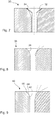
Figure 1 shows a perspective view of a first embodiment of a magnetiser according to the current invention. -
Figure 2 shows a schematic cross section view of the magnetiser offigure 1 . -
Figure 3 schematically shows the arrangement of the magnets of the magnetiser offigure 1 , showing the magnetising direction of the individual magnets. -
Figure 4 schematically shows the resulting magnetic field of the magnetiser offigure 1 . -
Figure 5 shows the flux density of the magnetic field inside the passage of the magnetiser offigure 1 around the circle defined by A infigures 3 and 4 . -
Figure 6 shows the radial (Brad) and axial (Bz) flux density in different locations along the length of the passage of the magnetiser offigure 1 along the longitudinal lines defined by the points A and B as defined infigures 3 and 4 . -
Figure 7 schematically shows a cross sectional view of a second embodiment of a magnetiser according to the current invention. -
Figure 8 shows a schematic cross sectional view of a third embodiment of a magnetiser according to the current invention. -
Figure 9 shows a schematic cross sectional view of a fourth embodiment of a magnetiser according to the current invention. -
Figure 10 shows a perspective view of a fifth embodiment of a magnetiser according to the current invention. -
Figure 11 shows a schematic perspective view of the magnetiser offigure 10 with one of the sides and one of the magnets hidden for clarity. -
Figure 12 shows a schematic cross sectional view of a sixth embodiment of a magnetiser according to the current invention. -
Figure 13 shows a schematic cross sectional view of a seventh embodiment of a magnetiser according to the current invention. - In the following, the invention will be described in greater detail with reference to embodiments shown by the enclosed figures. It should be emphasized that the embodiments shown are used for example purposes only and should not be used to limit the scope of the invention.
-
Figures 1 to 6 shows different views and charts related to afirst embodiment 1 of a permanent magnet based magnetiser according to the current invention. - The
magnetiser 1 comprises acircular array 2 of shapedpermanent magnets 4. Each of said permanent magnets having a roughly pie shaped cross section, which when arranged in a circular array form a Halbach array. The magnetizations of the individual magnets is shown infigure 3 and a partial view of the resulting magnetic field of the overall assembly is shown infigure 4 . As can be seen fromfigure 4 , the resulting assembly provides a magnetiser having a magnetic field with four poles. As will be known to the person skilled in the art, by changing the number of magnets and changing the magnetisations of the different magnets, the resulting magnetic field and the number of poles can be changed. - The magnetiser has an outer body made of
permanent magnets 4 and apassage 8 passing through the magnets. Thepassage 8 has a longitudinal centre axis L. In this embodiment, the passage has anupper opening 10 and alower opening 12. The function of the openings can be different depending on how the magnetiser is used. In the case of the magnetiser shown infigures 1 to 6 , an object to be magnetised is typically inserted into theupper opening 10 and removed again from theupper opening 10. In this case, theupper opening 10 functions as both an inlet into and an outlet from the passage. In another situation, one could imagine that an object is inserted into the passage via thelower opening 12 and removed from the passage via theupper opening 10. - The
passage 8 in the current embodiment comprises two portions: auniform portion 14 and a divergingportion 16. In the uniform portion, themagnets 4 are shaped such that the opposing surfaces of the magnets are arranged parallel to each other such that the distance between the opposing surfaces of the uniform portion are constant along the length D1 of the uniform portion. In this embodiment, since the magnetiser is arranged as a circular array of magnets, it should be understood that the opposing surfaces as discussed here are all part of the same cylindrical surface, however for the sake of this specification, opposing portions of the cylindrical surface should be understood as opposing surfaces. - Near the
outlet 10 of the passage, themagnets 4 are shaped to form a divergingportion 16. The diverging portion is arranged so that as the object leaves the passageway via the outlet, the opposingsurfaces 16 of the magnets diverge away from each other. Different dimensions are shown onfigure 2 to better describe the dimensions of the magnetiser. The length of the uniform portion along the longitudinal centre axis is shown by the dimension D1. The length of the diverging portion along a distance parallel to the longitudinal centre axis of the passage is shown by D2. The distance between the opposing surfaces of the uniform portion is shown by D3 and the maximum distance between the opposing surfaces of the diverging portion is shown by D4. The outer diameter of the circular array of magnets is shown by D5. The angle that the tangent vector to the opposing surfaces of the diverging portion makes to the longitudinal axis is shown by the angle A. The normal vector to the surface in the diverging portion is shown by the vector N. The angle of the normal vector to the longitudinal axis is 90 degrees minus the angle A. - In one concrete case D1 is 31,2mm, D2 is 8,8mm, D3 is 10mm, D4 is 15,84mm, D5 is 44mm and the angle A is 20 degrees (or the angle of the normal vector to the longitudinal centre axis is 70 degrees).
- The
magnetiser 1 is arranged with a housing (not shown) arranged around thepermanent magnets 4 to hold the magnets in place and protect them from damage. In one embodiment (not shown), the housing is made from aluminium. However, in other embodiments, the housing could be made from soft-magnetic material or non-magnetic material. -
Figure 5 shows the properties of the magnetic field inside the uniform portion of thepassage 8. The figure shows the radial (Brad) and tangential (Btan) component of the magnetic flux at different angular positions travelling around the circumference of the passageway at a distance of 2.5mm from the central axis of the passage. This is shown by the dashed circle comprising the point A as shown infigures 3 and 4 . As can be seen, the magnetic field has a very sinusoidal property which provides for a nice magnetic field in the magnetised object. -
Figure 6 shows the different components of the magnetic field at different longitudinal positions along the longitudinal axis of the passage. Two different paths are shown in the figure. The first path is a longitudinal line offset 2.5mm from the longitudinal centre axis (point A infigures 3 and 4 ) and the second path is a longitudinal line offset 3.7mm (point B infigures 3 and 4 ) from the longitudinal centre axis. One can imagine the figure is the result of the measurement of the magnetic field as one travels along the longitudinal line through the passage. The Z-coordinate shown on the x-axis in the figure is the position along the longitudinal centre axis. The position 0mm is right in the middle of the passage. Likewise, the positions -40 and +40 are located outside the passage. As can be seen the Radial components (Brad) in the centre of the passage are very uniform and the z components (Bz) are very small. However, near the inlet and the outlet, the z-components of the magnetic field get quite large. On the left side of the figure (from around -30 to -10), the field is shown at thelower opening 12 of the passage and to the right in the figure (from around 10 to 30), the field is shown at theupper opening 10. As can be seen the z-component effects at theupper opening 10 are much reduced when compared to the z-component effects at thelower opening 12. At the upper opening, the z-component effect is less than 0.2 T at 3.7mm from the centre while the z-component effect at the lower opening is around 0.4T. This means that the Z component effect is reduced by at least half by providing the diverging portion at the outlet of the passage. - It can be noted that should the reduction in z-component be required at both
openings upper openings -
Figure 7 shows anembodiment 30, where asleeve 32 has been provided to protect the magnet from damage. An extraangled portion 34 has been provided at the upper portion of the diverging portion. This extra angled portion allows a good seat of the sleeve. In this embodiment, it can be said that the average angle of the diverging portion is greater than in the embodiment offigures 1 to 6 , however one can see that the first portion is around 20 degrees and the second portion is around 40 degrees. However, the change between uniform portion is 20 degrees and then a further change of 20 degrees is made. Hence the average rate of change of the angle of the diverging surface is not so large. In this embodiment, the sleeve is made from stainless steel so that the magnetic properties of the magnets are not affected so much. Other materials could also be used for the sleeve . In one case, the sleeve is made from a magnetically permeable material. This embodiment is constructed from a magnet assembly similar to the embodiment shown infigures 1-6 . -
Figure 8 shows anotherembodiment 36 similar to the embodiment offigures 1 to 6 , but where instead of a diverging portion with a linear diverging surface, in this case, the diverging surface is acurved surface 38. In this case, the rate of change of the tangent angle along the surface is around 2 degrees per mm. However, it could be said that the average rate of change of the diverging surface could be less than 4 degrees per mm, less than 3 degrees per mm or less than 2 degrees per mm. -
Figure 9 shows anotherembodiment 40 similar to the embodiment offigures 1 to 6 but where instead of one linear diverging surface, the diverging surface comprises threeindividual portions -
Figure 10 shows anexample embodiment 50 of a di-pole magnetiser. In this case, twopermanent magnets passage 56. A first and second magnetic conductingplate upper portion curved entrance 66 andexit 68 and a uniformcentral portion 70. Apassage 56 is arranged between the curved surfaces. An object can be introduced into the passage at one end and moved through the passage to the other end to magnetize the object. - In this case, the
passage 56 has two opposingparallel surfaces 66 and is open at the top and closed at the bottom. The magnetic field is arranged to pass essentially perpendicular through the passage from one opposing surface to the other at the central portion (uniform portion) 66 of thepassage 56. Each end of the passage is formed as a diverging surface. Hence, the object to be magnetized can be inserted from either end and removed from either end. As such both entrances work as either inlet or outlet. -
Figure 12 shows anotherembodiment 80, where a number ofpermanent magnets 82 are lined with aprotective lining 84. The magnets however still have theuniform portion 86 defining the passage with parallel side walls and a divergingportion 88 with diverging opposing surfaces. The magnets are in this case arranged as a circular array as in the embodiment offigures 1 to 6 . Together, themagnets 82 and theprotective lining 84 form a permanent magnetic assembly. -
Figure 13 shows anotherembodiment 90, where thepermanent magnets 92 are more rectangular in their cross section, but a core lining 94 made of a magnetic permeable material is provided with the inner uniform surfaces 96 and the diverging surfaces 98. As before thepermanent magnets 92 and the core lining 94 together form a permanent magnet assembly. - It is to be noted that the figures and the above description have shown the example embodiments in a simple and schematic manner. Many of the specific mechanical details have not been shown since the person skilled in the art should be familiar with these details and they would just unnecessarily complicate this description. For example, the specific materials used and the specific manufacturing procedures have not been described in detail since it is maintained that the person skilled in the art would be able to find suitable materials and suitable processes to manufacture the magnetiser according to the current invention.
Claims (10)
- A magnetiser comprising a housing, a passage arranged inside the housing, and a permanent magnet assembly arranged outside the passage to provide a magnetic field passing through the passage, said housing comprising an inlet to the passage and an outlet from the passage such that an object to be magnetised can be inserted into the passage via the inlet in the housing and removed via the outlet in the housing, characterized in that the passage comprisesa. a uniform portion where opposing surfaces of the permanent magnet assembly are arranged a uniform distance apart along the length of the uniform portion andb. a diverging portion arranged between one end of the uniform portion of the passage and the outlet of the housing where opposing surfaces of the permanent magnet assembly diverge such that the distance between opposing surfaces of the diverging portion nearest the uniform portion is less than the distance between opposing surfaces of the diverging portion nearest the outlet and in thatc. the average angle of the normal vector of the opposing surfaces of the diverging portion to a longitudinal centre axis of the passage is greater than 45 degrees.
- A magnetiser according to claim 1, characterized in that the permanent magnet assembly comprises a permanent magnet arranged outside the passage and an insert arranged between the permanent magnet and the passage, said insert being made of a material having a relative magnetic permeability greater than 1.
- A magnetiser according to claims 1 or 2, characterized in that the distance D4 between opposing surfaces of the diverging portion nearest the outlet is at least 1.2 times greater than the distance D3 between the opposing surfaces of the uniform portion.
- A magnetiser according to any one of claims 1 to 3, characterized in that the length D2 of the diverging portion in a direction parallel to the longitudinal centre axis of the passage is greater than 0,5 times the distance D3 between the opposing surfaces of the uniform portion.
- A magnetiser according to any one of claims 1 to 4, characterized in that the inlet and the outlet in the housing are the same opening, such that the object to be magnetised is introduced into and removed from the passage via the same opening in the housing.
- A magnetiser according to any one of claims 1 to 4, characterized in that the inlet and the outlet in the housing are two different openings in the housing such that the object to be magnetised enters the passage via the inlet and leaves the passage via the outlet.
- A magnetiser according to any one of claims 1 to 6, characterized in that the permanent magnet assembly comprises a circular array of magnets arranged around the periphery of the passage.
- A magnetiser according to any one of claims 1 to 7, characterized in that the permanent magnet assembly comprises an array of magnets arranged as a Halbach array.
- A magnetiser according to any one of claims 1 to 8, characterized in that the permanent magnet assembly is arranged to provide at least a two-pole magnetic field in the uniform portion of the passage.
- A magnetising mechanism comprising a magnetiser according to any one of claims 1 to 9 and an actuator, said actuator being arranged to repeatedly move the magnetiser from a first position to a second position, said first position being arranged such that the passage is located away from an object to be magnetised and said second position being arranged such that the uniform portion of the passage of the magnetiser is arranged around the object to be magnetised.
Priority Applications (4)
| Application Number | Priority Date | Filing Date | Title |
|---|---|---|---|
| EP19199709.7A EP3799086B1 (en) | 2019-09-25 | 2019-09-25 | Permanent magnet based magnetiser |
| US17/763,874 US12002619B2 (en) | 2019-09-25 | 2020-09-25 | Permanent magnet based magnetiser |
| PCT/EP2020/076973 WO2021058779A1 (en) | 2019-09-25 | 2020-09-25 | Permanent magnet based magnetiser |
| CN202080067652.0A CN114514588A (en) | 2019-09-25 | 2020-09-25 | Magnetizer based on permanent magnet |
Applications Claiming Priority (1)
| Application Number | Priority Date | Filing Date | Title |
|---|---|---|---|
| EP19199709.7A EP3799086B1 (en) | 2019-09-25 | 2019-09-25 | Permanent magnet based magnetiser |
Publications (3)
| Publication Number | Publication Date |
|---|---|
| EP3799086A1 true EP3799086A1 (en) | 2021-03-31 |
| EP3799086B1 EP3799086B1 (en) | 2024-03-27 |
| EP3799086C0 EP3799086C0 (en) | 2024-03-27 |
Family
ID=68069625
Family Applications (1)
| Application Number | Title | Priority Date | Filing Date |
|---|---|---|---|
| EP19199709.7A Active EP3799086B1 (en) | 2019-09-25 | 2019-09-25 | Permanent magnet based magnetiser |
Country Status (4)
| Country | Link |
|---|---|
| US (1) | US12002619B2 (en) |
| EP (1) | EP3799086B1 (en) |
| CN (1) | CN114514588A (en) |
| WO (1) | WO2021058779A1 (en) |
Cited By (1)
| Publication number | Priority date | Publication date | Assignee | Title |
|---|---|---|---|---|
| CN115786647A (en) * | 2022-12-19 | 2023-03-14 | 江苏龙城精锻集团有限公司 | Manufacturing method for regulating heat treatment deformation of similar magnetizer inductor |
Citations (3)
| Publication number | Priority date | Publication date | Assignee | Title |
|---|---|---|---|---|
| US3662303A (en) * | 1971-03-08 | 1972-05-09 | Anatoli Arllof | Instant magnetizer and demagnetizer |
| US20130192723A1 (en) * | 2012-01-31 | 2013-08-01 | Minebea Co., Ltd. | Method for manufacturing bonded magnet |
| CN103971878B (en) * | 2014-05-20 | 2016-08-31 | 北京京磁电工科技有限公司 | Magnetic charging system |
Family Cites Families (7)
| Publication number | Priority date | Publication date | Assignee | Title |
|---|---|---|---|---|
| JPS6312110A (en) * | 1986-03-14 | 1988-01-19 | Asahi Chem Ind Co Ltd | Uniform magnetic field generator |
| US6225887B1 (en) * | 1996-11-22 | 2001-05-01 | New York University | Generation of highly uniform magnetic fields with magnetized wedges |
| JP4338302B2 (en) | 2000-11-14 | 2009-10-07 | 三菱電機株式会社 | Electromagnet device |
| FR2949601A1 (en) * | 2009-08-28 | 2011-03-04 | Commissariat Energie Atomique | PERMANENT MAGNETIC FIELD MAGNETIC FIELD DEVICE INDUCED WITH PREDETERMINED ORIENTATION AND METHOD FOR MANUFACTURING THE SAME |
| US8358190B1 (en) * | 2011-09-26 | 2013-01-22 | The United States Of America As Represented By The Secretary Of The Air Force | Permanent magnet structure for producing a uniform axial magnetic field |
| CN102412051B (en) | 2011-12-09 | 2014-04-09 | 西南应用磁学研究所 | Permanent magnet assembly with high-intensity magnetic field and high uniformity |
| DE102014225900A1 (en) | 2014-12-15 | 2016-06-16 | Robert Bosch Gmbh | Apparatus and method for magnetizing permanent magnets |
-
2019
- 2019-09-25 EP EP19199709.7A patent/EP3799086B1/en active Active
-
2020
- 2020-09-25 CN CN202080067652.0A patent/CN114514588A/en active Pending
- 2020-09-25 WO PCT/EP2020/076973 patent/WO2021058779A1/en not_active Ceased
- 2020-09-25 US US17/763,874 patent/US12002619B2/en active Active
Patent Citations (3)
| Publication number | Priority date | Publication date | Assignee | Title |
|---|---|---|---|---|
| US3662303A (en) * | 1971-03-08 | 1972-05-09 | Anatoli Arllof | Instant magnetizer and demagnetizer |
| US20130192723A1 (en) * | 2012-01-31 | 2013-08-01 | Minebea Co., Ltd. | Method for manufacturing bonded magnet |
| CN103971878B (en) * | 2014-05-20 | 2016-08-31 | 北京京磁电工科技有限公司 | Magnetic charging system |
Cited By (1)
| Publication number | Priority date | Publication date | Assignee | Title |
|---|---|---|---|---|
| CN115786647A (en) * | 2022-12-19 | 2023-03-14 | 江苏龙城精锻集团有限公司 | Manufacturing method for regulating heat treatment deformation of similar magnetizer inductor |
Also Published As
| Publication number | Publication date |
|---|---|
| EP3799086B1 (en) | 2024-03-27 |
| WO2021058779A1 (en) | 2021-04-01 |
| US12002619B2 (en) | 2024-06-04 |
| EP3799086C0 (en) | 2024-03-27 |
| US20220336135A1 (en) | 2022-10-20 |
| CN114514588A (en) | 2022-05-17 |
Similar Documents
| Publication | Publication Date | Title |
|---|---|---|
| US8536861B2 (en) | Wire rope flaw detector | |
| US4355236A (en) | Variable strength beam line multipole permanent magnets and methods for their use | |
| US8415838B1 (en) | Linear motor with two magnets and a coil carrier having multiple winding areas with each area having a section of a coil wound with one continuous wire with the winding in opposite directions in spaced apart winding areas | |
| ES2335388T3 (en) | SHORT RACE ELECTRICAL LINEAR ACTUATOR. | |
| CS213709B1 (en) | Anizotropous permanent magnets | |
| EP3799086B1 (en) | Permanent magnet based magnetiser | |
| CN114400806A (en) | Rotating electrical machine | |
| CN105529883A (en) | Method for manufacturing an interior permanent magnet rotor unit and magnetizing device | |
| JPH0461483B2 (en) | ||
| JP2020049479A (en) | Magnet filter and outer pipe | |
| US11482899B2 (en) | Rotating electrical machine with rotor having arc shaped permanent magnets | |
| CN110885116B (en) | A water magnetization device | |
| CN209872468U (en) | Water magnetizing device | |
| JP2021083289A (en) | Manufacturing method and manufacturing device of permanent magnet rotor | |
| JP2000040616A (en) | Orientation device and magnetization device for ring-shaped permanent magnet | |
| JP4013916B2 (en) | Orientation processing device for anisotropic bonded magnet for 4-pole motor | |
| GB2069766A (en) | Improvements in or relating to methods of producing anisotropic permanent magnets and magnets produced by such methods | |
| JPS61262063A (en) | Cylindrical direct-acting motor | |
| EP0579598B1 (en) | Permanent magnet assembly | |
| JP2001258235A (en) | Linear actuator | |
| EP1655745A1 (en) | Inductor | |
| RU98104229A (en) | MAGNET TUNNEL | |
| WO1992018993A1 (en) | Permanent magnet assembly | |
| JPH0260035A (en) | Permanent magnet for electron lens | |
| JP4737202B2 (en) | Method for orienting anisotropic bonded magnet for motor |
Legal Events
| Date | Code | Title | Description |
|---|---|---|---|
| PUAI | Public reference made under article 153(3) epc to a published international application that has entered the european phase |
Free format text: ORIGINAL CODE: 0009012 |
|
| STAA | Information on the status of an ep patent application or granted ep patent |
Free format text: STATUS: THE APPLICATION HAS BEEN PUBLISHED |
|
| AK | Designated contracting states |
Kind code of ref document: A1 Designated state(s): AL AT BE BG CH CY CZ DE DK EE ES FI FR GB GR HR HU IE IS IT LI LT LU LV MC MK MT NL NO PL PT RO RS SE SI SK SM TR |
|
| AX | Request for extension of the european patent |
Extension state: BA ME |
|
| STAA | Information on the status of an ep patent application or granted ep patent |
Free format text: STATUS: REQUEST FOR EXAMINATION WAS MADE |
|
| 17P | Request for examination filed |
Effective date: 20210930 |
|
| RBV | Designated contracting states (corrected) |
Designated state(s): AL AT BE BG CH CY CZ DE DK EE ES FI FR GB GR HR HU IE IS IT LI LT LU LV MC MK MT NL NO PL PT RO RS SE SI SK SM TR |
|
| GRAP | Despatch of communication of intention to grant a patent |
Free format text: ORIGINAL CODE: EPIDOSNIGR1 |
|
| STAA | Information on the status of an ep patent application or granted ep patent |
Free format text: STATUS: GRANT OF PATENT IS INTENDED |
|
| INTG | Intention to grant announced |
Effective date: 20230425 |
|
| GRAJ | Information related to disapproval of communication of intention to grant by the applicant or resumption of examination proceedings by the epo deleted |
Free format text: ORIGINAL CODE: EPIDOSDIGR1 |
|
| STAA | Information on the status of an ep patent application or granted ep patent |
Free format text: STATUS: REQUEST FOR EXAMINATION WAS MADE |
|
| INTC | Intention to grant announced (deleted) | ||
| GRAP | Despatch of communication of intention to grant a patent |
Free format text: ORIGINAL CODE: EPIDOSNIGR1 |
|
| STAA | Information on the status of an ep patent application or granted ep patent |
Free format text: STATUS: GRANT OF PATENT IS INTENDED |
|
| INTG | Intention to grant announced |
Effective date: 20231110 |
|
| GRAS | Grant fee paid |
Free format text: ORIGINAL CODE: EPIDOSNIGR3 |
|
| GRAA | (expected) grant |
Free format text: ORIGINAL CODE: 0009210 |
|
| STAA | Information on the status of an ep patent application or granted ep patent |
Free format text: STATUS: THE PATENT HAS BEEN GRANTED |
|
| AK | Designated contracting states |
Kind code of ref document: B1 Designated state(s): AL AT BE BG CH CY CZ DE DK EE ES FI FR GB GR HR HU IE IS IT LI LT LU LV MC MK MT NL NO PL PT RO RS SE SI SK SM TR |
|
| REG | Reference to a national code |
Ref country code: GB Ref legal event code: FG4D |
|
| REG | Reference to a national code |
Ref country code: CH Ref legal event code: EP |
|
| REG | Reference to a national code |
Ref country code: DE Ref legal event code: R096 Ref document number: 602019048919 Country of ref document: DE |
|
| REG | Reference to a national code |
Ref country code: IE Ref legal event code: FG4D |
|
| U01 | Request for unitary effect filed |
Effective date: 20240423 |
|
| U07 | Unitary effect registered |
Designated state(s): AT BE BG DE DK EE FI FR IT LT LU LV MT NL PT SE SI Effective date: 20240430 |
|
| PG25 | Lapsed in a contracting state [announced via postgrant information from national office to epo] |
Ref country code: GR Free format text: LAPSE BECAUSE OF FAILURE TO SUBMIT A TRANSLATION OF THE DESCRIPTION OR TO PAY THE FEE WITHIN THE PRESCRIBED TIME-LIMIT Effective date: 20240628 |
|
| PG25 | Lapsed in a contracting state [announced via postgrant information from national office to epo] |
Ref country code: HR Free format text: LAPSE BECAUSE OF FAILURE TO SUBMIT A TRANSLATION OF THE DESCRIPTION OR TO PAY THE FEE WITHIN THE PRESCRIBED TIME-LIMIT Effective date: 20240327 Ref country code: RS Free format text: LAPSE BECAUSE OF FAILURE TO SUBMIT A TRANSLATION OF THE DESCRIPTION OR TO PAY THE FEE WITHIN THE PRESCRIBED TIME-LIMIT Effective date: 20240627 |
|
| PG25 | Lapsed in a contracting state [announced via postgrant information from national office to epo] |
Ref country code: RS Free format text: LAPSE BECAUSE OF FAILURE TO SUBMIT A TRANSLATION OF THE DESCRIPTION OR TO PAY THE FEE WITHIN THE PRESCRIBED TIME-LIMIT Effective date: 20240627 Ref country code: NO Free format text: LAPSE BECAUSE OF FAILURE TO SUBMIT A TRANSLATION OF THE DESCRIPTION OR TO PAY THE FEE WITHIN THE PRESCRIBED TIME-LIMIT Effective date: 20240627 Ref country code: HR Free format text: LAPSE BECAUSE OF FAILURE TO SUBMIT A TRANSLATION OF THE DESCRIPTION OR TO PAY THE FEE WITHIN THE PRESCRIBED TIME-LIMIT Effective date: 20240327 Ref country code: GR Free format text: LAPSE BECAUSE OF FAILURE TO SUBMIT A TRANSLATION OF THE DESCRIPTION OR TO PAY THE FEE WITHIN THE PRESCRIBED TIME-LIMIT Effective date: 20240628 |
|
| PG25 | Lapsed in a contracting state [announced via postgrant information from national office to epo] |
Ref country code: IS Free format text: LAPSE BECAUSE OF FAILURE TO SUBMIT A TRANSLATION OF THE DESCRIPTION OR TO PAY THE FEE WITHIN THE PRESCRIBED TIME-LIMIT Effective date: 20240727 |
|
| PG25 | Lapsed in a contracting state [announced via postgrant information from national office to epo] |
Ref country code: SM Free format text: LAPSE BECAUSE OF FAILURE TO SUBMIT A TRANSLATION OF THE DESCRIPTION OR TO PAY THE FEE WITHIN THE PRESCRIBED TIME-LIMIT Effective date: 20240327 |
|
| PG25 | Lapsed in a contracting state [announced via postgrant information from national office to epo] |
Ref country code: ES Free format text: LAPSE BECAUSE OF FAILURE TO SUBMIT A TRANSLATION OF THE DESCRIPTION OR TO PAY THE FEE WITHIN THE PRESCRIBED TIME-LIMIT Effective date: 20240327 |
|
| PG25 | Lapsed in a contracting state [announced via postgrant information from national office to epo] |
Ref country code: CZ Free format text: LAPSE BECAUSE OF FAILURE TO SUBMIT A TRANSLATION OF THE DESCRIPTION OR TO PAY THE FEE WITHIN THE PRESCRIBED TIME-LIMIT Effective date: 20240327 |
|
| PG25 | Lapsed in a contracting state [announced via postgrant information from national office to epo] |
Ref country code: PL Free format text: LAPSE BECAUSE OF FAILURE TO SUBMIT A TRANSLATION OF THE DESCRIPTION OR TO PAY THE FEE WITHIN THE PRESCRIBED TIME-LIMIT Effective date: 20240327 |
|
| PG25 | Lapsed in a contracting state [announced via postgrant information from national office to epo] |
Ref country code: SK Free format text: LAPSE BECAUSE OF FAILURE TO SUBMIT A TRANSLATION OF THE DESCRIPTION OR TO PAY THE FEE WITHIN THE PRESCRIBED TIME-LIMIT Effective date: 20240327 |
|
| U20 | Renewal fee for the european patent with unitary effect paid |
Year of fee payment: 6 Effective date: 20240925 |
|
| PG25 | Lapsed in a contracting state [announced via postgrant information from national office to epo] |
Ref country code: SM Free format text: LAPSE BECAUSE OF FAILURE TO SUBMIT A TRANSLATION OF THE DESCRIPTION OR TO PAY THE FEE WITHIN THE PRESCRIBED TIME-LIMIT Effective date: 20240327 Ref country code: SK Free format text: LAPSE BECAUSE OF FAILURE TO SUBMIT A TRANSLATION OF THE DESCRIPTION OR TO PAY THE FEE WITHIN THE PRESCRIBED TIME-LIMIT Effective date: 20240327 Ref country code: RO Free format text: LAPSE BECAUSE OF FAILURE TO SUBMIT A TRANSLATION OF THE DESCRIPTION OR TO PAY THE FEE WITHIN THE PRESCRIBED TIME-LIMIT Effective date: 20240327 Ref country code: PL Free format text: LAPSE BECAUSE OF FAILURE TO SUBMIT A TRANSLATION OF THE DESCRIPTION OR TO PAY THE FEE WITHIN THE PRESCRIBED TIME-LIMIT Effective date: 20240327 Ref country code: IS Free format text: LAPSE BECAUSE OF FAILURE TO SUBMIT A TRANSLATION OF THE DESCRIPTION OR TO PAY THE FEE WITHIN THE PRESCRIBED TIME-LIMIT Effective date: 20240727 Ref country code: ES Free format text: LAPSE BECAUSE OF FAILURE TO SUBMIT A TRANSLATION OF THE DESCRIPTION OR TO PAY THE FEE WITHIN THE PRESCRIBED TIME-LIMIT Effective date: 20240327 Ref country code: CZ Free format text: LAPSE BECAUSE OF FAILURE TO SUBMIT A TRANSLATION OF THE DESCRIPTION OR TO PAY THE FEE WITHIN THE PRESCRIBED TIME-LIMIT Effective date: 20240327 |
|
| REG | Reference to a national code |
Ref country code: DE Ref legal event code: R097 Ref document number: 602019048919 Country of ref document: DE |
|
| PLBE | No opposition filed within time limit |
Free format text: ORIGINAL CODE: 0009261 |
|
| STAA | Information on the status of an ep patent application or granted ep patent |
Free format text: STATUS: NO OPPOSITION FILED WITHIN TIME LIMIT |
|
| 26N | No opposition filed |
Effective date: 20250103 |
|
| PG25 | Lapsed in a contracting state [announced via postgrant information from national office to epo] |
Ref country code: MC Free format text: LAPSE BECAUSE OF FAILURE TO SUBMIT A TRANSLATION OF THE DESCRIPTION OR TO PAY THE FEE WITHIN THE PRESCRIBED TIME-LIMIT Effective date: 20240327 |
|
| REG | Reference to a national code |
Ref country code: CH Ref legal event code: PL |
|
| GBPC | Gb: european patent ceased through non-payment of renewal fee |
Effective date: 20240925 |
|
| PG25 | Lapsed in a contracting state [announced via postgrant information from national office to epo] |
Ref country code: GB Free format text: LAPSE BECAUSE OF NON-PAYMENT OF DUE FEES Effective date: 20240925 |
|
| PG25 | Lapsed in a contracting state [announced via postgrant information from national office to epo] |
Ref country code: CH Free format text: LAPSE BECAUSE OF NON-PAYMENT OF DUE FEES Effective date: 20240930 |
|
| PG25 | Lapsed in a contracting state [announced via postgrant information from national office to epo] |
Ref country code: IE Free format text: LAPSE BECAUSE OF NON-PAYMENT OF DUE FEES Effective date: 20240925 |
|
| PG25 | Lapsed in a contracting state [announced via postgrant information from national office to epo] |
Ref country code: CY Free format text: LAPSE BECAUSE OF FAILURE TO SUBMIT A TRANSLATION OF THE DESCRIPTION OR TO PAY THE FEE WITHIN THE PRESCRIBED TIME-LIMIT; INVALID AB INITIO Effective date: 20190925 |
|
| PG25 | Lapsed in a contracting state [announced via postgrant information from national office to epo] |
Ref country code: HU Free format text: LAPSE BECAUSE OF FAILURE TO SUBMIT A TRANSLATION OF THE DESCRIPTION OR TO PAY THE FEE WITHIN THE PRESCRIBED TIME-LIMIT; INVALID AB INITIO Effective date: 20190925 |
|
| U90 | Renewal fees not paid: noting of loss of rights |
Free format text: RENEWAL FEE NOT PAID FOR YEAR 07 Effective date: 20260417 |
|
| PG25 | Lapsed in a contracting state [announced via postgrant information from national office to epo] |
Ref country code: TR Free format text: LAPSE BECAUSE OF FAILURE TO SUBMIT A TRANSLATION OF THE DESCRIPTION OR TO PAY THE FEE WITHIN THE PRESCRIBED TIME-LIMIT Effective date: 20240327 |
|
| U93 | Unitary patent lapsed |
Free format text: RENEWAL FEE NOT PAID Effective date: 20250930 |