EP3798811A1 - Icon display method and device, terminal, and storage medium - Google Patents
Icon display method and device, terminal, and storage medium Download PDFInfo
- Publication number
- EP3798811A1 EP3798811A1 EP19815186.2A EP19815186A EP3798811A1 EP 3798811 A1 EP3798811 A1 EP 3798811A1 EP 19815186 A EP19815186 A EP 19815186A EP 3798811 A1 EP3798811 A1 EP 3798811A1
- Authority
- EP
- European Patent Office
- Prior art keywords
- function icons
- function
- icons
- region
- target region
- Prior art date
- Legal status (The legal status is an assumption and is not a legal conclusion. Google has not performed a legal analysis and makes no representation as to the accuracy of the status listed.)
- Granted
Links
Images






Classifications
-
- G—PHYSICS
- G06—COMPUTING OR CALCULATING; COUNTING
- G06F—ELECTRIC DIGITAL DATA PROCESSING
- G06F3/00—Input arrangements for transferring data to be processed into a form capable of being handled by the computer; Output arrangements for transferring data from processing unit to output unit, e.g. interface arrangements
- G06F3/01—Input arrangements or combined input and output arrangements for interaction between user and computer
- G06F3/048—Interaction techniques based on graphical user interfaces [GUI]
- G06F3/0481—Interaction techniques based on graphical user interfaces [GUI] based on specific properties of the displayed interaction object or a metaphor-based environment, e.g. interaction with desktop elements like windows or icons, or assisted by a cursor's changing behaviour or appearance
- G06F3/0482—Interaction with lists of selectable items, e.g. menus
-
- G—PHYSICS
- G06—COMPUTING OR CALCULATING; COUNTING
- G06F—ELECTRIC DIGITAL DATA PROCESSING
- G06F3/00—Input arrangements for transferring data to be processed into a form capable of being handled by the computer; Output arrangements for transferring data from processing unit to output unit, e.g. interface arrangements
- G06F3/01—Input arrangements or combined input and output arrangements for interaction between user and computer
- G06F3/048—Interaction techniques based on graphical user interfaces [GUI]
- G06F3/0481—Interaction techniques based on graphical user interfaces [GUI] based on specific properties of the displayed interaction object or a metaphor-based environment, e.g. interaction with desktop elements like windows or icons, or assisted by a cursor's changing behaviour or appearance
- G06F3/04817—Interaction techniques based on graphical user interfaces [GUI] based on specific properties of the displayed interaction object or a metaphor-based environment, e.g. interaction with desktop elements like windows or icons, or assisted by a cursor's changing behaviour or appearance using icons
-
- G—PHYSICS
- G06—COMPUTING OR CALCULATING; COUNTING
- G06F—ELECTRIC DIGITAL DATA PROCESSING
- G06F3/00—Input arrangements for transferring data to be processed into a form capable of being handled by the computer; Output arrangements for transferring data from processing unit to output unit, e.g. interface arrangements
- G06F3/01—Input arrangements or combined input and output arrangements for interaction between user and computer
- G06F3/048—Interaction techniques based on graphical user interfaces [GUI]
- G06F3/0484—Interaction techniques based on graphical user interfaces [GUI] for the control of specific functions or operations, e.g. selecting or manipulating an object, an image or a displayed text element, setting a parameter value or selecting a range
- G06F3/04847—Interaction techniques to control parameter settings, e.g. interaction with sliders or dials
-
- G—PHYSICS
- G06—COMPUTING OR CALCULATING; COUNTING
- G06F—ELECTRIC DIGITAL DATA PROCESSING
- G06F3/00—Input arrangements for transferring data to be processed into a form capable of being handled by the computer; Output arrangements for transferring data from processing unit to output unit, e.g. interface arrangements
- G06F3/01—Input arrangements or combined input and output arrangements for interaction between user and computer
- G06F3/048—Interaction techniques based on graphical user interfaces [GUI]
- G06F3/0484—Interaction techniques based on graphical user interfaces [GUI] for the control of specific functions or operations, e.g. selecting or manipulating an object, an image or a displayed text element, setting a parameter value or selecting a range
- G06F3/0485—Scrolling or panning
-
- G—PHYSICS
- G06—COMPUTING OR CALCULATING; COUNTING
- G06F—ELECTRIC DIGITAL DATA PROCESSING
- G06F3/00—Input arrangements for transferring data to be processed into a form capable of being handled by the computer; Output arrangements for transferring data from processing unit to output unit, e.g. interface arrangements
- G06F3/01—Input arrangements or combined input and output arrangements for interaction between user and computer
- G06F3/048—Interaction techniques based on graphical user interfaces [GUI]
- G06F3/0487—Interaction techniques based on graphical user interfaces [GUI] using specific features provided by the input device, e.g. functions controlled by the rotation of a mouse with dual sensing arrangements, or of the nature of the input device, e.g. tap gestures based on pressure sensed by a digitiser
- G06F3/0488—Interaction techniques based on graphical user interfaces [GUI] using specific features provided by the input device, e.g. functions controlled by the rotation of a mouse with dual sensing arrangements, or of the nature of the input device, e.g. tap gestures based on pressure sensed by a digitiser using a touch-screen or digitiser, e.g. input of commands through traced gestures
-
- G—PHYSICS
- G06—COMPUTING OR CALCULATING; COUNTING
- G06F—ELECTRIC DIGITAL DATA PROCESSING
- G06F3/00—Input arrangements for transferring data to be processed into a form capable of being handled by the computer; Output arrangements for transferring data from processing unit to output unit, e.g. interface arrangements
- G06F3/01—Input arrangements or combined input and output arrangements for interaction between user and computer
- G06F3/048—Interaction techniques based on graphical user interfaces [GUI]
- G06F3/0487—Interaction techniques based on graphical user interfaces [GUI] using specific features provided by the input device, e.g. functions controlled by the rotation of a mouse with dual sensing arrangements, or of the nature of the input device, e.g. tap gestures based on pressure sensed by a digitiser
- G06F3/0488—Interaction techniques based on graphical user interfaces [GUI] using specific features provided by the input device, e.g. functions controlled by the rotation of a mouse with dual sensing arrangements, or of the nature of the input device, e.g. tap gestures based on pressure sensed by a digitiser using a touch-screen or digitiser, e.g. input of commands through traced gestures
- G06F3/04883—Interaction techniques based on graphical user interfaces [GUI] using specific features provided by the input device, e.g. functions controlled by the rotation of a mouse with dual sensing arrangements, or of the nature of the input device, e.g. tap gestures based on pressure sensed by a digitiser using a touch-screen or digitiser, e.g. input of commands through traced gestures for inputting data by handwriting, e.g. gesture or text
Definitions
- the present disclosure relates to the field of computer technologies, and more particularly, to a method, device, terminal, and storage medium for displaying icons.
- Mobile terminals may implement various functions with different applications.
- the user when a user needs to use a specified application in a mobile terminal, the user may search for an activation icon of the specified application on the desktop of the mobile terminal, and the specified application may be activated when the activation icon is clicked.
- the embodiments of the present disclosure provide a method, device, terminal, and storage medium for displaying icons, as follows:
- a method for displaying icons is provided.
- the method is applied to a terminal comprising a special-shaped screen, the special-shaped screen comprising a special-shaped notch region; the method comprising:
- a device for displaying icons are provided.
- the device is applied to a terminal comprising a special-shaped screen.
- the special-shaped screen includes a special-shaped notch region; the device includes: an icon determining module, configured to determine Q first function icons and (P-Q) second function icons each included in P function icons; wherein Q is a preset positive integer, and P is an integer greater than Q; a first icon display module, configured to arrange and display the Q first function icons along an arc in a first target region; the first target region being a display region attached to an edge of the special-shaped screen or surrounding the special-shaped notch region; and a second icon display module, configured to display K second function icons in a current user interface when an icon display instruction applied to the first target region being detected, wherein K is an integer not greater than (P-Q).
- a terminal in a third aspect, included a processor and a memory.
- the memory stores and at least one instruction, and the instruction is loaded and executed by the processor to perform the above method for displaying icons.
- a computer-readable storage medium stores at least one instruction, and the instruction is loaded and executed by a processor to perform the above method for displaying icons.
- the special-shaped screen defines a special-shaped notch region.
- the terminal is configured to determine Q first function icons and P to Q second function icons among P function icons, where Q is a positive integer in a preset value, and P is an integer greater than Q.
- the Q first function icons are displayed in an arc arrangement in a target region, and the target region is a display region that is attached to an edge of the special-shaped screen or surrounds the special-shaped notch region.
- K second function icons are displayed in a current user interface, and K is an integer not greater than (P - Q).
- the terminal can display the originally hidden function icons in the user interface for reposing to the action of the icon display instruction, which enables the user to activate the specified application through the function icon. Operations for to search for the icon of the specified application may be simplified, a speed at which the terminal displays the function icon of the specified application may be increased, an efficiency of activating the specified application is therefore improved.
- a first target region refers to a display region that attached to the edge of the special-shaped screen or surrounds the special-shaped notch region in the special-shaped screen.
- the first target region may be transparent in a display layer.
- the first target region may also be colored in the display layer.
- the icon display instruction may be applied on the first target region.
- the first target region may have first arc-shaped.
- the first target region may also be a rectangular region.
- the first target region may also be a region in other shapes, which is not limited in the embodiment of the present disclosure. It should be noted that, for the sake of understanding, the following takes the target region having the first arc-shaped as an example.
- a first arc-shaped display bar refers to a display region having an arc-shaped in the special-shaped screen.
- the first arc-shaped display bar is configured to display function icons. For example, an icon of application A is displayed in the first arc-shaped display bar, and the icon of application A is a function icon.
- the first arc-shaped bar is an arc-shaped display region surrounding the special-shaped notch region of the special-shaped screen.
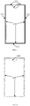
- FIG. 1 illustrates a schematic view of a display mode of the first arc-shaped bar, in accordance with an embodiment of present disclosure.
- the first arc-shaped display bar 110 is displayed around the special-shaped notch region 120.
- Icons of a first application is displayed in the first arc-shaped display bar 110.
- the icons of the first application may include at least one of a function icon 111, a function icon 112, a function icon 113, a function icon 114, a function icon 115, a function icon 116, and a function icon 117.
- first arc-shaped display bar 110 there may be one or at least two first arc-shaped display bar 110.
- the number of the first arc-shaped display bar is not limited in the embodiments of the present disclosure.
- the first arc-shaped display bar 110 may be divided into several sub-regions. Each one of the sub-regions can be individually displayed in the user interface in response to a corresponding trigger gesture.
- the following possible implementations may illustrate the details.
- the first arc-shaped display bar 110 may be divided into three sub-regions including a first sub-region, a second sub-region, and a third sub-region.
- the function icon 111, the function icon 112, and the function icon 113 are displayed in the first sub-region 110a.
- the function icon 114 is displayed in the second sub-region 110b.
- the function icon 115, the function icon 116, and the function icon 117 are displayed in the third sub-region 110c.
- the first arc-shaped display bar may be triggered when the terminal is in a horizontal display state, or when the terminal is in a vertical display state.
- the first arc-shaped display bar may be triggered to display on the special-shaped screen when the terminal is in a horizontal display state.
- FIG. 2 illustrates a schematic view of another display mode of the first arc-shaped display region, in accordance with an embodiment of present disclosure.
- the first arc-shaped bar is triggered to display when the terminal is in the vertical display state.
- a Function icon refers to a virtual icon displayed in the first arc-shaped display bar.
- the function icon may be an activation icon of an in-system application or a third-party application.
- the function icon may also be an activation icon of a system service or a system process.
- the in-system application may include at least one in-system applications selected from a group of an address book application, a short message application, a phone application, a weather application, a date application, a clock application, a camera application, a gallery application, a browser application, a calculator application, a voice recorder application, a compass application, a flashlight application, a file management application, an application management application, and a setting application.
- the in-system application may include at least one in-system applications selected from a group of an address book application, a short message application, a phone application, a weather application, a date application, a clock application, a camera application, a gallery application, a browser application, a calculator application, a voice recorder application, a compass application, a flashlight application, a file management application, an application management application, and a setting application.
- the third-party application may include at least one third-party applications selected from a group of a game application, a social chat application, a browser application, a book reading application, a music application, a video application, a live broadcast application, and a short video application, a shopping application, payment and wealth management applications, an image beautification application, a smart device management application, a weather application, a map navigation application, a text editing application, a shared transportation application, a takeaway application, a ticket booking application, a taxi application, an attendance check-in application, a recruitment application, a resource download application, an email application, a news information application, and a scanning code application.
- the system service may include at least one system services selected from a group of a wireless LAN switching on/off service, a Bluetooth function switching on/off service, a mobile data function switching on/off service, a ring mode switching service, an automatic rotation service for witching the horizontal and vertical display stated, a flight mode switching on/off service, a location information switching on/off service, a screen recording service, an eye protection mode switching on/off service, an screenshot service, a Do Not Disturb (DND) switching on/off service, a power saving mode switching on/off service, and an Near Field Communication (NFC) switching on/off services.
- a wireless LAN switching on/off service a Bluetooth function switching on/off service
- a mobile data function switching on/off service a ring mode switching service
- an automatic rotation service for witching the horizontal and vertical display stated
- a flight mode switching on/off service a location information switching on/off service
- a screen recording service a screen recording service
- an eye protection mode switching on/off service an screenshot service
- a function icon refers to a specified function icon that is required to be displayed in the first target region or the second target region.
- the second target region can be implemented as a second arc-shaped display bar.
- a first function icon refers to a function icon displayed in the first arc-shaped display bar when the first arc-shaped display bar is displayed, for responding to an initially trigger, as an initially display.
- Q the first function icons
- Q is a positive integer
- P is greater than Q.
- the initially display may refer to a first time for the first arc-shaped display bar to display when the mobile terminal executes a specified instruction.
- the initially display may be a first time for the first arc-shaped display bar to display after the mobile terminal is powered on, or it may be the first time for the first arc-shaped display bar to display after the mobile terminal is unlocked.
- the initial display may be a first time for the first arc-shaped display bar to display in a period predetermined by the mobile terminal. For example, when the period lasts one day, the initial display may be the first time for the first arc-shaped display bar to display in each day. For another example, when the period lasts three days, the initial display may be the first time for the first arc-shaped display bar to display every three days.
- a second function icon refers to the function icon that is not displayed when the first arc-shaped display bar is in the first display. That is, second function icons may refer to the icons excepting the first function icon among all of the function icons. Alternatively, when the number of function icons is P and the number of first function icons is Q, the number of second function icons is equal to (P-Q).
- the first arc-shaped display bar can display 7 function icons at the same time when expanded, and when there are 15 function icons, the value of P is 15, and the value of Q is 7.
- P minus Q (P-Q) is 8. That is, the number of the first function icon is 7, and the number of the second function icon is 8.
- An icon display instruction refers to a computer program instruction that apply to the target region and is configured to instruct the terminal to display K second function icons.
- the icon display instruction is an instruction generated by the terminal when the terminal receives a specified operation applied by the user.
- the K first function icons of the Q first function icons may be hidden by the terminal when the K second function icons are displayed.
- An extended display instruction is one of the icon display instructions, and is configured to instruct the terminal to display K second function icons and Q first function icons in one user interface.
- a replacement instruction is one of the icon display instructions, and is configured to instruct the terminal to replace the K first function icons of the Q first function icons with K second function icons, and display the K second function icons.
- the method for displaying icons provided in the embodiments of the present disclosure can be applied to a terminal including a special-shaped screen. It should be noted that this method for displaying icons can also be applied to terminals with a screen such as a full-screen, a foldable screen, a doubled screen, a curved surface screen, or a flexible screen, which is mot limited in embodiments of the present disclosure.
- An outer frame of the terminal may include a first edge and a second edge.
- the special-shaped screen includes a concave sub-edge and three straight sub-edges.
- the concave sub-edge is attached to the first edge.
- Two of the three straight sub-edges, which is adjacent to the concave sub-edge, are attached to the two second edges respectively.
- a length of the first edge is not larger than that of the second edge.
- the concave sub-edge and the outer frame of the terminal cooperatively define a special-shaped notch region.
- the special-shaped notch region is configured to accommodate a sensor in a front case of the terminal.
- the concave sub-edge can include a concave portion defined by a poly line or a curve line.
- FIG. 3 to FIG. 7 illustrate schematic views of five possible forms of a special-shaped screen.
- the straight sub-edge 310 may be a rounded straight-line segment or a straight-line segment.
- the concave sub-edge 320 can have any one of the forms in the five possible forms as illustrated in FIGs. 3 to 7 .
- the concave sub-edge 320 is an edge with a semicircular notch.
- the concave sub-edge 320 is an edge with an arc-shaped notch.
- the concave sub-edge 320 is an edge with a rectangular notch.
- the concave sub-edge 320 is an edge with a rounded rectangular notch.
- the concave sub-edge 320 is an edge with a triangular notch. It should be noted that the specific shape of the special-shaped screen is not limited in the embodiments of the present disclosure. The above five forms are part of the appearance of the special-shaped screen of terminal to which the solution of the present disclosure can be applied.
- the first edge, to which the concave sub-edge attached can be represented as edge 321, and the two second edge, to which the two straight sub-edges adjacent to the concave sub-edge are respectively attached to, can be labeled as 311 and 312, respectively.
- another edge parallel to the first edge may be represented as a third edge 313.
- the terminal may be selected from a group of a mobile phone, a tablet computer, a smart glass, a smart watch, a digital camera, an MP4 playback terminal, an MP5 playback terminal, a learning machine, a dot reading machine, an electronic paper book, an electronic dictionary, a virtual reality (VR) play terminal, or an augmented reality (AR) play terminal, etc.
- a mobile phone a tablet computer, a smart glass, a smart watch, a digital camera, an MP4 playback terminal, an MP5 playback terminal, a learning machine, a dot reading machine, an electronic paper book, an electronic dictionary, a virtual reality (VR) play terminal, or an augmented reality (AR) play terminal, etc.
- VR virtual reality
- AR augmented reality
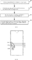
- FIG. 8 illustrates a schematic flowchart of a method for displaying icons, in accordance with an embodiment of present disclosure.
- the method for displaying icons can be applied to the above-mentioned terminal with the special-shaped screen.
- the method for displaying icons may begin at block 810.
- Q first function icons and (P-Q) second function icons are selected from the P function icons.
- Q is a preset positive integer, and P is an integer greater than Q.
- the terminal can determine the value of P as the amount of the function icons according to a configuration of the user.
- the terminal can release setting permissions of the function icons to allow the user to independently select the function icons that need to be displayed in the target region.
- the terminal can also lock a certain number of function icons while release the setting permissions of other function icons.
- the user can determine whether the seven function icons including the function icon 111, the function icon 112, the function icon 113, the function icon 114, the function icon 115, the function icon 116, and the function icon 117 are displayed in the target region.
- the terminal may lock a certain number of first function icons in advance, and release the setting permissions of other first function icons.
- the terminal may lock the function icon 114 to allow the user to determine whether the function icon 111, the function icon 112, the function icon 113, the function icon 115, the function icon 116, and the function icon 117 are used as function icons to be displayed in the target region.
- the terminal can also lock the function icon 111, the function icon 112, the function icon 113, and the function icon 114, and directly determine the above four function icons as function icons to be displayed in the target region. The user only determines whether other icons of other applications are used as function icons. When the user selects 5 function icons as function icons, the number of function icons is 9.
- the terminal determines the first Q function icons as the first function icons, and determines the (Q+1)th to the Pth function icons as the (P-Q) second function icons, according to an order of the P function icons in the terminal.
- the order may be a time sequence in which the activation icons of the applications are determined as the function icon chronologically. For example, a function icon A was determined as a function icon at 21:29:37 on September 3, 2016, while a function icon B was determined as a function icon was 08:47:20 on October 4, 2016, the order of the function icon A is arranged before the function icon B.
- the order may also be an order of times that the function icons have been involved in history, which is ordering from more to less.
- the order may also be the sequence of time intervals between the last times that the function icons was involved and a present moment of the terminal, which is ordering from short to long.
- the Q first function icons are arranged in an arc-shaped arrangement and displayed in the target region.
- the target region is a display region that is adjacent to the edge of the special-shaped screen or surrounds the special-shaped notch region.
- the terminal can arrange Q first function icons in an arc-shaped arrangement and display the Q first function icons in the target region.
- the terminal may arrange Q first function icons in an arc-shaped arrangement and display the Q first function icons at a region attached to the edge of the special-shaped screen.
- the terminal may arrange Q first function icons in an arc-shaped arrangement and display the Q first function icons at a region around the special-shaped notch region.
- K second function icons are displayed in a current user interface, and K is an integer not greater than (P - Q) when an icon display instruction applied to the target region is detected.
- the terminal may display the K second function icons in the current user interface when the terminal detects an icon display instruction applied to the target region, a K is an integer not greater than (P-Q).
- the K second function icons and the Q first function icons are simultaneously displayed in current user interface.
- the K second function icons will replace K first function icons of the Q first function icons and be displayed.
- the method for displaying icons can be applied to the terminal with the special-shaped screen.
- the special-shaped screen includes a special-shaped notch region.
- the terminal selects Q first function icons and (P-Q) second function icons from the P function icons.
- Q is a preset positive integer
- P is an integer greater than Q.
- the Q first function icons are displayed in the target region and arranged in an arc-shaped arrangement.
- the target region is a display region that is adjacent to the edge of the special-shaped screen or surrounds the special-shaped notch region.
- K second function icons are displayed in a current user interface, and K is an integer not greater than (P - Q).
- the terminal can display the originally hidden function icons in the user interface for reposing to the action of the icon display instruction, which enables the user to activate the specified application through the function icon. Operations for to search for the icon of the specified application may be simplified, a speed at which the terminal displays the function icon of the specified application may be increased, an efficiency of activating the specified application is therefore improved.
- the terminal can display the second function icons in a scrolling visual manner, as illustrated in the following embodiment.
- FIG. 9 illustrates a schematic flowchart of a method for displaying icons, in accordance with another embodiment of present disclosure. This method for displaying icons can be applied to any one of the terminals illustrated in FIGs. 1 to 7 . In FIG. 9 , the method for displaying icons may begin at block 810.
- a first arc-shaped display bar is display in a target region.
- the terminal can display the first arc-shaped display bar in the target region.
- the first arc-shaped display bar can be displayed in a region adjacent to an edge of the special-shaped screen, or around the special-shaped notch region of the special-shaped screen.
- the terminal may display the first arc-shaped display bar in a region around the special-shaped notch region.
- the terminal may display the first arc-shaped display bar 110 in the manner illustrated in FIG. 1 and FIG. 2 .
- the terminal may also display the first arc-shaped display bar in a region adjacent to an edge other than the edge in which the special-shaped notch region defined.
- the terminal may also display the first arc-shaped display bar in a region adjacent to the straight-line sub-edge 310.
- the terminal may display the first arc-shaped display bar in a region adjacent to the straight-line sub-edge 311, the straight-line sub-edge 312, or the straight-line sub-edge 313.
- Function icons are displayed in the first arc-shaped display bar.
- the terminal will involve the screen recording service.
- the terminal when the function icon is an activation icon of a screen recording service and the function icon is triggered, the terminal will capture a screenshot of the current user interface.
- the terminal will capture image layers excepting an image layers that is configured to display the first arc-shaped display bar, and superimpose and fuse the images displayed on the captured image layers, and generate a final screenshot image.
- Q first function icons and (P-Q) second function icons are selected from the P function icons.
- the Q first function icons is arranged in an arc-shaped arrangement and displayed in the first arc-shaped display bar.
- the terminal may arrange the Q first function icons in an arc-shaped arrangement, and display the Q first function icons in the first arc-shaped display bar column.
- K second function icons are arranged and display along an arc around the target region when an extended display instruction applied to the target region is detected.
- K is an integer not greater than (P-Q).
- the terminal can replace block 904 by performing operations of sub-block (1) and sub-block (2).
- a second target region is determined when an extended display instruction applied to the first arc-shaped display bar is detected, the second target region is determined based on an edge of the first target region that is adjacent to a center of the screen. The second target region is attached to the first target region.
- the terminal when the terminal detects the expanded display instruction applied to the first arc-shaped display bar, it determines the second target region based on the edge of the first arc-shaped display bar that is adjacent to the center of the screen.
- the second target region may be a second arc-shaped display bar.
- the second arc-shaped display bar may use the edge of the length L1 as a reference to determine the second target region.
- K second function icons are displayed in the second target region.
- the second target region may be a second arc-shaped display bar.
- the terminal can display the K second function icons in the second arc-shaped display bar.
- an order of the K second function icons can be manually adjusted by the user.
- the order of the K second function icons may also be predetermined in advance.
- the second arc-shaped display bar can be display in a different shapes corresponding to different expansion display instructions, which will be described in the following, taking a first display mode, a second display mode, and a third display mode as examples.
- the first display mode in this display mode, the first arc-shaped display bar includes at least two sub-regions. Taking the first arc-shaped display bar 110 illustrated in FIG. 1 as an example, the first arc-shaped display bar 110 of the terminal can be divided into three sub-regions including a first sub-region 110a, a second sub-region 110b, and a third sub-region 110c.
- the second target region is determined based on an edge of a target sub-region adjacent to the center of the screen when the extended display instruction applied to the target sub-region is detected.
- the target sub-region is one of the at least two sub-regions.
- the second target region may be a second arc-shaped display bar.
- the terminal may separately display at least one of the above three sub-regions.
- a displayed sub-region, or a displayed combination of multiple sub-regions is considered as the target sub-regions.
- the terminal may display only one of the first sub-region 110a, the second sub-region 110b, or the third sub-region 110c.
- the terminal may also display two of the first sub-region 110a, the second sub-region 110b, and the third sub-region 110c.
- the terminal may display the two sub-regions adjacent to each other at the same time.
- the terminal may display the first sub-region 110a and the second sub-region 110b at the same time, or display the second sub-region 110b and the third sub-region 110c at the same time.
- FIG. 10 illustrates a schematic view of an operation of displaying a second function icon in the method of FIG. 9 .
- the terminal displays the first sub-region 110a and the second sub-region 110b of the first arc-shaped display bar.
- the terminal detects the expanded display instruction applied to the first arc-shaped display bar, the terminal will display the second arc-shaped display bar 130 in a region attached to an edge of the first arc-shaped display bar that is adjacent to the center of the screen.
- the terminal will display the K second function icons in the second arc-shaped display bar 130 when the second arc-shaped display bar 130 is displayed.
- K equals to 4
- the K second function icons include 4 second function icons including a function icon 131, a function icon 132, a function icon 133, and a function icon 134.
- the display mode 2 in this display mode the first arc-shaped display bar also includes at least two sub-regions.
- the first arc-shaped display bar 110 illustrated in FIG. 1 can be divided into three sub-regions including a first sub-region 110a, a second sub-region 110b, and a third sub-region 110c.
- the terminal will display the first sub-region 110a, the second sub-region 110b, and the third sub-region 110c at a same time.
- the terminal detects the extended display instruction that apply to the first arc-shaped display bar
- the terminal will determine which sub-region the extended display instruction is applied to.
- the second arc-shaped display bar will be displayed next to the sub-region to which the extended display instruction is applied.
- a length of an edge of the second arc-shaped display bar is equal to that of an edge of the said sub-region that id adjacent to the center of the screen.
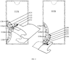
- FIG. 11 illustrates another schematic view of the operation of displaying a second function icon in the method of FIG. 9
- the terminal displays a first arc-shaped display bar 110.
- the first arc-shaped display bar 110 includes a first sub-region 110a, a second sub-region 110b, and a third sub-region 110c.
- the terminal detects the extended display instruction, the terminal will determine the display position and size of the second arc-shaped display bar according to the specific position to where the extended display instruction is applied.
- the terminal when the terminal detects that the extended display instruction (an instruction generated according to a sliding operation into the screen of the user) is applies to the first sub-region 110a, the terminal will display the second arc-shaped display bar 130 basing on the edge of the first sub-region 110a adjacent to the center of the screen.
- the terminal will display K second function icons in the second arc-shaped display bar 130 after the second arc-shaped display bar 130 is displayed.
- K equals to 4
- the K second function icons include 4 second function icons including a function icon 131, a function icon 132, a function icon 133, and a function icon 134.
- the terminal when the terminal detects that the extended display instruction (an instruction generated according to a sliding operation into the screen of the user) applies to the third sub-region 110c, the terminal will display the second arc-shaped display bar 130 basing on the edge of the third sub-region 110c adjacent to the center of the screen.
- the terminal will display K second function icons in the second arc-shaped display bar 130 after the second arc-shaped display bar 130 is displayed.
- K equals to 4
- the K second function icons include 4 second function icons including a function icon 131, a function icon 132, a function icon 133, and a function icon 134.
- the display mode 3 in this display mode, the first arc-shaped display bar also includes at least two sub-regions. Taking the first arc-shaped display bar 110 illustrated in FIG. 1 as an example, the first arc-shaped display bar 110 of the terminal can be divided into three sub-regions including a first sub-region 110a, a second sub-region 110b, and a third sub-region 110c.
- the terminal will display the first sub-region 110a, the second sub-region 110b, and the third sub-region 110c at a same time.
- the terminal detects an expanded display instruction applied to the first arc-shaped display bar, the terminal will directly display the second arc-shaped display bar 130 based on the edge of the entire of the first arc-shaped display bar adjacent to the center of the screen. After the second arc-shaped display bar 130 is displayed, the terminal will display K second function icons in the second arc-shaped display bar.
- FIG. 12 illustrates still another schematic view of the operation of displaying a second function icon in the method of FIG. 9 .
- the terminal displays a first arc-shaped display bar 110.
- the terminal detects the expanded display instruction, the terminal will display the second arc-shaped display bar 130 based on the edge of the first arc-shaped display bar 110 adjacent to the center of the screen.
- the terminal will display K second function icons in the second arc-shaped display bar 130.
- K may equal to 10 in the embodiment illustrated in FIG. 12 .
- the sizes of the second arc-shaped bars in the above-mentioned first display mode, the second display mode, and the third display mode are different from each other, the number K of the second function icons that the terminal can display in the display modes will also be different from each other.
- the first display mode or the second display mode three second function icons is displayed in the second arc-shaped display bar.
- the third display mode seven second function icons can be displayed in the second arc-shaped display bar.
- the method for displaying icons in accordance with this embodiment discloses, by displaying a first arc-shaped display bar in the target region, Q first function icons and (P-Q) second functions icons are selected from the P function icons.
- the Q first function icons are arranged in an arc-shaped arrangement and displayed in the first arc-shaped display bar.
- K second function icons are arranged in an arc-shaped arrangement around the target region and displayed. It can be seen that, in the method, by displaying the second function icons while displaying the first function icons, the function icons configurated by the user may be quickly and completely displayed.
- the embodiment of the present disclosure also provides a method for displaying icons.
- the second function icons may be displayed in a scroll manner, as illustrated in the following embodiments.
- FIG. 13 illustrates a schematic flowchart of a method for displaying icons, in accordance with another embodiment of present disclosure. This method for displaying icons can be applied to the terminal illustrated above. In FIG. 13 , the method for displaying icons may begin at block 1301.
- Q first function icons and (P-Q) second function icons are selected from the P function icons.
- the Q first function icons are arranged and display along an arc in the target region.
- a first arc-shaped display bar is displayed in the target region.
- an edge function icon may be displayed in the first arc-shaped display bar.
- the edge function icon is one of the (P-Q) second function icons.
- the edge function icon is divided into two portions, including a hidden portion and a visible portion, by the edge of the special-shaped screen.
- the visible portion is displayed in the first arc-shaped display bar.
- the hidden portion may be scrolled into the first arc-shaped display bar to be displayed when the terminal detects a sliding operation or a dragging operation from the visible portion toward the center of the screen.
- displaying the edge function icon may remind the user that the first arc-shaped display bar can be scrolled to display other function icons, which may improve the display effect of the function icons and reduces the user's learning cost and operation difficulty.
- FIG. 14 illustrates a schematic view of an operation of displaying icon at an edge in the method of FIG. 13 .
- the function icons are displayed in the first arc-shaped display bar 110.
- the edge function icons 135 are displayed in the first arc-shaped display bar 110.
- the edge function icons 135 are divided into visible portion and the hidden portion, where the visible portion is visible in the first arc-shaped display bar 110.
- block 1303, block 1304, and block 1305 may be performed, or block 1306 may be performed, after the terminal performs block 1301 and block 1302,
- a target sub-region in the first arc-shaped display bar is determined.
- the terminal may determine the target sub-region according to a configuration of the user. In another possible implementation manner, the terminal may also determine the target sub-region according to a default configuration.
- the terminal may determine the third sub-region 110c as the target sub-region according to the configuration of the user.
- the terminal may also determine the first sub-region 110a as the target sub-region according to default configuration.
- M first function icons is displayed in the target sub-region.
- the terminal will display the M first function icons in the target sub-region.
- the target sub-region is one of the at least two sub-regions of the first arc-shaped display bar.
- M is a positive integer not less than K and not greater than Q.
- K first function icons of the M first function icons is replaced with K second function icons of (P-Q) second function icons, and the K second function icons is displayed.
- K is not greater than the smaller one of M and (P-Q).
- the terminal detects the replacement display command applied to the target sub-region, it can determine the value of K according to the replacement instruction.
- the replacement instruction of the terminal may be generated according to a sliding operation. The sliding operation may be along tangent directions of an arc that defined by the first arc-shaped display bar.
- the terminal may determine the value of K according to a sliding displacement of the sliding operation on the touch screen.
- the terminal may determine the value of K according to the corresponding relationship illustrated in Table 1. Table I. sliding displacement (cm) (0,1] (1,2] (2,3] K 1 2 3
- the terminal can select the K first function icons that is to be replaced from the M first function icons according to a direction of the sliding operation after the terminal determines the value of K according to the sliding displacement of the sliding operation on the screen.
- the terminal then generates the replacement instruction correspondingly.
- the terminal may replace the K first function icons with K second function icons of the (P-Q) second function icons according to the replacement instruction.
- the terminal will directly determine K as the smaller one of (P-Q) and M. Subsequently, when the terminal generates the replacement instruction when detects the sliding operation, and the M first function icons are directly replaced by the K second function icons according to the replacement instruction.
- the terminal may select the K second function icons that is used to replace the first function icons according to the direction in which the sliding operation slides on the screen. When the terminal detects that the direction of the sliding operation is in a first direction, the terminal replaces the M first function icons with K1 second function icons. When the terminal detects that the direction of the sliding operation is in a second direction, the terminal replaces the M first function icons with K2 second function icons. The first direction and the second direction are opposite.
- K1 is not greater than the smaller one of (P-Q) and M
- K2 is not greater than the smaller one of (P-Q) and M
- the sum of K1 and K2 is not greater than (P-Q).
- the K1 second function icon and the K2 second function icon are different.
- the terminal may replace the 3 first function icons with 3 (the value of K1) second function icons when the terminal detects a sliding operation in the target sub-region along a downward direction.
- terminal may replace the 3 first function icons with 2 (the value of K2) second function icons when the terminal detects a sliding operation in the target sub-region along an upward direction.
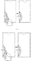
- FIG. 15 illustrates a schematic view of replacing and displaying the second function icon in the method of FIG. 13 .
- the target sub-region is determined as the first sub-region 110a of the first arc-shaped display bar 110.
- the function icon 110a2 and function icon 110a3 in the first sub-region 110a may be scrolled out of the first sub-region 110a and hidden by the terminal when the terminal detects a sliding operation in the first sub-region 110a towards the third sub-region 110c.
- the function icon 110a1 is scrolled to a location in the first sub-region 110a that is adj acent to the second sub-region.
- a function icon 110a4 and a function icon 110a5 are displayed in an upper portion of the first sub-region 110a.
- the embodiment of the present disclosure discloses a solution for scrolling icons indifferent regions.
- K first function icons of the Q first function icons are replaced with K second function icons of the (P-Q) second function icons, when the replacement instruction applied to the first arc-shaped display bar is detected.
- K is a positive integer, and K is not greater than the smaller one of Q and (P-Q).
- the replacement instruction may be an instruction generated according to a sliding operation.
- the sliding operation may be along the tangent directions of the arc defined by the first arc-shaped display bar.
- the terminal may determine the value of K according to the sliding displacement of the sliding operation on the touch screen.
- the terminal may determine the value of K according to a correspondence relationship illustrated in Table 2.
- Table 2 shows the correspondence relationship of the sliding displacement and the value of K.
- Table II sliding displacement (cm) (0,1] (1,2] (2,3] (3,4] (4,5] (5,6] K 1 2 3 4 5 6
- the terminal may select the K first function icons, which is to be replaced by the second function icons, from the Q first function icons according to the direction of the sliding operation, and then generate the replacement instruction accordingly.
- the terminal replaces the K first function icons with the K second function icons according to the replacement instruction.
- FIG. 16 illustrates another schematic view of replacing the first function icons with second function icons in the method of FIG. 13 .
- the terminal the function icons displayed in the first arc-shaped display bar 110 may be scrolled down by the terminal when the terminal detects a sliding operation applied on the first arc-shaped display bar 110.
- FIG. 16 illustrates another schematic view of replacing the first function icons with second function icons in the method of FIG. 13 .
- the function icon H and the function icon I at the bottom are scrolled out of the first arc-shaped display bar 110, and the function icon A and the function icon B are scrolled into the upper portion of the first arc-shaped display bar 110, and displayed in the first arc-shaped display bar 110.
- the method provided in the embodiment of the present disclosure further includes the following operations.
- L locked icons is selected from the Q function icons, and L is an integer not greater than (Q-K).
- K first function icons of the Q first function icons are replaced with K second function icons of the (P-Q) second function icons when the replacement instruction applied to the first arc-shaped display bar is detected.
- K first function icons which is selected from function icons of the Q first function icons excepting the locked icons, are replaced with K second function icons of the (P-Q) second function icons when the replacement instruction applied to the first arc-shaped display bar is detected.
- FIG. 17 illustrates a schematic view of replacing the first function icons with second function icons in a situation in which at least one icon is locked, in the method of FIG. 13 .
- the terminal determines the function icon F as the locked icon from seven displayed first function icons that include the function icon C, the function icon D, the function icon E, the function icon F, the function icon G, the function icon H, and the function icon I.
- the terminal may replace the two first function icons (the function icon H and the function icon I) of the seven first function icons with the function icons A and the function icon B when the terminal detects the replacement instruction applied to the first arc-shaped display bar 110.
- the location of the function icon F remains unchanged, and other icons may be scrolled to the lower portion of the first arc-shaped display bar 110.
- the function icon A and the function icon B may be scrolled into the upper portion of the first arc-shaped display bar 110, and the function icon H and the function icon I may be scrolled out of the lower portion of the first arc-shaped display bar 110.
- the L locked icons is selected from the Q function icons.
- an attribute of each of the function icons of the Q function icons are obtained.
- L of the function icons with attributes indicating that the function icons should remain unchanged are determined as the locked function icons.
- the method provided in the embodiment of the present disclosure further includes the following operations.
- the first arc-shaped display bar is divided into P sub-display-regions when P is an integer not greater than Q.
- the first function icons are displayed in the P sub-display-regions in one-to-one correspondence.
- a central icon is determined when P is an integer not greater than Q.
- the central icon is an icon of an object that provides system customization functions, and belongs to the P function icons.
- the system customization function is a function corresponding to the current foreground application of the terminal.
- the center icon is displayed at the center of the first arc-shaped display bar, and the remaining (P-1) function icons each included in the P function icons are displayed adjacent to the center icon.
- the remaining (P-1) function icons may be symmetrically distributed about the central icon when the value of P is an odd number.
- P/2 function icons of the remaining (P-1) function icons may be displayed on a side of the center icon opposite to gravitational direction, and (P/2-1) icons of the remaining (P-1) function icons may be on a side of the center icon points to gravity.
- the first arc-shaped display bar is displayed in a region attached to the edge of the special-shaped screen or surrounding the special-shaped notch region.
- Q first function icons each included in P function icons and (P-Q) second function icons are selected from the P function icons when there are P function icons.
- the target sub-region is determined in the first arc-shaped display bar.
- M first function icons are displayed in the target sub-region.
- the K first function icons of the M first function icons are replaced with K second function icons selected from the (P-Q) second function icons when a replacement instruction applied to the target sub-region is detected.
- K first function icons of the Q first function icons are replaced with K second function icons selected from the (P-Q) second function icons when a replacement instruction applied to the first arc-shaped display bar is detected.
- the terminal can display the originally hidden function icons in the user interface for responding to the icon display instruction when there are too much function icons arranged in arc-shaped arrangement and displayed at the edge of the terminal screen. Operations for the user to find the specified application are simplified without occupying additional display region. Therefore, the function icons may be quickly displayed, while there is enough space in the user interface to display other contents.
- a device for displaying icons is provided in the following, in accordance with embodiments of the present disclosure.
- the device can be configured to perform the method for displaying function icon according to the embodiments.
- details not disclosed in the embodiments of the device may be illustrated in the embodiments of the method, in accordance with the embodiments of present disclosure.
- FIG. 18 illustrates a structural block diagram of a device for displaying icons, in accordance with an embodiment of the present disclosure.
- the device for displaying icons can be implemented as all or a part of the terminal via software, hardware or a combination of the two.
- the device includes:
- the second icon display module 1830 is configured to arrange the K second function icons in an arc-shaped arrangement around the first target region, and display the K second function icons, when an expanded display instruction applied to the first target region is detected.
- K is an integer not greater than (P-Q).
- the second icon display module 1830 is configured to determine a second target region and display the K second function in the second target region when an extended display instruction applied to the first target region is detected.
- the second target region is determined based on an edge of the first target region that is adjacent to a center of the special-shaped screen.
- the second target region is attached to the first target region.
- the first target region includes at least two sub-regions.
- the second icon display module 1830 is configured to determine the second target region based on an edge of a target sub-region that is adjacent to the center of the screen when the extended display instruction applied to the target sub-region is detected.
- the target sub-region is one of the at least two sub-regions.
- the second icon display module 1830 is configured to replace K first function icons of the Q first function icons with K second function icons of the (P-Q) second function icons when a replacement instruction applied to the first target region is detected.
- K is a positive integer, and K is not greater than the smaller one of Q and (P-Q).
- the first icon display module 1820 is configured to display M first function icons in a target sub-region.
- the target sub-region is one of the at least two sub-regions.
- M is a positive integer not less than K and not greater than Q.
- the second icon display module 1830 is configured to replace K first function icons of the M first function icons with K second function icons of the (P-Q) second function icons when a replacement instruction that applies to the target sub-region is detected.
- the terminal further includes a third display module for displaying an edge function icon.
- the edge function icon is one of the (P-Q) second function icons.
- the edge function icon is divided into a visible portion and a hidden portion. The visible portion is displayed in the first target region.
- the terminal further includes a determining module configured to selected L locked icons from the Q first function icons.
- L is an integer not greater than (Q-K).
- the second icon display module 1830 is configured to replace K first function icons, which is selected from function icons of the Q first function icons excepting the L locked icons, with K second function icons of the (P-Q) second function icons when the replacement instruction applied to the first target region is detected.
- the first target region of the terminal is a first arc-shaped display bar.
- FIG. 19 illustrates a structural block diagram of a terminal, in accordance with an embodiment of the present disclosure.
- the terminal includes a processor 1910, a memory 1920, and a screen module 1930.
- the memory 1920 stores at least one instructions. The instructions are loaded and executed by the processor 1910 to perform the method for displaying icons as described in the above embodiments.
- the embodiment of the present disclosure also provides a computer-readable medium.
- the computer-readable medium stores at least one instruction.
- the at least one instruction is loaded and executed by the processor to perform the method for displaying icons described in each of the above embodiments.
- the embodiments of the present disclosure also provide a computer program product that stores at least one instruction.
- the at least one instruction is loaded and executed by the processor to perform the method for displaying icons described in each of the above embodiments.
- the device for displaying icons provided in the above embodiments executes the method for displaying icons
- the division of the above functional modules is only used as an example for describing.
- the above functions can be allocated to different functions according to different requirements.
- internal structure of the device may be divided into different functional modules to complete all or part of the functions described above.
- the device for displaying icons provided by the above-mentioned embodiments belongs to the same concept as the embodiments of the method for displaying icons. For the specific implementation process, as illustrated in the method embodiments, which will not be repeated here.
- the program can be stored in a computer-readable storage medium.
- the storage medium above-mentioned can be a read-only memory, a magnetic disk or an optical disk, etc.
Landscapes
- Engineering & Computer Science (AREA)
- General Engineering & Computer Science (AREA)
- Theoretical Computer Science (AREA)
- Human Computer Interaction (AREA)
- Physics & Mathematics (AREA)
- General Physics & Mathematics (AREA)
- User Interface Of Digital Computer (AREA)
Abstract
Description
- This application is a continuation of CHINESE Application No.
CN2018105901962, filed on June 08, 2018 - The present disclosure relates to the field of computer technologies, and more particularly, to a method, device, terminal, and storage medium for displaying icons.
- Mobile terminals may implement various functions with different applications.
- In the related art, when a user needs to use a specified application in a mobile terminal, the user may search for an activation icon of the specified application on the desktop of the mobile terminal, and the specified application may be activated when the activation icon is clicked.
- The embodiments of the present disclosure provide a method, device, terminal, and storage medium for displaying icons, as follows:
- In a first aspect, a method for displaying icons is provided. The method is applied to a terminal comprising a special-shaped screen, the special-shaped screen comprising a special-shaped notch region; the method comprising:
- determining Q first function icons and (P-Q) second function icons each included in P function icons, wherein Q is a preset positive integer, and P is an integer greater than Q;
- arranging and displaying the Q first function icons along an arc in a first target region, wherein the first target region is a display region adjacent to an edge of the special-shaped screen or surrounding the special-shaped notch region of the special-shaped screen; and
- displaying K second function icons in a current user interface when an icon display instruction applied to the first target region is detected, where K is an integer not greater than (P-Q).
- In a second aspect, a device for displaying icons are provided. The device is applied to a terminal comprising a special-shaped screen. The special-shaped screen includes a special-shaped notch region; the device includes: an icon determining module, configured to determine Q first function icons and (P-Q) second function icons each included in P function icons; wherein Q is a preset positive integer, and P is an integer greater than Q; a first icon display module, configured to arrange and display the Q first function icons along an arc in a first target region; the first target region being a display region attached to an edge of the special-shaped screen or surrounding the special-shaped notch region; and a second icon display module, configured to display K second function icons in a current user interface when an icon display instruction applied to the first target region being detected, wherein K is an integer not greater than (P-Q).
- In a third aspect, a terminal is provided. The terminal included a processor and a memory. The memory stores and at least one instruction, and the instruction is loaded and executed by the processor to perform the above method for displaying icons.
- In a fourth aspect, a computer-readable storage medium is provided. The storage medium stores at least one instruction, and the instruction is loaded and executed by a processor to perform the above method for displaying icons.
- The above and / or additional aspects and advantages of the present disclosure will become apparent and easily understood from the description of the embodiments in conjunction with the following drawings, in which:
-
FIG. 1 illustrates a schematic view of a display mode of a first arc-shaped display region, in accordance with an embodiment of present disclosure. -
FIG. 2 illustrates a schematic view of another display mode of the first arc-shaped display region, in accordance with an embodiment of present disclosure. -
FIG. 3 to FIG. 7 illustrate schematic views of five possible forms of a special-shaped screen, in accordance with an embodiment of present disclosure. -
FIG. 8 illustrates a schematic flowchart of a method for displaying icons, in accordance with an embodiment of present disclosure. -
FIG. 9 illustrates a schematic flowchart of a method for displaying icons, in accordance with another embodiment of present disclosure. -
FIG. 10 illustrates a schematic view of an operation of displaying a second function icon in the method ofFIG. 9 . -
FIG. 11 illustrates another schematic view of the operation of displaying a second function icon in the method ofFIG. 9 . -
FIG. 12 illustrates still another schematic view of the operation of displaying a second function icon in the method ofFIG. 9 . -
FIG. 13 illustrates a schematic flowchart of a method for displaying icons, in accordance with another embodiment of present disclosure. -
FIG. 14 illustrates a schematic view of an operation of displaying icon at an edge in the method ofFIG. 13 . -
FIG. 15 illustrates a schematic view of replacing the second function icons in the method ofFIG. 13 . -
FIG. 16 illustrates another schematic view of replacing the second function icons in the method ofFIG. 13 . -
FIG. 17 illustrates a schematic view of replacing the second function icons in a situation in which an icon is locked, in the method ofFIG. 13 . -
FIG. 18 illustrates a structural block diagram of a device for displaying icons, in accordance with an embodiment of the present disclosure. -
FIG. 19 illustrates a structural block diagram of a terminal, in accordance with an embodiment of the present disclosure. - In order to facilitate the understanding of the present disclosure, the present disclosure will be described more fully hereinafter with reference to the accompanying drawings. Several embodiments of the present disclosure are presented in the drawings. However, the disclosure may be embodied in many different forms and is not limited to the embodiments described herein. Rather, these embodiments are provided so that this disclosure will be thorough and comprehensive.
- In the technical solution of prior art, when there are a large number of activation icons for activate applications on the desktop of a mobile terminal, an operation for the user to find an activation icon of a specified application is relatively complex. Moreover, when it needs to activate a specified application via the terminal in an urgency, the specified application cannot be quickly activated because of the complex operation.
- When methods provided by the embodiments of the present disclosure is executed, it can be applied to a terminal with a special-shaped screen. The special-shaped screen defines a special-shaped notch region. The terminal is configured to determine Q first function icons and P to Q second function icons among P function icons, where Q is a positive integer in a preset value, and P is an integer greater than Q. The Q first function icons are displayed in an arc arrangement in a target region, and the target region is a display region that is attached to an edge of the special-shaped screen or surrounds the special-shaped notch region. When an icon display instruction applied to the target region is detected, K second function icons are displayed in a current user interface, and K is an integer not greater than (P - Q). Because this method is applied to the terminal with the special-shaped screen, when there are many function icons displayed on the edge of the terminal screen in the arc arrangement, the terminal can display the originally hidden function icons in the user interface for reposing to the action of the icon display instruction, which enables the user to activate the specified application through the function icon. Operations for to search for the icon of the specified application may be simplified, a speed at which the terminal displays the function icon of the specified application may be increased, an efficiency of activating the specified application is therefore improved.
- In order to facilitate the understanding of the solutions illustrated in the embodiments of the present disclosure, several terms appearing in the embodiments of the present disclosure will be introduced below.
- A first target region: refers to a display region that attached to the edge of the special-shaped screen or surrounds the special-shaped notch region in the special-shaped screen. In a possible implementation manner, the first target region may be transparent in a display layer. In another possible implementation manner, the first target region may also be colored in the display layer. Alternatively, the icon display instruction may be applied on the first target region. In a possible implementation manner, the first target region may have first arc-shaped. In another possible implementation manner, the first target region may also be a rectangular region. In other possible implementation manners, the first target region may also be a region in other shapes, which is not limited in the embodiment of the present disclosure. It should be noted that, for the sake of understanding, the following takes the target region having the first arc-shaped as an example.
- A first arc-shaped display bar: refers to a display region having an arc-shaped in the special-shaped screen. The first arc-shaped display bar is configured to display function icons. For example, an icon of application A is displayed in the first arc-shaped display bar, and the icon of application A is a function icon.
- Alternatively, the first arc-shaped bar is an arc-shaped display region surrounding the special-shaped notch region of the special-shaped screen.
- As illustrated in
FIG. 1, FIG. 1 illustrates a schematic view of a display mode of the first arc-shaped bar, in accordance with an embodiment of present disclosure. The first arc-shapeddisplay bar 110 is displayed around the special-shapednotch region 120. Icons of a first application is displayed in the first arc-shapeddisplay bar 110. The icons of the first application may include at least one of afunction icon 111, afunction icon 112, afunction icon 113, afunction icon 114, afunction icon 115, afunction icon 116, and afunction icon 117. - Alternatively, there may be one or at least two first arc-shaped
display bar 110. The number of the first arc-shaped display bar is not limited in the embodiments of the present disclosure. - Alternatively, the first arc-shaped
display bar 110 may be divided into several sub-regions. Each one of the sub-regions can be individually displayed in the user interface in response to a corresponding trigger gesture. The following possible implementations may illustrate the details. - In a possible implementation manner, the first arc-shaped
display bar 110 may be divided into three sub-regions including a first sub-region, a second sub-region, and a third sub-region. Thefunction icon 111, thefunction icon 112, and thefunction icon 113 are displayed in thefirst sub-region 110a. Thefunction icon 114 is displayed in thesecond sub-region 110b. Thefunction icon 115, thefunction icon 116, and thefunction icon 117 are displayed in thethird sub-region 110c. - Alternatively, the first arc-shaped display bar may be triggered when the terminal is in a horizontal display state, or when the terminal is in a vertical display state. For example, as illustrated in
FIG. 1 , the first arc-shaped display bar may be triggered to display on the special-shaped screen when the terminal is in a horizontal display state. As illustrated inFIG. 2, FIG. 2 illustrates a schematic view of another display mode of the first arc-shaped display region, in accordance with an embodiment of present disclosure. InFIG. 2 , the first arc-shaped bar is triggered to display when the terminal is in the vertical display state. - A Function icon: refers to a virtual icon displayed in the first arc-shaped display bar. Alternatively, the function icon may be an activation icon of an in-system application or a third-party application. Alternatively, the function icon may also be an activation icon of a system service or a system process.
- Alternatively, when the function icon is the activation icon of the in-system application, the in-system application may include at least one in-system applications selected from a group of an address book application, a short message application, a phone application, a weather application, a date application, a clock application, a camera application, a gallery application, a browser application, a calculator application, a voice recorder application, a compass application, a flashlight application, a file management application, an application management application, and a setting application.
- Alternatively, when the function icon is the activation icon of the third-party application, the third-party application may include at least one third-party applications selected from a group of a game application, a social chat application, a browser application, a book reading application, a music application, a video application, a live broadcast application, and a short video application, a shopping application, payment and wealth management applications, an image beautification application, a smart device management application, a weather application, a map navigation application, a text editing application, a shared transportation application, a takeaway application, a ticket booking application, a taxi application, an attendance check-in application, a recruitment application, a resource download application, an email application, a news information application, and a scanning code application.
- Alternatively, when the function icon is the activation icon of the system service or the activation icon of the system process, the system service may include at least one system services selected from a group of a wireless LAN switching on/off service, a Bluetooth function switching on/off service, a mobile data function switching on/off service, a ring mode switching service, an automatic rotation service for witching the horizontal and vertical display stated, a flight mode switching on/off service, a location information switching on/off service, a screen recording service, an eye protection mode switching on/off service, an screenshot service, a Do Not Disturb (DND) switching on/off service, a power saving mode switching on/off service, and an Near Field Communication (NFC) switching on/off services.
- A function icon, refers to a specified function icon that is required to be displayed in the first target region or the second target region. The second target region can be implemented as a second arc-shaped display bar. Alternatively, there may be P the function icons, and P is a positive integer.
- A first function icon: refers to a function icon displayed in the first arc-shaped display bar when the first arc-shaped display bar is displayed, for responding to an initially trigger, as an initially display. Alternatively, there may be Q the first function icons, and Q is a positive integer, and P is greater than Q.
- In a possible implementation manner, the initially display may refer to a first time for the first arc-shaped display bar to display when the mobile terminal executes a specified instruction. For example, the initially display may be a first time for the first arc-shaped display bar to display after the mobile terminal is powered on, or it may be the first time for the first arc-shaped display bar to display after the mobile terminal is unlocked.
- In another possible implementation manner, the initial display may be a first time for the first arc-shaped display bar to display in a period predetermined by the mobile terminal. For example, when the period lasts one day, the initial display may be the first time for the first arc-shaped display bar to display in each day. For another example, when the period lasts three days, the initial display may be the first time for the first arc-shaped display bar to display every three days.
- A second function icon: refers to the function icon that is not displayed when the first arc-shaped display bar is in the first display. That is, second function icons may refer to the icons excepting the first function icon among all of the function icons. Alternatively, when the number of function icons is P and the number of first function icons is Q, the number of second function icons is equal to (P-Q).
- In a possible scenario, when the first arc-shaped display bar can display 7 function icons at the same time when expanded, and when there are 15 function icons, the value of P is 15, and the value of Q is 7. P minus Q (P-Q) is 8. That is, the number of the first function icon is 7, and the number of the second function icon is 8.
- An icon display instruction, refers to a computer program instruction that apply to the target region and is configured to instruct the terminal to display K second function icons. Alternatively, the icon display instruction is an instruction generated by the terminal when the terminal receives a specified operation applied by the user. In a possible implementation manner, there may be K second function icons and Q first function icons displaying on the screen simultaneously. In another possible implementation manner, the K first function icons of the Q first function icons may be hidden by the terminal when the K second function icons are displayed.
- An extended display instruction, is one of the icon display instructions, and is configured to instruct the terminal to display K second function icons and Q first function icons in one user interface.
- A replacement instruction: is one of the icon display instructions, and is configured to instruct the terminal to replace the K first function icons of the Q first function icons with K second function icons, and display the K second function icons.
- Exemplarily, the method for displaying icons provided in the embodiments of the present disclosure can be applied to a terminal including a special-shaped screen. It should be noted that this method for displaying icons can also be applied to terminals with a screen such as a full-screen, a foldable screen, a doubled screen, a curved surface screen, or a flexible screen, which is mot limited in embodiments of the present disclosure.
- An outer frame of the terminal, in accordance with an embodiment of present disclosure, may include a first edge and a second edge. The special-shaped screen includes a concave sub-edge and three straight sub-edges. The concave sub-edge is attached to the first edge. Two of the three straight sub-edges, which is adjacent to the concave sub-edge, are attached to the two second edges respectively. A length of the first edge is not larger than that of the second edge. The concave sub-edge and the outer frame of the terminal cooperatively define a special-shaped notch region. The special-shaped notch region is configured to accommodate a sensor in a front case of the terminal. The concave sub-edge can include a concave portion defined by a poly line or a curve line. For example, as illustrated in
FIG. 3 to FIG. 7, FIG. 3 to FIG. 7 illustrate schematic views of five possible forms of a special-shaped screen. In the various forms illustrated above, the straight sub-edge 310 may be a rounded straight-line segment or a straight-line segment. Theconcave sub-edge 320 can have any one of the forms in the five possible forms as illustrated inFIGs. 3 to 7 . InFIG. 3 , theconcave sub-edge 320 is an edge with a semicircular notch. InFIG. 4 , theconcave sub-edge 320 is an edge with an arc-shaped notch. InFIG. 5 , theconcave sub-edge 320 is an edge with a rectangular notch. InFIG. 6 , theconcave sub-edge 320 is an edge with a rounded rectangular notch. InFIG. 7 , theconcave sub-edge 320 is an edge with a triangular notch. It should be noted that the specific shape of the special-shaped screen is not limited in the embodiments of the present disclosure. The above five forms are part of the appearance of the special-shaped screen of terminal to which the solution of the present disclosure can be applied. - Alternatively, taking
FIG. 3 as an example, the first edge, to which the concave sub-edge attached, can be represented asedge 321, and the two second edge, to which the two straight sub-edges adjacent to the concave sub-edge are respectively attached to, can be labeled as 311 and 312, respectively. Alternatively, another edge parallel to the first edge may be represented as athird edge 313. - Alternatively, the terminal may be selected from a group of a mobile phone, a tablet computer, a smart glass, a smart watch, a digital camera, an MP4 playback terminal, an MP5 playback terminal, a learning machine, a dot reading machine, an electronic paper book, an electronic dictionary, a virtual reality (VR) play terminal, or an augmented reality (AR) play terminal, etc.
- As illustrated in
FIG. 8, FIG. 8 illustrates a schematic flowchart of a method for displaying icons, in accordance with an embodiment of present disclosure. The method for displaying icons can be applied to the above-mentioned terminal with the special-shaped screen. InFIG. 8 , the method for displaying icons may begin atblock 810. - At
block 810, Q first function icons and (P-Q) second function icons are selected from the P function icons. Q is a preset positive integer, and P is an integer greater than Q. - In the embodiments of the present disclosure, in a possible implementation manner, the terminal can determine the value of P as the amount of the function icons according to a configuration of the user.
- In another possible implementation manner, the terminal can release setting permissions of the function icons to allow the user to independently select the function icons that need to be displayed in the target region.
- In another possible implementation manner, the terminal can also lock a certain number of function icons while release the setting permissions of other function icons.
- For example, in a possible implementation manner, take the display manner illustrated in
FIG. 1 as an example, the user can determine whether the seven function icons including thefunction icon 111, thefunction icon 112, thefunction icon 113, thefunction icon 114, thefunction icon 115, thefunction icon 116, and thefunction icon 117 are displayed in the target region. - In another possible implementation manner, the terminal may lock a certain number of first function icons in advance, and release the setting permissions of other first function icons. For example, the terminal may lock the
function icon 114 to allow the user to determine whether thefunction icon 111, thefunction icon 112, thefunction icon 113, thefunction icon 115, thefunction icon 116, and thefunction icon 117 are used as function icons to be displayed in the target region. For another example, the terminal can also lock thefunction icon 111, thefunction icon 112, thefunction icon 113, and thefunction icon 114, and directly determine the above four function icons as function icons to be displayed in the target region. The user only determines whether other icons of other applications are used as function icons. When the user selects 5 function icons as function icons, the number of function icons is 9. - In a possible implementation manner, the terminal determines the first Q function icons as the first function icons, and determines the (Q+1)th to the Pth function icons as the (P-Q) second function icons, according to an order of the P function icons in the terminal.
- Alternatively, the order may be a time sequence in which the activation icons of the applications are determined as the function icon chronologically. For example, a function icon A was determined as a function icon at 21:29:37 on September 3, 2016, while a function icon B was determined as a function icon was 08:47:20 on October 4, 2016, the order of the function icon A is arranged before the function icon B.
- Alternatively, the order may also be an order of times that the function icons have been involved in history, which is ordering from more to less.
- Alternatively, the order may also be the sequence of time intervals between the last times that the function icons was involved and a present moment of the terminal, which is ordering from short to long.
- At
block 820, the Q first function icons are arranged in an arc-shaped arrangement and displayed in the target region. The target region is a display region that is adjacent to the edge of the special-shaped screen or surrounds the special-shaped notch region. - In the embodiments of the present disclosure, the terminal can arrange Q first function icons in an arc-shaped arrangement and display the Q first function icons in the target region. In a possible manner, the terminal may arrange Q first function icons in an arc-shaped arrangement and display the Q first function icons at a region attached to the edge of the special-shaped screen. In another possible manner, the terminal may arrange Q first function icons in an arc-shaped arrangement and display the Q first function icons at a region around the special-shaped notch region.
- At
block 830, K second function icons are displayed in a current user interface, and K is an integer not greater than (P - Q) when an icon display instruction applied to the target region is detected. - In the embodiments of the present disclosure, the terminal may display the K second function icons in the current user interface when the terminal detects an icon display instruction applied to the target region, a K is an integer not greater than (P-Q).
- In a possible implementation manner, the K second function icons and the Q first function icons are simultaneously displayed in current user interface.
- In another possible implementation manner, the K second function icons will replace K first function icons of the Q first function icons and be displayed.
- In summary, the method for displaying icons provided in this embodiment can be applied to the terminal with the special-shaped screen. The special-shaped screen includes a special-shaped notch region. The terminal selects Q first function icons and (P-Q) second function icons from the P function icons. Q is a preset positive integer, and P is an integer greater than Q. The Q first function icons are displayed in the target region and arranged in an arc-shaped arrangement. The target region is a display region that is adjacent to the edge of the special-shaped screen or surrounds the special-shaped notch region. When an icon display instruction applied to the target region is detected, K second function icons are displayed in a current user interface, and K is an integer not greater than (P - Q).
- Because this method is applied to the terminal with the special-shaped screen, when there are many function icons displayed on the edge of the terminal screen in the arc arrangement, the terminal can display the originally hidden function icons in the user interface for reposing to the action of the icon display instruction, which enables the user to activate the specified application through the function icon. Operations for to search for the icon of the specified application may be simplified, a speed at which the terminal displays the function icon of the specified application may be increased, an efficiency of activating the specified application is therefore improved.
- Based on the previous embodiment, the terminal can display the second function icons in a scrolling visual manner, as illustrated in the following embodiment.
- As illustrated in
FIG. 9, FIG. 9 illustrates a schematic flowchart of a method for displaying icons, in accordance with another embodiment of present disclosure. This method for displaying icons can be applied to any one of the terminals illustrated inFIGs. 1 to 7 . InFIG. 9 , the method for displaying icons may begin atblock 810. - At
block 901, a first arc-shaped display bar is display in a target region. - In the embodiment of the present disclosure, the terminal can display the first arc-shaped display bar in the target region. The first arc-shaped display bar can be displayed in a region adjacent to an edge of the special-shaped screen, or around the special-shaped notch region of the special-shaped screen.
- In the embodiments of the present disclosure, the terminal may display the first arc-shaped display bar in a region around the special-shaped notch region. In a possible implementation manner, for example, the terminal may display the first arc-shaped
display bar 110 in the manner illustrated inFIG. 1 and FIG. 2 . In another possible implementation manner, the terminal may also display the first arc-shaped display bar in a region adjacent to an edge other than the edge in which the special-shaped notch region defined. TakingFIG. 3 as an example, the terminal may also display the first arc-shaped display bar in a region adjacent to the straight-line sub-edge 310. For example, the terminal may display the first arc-shaped display bar in a region adjacent to the straight-line sub-edge 311, the straight-line sub-edge 312, or the straight-line sub-edge 313. Function icons are displayed in the first arc-shaped display bar. - Alternatively, when the function icon is an activation icon of a screen recording service and the function icon is triggered, the terminal will involve the screen recording service.
- Alternatively, when the function icon is an activation icon of a screen recording service and the function icon is triggered, the terminal will capture a screenshot of the current user interface. In a possible implementation manner, the terminal will capture image layers excepting an image layers that is configured to display the first arc-shaped display bar, and superimpose and fuse the images displayed on the captured image layers, and generate a final screenshot image.
- At
block 902, Q first function icons and (P-Q) second function icons are selected from the P function icons. - It should be noted that the operation in
block 902 is identical to the operation inblock 810, which will not be repeated here. - At
block 903, the Q first function icons is arranged in an arc-shaped arrangement and displayed in the first arc-shaped display bar. - In the embodiment of the present disclosure, the terminal may arrange the Q first function icons in an arc-shaped arrangement, and display the Q first function icons in the first arc-shaped display bar column.
- In at
block 904, K second function icons are arranged and display along an arc around the target region when an extended display instruction applied to the target region is detected. - In the embodiment of the present disclosure, K is an integer not greater than (P-Q).
- Alternatively, as an alternative implementation of
block 904, the terminal can replace block 904 by performing operations of sub-block (1) and sub-block (2). - At sub-block (1), a second target region is determined when an extended display instruction applied to the first arc-shaped display bar is detected, the second target region is determined based on an edge of the first target region that is adjacent to a center of the screen. The second target region is attached to the first target region.
- In the embodiment of the present disclosure, when the terminal detects the expanded display instruction applied to the first arc-shaped display bar, it determines the second target region based on the edge of the first arc-shaped display bar that is adjacent to the center of the screen. The second target region may be a second arc-shaped display bar.
- For example, when a length of an edge of the first arc-shaped display bar is L1, the second arc-shaped display bar may use the edge of the length L1 as a reference to determine the second target region.
- At sub-block (2), K second function icons are displayed in the second target region.
- In the embodiment of the present disclosure, the second target region may be a second arc-shaped display bar. The terminal can display the K second function icons in the second arc-shaped display bar. Alternatively, an order of the K second function icons can be manually adjusted by the user. Alternatively, the order of the K second function icons may also be predetermined in advance.
- It should be noted that the second arc-shaped display bar can be display in a different shapes corresponding to different expansion display instructions, which will be described in the following, taking a first display mode, a second display mode, and a third display mode as examples.
- The first display mode: in this display mode, the first arc-shaped display bar includes at least two sub-regions. Taking the first arc-shaped
display bar 110 illustrated inFIG. 1 as an example, the first arc-shapeddisplay bar 110 of the terminal can be divided into three sub-regions including afirst sub-region 110a, asecond sub-region 110b, and athird sub-region 110c. - In this display mode, the second target region is determined based on an edge of a target sub-region adjacent to the center of the screen when the extended display instruction applied to the target sub-region is detected. The target sub-region is one of the at least two sub-regions. Alternatively, the second target region may be a second arc-shaped display bar.
- Alternatively, the terminal may separately display at least one of the above three sub-regions. A displayed sub-region, or a displayed combination of multiple sub-regions is considered as the target sub-regions. For example, the terminal may display only one of the
first sub-region 110a, thesecond sub-region 110b, or thethird sub-region 110c. For another example, the terminal may also display two of thefirst sub-region 110a, thesecond sub-region 110b, and thethird sub-region 110c. - In a possible application manner, in order to enhance the user's visual effect, the terminal may display the two sub-regions adjacent to each other at the same time. For example, the terminal may display the
first sub-region 110a and thesecond sub-region 110b at the same time, or display thesecond sub-region 110b and thethird sub-region 110c at the same time. - As illustrated in
FIG. 10, FIG. 10 illustrates a schematic view of an operation of displaying a second function icon in the method ofFIG. 9 . InFIG. 10 , the terminal displays thefirst sub-region 110a and thesecond sub-region 110b of the first arc-shaped display bar. When the terminal detects the expanded display instruction applied to the first arc-shaped display bar, the terminal will display the second arc-shapeddisplay bar 130 in a region attached to an edge of the first arc-shaped display bar that is adjacent to the center of the screen. The terminal will display the K second function icons in the second arc-shapeddisplay bar 130 when the second arc-shapeddisplay bar 130 is displayed. InFIG. 10 , K equals to 4, and the K second function icons include 4 second function icons including afunction icon 131, afunction icon 132, afunction icon 133, and afunction icon 134. - The display mode 2, in this display mode, the first arc-shaped display bar also includes at least two sub-regions. Taking the first arc-shaped
display bar 110 illustrated inFIG. 1 as an example, the first arc-shapeddisplay bar 110 of the terminal can be divided into three sub-regions including afirst sub-region 110a, asecond sub-region 110b, and athird sub-region 110c. - In this display mode, the terminal will display the
first sub-region 110a, thesecond sub-region 110b, and thethird sub-region 110c at a same time. When the terminal detects the extended display instruction that apply to the first arc-shaped display bar, the terminal will determine which sub-region the extended display instruction is applied to. After determining the sub-region to which the extended display instruction is applied, the second arc-shaped display bar will be displayed next to the sub-region to which the extended display instruction is applied. A length of an edge of the second arc-shaped display bar is equal to that of an edge of the said sub-region that id adjacent to the center of the screen. - As illustrated in
FIG. 11, FIG. 11 illustrates another schematic view of the operation of displaying a second function icon in the method ofFIG. 9 InFIG. 11 , the terminal displays a first arc-shapeddisplay bar 110. The first arc-shapeddisplay bar 110 includes afirst sub-region 110a, asecond sub-region 110b, and athird sub-region 110c. When the terminal detects the extended display instruction, the terminal will determine the display position and size of the second arc-shaped display bar according to the specific position to where the extended display instruction is applied. - For example, in the
user interface 11A, when the terminal detects that the extended display instruction (an instruction generated according to a sliding operation into the screen of the user) is applies to thefirst sub-region 110a, the terminal will display the second arc-shapeddisplay bar 130 basing on the edge of thefirst sub-region 110a adjacent to the center of the screen. The terminal will display K second function icons in the second arc-shapeddisplay bar 130 after the second arc-shapeddisplay bar 130 is displayed. In theuser interface 11A, K equals to 4, the K second function icons include 4 second function icons including afunction icon 131, afunction icon 132, afunction icon 133, and afunction icon 134. - For another example, in the
user interface 11B, when the terminal detects that the extended display instruction (an instruction generated according to a sliding operation into the screen of the user) applies to thethird sub-region 110c, the terminal will display the second arc-shapeddisplay bar 130 basing on the edge of thethird sub-region 110c adjacent to the center of the screen. The terminal will display K second function icons in the second arc-shapeddisplay bar 130 after the second arc-shapeddisplay bar 130 is displayed. In theuser interface 11B, K equals to 4, the K second function icons include 4 second function icons including afunction icon 131, afunction icon 132, afunction icon 133, and afunction icon 134. - The display mode 3: in this display mode, the first arc-shaped display bar also includes at least two sub-regions. Taking the first arc-shaped
display bar 110 illustrated inFIG. 1 as an example, the first arc-shapeddisplay bar 110 of the terminal can be divided into three sub-regions including afirst sub-region 110a, asecond sub-region 110b, and athird sub-region 110c. - In this display mode, the terminal will display the
first sub-region 110a, thesecond sub-region 110b, and thethird sub-region 110c at a same time. When the terminal detects an expanded display instruction applied to the first arc-shaped display bar, the terminal will directly display the second arc-shapeddisplay bar 130 based on the edge of the entire of the first arc-shaped display bar adjacent to the center of the screen. After the second arc-shapeddisplay bar 130 is displayed, the terminal will display K second function icons in the second arc-shaped display bar. - As illustrated in
FIG. 12, FIG. 12 illustrates still another schematic view of the operation of displaying a second function icon in the method ofFIG. 9 . InFIG. 12 , the terminal displays a first arc-shapeddisplay bar 110. When the terminal detects the expanded display instruction, the terminal will display the second arc-shapeddisplay bar 130 based on the edge of the first arc-shapeddisplay bar 110 adjacent to the center of the screen. After the second arc-shapeddisplay bar 130 is displayed, the terminal will display K second function icons in the second arc-shapeddisplay bar 130. Alternatively, K may equal to 10 in the embodiment illustrated inFIG. 12 . - It should be noted that the sizes of the second arc-shaped bars in the above-mentioned first display mode, the second display mode, and the third display mode are different from each other, the number K of the second function icons that the terminal can display in the display modes will also be different from each other. For example, in the first display mode or the second display mode, three second function icons is displayed in the second arc-shaped display bar. In the third display mode, seven second function icons can be displayed in the second arc-shaped display bar.
- In summary, in the method for displaying icons, in accordance with this embodiment discloses, by displaying a first arc-shaped display bar in the target region, Q first function icons and (P-Q) second functions icons are selected from the P function icons. The Q first function icons are arranged in an arc-shaped arrangement and displayed in the first arc-shaped display bar. When the extended display instruction applied to the target region is detected, K second function icons are arranged in an arc-shaped arrangement around the target region and displayed. It can be seen that, in the method, by displaying the second function icons while displaying the first function icons, the function icons configurated by the user may be quickly and completely displayed. When the user needs to involve the function icons in the first arc-shaped display bar and the function icons in the second arc-shaped display bar in sequence in a short time, operations for the user to switch different interfaces are simplified, and an efficiency of the user using the first function icons and the second function icons at the same time is improved.
- Based on the above embodiments, the embodiment of the present disclosure also provides a method for displaying icons. In the method, the second function icons may be displayed in a scroll manner, as illustrated in the following embodiments.
- As illustrated in
FIG. 13, FIG. 13 illustrates a schematic flowchart of a method for displaying icons, in accordance with another embodiment of present disclosure. This method for displaying icons can be applied to the terminal illustrated above. InFIG. 13 , the method for displaying icons may begin atblock 1301. - At
block 1301, Q first function icons and (P-Q) second function icons are selected from the P function icons. - At
block 1302, the Q first function icons are arranged and display along an arc in the target region. - It should be noted that the operation in
block 1301 is identical to the operation inblock 810, and operation inblock 1303 is identical to the operation inblock 820, which will not be repeated here. - In a possible implementation manner, a first arc-shaped display bar is displayed in the target region. When the terminal displays the first arc-shaped display bar attached to the edge of the special-shaped screen or around the special-shaped notch region, an edge function icon may be displayed in the first arc-shaped display bar. The edge function icon is one of the (P-Q) second function icons. The edge function icon is divided into two portions, including a hidden portion and a visible portion, by the edge of the special-shaped screen. The visible portion is displayed in the first arc-shaped display bar. Alternatively, the hidden portion may be scrolled into the first arc-shaped display bar to be displayed when the terminal detects a sliding operation or a dragging operation from the visible portion toward the center of the screen.
- It can be seen that displaying the edge function icon may remind the user that the first arc-shaped display bar can be scrolled to display other function icons, which may improve the display effect of the function icons and reduces the user's learning cost and operation difficulty.
- As illustrated in
FIG. 14, FIG. 14 illustrates a schematic view of an operation of displaying icon at an edge in the method ofFIG. 13 . InFIG. 14 , the function icons are displayed in the first arc-shapeddisplay bar 110. Theedge function icons 135 are displayed in the first arc-shapeddisplay bar 110. Theedge function icons 135 are divided into visible portion and the hidden portion, where the visible portion is visible in the first arc-shapeddisplay bar 110. - In the embodiments of the present disclosure,
block 1303,block 1304, and block 1305 may be performed, or block 1306 may be performed, after the terminal performsblock 1301 andblock 1302, - At
block 1303, a target sub-region in the first arc-shaped display bar is determined. - In the embodiment of the present disclosure, the terminal may determine the target sub-region according to a configuration of the user. In another possible implementation manner, the terminal may also determine the target sub-region according to a default configuration.
- Taking the first arc-shaped
display bar 110 illustrated inFIG. 1 as an example, the terminal may determine thethird sub-region 110c as the target sub-region according to the configuration of the user. The terminal may also determine thefirst sub-region 110a as the target sub-region according to default configuration. - At
block 1304, M first function icons is displayed in the target sub-region. - In this embodiment of the application, the terminal will display the M first function icons in the target sub-region. The target sub-region is one of the at least two sub-regions of the first arc-shaped display bar. M is a positive integer not less than K and not greater than Q.
- At
block 1305, when a replacement instruction applied to the target sub-region is detected, K first function icons of the M first function icons is replaced with K second function icons of (P-Q) second function icons, and the K second function icons is displayed. - In the embodiment of the present disclosure, K is not greater than the smaller one of M and (P-Q). When the terminal detects the replacement display command applied to the target sub-region, it can determine the value of K according to the replacement instruction. In a possible implementation manner, the replacement instruction of the terminal may be generated according to a sliding operation. The sliding operation may be along tangent directions of an arc that defined by the first arc-shaped display bar. Alternatively, the terminal may determine the value of K according to a sliding displacement of the sliding operation on the touch screen. Exemplarily, the terminal may determine the value of K according to the corresponding relationship illustrated in Table 1.
Table I. sliding displacement (cm) (0,1] (1,2] (2,3] K 1 2 3 - The terminal can select the K first function icons that is to be replaced from the M first function icons according to a direction of the sliding operation after the terminal determines the value of K according to the sliding displacement of the sliding operation on the screen. The terminal then generates the replacement instruction correspondingly. The terminal may replace the K first function icons with K second function icons of the (P-Q) second function icons according to the replacement instruction.
- In another possible implementation manner, the terminal will directly determine K as the smaller one of (P-Q) and M. Subsequently, when the terminal generates the replacement instruction when detects the sliding operation, and the M first function icons are directly replaced by the K second function icons according to the replacement instruction. Alternatively, the terminal may select the K second function icons that is used to replace the first function icons according to the direction in which the sliding operation slides on the screen. When the terminal detects that the direction of the sliding operation is in a first direction, the terminal replaces the M first function icons with K1 second function icons. When the terminal detects that the direction of the sliding operation is in a second direction, the terminal replaces the M first function icons with K2 second function icons. The first direction and the second direction are opposite. K1 is not greater than the smaller one of (P-Q) and M, and K2 is not greater than the smaller one of (P-Q) and M, and the sum of K1 and K2 is not greater than (P-Q). The K1 second function icon and the K2 second function icon are different.
- For example, there are 3 (the value of M) first function icons and 5 (the value of (P-Q)) second function icons displayed in the target sub-region. The terminal may replace the 3 first function icons with 3 (the value of K1) second function icons when the terminal detects a sliding operation in the target sub-region along a downward direction. Alternatively, terminal may replace the 3 first function icons with 2 (the value of K2) second function icons when the terminal detects a sliding operation in the target sub-region along an upward direction.
- As illustrated in
FIG. 15, FIG. 15 illustrates a schematic view of replacing and displaying the second function icon in the method ofFIG. 13 . InFIG. 15 , the target sub-region is determined as thefirst sub-region 110a of the first arc-shapeddisplay bar 110. The function icon 110a2 and function icon 110a3 in thefirst sub-region 110a may be scrolled out of thefirst sub-region 110a and hidden by the terminal when the terminal detects a sliding operation in thefirst sub-region 110a towards thethird sub-region 110c. The function icon 110a1 is scrolled to a location in thefirst sub-region 110a that is adj acent to the second sub-region. A function icon 110a4 and a function icon 110a5 are displayed in an upper portion of thefirst sub-region 110a. - It can be seen that the embodiment of the present disclosure discloses a solution for scrolling icons indifferent regions.
- At
block 1306, K first function icons of the Q first function icons are replaced with K second function icons of the (P-Q) second function icons, when the replacement instruction applied to the first arc-shaped display bar is detected. - In the embodiment of the present disclosure, K is a positive integer, and K is not greater than the smaller one of Q and (P-Q). The replacement instruction may be an instruction generated according to a sliding operation. The sliding operation may be along the tangent directions of the arc defined by the first arc-shaped display bar.
- Alternatively, the terminal may determine the value of K according to the sliding displacement of the sliding operation on the touch screen. Exemplarily, the terminal may determine the value of K according to a correspondence relationship illustrated in Table 2. Table 2 shows the correspondence relationship of the sliding displacement and the value of K.
Table II sliding displacement (cm) (0,1] (1,2] (2,3] (3,4] (4,5] (5,6] K 1 2 3 4 5 6 - After the terminal determines the value of K according to the sliding displacement of the sliding operation on the screen, the terminal may select the K first function icons, which is to be replaced by the second function icons, from the Q first function icons according to the direction of the sliding operation, and then generate the replacement instruction accordingly. The terminal replaces the K first function icons with the K second function icons according to the replacement instruction. For example, as illustrated in
FIG. 16, FIG. 16 illustrates another schematic view of replacing the first function icons with second function icons in the method ofFIG. 13 . InFIG. 16 , the terminal the function icons displayed in the first arc-shapeddisplay bar 110 may be scrolled down by the terminal when the terminal detects a sliding operation applied on the first arc-shapeddisplay bar 110. InFIG. 16 , the function icon H and the function icon I at the bottom are scrolled out of the first arc-shapeddisplay bar 110, and the function icon A and the function icon B are scrolled into the upper portion of the first arc-shapeddisplay bar 110, and displayed in the first arc-shapeddisplay bar 110. - It should be noted that, in a possible implementation manner, the method provided in the embodiment of the present disclosure further includes the following operations. In the method, L locked icons is selected from the Q function icons, and L is an integer not greater than (Q-K). K first function icons of the Q first function icons are replaced with K second function icons of the (P-Q) second function icons when the replacement instruction applied to the first arc-shaped display bar is detected. In particular, K first function icons, which is selected from function icons of the Q first function icons excepting the locked icons, are replaced with K second function icons of the (P-Q) second function icons when the replacement instruction applied to the first arc-shaped display bar is detected.
- In a possible implementation manner, as illustrated in
FIG. 17 , illustrates a schematic view of replacing the first function icons with second function icons in a situation in which at least one icon is locked, in the method ofFIG. 13 . InFIG. 17 , the terminal determines the function icon F as the locked icon from seven displayed first function icons that include the function icon C, the function icon D, the function icon E, the function icon F, the function icon G, the function icon H, and the function icon I. The terminal may replace the two first function icons (the function icon H and the function icon I) of the seven first function icons with the function icons A and the function icon B when the terminal detects the replacement instruction applied to the first arc-shapeddisplay bar 110. In particular, in the function icons of the first arc-shapeddisplay bar 110, the location of the function icon F remains unchanged, and other icons may be scrolled to the lower portion of the first arc-shapeddisplay bar 110. The function icon A and the function icon B may be scrolled into the upper portion of the first arc-shapeddisplay bar 110, and the function icon H and the function icon I may be scrolled out of the lower portion of the first arc-shapeddisplay bar 110. - In another possible implementation manner, the L locked icons is selected from the Q function icons. In particular, an attribute of each of the function icons of the Q function icons are obtained. L of the function icons with attributes indicating that the function icons should remain unchanged are determined as the locked function icons.
- In another possible implementation manner, the method provided in the embodiment of the present disclosure further includes the following operations. In the method, the first arc-shaped display bar is divided into P sub-display-regions when P is an integer not greater than Q. The first function icons are displayed in the P sub-display-regions in one-to-one correspondence.
- In another possible implementation manner, a central icon is determined when P is an integer not greater than Q. The central icon is an icon of an object that provides system customization functions, and belongs to the P function icons. The system customization function is a function corresponding to the current foreground application of the terminal. The center icon is displayed at the center of the first arc-shaped display bar, and the remaining (P-1) function icons each included in the P function icons are displayed adjacent to the center icon.
- It should be noted that, the remaining (P-1) function icons may be symmetrically distributed about the central icon when the value of P is an odd number. When the value of P is an even number, P/2 function icons of the remaining (P-1) function icons may be displayed on a side of the center icon opposite to gravitational direction, and (P/2-1) icons of the remaining (P-1) function icons may be on a side of the center icon points to gravity.
- In summary, in the method for displaying icons according to the illustrated embodiment, the first arc-shaped display bar is displayed in a region attached to the edge of the special-shaped screen or surrounding the special-shaped notch region. Q first function icons each included in P function icons and (P-Q) second function icons are selected from the P function icons when there are P function icons. The target sub-region is determined in the first arc-shaped display bar. M first function icons are displayed in the target sub-region. The K first function icons of the M first function icons are replaced with K second function icons selected from the (P-Q) second function icons when a replacement instruction applied to the target sub-region is detected. Alternatively, K first function icons of the Q first function icons are replaced with K second function icons selected from the (P-Q) second function icons when a replacement instruction applied to the first arc-shaped display bar is detected. Because the method may be applied to the terminal with the special-shaped screen, the terminal can display the originally hidden function icons in the user interface for responding to the icon display instruction when there are too much function icons arranged in arc-shaped arrangement and displayed at the edge of the terminal screen. Operations for the user to find the specified application are simplified without occupying additional display region. Therefore, the function icons may be quickly displayed, while there is enough space in the user interface to display other contents.
- A device for displaying icons is provided in the following, in accordance with embodiments of the present disclosure. The device can be configured to perform the method for displaying function icon according to the embodiments. For details not disclosed in the embodiments of the device, may be illustrated in the embodiments of the method, in accordance with the embodiments of present disclosure.
- As illustrated in
FIG. 18, FIG. 18 illustrates a structural block diagram of a device for displaying icons, in accordance with an embodiment of the present disclosure. The device for displaying icons can be implemented as all or a part of the terminal via software, hardware or a combination of the two. The device includes: - an
icon determining module 1810, configured to determine Q first function icons and (P-Q) second function icons each included in P function icons, Q being a preset positive integer, and P being an integer greater than Q; - a first
icon display module 1820, configured to arrange the Q first function icons in an arc-shaped arrangement and display the Q first function icons in a first target region; the first target region being a display region attached to an edge of the special-shaped screen or surrounding the special-shaped notch region; and - a second
icon display module 1830, configured to display K second function icons in a current user interface when an icon display instruction applied to the first target region being detected, and K being an integer not greater than (P-Q). - In an alternative embodiment, the second
icon display module 1830 is configured to arrange the K second function icons in an arc-shaped arrangement around the first target region, and display the K second function icons, when an expanded display instruction applied to the first target region is detected. K is an integer not greater than (P-Q). - In an alternative embodiment, the second
icon display module 1830 is configured to determine a second target region and display the K second function in the second target region when an extended display instruction applied to the first target region is detected. The second target region is determined based on an edge of the first target region that is adjacent to a center of the special-shaped screen. The second target region is attached to the first target region. - In an alternative embodiment, the first target region includes at least two sub-regions. The second
icon display module 1830 is configured to determine the second target region based on an edge of a target sub-region that is adjacent to the center of the screen when the extended display instruction applied to the target sub-region is detected. The target sub-region is one of the at least two sub-regions. - In an alternative embodiment, the second
icon display module 1830 is configured to replace K first function icons of the Q first function icons with K second function icons of the (P-Q) second function icons when a replacement instruction applied to the first target region is detected. K is a positive integer, and K is not greater than the smaller one of Q and (P-Q). - In an alternative embodiment, the first
icon display module 1820 is configured to display M first function icons in a target sub-region. The target sub-region is one of the at least two sub-regions. M is a positive integer not less than K and not greater than Q. The secondicon display module 1830 is configured to replace K first function icons of the M first function icons with K second function icons of the (P-Q) second function icons when a replacement instruction that applies to the target sub-region is detected. - In an alternative embodiment, the terminal further includes a third display module for displaying an edge function icon. The edge function icon is one of the (P-Q) second function icons. The edge function icon is divided into a visible portion and a hidden portion. The visible portion is displayed in the first target region.
- In an alternative embodiment, the terminal further includes a determining module configured to selected L locked icons from the Q first function icons. L is an integer not greater than (Q-K). The second
icon display module 1830 is configured to replace K first function icons, which is selected from function icons of the Q first function icons excepting the L locked icons, with K second function icons of the (P-Q) second function icons when the replacement instruction applied to the first target region is detected. - In an alternative embodiment, the first target region of the terminal is a first arc-shaped display bar.
- As illustrated in
FIG. 19, FIG. 19 illustrates a structural block diagram of a terminal, in accordance with an embodiment of the present disclosure. As illustrated inFIG. 19 , the terminal includes aprocessor 1910, amemory 1920, and ascreen module 1930. Thememory 1920 stores at least one instructions. The instructions are loaded and executed by theprocessor 1910 to perform the method for displaying icons as described in the above embodiments. - The embodiment of the present disclosure also provides a computer-readable medium. The computer-readable medium stores at least one instruction. The at least one instruction is loaded and executed by the processor to perform the method for displaying icons described in each of the above embodiments.
- The embodiments of the present disclosure also provide a computer program product that stores at least one instruction. The at least one instruction is loaded and executed by the processor to perform the method for displaying icons described in each of the above embodiments.
- It should be noted that when the device for displaying icons provided in the above embodiments executes the method for displaying icons, the division of the above functional modules is only used as an example for describing. In actual applications, the above functions can be allocated to different functions according to different requirements. In other words, internal structure of the device may be divided into different functional modules to complete all or part of the functions described above. In addition, the device for displaying icons provided by the above-mentioned embodiments belongs to the same concept as the embodiments of the method for displaying icons. For the specific implementation process, as illustrated in the method embodiments, which will not be repeated here.
- The serial numbers of the above embodiments of the present disclosure are only for description, and do not represent the advantages and disadvantages of the embodiments.
- Those of ordinary skill in the art can understand that all or part of the steps in the above embodiments can be implemented by hardware, or by a program instructing related hardware to complete. The program can be stored in a computer-readable storage medium. The storage medium above-mentioned can be a read-only memory, a magnetic disk or an optical disk, etc.
- The above-mentioned embodiments are merely illustrative of several embodiments of the present disclosure, and the description thereof is more specific and detailed, however is not to be construed as limiting the scope of the present disclosure. It should be noted that various variations and modifications may be made by those skilled in the art without departing from the spirit and scope of the present disclosure.
Claims (20)
- A method for displaying icons, applied to a terminal comprising a special-shaped screen, the special-shaped screen comprising a special-shaped notch region; the method comprising:selecting Q first function icons and (P-Q) second function icons from P function icons, wherein Q is a preset positive integer, and P is an integer greater than Q;arranging and displaying the Q first function icons along an arc in a first target region, wherein the first target region is a display region adjacent to an edge of the special-shaped screen or surrounding the special-shaped notch region of the special-shaped screen; anddisplaying K second function icons in a current user interface when an icon display instruction applied to the first target region is detected; wherein K is an integer not greater than (P-Q).
- The method of claim 1, wherein displaying K second function icons in a current user interface when an icon display instruction applied to the first target region is detected, comprises:
arranging and displaying K second function icons along an arc around the first target region, and displaying the K second function icons, when an extended display instruction applied to the first target region is detected; wherein K is an integer not greater than (P-Q). - The method of claim 2, wherein arranging and displaying K second function icons along an arc around the first target region, and displaying the K second function icons, when an extended display instruction applied to the first target region is detected, comprises:determining a second target region when an extended display instruction applied to the first target region is detected; the second target region being attached to an edge of the first target region that is adjacent to a center of the special-shaped screen; anddisplaying the K second function icons in the second target region.
- The method of claim 3, wherein the first target region includes at least two sub-regions; determining a second target region when an extended display instruction applied to the first target region is detected, the second target region being attached to an edge of the first target region that is adjacent to a center of the special-shaped screen, comprises:
determining the second target region based on an edge of a target sub-region that is adjacent to the center of the special-shaped screen when the extended display instruction applied to the target sub-region is detected; the target sub-region being one of the at least two sub-regions. - The method of claim 1, wherein displaying K second function icons in a current user interface when an icon display instruction applied to the first target region is detected, comprises:replacing K first function icons of the Q first function icons with K second function icons of the (P-Q) second function icons when a replacement instruction applied to the first target region is detected;wherein K is a positive integer, and K is not greater than a smaller of Q and (P-Q).
- The method of claim 5, wherein the first target region comprises at least two sub-regions;
arranging and displaying the Q first function icons along an arc in a first target region, comprises: displaying M first function icons in a target sub-region, the target sub-region being one of the at least two sub-regions, wherein M is a positive integer not less than K and not greater than Q;
replacing K first function icons of the Q first function icons with K second function icons of the (P-Q) second function icons when a replacement instruction applied to the first target region is detected, comprises:
replacing K first function icons of the M first function icons with K second function icons of the (P-Q) second function icons when a replacement instruction applied to the target sub-region is detected. - The method of claim 5, further comprising: displaying an edge function icon;
wherein the edge function icon is one of the (P-Q) second function icons; the edge function icon is divided into a visible portion and a hidden portion by an edge of the special-shaped screen; and the visible portion is displayed in in the first target region. - The method of claim 5, further comprising:selecting L locked icons from the Q first function icons; wherein L is an integer not greater than Q-K;wherein replacing K first function icons of the Q first function icons with K second function icons of the (P-Q) second function icons when a replacement instruction applied to the first target region is detected, comprises:
replacing K first function icons, which is selected from function icons of the Q first function icons excepting the L locked icons, with K second function icons of the (P-Q) second function icons when the replacement instruction applied to the first target region is detected. - The method according to any one of claims 1 to 8, wherein the first target region is a first arc-shaped display bar.
- A device for displaying icons, applied to a terminal comprising a special-shaped screen, the special-shaped screen comprising a special-shaped notch region; the device comprising:an icon determining module, configured to determine Q first function icons and (P-Q) second function icons each included in P function icons; wherein Q is a preset positive integer, and P is an integer greater than Q;a first icon display module, configured to arrange and display the Q first function icons along an arc in a first target region; the first target region being a display region attached to an edge of the special-shaped screen or surrounding the special-shaped notch region; anda second icon display module, configured to display K second function icons in a current user interface when an icon display instruction applied to the first target region being detected, wherein K is an integer not greater than (P-Q).
- The device of claim 10, wherein the second icon display module is configured to arrange and display the K second function icons in an arc around the first target region, when an expanded display instruction applied to the first target region is detected; wherein K is an integer not greater than (P-Q).
- The device of claim 11, wherein the second icon display module is configured to determine a second target region and display the K second function in the second target region when an extended display instruction applied to the first target region is detected; the second target region is determined based on an edge of the first target region that is adjacent to a center of the special-shaped screen; and the second target region is attached to the first target region.
- The device of claim 12, wherein the second icon display module is configured to determine the second target region based on an edge of a target sub-region that is adjacent to the center of the special-shaped screen when the extended display instruction applied to the target sub-region is detected; the first target region comprises at least two sub-regions; and the target sub-region is one of the at least two sub-regions.
- The device of claim 10, wherein the second icon display module is configured to replace K first function icons of the Q first function icons with K second function icons of the (P-Q) second function icons when a replacement display instruction applied to the first target region is detected; K is a positive integer, and K is not greater than the smaller one of Q and (P-Q).
- The device of claim 14, wherein the first icon display module is configured to display M first function icons in a target sub-region; the target sub-region is one of the at least two sub-regions; M is a positive integer not less than K and not greater than Q;
the second icon display module is configured to replace K first function icons of the M first function icons with K second function icons of the (P-Q) second function icons when a replacement display instruction that applies to the target sub-region is detected. - The device of claim 14, further comprising a third display module for displaying an edge function icon; wherein the edge function icon is one of the (P-Q) second function icons; and the edge function icon is divided into a display portion and a hidden portion by an edge of the special-shaped screen; and the display portion is displayed in the first target region.
- The device of claim 14, further comprising a determining module for determining L locked icons of the Q first function icons; wherein L is an integer not greater than Q-K; the second icon display module is configured to replace K first function icons, which is selected from function icons of the Q first function icons except the L locked icons, with K second function icons of the (P-Q) second function icons when the replacement display instruction applied to the first target region is detected
- The device according to any one of claims 10 to 17, wherein the first target region is a first arc-shaped display bar.
- A terminal, comprising a processor and a memory; wherein the memory stores and at least one instruction, and the instruction is loaded and executed by the processor to perform the method for displaying icons according to any one of claims 1 to 9.
- A computer-readable storage medium, wherein the storage medium stores at least one instruction, and the instruction is loaded and executed by a processor to perform the method for displaying icons according to any one of claims 1-9.
Applications Claiming Priority (2)
| Application Number | Priority Date | Filing Date | Title |
|---|---|---|---|
| CN201810590196.2A CN108803965B (en) | 2018-06-08 | 2018-06-08 | Method, device, terminal and storage medium for displaying icons |
| PCT/CN2019/087654 WO2019233269A1 (en) | 2018-06-08 | 2019-05-20 | Icon display method and device, terminal, and storage medium |
Publications (3)
| Publication Number | Publication Date |
|---|---|
| EP3798811A1 true EP3798811A1 (en) | 2021-03-31 |
| EP3798811A4 EP3798811A4 (en) | 2021-08-11 |
| EP3798811B1 EP3798811B1 (en) | 2023-10-04 |
Family
ID=64088959
Family Applications (1)
| Application Number | Title | Priority Date | Filing Date |
|---|---|---|---|
| EP19815186.2A Active EP3798811B1 (en) | 2018-06-08 | 2019-05-20 | Icon display method and device, terminal, and storage medium |
Country Status (4)
| Country | Link |
|---|---|
| US (1) | US11354021B2 (en) |
| EP (1) | EP3798811B1 (en) |
| CN (1) | CN108803965B (en) |
| WO (1) | WO2019233269A1 (en) |
Families Citing this family (9)
| Publication number | Priority date | Publication date | Assignee | Title |
|---|---|---|---|---|
| US10261672B1 (en) * | 2014-09-16 | 2019-04-16 | Amazon Technologies, Inc. | Contextual launch interfaces |
| US11740761B2 (en) | 2018-06-08 | 2023-08-29 | Guangdong Oppo Mobile Telecommunications Corp., Ltd. | Method for displaying icons, terminal and non-transitory storage medium |
| CN108803965B (en) | 2018-06-08 | 2021-02-09 | Oppo广东移动通信有限公司 | Method, device, terminal and storage medium for displaying icons |
| CN110007995B (en) * | 2019-03-29 | 2021-10-22 | 联想(北京)有限公司 | Information processing method, electronic equipment and computer storage medium |
| CN112788181A (en) * | 2019-11-08 | 2021-05-11 | 北京安云世纪科技有限公司 | Display method and system of special-shaped screen and electronic equipment |
| CN114647349A (en) * | 2020-12-17 | 2022-06-21 | 中移(苏州)软件技术有限公司 | Expression information selection method and device, electronic equipment and storage medium |
| USD1057761S1 (en) * | 2022-06-02 | 2025-01-14 | Evernorth Strategic Development, Inc. | Display screen with moveable icons |
| CN115501581B (en) * | 2022-09-29 | 2025-07-04 | 网易(杭州)网络有限公司 | Game control method, device, computer equipment and storage medium |
| CN121277408A (en) * | 2024-06-28 | 2026-01-06 | 荣耀终端股份有限公司 | Display method and related equipment |
Family Cites Families (29)
| Publication number | Priority date | Publication date | Assignee | Title |
|---|---|---|---|---|
| FR2776415A1 (en) * | 1998-03-20 | 1999-09-24 | Philips Consumer Communication | ELECTRONIC APPARATUS HAVING A SCREEN AND METHOD FOR DISPLAYING GRAPHICS |
| CN101552837B (en) | 2009-03-11 | 2012-06-20 | 惠州Tcl移动通信有限公司 | Menu indication method |
| CN102402375A (en) * | 2010-09-15 | 2012-04-04 | 联想(北京)有限公司 | Display terminal and display method |
| KR101879333B1 (en) * | 2011-12-06 | 2018-07-17 | 엘지전자 주식회사 | Mobilr terminal and fan-shaped icon arrangement method |
| US20130232449A1 (en) * | 2012-03-05 | 2013-09-05 | Trigger Happy, Ltd. | Graphical user interface mechanisms |
| US9195368B2 (en) * | 2012-09-13 | 2015-11-24 | Google Inc. | Providing radial menus with touchscreens |
| CN103677530B (en) * | 2012-09-17 | 2018-01-05 | 腾讯科技(深圳)有限公司 | menu display method and device |
| CN104636024A (en) * | 2013-11-07 | 2015-05-20 | 腾讯科技(深圳)有限公司 | Touch screen shortcut button control method and device and mobile terminal |
| CN103744582B (en) * | 2014-01-21 | 2017-06-20 | 宇龙计算机通信科技(深圳)有限公司 | Terminal actuation means and terminal control method |
| US10747416B2 (en) * | 2014-02-13 | 2020-08-18 | Samsung Electronics Co., Ltd. | User terminal device and method for displaying thereof |
| CN103838472B (en) | 2014-02-28 | 2017-06-20 | 华南理工大学 | The multistage feature navigator menu and its method of work of fan-shaped and concentric circles composition |
| US10261672B1 (en) * | 2014-09-16 | 2019-04-16 | Amazon Technologies, Inc. | Contextual launch interfaces |
| US9778821B2 (en) * | 2015-06-10 | 2017-10-03 | Citibank, N.A. | Methods and systems for managing a graphical interface |
| US20170147160A1 (en) * | 2015-11-24 | 2017-05-25 | Wawa, Inc. | Touchscreen interface menu with virtual wheel |
| CN105511723A (en) * | 2015-12-04 | 2016-04-20 | 魅族科技(中国)有限公司 | Icon moving method and mobile terminal |
| CN105528141A (en) * | 2015-12-04 | 2016-04-27 | 魅族科技(中国)有限公司 | Icon management method and terminal |
| US20170168677A1 (en) * | 2015-12-14 | 2017-06-15 | Baker Hughes Incorporated | Method for reducing alert fatigue in process control applications |
| GB201522913D0 (en) * | 2015-12-24 | 2016-02-10 | Atom Bank Plc | Scroll action |
| US10831337B2 (en) * | 2016-01-05 | 2020-11-10 | Apple Inc. | Device, method, and graphical user interface for a radial menu system |
| CN105912190A (en) * | 2016-03-31 | 2016-08-31 | 维沃移动通信有限公司 | Interface operation method and mobile terminal |
| CN106354403A (en) * | 2016-08-11 | 2017-01-25 | 深圳市万普拉斯科技有限公司 | Method and device for displaying application program icon |
| US11287967B2 (en) * | 2016-11-03 | 2022-03-29 | Microsoft Technology Licensing, Llc | Graphical user interface list content density adjustment |
| CN106843739B (en) * | 2017-02-28 | 2018-11-30 | 维沃移动通信有限公司 | A kind of display control method and mobile terminal of mobile terminal |
| CN107329647A (en) * | 2017-06-05 | 2017-11-07 | 深圳市金立通信设备有限公司 | One kind shows application drawing calibration method and terminal |
| CN107688422B (en) * | 2017-09-05 | 2020-06-26 | Oppo广东移动通信有限公司 | Notification message display method and device |
| CN108089786B (en) * | 2017-12-14 | 2019-12-31 | Oppo广东移动通信有限公司 | User interface display method, device, device and storage medium |
| CN108021306B (en) * | 2017-12-20 | 2021-06-01 | Oppo广东移动通信有限公司 | Application interface display method and related equipment |
| CN108803965B (en) * | 2018-06-08 | 2021-02-09 | Oppo广东移动通信有限公司 | Method, device, terminal and storage medium for displaying icons |
| US10936148B1 (en) * | 2019-12-26 | 2021-03-02 | Sap Se | Touch interaction in augmented and virtual reality applications |
-
2018
- 2018-06-08 CN CN201810590196.2A patent/CN108803965B/en not_active Expired - Fee Related
-
2019
- 2019-05-20 WO PCT/CN2019/087654 patent/WO2019233269A1/en not_active Ceased
- 2019-05-20 EP EP19815186.2A patent/EP3798811B1/en active Active
-
2020
- 2020-10-23 US US17/079,366 patent/US11354021B2/en active Active
Also Published As
| Publication number | Publication date |
|---|---|
| EP3798811A4 (en) | 2021-08-11 |
| CN108803965B (en) | 2021-02-09 |
| EP3798811B1 (en) | 2023-10-04 |
| US11354021B2 (en) | 2022-06-07 |
| CN108803965A (en) | 2018-11-13 |
| WO2019233269A1 (en) | 2019-12-12 |
| US20210042013A1 (en) | 2021-02-11 |
Similar Documents
| Publication | Publication Date | Title |
|---|---|---|
| EP3798811A1 (en) | Icon display method and device, terminal, and storage medium | |
| JP7836373B2 (en) | Devices, methods, and graphical user interfaces for providing notifications and application information. | |
| CN107369197B (en) | Picture processing method, device and equipment | |
| US9645649B2 (en) | Calendar application views in landscape dual mode | |
| US9483160B2 (en) | Mobile terminal and controlling method thereof | |
| US10120538B2 (en) | Providing subpages in a touch panel user interface | |
| US8521146B2 (en) | Mobile terminal and method of managing information in the same | |
| US20160004425A1 (en) | Method of displaying graphic user interface and electronic device implementing same | |
| US9367231B2 (en) | Mobile terminal and controlling method thereof | |
| EP2747057A1 (en) | Text-enlargement display method | |
| US20220345846A1 (en) | Focused map-based context information surfacing | |
| EP3521987A1 (en) | Method and device for displaying page, graphical user interface, and mobile terminal | |
| US7865215B2 (en) | Magnification of currently selected menu item | |
| CN116324701B (en) | Managing user interface projects in Visual User Interface (VUI) | |
| WO2024217316A1 (en) | Commodity object information display method and electronic device | |
| KR20160003820A (en) | A multi-panel view interface for a browser operating on a computing device | |
| CN112162805A (en) | Screenshot method, device and electronic device | |
| US11740761B2 (en) | Method for displaying icons, terminal and non-transitory storage medium | |
| EP4343522A1 (en) | Live-streaming interface display method and apparatus, and device, storage medium and program product | |
| CN110780951B (en) | Alignment display method and device of display area, terminal and storage medium | |
| CN116415547A (en) | Document processing method, device, equipment, medium and program product | |
| EP4589428A1 (en) | Content presentation method and apparatus, device, and storage medium | |
| EP1679582B1 (en) | Magnification of currently selected menu item | |
| CN118034536A (en) | Display method, device, equipment and storage medium | |
| HK1206461A1 (en) | Method for changing lock-screen application wallpaper and device thereof |
Legal Events
| Date | Code | Title | Description |
|---|---|---|---|
| STAA | Information on the status of an ep patent application or granted ep patent |
Free format text: STATUS: THE INTERNATIONAL PUBLICATION HAS BEEN MADE |
|
| PUAI | Public reference made under article 153(3) epc to a published international application that has entered the european phase |
Free format text: ORIGINAL CODE: 0009012 |
|
| STAA | Information on the status of an ep patent application or granted ep patent |
Free format text: STATUS: REQUEST FOR EXAMINATION WAS MADE |
|
| 17P | Request for examination filed |
Effective date: 20201222 |
|
| AK | Designated contracting states |
Kind code of ref document: A1 Designated state(s): AL AT BE BG CH CY CZ DE DK EE ES FI FR GB GR HR HU IE IS IT LI LT LU LV MC MK MT NL NO PL PT RO RS SE SI SK SM TR |
|
| AX | Request for extension of the european patent |
Extension state: BA ME |
|
| A4 | Supplementary search report drawn up and despatched |
Effective date: 20210709 |
|
| RIC1 | Information provided on ipc code assigned before grant |
Ipc: G06F 3/0481 20130101AFI20210705BHEP Ipc: G06F 3/0484 20130101ALI20210705BHEP Ipc: G06F 3/0482 20130101ALI20210705BHEP Ipc: G06F 3/0488 20130101ALI20210705BHEP Ipc: G06F 3/0485 20130101ALI20210705BHEP |
|
| DAV | Request for validation of the european patent (deleted) | ||
| DAX | Request for extension of the european patent (deleted) | ||
| REG | Reference to a national code |
Ref country code: DE Ref legal event code: R079 Free format text: PREVIOUS MAIN CLASS: G06F0003048100 Ipc: G06F0003048170 Ref country code: DE Ref legal event code: R079 Ref document number: 602019038768 Country of ref document: DE Free format text: PREVIOUS MAIN CLASS: G06F0003048100 Ipc: G06F0003048170 |
|
| RIC1 | Information provided on ipc code assigned before grant |
Ipc: G06F 3/0488 20130101ALI20230503BHEP Ipc: G06F 3/0485 20130101ALI20230503BHEP Ipc: G06F 3/0482 20130101ALI20230503BHEP Ipc: G06F 3/04883 20220101ALI20230503BHEP Ipc: G06F 3/04817 20220101AFI20230503BHEP |
|
| GRAP | Despatch of communication of intention to grant a patent |
Free format text: ORIGINAL CODE: EPIDOSNIGR1 |
|
| STAA | Information on the status of an ep patent application or granted ep patent |
Free format text: STATUS: GRANT OF PATENT IS INTENDED |
|
| INTG | Intention to grant announced |
Effective date: 20230619 |
|
| RAP3 | Party data changed (applicant data changed or rights of an application transferred) |
Owner name: GUANGDONG OPPO MOBILE TELECOMMUNICATIONS CORP., LTD. |
|
| GRAS | Grant fee paid |
Free format text: ORIGINAL CODE: EPIDOSNIGR3 |
|
| GRAA | (expected) grant |
Free format text: ORIGINAL CODE: 0009210 |
|
| STAA | Information on the status of an ep patent application or granted ep patent |
Free format text: STATUS: THE PATENT HAS BEEN GRANTED |
|
| AK | Designated contracting states |
Kind code of ref document: B1 Designated state(s): AL AT BE BG CH CY CZ DE DK EE ES FI FR GB GR HR HU IE IS IT LI LT LU LV MC MK MT NL NO PL PT RO RS SE SI SK SM TR |
|
| REG | Reference to a national code |
Ref country code: GB Ref legal event code: FG4D |
|
| REG | Reference to a national code |
Ref country code: CH Ref legal event code: EP |
|
| REG | Reference to a national code |
Ref country code: IE Ref legal event code: FG4D |
|
| REG | Reference to a national code |
Ref country code: DE Ref legal event code: R096 Ref document number: 602019038768 Country of ref document: DE |
|
| P01 | Opt-out of the competence of the unified patent court (upc) registered |
Effective date: 20231016 |
|
| REG | Reference to a national code |
Ref country code: LT Ref legal event code: MG9D |
|
| REG | Reference to a national code |
Ref country code: NL Ref legal event code: MP Effective date: 20231004 |
|
| REG | Reference to a national code |
Ref country code: AT Ref legal event code: MK05 Ref document number: 1618415 Country of ref document: AT Kind code of ref document: T Effective date: 20231004 |
|
| PG25 | Lapsed in a contracting state [announced via postgrant information from national office to epo] |
Ref country code: NL Free format text: LAPSE BECAUSE OF FAILURE TO SUBMIT A TRANSLATION OF THE DESCRIPTION OR TO PAY THE FEE WITHIN THE PRESCRIBED TIME-LIMIT Effective date: 20231004 |
|
| PG25 | Lapsed in a contracting state [announced via postgrant information from national office to epo] |
Ref country code: GR Free format text: LAPSE BECAUSE OF FAILURE TO SUBMIT A TRANSLATION OF THE DESCRIPTION OR TO PAY THE FEE WITHIN THE PRESCRIBED TIME-LIMIT Effective date: 20240105 |
|
| PG25 | Lapsed in a contracting state [announced via postgrant information from national office to epo] |
Ref country code: IS Free format text: LAPSE BECAUSE OF FAILURE TO SUBMIT A TRANSLATION OF THE DESCRIPTION OR TO PAY THE FEE WITHIN THE PRESCRIBED TIME-LIMIT Effective date: 20240204 |
|
| PG25 | Lapsed in a contracting state [announced via postgrant information from national office to epo] |
Ref country code: LT Free format text: LAPSE BECAUSE OF FAILURE TO SUBMIT A TRANSLATION OF THE DESCRIPTION OR TO PAY THE FEE WITHIN THE PRESCRIBED TIME-LIMIT Effective date: 20231004 |
|
| PG25 | Lapsed in a contracting state [announced via postgrant information from national office to epo] |
Ref country code: AT Free format text: LAPSE BECAUSE OF FAILURE TO SUBMIT A TRANSLATION OF THE DESCRIPTION OR TO PAY THE FEE WITHIN THE PRESCRIBED TIME-LIMIT Effective date: 20231004 |
|
| PG25 | Lapsed in a contracting state [announced via postgrant information from national office to epo] |
Ref country code: ES Free format text: LAPSE BECAUSE OF FAILURE TO SUBMIT A TRANSLATION OF THE DESCRIPTION OR TO PAY THE FEE WITHIN THE PRESCRIBED TIME-LIMIT Effective date: 20231004 |
|
| PG25 | Lapsed in a contracting state [announced via postgrant information from national office to epo] |
Ref country code: LT Free format text: LAPSE BECAUSE OF FAILURE TO SUBMIT A TRANSLATION OF THE DESCRIPTION OR TO PAY THE FEE WITHIN THE PRESCRIBED TIME-LIMIT Effective date: 20231004 Ref country code: IS Free format text: LAPSE BECAUSE OF FAILURE TO SUBMIT A TRANSLATION OF THE DESCRIPTION OR TO PAY THE FEE WITHIN THE PRESCRIBED TIME-LIMIT Effective date: 20240204 Ref country code: GR Free format text: LAPSE BECAUSE OF FAILURE TO SUBMIT A TRANSLATION OF THE DESCRIPTION OR TO PAY THE FEE WITHIN THE PRESCRIBED TIME-LIMIT Effective date: 20240105 Ref country code: ES Free format text: LAPSE BECAUSE OF FAILURE TO SUBMIT A TRANSLATION OF THE DESCRIPTION OR TO PAY THE FEE WITHIN THE PRESCRIBED TIME-LIMIT Effective date: 20231004 Ref country code: BG Free format text: LAPSE BECAUSE OF FAILURE TO SUBMIT A TRANSLATION OF THE DESCRIPTION OR TO PAY THE FEE WITHIN THE PRESCRIBED TIME-LIMIT Effective date: 20240104 Ref country code: AT Free format text: LAPSE BECAUSE OF FAILURE TO SUBMIT A TRANSLATION OF THE DESCRIPTION OR TO PAY THE FEE WITHIN THE PRESCRIBED TIME-LIMIT Effective date: 20231004 Ref country code: PT Free format text: LAPSE BECAUSE OF FAILURE TO SUBMIT A TRANSLATION OF THE DESCRIPTION OR TO PAY THE FEE WITHIN THE PRESCRIBED TIME-LIMIT Effective date: 20240205 |
|
| PG25 | Lapsed in a contracting state [announced via postgrant information from national office to epo] |
Ref country code: SE Free format text: LAPSE BECAUSE OF FAILURE TO SUBMIT A TRANSLATION OF THE DESCRIPTION OR TO PAY THE FEE WITHIN THE PRESCRIBED TIME-LIMIT Effective date: 20231004 Ref country code: RS Free format text: LAPSE BECAUSE OF FAILURE TO SUBMIT A TRANSLATION OF THE DESCRIPTION OR TO PAY THE FEE WITHIN THE PRESCRIBED TIME-LIMIT Effective date: 20231004 Ref country code: PL Free format text: LAPSE BECAUSE OF FAILURE TO SUBMIT A TRANSLATION OF THE DESCRIPTION OR TO PAY THE FEE WITHIN THE PRESCRIBED TIME-LIMIT Effective date: 20231004 Ref country code: NO Free format text: LAPSE BECAUSE OF FAILURE TO SUBMIT A TRANSLATION OF THE DESCRIPTION OR TO PAY THE FEE WITHIN THE PRESCRIBED TIME-LIMIT Effective date: 20240104 Ref country code: LV Free format text: LAPSE BECAUSE OF FAILURE TO SUBMIT A TRANSLATION OF THE DESCRIPTION OR TO PAY THE FEE WITHIN THE PRESCRIBED TIME-LIMIT Effective date: 20231004 Ref country code: HR Free format text: LAPSE BECAUSE OF FAILURE TO SUBMIT A TRANSLATION OF THE DESCRIPTION OR TO PAY THE FEE WITHIN THE PRESCRIBED TIME-LIMIT Effective date: 20231004 |
|
| REG | Reference to a national code |
Ref country code: DE Ref legal event code: R097 Ref document number: 602019038768 Country of ref document: DE |
|
| PG25 | Lapsed in a contracting state [announced via postgrant information from national office to epo] |
Ref country code: DK Free format text: LAPSE BECAUSE OF FAILURE TO SUBMIT A TRANSLATION OF THE DESCRIPTION OR TO PAY THE FEE WITHIN THE PRESCRIBED TIME-LIMIT Effective date: 20231004 |
|
| PG25 | Lapsed in a contracting state [announced via postgrant information from national office to epo] |
Ref country code: CZ Free format text: LAPSE BECAUSE OF FAILURE TO SUBMIT A TRANSLATION OF THE DESCRIPTION OR TO PAY THE FEE WITHIN THE PRESCRIBED TIME-LIMIT Effective date: 20231004 |
|
| PG25 | Lapsed in a contracting state [announced via postgrant information from national office to epo] |
Ref country code: SK Free format text: LAPSE BECAUSE OF FAILURE TO SUBMIT A TRANSLATION OF THE DESCRIPTION OR TO PAY THE FEE WITHIN THE PRESCRIBED TIME-LIMIT Effective date: 20231004 |
|
| PG25 | Lapsed in a contracting state [announced via postgrant information from national office to epo] |
Ref country code: SM Free format text: LAPSE BECAUSE OF FAILURE TO SUBMIT A TRANSLATION OF THE DESCRIPTION OR TO PAY THE FEE WITHIN THE PRESCRIBED TIME-LIMIT Effective date: 20231004 Ref country code: SK Free format text: LAPSE BECAUSE OF FAILURE TO SUBMIT A TRANSLATION OF THE DESCRIPTION OR TO PAY THE FEE WITHIN THE PRESCRIBED TIME-LIMIT Effective date: 20231004 Ref country code: RO Free format text: LAPSE BECAUSE OF FAILURE TO SUBMIT A TRANSLATION OF THE DESCRIPTION OR TO PAY THE FEE WITHIN THE PRESCRIBED TIME-LIMIT Effective date: 20231004 Ref country code: IT Free format text: LAPSE BECAUSE OF FAILURE TO SUBMIT A TRANSLATION OF THE DESCRIPTION OR TO PAY THE FEE WITHIN THE PRESCRIBED TIME-LIMIT Effective date: 20231004 Ref country code: EE Free format text: LAPSE BECAUSE OF FAILURE TO SUBMIT A TRANSLATION OF THE DESCRIPTION OR TO PAY THE FEE WITHIN THE PRESCRIBED TIME-LIMIT Effective date: 20231004 Ref country code: DK Free format text: LAPSE BECAUSE OF FAILURE TO SUBMIT A TRANSLATION OF THE DESCRIPTION OR TO PAY THE FEE WITHIN THE PRESCRIBED TIME-LIMIT Effective date: 20231004 Ref country code: CZ Free format text: LAPSE BECAUSE OF FAILURE TO SUBMIT A TRANSLATION OF THE DESCRIPTION OR TO PAY THE FEE WITHIN THE PRESCRIBED TIME-LIMIT Effective date: 20231004 |
|
| PLBE | No opposition filed within time limit |
Free format text: ORIGINAL CODE: 0009261 |
|
| STAA | Information on the status of an ep patent application or granted ep patent |
Free format text: STATUS: NO OPPOSITION FILED WITHIN TIME LIMIT |
|
| 26N | No opposition filed |
Effective date: 20240705 |
|
| PG25 | Lapsed in a contracting state [announced via postgrant information from national office to epo] |
Ref country code: SI Free format text: LAPSE BECAUSE OF FAILURE TO SUBMIT A TRANSLATION OF THE DESCRIPTION OR TO PAY THE FEE WITHIN THE PRESCRIBED TIME-LIMIT Effective date: 20231004 |
|
| PG25 | Lapsed in a contracting state [announced via postgrant information from national office to epo] |
Ref country code: SI Free format text: LAPSE BECAUSE OF FAILURE TO SUBMIT A TRANSLATION OF THE DESCRIPTION OR TO PAY THE FEE WITHIN THE PRESCRIBED TIME-LIMIT Effective date: 20231004 |
|
| REG | Reference to a national code |
Ref country code: CH Ref legal event code: PL |
|
| PG25 | Lapsed in a contracting state [announced via postgrant information from national office to epo] |
Ref country code: MC Free format text: LAPSE BECAUSE OF FAILURE TO SUBMIT A TRANSLATION OF THE DESCRIPTION OR TO PAY THE FEE WITHIN THE PRESCRIBED TIME-LIMIT Effective date: 20231004 |
|
| PG25 | Lapsed in a contracting state [announced via postgrant information from national office to epo] |
Ref country code: LU Free format text: LAPSE BECAUSE OF NON-PAYMENT OF DUE FEES Effective date: 20240520 |
|
| GBPC | Gb: european patent ceased through non-payment of renewal fee |
Effective date: 20240520 |
|
| PG25 | Lapsed in a contracting state [announced via postgrant information from national office to epo] |
Ref country code: MC Free format text: LAPSE BECAUSE OF FAILURE TO SUBMIT A TRANSLATION OF THE DESCRIPTION OR TO PAY THE FEE WITHIN THE PRESCRIBED TIME-LIMIT Effective date: 20231004 Ref country code: LU Free format text: LAPSE BECAUSE OF NON-PAYMENT OF DUE FEES Effective date: 20240520 Ref country code: CH Free format text: LAPSE BECAUSE OF NON-PAYMENT OF DUE FEES Effective date: 20240531 |
|
| REG | Reference to a national code |
Ref country code: BE Ref legal event code: MM Effective date: 20240531 |
|
| PG25 | Lapsed in a contracting state [announced via postgrant information from national office to epo] |
Ref country code: IE Free format text: LAPSE BECAUSE OF NON-PAYMENT OF DUE FEES Effective date: 20240520 |
|
| PG25 | Lapsed in a contracting state [announced via postgrant information from national office to epo] |
Ref country code: BE Free format text: LAPSE BECAUSE OF NON-PAYMENT OF DUE FEES Effective date: 20240531 |
|
| PG25 | Lapsed in a contracting state [announced via postgrant information from national office to epo] |
Ref country code: FR Free format text: LAPSE BECAUSE OF NON-PAYMENT OF DUE FEES Effective date: 20240531 |
|
| PG25 | Lapsed in a contracting state [announced via postgrant information from national office to epo] |
Ref country code: GB Free format text: LAPSE BECAUSE OF NON-PAYMENT OF DUE FEES Effective date: 20240520 |
|
| PGFP | Annual fee paid to national office [announced via postgrant information from national office to epo] |
Ref country code: DE Payment date: 20250519 Year of fee payment: 7 |
|
| PG25 | Lapsed in a contracting state [announced via postgrant information from national office to epo] |
Ref country code: CY Free format text: LAPSE BECAUSE OF FAILURE TO SUBMIT A TRANSLATION OF THE DESCRIPTION OR TO PAY THE FEE WITHIN THE PRESCRIBED TIME-LIMIT; INVALID AB INITIO Effective date: 20190520 |
|
| PG25 | Lapsed in a contracting state [announced via postgrant information from national office to epo] |
Ref country code: HU Free format text: LAPSE BECAUSE OF FAILURE TO SUBMIT A TRANSLATION OF THE DESCRIPTION OR TO PAY THE FEE WITHIN THE PRESCRIBED TIME-LIMIT; INVALID AB INITIO Effective date: 20190520 |
|
| PG25 | Lapsed in a contracting state [announced via postgrant information from national office to epo] |
Ref country code: FI Free format text: LAPSE BECAUSE OF FAILURE TO SUBMIT A TRANSLATION OF THE DESCRIPTION OR TO PAY THE FEE WITHIN THE PRESCRIBED TIME-LIMIT Effective date: 20231004 |