EP3798726A1 - Projector and multi-projection system - Google Patents
Projector and multi-projection system Download PDFInfo
- Publication number
- EP3798726A1 EP3798726A1 EP19807003.9A EP19807003A EP3798726A1 EP 3798726 A1 EP3798726 A1 EP 3798726A1 EP 19807003 A EP19807003 A EP 19807003A EP 3798726 A1 EP3798726 A1 EP 3798726A1
- Authority
- EP
- European Patent Office
- Prior art keywords
- illumination light
- light rays
- polarized light
- polarized
- light
- Prior art date
- Legal status (The legal status is an assumption and is not a legal conclusion. Google has not performed a legal analysis and makes no representation as to the accuracy of the status listed.)
- Granted
Links
Images











Classifications
-
- G—PHYSICS
- G03—PHOTOGRAPHY; CINEMATOGRAPHY; ANALOGOUS TECHNIQUES USING WAVES OTHER THAN OPTICAL WAVES; ELECTROGRAPHY; HOLOGRAPHY
- G03B—APPARATUS OR ARRANGEMENTS FOR TAKING PHOTOGRAPHS OR FOR PROJECTING OR VIEWING THEM; APPARATUS OR ARRANGEMENTS EMPLOYING ANALOGOUS TECHNIQUES USING WAVES OTHER THAN OPTICAL WAVES; ACCESSORIES THEREFOR
- G03B21/00—Projectors or projection-type viewers; Accessories therefor
- G03B21/13—Projectors for producing special effects at the edges of picture, e.g. blurring
-
- G—PHYSICS
- G02—OPTICS
- G02B—OPTICAL ELEMENTS, SYSTEMS OR APPARATUS
- G02B27/00—Optical systems or apparatus not provided for by any of the groups G02B1/00 - G02B26/00, G02B30/00
- G02B27/10—Beam splitting or combining systems
- G02B27/14—Beam splitting or combining systems operating by reflection only
- G02B27/141—Beam splitting or combining systems operating by reflection only using dichroic mirrors
-
- G—PHYSICS
- G02—OPTICS
- G02B—OPTICAL ELEMENTS, SYSTEMS OR APPARATUS
- G02B27/00—Optical systems or apparatus not provided for by any of the groups G02B1/00 - G02B26/00, G02B30/00
- G02B27/28—Optical systems or apparatus not provided for by any of the groups G02B1/00 - G02B26/00, G02B30/00 for polarising
- G02B27/283—Optical systems or apparatus not provided for by any of the groups G02B1/00 - G02B26/00, G02B30/00 for polarising used for beam splitting or combining
-
- G—PHYSICS
- G03—PHOTOGRAPHY; CINEMATOGRAPHY; ANALOGOUS TECHNIQUES USING WAVES OTHER THAN OPTICAL WAVES; ELECTROGRAPHY; HOLOGRAPHY
- G03B—APPARATUS OR ARRANGEMENTS FOR TAKING PHOTOGRAPHS OR FOR PROJECTING OR VIEWING THEM; APPARATUS OR ARRANGEMENTS EMPLOYING ANALOGOUS TECHNIQUES USING WAVES OTHER THAN OPTICAL WAVES; ACCESSORIES THEREFOR
- G03B21/00—Projectors or projection-type viewers; Accessories therefor
- G03B21/14—Details
- G03B21/20—Lamp housings
- G03B21/2006—Lamp housings characterised by the light source
- G03B21/2013—Plural light sources
-
- G—PHYSICS
- G03—PHOTOGRAPHY; CINEMATOGRAPHY; ANALOGOUS TECHNIQUES USING WAVES OTHER THAN OPTICAL WAVES; ELECTROGRAPHY; HOLOGRAPHY
- G03B—APPARATUS OR ARRANGEMENTS FOR TAKING PHOTOGRAPHS OR FOR PROJECTING OR VIEWING THEM; APPARATUS OR ARRANGEMENTS EMPLOYING ANALOGOUS TECHNIQUES USING WAVES OTHER THAN OPTICAL WAVES; ACCESSORIES THEREFOR
- G03B21/00—Projectors or projection-type viewers; Accessories therefor
- G03B21/14—Details
- G03B21/20—Lamp housings
- G03B21/2006—Lamp housings characterised by the light source
- G03B21/2033—LED or laser light sources
- G03B21/204—LED or laser light sources using secondary light emission, e.g. luminescence or fluorescence
-
- G—PHYSICS
- G03—PHOTOGRAPHY; CINEMATOGRAPHY; ANALOGOUS TECHNIQUES USING WAVES OTHER THAN OPTICAL WAVES; ELECTROGRAPHY; HOLOGRAPHY
- G03B—APPARATUS OR ARRANGEMENTS FOR TAKING PHOTOGRAPHS OR FOR PROJECTING OR VIEWING THEM; APPARATUS OR ARRANGEMENTS EMPLOYING ANALOGOUS TECHNIQUES USING WAVES OTHER THAN OPTICAL WAVES; ACCESSORIES THEREFOR
- G03B21/00—Projectors or projection-type viewers; Accessories therefor
- G03B21/14—Details
- G03B21/20—Lamp housings
- G03B21/2073—Polarisers in the lamp house
-
- G—PHYSICS
- G03—PHOTOGRAPHY; CINEMATOGRAPHY; ANALOGOUS TECHNIQUES USING WAVES OTHER THAN OPTICAL WAVES; ELECTROGRAPHY; HOLOGRAPHY
- G03B—APPARATUS OR ARRANGEMENTS FOR TAKING PHOTOGRAPHS OR FOR PROJECTING OR VIEWING THEM; APPARATUS OR ARRANGEMENTS EMPLOYING ANALOGOUS TECHNIQUES USING WAVES OTHER THAN OPTICAL WAVES; ACCESSORIES THEREFOR
- G03B33/00—Colour photography, other than mere exposure or projection of a colour film
- G03B33/10—Simultaneous recording or projection
- G03B33/12—Simultaneous recording or projection using beam-splitting or beam-combining systems, e.g. dichroic mirrors
-
- H—ELECTRICITY
- H04—ELECTRIC COMMUNICATION TECHNIQUE
- H04N—PICTORIAL COMMUNICATION, e.g. TELEVISION
- H04N9/00—Details of colour television systems
- H04N9/12—Picture reproducers
- H04N9/31—Projection devices for colour picture display, e.g. using electronic spatial light modulators [ESLM]
- H04N9/3141—Constructional details thereof
- H04N9/3147—Multi-projection systems
-
- H—ELECTRICITY
- H04—ELECTRIC COMMUNICATION TECHNIQUE
- H04N—PICTORIAL COMMUNICATION, e.g. TELEVISION
- H04N9/00—Details of colour television systems
- H04N9/12—Picture reproducers
- H04N9/31—Projection devices for colour picture display, e.g. using electronic spatial light modulators [ESLM]
- H04N9/3141—Constructional details thereof
- H04N9/315—Modulator illumination systems
- H04N9/3158—Modulator illumination systems for controlling the spectrum
-
- H—ELECTRICITY
- H04—ELECTRIC COMMUNICATION TECHNIQUE
- H04N—PICTORIAL COMMUNICATION, e.g. TELEVISION
- H04N9/00—Details of colour television systems
- H04N9/12—Picture reproducers
- H04N9/31—Projection devices for colour picture display, e.g. using electronic spatial light modulators [ESLM]
- H04N9/3141—Constructional details thereof
- H04N9/315—Modulator illumination systems
- H04N9/3161—Modulator illumination systems using laser light sources
-
- H—ELECTRICITY
- H04—ELECTRIC COMMUNICATION TECHNIQUE
- H04N—PICTORIAL COMMUNICATION, e.g. TELEVISION
- H04N9/00—Details of colour television systems
- H04N9/12—Picture reproducers
- H04N9/31—Projection devices for colour picture display, e.g. using electronic spatial light modulators [ESLM]
- H04N9/3141—Constructional details thereof
- H04N9/315—Modulator illumination systems
- H04N9/3164—Modulator illumination systems using multiple light sources
-
- H—ELECTRICITY
- H04—ELECTRIC COMMUNICATION TECHNIQUE
- H04N—PICTORIAL COMMUNICATION, e.g. TELEVISION
- H04N9/00—Details of colour television systems
- H04N9/12—Picture reproducers
- H04N9/31—Projection devices for colour picture display, e.g. using electronic spatial light modulators [ESLM]
- H04N9/3141—Constructional details thereof
- H04N9/315—Modulator illumination systems
- H04N9/3167—Modulator illumination systems for polarizing the light beam
Definitions
- the present disclosure relates to a projector and a multi-projection system.
- a multi-projection system includes a plurality of projectors.
- the multi-projection system displays a multi-projection image on a screen or the like by projecting a plurality of images side by side on a screen or the like by a plurality of projectors.
- each projected image is subjected to an edge blending process in order to make a boundary between the projected images inconspicuous.
- the edge blending process is a process of adjusting the brightness of the projected image so that the overlapping area of the projected images does not become extremely bright when the adjacent images are projected by overlapping predetermined areas.
- Patent Literature 1 describes an edge blending process for adjusting the brightness of a projected image so that the region of the projected image corresponding to the overlapping region of the projected images is continuously darkened toward the edge.
- Patent Literature 1 An electrical edge blending process as described in Patent Literature 1 is effective for a bright projected image, but cannot secure a sufficient dynamic range for adjusting the brightness for a dark projected image. Therefore, in the electrical edge blending process, the overlapping region of the projected images becomes bright for a dark projected image, which causes deterioration of the quality of the multi-projected image.
- Patent Literature 2 describes an edge blending process in which a light shielding plate is arranged between a projector and a screen, an edge of a projected image is shaded by being blocked by the light shielding plate, and the brightness of the projected image is adjusted so that the region of the projected image corresponding to the overlapping region of the projected images becomes continuously dark toward the edge.
- the brightness of the projected image region corresponding to the overlapping region of the projected images can be adjusted regardless of the brightness of the projected images.
- a projector may include a plurality of illumination light sources.
- a projector uses a blue laser light source and a phosphor as a plurality of illumination light sources.
- the blue laser light source emits blue laser light rays as blue illumination light rays.
- the phosphor converts the energy of the blue laser light rays emitted from the blue laser light source into yellow illumination light rays in a wavelength band including a red band and a green band.
- the projector separates the yellow illumination light rays into red illumination light rays and green illumination light rays.
- the projector photomodulates the red illumination light rays, the green illumination light rays, and the blue illumination light rays based on the image data of each color component to generate red image light rays, green image light rays, and blue image light rays.
- the projector synthesizes the red image light rays, the green image light rays, and the blue image light rays, and projects them on a screen or the like. That is, the blue image light rays corresponding to the blue image projected on the screen or the like is generated by using the blue laser light source as the illumination light source.
- the red image light rays and green image light rays corresponding to the red image and green image are generated using the phosphor as the illumination light source.
- the orientation distribution of the projected image is different between the blue image light rays with the blue laser light source as the illumination light source and the red image light rays and green image light rays with the phosphor as the illumination light source.
- a color distribution is generated in the projected image region corresponding to the overlapping region of the projected images due to the difference in the orientation distribution, which causes deterioration of the quality of the multi-projected image.
- An object of the embodiments is to provide a projector and a multi-projection system capable of suppressing deterioration of the quality of a multi-projection image when the projector includes a plurality of illumination light sources.
- a first aspect of the embodiments provides a projector including: a first illumination light source configured to emit a first illumination light ray which is a first polarized light when either one of an s-polarized light and a p-polarized light, which are linearly polarized light, is set as the first polarized light and the other is set as a second polarized light; a second illumination light source configured to emit a second illumination light ray; a first dichroic mirror, which is arranged on an optical path of the first and second illumination light rays, comprising a specific polarization reflection area which reflects the first polarized light and transmits the second polarized light and the second illumination light ray, and a transmission area which transmits the first and second illumination light rays; a phase difference plate, which is arranged on an optical path of the first and second illumination light rays which pass through the first dichroic mirror, configured to convert the linearly polarized light into circularly polarized light; and a polarization conversion element, which is
- a second aspect of the embodiments provides a multi-projection system including: a plurality of the above-described projectors, which project images; and a plurality of light shielding plates which are arranged corresponding to each of the projectors so as to block parts of the images, wherein a plurality of images projected by the plurality of projectors are displayed as a multi-projection image by overlapping the parts with each other.
- deterioration of the quality of the multi-projection image can be suppressed when the projector includes a plurality of illumination light sources.
- a multi-projection system 1 includes a plurality of projectors PJ and a plurality of light shielding plates 10.
- the projector PJ projects an image IM on a screen SRN.
- FIG. 1 illustrates a state in which two projectors PJ are arranged horizontally. In order to distinguish the two projectors PJ, the left projector PJ is referred to as a projector PJa and the right projector PJ is referred to as a projector PJb.
- the light shielding plate 10 is arranged between the projector PJ and the screen SRN.
- the light shielding plate 10 is arranged for each projector PJ.
- the light shielding plate 10 corresponding to the projector PJa is referred to as a light shielding plate 10a and the light shielding plate 10 corresponding to the projector PJb is referred to as a light shielding plate 10b.
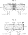
- FIGS. 2A and 2B the brightness of the projection image displayed on the screen SRN is shown in shades. In FIGS. 2A and 2B , only the projectors PJa and PJb and the screen SRN are shown in order to make the projection image easy to see.
- the projector PJa projects an image IMa on the screen SRN.
- the light shielding plate 10a is arranged corresponding to the projector PJa so as to light-block a part of the image IMa.
- the light shielding plate 10a is arranged such that the right side region of the image IMa is blocked by the light shielding plate 10a. Therefore, the projector PJa projects the shadow of the light shielding plate 10a on the screen SRN as a part of the image IMa.
- the region blocked by the light shielding plate 10a corresponds to the shadow region of the light shielding plate 10a.
- the degree of light shielding by the light shielding plate 10a increases toward the right end. Therefore, in the image IMa projected on the screen SRN, the degree of shadow of the light shielding plate 10a increases toward the right end. For that reason, in the image IMa projected on the screen SRN, the right region IMRa continuously darkens toward the right end.
- the image IMa projected on the screen SRN is referred to as a projection image PIMa.
- the projector PJb projects an image IMb on the screen SRN.
- the light shielding plate 10b is arranged corresponding to the projector PJb so as to light-block a part of the image IMb.
- the light shielding plate 10b is arranged such that the left side region of the image IMb is blocked by the light shielding plate 10b. Therefore, the projector PJb projects the shadow of the light shielding plate 10b on the screen SRN as a part of the image IMb.
- the region blocked by the light shielding plate 10b corresponds to the shadow region of the light shielding plate 10b.
- the degree of light shielding by the light shielding plate 10b increases toward the left end. Therefore, in the image IMb projected on the screen SRN, the degree of shadow of the light shielding plate 10b increases toward the left end. For that reason, in the image IMb projected on the screen SRN, the left region IMLb continuously darkens toward the left end.
- the image IMb projected on the screen SRN is referred to as a projection image PIMb.
- the projector PJa and the projector PJb project the image IMa and the image IMb on the screen SRN so that the right region IMRa of the projection image PIMa and the left region IMLb of the projection image PIMb overlap each other.
- the multi-projection system 1 displays the images IMa and IMb projected by the plurality of projectors PJa and PJb on the screen SRN as a multi-projection image MPIM so that a part of the regions light-shielded by the light shielding plate 10 in the plurality of projection images PIM, specifically, the region IMRa blocked by the light shielding plate 10a in the projection image PIMa and the region IMLb blocked by the light shielding plate 10b in the projection image PIMb, overlap each other.
- the multi-projection system 1 can display, on the screen SRN, the multi-projection image MPIM which has been optically edge blended by the light shielding plates 10a and 10b so that the brightness of the overlapping area between the projection image PIMa and the projection image PIMb is the same as the brightness of other areas.
- a projector 100 according to the first embodiment illustrated in FIG. 3 corresponds to the projector PJ (PJa and PJb) illustrated in FIGS. 1 , 2A and 2B .
- the projector 100 includes a light source 101, a phosphor 102, dichroic mirrors 120, lenses 131 to 137, reflection mirrors 141 to 143, a phase difference plate 103, and a polarization conversion element 150.
- the phase difference plate 103 is defined as a first phase difference plate.
- the projector 100 includes dichroic mirrors 105 and 106, reflective polarizing plates 107R, 107G, and 107B, image display elements 108R, 108G, and 108B, a color combining prism 109, an aperture 110, and a projection lens 111.
- the dichroic mirror 120 is defined as a first dichroic mirror
- the dichroic mirror 105 is defined as a second dichroic mirror
- the dichroic mirror 106 is defined as a third dichroic mirror.
- the light source 101 is a blue laser light source having an array structure in which a plurality of blue laser elements BL are arranged.
- the light source 101 emits blue laser light rays from each of the plurality of blue laser elements BL.
- the blue laser light rays are s-polarized or p-polarized linearly polarized light.
- FIG. 3 illustrates a case where the blue laser light rays are s-polarized linearly polarized light.
- the blue laser light rays are irradiated onto the dichroic mirrors 120.
- the light source 101 is defined as a first illumination light source and the blue laser light ray is defined as a first illumination light ray.
- the s-polarized light is defined as a first polarized light and the p-polarized light is defined as a second polarized light.
- the dichroic mirrors 120 are arranged such that a polarization direction of the blue laser light ray is s-polarized with respect to the dichroic mirror 120.
- the dichroic mirror 120 has an optical property of reflecting s-polarized light and transmitting p-polarized light with respect to blue laser light rays.
- the lens 131 is a condenser lens, for example.
- the blue laser light rays emitted from the light source 101 are reflected by the dichroic mirrors 120, further condensed by the lens 131, and irradiated onto the phosphor 102.
- the phosphor 102 has a fluorescent layer and a reflective surface.
- the fluorescent layer generates yellow illumination light rays including a red band component and a green band component having an intensity corresponding to the energy intensity of the light emitted from the light source 101, specifically, corresponding to the energy intensity of the blue laser light rays emitted from the light source 101.
- the reflective surface reflects the blue laser light rays transmitted through the fluorescent layer and the yellow illumination light rays generated by the fluorescent layer.
- the phosphor 102 is defined as a second illumination light source and the yellow illumination light ray is defined as a second illumination light ray. Therefore, the projector 100 includes the light source 101 (blue laser element BL) which is the first illumination light source and the phosphor 102 which is the second illumination light source as a plurality of illumination light sources.
- the yellow illumination light rays which are the fluorescence rays generated by the phosphor 102 are irradiated onto the dichroic mirrors 120 via the lens 131.
- a part of the blue laser light rays is diffused by the phosphor 102 and becomes a random polarized light in which a plurality of polarized light are mixed, and then is irradiated onto the dichroic mirrors 120 via the lens 131. That is, the dichroic mirrors 120 are arranged on the optical path of the blue laser light rays and the yellow illumination light rays.
- the dichroic mirror 120 has an optical property of transmitting yellow illumination light rays.
- FIG. 4A illustrates a configuration example of the dichroic mirrors 120.
- FIG. 4A illustrates a state in which the dichroic mirrors 120 are viewed from the side opposite to the light source 101, that is, a state in which the dichroic mirrors 120 are viewed from the lower side in FIG. 3 .
- the dichroic mirrors 120 have specific polarization reflection areas 120R and transmission areas 120T.
- the specific polarization reflection area 120R reflects the s-polarized light in the blue laser light rays and transmits the p-polarized light in the blue laser light rays and the yellow illumination light rays.
- the transmission area 120T transmits all polarized light including the s-polarized light and the p-polarized light in the blue laser light rays and the yellow illumination light rays.
- the specific polarization reflection area 120R is arranged on an optical axis BLA of the blue laser element BL.
- the specific polarization reflection area 120R is formed so as to have an area larger than the luminous flux width of the blue laser light ray. Therefore, all the blue laser light rays emitted from the plurality of blue laser elements BL are reflected toward the lens 131 by the dichroic mirrors 120. Further, the blue laser light rays are condensed by the lens 131 and are irradiated onto the phosphor 102.
- the specific polarization reflection area 120R is formed so as to have an area smaller than the luminous flux width of the diffused light rays emitted from the phosphor 102 through the lens 131.
- the p-polarized light component is transmitted through the specific polarization reflection areas 120R and the s-polarized light component is reflected by the specific polarization reflection areas 120R and returned to the light source 101.
- the blue laser light rays emitted from the phosphor 102 to the transmission areas 120T passes through the transmission areas 120T.
- the blue laser light rays transmitted through the dichroic mirrors 120 are defined as blue illumination light rays.
- the yellow illumination light rays emitted from the phosphor 102 and irradiated onto the dichroic mirrors 120 via the lens 131 pass through the specific polarization reflection areas 120R and the transmission areas 120T.
- the dichroic mirrors 120 may be configured such that the specific polarization reflection areas 120R are arranged on the optical axes BLA of the blue laser elements BL and the areas other than the specific polarization reflection areas 120R are defined as the transmission areas 120T.
- the dichroic mirror 120 can be manufactured by forming a dielectric multilayer film, for example, on a predetermined region of a transparent material such as a glass plate or a prism. The region where the dielectric multilayer film is formed becomes the specific polarization reflection area 120R.
- the optical properties of the specific polarization reflection area 120R can be set according to the material and film thickness of the dielectric material forming the dielectric multilayer film.
- FIGS. 5A, 5B , 6A, 6B , 7A, 7B , 8A, and 8B illustrate a case where the dichroic mirror 120 has the shape illustrated in FIG. 4A .
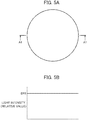
- FIG. 5A illustrates the brightness distributions of the red illumination light rays and the green illumination light rays included in the yellow illumination light rays at the position Pa in shades.
- FIG. 5B illustrates the brightness distribution of the red illumination light rays and the green illumination light rays in A1-A1 illustrated in FIG. 5A as a light intensity distribution.
- the red illumination light rays are composed of the components in the red band included in the yellow illumination light rays
- the green illumination light rays are composed of the components in the green band included in the yellow illumination light rays.
- the yellow illumination light rays pass through the specific polarization reflection areas 120R and the transmission areas 120T of the dichroic mirrors 120. Therefore, at the position Pa, as illustrated in FIG. 5A or 5B , the brightness (light intensity) distribution of the red illumination light rays and the green illumination light rays is uniform.
- the light intensity of the red illumination light rays and the green illumination light rays at the position Pa is set as a BR1.
- FIG. 6A corresponds to FIG. 5A and illustrates the brightness distribution of the blue illumination light rays in shades.
- FIG. 6B illustrates the brightness distribution of the blue illumination light rays in A2-A2 illustrated in FIG. 6A as the light intensity distribution.
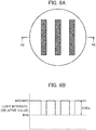
- FIG. 7A corresponds to FIG. 6A and illustrates the brightness distribution of the s-polarized light in the blue illumination light rays in shades.
- FIG. 7B illustrates the brightness distribution of the s-polarized light in the blue illumination light rays in A3-A3 illustrated in FIG. 7A as a light intensity distribution.
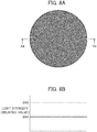
- FIG. 8A corresponds to FIG. 6A and illustrates the brightness distribution of the p-polarized light in the blue illumination light rays in shades.
- FIG. 8B illustrates the brightness distribution of the p-polarized light in the blue illumination light rays in A4-A4 illustrated in FIG. 8A as a light intensity distribution.
- the s-polarized light in the blue illumination light rays pass through the transmission areas 120T of the dichroic mirrors 120 and are reflected at the specific polarization reflection areas 120R. Therefore, the s-polarized light in the blue illumination light rays are eventually blocked by the specific polarization reflection areas 120R. Therefore, at the position Pa, as illustrated in FIG. 7A , the s-polarized light in the blue illumination light rays have a brightness (light intensity) distribution in which the region corresponding to the specific polarization reflection areas 120R is light-blocked and the region corresponding to the transmission areas 120T is darker than the red illumination light rays and the green illumination light rays.
- the p-polarized light in the blue illumination light rays pass through the specific polarization reflection areas 120R and the transmission areas 120T of the dichroic mirrors 120. Therefore, at the position Pa, as illustrated in FIG. 8A , the p-polarized light in the blue illumination light rays are darker than the red illumination light rays and the green illumination light rays and the brightness (light intensity) distribution is uniform. That is, the p-polarized light in the blue illumination light rays have a light intensity BR4 (BR4 ⁇ BR1) smaller than the light intensity BR1 of the red illumination light rays and the green illumination light rays at the position Pa, as illustrated in FIG. 8B .
- the blue illumination light rays including the s-polarized light having the brightness (light intensity) distribution illustrated in FIGS. 7A and 7B and the p-polarized light having the brightness (light intensity) distribution illustrated in FIGS. 8A and 8B have a brightness (light intensity) distribution in which the region corresponding to the transmission areas 120T has the same brightness as the red illumination light rays and the green illumination light rays, and the region corresponding to the specific polarization reflection areas 120R is darker than the red illumination light rays and the green illumination light rays.
- the difference between the light intensity BR5 and the light intensity BR6 of the blue illumination light rays at the position Pa is defined as a light intensity difference BRDa.
- the lenses 132 and 133 illustrated in FIG. 3 are fly-eye lenses, for example. As illustrated in FIG. 3 , the blue illumination light rays and the yellow illumination light rays transmitted through the dichroic mirrors 120 are reflected by the reflection mirrors 141. Further, in the blue illumination light rays and the yellow illumination light rays, the illumination distributions of the red illumination light rays, the green illumination light rays, and the blue illumination light rays irradiated onto the image display elements 108R, 108G, and 108B are made uniform by the lenses 132 and 133.
- the phase difference plate 103 is arranged between the dichroic mirrors 120 and the polarization conversion element 150 on the optical path of the blue illumination light rays and the yellow illumination light rays.
- FIG. 3 illustrates, as an example, a state in which the phase difference plate 103 is arranged between the lens 132 and the lens 133.
- the phase difference plate 103 is arranged in a direction of converting linearly polarized light into circularly polarized light.
- the phase difference plate 103 is a ⁇ /4 phase difference plate, for example.
- FIGS. 9A, 9B , 10A, 10B , 11A, 11B , 12A, and 12B respectively correspond to FIGS. 5A, 5B , 6A, 6B , 7A, 7B , 8A, and 8B .
- FIG. 9A illustrates the distribution of the brightness of the red illumination light rays and the green illumination light rays included in the yellow illumination light rays in shades.
- FIG. 9B illustrates the distribution of the brightness of the red illumination light rays in A5-A5 illustrated in FIG. 9A and the green illumination light rays as the light intensity distribution.
- the brightness (light intensity) distribution of the red illumination light rays and the green illumination light rays is uniform.
- the light intensity of the red illumination light rays and the green illumination light rays at the position Pb is defined as BR7.
- FIG. 10A corresponds to FIG. 9A and illustrates the distribution of the brightness of the blue illumination light rays in shades.
- FIG. 10B illustrates the distribution of the brightness of the blue illumination light rays in A6-A6 illustrated in FIG. 10A as the light intensity distribution.
- FIG. 11A corresponds to FIG. 10A and illustrates the distribution of the brightness of s-polarized light in the blue illumination light rays in shades.
- FIG. 11B illustrates the distribution of the brightness of the s-polarized light of the blue illumination light rays in A7-A7 illustrated in FIG. 11A as the light intensity distribution.
- FIG. 12A corresponds to FIG. 10A and illustrates the distribution of the brightness of the p-polarized light in the blue illumination light rays in shades.
- FIG. 12B illustrates the distribution of the brightness of the p-polarized light in the blue illumination light rays in A8-A8 illustrated in FIG. 12A as the light intensity distribution.
- the phase difference plate 103 converts the blue illumination light rays that are linearly polarized light into circularly polarized light. As illustrated in FIGS. 11A and 12A , the phase difference plate 103 converts the blue illumination light rays into circularly polarized light, thereby making the s-polarized light and the p-polarized light in the blue illumination light rays have the same brightness (light intensity) distribution.
- the s-polarized light and the p-polarized light in the blue illumination light rays have a the brightness (light intensity) distribution in which the region corresponding to the transmission areas 120T is darker than the red illumination light rays and the green illumination light rays, and the region corresponding to the specific polarization reflection areas 120R is even darker than the region corresponding to the transmission areas 120T.
- the region corresponding to the transmission areas 120T has a light intensity BR8 (BR8 ⁇ BR7) smaller than the light intensity BR7 of the red illumination light rays and the green illumination light rays, and the region corresponding to the specific polarization reflection areas 120R has a light intensity BR9 (BR9 ⁇ BR8) smaller than the light intensity BR8 of the region corresponding to the transmission areas 120T.
- the region corresponding to the transmission areas 120T has a light intensity BR10 (BR10 ⁇ BR7) smaller than the light intensity BR7 of the red illumination light rays and the green illumination light rays, and the region corresponding to the specific polarization reflection areas 120R has a light intensity BR11 (BR11 ⁇ BR10) smaller than the light intensity BR10 of the region corresponding to the transmission areas 120T.
- the blue illumination light rays including the s-polarized light having the brightness (light intensity) distribution illustrated in FIGS. 11A and 11B and the p-polarized light having the brightness (light intensity) distribution illustrated in FIGS. 12A and 12B have a brightness (light intensity) distribution in which the region corresponding to the transmission areas 120T has the same brightness as the red illumination light rays and the green illumination light rays, and the region corresponding to the specific polarization reflection areas 120R is darker than the red illumination light rays and the green illumination light rays.
- the difference between the light intensity BR12 and the light intensity BR13 of the blue illumination light rays at the position Pb is defined as a light intensity difference BRDb.
- the s-polarized light intensities BR8 and BR9 and the p-polarized light intensities BR10 and BR11 in the blue illumination light rays have the same value.
- the light intensity difference BRDa and the light intensity difference BRDb are substantially the same values.
- the polarization conversion element 150 is arranged on the optical path of the blue illumination light rays and the yellow illumination light rays transmitted through the phase difference plate 103.
- the blue illumination light rays and the yellow illumination light rays transmitted through the phase difference plate 103 are incident on the polarization conversion element 150.
- FIG. 13 illustrates a configuration example of the polarization conversion element 150.
- the polarization conversion element 150 includes a polarization beam splitter 151 and a phase difference plate 152.
- the phase difference plate 152 is defined as a second phase difference plate.
- the polarization beam splitter 151 reflects either s-polarized light or p-polarized light and transmits the other.
- FIG. 13 illustrates a state in which the polarization beam splitter 151 reflects s-polarized light and transmits p-polarized light.
- the phase difference plate 152 converts either s-polarized light or p-polarized light into the other.
- FIG. 13 illustrates a state in which the phase difference plate 152 converts s-polarized light into p-polarized light.
- the phase difference plate 152 is a ⁇ /2 phase difference plate, for example.
- the specific polarization reflection areas 120R of the dichroic mirrors 120 and the phase difference plate 152 of the polarization conversion element 150 correspond to each other.
- FIGS. 14A, 14B , 15A, 15B , 16A, 16B , 17A, and 17B The position Pc corresponds to the position of an illumination pupil.
- FIGS. 14A, 14B , 15A, 15B , 16A, 16B , 17A, and 17B respectively correspond to FIGS. 9A, 9B , 10A, 10B , 11A, 11B , 12A, and 12B .
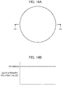
- FIG. 14A illustrates the distribution of the brightness of the red illumination light rays and the green illumination light rays included in the yellow illumination light rays in shades.
- FIG. 14B illustrates the distribution of the brightness of the red illumination light rays and the green illumination light rays in A9-A9 illustrated in FIG. 14A as the light intensity distribution.
- the yellow illumination light rays are aligned to p-polarized light by the polarization conversion element 150.
- the illumination pupil (position Pc) as illustrated in FIG. 14A , the brightness (light intensity) distribution of the red illumination light rays and the green illumination light rays is uniform.
- the light intensity of the red illumination light rays and the green illumination light rays in the illumination pupil is defined as BR14.
- FIG. 15A corresponds to FIG. 14A and illustrates the distribution of the brightness of the blue illumination light rays in the illumination pupil (position Pc) in shades.
- FIG. 15B illustrates the distribution of the brightness of the blue illumination light rays in A10-A10 illustrated in FIG. 15A as the light intensity distribution.
- FIGS. 16A and 17A correspond to FIG. 15A and illustrate the distribution of the brightness of the blue illumination light rays in shades.
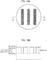
- FIG. 16B illustrates the distribution of the brightness of the blue illumination light rays in A11-A11 illustrated in FIG. 16A as the light intensity distribution.
- FIG. 17B illustrates the distribution of the brightness of the blue illumination light rays in A12-A12 illustrated in FIG. 17A as the light intensity distribution.
- FIGS. 16A and 16B correspond to FIGS. 11A and 11B .
- the brightness (light intensity) distribution of the blue illumination light rays illustrated in FIGS. 16A and 16B corresponds to the brightness (light intensity) distribution of the s-polarized light in the blue illumination light rays incident on the polarization conversion element 150.
- FIGS. 17A and 17B correspond to FIGS. 12A and 12B , respectively.
- the brightness (light intensity) distribution of the blue illumination light rays illustrated in FIGS. 17A and 17B corresponds to the brightness (light intensity) distribution of the p-polarized light in the blue illumination light rays incident on the polarization conversion element 150.
- the polarization conversion element 150 transmits p-polarized light.
- the p-polarized light in the blue illumination light rays incident on the polarization conversion element 150 has a brightness (light intensity) distribution in which the region corresponding to the transmission areas 120T is darker than the red illumination light rays and the green illumination light rays, and the region corresponding to the specific polarization reflection areas 120R is darker than the region corresponding to the transmission areas 120T, and the p-polarized light transmit the polarization conversion element 150.
- the region corresponding to the transmission areas 120T has a light intensity BR19 (BR19 ⁇ BR14) smaller than the light intensity BR14 of the red illumination light rays and the green illumination light rays
- the region corresponding to the specific polarization reflection areas 120R has a light intensity BR20 (BR20 ⁇ BR19) smaller than the light intensity BR19 in the region corresponding to the transmission areas 120T
- the p-polarized light transmit the polarization conversion element 150.
- the polarization conversion element 150 shifts the optical axis of the s-polarized light in a reflection direction by reflecting the s-polarized light incident on the polarization conversion element 150 in the polarization beam splitter 151.
- the polarization conversion element 150 converts s-polarized light into p-polarized light by the phase difference plate 152. Therefore, the blue illumination light rays are aligned to p-polarized light by the polarization conversion element 150.
- the s-polarized light in the blue illumination light rays incident on the polarization conversion element 150 are emitted from the polarization conversion element 150 as p-polarized blue illumination light rays having a brightness (light intensity) distribution in which the brightness (light intensity) distribution illustrated in FIGS. 11A and 11B is shifted in the reflection direction by the polarization conversion element 150.
- the s-polarized light in the blue illumination light rays incident on the polarization conversion element 150 become p-polarized blue illumination light rays having the brightness (light intensity) distribution in which the region corresponding to the transmission areas 120T is darker than the red illumination light rays and the green illumination light rays, and the region corresponding to the specific polarization reflection areas 120R is darker than the region corresponding to the transmission area 120T, and the p-polarized blue illumination light rays are emitted from the polarization conversion element 150.
- the s-polarized light in the blue illumination light rays incident on the polarization conversion element 150 become the p-polarized blue illumination light rays where the region corresponding to the transmission areas 120T has a light intensity BR17 (BR17 ⁇ BR14) smaller than the light intensity BR14 of the red illumination light rays and the green illumination light rays, and the region corresponding to the specific polarization reflection areas 120R has a light intensity BR18 (BR18 ⁇ BR17) smaller than the light intensity BR17 in the region corresponding to the transmission areas 120T, and the p-polarized blue illumination light rays are emitted from the polarization conversion element 150.
- the blue illumination light rays aligned to p-polarized light by the polarization conversion element 150 have the brightness (light intensity) distribution in which the region corresponding to the transmission areas 120T has the same brightness as the red illumination light rays and the green illumination light rays, and the region corresponding to the specific polarization reflection areas 120R is darker than the red illumination light rays and the green illumination light rays.
- the difference between the light intensity BR15 and the light intensity BR16 of the blue illumination light rays in the illumination pupil (position Pc) is defined as a light intensity difference BRDc.
- the blue illumination light rays emitted from the plurality of blue laser elements BL forming the light source 101 are converted from linearly polarized light to circularly polarized light by the phase difference plate 103, and then the polarization conversion element 150 transmits the p-polarized light in the blue illumination light rays and shifts the optical axis of the s-polarized light.
- the projector 100 and the multi-projection system 1 since the light intensity difference BRDc of the blue illumination light rays at the illumination pupil (position Pc) can be made smaller than the light intensity differences BRDa and BRDb of the blue illumination light rays at the positions Pa and Pb, it is possible to reduce the variation in the brightness of the blue illumination light rays.
- the dichroic mirror 105 is arranged on the optical path of the blue illumination light rays and the yellow illumination light rays transmitted through the polarization conversion element 150.
- the blue illumination light rays and the yellow illumination light rays aligned to P-polarized light by the polarization conversion element 150 are irradiated onto the dichroic mirror 105 via the lens 134.
- the lens 134 is a condenser lens, for example.
- the dichroic mirror 105 separates the incident blue illumination light rays and the yellow illumination light rays.
- Yellow illumination light rays YLL separated by the dichroic mirror 105 are reflected by the reflection mirror 142.
- the dichroic mirror 106 is arranged on the optical path of the yellow illumination light rays YLL.
- the yellow illumination light rays YLL reflected by the reflection mirror 142 is irradiated onto the dichroic mirror 106.
- the dichroic mirror 106 separates incident light rays by reflection and transmission with the separation wavelength as the separation boundary.
- the dichroic mirror 106 separates the yellow illumination light YLL into red illumination light rays RLL containing red band components and green illumination light rays GLL containing green band components.
- the dichroic mirror 106 reflects the green illumination light rays GLL and transmits the red illumination light rays RLL with respect to the incident yellow illumination light rays YLL to separate it to the green illumination light rays GLL and the red illumination light rays RLL.
- the reflectance of the green illumination light rays GLL and the transmittance of the red illumination light rays RLL are 100% on the short wavelength side and 100% on the long wavelength side with the separation wavelength as a boundary.
- the reflectance of the green illumination light rays GLL and the transmittance of the red illumination light rays RLL become small, so it can be said that the separation boundary has a width centered on the separation wavelength.
- the red illumination light rays RLL contain components in the green wavelength band and the green illumination light rays GLL contain components in the red wavelength band. It is ideal from the viewpoint of light energy utilization efficiency that there is no width of the separation boundary.
- the red illumination light rays RLL separated by the dichroic mirror 106 are irradiated onto the reflective polarizing plate 107R via the lens 135.
- the green illumination light rays GLL separated by the dichroic mirror 106 are irradiated onto the reflective polarizing plate 107G via the lens 136.
- the blue illumination light rays BLL separated by the dichroic mirror 105 are reflected by the reflection mirror 143 and irradiated onto the reflective polarizing plate 107B via the lens 137.
- the reflective polarizing plates 107R, 107G, and 107B reflect either s-polarized light or p-polarized light and transmit the other.
- FIG. 3 illustrates a state in which the reflective polarizing plates 107R, 107G, and 107B reflect s-polarized light and transmit p-polarized light.
- Wire grids may be used as the reflective polarizing plates 107R, 107G, and 107B.
- the image display element 108R photomodulates the red illumination light rays RLL based on the image data of the red components to generate s-polarized red image light rays RML.
- the image display element 108G photomodulates the green illumination light rays GLL based on the image data of the green components to generate s-polarized green image light rays GML.
- the image display element 108B photomodulates the blue illumination light rays BLL based on the image data of the blue components to generate the s-polarized blue image light rays BML.
- the image display element 108R functions as a light modulation element for a red image
- the image display element 108G functions as a light modulation element for a green image
- the image display element 108B functions as a light modulation element for a blue image.
- the red image light rays RML, the green image light rays GML, and the blue image light rays BML generated by the image display elements 108R, 108G, and 108B are respectively reflected by the reflective polarizing plates 107R, 107G, and 107B and are irradiated onto the color combining prism 109.
- the color combining prism 109 reflects the red image light rays RML and the blue image light rays BML and transmits the green image light rays GML to combine the red image light rays RML, the green image light rays GML, and the blue image light rays BML.
- the red image light rays RML, the green image light rays GML, and the blue image light rays BML synthesized by the color combining prism 109 are projected onto the screen SRN or the like via the aperture 110 and the projection lens 111 as illustrated in FIG. 1 or 3 .
- the projector 100 displays the full-color image IM in which the red image light rays RML, the green image light rays GML, and the blue image light rays BML are combined on the screen SRN or the like.
- the position Pd of the aperture 110 corresponds to the position of the projection pupil.
- the illumination pupil and the projection pupil have a conjugate relationship. Therefore, the brightness distribution of the red image light rays RML, the green image light rays GML, and the blue image light rays BML at the position Pd corresponding to the position of the projection pupil corresponds to the brightness distribution of the red illumination light rays RLL, the green illumination light rays GLL, and the blue illumination light rays BLL at the position Pc corresponding to the position of the illumination pupil.
- a comparative example is a state in which the phase difference plate 103 is not arranged.
- the brightness distribution of the red image light rays RML, the green image light rays GML, and the blue image light rays BML at the position Pd corresponding to the position of the projection pupil corresponds to the brightness distribution of the red illumination light rays RLL, the green illumination light rays GLL, and the blue illumination light rays BLL at the position Pa.
- the projector 100 and the multi-projection system 1 by converting the blue illumination light rays BLL into circularly polarized light by the phase difference plate 103, and further shifting the optical axis of the s-polarized light of the blue illumination light rays by the polarization conversion element 150, it is possible to reduce the variation in the brightness of the blue image light rays BLL in the projection pupil as compared with the comparative example.
- the color distribution caused by the light shielding plate 10 can be reduced by reducing the variation in the brightness of the blue image light rays BLL in the projection pupil.
- the projector 100 and the multi-projection system 1 when the projector 100 includes the blue laser element BL and the phosphor 102 which are a plurality of illumination light sources, deterioration of the quality of the multi-projection image can be suppressed.
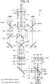
- a configuration example of the projector PJ will be described with reference to FIG. 18 .
- a projector 200 according to the second embodiment illustrated in FIG. 18 corresponds to the projector PJ (PJa and PJb) illustrated in FIGS. 1 , 2A , and 2B .
- FIG. 18 corresponds to FIG. 3 .
- the similar components as that of the projector 100 according to the first embodiment are designated by the same reference numerals and letters.
- the projector 200 according to the second embodiment is different from the projector 100 according to the first embodiment in the configuration of a dichroic mirror 220 corresponding to the dichroic mirrors 120 and the positional relationship between the light source 101 and the phosphor 102 with respect to the dichroic mirror 220.
- the projector 200 includes a light source 101, a phosphor 102, the dichroic mirror 220, lenses 131 to 137, reflection mirrors 141 to 143, a phase difference plate 103, and a polarization conversion element 150.
- the phase difference plate 103 is defined as the first phase difference plate.
- the projector 200 includes dichroic mirrors 105 and 106, reflective polarizing plates 107R, 107G, and 107B, image display elements 108R, 108G, and 108B, a color combining prism 109, an aperture 110, and a projection lens 111.
- the dichroic mirror 220 is defined as a first dichroic mirror
- the dichroic mirror 105 is defined as a second dichroic mirror
- the dichroic mirror 106 is defined as a third dichroic mirror.
- the light source 101 emits blue laser light rays from each of a plurality of blue laser elements BL.
- the blue laser light rays are s-polarized or p-polarized linearly polarized light.
- FIG. 18 illustrates a case where the blue laser light rays are p-polarized linearly polarized light.
- the dichroic mirror 220 is irradiated with the blue laser light rays.
- the light source 101 is defined as a first illumination light source and the blue laser light ray is defined as a first illumination light ray.
- the s-polarized light is defined as a first polarized light and the p-polarized light is defined as a second polarized light.
- the dichroic mirror 220 is arranged so that the polarization direction of the blue laser light ray is s-polarized with respect to the dichroic mirror 220.
- the dichroic mirror 220 has an optical property of reflecting s-polarized light and transmitting p-polarized light with respect to blue laser light rays.
- the blue laser light rays emitted from the light source 101 pass through the dichroic mirror 220, are further condensed by the lens 131, and the phosphor 102 is irradiated with the blue laser light rays.
- the phosphor 102 has a fluorescent layer and a reflective surface.
- the fluorescent layer generates yellow illumination light rays including a red band component and a green band component having an intensity corresponding to the energy intensity of the light emitted from the light source 101, specifically, corresponding to the energy intensity of the blue laser light rays emitted from the light source 101.
- the reflective surface reflects the blue laser light rays transmitted through the fluorescent layer and the yellow illumination light rays generated by the fluorescent layer.
- the phosphor 102 is defined as a second illumination light source, and the yellow illumination light ray is defined as a second illumination light. Therefore, the projector 200 includes the light source 101 (blue laser element BL) which is the first illumination light source and the phosphor 102 which is the second illumination light source as a plurality of illumination light sources.
- the yellow illumination light rays which are the fluorescence rays generated by the phosphor 102 are irradiated onto the dichroic mirror 220 via the lens 131.
- a part of the blue laser light rays is diffused by the phosphor 102 and becomes a random polarized light in which a plurality of polarized light are mixed, and then is irradiated onto the dichroic mirror 220 via the lens 131. That is, the dichroic mirror 220 is arranged on the optical path of the blue laser light rays and the yellow illumination light rays.
- the dichroic mirror 220 has an optical property of reflecting yellow illumination light rays.
- FIG. 19A illustrates a configuration example of the dichroic mirror 220.
- FIG. 19A illustrates a state in which the dichroic mirror 220 is viewed from the side opposite to the light source 101, that is, a state in which the dichroic mirror 220 is viewed from the lower side in FIG. 18 .
- the dichroic mirror 220 has a specific polarization reflection areas 220R and a total reflection areas 220T.
- the specific polarization reflection areas 220R transmit the p-polarized light in the blue laser light rays and reflect the s-polarized light in the blue laser light rays and the yellow illumination light rays.
- the total reflection areas 220T reflect all the polarized light including the s-polarized light and the p-polarized light in the blue laser light rays and the yellow illumination light rays.
- the specific polarization reflection area 220R is arranged on the optical axis BLA of the blue laser element BL.
- the specific polarization reflection area 220R is formed so as to have an area larger than the luminous flux width of the blue laser light ray. Therefore, all of the blue laser light rays emitted from the plurality of blue laser elements BL pass through the dichroic mirror 220 and the lens 131 is irradiated with the blue laser light rays. Further, the blue laser light rays are condensed by the lens 131 and are irradiated onto the phosphor 102.
- the specific polarization reflection area 220R is formed so as to have an area smaller than the luminous flux width of the diffused light rays emitted from the phosphor 102 through the lens 131.
- the s-polarized light component is reflected toward the reflection mirror 141 by the specific polarization reflection areas 220R.
- the p-polarized light component passes through the specific polarization reflection areas 220R and is returned to the light source 101.
- the blue laser light rays emitted from the phosphor 102 and irradiated onto the total reflection areas 220T are reflected by the total reflection areas 220T toward the reflection mirror 141.
- the blue laser light rays reflected toward the reflection mirror 141 by the dichroic mirror 220 are defined as blue illumination light rays.
- the yellow illumination light rays emitted from the phosphor 102 and irradiated onto the dichroic mirror 220 via the lens 131 are reflected toward the reflection mirror 141 by the specific polarization reflection areas 220R and the total reflection areas 220T.
- the dichroic mirror 220 may be configured such that the specific polarization reflection areas 220R are arranged on the optical axes BLA of the blue laser element BL and the region other than the specific polarization reflection areas 220R is defined as a total reflection area 220T.
- the dichroic mirror 220 can be manufactured by forming a dielectric multilayer film, for example, in the region to be the specific polarization reflection areas 220R, and by forming a reflective film such as a metal film or a dielectric multilayer film in the region to be the total reflection area (areas) 220T, using a transparent material such as a glass plate or a prism.
- the optical properties of the specific polarization reflection area 220R can be set according to the material and film thickness of the dielectric material forming the dielectric multilayer film.
- FIGS. 20A, 20B , 21A, 21B , 22A, 22B , 23A, and 23B illustrate a case where the dichroic mirror 220 has the shape illustrated in FIG. 19A .
- the position Pe illustrated in FIG. 18 corresponds to the position Pa illustrated in FIG. 3 .
- the region corresponding to the specific polarization reflection areas 220R at the position Pe corresponds to the region corresponding to the specific polarization reflection areas 120R at the position Pa.
- the region corresponding to the total reflection areas 220T at the position Pe corresponds to the region corresponding to the transmission areas 120T at the position Pa.
- FIG. 20A illustrates the distribution of the brightness of the red illumination light rays and the green illumination light rays included in the yellow illumination light rays at the position Pe in shades.
- FIG. 21B illustrates the distribution of the brightness of the red illumination light rays and the green illumination light rays in A21-A21 illustrated in FIG. 20A as the light intensity distribution.
- the red illumination light rays are composed of the red band components contained in the yellow illumination light rays and the green illumination light rays are composed of the green band components contained in the yellow illumination light rays.
- the yellow illumination light rays are reflected at the specific polarization reflection areas 220R and the total reflection areas 220T of the dichroic mirror 220. Therefore, at the position Pe, as illustrated in FIG. 20A or 20B , the brightness (light intensity) distribution of the red illumination light rays and the green illumination light rays is uniform.
- the light intensity of the red illumination light rays and the green illumination light rays at the position Pe is set as a BR21.
- the brightness (light intensity) distribution of the red illumination light rays and the green illumination light rays illustrated in FIGS. 20A and 20B corresponds to the brightness (light intensity) distribution of the red illumination light rays and the green illumination light rays illustrated in FIGS. 5A and 5B .
- the light intensity BR21 of the red illumination light rays and the green illumination light rays at the position Pe corresponds to the light intensity BR1 of the red illumination light rays and the green illumination light rays at the position Pa.
- FIG. 21A corresponds to FIG. 20A and illustrates the distribution of the brightness of the blue illumination light rays in shades.
- FIG. 21B illustrates the distribution of the brightness of the blue illumination light rays in A22-A22 illustrated in FIG. 21A as the light intensity distribution.
- FIG. 22A corresponds to FIG. 21A and illustrates the distribution of the brightness of s-polarized light in the blue illumination light rays in shades.
- FIG. 22B illustrates the distribution of the brightness of the s-polarized light in the blue illumination light rays in A23-A23 illustrated in FIG. 22A as the light intensity distribution.
- FIG. 23A corresponds to FIG. 21A and illustrates the distribution of the brightness of the p-polarized light in the blue illumination light rays in shades.
- FIG. 23B illustrates the distribution of the brightness of the p-polarized light in the blue illumination light rays in A24-A24 illustrated in FIG. 23A as the light intensity.
- the s-polarized light in the blue illumination light rays are reflected at the specific polarization reflection areas 220R and the total reflection areas 220T of the dichroic mirror 220. Therefore, at the position Pe, as illustrated in FIG. 22A , the s-polarized light in the blue illumination light rays are darker than the red illumination light rays and the green illumination light rays and the brightness (light intensity) distribution is uniform. That is, as illustrated in FIG. 22B , the s-polarized light in the blue illumination light rays have a light intensity BR22 (BR22 ⁇ BR21) smaller than the light intensity BR21 of the red illumination light rays and the green illumination light rays at the position Pe.
- BR22 BR22 ⁇ BR21
- the brightness (light intensity) distribution of s-polarized light in the blue illumination light rays illustrated in FIGS. 22A and 22B corresponds to the brightness (light intensity) distribution of p-polarized light in the blue illumination light rays illustrated in FIGS. 8A and 8B .
- the light intensity BR22 of the s-polarized light in the blue illumination light rays at the position Pe corresponds to the light intensity BR4 of the p-polarized light in the blue illumination light rays at the position Pa.
- the p-polarized light in the blue illumination light rays pass through the specific polarization reflection areas 220R of the dichroic mirror 220 and are reflected at the total reflection areas 220T. Therefore, the p-polarized light in the blue illumination light rays are not irradiated onto the region corresponding to the specific polarization reflection areas 220R at the position Pe. Therefore, at the position Pe, as illustrated in FIG. 23A , the p-polarized light in the blue illumination light rays are not irradiated onto the region corresponding to the specific polarization reflection areas 220R, and the region corresponding to the total reflection areas 220T has a brightness (light intensity) distribution darker than the red illumination light rays and the green illumination light rays.
- the brightness (light intensity) distribution of the p-polarized light in the blue illumination light rays illustrated in FIGS. 23A and 23B corresponds to the brightness (light intensity) distribution of the s-polarized light in the blue illumination light rays illustrated in FIGS. 7A and 7B .
- the light intensities BR23 and BR24 of the p-polarized light in the blue illumination light rays at the position Pe correspond to the light intensities BR2 and BR3 of the s-polarized light in the blue illumination light rays at the position Pa.
- the blue illumination light rays including the s-polarized light having the brightness (light intensity) distribution illustrated in FIGS. 22A and 22B and the p-polarized light having the brightness (light intensity) distribution illustrated in FIGS. 23A and 23B have the brightness (light intensity) distribution in which the region corresponding to the total reflection areas 220T has the same brightness as the red illumination light rays and the green illumination light rays, and the region corresponding to the specific polarization reflection areas 220R is darker than the red illumination light rays and the green illumination light rays.
- the difference between the light intensity BR25 and the light intensity BR26 of the blue illumination light rays at the position Pe is defined as a light intensity difference BRDe.
- the brightness (light intensity) distribution of the blue illumination light rays illustrated in FIGS. 21A and 21B corresponds to the brightness (light intensity) distribution of the blue illumination light rays illustrated in FIGS. 6A and 6B .
- the light intensities BR25 and BR26 of the blue illumination light rays at the position Pe correspond to the light intensities BR5 and BR6 of the blue illumination light rays at the position Pa.
- the light intensity difference BRDe of the blue illumination light rays at the position Pe corresponds to the light intensity difference BRDa of the blue illumination light rays at the position Pa.
- the blue illumination light rays and the yellow illumination light rays which are reflected by the dichroic mirror 220 are further reflected by the reflection mirror 141.
- the illumination distributions of the red illumination light rays, the green illumination light rays, and the blue illumination light rays irradiated onto the image display elements 108R, 108G, and 108B are made uniform by the lenses 132 and 133.
- the phase difference plate 103 is arranged between the dichroic mirror 220 and the polarization conversion element 150 on the optical path of the blue illumination light rays and the yellow illumination light rays.
- FIG. 18 illustrates, as an example, a state in which the phase difference plate 103 is arranged between the lens 132 and the lens 133.
- the phase difference plate 103 is arranged in the direction of converting linearly polarized light into circularly polarized light.
- the phase difference plate 103 is a ⁇ /4 phase difference plate, for example.
- FIGS. 9A, 9B , 10A, 10B , 11A, 11B , 12A, and 12B respectively correspond to FIGS. 20A, 20B , 21A, 21B , 22A, 22B , 23A, and 23B .
- the position Pf illustrated in FIG. 18 corresponds to the position Pb illustrated in FIG. 3 .
- the region corresponding to the specific polarization reflection areas 220R at the position Pf corresponds to the region corresponding to the specific polarization reflection areas 120R at the position Pb.
- the region corresponding to the total reflection areas 220T at the position Pf corresponds to the region corresponding to the transmission areas 120T at the position Pb.
- the brightness (light intensity) distribution of the red illumination light ray and the green illumination light ray is uniform.
- the light intensity of the red illumination light rays and the green illumination light rays at the position Pf is defined as BR27.
- the light intensity BR27 of the red illumination light rays and the green illumination light rays at the position Pf corresponds to the light intensity BR7 of the red illumination light rays and the green illumination light rays at the position Pb.
- the phase difference plate 103 converts the blue illumination light rays that are linearly polarized light into circularly polarized light. As illustrated in FIGS. 11A and 12A , the phase difference plate 103 converts the blue illumination light rays into circularly polarized light, thereby making the s-polarized light and the p-polarized light in the blue illumination light rays have the same brightness (light intensity) distribution.
- the s-polarized light and the p-polarized light in the blue illumination light rays have the brightness (light intensity) distribution in which the region corresponding to the total reflection areas 220T is darker than the red illumination light rays and the green illumination light rays, and the region corresponding to the specific polarization reflection areas 220R is even darker than the region corresponding to the total reflection areas 220T.
- the region corresponding to the total reflection areas 220T has a light intensity BR28 (BR28 ⁇ BR27) smaller than the light intensity BR27 of the red illumination light rays and the green illumination light rays
- the region corresponding to the specific polarization reflection areas 220R has a light intensity BR29 (BR29 ⁇ BR28) smaller than the light intensity BR28 in the region corresponding to the total reflection areas 220T.
- the light intensities BR28 and BR29 of the s-polarized light in the blue illumination light rays at the position Pf correspond to the light intensities BR8 and BR9 of the s-polarized light in the blue illumination light rays at the position Pb.
- the region corresponding to the total reflection areas 220T has a light intensity BR30 (BR30 ⁇ BR27) smaller than the light intensity BR27 of the red illumination light rays and the green illumination light rays
- the region corresponding to the specific polarization reflection areas 220R has a light intensity BR31 (BR31 ⁇ BR30) smaller than the light intensity BR30 in the region corresponding to the total reflection areas 220T.
- the light intensities BR30 and BR31 of the p-polarized light in the blue illumination light rays at the position Pf correspond to the light intensities BR10 and BR11 of the p-polarized light in the blue illumination light rays at the position Pb.
- the blue illumination light rays including the s-polarized light having the brightness (light intensity) distribution illustrated in FIGS. 11A and 11B and the p-polarized light having the brightness (light intensity) distribution illustrated in FIGS. 12A and 12B have the brightness (light intensity) distribution in which the region corresponding to the total reflection areas 220T has the same brightness as the red illumination light rays and the green illumination light rays, and the region corresponding to the specific polarization reflection areas 220R is darker than the red illumination light rays and the green illumination light rays.
- the difference between the light intensity BR32 and the light intensity BR33 of the blue illumination light rays at the position Pf is defined as a light intensity difference BRDf.
- the light intensities BR32 and BR33 of the blue illumination light rays at the position Pf correspond to the light intensities BR12 and BR13 of the blue illumination light rays at the position Pb.
- the light intensity difference BRDf of the blue illumination light rays at the position Pf corresponds to the light intensity difference BRDb of the blue illumination light rays at the position Pb.
- the light intensities BR28 and BR29 of the s-polarized light and the light intensities BR30 and BR31 of the p-polarized light in the blue illumination light rays have the same value.
- the light intensity difference BRDe and the light intensity difference BRDf are almost the same values.
- the polarization conversion element 150 is arranged on the optical path of the blue illumination light rays and the yellow illumination light rays transmitted through the phase difference plate 103.
- the blue illumination light rays and the yellow illumination light rays transmitted through the phase difference plate 103 are incident onto the polarization conversion element 150 illustrated in FIGS. 18 and 13 .
- the specific polarization reflection areas 220R of the dichroic mirror 220 and the phase difference plate 152 of the polarization conversion element 150 correspond to each other.
- the phase difference plate 152 is defined as a second phase difference plate.
- FIGS. 14A, 14B , 15A, 15B , 16A, 16B , 17A, and 17B The position Pg corresponds to the position of the illumination pupil.
- FIGS. 14A, 14B , 15A, 15B , 16A, 16B , 17A, and 17B respectively correspond to FIGS. 9A, 9B , 10A, 10B , 11A, 11B , 12A, and 12B .
- the position Pg illustrated in FIG. 18 corresponds to the position Pc illustrated in FIG. 3 .
- the region corresponding to the specific polarization reflection areas 220R at the position Pg corresponds to the region corresponding to the specific polarization reflection areas 120R at the position Pc.
- the region corresponding to the total reflection areas 220T at the position Pg corresponds to the region corresponding to the transmission areas 120T at the position Pc.
- the yellow illumination light rays are aligned to p-polarized light by the polarization conversion element 150.
- the illumination pupil position Pg
- the brightness (light intensity) distribution of the red illumination light rays and the green illumination light rays is uniform.
- the light intensity of the red illumination light rays and the green illumination light rays in the illumination pupil is defined as BR34.
- the light intensity BR34 of the red illumination light rays and the green illumination light rays at the position Pg corresponds to the light intensity BR14 of the red illumination light rays and the green illumination light rays at the position Pc.
- the polarization conversion element 150 transmits the p-polarized light.
- the p-polarized light in the blue illumination light rays incident onto the polarization conversion element 150 have the brightness (light intensity) distribution in which the region corresponding to the total reflection areas 220T is darker than the red illumination light rays and the green illumination light rays, and the region corresponding to the specific polarization reflection areas 220R is darker than the region corresponding to the total reflection areas 220T, and the p-polarized light pass through the polarization conversion element 150.
- the region corresponding to the total reflection areas 220T has a light intensity BR39 (BR39 ⁇ BR34) smaller than the light intensity BR34 of the red illumination light rays and the green illumination light rays
- the region corresponding to the specific polarization reflection areas 220R has a light intensity BR40 (BR40 ⁇ BR39) smaller than the light intensity BR39 in the region corresponding to the total reflection areas 220T, and the p-polarized light pass through the polarization conversion element 150.
- the light intensities BR39 and BR40 of the p-polarized light in the blue illumination light rays at the position Pg correspond to the light intensities BR19 and BR20 of the p-polarized light in the blue illumination light rays at the position Pc.
- the polarization conversion element 150 shifts the optical axis of the s-polarized light in the reflection direction by reflecting the s-polarized light incident onto the polarization conversion element 150 in the polarization beam splitter 151.
- the polarization conversion element 150 converts the s-polarized light into the p-polarized light by the phase difference plate 152. Therefore, the blue illumination light rays are aligned to the p-polarized light by the polarization conversion element 150.
- the s-polarized light in the blue illumination light rays incident onto the polarization conversion element 150 become p-polarized blue illumination light rays having the brightness (light intensity) distribution in which the distribution of brightness (light intensity) illustrated in FIGS. 11A and 11B is shifted in the reflection direction by the polarization conversion element 150, and the blue illumination light rays are emitted from the polarization conversion element 150.
- the s-polarized light in the blue illumination light rays incident onto the polarization conversion element 150 become p-polarized blue illumination light rays having the brightness (light intensity) distribution in which the region corresponding to the total reflection areas 220T is darker than the red illumination light rays and the green illumination light rays, and the region corresponding to the specific polarization reflection areas 220R is darker than the region corresponding to the total reflection areas 220T, and the blue illumination light rays are emitted from the polarization conversion element 150.
- the s-polarized light in the blue illumination light rays incident onto the polarization conversion element 150 become p-polarized blue illumination light rays in which the region corresponding to the total reflection areas 220T has a light intensity BR37 (BR37 ⁇ BR34) smaller than the light intensity BR34 of the red illumination light rays and the green illumination light rays, and the region corresponding to the specific polarization reflection areas 220R has a light intensity BR38 (BR38 ⁇ BR37) smaller than the light intensity BR37 in the region corresponding to the total reflection areas 220T, and the blue illumination light rays are emitted from the polarization conversion element 150.
- BR37 light intensity BR37
- BR38 light intensity BR38
- the light intensities BR37 and BR38 of the p-polarized light in the blue illumination light rays at the position Pg corresponding to the s-polarized light in the blue illumination light rays at the position Pf correspond to the light intensities BR17 and BR18 of the p-polarized light of the blue illumination light rays at the position Pc corresponding to the s-polarized light in the blue illumination light rays at the position Pb.
- the blue illumination light rays aligned to the p-polarized light by the polarization conversion element 150 have the brightness (light intensity) distribution in which the region corresponding to the total reflection areas 220T has the same brightness as the red illumination light rays and the green illumination light rays, and the region corresponding to the specific polarization reflection areas 220R is darker than the red illumination light rays and the green illumination light rays.
- the difference between the light intensity BR35 and the light intensity BR36 of the blue illumination light rays in the illumination pupil (position Pg) is defined as a light intensity difference BRDg.
- the light intensities BR35 and BR36 of the blue illumination light rays at the position Pg correspond to the light intensities BR15 and BR16 of the blue illumination light rays at the position Pc.
- the light intensity difference BRDg of the blue illumination light rays at the position Pg corresponds to the light intensity difference BRDc of the blue illumination light rays at the position Pc.
- the blue illumination light rays emitted from the plurality of blue laser elements BL forming the light source 101 are converted from linearly polarized light to circularly polarized light by the phase difference plate 103, and then the polarization conversion element 150 transmits the p-polarized light in the blue illumination light rays and shifts the optical axis of the s-polarized light.
- the light intensity difference BRDg of the blue illumination light rays at the illumination pupil (position Pg) can be made smaller than the light intensity differences BRDe and BRDf of the blue illumination light rays at the positions Pe and Pf, it is possible to reduce the variation in the brightness of the blue illumination light rays.
- the blue illumination light rays and the yellow illumination light rays aligned to the P-polarized light by the polarization conversion element 150 are irradiated onto the dichroic mirror 105 via the lens 134.
- the dichroic mirror 105 separates the incident blue illumination light rays and yellow illumination light rays.
- the yellow illumination light rays YLL separated by the dichroic mirror 105 are reflected at the reflection mirror 142 and irradiated onto the dichroic mirror 106.
- the dichroic mirror 106 separates the yellow illumination light rays YLL into red illumination light rays RLL containing red band components and green illumination light rays GLL containing green band components.
- the red illumination light rays RLL separated by the dichroic mirror 106 are irradiated onto the reflective polarizing plate 107R via the lens 135.
- the green illumination light rays GLL separated by the dichroic mirror 106 are irradiated onto the reflective polarizing plate 107G via the lens 136.
- the blue illumination light rays BLL separated by the dichroic mirror 105 are reflected by the reflection mirror 143 and irradiated onto the reflective polarizing plate 107B via the lens 137.
- the reflective polarizing plates 107R, 107G, and 107B reflect either s-polarized light or p-polarized light and transmit the other.
- FIG. 18 illustrates a state in which the reflective polarizing plates 107R, 107G, and 107B reflect s-polarized light and transmit p-polarized light.
- the image display element 108R photomodulates the red illumination light rays RLL based on the image data of the red components to generate an s-polarized red image light rays RML.
- the image display element 108G photomodulates the green illumination light rays GLL based on the image data of the green components to generate s-polarized green image light rays GML.
- the image display element 108B photomodulates the blue illumination light rays BLL based on the image data of the blue components to generate s-polarized blue image light rays BML.
- the red image light rays RML, the green image light rays GML, and the blue image light rays BML generated by the image display elements 108R, 108G, and 108B are respectively reflected by the reflective polarizing plates 107R, 107G, and 107B, and are irradiated onto the color combining prism 109.
- the color combining prism 109 reflects the red image light rays RML and the blue image light BML and transmits the green image light GML to combine the red image light rays RML, the green image light rays GML, and the blue image light rays BML.
- the red image light rays RML, the green image light rays GML, and the blue image light rays BML synthesized by the color combining prism 109 are projected onto the screen SRN or the like via the aperture 110 and the projection lens 111.
- the projector 200 displays the full-color image IM in which the red image light rays RML, the green image light rays GML, and the blue image light rays BML are combined on the screen SRN or the like.
- a position Ph of the aperture 110 corresponds to the position of the projection pupil.
- the position Ph illustrated in FIG. 18 corresponds to the position Pd illustrated in FIG. 3 .
- the illumination pupil and the projection pupil have a conjugate relationship. Therefore, the brightness distribution of the red image light rays RML, the green image light rays GML, and the blue image light rays BML at the position Ph corresponding to the position of the projection pupil corresponds to the brightness distribution of the red illumination light rays RLL, the green illumination light rays GLL, and the blue illumination light rays BLL at the position Pg corresponding to the position of the illumination pupil.
- a comparative example is a state in which the phase difference plate 103 is not arranged.
- the brightness distribution of the red image light rays RML, the green image light rays GML, and the blue image light rays BML at the position Ph corresponding to the position of the projection pupil corresponds to the brightness distribution of the red illumination light rays RLL, the green illumination light rays GLL, and the blue illumination light rays BLL at the position Pe.
- the projector 200 and the multi-projection system 1 by converting the blue illumination light rays BLL into circularly polarized light by the phase difference plate 103, and further shifting the optical axis of the s-polarized light of the blue illumination light rays by the polarization conversion element 150, it is possible to reduce the variation in the brightness of the blue image light rays BLL in the projection pupil as compared with the comparative example.
- the color distribution caused by the light shielding plate 10 can be reduced by reducing the variation in the brightness of the blue image light rays BLL in the projection pupil.
- the projector 200 and the multi-projection system 1 when the projector 200 includes the blue laser element BL and the phosphor 102 which are a plurality of illumination light sources, deterioration of the quality of the multi-projection image can be suppressed.
- the polarization conversion element 150 has a phase difference plate 152 arranged on the optical path of the s-polarized light. As illustrated in FIG. 24 , in the polarization conversion element 150, the phase difference plate 152 may be arranged on the optical path of the p-polarized light instead of the s-polarized light.
- the polarization conversion element 150 shifts the optical axis of the s-polarized light in the reflection direction by reflecting the s-polarized light incident on the polarization conversion element 150 in the polarization beam splitter 151.
- the polarization conversion element 150 converts the p-polarized light into the s-polarized light by the phase difference plate 152. Therefore, the blue illumination light rays and the yellow illumination light rays emitted from the polarization conversion element 150 are aligned to the s-polarized light by the polarization conversion element 150.
- the dichroic mirrors 120 and 220 are arranged so that the longitudinal directions of the specific polarization reflection areas 120R and 220R, the transmission areas 120T and the total reflection areas 220T are set in a front-back direction of the paper surface.
- the polarization beam splitter 151 is arranged so that the optical axis of the s-polarized light is shifted to a left-right direction of the paper surface and a longitudinal direction of the phase difference plate 152 is set in the front-back direction of the paper surface, corresponding to the dichroic mirrors 120 and 220.
- the dichroic mirrors 120 and 220 may be arranged so that the longitudinal directions of the specific polarization reflection areas 120R and 220R, and the transmission areas 120T and the total reflection area 220T are set in an up-down direction of the paper surface. Specifically, the dichroic mirrors 120 may be arranged so as to be rotated 90 degrees clockwise or counterclockwise with respect to the state illustrated in FIG. 4A . The dichroic mirror 220 may be arranged so as to be rotated 90 degrees clockwise or counterclockwise with respect to the state illustrated in FIG. 19A .
- the polarization conversion element 150 is arranged so that the polarization beam splitter 151 shifts the optical axis of the s-polarized light toward the front-back direction of the paper surface, and the longitudinal direction of the phase difference plate 152 is set in the left-right direction of the paper surface in correspondence with the dichroic mirrors 120 and 220.
- the polarization conversion element 150 shifts the optical axis of the p-polarized light in the reflection direction by reflecting the p-polarized light incident on the polarization conversion element 150 in the polarization beam splitter 151. Further, the polarization conversion element 150 converts the p-polarized light into the s-polarized light by the phase difference plate 152. The polarization conversion element 150 transmits the s-polarized light incident on the polarization conversion element 150.
- each component portion after the polarization conversion element 150 has the opposite characteristics for s-polarized light and p-polarized light with respect to the case where the blue illumination light rays and the yellow illumination light rays are aligned to the p-polarized light by the polarization conversion element 150.
- FIGS. 24 and 25 are combined, that is, a configuration where, in the polarization conversion element 150, the polarization beam splitter 151 shifts the optical axis of the s-polarized light toward the front-back direction of the paper surface with respect to the state illustrated in FIG. 13 , the phase difference plate 152 is arranged so that the longitudinal direction is set in the left-right direction of the paper surface, and further the phase difference plate 152 is arranged on the optical path of the p-polarized light instead of the s-polarized light may be used.
- the dichroic mirrors 120 and 220 are arranged so that the longitudinal directions of the specific polarization reflection areas 120R and 220R, the transmission areas 120T and the total reflection area (areas) 220T are in the up-down direction of the paper surface with respect to the states illustrated in FIGS. 3 and 18 .
- the polarization conversion element 150 shifts the optical axis of the p-polarized light in the reflection direction by reflecting the p-polarized light incident on the polarization conversion element 150 in the polarization beam splitter 151.
- the polarization conversion element 150 converts the s-polarized light incident on the polarization conversion element 150 into the p-polarized light by the phase difference plate 152. Therefore, the blue illumination light rays and the yellow illumination light rays emitted from the polarization conversion element 150 are aligned to the p-polarized light by the polarization conversion element 150.
- the light source 101 (blue laser element BL) is configured to emit s-polarized blue laser light rays, but it may be configured to emit p-polarized blue laser light rays. In this case, the characteristics of each component portion with respect to s-polarized light and p-polarized light are reversed.
- the dichroic mirror 120 is arranged so that the polarization direction of the blue laser light rays is p-polarized with respect to the dichroic mirror 120 and has optical characteristics of reflecting the p-polarized light and transmitting the s-polarized light with respect to the blue laser light rays.
- the p-polarized light is set as a first linearly polarized light and the s-polarized light is set as a second linearly polarized light.
- the light source 101 (blue laser element BL) is configured to emit p-polarized blue laser light rays, but it may be configured to emit s-polarized blue laser light rays. In this case, the characteristics of each component portion with respect to p-polarized light and s-polarized light are reversed.
- the dichroic mirror 220 is arranged so that the polarization direction of the blue laser light rays is p-polarized with respect to the dichroic mirror 220 and has optical characteristics of reflecting the p-polarized light and transmitting the s-polarized light with respect to the blue laser light rays.
- the p-polarized light is set as a first linearly polarized light and the s-polarized light is set as a second linearly polarized light.
Landscapes
- Physics & Mathematics (AREA)
- General Physics & Mathematics (AREA)
- Engineering & Computer Science (AREA)
- Multimedia (AREA)
- Optics & Photonics (AREA)
- Signal Processing (AREA)
- Projection Apparatus (AREA)
Abstract
Description
- The present disclosure relates to a projector and a multi-projection system.
- A multi-projection system includes a plurality of projectors. The multi-projection system displays a multi-projection image on a screen or the like by projecting a plurality of images side by side on a screen or the like by a plurality of projectors.
- In the multi-projection system, each projected image is subjected to an edge blending process in order to make a boundary between the projected images inconspicuous. The edge blending process is a process of adjusting the brightness of the projected image so that the overlapping area of the projected images does not become extremely bright when the adjacent images are projected by overlapping predetermined areas.
-
Patent Literature 1 describes an edge blending process for adjusting the brightness of a projected image so that the region of the projected image corresponding to the overlapping region of the projected images is continuously darkened toward the edge. - An electrical edge blending process as described in
Patent Literature 1 is effective for a bright projected image, but cannot secure a sufficient dynamic range for adjusting the brightness for a dark projected image. Therefore, in the electrical edge blending process, the overlapping region of the projected images becomes bright for a dark projected image, which causes deterioration of the quality of the multi-projected image. - Patent Literature 2 describes an edge blending process in which a light shielding plate is arranged between a projector and a screen, an edge of a projected image is shaded by being blocked by the light shielding plate, and the brightness of the projected image is adjusted so that the region of the projected image corresponding to the overlapping region of the projected images becomes continuously dark toward the edge.
- In the optical edge blending process as described in Patent Literature 2, the brightness of the projected image region corresponding to the overlapping region of the projected images can be adjusted regardless of the brightness of the projected images.
-
- Patent Literature 1: Japanese Unexamined Patent Application Publication No.
2009-159372 - Patent Literature 2: Japanese Unexamined Patent Application Publication
3-53288 - A projector may include a plurality of illumination light sources. For example, a projector uses a blue laser light source and a phosphor as a plurality of illumination light sources. The blue laser light source emits blue laser light rays as blue illumination light rays. The phosphor converts the energy of the blue laser light rays emitted from the blue laser light source into yellow illumination light rays in a wavelength band including a red band and a green band. The projector separates the yellow illumination light rays into red illumination light rays and green illumination light rays.
- The projector photomodulates the red illumination light rays, the green illumination light rays, and the blue illumination light rays based on the image data of each color component to generate red image light rays, green image light rays, and blue image light rays. The projector synthesizes the red image light rays, the green image light rays, and the blue image light rays, and projects them on a screen or the like. That is, the blue image light rays corresponding to the blue image projected on the screen or the like is generated by using the blue laser light source as the illumination light source. The red image light rays and green image light rays corresponding to the red image and green image are generated using the phosphor as the illumination light source.
- The orientation distribution of the projected image is different between the blue image light rays with the blue laser light source as the illumination light source and the red image light rays and green image light rays with the phosphor as the illumination light source. In the optical edge blending process using a light shielding plate, a color distribution is generated in the projected image region corresponding to the overlapping region of the projected images due to the difference in the orientation distribution, which causes deterioration of the quality of the multi-projected image.
- An object of the embodiments is to provide a projector and a multi-projection system capable of suppressing deterioration of the quality of a multi-projection image when the projector includes a plurality of illumination light sources.
- A first aspect of the embodiments provides a projector including: a first illumination light source configured to emit a first illumination light ray which is a first polarized light when either one of an s-polarized light and a p-polarized light, which are linearly polarized light, is set as the first polarized light and the other is set as a second polarized light; a second illumination light source configured to emit a second illumination light ray; a first dichroic mirror, which is arranged on an optical path of the first and second illumination light rays, comprising a specific polarization reflection area which reflects the first polarized light and transmits the second polarized light and the second illumination light ray, and a transmission area which transmits the first and second illumination light rays; a phase difference plate, which is arranged on an optical path of the first and second illumination light rays which pass through the first dichroic mirror, configured to convert the linearly polarized light into circularly polarized light; and a polarization conversion element, which is arranged on an optical path of the first and second illumination light rays transmitted through the phase difference plate, configured to transmit a polarized light of either the first polarized light or the second polarized light, to shift an optical axis of the other polarized light, and to align the first and second illumination light rays to the first polarized light or the second polarized light.
- A second aspect of the embodiments provides a multi-projection system including: a plurality of the above-described projectors, which project images; and a plurality of light shielding plates which are arranged corresponding to each of the projectors so as to block parts of the images, wherein a plurality of images projected by the plurality of projectors are displayed as a multi-projection image by overlapping the parts with each other.
- In accordance with the projector and the multi-projection system according to the embodiments, deterioration of the quality of the multi-projection image can be suppressed when the projector includes a plurality of illumination light sources.
-
-
FIG. 1 is a configuration diagram illustrating an example of a multi-projection system according to first and second embodiments. -
FIG. 2A is a diagram illustrating brightness of a projection image displayed on a screen. -
FIG. 2B is a diagram illustrating brightness of a multi-projection image displayed on the screen. -
FIG. 3 is a configuration diagram illustrating an example of the projector according to the first embodiment. -
FIG. 4A is a configuration diagram illustrating an example of a dichroic mirror in the projector of the first embodiment. -
FIG. 4B is a configuration diagram illustrating another example of the dichroic mirror in the projector of the first embodiment. -
FIG. 5A is a diagram illustrating brightness distributions of red illumination light rays and green illumination light rays. -
FIG. 5B is a diagram illustrating distributions of light intensities of red illumination light rays and green illumination light rays in A1-A1 illustrated inFIG. 5A . -
FIG. 6A is a diagram illustrating a brightness distribution of blue illumination light rays. -
FIG. 6B is a diagram illustrating a distribution of a light intensity of blue illumination light rays in A2-A2 inFIG. 6A . -
FIG. 7A is a diagram illustrating a brightness distribution of s-polarized light in blue illumination light rays. -
FIG. 7B is a diagram illustrating distribution of a light intensity of s-polarized light in the blue illumination light rays in A3-A3 illustrated inFIG. 7A . -
FIG. 8A is a diagram illustrating a brightness distribution of p-polarized light in blue illumination light rays. -
FIG. 8B is a diagram illustrating a distribution of a light intensity of p-polarized light in the blue illumination light rays in A4-A4 illustrated inFIG. 8A . -
FIG. 9A is a diagram illustrating brightness distributions of red illumination light rays and green illumination light rays. -
FIG. 9B is a diagram illustrating distributions of light intensities of red illumination light rays and green illumination light rays in A5-A5 illustrated inFIG. 9A . -
FIG. 10A is a diagram illustrating a brightness distribution of blue illumination light rays. -
FIG. 10B is a diagram illustrating a distribution of a light intensity of blue illumination light rays in A6-A6 illustrated inFIG. 10A . -
FIG. 11A is a diagram illustrating a brightness distribution of s-polarized light in blue illumination light rays. -
FIG. 11B is a diagram illustrating a distribution of a light intensity of s-polarized light in blue illumination light rays in A7-A7 illustrated inFIG. 11A . -
FIG. 12A is a diagram illustrating a brightness distribution of p-polarized light in blue illumination light rays. -
FIG. 12B is a diagram illustrating a distribution of a light intensity of p-polarized light in blue illumination light rays in A8-A8 illustrated inFIG. 12A . -
FIG. 13 is a configuration diagram illustrating an example of a polarization conversion element. -
FIG. 14A is a diagram illustrating brightness distributions of red illumination light rays and green illumination light rays. -
FIG. 14B is a diagram illustrating a distribution of light intensities of red illumination light rays and green illumination light rays in A9-A9 illustrated inFIG. 14A . -
FIG. 15A is a diagram illustrating a brightness distribution of blue illumination light rays in an illumination pupil. -
FIG. 15B is a diagram illustrating a distribution of a light intensity in blue illumination light rays in A10-A10 illustrated inFIG. 15A . -
FIG. 16A is a diagram illustrating a brightness distribution of blue illumination light rays in the illumination pupil. -
FIG. 16B is a diagram illustrating a distribution of a light intensity of blue illumination light rays in A11-A11 illustrated inFIG. 16A . -
FIG. 17A is a diagram illustrating a brightness distribution of blue illumination light rays in the illumination pupil. -
FIG. 17B is a diagram illustrating a distribution of a light intensity of blue illumination light rays in A12-A12 illustrated inFIG. 17A . -
FIG. 18 is a configuration diagram illustrating an example of a projector according to a second embodiment. -
FIG. 19A is a configuration diagram illustrating an example of a dichroic mirror in the projector according to the second embodiment. -
FIG. 19B is a configuration diagram illustrating another example of the dichroic mirror in the projector according to the second embodiment. -
FIG. 20A is a diagram illustrating brightness distributions of red illumination light rays and green illumination light rays. -
FIG. 20B is a diagram illustrating distributions of light intensities of red illumination light rays and green illumination light rays in A21-A21 illustrated inFIG. 20A . -
FIG. 21A is a diagram illustrating a brightness distribution of blue illumination light rays. -
FIG. 21B is a diagram illustrating a distribution of a light intensity of blue illumination light rays in A22-A22 illustrated inFIG. 21A . -
FIG. 22A is a diagram illustrating a brightness distribution of s-polarized light in blue illumination light rays. -
FIG. 22B is a diagram illustrating a distribution of a light intensity of s-polarized light in blue illumination light rays in A23-A23 illustrated inFIG. 22A . -
FIG. 23A is a diagram illustrating a brightness distribution of p-polarized light in blue illumination light rays. -
FIG. 23B is a diagram illustrating a distribution of a light intensity of p-polarized light in blue illumination light rays in A24-A24 illustrated inFIG. 23A . -
FIG. 24 is a configuration diagram illustrating an example of a polarization conversion element. -
FIG. 25 is a configuration diagram illustrating another example of a polarization conversion element. - A configuration example of a multi-projection system will be described with reference to
FIGS. 1 ,2A, and 2B . As illustrated inFIG. 1 , amulti-projection system 1 includes a plurality of projectors PJ and a plurality of light shielding plates 10. The projector PJ projects an image IM on a screen SRN.FIG. 1 illustrates a state in which two projectors PJ are arranged horizontally. In order to distinguish the two projectors PJ, the left projector PJ is referred to as a projector PJa and the right projector PJ is referred to as a projector PJb. - The light shielding plate 10 is arranged between the projector PJ and the screen SRN. The light shielding plate 10 is arranged for each projector PJ. The light shielding plate 10 corresponding to the projector PJa is referred to as a
light shielding plate 10a and the light shielding plate 10 corresponding to the projector PJb is referred to as alight shielding plate 10b. - In
FIGS. 2A and 2B , the brightness of the projection image displayed on the screen SRN is shown in shades. InFIGS. 2A and 2B , only the projectors PJa and PJb and the screen SRN are shown in order to make the projection image easy to see. - As illustrated in
FIG. 2A , the projector PJa projects an image IMa on the screen SRN. As illustrated inFIG. 1 , thelight shielding plate 10a is arranged corresponding to the projector PJa so as to light-block a part of the image IMa. Specifically, thelight shielding plate 10a is arranged such that the right side region of the image IMa is blocked by thelight shielding plate 10a. Therefore, the projector PJa projects the shadow of thelight shielding plate 10a on the screen SRN as a part of the image IMa. - In the image IMa projected on the screen SRN, the region blocked by the
light shielding plate 10a corresponds to the shadow region of thelight shielding plate 10a. In the right side region of the image IMa, the degree of light shielding by thelight shielding plate 10a increases toward the right end. Therefore, in the image IMa projected on the screen SRN, the degree of shadow of thelight shielding plate 10a increases toward the right end. For that reason, in the image IMa projected on the screen SRN, the right region IMRa continuously darkens toward the right end. The image IMa projected on the screen SRN is referred to as a projection image PIMa. - As illustrated in
FIG. 2A , the projector PJb projects an image IMb on the screen SRN. As illustrated inFIG. 1 , thelight shielding plate 10b is arranged corresponding to the projector PJb so as to light-block a part of the image IMb. Specifically, thelight shielding plate 10b is arranged such that the left side region of the image IMb is blocked by thelight shielding plate 10b. Therefore, the projector PJb projects the shadow of thelight shielding plate 10b on the screen SRN as a part of the image IMb. - In the image IMb projected on the screen SRN, the region blocked by the
light shielding plate 10b corresponds to the shadow region of thelight shielding plate 10b. In the left side region of the image IMb, the degree of light shielding by thelight shielding plate 10b increases toward the left end. Therefore, in the image IMb projected on the screen SRN, the degree of shadow of thelight shielding plate 10b increases toward the left end. For that reason, in the image IMb projected on the screen SRN, the left region IMLb continuously darkens toward the left end. The image IMb projected on the screen SRN is referred to as a projection image PIMb. - As illustrated in
FIG. 1 or2B , the projector PJa and the projector PJb project the image IMa and the image IMb on the screen SRN so that the right region IMRa of the projection image PIMa and the left region IMLb of the projection image PIMb overlap each other. - That is, the
multi-projection system 1 displays the images IMa and IMb projected by the plurality of projectors PJa and PJb on the screen SRN as a multi-projection image MPIM so that a part of the regions light-shielded by the light shielding plate 10 in the plurality of projection images PIM, specifically, the region IMRa blocked by thelight shielding plate 10a in the projection image PIMa and the region IMLb blocked by thelight shielding plate 10b in the projection image PIMb, overlap each other. - Therefore, the
multi-projection system 1 can display, on the screen SRN, the multi-projection image MPIM which has been optically edge blended by thelight shielding plates - A configuration example of the projector PJ will be described with reference to
FIG. 3 . Aprojector 100 according to the first embodiment illustrated inFIG. 3 corresponds to the projector PJ (PJa and PJb) illustrated inFIGS. 1 ,2A and 2B . Theprojector 100 includes alight source 101, aphosphor 102,dichroic mirrors 120,lenses 131 to 137, reflection mirrors 141 to 143, aphase difference plate 103, and apolarization conversion element 150. In the first embodiment, thephase difference plate 103 is defined as a first phase difference plate. - Further, the
projector 100 includesdichroic mirrors polarizing plates image display elements color combining prism 109, anaperture 110, and aprojection lens 111. In the first embodiment, thedichroic mirror 120 is defined as a first dichroic mirror, thedichroic mirror 105 is defined as a second dichroic mirror, and thedichroic mirror 106 is defined as a third dichroic mirror. - The
light source 101 is a blue laser light source having an array structure in which a plurality of blue laser elements BL are arranged. Thelight source 101 emits blue laser light rays from each of the plurality of blue laser elements BL. The blue laser light rays are s-polarized or p-polarized linearly polarized light.FIG. 3 illustrates a case where the blue laser light rays are s-polarized linearly polarized light. The blue laser light rays are irradiated onto the dichroic mirrors 120. In the first embodiment, thelight source 101 is defined as a first illumination light source and the blue laser light ray is defined as a first illumination light ray. In addition, the s-polarized light is defined as a first polarized light and the p-polarized light is defined as a second polarized light. - The dichroic mirrors 120 are arranged such that a polarization direction of the blue laser light ray is s-polarized with respect to the
dichroic mirror 120. Thedichroic mirror 120 has an optical property of reflecting s-polarized light and transmitting p-polarized light with respect to blue laser light rays. Thelens 131 is a condenser lens, for example. The blue laser light rays emitted from thelight source 101 are reflected by thedichroic mirrors 120, further condensed by thelens 131, and irradiated onto thephosphor 102. - The
phosphor 102 has a fluorescent layer and a reflective surface. The fluorescent layer generates yellow illumination light rays including a red band component and a green band component having an intensity corresponding to the energy intensity of the light emitted from thelight source 101, specifically, corresponding to the energy intensity of the blue laser light rays emitted from thelight source 101. The reflective surface reflects the blue laser light rays transmitted through the fluorescent layer and the yellow illumination light rays generated by the fluorescent layer. - In the first embodiment, the
phosphor 102 is defined as a second illumination light source and the yellow illumination light ray is defined as a second illumination light ray. Therefore, theprojector 100 includes the light source 101 (blue laser element BL) which is the first illumination light source and thephosphor 102 which is the second illumination light source as a plurality of illumination light sources. - The yellow illumination light rays which are the fluorescence rays generated by the
phosphor 102 are irradiated onto thedichroic mirrors 120 via thelens 131. A part of the blue laser light rays is diffused by thephosphor 102 and becomes a random polarized light in which a plurality of polarized light are mixed, and then is irradiated onto thedichroic mirrors 120 via thelens 131. That is, thedichroic mirrors 120 are arranged on the optical path of the blue laser light rays and the yellow illumination light rays. Thedichroic mirror 120 has an optical property of transmitting yellow illumination light rays. -
FIG. 4A illustrates a configuration example of the dichroic mirrors 120.FIG. 4A illustrates a state in which thedichroic mirrors 120 are viewed from the side opposite to thelight source 101, that is, a state in which thedichroic mirrors 120 are viewed from the lower side inFIG. 3 . The dichroic mirrors 120 have specificpolarization reflection areas 120R and transmission areas 120T. - The specific
polarization reflection area 120R reflects the s-polarized light in the blue laser light rays and transmits the p-polarized light in the blue laser light rays and the yellow illumination light rays. The transmission area 120T transmits all polarized light including the s-polarized light and the p-polarized light in the blue laser light rays and the yellow illumination light rays. - The specific
polarization reflection area 120R is arranged on an optical axis BLA of the blue laser element BL. The specificpolarization reflection area 120R is formed so as to have an area larger than the luminous flux width of the blue laser light ray. Therefore, all the blue laser light rays emitted from the plurality of blue laser elements BL are reflected toward thelens 131 by the dichroic mirrors 120. Further, the blue laser light rays are condensed by thelens 131 and are irradiated onto thephosphor 102. - The specific
polarization reflection area 120R is formed so as to have an area smaller than the luminous flux width of the diffused light rays emitted from thephosphor 102 through thelens 131. Of the blue laser light rays emitted from thephosphor 102 to the specificpolarization reflection areas 120R, the p-polarized light component is transmitted through the specificpolarization reflection areas 120R and the s-polarized light component is reflected by the specificpolarization reflection areas 120R and returned to thelight source 101. The blue laser light rays emitted from thephosphor 102 to the transmission areas 120T passes through the transmission areas 120T. The blue laser light rays transmitted through thedichroic mirrors 120 are defined as blue illumination light rays. - The yellow illumination light rays emitted from the
phosphor 102 and irradiated onto thedichroic mirrors 120 via thelens 131 pass through the specificpolarization reflection areas 120R and the transmission areas 120T. As illustrated inFIG. 4B , thedichroic mirrors 120 may be configured such that the specificpolarization reflection areas 120R are arranged on the optical axes BLA of the blue laser elements BL and the areas other than the specificpolarization reflection areas 120R are defined as the transmission areas 120T. - The
dichroic mirror 120 can be manufactured by forming a dielectric multilayer film, for example, on a predetermined region of a transparent material such as a glass plate or a prism. The region where the dielectric multilayer film is formed becomes the specificpolarization reflection area 120R. The optical properties of the specificpolarization reflection area 120R can be set according to the material and film thickness of the dielectric material forming the dielectric multilayer film. - The distribution of the brightness of the blue illumination light rays, and the red illumination light rays and the green illumination light rays included in the yellow illumination light rays at a position Pa where the blue illumination light rays and the yellow illumination light rays transmit have passed through the
dichroic mirrors 120 will be described with reference toFIGS. 5A, 5B ,6A, 6B ,7A, 7B ,8A, and 8B . Note thatFIGS. 5A, 5B ,6A, 6B ,7A, 7B ,8A, and 8B illustrate a case where thedichroic mirror 120 has the shape illustrated inFIG. 4A . -
FIG. 5A illustrates the brightness distributions of the red illumination light rays and the green illumination light rays included in the yellow illumination light rays at the position Pa in shades.FIG. 5B illustrates the brightness distribution of the red illumination light rays and the green illumination light rays in A1-A1 illustrated inFIG. 5A as a light intensity distribution. The red illumination light rays are composed of the components in the red band included in the yellow illumination light rays, and the green illumination light rays are composed of the components in the green band included in the yellow illumination light rays. - The yellow illumination light rays pass through the specific
polarization reflection areas 120R and the transmission areas 120T of the dichroic mirrors 120. Therefore, at the position Pa, as illustrated inFIG. 5A or 5B , the brightness (light intensity) distribution of the red illumination light rays and the green illumination light rays is uniform. The light intensity of the red illumination light rays and the green illumination light rays at the position Pa is set as a BR1. -
FIG. 6A corresponds toFIG. 5A and illustrates the brightness distribution of the blue illumination light rays in shades.FIG. 6B illustrates the brightness distribution of the blue illumination light rays in A2-A2 illustrated inFIG. 6A as the light intensity distribution.FIG. 7A corresponds toFIG. 6A and illustrates the brightness distribution of the s-polarized light in the blue illumination light rays in shades.FIG. 7B illustrates the brightness distribution of the s-polarized light in the blue illumination light rays in A3-A3 illustrated inFIG. 7A as a light intensity distribution.FIG. 8A corresponds toFIG. 6A and illustrates the brightness distribution of the p-polarized light in the blue illumination light rays in shades.FIG. 8B illustrates the brightness distribution of the p-polarized light in the blue illumination light rays in A4-A4 illustrated inFIG. 8A as a light intensity distribution. - The s-polarized light in the blue illumination light rays pass through the transmission areas 120T of the
dichroic mirrors 120 and are reflected at the specificpolarization reflection areas 120R. Therefore, the s-polarized light in the blue illumination light rays are eventually blocked by the specificpolarization reflection areas 120R. Therefore, at the position Pa, as illustrated inFIG. 7A , the s-polarized light in the blue illumination light rays have a brightness (light intensity) distribution in which the region corresponding to the specificpolarization reflection areas 120R is light-blocked and the region corresponding to the transmission areas 120T is darker than the red illumination light rays and the green illumination light rays. - That is, in the s-polarized light in the blue illumination light rays, as illustrated in
FIG. 7B , the region corresponding to the transmission areas 120T has a light intensity BR2 (BR2 < BR1) smaller than the light intensity BR1 of the red illumination light rays and the green illumination light rays, and the region corresponding to the specificpolarization reflection areas 120R has a light intensity BR3 (BR2 > BR3 = 0) smaller than the light intensity BR2 of the region corresponding to the transmission areas 120T. - The p-polarized light in the blue illumination light rays pass through the specific
polarization reflection areas 120R and the transmission areas 120T of the dichroic mirrors 120. Therefore, at the position Pa, as illustrated inFIG. 8A , the p-polarized light in the blue illumination light rays are darker than the red illumination light rays and the green illumination light rays and the brightness (light intensity) distribution is uniform. That is, the p-polarized light in the blue illumination light rays have a light intensity BR4 (BR4 < BR1) smaller than the light intensity BR1 of the red illumination light rays and the green illumination light rays at the position Pa, as illustrated inFIG. 8B . - Accordingly, as illustrated in
FIG. 6A , the blue illumination light rays including the s-polarized light having the brightness (light intensity) distribution illustrated inFIGS. 7A and 7B and the p-polarized light having the brightness (light intensity) distribution illustrated inFIGS. 8A and 8B have a brightness (light intensity) distribution in which the region corresponding to the transmission areas 120T has the same brightness as the red illumination light rays and the green illumination light rays, and the region corresponding to the specificpolarization reflection areas 120R is darker than the red illumination light rays and the green illumination light rays. - That is, in the blue illumination light rays, as illustrated in
FIG. 6B , the region corresponding to the transmission areas 120T has the same light intensity BR5 (BR5 = BR1) as the light intensity BR1 of the red illumination light rays and the green illumination light rays, and the region corresponding to the specificpolarization reflection areas 120R has a light intensity BR6 (BR6 < BR5) smaller than the light intensity BR5 of the region corresponding to the transmission areas 120T. The difference between the light intensity BR5 and the light intensity BR6 of the blue illumination light rays at the position Pa is defined as a light intensity difference BRDa. - The
lenses FIG. 3 are fly-eye lenses, for example. As illustrated inFIG. 3 , the blue illumination light rays and the yellow illumination light rays transmitted through thedichroic mirrors 120 are reflected by the reflection mirrors 141. Further, in the blue illumination light rays and the yellow illumination light rays, the illumination distributions of the red illumination light rays, the green illumination light rays, and the blue illumination light rays irradiated onto theimage display elements lenses - The
phase difference plate 103 is arranged between thedichroic mirrors 120 and thepolarization conversion element 150 on the optical path of the blue illumination light rays and the yellow illumination light rays.FIG. 3 illustrates, as an example, a state in which thephase difference plate 103 is arranged between thelens 132 and thelens 133. Thephase difference plate 103 is arranged in a direction of converting linearly polarized light into circularly polarized light. Thephase difference plate 103 is a λ/4 phase difference plate, for example. - The distribution of the brightness of the blue illumination light rays, and the red illumination light rays and the green illumination light rays included in the yellow illumination light rays at a position Pb where the blue illumination light rays and the yellow illumination light rays have passed through the
phase difference plate 103 will be described with reference toFIGS. 9A, 9B ,10A, 10B ,11A, 11B ,12A, and 12B .FIGS. 9A, 9B ,10A, 10B ,11A, 11B ,12A, and 12B respectively correspond toFIGS. 5A, 5B ,6A, 6B ,7A, 7B ,8A, and 8B . -
FIG. 9A illustrates the distribution of the brightness of the red illumination light rays and the green illumination light rays included in the yellow illumination light rays in shades.FIG. 9B illustrates the distribution of the brightness of the red illumination light rays in A5-A5 illustrated inFIG. 9A and the green illumination light rays as the light intensity distribution. At the position Pb, as illustrated inFIG. 9A , the brightness (light intensity) distribution of the red illumination light rays and the green illumination light rays is uniform. As illustrated inFIG. 9B , the light intensity of the red illumination light rays and the green illumination light rays at the position Pb is defined as BR7. -
FIG. 10A corresponds toFIG. 9A and illustrates the distribution of the brightness of the blue illumination light rays in shades.FIG. 10B illustrates the distribution of the brightness of the blue illumination light rays in A6-A6 illustrated inFIG. 10A as the light intensity distribution.FIG. 11A corresponds toFIG. 10A and illustrates the distribution of the brightness of s-polarized light in the blue illumination light rays in shades.FIG. 11B illustrates the distribution of the brightness of the s-polarized light of the blue illumination light rays in A7-A7 illustrated inFIG. 11A as the light intensity distribution.FIG. 12A corresponds toFIG. 10A and illustrates the distribution of the brightness of the p-polarized light in the blue illumination light rays in shades.FIG. 12B illustrates the distribution of the brightness of the p-polarized light in the blue illumination light rays in A8-A8 illustrated inFIG. 12A as the light intensity distribution. - The
phase difference plate 103 converts the blue illumination light rays that are linearly polarized light into circularly polarized light. As illustrated inFIGS. 11A and12A , thephase difference plate 103 converts the blue illumination light rays into circularly polarized light, thereby making the s-polarized light and the p-polarized light in the blue illumination light rays have the same brightness (light intensity) distribution. The s-polarized light and the p-polarized light in the blue illumination light rays have a the brightness (light intensity) distribution in which the region corresponding to the transmission areas 120T is darker than the red illumination light rays and the green illumination light rays, and the region corresponding to the specificpolarization reflection areas 120R is even darker than the region corresponding to the transmission areas 120T. - That is, in the s-polarized light in the blue illumination light rays, as illustrated in
FIG. 11B , the region corresponding to the transmission areas 120T has a light intensity BR8 (BR8 < BR7) smaller than the light intensity BR7 of the red illumination light rays and the green illumination light rays, and the region corresponding to the specificpolarization reflection areas 120R has a light intensity BR9 (BR9 < BR8) smaller than the light intensity BR8 of the region corresponding to the transmission areas 120T. - In the p-polarized light in the blue illumination light rays, as illustrated
FIG. 12B , the region corresponding to the transmission areas 120T has a light intensity BR10 (BR10 < BR7) smaller than the light intensity BR7 of the red illumination light rays and the green illumination light rays, and the region corresponding to the specificpolarization reflection areas 120R has a light intensity BR11 (BR11 < BR10) smaller than the light intensity BR10 of the region corresponding to the transmission areas 120T. - Accordingly, as illustrated in
FIG. 10A , the blue illumination light rays including the s-polarized light having the brightness (light intensity) distribution illustrated inFIGS. 11A and 11B and the p-polarized light having the brightness (light intensity) distribution illustrated inFIGS. 12A and 12B have a brightness (light intensity) distribution in which the region corresponding to the transmission areas 120T has the same brightness as the red illumination light rays and the green illumination light rays, and the region corresponding to the specificpolarization reflection areas 120R is darker than the red illumination light rays and the green illumination light rays. - That is, as illustrated in
FIG. 10B , in the blue illumination light rays, the region corresponding to the transmission areas 120T has the same light intensity BR12 (BR12 = BR7) as the light intensity BR7 of the red illumination light rays and the green illumination light rays, and the region corresponding to the specificpolarization reflection areas 120R has a light intensity BR13 (BR13 < BR12) smaller than the light intensity BR12 of the region corresponding to the transmission areas 120T. The difference between the light intensity BR12 and the light intensity BR13 of the blue illumination light rays at the position Pb is defined as a light intensity difference BRDb. - At the position Pb, it is preferable that the s-polarized light intensities BR8 and BR9 and the p-polarized light intensities BR10 and BR11 in the blue illumination light rays have the same value. At the position Pa where the blue illumination light rays pass through the
dichroic mirror 120 and the position Pb where the blue illumination light rays pass through thephase difference plate 103, the light intensity difference BRDa and the light intensity difference BRDb are substantially the same values. - As illustrated in
FIG. 3 , thepolarization conversion element 150 is arranged on the optical path of the blue illumination light rays and the yellow illumination light rays transmitted through thephase difference plate 103. The blue illumination light rays and the yellow illumination light rays transmitted through thephase difference plate 103 are incident on thepolarization conversion element 150. -
FIG. 13 illustrates a configuration example of thepolarization conversion element 150. Thepolarization conversion element 150 includes apolarization beam splitter 151 and aphase difference plate 152. In the first embodiment, thephase difference plate 152 is defined as a second phase difference plate. Thepolarization beam splitter 151 reflects either s-polarized light or p-polarized light and transmits the other.FIG. 13 illustrates a state in which thepolarization beam splitter 151 reflects s-polarized light and transmits p-polarized light. - The
phase difference plate 152 converts either s-polarized light or p-polarized light into the other.FIG. 13 illustrates a state in which thephase difference plate 152 converts s-polarized light into p-polarized light. Thephase difference plate 152 is a λ/2 phase difference plate, for example. The specificpolarization reflection areas 120R of thedichroic mirrors 120 and thephase difference plate 152 of thepolarization conversion element 150 correspond to each other. - The distribution of the brightness of the blue illumination light rays, and the red illumination light rays and the green illumination light rays included in the yellow illumination light rays at a position Pc where the blue illumination light rays and the yellow illumination light rays have passed through the
polarization conversion element 150 will be described with reference toFIGS. 14A, 14B ,15A, 15B ,16A, 16B ,17A, and 17B . The position Pc corresponds to the position of an illumination pupil.FIGS. 14A, 14B ,15A, 15B ,16A, 16B ,17A, and 17B respectively correspond toFIGS. 9A, 9B ,10A, 10B ,11A, 11B ,12A, and 12B . -
FIG. 14A illustrates the distribution of the brightness of the red illumination light rays and the green illumination light rays included in the yellow illumination light rays in shades.FIG. 14B illustrates the distribution of the brightness of the red illumination light rays and the green illumination light rays in A9-A9 illustrated inFIG. 14A as the light intensity distribution. The yellow illumination light rays are aligned to p-polarized light by thepolarization conversion element 150. In the illumination pupil (position Pc), as illustrated inFIG. 14A , the brightness (light intensity) distribution of the red illumination light rays and the green illumination light rays is uniform. As illustrated inFIG. 14B , the light intensity of the red illumination light rays and the green illumination light rays in the illumination pupil is defined as BR14. -
FIG. 15A corresponds toFIG. 14A and illustrates the distribution of the brightness of the blue illumination light rays in the illumination pupil (position Pc) in shades.FIG. 15B illustrates the distribution of the brightness of the blue illumination light rays in A10-A10 illustrated inFIG. 15A as the light intensity distribution.FIGS. 16A and17A correspond toFIG. 15A and illustrate the distribution of the brightness of the blue illumination light rays in shades.FIG. 16B illustrates the distribution of the brightness of the blue illumination light rays in A11-A11 illustrated inFIG. 16A as the light intensity distribution.FIG. 17B illustrates the distribution of the brightness of the blue illumination light rays in A12-A12 illustrated inFIG. 17A as the light intensity distribution. -
FIGS. 16A and 16B correspond toFIGS. 11A and 11B . The brightness (light intensity) distribution of the blue illumination light rays illustrated inFIGS. 16A and 16B corresponds to the brightness (light intensity) distribution of the s-polarized light in the blue illumination light rays incident on thepolarization conversion element 150.FIGS. 17A and 17B correspond toFIGS. 12A and 12B , respectively. The brightness (light intensity) distribution of the blue illumination light rays illustrated inFIGS. 17A and 17B corresponds to the brightness (light intensity) distribution of the p-polarized light in the blue illumination light rays incident on thepolarization conversion element 150. - As illustrated in
FIG. 13 , thepolarization conversion element 150 transmits p-polarized light. As illustrated inFIG. 17A , the p-polarized light in the blue illumination light rays incident on thepolarization conversion element 150 has a brightness (light intensity) distribution in which the region corresponding to the transmission areas 120T is darker than the red illumination light rays and the green illumination light rays, and the region corresponding to the specificpolarization reflection areas 120R is darker than the region corresponding to the transmission areas 120T, and the p-polarized light transmit thepolarization conversion element 150. - That is, as illustrated in
FIG. 17B , in the p-polarized light in the blue illumination light rays incident on thepolarization conversion element 150, the region corresponding to the transmission areas 120T has a light intensity BR19 (BR19 < BR14) smaller than the light intensity BR14 of the red illumination light rays and the green illumination light rays, and the region corresponding to the specificpolarization reflection areas 120R has a light intensity BR20 (BR20 < BR19) smaller than the light intensity BR19 in the region corresponding to the transmission areas 120T, and the p-polarized light transmit thepolarization conversion element 150. - As illustrated in
FIG. 13 , thepolarization conversion element 150 shifts the optical axis of the s-polarized light in a reflection direction by reflecting the s-polarized light incident on thepolarization conversion element 150 in thepolarization beam splitter 151. Thepolarization conversion element 150 converts s-polarized light into p-polarized light by thephase difference plate 152. Therefore, the blue illumination light rays are aligned to p-polarized light by thepolarization conversion element 150. - As illustrated in
FIGS. 16A and 16B , the s-polarized light in the blue illumination light rays incident on thepolarization conversion element 150 are emitted from thepolarization conversion element 150 as p-polarized blue illumination light rays having a brightness (light intensity) distribution in which the brightness (light intensity) distribution illustrated inFIGS. 11A and 11B is shifted in the reflection direction by thepolarization conversion element 150. - The s-polarized light in the blue illumination light rays incident on the
polarization conversion element 150 become p-polarized blue illumination light rays having the brightness (light intensity) distribution in which the region corresponding to the transmission areas 120T is darker than the red illumination light rays and the green illumination light rays, and the region corresponding to the specificpolarization reflection areas 120R is darker than the region corresponding to the transmission area 120T, and the p-polarized blue illumination light rays are emitted from thepolarization conversion element 150. - That is, as illustrated in
FIG. 16B , the s-polarized light in the blue illumination light rays incident on thepolarization conversion element 150 become the p-polarized blue illumination light rays where the region corresponding to the transmission areas 120T has a light intensity BR17 (BR17 < BR14) smaller than the light intensity BR14 of the red illumination light rays and the green illumination light rays, and the region corresponding to the specificpolarization reflection areas 120R has a light intensity BR18 (BR18 < BR17) smaller than the light intensity BR17 in the region corresponding to the transmission areas 120T, and the p-polarized blue illumination light rays are emitted from thepolarization conversion element 150. - Therefore, as illustrated in
FIG. 15A , the blue illumination light rays aligned to p-polarized light by thepolarization conversion element 150 have the brightness (light intensity) distribution in which the region corresponding to the transmission areas 120T has the same brightness as the red illumination light rays and the green illumination light rays, and the region corresponding to the specificpolarization reflection areas 120R is darker than the red illumination light rays and the green illumination light rays. - That is, as illustrated in
FIG. 15B , in the blue illumination light rays emitted from thepolarization conversion element 150, the region corresponding to the transmission areas 120T has the same light intensity BR15 (BR15 = BR14) as the light intensity BR14 of the red illumination light rays and the green illumination light rays, and the region corresponding to the specificpolarization reflection areas 120R has a light intensity BR16 (BR16 < BR15) smaller than the light intensity BR15 in the region corresponding to the transmission areas 120T. The difference between the light intensity BR15 and the light intensity BR16 of the blue illumination light rays in the illumination pupil (position Pc) is defined as a light intensity difference BRDc. - In the
projector 100 and themulti-projection system 1 using theprojector 100, the blue illumination light rays emitted from the plurality of blue laser elements BL forming thelight source 101 are converted from linearly polarized light to circularly polarized light by thephase difference plate 103, and then thepolarization conversion element 150 transmits the p-polarized light in the blue illumination light rays and shifts the optical axis of the s-polarized light. - Therefore, according to the
projector 100 and themulti-projection system 1, since the light intensity difference BRDc of the blue illumination light rays at the illumination pupil (position Pc) can be made smaller than the light intensity differences BRDa and BRDb of the blue illumination light rays at the positions Pa and Pb, it is possible to reduce the variation in the brightness of the blue illumination light rays. - As illustrated in
FIG. 3 , thedichroic mirror 105 is arranged on the optical path of the blue illumination light rays and the yellow illumination light rays transmitted through thepolarization conversion element 150. The blue illumination light rays and the yellow illumination light rays aligned to P-polarized light by thepolarization conversion element 150 are irradiated onto thedichroic mirror 105 via thelens 134. Thelens 134 is a condenser lens, for example. Thedichroic mirror 105 separates the incident blue illumination light rays and the yellow illumination light rays. - Yellow illumination light rays YLL separated by the
dichroic mirror 105 are reflected by thereflection mirror 142. Thedichroic mirror 106 is arranged on the optical path of the yellow illumination light rays YLL. The yellow illumination light rays YLL reflected by thereflection mirror 142 is irradiated onto thedichroic mirror 106. Thedichroic mirror 106 separates incident light rays by reflection and transmission with the separation wavelength as the separation boundary. - The
dichroic mirror 106 separates the yellow illumination light YLL into red illumination light rays RLL containing red band components and green illumination light rays GLL containing green band components. InFIG. 3 , thedichroic mirror 106 reflects the green illumination light rays GLL and transmits the red illumination light rays RLL with respect to the incident yellow illumination light rays YLL to separate it to the green illumination light rays GLL and the red illumination light rays RLL. Here, the reflectance of the green illumination light rays GLL and the transmittance of the red illumination light rays RLL are 100% on the short wavelength side and 100% on the long wavelength side with the separation wavelength as a boundary. - At wavelengths near the separation wavelength, the reflectance of the green illumination light rays GLL and the transmittance of the red illumination light rays RLL become small, so it can be said that the separation boundary has a width centered on the separation wavelength. Depending on the width of this separation boundary, the red illumination light rays RLL contain components in the green wavelength band and the green illumination light rays GLL contain components in the red wavelength band. It is ideal from the viewpoint of light energy utilization efficiency that there is no width of the separation boundary.
- The red illumination light rays RLL separated by the
dichroic mirror 106 are irradiated onto the reflectivepolarizing plate 107R via thelens 135. The green illumination light rays GLL separated by thedichroic mirror 106 are irradiated onto the reflectivepolarizing plate 107G via thelens 136. The blue illumination light rays BLL separated by thedichroic mirror 105 are reflected by thereflection mirror 143 and irradiated onto the reflectivepolarizing plate 107B via thelens 137. - The reflective
polarizing plates FIG. 3 illustrates a state in which the reflectivepolarizing plates polarizing plates polarizing plates image display elements - The
image display element 108R photomodulates the red illumination light rays RLL based on the image data of the red components to generate s-polarized red image light rays RML. Theimage display element 108G photomodulates the green illumination light rays GLL based on the image data of the green components to generate s-polarized green image light rays GML. Theimage display element 108B photomodulates the blue illumination light rays BLL based on the image data of the blue components to generate the s-polarized blue image light rays BML. That is, theimage display element 108R functions as a light modulation element for a red image, theimage display element 108G functions as a light modulation element for a green image, and theimage display element 108B functions as a light modulation element for a blue image. - The red image light rays RML, the green image light rays GML, and the blue image light rays BML generated by the
image display elements polarizing plates color combining prism 109. Thecolor combining prism 109 reflects the red image light rays RML and the blue image light rays BML and transmits the green image light rays GML to combine the red image light rays RML, the green image light rays GML, and the blue image light rays BML. - The red image light rays RML, the green image light rays GML, and the blue image light rays BML synthesized by the
color combining prism 109 are projected onto the screen SRN or the like via theaperture 110 and theprojection lens 111 as illustrated inFIG. 1 or3 . As a result, theprojector 100 displays the full-color image IM in which the red image light rays RML, the green image light rays GML, and the blue image light rays BML are combined on the screen SRN or the like. - As illustrated in
FIG. 3 , the position Pd of theaperture 110 corresponds to the position of the projection pupil. The illumination pupil and the projection pupil have a conjugate relationship. Therefore, the brightness distribution of the red image light rays RML, the green image light rays GML, and the blue image light rays BML at the position Pd corresponding to the position of the projection pupil corresponds to the brightness distribution of the red illumination light rays RLL, the green illumination light rays GLL, and the blue illumination light rays BLL at the position Pc corresponding to the position of the illumination pupil. - A comparative example is a state in which the
phase difference plate 103 is not arranged. In the comparative example, the brightness distribution of the red image light rays RML, the green image light rays GML, and the blue image light rays BML at the position Pd corresponding to the position of the projection pupil corresponds to the brightness distribution of the red illumination light rays RLL, the green illumination light rays GLL, and the blue illumination light rays BLL at the position Pa. - Therefore, according to the
projector 100 and themulti-projection system 1, by converting the blue illumination light rays BLL into circularly polarized light by thephase difference plate 103, and further shifting the optical axis of the s-polarized light of the blue illumination light rays by thepolarization conversion element 150, it is possible to reduce the variation in the brightness of the blue image light rays BLL in the projection pupil as compared with the comparative example. - Consequently, according to the
projector 100 and themulti-projection system 1, the color distribution caused by the light shielding plate 10 can be reduced by reducing the variation in the brightness of the blue image light rays BLL in the projection pupil. According to theprojector 100 and themulti-projection system 1, when theprojector 100 includes the blue laser element BL and thephosphor 102 which are a plurality of illumination light sources, deterioration of the quality of the multi-projection image can be suppressed. - A configuration example of the projector PJ will be described with reference to
FIG. 18 . Aprojector 200 according to the second embodiment illustrated inFIG. 18 corresponds to the projector PJ (PJa and PJb) illustrated inFIGS. 1 ,2A , and2B .FIG. 18 corresponds toFIG. 3 . To make the explanation easier to understand, the similar components as that of theprojector 100 according to the first embodiment are designated by the same reference numerals and letters. - The
projector 200 according to the second embodiment is different from theprojector 100 according to the first embodiment in the configuration of adichroic mirror 220 corresponding to thedichroic mirrors 120 and the positional relationship between thelight source 101 and thephosphor 102 with respect to thedichroic mirror 220. - As illustrated in
FIG. 18 , theprojector 200 includes alight source 101, aphosphor 102, thedichroic mirror 220,lenses 131 to 137, reflection mirrors 141 to 143, aphase difference plate 103, and apolarization conversion element 150. In the second embodiment, thephase difference plate 103 is defined as the first phase difference plate. - Further, the
projector 200 includesdichroic mirrors polarizing plates image display elements color combining prism 109, anaperture 110, and aprojection lens 111. - In the second embodiment, the
dichroic mirror 220 is defined as a first dichroic mirror, thedichroic mirror 105 is defined as a second dichroic mirror, and thedichroic mirror 106 is defined as a third dichroic mirror. - The
light source 101 emits blue laser light rays from each of a plurality of blue laser elements BL. The blue laser light rays are s-polarized or p-polarized linearly polarized light.FIG. 18 illustrates a case where the blue laser light rays are p-polarized linearly polarized light. Thedichroic mirror 220 is irradiated with the blue laser light rays. In the second embodiment, thelight source 101 is defined as a first illumination light source and the blue laser light ray is defined as a first illumination light ray. Further, the s-polarized light is defined as a first polarized light and the p-polarized light is defined as a second polarized light. - The
dichroic mirror 220 is arranged so that the polarization direction of the blue laser light ray is s-polarized with respect to thedichroic mirror 220. Thedichroic mirror 220 has an optical property of reflecting s-polarized light and transmitting p-polarized light with respect to blue laser light rays. The blue laser light rays emitted from thelight source 101 pass through thedichroic mirror 220, are further condensed by thelens 131, and thephosphor 102 is irradiated with the blue laser light rays. - The
phosphor 102 has a fluorescent layer and a reflective surface. The fluorescent layer generates yellow illumination light rays including a red band component and a green band component having an intensity corresponding to the energy intensity of the light emitted from thelight source 101, specifically, corresponding to the energy intensity of the blue laser light rays emitted from thelight source 101. The reflective surface reflects the blue laser light rays transmitted through the fluorescent layer and the yellow illumination light rays generated by the fluorescent layer. - In the second embodiment, the
phosphor 102 is defined as a second illumination light source, and the yellow illumination light ray is defined as a second illumination light. Therefore, theprojector 200 includes the light source 101 (blue laser element BL) which is the first illumination light source and thephosphor 102 which is the second illumination light source as a plurality of illumination light sources. - The yellow illumination light rays which are the fluorescence rays generated by the
phosphor 102 are irradiated onto thedichroic mirror 220 via thelens 131. A part of the blue laser light rays is diffused by thephosphor 102 and becomes a random polarized light in which a plurality of polarized light are mixed, and then is irradiated onto thedichroic mirror 220 via thelens 131. That is, thedichroic mirror 220 is arranged on the optical path of the blue laser light rays and the yellow illumination light rays. Thedichroic mirror 220 has an optical property of reflecting yellow illumination light rays. -
FIG. 19A illustrates a configuration example of thedichroic mirror 220.FIG. 19A illustrates a state in which thedichroic mirror 220 is viewed from the side opposite to thelight source 101, that is, a state in which thedichroic mirror 220 is viewed from the lower side inFIG. 18 . Thedichroic mirror 220 has a specificpolarization reflection areas 220R and atotal reflection areas 220T. - The specific
polarization reflection areas 220R transmit the p-polarized light in the blue laser light rays and reflect the s-polarized light in the blue laser light rays and the yellow illumination light rays. Thetotal reflection areas 220T reflect all the polarized light including the s-polarized light and the p-polarized light in the blue laser light rays and the yellow illumination light rays. - The specific
polarization reflection area 220R is arranged on the optical axis BLA of the blue laser element BL. The specificpolarization reflection area 220R is formed so as to have an area larger than the luminous flux width of the blue laser light ray. Therefore, all of the blue laser light rays emitted from the plurality of blue laser elements BL pass through thedichroic mirror 220 and thelens 131 is irradiated with the blue laser light rays. Further, the blue laser light rays are condensed by thelens 131 and are irradiated onto thephosphor 102. - The specific
polarization reflection area 220R is formed so as to have an area smaller than the luminous flux width of the diffused light rays emitted from thephosphor 102 through thelens 131. Of the blue laser light rays emitted from thephosphor 102 to the specificpolarization reflection areas 220R, the s-polarized light component is reflected toward thereflection mirror 141 by the specificpolarization reflection areas 220R. Of the blue laser light rays emitted from thephosphor 102 to the specificpolarization reflection areas 220R, the p-polarized light component passes through the specificpolarization reflection areas 220R and is returned to thelight source 101. - The blue laser light rays emitted from the
phosphor 102 and irradiated onto thetotal reflection areas 220T are reflected by thetotal reflection areas 220T toward thereflection mirror 141. The blue laser light rays reflected toward thereflection mirror 141 by thedichroic mirror 220 are defined as blue illumination light rays. - The yellow illumination light rays emitted from the
phosphor 102 and irradiated onto thedichroic mirror 220 via thelens 131 are reflected toward thereflection mirror 141 by the specificpolarization reflection areas 220R and thetotal reflection areas 220T. As illustrated inFIG. 19B , thedichroic mirror 220 may be configured such that the specificpolarization reflection areas 220R are arranged on the optical axes BLA of the blue laser element BL and the region other than the specificpolarization reflection areas 220R is defined as atotal reflection area 220T. - The
dichroic mirror 220 can be manufactured by forming a dielectric multilayer film, for example, in the region to be the specificpolarization reflection areas 220R, and by forming a reflective film such as a metal film or a dielectric multilayer film in the region to be the total reflection area (areas) 220T, using a transparent material such as a glass plate or a prism. The optical properties of the specificpolarization reflection area 220R can be set according to the material and film thickness of the dielectric material forming the dielectric multilayer film. - The distribution of the brightness of the blue illumination light rays, and the red illumination light rays and the green illumination light rays included in the yellow illumination light rays at a position Pe where the blue illumination light rays and the yellow illumination light rays have reflected by the
dichroic mirror 220 will be described with reference toFIGS. 20A, 20B ,21A, 21B ,22A, 22B ,23A, and 23B . Note thatFIGS. 20A, 20B ,21A, 21B ,22A, 22B ,23A, and 23B illustrate a case where thedichroic mirror 220 has the shape illustrated inFIG. 19A . - The position Pe illustrated in
FIG. 18 corresponds to the position Pa illustrated inFIG. 3 . The region corresponding to the specificpolarization reflection areas 220R at the position Pe corresponds to the region corresponding to the specificpolarization reflection areas 120R at the position Pa. The region corresponding to thetotal reflection areas 220T at the position Pe corresponds to the region corresponding to the transmission areas 120T at the position Pa. -
FIG. 20A illustrates the distribution of the brightness of the red illumination light rays and the green illumination light rays included in the yellow illumination light rays at the position Pe in shades.FIG. 21B illustrates the distribution of the brightness of the red illumination light rays and the green illumination light rays in A21-A21 illustrated inFIG. 20A as the light intensity distribution. The red illumination light rays are composed of the red band components contained in the yellow illumination light rays and the green illumination light rays are composed of the green band components contained in the yellow illumination light rays. - The yellow illumination light rays are reflected at the specific
polarization reflection areas 220R and thetotal reflection areas 220T of thedichroic mirror 220. Therefore, at the position Pe, as illustrated inFIG. 20A or 20B , the brightness (light intensity) distribution of the red illumination light rays and the green illumination light rays is uniform. The light intensity of the red illumination light rays and the green illumination light rays at the position Pe is set as a BR21. - The brightness (light intensity) distribution of the red illumination light rays and the green illumination light rays illustrated in
FIGS. 20A and 20B corresponds to the brightness (light intensity) distribution of the red illumination light rays and the green illumination light rays illustrated inFIGS. 5A and 5B . The light intensity BR21 of the red illumination light rays and the green illumination light rays at the position Pe corresponds to the light intensity BR1 of the red illumination light rays and the green illumination light rays at the position Pa. -
FIG. 21A corresponds toFIG. 20A and illustrates the distribution of the brightness of the blue illumination light rays in shades.FIG. 21B illustrates the distribution of the brightness of the blue illumination light rays in A22-A22 illustrated inFIG. 21A as the light intensity distribution.FIG. 22A corresponds toFIG. 21A and illustrates the distribution of the brightness of s-polarized light in the blue illumination light rays in shades.FIG. 22B illustrates the distribution of the brightness of the s-polarized light in the blue illumination light rays in A23-A23 illustrated inFIG. 22A as the light intensity distribution.FIG. 23A corresponds toFIG. 21A and illustrates the distribution of the brightness of the p-polarized light in the blue illumination light rays in shades.FIG. 23B illustrates the distribution of the brightness of the p-polarized light in the blue illumination light rays in A24-A24 illustrated inFIG. 23A as the light intensity. - The s-polarized light in the blue illumination light rays are reflected at the specific
polarization reflection areas 220R and thetotal reflection areas 220T of thedichroic mirror 220. Therefore, at the position Pe, as illustrated inFIG. 22A , the s-polarized light in the blue illumination light rays are darker than the red illumination light rays and the green illumination light rays and the brightness (light intensity) distribution is uniform. That is, as illustrated inFIG. 22B , the s-polarized light in the blue illumination light rays have a light intensity BR22 (BR22 < BR21) smaller than the light intensity BR21 of the red illumination light rays and the green illumination light rays at the position Pe. - The brightness (light intensity) distribution of s-polarized light in the blue illumination light rays illustrated in
FIGS. 22A and 22B corresponds to the brightness (light intensity) distribution of p-polarized light in the blue illumination light rays illustrated inFIGS. 8A and 8B . The light intensity BR22 of the s-polarized light in the blue illumination light rays at the position Pe corresponds to the light intensity BR4 of the p-polarized light in the blue illumination light rays at the position Pa. - The p-polarized light in the blue illumination light rays pass through the specific
polarization reflection areas 220R of thedichroic mirror 220 and are reflected at thetotal reflection areas 220T. Therefore, the p-polarized light in the blue illumination light rays are not irradiated onto the region corresponding to the specificpolarization reflection areas 220R at the position Pe. Therefore, at the position Pe, as illustrated inFIG. 23A , the p-polarized light in the blue illumination light rays are not irradiated onto the region corresponding to the specificpolarization reflection areas 220R, and the region corresponding to thetotal reflection areas 220T has a brightness (light intensity) distribution darker than the red illumination light rays and the green illumination light rays. - That is, as illustrated in
FIG. 23B , in the p-polarized light in the blue illumination light rays, the region corresponding to thetotal reflection areas 220T has a light intensity BR23 (BR23 < BR21) smaller than the light intensity BR21 of the red illumination light rays and the green illumination light rays, and the region corresponding to the specificpolarization reflection areas 220R has a light intensity BR24 (BR23 > BR24 = 0) smaller than the light intensity BR23 in the region corresponding to thetotal reflection areas 220T. - The brightness (light intensity) distribution of the p-polarized light in the blue illumination light rays illustrated in
FIGS. 23A and 23B corresponds to the brightness (light intensity) distribution of the s-polarized light in the blue illumination light rays illustrated inFIGS. 7A and 7B . The light intensities BR23 and BR24 of the p-polarized light in the blue illumination light rays at the position Pe correspond to the light intensities BR2 and BR3 of the s-polarized light in the blue illumination light rays at the position Pa. - Therefore, as illustrated in
FIG. 21A , the blue illumination light rays including the s-polarized light having the brightness (light intensity) distribution illustrated inFIGS. 22A and 22B and the p-polarized light having the brightness (light intensity) distribution illustrated inFIGS. 23A and 23B have the brightness (light intensity) distribution in which the region corresponding to thetotal reflection areas 220T has the same brightness as the red illumination light rays and the green illumination light rays, and the region corresponding to the specificpolarization reflection areas 220R is darker than the red illumination light rays and the green illumination light rays. - That is, as illustrated in
FIG. 21B , in the blue illumination light rays, the region corresponding to thetotal reflection areas 220T has the same light intensity BR25 (BR25 = BR21) as the light intensity BR21 of the red illumination light rays and the green illumination light rays, and the region corresponding to the specificpolarization reflection areas 220R has a light intensity BR26 (BR26 < BR25) smaller than the light intensity BR25 in the region corresponding to thetotal reflection areas 220T. The difference between the light intensity BR25 and the light intensity BR26 of the blue illumination light rays at the position Pe is defined as a light intensity difference BRDe. - The brightness (light intensity) distribution of the blue illumination light rays illustrated in
FIGS. 21A and 21B corresponds to the brightness (light intensity) distribution of the blue illumination light rays illustrated inFIGS. 6A and 6B . The light intensities BR25 and BR26 of the blue illumination light rays at the position Pe correspond to the light intensities BR5 and BR6 of the blue illumination light rays at the position Pa. The light intensity difference BRDe of the blue illumination light rays at the position Pe corresponds to the light intensity difference BRDa of the blue illumination light rays at the position Pa. - As illustrated in
FIG. 18 , the blue illumination light rays and the yellow illumination light rays which are reflected by thedichroic mirror 220 are further reflected by thereflection mirror 141. As for the blue illumination light rays and the yellow illumination light rays, the illumination distributions of the red illumination light rays, the green illumination light rays, and the blue illumination light rays irradiated onto theimage display elements lenses - The
phase difference plate 103 is arranged between thedichroic mirror 220 and thepolarization conversion element 150 on the optical path of the blue illumination light rays and the yellow illumination light rays.FIG. 18 illustrates, as an example, a state in which thephase difference plate 103 is arranged between thelens 132 and thelens 133. Thephase difference plate 103 is arranged in the direction of converting linearly polarized light into circularly polarized light. Thephase difference plate 103 is a λ/4 phase difference plate, for example. - The distribution of the brightness of the blue illumination light rays, and the red illumination light rays and green illumination light rays included in the yellow illumination light rays at a position Pf where the blue illumination light rays and the yellow illumination light rays have passed through the
phase difference plate 103 will be described with reference toFIGS. 9A, 9B ,10A, 10B ,11A, 11B ,12A, and 12B .FIGS. 9A, 9B ,10A, 10B ,11A, 11B ,12A, and 12B respectively correspond toFIGS. 20A, 20B ,21A, 21B ,22A, 22B ,23A, and 23B . - The position Pf illustrated in
FIG. 18 corresponds to the position Pb illustrated inFIG. 3 . The region corresponding to the specificpolarization reflection areas 220R at the position Pf corresponds to the region corresponding to the specificpolarization reflection areas 120R at the position Pb. The region corresponding to thetotal reflection areas 220T at the position Pf corresponds to the region corresponding to the transmission areas 120T at the position Pb. - At the position Pf, as illustrated in
FIG. 9A , the brightness (light intensity) distribution of the red illumination light ray and the green illumination light ray is uniform. As illustrated inFIG. 9B , the light intensity of the red illumination light rays and the green illumination light rays at the position Pf is defined as BR27. The light intensity BR27 of the red illumination light rays and the green illumination light rays at the position Pf corresponds to the light intensity BR7 of the red illumination light rays and the green illumination light rays at the position Pb. - The
phase difference plate 103 converts the blue illumination light rays that are linearly polarized light into circularly polarized light. As illustrated inFIGS. 11A and12A , thephase difference plate 103 converts the blue illumination light rays into circularly polarized light, thereby making the s-polarized light and the p-polarized light in the blue illumination light rays have the same brightness (light intensity) distribution. - The s-polarized light and the p-polarized light in the blue illumination light rays have the brightness (light intensity) distribution in which the region corresponding to the
total reflection areas 220T is darker than the red illumination light rays and the green illumination light rays, and the region corresponding to the specificpolarization reflection areas 220R is even darker than the region corresponding to thetotal reflection areas 220T. - That is, as illustrated in
FIG. 11B , in the s-polarized light in the blue illumination light rays, the region corresponding to thetotal reflection areas 220T has a light intensity BR28 (BR28 < BR27) smaller than the light intensity BR27 of the red illumination light rays and the green illumination light rays, and the region corresponding to the specificpolarization reflection areas 220R has a light intensity BR29 (BR29 < BR28) smaller than the light intensity BR28 in the region corresponding to thetotal reflection areas 220T. The light intensities BR28 and BR29 of the s-polarized light in the blue illumination light rays at the position Pf correspond to the light intensities BR8 and BR9 of the s-polarized light in the blue illumination light rays at the position Pb. - As illustrated in
FIG. 12B , in the p-polarized light in the blue illumination light rays, the region corresponding to thetotal reflection areas 220T has a light intensity BR30 (BR30 < BR27) smaller than the light intensity BR27 of the red illumination light rays and the green illumination light rays, and the region corresponding to the specificpolarization reflection areas 220R has a light intensity BR31 (BR31 < BR30) smaller than the light intensity BR30 in the region corresponding to thetotal reflection areas 220T. The light intensities BR30 and BR31 of the p-polarized light in the blue illumination light rays at the position Pf correspond to the light intensities BR10 and BR11 of the p-polarized light in the blue illumination light rays at the position Pb. - Therefore, as illustrated in
FIG. 10A , the blue illumination light rays including the s-polarized light having the brightness (light intensity) distribution illustrated inFIGS. 11A and 11B and the p-polarized light having the brightness (light intensity) distribution illustrated inFIGS. 12A and 12B have the brightness (light intensity) distribution in which the region corresponding to thetotal reflection areas 220T has the same brightness as the red illumination light rays and the green illumination light rays, and the region corresponding to the specificpolarization reflection areas 220R is darker than the red illumination light rays and the green illumination light rays. - That is, as illustrated in
FIG. 10B , in the blue illumination light rays, the region corresponding to thetotal reflection areas 220T has the same light intensity BR32 (BR32 = BR27) as the light intensity BR27 of the red illumination light rays and the green illumination light rays, and the region corresponding to the specificpolarization reflection areas 220R has a light intensity BR33 (BR33 < BR32) smaller than the light intensity BR32 in the region corresponding to thetotal reflection areas 220T. The difference between the light intensity BR32 and the light intensity BR33 of the blue illumination light rays at the position Pf is defined as a light intensity difference BRDf. - The light intensities BR32 and BR33 of the blue illumination light rays at the position Pf correspond to the light intensities BR12 and BR13 of the blue illumination light rays at the position Pb. The light intensity difference BRDf of the blue illumination light rays at the position Pf corresponds to the light intensity difference BRDb of the blue illumination light rays at the position Pb.
- At the position Pf, it is preferable that the light intensities BR28 and BR29 of the s-polarized light and the light intensities BR30 and BR31 of the p-polarized light in the blue illumination light rays have the same value. At the position Pe where the blue illumination light rays are reflected at the
dichroic mirror 220 and the position Pf where the blue illumination light rays transmit thephase difference plate 103, the light intensity difference BRDe and the light intensity difference BRDf are almost the same values. - As illustrated in
FIG. 18 , thepolarization conversion element 150 is arranged on the optical path of the blue illumination light rays and the yellow illumination light rays transmitted through thephase difference plate 103. The blue illumination light rays and the yellow illumination light rays transmitted through thephase difference plate 103 are incident onto thepolarization conversion element 150 illustrated inFIGS. 18 and13 . The specificpolarization reflection areas 220R of thedichroic mirror 220 and thephase difference plate 152 of thepolarization conversion element 150 correspond to each other. In the second embodiment, thephase difference plate 152 is defined as a second phase difference plate. - The distribution of the brightness of the blue illumination light rays, and the red illumination light rays and the green illumination light rays included in the yellow illumination light rays at a position Pg where the blue illumination light rays and the yellow illumination light rays have passed through the
polarization conversion element 150 will be described with reference toFIGS. 14A, 14B ,15A, 15B ,16A, 16B ,17A, and 17B . The position Pg corresponds to the position of the illumination pupil.FIGS. 14A, 14B ,15A, 15B ,16A, 16B ,17A, and 17B respectively correspond toFIGS. 9A, 9B ,10A, 10B ,11A, 11B ,12A, and 12B . - The position Pg illustrated in
FIG. 18 corresponds to the position Pc illustrated inFIG. 3 . The region corresponding to the specificpolarization reflection areas 220R at the position Pg corresponds to the region corresponding to the specificpolarization reflection areas 120R at the position Pc. The region corresponding to thetotal reflection areas 220T at the position Pg corresponds to the region corresponding to the transmission areas 120T at the position Pc. - The yellow illumination light rays are aligned to p-polarized light by the
polarization conversion element 150. In the illumination pupil (position Pg), as illustrated inFIG. 14A , the brightness (light intensity) distribution of the red illumination light rays and the green illumination light rays is uniform. As illustrated inFIG. 14B , the light intensity of the red illumination light rays and the green illumination light rays in the illumination pupil is defined as BR34. The light intensity BR34 of the red illumination light rays and the green illumination light rays at the position Pg corresponds to the light intensity BR14 of the red illumination light rays and the green illumination light rays at the position Pc. - As illustrated in
FIG. 13 , thepolarization conversion element 150 transmits the p-polarized light. As illustrated inFIG. 17A , the p-polarized light in the blue illumination light rays incident onto thepolarization conversion element 150 have the brightness (light intensity) distribution in which the region corresponding to thetotal reflection areas 220T is darker than the red illumination light rays and the green illumination light rays, and the region corresponding to the specificpolarization reflection areas 220R is darker than the region corresponding to thetotal reflection areas 220T, and the p-polarized light pass through thepolarization conversion element 150. - That is, as illustrated in
FIG. 17B , in the p-polarized light in the blue illumination light rays incident onto thepolarization conversion element 150, the region corresponding to thetotal reflection areas 220T has a light intensity BR39 (BR39 < BR34) smaller than the light intensity BR34 of the red illumination light rays and the green illumination light rays, and the region corresponding to the specificpolarization reflection areas 220R has a light intensity BR40 (BR40 < BR39) smaller than the light intensity BR39 in the region corresponding to thetotal reflection areas 220T, and the p-polarized light pass through thepolarization conversion element 150. The light intensities BR39 and BR40 of the p-polarized light in the blue illumination light rays at the position Pg correspond to the light intensities BR19 and BR20 of the p-polarized light in the blue illumination light rays at the position Pc. - As illustrated in
FIG. 13 , thepolarization conversion element 150 shifts the optical axis of the s-polarized light in the reflection direction by reflecting the s-polarized light incident onto thepolarization conversion element 150 in thepolarization beam splitter 151. Thepolarization conversion element 150 converts the s-polarized light into the p-polarized light by thephase difference plate 152. Therefore, the blue illumination light rays are aligned to the p-polarized light by thepolarization conversion element 150. - As illustrated in
FIGS. 16A and 16B , the s-polarized light in the blue illumination light rays incident onto thepolarization conversion element 150 become p-polarized blue illumination light rays having the brightness (light intensity) distribution in which the distribution of brightness (light intensity) illustrated inFIGS. 11A and 11B is shifted in the reflection direction by thepolarization conversion element 150, and the blue illumination light rays are emitted from thepolarization conversion element 150. - The s-polarized light in the blue illumination light rays incident onto the
polarization conversion element 150 become p-polarized blue illumination light rays having the brightness (light intensity) distribution in which the region corresponding to thetotal reflection areas 220T is darker than the red illumination light rays and the green illumination light rays, and the region corresponding to the specificpolarization reflection areas 220R is darker than the region corresponding to thetotal reflection areas 220T, and the blue illumination light rays are emitted from thepolarization conversion element 150. - That is, as illustrated in
FIG. 16B , the s-polarized light in the blue illumination light rays incident onto thepolarization conversion element 150 become p-polarized blue illumination light rays in which the region corresponding to thetotal reflection areas 220T has a light intensity BR37 (BR37 < BR34) smaller than the light intensity BR34 of the red illumination light rays and the green illumination light rays, and the region corresponding to the specificpolarization reflection areas 220R has a light intensity BR38 (BR38 < BR37) smaller than the light intensity BR37 in the region corresponding to thetotal reflection areas 220T, and the blue illumination light rays are emitted from thepolarization conversion element 150. - The light intensities BR37 and BR38 of the p-polarized light in the blue illumination light rays at the position Pg corresponding to the s-polarized light in the blue illumination light rays at the position Pf correspond to the light intensities BR17 and BR18 of the p-polarized light of the blue illumination light rays at the position Pc corresponding to the s-polarized light in the blue illumination light rays at the position Pb.
- Therefore, as illustrated in
FIG. 15A , the blue illumination light rays aligned to the p-polarized light by thepolarization conversion element 150 have the brightness (light intensity) distribution in which the region corresponding to thetotal reflection areas 220T has the same brightness as the red illumination light rays and the green illumination light rays, and the region corresponding to the specificpolarization reflection areas 220R is darker than the red illumination light rays and the green illumination light rays. - That is, as illustrated in
FIG. 15B , in the blue illumination light rays emitted from thepolarization conversion element 150, the region corresponding to thetotal reflection areas 220T has the same light intensity BR35 (BR35 = BR34) as the light intensity BR34 of the red illumination light rays and the green illumination light rays, and the region corresponding to the specificpolarization reflection areas 220R has a light intensity BR36 (BR36 < BR35) smaller than the light intensity BR35 in the region corresponding to thetotal reflection areas 220T. The difference between the light intensity BR35 and the light intensity BR36 of the blue illumination light rays in the illumination pupil (position Pg) is defined as a light intensity difference BRDg. - The light intensities BR35 and BR36 of the blue illumination light rays at the position Pg correspond to the light intensities BR15 and BR16 of the blue illumination light rays at the position Pc. The light intensity difference BRDg of the blue illumination light rays at the position Pg corresponds to the light intensity difference BRDc of the blue illumination light rays at the position Pc.
- In the
projector 200 and themulti-projection system 1 using theprojector 200, the blue illumination light rays emitted from the plurality of blue laser elements BL forming thelight source 101 are converted from linearly polarized light to circularly polarized light by thephase difference plate 103, and then thepolarization conversion element 150 transmits the p-polarized light in the blue illumination light rays and shifts the optical axis of the s-polarized light. - Therefore, according to the
projector 200 and themulti-projection system 1, since the light intensity difference BRDg of the blue illumination light rays at the illumination pupil (position Pg) can be made smaller than the light intensity differences BRDe and BRDf of the blue illumination light rays at the positions Pe and Pf, it is possible to reduce the variation in the brightness of the blue illumination light rays. - As illustrated in
FIG. 18 , the blue illumination light rays and the yellow illumination light rays aligned to the P-polarized light by thepolarization conversion element 150 are irradiated onto thedichroic mirror 105 via thelens 134. Thedichroic mirror 105 separates the incident blue illumination light rays and yellow illumination light rays. - The yellow illumination light rays YLL separated by the
dichroic mirror 105 are reflected at thereflection mirror 142 and irradiated onto thedichroic mirror 106. Thedichroic mirror 106 separates the yellow illumination light rays YLL into red illumination light rays RLL containing red band components and green illumination light rays GLL containing green band components. - The red illumination light rays RLL separated by the
dichroic mirror 106 are irradiated onto the reflectivepolarizing plate 107R via thelens 135. The green illumination light rays GLL separated by thedichroic mirror 106 are irradiated onto the reflectivepolarizing plate 107G via thelens 136. The blue illumination light rays BLL separated by thedichroic mirror 105 are reflected by thereflection mirror 143 and irradiated onto the reflectivepolarizing plate 107B via thelens 137. - The reflective
polarizing plates FIG. 18 illustrates a state in which the reflectivepolarizing plates polarizing plates image display elements - The
image display element 108R photomodulates the red illumination light rays RLL based on the image data of the red components to generate an s-polarized red image light rays RML. Theimage display element 108G photomodulates the green illumination light rays GLL based on the image data of the green components to generate s-polarized green image light rays GML. Theimage display element 108B photomodulates the blue illumination light rays BLL based on the image data of the blue components to generate s-polarized blue image light rays BML. - The red image light rays RML, the green image light rays GML, and the blue image light rays BML generated by the
image display elements polarizing plates color combining prism 109. Thecolor combining prism 109 reflects the red image light rays RML and the blue image light BML and transmits the green image light GML to combine the red image light rays RML, the green image light rays GML, and the blue image light rays BML. - As illustrated in
FIG. 1 or18 , the red image light rays RML, the green image light rays GML, and the blue image light rays BML synthesized by thecolor combining prism 109 are projected onto the screen SRN or the like via theaperture 110 and theprojection lens 111. As a result, theprojector 200 displays the full-color image IM in which the red image light rays RML, the green image light rays GML, and the blue image light rays BML are combined on the screen SRN or the like. - As illustrated in
FIG. 18 , a position Ph of theaperture 110 corresponds to the position of the projection pupil. The position Ph illustrated inFIG. 18 corresponds to the position Pd illustrated inFIG. 3 . The illumination pupil and the projection pupil have a conjugate relationship. Therefore, the brightness distribution of the red image light rays RML, the green image light rays GML, and the blue image light rays BML at the position Ph corresponding to the position of the projection pupil corresponds to the brightness distribution of the red illumination light rays RLL, the green illumination light rays GLL, and the blue illumination light rays BLL at the position Pg corresponding to the position of the illumination pupil. - A comparative example is a state in which the
phase difference plate 103 is not arranged. In the comparative example, the brightness distribution of the red image light rays RML, the green image light rays GML, and the blue image light rays BML at the position Ph corresponding to the position of the projection pupil corresponds to the brightness distribution of the red illumination light rays RLL, the green illumination light rays GLL, and the blue illumination light rays BLL at the position Pe. - Therefore, according to the
projector 200 and themulti-projection system 1, by converting the blue illumination light rays BLL into circularly polarized light by thephase difference plate 103, and further shifting the optical axis of the s-polarized light of the blue illumination light rays by thepolarization conversion element 150, it is possible to reduce the variation in the brightness of the blue image light rays BLL in the projection pupil as compared with the comparative example. - Consequently, according to the
projector 200 and themulti-projection system 1, the color distribution caused by the light shielding plate 10 can be reduced by reducing the variation in the brightness of the blue image light rays BLL in the projection pupil. According to theprojector 200 and themulti-projection system 1, when theprojector 200 includes the blue laser element BL and thephosphor 102 which are a plurality of illumination light sources, deterioration of the quality of the multi-projection image can be suppressed. - The invention is not limited to the above-described embodiments and various modifications can be made without departing from the scope of the invention.
- In the
projectors FIG. 13 , thepolarization conversion element 150 has aphase difference plate 152 arranged on the optical path of the s-polarized light. As illustrated inFIG. 24 , in thepolarization conversion element 150, thephase difference plate 152 may be arranged on the optical path of the p-polarized light instead of the s-polarized light. - In this case, the
polarization conversion element 150 shifts the optical axis of the s-polarized light in the reflection direction by reflecting the s-polarized light incident on thepolarization conversion element 150 in thepolarization beam splitter 151. Thepolarization conversion element 150 converts the p-polarized light into the s-polarized light by thephase difference plate 152. Therefore, the blue illumination light rays and the yellow illumination light rays emitted from thepolarization conversion element 150 are aligned to the s-polarized light by thepolarization conversion element 150. - In the
projectors FIGS. 3 and18 , thedichroic mirrors polarization reflection areas total reflection areas 220T are set in a front-back direction of the paper surface. In thepolarization conversion element 150, as illustrated inFIG. 13 , thepolarization beam splitter 151 is arranged so that the optical axis of the s-polarized light is shifted to a left-right direction of the paper surface and a longitudinal direction of thephase difference plate 152 is set in the front-back direction of the paper surface, corresponding to thedichroic mirrors - The dichroic mirrors 120 and 220 may be arranged so that the longitudinal directions of the specific
polarization reflection areas total reflection area 220T are set in an up-down direction of the paper surface. Specifically, thedichroic mirrors 120 may be arranged so as to be rotated 90 degrees clockwise or counterclockwise with respect to the state illustrated inFIG. 4A . Thedichroic mirror 220 may be arranged so as to be rotated 90 degrees clockwise or counterclockwise with respect to the state illustrated inFIG. 19A . - The
polarization conversion element 150 is arranged so that thepolarization beam splitter 151 shifts the optical axis of the s-polarized light toward the front-back direction of the paper surface, and the longitudinal direction of thephase difference plate 152 is set in the left-right direction of the paper surface in correspondence with thedichroic mirrors - In this case, as illustrated in
FIG. 25 , thepolarization conversion element 150 shifts the optical axis of the p-polarized light in the reflection direction by reflecting the p-polarized light incident on thepolarization conversion element 150 in thepolarization beam splitter 151. Further, thepolarization conversion element 150 converts the p-polarized light into the s-polarized light by thephase difference plate 152. Thepolarization conversion element 150 transmits the s-polarized light incident on thepolarization conversion element 150. - Therefore, the blue illumination light rays and the yellow illumination light rays emitted from the
polarization conversion element 150 are aligned to the s-polarized light by thepolarization conversion element 150. Note that each component portion after thepolarization conversion element 150 has the opposite characteristics for s-polarized light and p-polarized light with respect to the case where the blue illumination light rays and the yellow illumination light rays are aligned to the p-polarized light by thepolarization conversion element 150. - Furthermore, a configuration in which
FIGS. 24 and 25 are combined, that is, a configuration where, in thepolarization conversion element 150, thepolarization beam splitter 151 shifts the optical axis of the s-polarized light toward the front-back direction of the paper surface with respect to the state illustrated inFIG. 13 , thephase difference plate 152 is arranged so that the longitudinal direction is set in the left-right direction of the paper surface, and further thephase difference plate 152 is arranged on the optical path of the p-polarized light instead of the s-polarized light may be used. - The dichroic mirrors 120 and 220 are arranged so that the longitudinal directions of the specific
polarization reflection areas FIGS. 3 and18 . - In this case, the
polarization conversion element 150 shifts the optical axis of the p-polarized light in the reflection direction by reflecting the p-polarized light incident on thepolarization conversion element 150 in thepolarization beam splitter 151. Thepolarization conversion element 150 converts the s-polarized light incident on thepolarization conversion element 150 into the p-polarized light by thephase difference plate 152. Therefore, the blue illumination light rays and the yellow illumination light rays emitted from thepolarization conversion element 150 are aligned to the p-polarized light by thepolarization conversion element 150. - In the
projector 100 according to the first embodiment, the light source 101 (blue laser element BL) is configured to emit s-polarized blue laser light rays, but it may be configured to emit p-polarized blue laser light rays. In this case, the characteristics of each component portion with respect to s-polarized light and p-polarized light are reversed. - For example, the
dichroic mirror 120 is arranged so that the polarization direction of the blue laser light rays is p-polarized with respect to thedichroic mirror 120 and has optical characteristics of reflecting the p-polarized light and transmitting the s-polarized light with respect to the blue laser light rays. In this case, the p-polarized light is set as a first linearly polarized light and the s-polarized light is set as a second linearly polarized light. - In the
projector 200 according to the second embodiment, the light source 101 (blue laser element BL) is configured to emit p-polarized blue laser light rays, but it may be configured to emit s-polarized blue laser light rays. In this case, the characteristics of each component portion with respect to p-polarized light and s-polarized light are reversed. - For example, the
dichroic mirror 220 is arranged so that the polarization direction of the blue laser light rays is p-polarized with respect to thedichroic mirror 220 and has optical characteristics of reflecting the p-polarized light and transmitting the s-polarized light with respect to the blue laser light rays. In this case, the p-polarized light is set as a first linearly polarized light and the s-polarized light is set as a second linearly polarized light. - The disclosures of this application are related to the subject matters described in Japanese Patent Application No.
2018-097923 2018-097930, filed on May 22, 2018
Claims (5)
- A projector comprising:a first illumination light source configured to emit a first illumination light ray which is a first polarized light when either one of an s-polarized light and a p-polarized light, which are linearly polarized light, is set as the first polarized light and the other is set as a second polarized light;a second illumination light source configured to emit a second illumination light ray;a first dichroic mirror, which is arranged on an optical path of the first and second illumination light rays, comprising a specific polarization reflection area which reflects the first polarized light and transmits the second polarized light and the second illumination light ray, and a transmission area which transmits the first and second illumination light rays;a phase difference plate, which is arranged on an optical path of the first and second illumination light rays which pass through the first dichroic mirror, configured to convert the linearly polarized light into circularly polarized light; anda polarization conversion element, which is arranged on an optical path of the first and second illumination light rays transmitted through the phase difference plate, configured to transmit a polarized light of either the first polarized light or the second polarized light, to shift an optical axis of the other polarized light, and to align the first and second illumination light rays to the first polarized light or the second polarized light.
- A projector comprising:a first illumination light source configured to emit a first illumination light ray which is a second polarized light when either one of an s-polarized light and a p-polarized light, which are linearly polarized light, is set as a first polarized light and the other is set as the second polarized light;a second illumination light source configured to emit a second illumination light ray;a first dichroic mirror, which is arranged on an optical path of the first and second illumination light rays, comprising a specific polarization reflection area which transmits the second polarized light and reflects the first polarized light and the second illumination light ray, and a total reflection area which reflects the first and second illumination light rays;a phase difference plate, which is arranged on an optical path of the first and second illumination light rays which are reflected by the first dichroic mirror, configured to convert the linearly polarized light into circularly polarized light; anda polarization conversion element, which is arranged on an optical path of the first and second illumination light rays transmitted through the phase difference plate, configured to transmit a polarized light of either the first polarized light or the second polarized light, to shift an optical axis of the other polarized light, and to align the first and second illumination light rays to the first polarized light or the second polarized light.
- The projector according to claim 1 or 2, wherein
the first illumination light source is a blue laser light source,
the first illumination light ray is a blue laser light ray,
the second illumination light source is a phosphor,
the second illumination light ray is a yellow illumination light ray containing a component in a red band and a component in a green band generated by irradiating the phosphor with the blue laser light ray, and
the phosphor diffuses the blue laser light ray into a randomly polarized light in which a plurality of polarized light are mixed and irradiates the first dichroic mirror with the yellow illumination light ray and the randomly polarized blue laser light ray. - The projector according to claim 3, further comprising:a second dichroic mirror, which is arranged on optical paths of the first and second illumination light rays transmitted through the polarization conversion element, configured to separate the yellow illumination light ray and the blue illumination light ray which is the blue laser light ray, anda third dichroic mirror, which is arranged on an optical path of the yellow illumination light ray separated by the second dichroic mirror, configured to separate the yellow illumination light ray into a red illumination light ray containing a component in the red band and a green illumination light ray containing a component in the green band.
- A multi-projection system comprising:a plurality of the projectors according to any one of claims 1 to 4, which project images; anda plurality of light shielding plates which are arranged corresponding to each of the projectors so as to block parts of the images, whereina plurality of images projected by the plurality of projectors are displayed as a multi-projection image by overlapping the parts each other.
Applications Claiming Priority (3)
| Application Number | Priority Date | Filing Date | Title |
|---|---|---|---|
| JP2018097923A JP6947122B2 (en) | 2018-05-22 | 2018-05-22 | Projector and multi-projection system |
| JP2018097930A JP6939703B2 (en) | 2018-05-22 | 2018-05-22 | Projector and multi-projection system |
| PCT/JP2019/001059 WO2019225052A1 (en) | 2018-05-22 | 2019-01-16 | Projector and multi-projection system |
Publications (3)
| Publication Number | Publication Date |
|---|---|
| EP3798726A1 true EP3798726A1 (en) | 2021-03-31 |
| EP3798726A4 EP3798726A4 (en) | 2021-05-05 |
| EP3798726B1 EP3798726B1 (en) | 2024-01-24 |
Family
ID=68616621
Family Applications (1)
| Application Number | Title | Priority Date | Filing Date |
|---|---|---|---|
| EP19807003.9A Active EP3798726B1 (en) | 2018-05-22 | 2019-01-16 | Projector and multi-projection system |
Country Status (3)
| Country | Link |
|---|---|
| US (1) | US11372321B2 (en) |
| EP (1) | EP3798726B1 (en) |
| WO (1) | WO2019225052A1 (en) |
Families Citing this family (3)
| Publication number | Priority date | Publication date | Assignee | Title |
|---|---|---|---|---|
| US12313965B2 (en) * | 2019-12-25 | 2025-05-27 | Sony Group Corporation | Illumination device and display apparatus |
| WO2021256423A1 (en) * | 2020-06-18 | 2021-12-23 | パナソニックIpマネジメント株式会社 | Video projection method and video projection system |
| CN115576160A (en) * | 2021-07-06 | 2023-01-06 | 明基智能科技(上海)有限公司 | Projection device, projection system and projection image correction method |
Family Cites Families (24)
| Publication number | Priority date | Publication date | Assignee | Title |
|---|---|---|---|---|
| JPH0353288A (en) | 1989-07-21 | 1991-03-07 | Seiko Epson Corp | Multivideo projector |
| JP2004205919A (en) * | 2002-12-26 | 2004-07-22 | Victor Co Of Japan Ltd | Projection type stereoscopic display device |
| JP5167739B2 (en) * | 2007-09-18 | 2013-03-21 | セイコーエプソン株式会社 | Image display device, image display system, and image display method |
| JP2009159372A (en) | 2007-12-27 | 2009-07-16 | Seiko Epson Corp | Multi-projector system and image adjustment method |
| EP2572231A2 (en) * | 2010-05-19 | 2013-03-27 | 3M Innovative Properties Company | Fly eye integrator polarization converter |
| JP5770433B2 (en) * | 2010-06-18 | 2015-08-26 | ソニー株式会社 | Light source device and image projection device |
| JP2012123180A (en) * | 2010-12-08 | 2012-06-28 | Seiko Epson Corp | Light source device and projector |
| JP5842162B2 (en) * | 2011-03-23 | 2016-01-13 | パナソニックIpマネジメント株式会社 | Light source device and image display device using the same |
| JP6290523B2 (en) * | 2012-03-02 | 2018-03-07 | セイコーエプソン株式会社 | projector |
| JP6107619B2 (en) * | 2013-11-27 | 2017-04-05 | 株式会社Jvcケンウッド | Light source device and projection device |
| JPWO2015111145A1 (en) * | 2014-01-22 | 2017-03-23 | 日立マクセル株式会社 | LIGHT SOURCE DEVICE AND VIDEO DISPLAY DEVICE USING THE SAME |
| JP6419480B2 (en) * | 2014-07-30 | 2018-11-07 | 株式会社クリプトン | Multi-projection device |
| WO2016147888A1 (en) * | 2015-03-17 | 2016-09-22 | ソニー株式会社 | Information-processing device and method |
| JP2017044857A (en) * | 2015-08-26 | 2017-03-02 | 株式会社Jvcケンウッド | Optical device and projection device |
| JP6665532B2 (en) * | 2016-01-06 | 2020-03-13 | セイコーエプソン株式会社 | Light source device, lighting device, and projector |
| JP6649610B2 (en) * | 2016-01-14 | 2020-02-19 | 株式会社Jvcケンウッド | Projection type image display device |
| CN109116668B (en) * | 2016-01-19 | 2020-12-08 | 精工爱普生株式会社 | Optical device, light source device, and projector |
| JP2017152785A (en) * | 2016-02-22 | 2017-08-31 | セイコーエプソン株式会社 | Display device |
| JP6893298B2 (en) * | 2016-07-12 | 2021-06-23 | パナソニックIpマネジメント株式会社 | Light source device and projection type display device |
| JP6812716B2 (en) * | 2016-09-27 | 2021-01-13 | セイコーエプソン株式会社 | Lighting equipment and projector |
| JP6889391B2 (en) | 2016-12-08 | 2021-06-18 | 株式会社ノーリツ | Water flow switch and hot water device |
| JP6865571B2 (en) | 2016-12-08 | 2021-04-28 | 三菱電機株式会社 | lighting equipment |
| US10203593B2 (en) * | 2017-01-27 | 2019-02-12 | Panasonic Intellectual Property Management Co., Ltd. | Light source device having a retardation plate and projection display apparatus including the light source |
| JP6829821B2 (en) * | 2018-10-01 | 2021-02-17 | カシオ計算機株式会社 | Light source device and projection device |
-
2019
- 2019-01-16 EP EP19807003.9A patent/EP3798726B1/en active Active
- 2019-01-16 WO PCT/JP2019/001059 patent/WO2019225052A1/en not_active Ceased
-
2020
- 2020-11-18 US US16/951,336 patent/US11372321B2/en active Active
Also Published As
| Publication number | Publication date |
|---|---|
| US11372321B2 (en) | 2022-06-28 |
| EP3798726A4 (en) | 2021-05-05 |
| WO2019225052A1 (en) | 2019-11-28 |
| US20210072629A1 (en) | 2021-03-11 |
| EP3798726B1 (en) | 2024-01-24 |
Similar Documents
| Publication | Publication Date | Title |
|---|---|---|
| EP2687903B1 (en) | Phosphor-equipped illumination optical system and projector | |
| JP7131120B2 (en) | Lighting system and projector | |
| US10474022B2 (en) | Illuminator and projector | |
| CN107505807A (en) | A kind of LASER Light Source and projection display apparatus | |
| US10599025B2 (en) | Light source device and projector | |
| US11372321B2 (en) | Projector and multi-projection system | |
| JP2020052236A (en) | Light source device and image projection device using the same | |
| US8944606B2 (en) | Projector having color separation optical system with reflecting curved surface | |
| US11333960B2 (en) | Light source device and projector in which wave plates are downsized | |
| JP2019219517A (en) | Light source device and projector | |
| CN101995751A (en) | Illumination optical system and projection display apparatus | |
| JP2003066369A (en) | Image display device, control method of image display device, image processing system | |
| JP6711705B2 (en) | Illumination device and projection display device using the same | |
| JP2018194819A (en) | Light source device and projection image display device | |
| CN219533606U (en) | Light source module and projection equipment | |
| JP6939703B2 (en) | Projector and multi-projection system | |
| US12313965B2 (en) | Illumination device and display apparatus | |
| JP6947122B2 (en) | Projector and multi-projection system | |
| US6816206B2 (en) | Polarizing illumination optical system and projection-type display device which uses same | |
| US11796900B2 (en) | Light source device and image display device | |
| JP2006003637A (en) | Projection optical system and projection display device using the same | |
| JP2978202B2 (en) | Projection display device | |
| JP2006251556A (en) | Projection display device | |
| JPH1138528A (en) | Liquid crystal projector | |
| JPH11231260A (en) | Image projecting device |
Legal Events
| Date | Code | Title | Description |
|---|---|---|---|
| STAA | Information on the status of an ep patent application or granted ep patent |
Free format text: STATUS: THE INTERNATIONAL PUBLICATION HAS BEEN MADE |
|
| PUAI | Public reference made under article 153(3) epc to a published international application that has entered the european phase |
Free format text: ORIGINAL CODE: 0009012 |
|
| STAA | Information on the status of an ep patent application or granted ep patent |
Free format text: STATUS: REQUEST FOR EXAMINATION WAS MADE |
|
| 17P | Request for examination filed |
Effective date: 20201120 |
|
| AK | Designated contracting states |
Kind code of ref document: A1 Designated state(s): AL AT BE BG CH CY CZ DE DK EE ES FI FR GB GR HR HU IE IS IT LI LT LU LV MC MK MT NL NO PL PT RO RS SE SI SK SM TR |
|
| AX | Request for extension of the european patent |
Extension state: BA ME |
|
| A4 | Supplementary search report drawn up and despatched |
Effective date: 20210401 |
|
| RIC1 | Information provided on ipc code assigned before grant |
Ipc: G03B 21/14 20060101AFI20210326BHEP Ipc: G02F 1/13357 20060101ALI20210326BHEP Ipc: G03B 21/00 20060101ALI20210326BHEP Ipc: H04N 9/31 20060101ALI20210326BHEP |
|
| DAV | Request for validation of the european patent (deleted) | ||
| DAX | Request for extension of the european patent (deleted) | ||
| REG | Reference to a national code |
Ref country code: DE Ref legal event code: R079 Free format text: PREVIOUS MAIN CLASS: G03B0021140000 Ipc: G03B0021130000 Ref document number: 602019045687 Country of ref document: DE |
|
| RIC1 | Information provided on ipc code assigned before grant |
Ipc: H04N 9/31 20060101ALI20230627BHEP Ipc: G03B 33/12 20060101ALI20230627BHEP Ipc: G03B 21/20 20060101ALI20230627BHEP Ipc: G03B 21/13 20060101AFI20230627BHEP |
|
| GRAP | Despatch of communication of intention to grant a patent |
Free format text: ORIGINAL CODE: EPIDOSNIGR1 |
|
| STAA | Information on the status of an ep patent application or granted ep patent |
Free format text: STATUS: GRANT OF PATENT IS INTENDED |
|
| INTG | Intention to grant announced |
Effective date: 20230817 |
|
| GRAS | Grant fee paid |
Free format text: ORIGINAL CODE: EPIDOSNIGR3 |
|
| GRAA | (expected) grant |
Free format text: ORIGINAL CODE: 0009210 |
|
| STAA | Information on the status of an ep patent application or granted ep patent |
Free format text: STATUS: THE PATENT HAS BEEN GRANTED |
|
| RAP3 | Party data changed (applicant data changed or rights of an application transferred) |
Owner name: JVCKENWOOD CORPORATION |
|
| AK | Designated contracting states |
Kind code of ref document: B1 Designated state(s): AL AT BE BG CH CY CZ DE DK EE ES FI FR GB GR HR HU IE IS IT LI LT LU LV MC MK MT NL NO PL PT RO RS SE SI SK SM TR |
|
| REG | Reference to a national code |
Ref country code: GB Ref legal event code: FG4D |
|
| REG | Reference to a national code |
Ref country code: CH Ref legal event code: EP |
|
| REG | Reference to a national code |
Ref country code: IE Ref legal event code: FG4D |
|
| REG | Reference to a national code |
Ref country code: DE Ref legal event code: R096 Ref document number: 602019045687 Country of ref document: DE |
|
| REG | Reference to a national code |
Ref country code: LT Ref legal event code: MG9D |
|
| REG | Reference to a national code |
Ref country code: NL Ref legal event code: MP Effective date: 20240124 |
|
| PG25 | Lapsed in a contracting state [announced via postgrant information from national office to epo] |
Ref country code: NL Free format text: LAPSE BECAUSE OF FAILURE TO SUBMIT A TRANSLATION OF THE DESCRIPTION OR TO PAY THE FEE WITHIN THE PRESCRIBED TIME-LIMIT Effective date: 20240124 |
|
| PG25 | Lapsed in a contracting state [announced via postgrant information from national office to epo] |
Ref country code: NL Free format text: LAPSE BECAUSE OF FAILURE TO SUBMIT A TRANSLATION OF THE DESCRIPTION OR TO PAY THE FEE WITHIN THE PRESCRIBED TIME-LIMIT Effective date: 20240124 |
|
| PG25 | Lapsed in a contracting state [announced via postgrant information from national office to epo] |
Ref country code: IS Free format text: LAPSE BECAUSE OF FAILURE TO SUBMIT A TRANSLATION OF THE DESCRIPTION OR TO PAY THE FEE WITHIN THE PRESCRIBED TIME-LIMIT Effective date: 20240524 |
|
| PG25 | Lapsed in a contracting state [announced via postgrant information from national office to epo] |
Ref country code: LT Free format text: LAPSE BECAUSE OF FAILURE TO SUBMIT A TRANSLATION OF THE DESCRIPTION OR TO PAY THE FEE WITHIN THE PRESCRIBED TIME-LIMIT Effective date: 20240124 |
|
| PG25 | Lapsed in a contracting state [announced via postgrant information from national office to epo] |
Ref country code: GR Free format text: LAPSE BECAUSE OF FAILURE TO SUBMIT A TRANSLATION OF THE DESCRIPTION OR TO PAY THE FEE WITHIN THE PRESCRIBED TIME-LIMIT Effective date: 20240425 |
|
| REG | Reference to a national code |
Ref country code: AT Ref legal event code: MK05 Ref document number: 1652640 Country of ref document: AT Kind code of ref document: T Effective date: 20240124 |
|
| PG25 | Lapsed in a contracting state [announced via postgrant information from national office to epo] |
Ref country code: RS Free format text: LAPSE BECAUSE OF FAILURE TO SUBMIT A TRANSLATION OF THE DESCRIPTION OR TO PAY THE FEE WITHIN THE PRESCRIBED TIME-LIMIT Effective date: 20240424 Ref country code: HR Free format text: LAPSE BECAUSE OF FAILURE TO SUBMIT A TRANSLATION OF THE DESCRIPTION OR TO PAY THE FEE WITHIN THE PRESCRIBED TIME-LIMIT Effective date: 20240124 |
|
| PG25 | Lapsed in a contracting state [announced via postgrant information from national office to epo] |
Ref country code: ES Free format text: LAPSE BECAUSE OF FAILURE TO SUBMIT A TRANSLATION OF THE DESCRIPTION OR TO PAY THE FEE WITHIN THE PRESCRIBED TIME-LIMIT Effective date: 20240124 |
|
| PG25 | Lapsed in a contracting state [announced via postgrant information from national office to epo] |
Ref country code: AT Free format text: LAPSE BECAUSE OF FAILURE TO SUBMIT A TRANSLATION OF THE DESCRIPTION OR TO PAY THE FEE WITHIN THE PRESCRIBED TIME-LIMIT Effective date: 20240124 |
|
| PG25 | Lapsed in a contracting state [announced via postgrant information from national office to epo] |
Ref country code: RS Free format text: LAPSE BECAUSE OF FAILURE TO SUBMIT A TRANSLATION OF THE DESCRIPTION OR TO PAY THE FEE WITHIN THE PRESCRIBED TIME-LIMIT Effective date: 20240424 Ref country code: NO Free format text: LAPSE BECAUSE OF FAILURE TO SUBMIT A TRANSLATION OF THE DESCRIPTION OR TO PAY THE FEE WITHIN THE PRESCRIBED TIME-LIMIT Effective date: 20240424 Ref country code: LT Free format text: LAPSE BECAUSE OF FAILURE TO SUBMIT A TRANSLATION OF THE DESCRIPTION OR TO PAY THE FEE WITHIN THE PRESCRIBED TIME-LIMIT Effective date: 20240124 Ref country code: IS Free format text: LAPSE BECAUSE OF FAILURE TO SUBMIT A TRANSLATION OF THE DESCRIPTION OR TO PAY THE FEE WITHIN THE PRESCRIBED TIME-LIMIT Effective date: 20240524 Ref country code: HR Free format text: LAPSE BECAUSE OF FAILURE TO SUBMIT A TRANSLATION OF THE DESCRIPTION OR TO PAY THE FEE WITHIN THE PRESCRIBED TIME-LIMIT Effective date: 20240124 Ref country code: GR Free format text: LAPSE BECAUSE OF FAILURE TO SUBMIT A TRANSLATION OF THE DESCRIPTION OR TO PAY THE FEE WITHIN THE PRESCRIBED TIME-LIMIT Effective date: 20240425 Ref country code: FI Free format text: LAPSE BECAUSE OF FAILURE TO SUBMIT A TRANSLATION OF THE DESCRIPTION OR TO PAY THE FEE WITHIN THE PRESCRIBED TIME-LIMIT Effective date: 20240124 Ref country code: ES Free format text: LAPSE BECAUSE OF FAILURE TO SUBMIT A TRANSLATION OF THE DESCRIPTION OR TO PAY THE FEE WITHIN THE PRESCRIBED TIME-LIMIT Effective date: 20240124 Ref country code: BG Free format text: LAPSE BECAUSE OF FAILURE TO SUBMIT A TRANSLATION OF THE DESCRIPTION OR TO PAY THE FEE WITHIN THE PRESCRIBED TIME-LIMIT Effective date: 20240124 Ref country code: AT Free format text: LAPSE BECAUSE OF FAILURE TO SUBMIT A TRANSLATION OF THE DESCRIPTION OR TO PAY THE FEE WITHIN THE PRESCRIBED TIME-LIMIT Effective date: 20240124 |
|
| PG25 | Lapsed in a contracting state [announced via postgrant information from national office to epo] |
Ref country code: PL Free format text: LAPSE BECAUSE OF FAILURE TO SUBMIT A TRANSLATION OF THE DESCRIPTION OR TO PAY THE FEE WITHIN THE PRESCRIBED TIME-LIMIT Effective date: 20240124 Ref country code: PT Free format text: LAPSE BECAUSE OF FAILURE TO SUBMIT A TRANSLATION OF THE DESCRIPTION OR TO PAY THE FEE WITHIN THE PRESCRIBED TIME-LIMIT Effective date: 20240524 |
|
| PG25 | Lapsed in a contracting state [announced via postgrant information from national office to epo] |
Ref country code: SE Free format text: LAPSE BECAUSE OF FAILURE TO SUBMIT A TRANSLATION OF THE DESCRIPTION OR TO PAY THE FEE WITHIN THE PRESCRIBED TIME-LIMIT Effective date: 20240124 Ref country code: PT Free format text: LAPSE BECAUSE OF FAILURE TO SUBMIT A TRANSLATION OF THE DESCRIPTION OR TO PAY THE FEE WITHIN THE PRESCRIBED TIME-LIMIT Effective date: 20240524 Ref country code: PL Free format text: LAPSE BECAUSE OF FAILURE TO SUBMIT A TRANSLATION OF THE DESCRIPTION OR TO PAY THE FEE WITHIN THE PRESCRIBED TIME-LIMIT Effective date: 20240124 Ref country code: LV Free format text: LAPSE BECAUSE OF FAILURE TO SUBMIT A TRANSLATION OF THE DESCRIPTION OR TO PAY THE FEE WITHIN THE PRESCRIBED TIME-LIMIT Effective date: 20240124 |
|
| PG25 | Lapsed in a contracting state [announced via postgrant information from national office to epo] |
Ref country code: DK Free format text: LAPSE BECAUSE OF FAILURE TO SUBMIT A TRANSLATION OF THE DESCRIPTION OR TO PAY THE FEE WITHIN THE PRESCRIBED TIME-LIMIT Effective date: 20240124 |
|
| PG25 | Lapsed in a contracting state [announced via postgrant information from national office to epo] |
Ref country code: SM Free format text: LAPSE BECAUSE OF FAILURE TO SUBMIT A TRANSLATION OF THE DESCRIPTION OR TO PAY THE FEE WITHIN THE PRESCRIBED TIME-LIMIT Effective date: 20240124 |
|
| PG25 | Lapsed in a contracting state [announced via postgrant information from national office to epo] |
Ref country code: CZ Free format text: LAPSE BECAUSE OF FAILURE TO SUBMIT A TRANSLATION OF THE DESCRIPTION OR TO PAY THE FEE WITHIN THE PRESCRIBED TIME-LIMIT Effective date: 20240124 Ref country code: EE Free format text: LAPSE BECAUSE OF FAILURE TO SUBMIT A TRANSLATION OF THE DESCRIPTION OR TO PAY THE FEE WITHIN THE PRESCRIBED TIME-LIMIT Effective date: 20240124 |
|
| REG | Reference to a national code |
Ref country code: DE Ref legal event code: R097 Ref document number: 602019045687 Country of ref document: DE |
|
| PG25 | Lapsed in a contracting state [announced via postgrant information from national office to epo] |
Ref country code: SK Free format text: LAPSE BECAUSE OF FAILURE TO SUBMIT A TRANSLATION OF THE DESCRIPTION OR TO PAY THE FEE WITHIN THE PRESCRIBED TIME-LIMIT Effective date: 20240124 |
|
| PG25 | Lapsed in a contracting state [announced via postgrant information from national office to epo] |
Ref country code: SM Free format text: LAPSE BECAUSE OF FAILURE TO SUBMIT A TRANSLATION OF THE DESCRIPTION OR TO PAY THE FEE WITHIN THE PRESCRIBED TIME-LIMIT Effective date: 20240124 Ref country code: SK Free format text: LAPSE BECAUSE OF FAILURE TO SUBMIT A TRANSLATION OF THE DESCRIPTION OR TO PAY THE FEE WITHIN THE PRESCRIBED TIME-LIMIT Effective date: 20240124 Ref country code: EE Free format text: LAPSE BECAUSE OF FAILURE TO SUBMIT A TRANSLATION OF THE DESCRIPTION OR TO PAY THE FEE WITHIN THE PRESCRIBED TIME-LIMIT Effective date: 20240124 Ref country code: DK Free format text: LAPSE BECAUSE OF FAILURE TO SUBMIT A TRANSLATION OF THE DESCRIPTION OR TO PAY THE FEE WITHIN THE PRESCRIBED TIME-LIMIT Effective date: 20240124 Ref country code: CZ Free format text: LAPSE BECAUSE OF FAILURE TO SUBMIT A TRANSLATION OF THE DESCRIPTION OR TO PAY THE FEE WITHIN THE PRESCRIBED TIME-LIMIT Effective date: 20240124 |
|
| PLBE | No opposition filed within time limit |
Free format text: ORIGINAL CODE: 0009261 |
|
| STAA | Information on the status of an ep patent application or granted ep patent |
Free format text: STATUS: NO OPPOSITION FILED WITHIN TIME LIMIT |
|
| PG25 | Lapsed in a contracting state [announced via postgrant information from national office to epo] |
Ref country code: IT Free format text: LAPSE BECAUSE OF FAILURE TO SUBMIT A TRANSLATION OF THE DESCRIPTION OR TO PAY THE FEE WITHIN THE PRESCRIBED TIME-LIMIT Effective date: 20240124 |
|
| PG25 | Lapsed in a contracting state [announced via postgrant information from national office to epo] |
Ref country code: IT Free format text: LAPSE BECAUSE OF FAILURE TO SUBMIT A TRANSLATION OF THE DESCRIPTION OR TO PAY THE FEE WITHIN THE PRESCRIBED TIME-LIMIT Effective date: 20240124 |
|
| 26N | No opposition filed |
Effective date: 20241025 |
|
| PG25 | Lapsed in a contracting state [announced via postgrant information from national office to epo] |
Ref country code: SI Free format text: LAPSE BECAUSE OF FAILURE TO SUBMIT A TRANSLATION OF THE DESCRIPTION OR TO PAY THE FEE WITHIN THE PRESCRIBED TIME-LIMIT Effective date: 20240124 |
|
| REG | Reference to a national code |
Ref country code: CH Ref legal event code: PL |
|
| PG25 | Lapsed in a contracting state [announced via postgrant information from national office to epo] |
Ref country code: LU Free format text: LAPSE BECAUSE OF NON-PAYMENT OF DUE FEES Effective date: 20250116 Ref country code: MC Free format text: LAPSE BECAUSE OF FAILURE TO SUBMIT A TRANSLATION OF THE DESCRIPTION OR TO PAY THE FEE WITHIN THE PRESCRIBED TIME-LIMIT Effective date: 20240124 |
|
| PG25 | Lapsed in a contracting state [announced via postgrant information from national office to epo] |
Ref country code: BE Free format text: LAPSE BECAUSE OF NON-PAYMENT OF DUE FEES Effective date: 20250131 |
|
| PG25 | Lapsed in a contracting state [announced via postgrant information from national office to epo] |
Ref country code: FR Free format text: LAPSE BECAUSE OF NON-PAYMENT OF DUE FEES Effective date: 20250131 |
|
| PG25 | Lapsed in a contracting state [announced via postgrant information from national office to epo] |
Ref country code: CH Free format text: LAPSE BECAUSE OF NON-PAYMENT OF DUE FEES Effective date: 20250131 |
|
| REG | Reference to a national code |
Ref country code: BE Ref legal event code: MM Effective date: 20250131 |
|
| PGFP | Annual fee paid to national office [announced via postgrant information from national office to epo] |
Ref country code: GB Payment date: 20251127 Year of fee payment: 8 |
|
| PG25 | Lapsed in a contracting state [announced via postgrant information from national office to epo] |
Ref country code: IE Free format text: LAPSE BECAUSE OF NON-PAYMENT OF DUE FEES Effective date: 20250116 |
|
| PGFP | Annual fee paid to national office [announced via postgrant information from national office to epo] |
Ref country code: DE Payment date: 20251203 Year of fee payment: 8 |
|
| PG25 | Lapsed in a contracting state [announced via postgrant information from national office to epo] |
Ref country code: RO Free format text: LAPSE BECAUSE OF FAILURE TO SUBMIT A TRANSLATION OF THE DESCRIPTION OR TO PAY THE FEE WITHIN THE PRESCRIBED TIME-LIMIT Effective date: 20240124 |