EP3798714A1 - Light concentrating device, light-concentrating display screen, and electric product - Google Patents
Light concentrating device, light-concentrating display screen, and electric product Download PDFInfo
- Publication number
- EP3798714A1 EP3798714A1 EP20186683.7A EP20186683A EP3798714A1 EP 3798714 A1 EP3798714 A1 EP 3798714A1 EP 20186683 A EP20186683 A EP 20186683A EP 3798714 A1 EP3798714 A1 EP 3798714A1
- Authority
- EP
- European Patent Office
- Prior art keywords
- light
- transmissive
- layer
- house
- concentrating
- Prior art date
- Legal status (The legal status is an assumption and is not a legal conclusion. Google has not performed a legal analysis and makes no representation as to the accuracy of the status listed.)
- Granted
Links
Images




Classifications
-
- G—PHYSICS
- G02—OPTICS
- G02B—OPTICAL ELEMENTS, SYSTEMS OR APPARATUS
- G02B26/00—Optical devices or arrangements for the control of light using movable or deformable optical elements
- G02B26/004—Optical devices or arrangements for the control of light using movable or deformable optical elements based on a displacement or a deformation of a fluid
- G02B26/005—Optical devices or arrangements for the control of light using movable or deformable optical elements based on a displacement or a deformation of a fluid based on electrowetting
-
- H—ELECTRICITY
- H04—ELECTRIC COMMUNICATION TECHNIQUE
- H04N—PICTORIAL COMMUNICATION, e.g. TELEVISION
- H04N23/00—Cameras or camera modules comprising electronic image sensors; Control thereof
- H04N23/50—Constructional details
- H04N23/55—Optical parts specially adapted for electronic image sensors; Mounting thereof
-
- G—PHYSICS
- G02—OPTICS
- G02B—OPTICAL ELEMENTS, SYSTEMS OR APPARATUS
- G02B26/00—Optical devices or arrangements for the control of light using movable or deformable optical elements
- G02B26/08—Optical devices or arrangements for the control of light using movable or deformable optical elements for controlling the direction of light
- G02B26/0875—Optical devices or arrangements for the control of light using movable or deformable optical elements for controlling the direction of light by means of one or more refracting elements
- G02B26/0883—Optical devices or arrangements for the control of light using movable or deformable optical elements for controlling the direction of light by means of one or more refracting elements the refracting element being a prism
-
- G—PHYSICS
- G02—OPTICS
- G02F—OPTICAL DEVICES OR ARRANGEMENTS FOR THE CONTROL OF LIGHT BY MODIFICATION OF THE OPTICAL PROPERTIES OF THE MEDIA OF THE ELEMENTS INVOLVED THEREIN; NON-LINEAR OPTICS; FREQUENCY-CHANGING OF LIGHT; OPTICAL LOGIC ELEMENTS; OPTICAL ANALOGUE/DIGITAL CONVERTERS
- G02F1/00—Devices or arrangements for the control of the intensity, colour, phase, polarisation or direction of light arriving from an independent light source, e.g. switching, gating or modulating; Non-linear optics
- G02F1/01—Devices or arrangements for the control of the intensity, colour, phase, polarisation or direction of light arriving from an independent light source, e.g. switching, gating or modulating; Non-linear optics for the control of the intensity, phase, polarisation or colour
- G02F1/13—Devices or arrangements for the control of the intensity, colour, phase, polarisation or direction of light arriving from an independent light source, e.g. switching, gating or modulating; Non-linear optics for the control of the intensity, phase, polarisation or colour based on liquid crystals, e.g. single liquid crystal display cells
- G02F1/133—Constructional arrangements; Operation of liquid crystal cells; Circuit arrangements
- G02F1/1333—Constructional arrangements; Manufacturing methods
- G02F1/1335—Structural association of cells with optical devices, e.g. polarisers or reflectors
- G02F1/1336—Illuminating devices
- G02F1/133602—Direct backlight
-
- G—PHYSICS
- G02—OPTICS
- G02F—OPTICAL DEVICES OR ARRANGEMENTS FOR THE CONTROL OF LIGHT BY MODIFICATION OF THE OPTICAL PROPERTIES OF THE MEDIA OF THE ELEMENTS INVOLVED THEREIN; NON-LINEAR OPTICS; FREQUENCY-CHANGING OF LIGHT; OPTICAL LOGIC ELEMENTS; OPTICAL ANALOGUE/DIGITAL CONVERTERS
- G02F1/00—Devices or arrangements for the control of the intensity, colour, phase, polarisation or direction of light arriving from an independent light source, e.g. switching, gating or modulating; Non-linear optics
- G02F1/01—Devices or arrangements for the control of the intensity, colour, phase, polarisation or direction of light arriving from an independent light source, e.g. switching, gating or modulating; Non-linear optics for the control of the intensity, phase, polarisation or colour
- G02F1/19—Devices or arrangements for the control of the intensity, colour, phase, polarisation or direction of light arriving from an independent light source, e.g. switching, gating or modulating; Non-linear optics for the control of the intensity, phase, polarisation or colour based on variable-reflection or variable-refraction elements not provided for in groups G02F1/015 - G02F1/169
-
- G—PHYSICS
- G02—OPTICS
- G02F—OPTICAL DEVICES OR ARRANGEMENTS FOR THE CONTROL OF LIGHT BY MODIFICATION OF THE OPTICAL PROPERTIES OF THE MEDIA OF THE ELEMENTS INVOLVED THEREIN; NON-LINEAR OPTICS; FREQUENCY-CHANGING OF LIGHT; OPTICAL LOGIC ELEMENTS; OPTICAL ANALOGUE/DIGITAL CONVERTERS
- G02F1/00—Devices or arrangements for the control of the intensity, colour, phase, polarisation or direction of light arriving from an independent light source, e.g. switching, gating or modulating; Non-linear optics
- G02F1/29—Devices or arrangements for the control of the intensity, colour, phase, polarisation or direction of light arriving from an independent light source, e.g. switching, gating or modulating; Non-linear optics for the control of the position or the direction of light beams, i.e. deflection
- G02F1/291—Two-dimensional analogue deflection
-
- G—PHYSICS
- G02—OPTICS
- G02F—OPTICAL DEVICES OR ARRANGEMENTS FOR THE CONTROL OF LIGHT BY MODIFICATION OF THE OPTICAL PROPERTIES OF THE MEDIA OF THE ELEMENTS INVOLVED THEREIN; NON-LINEAR OPTICS; FREQUENCY-CHANGING OF LIGHT; OPTICAL LOGIC ELEMENTS; OPTICAL ANALOGUE/DIGITAL CONVERTERS
- G02F1/00—Devices or arrangements for the control of the intensity, colour, phase, polarisation or direction of light arriving from an independent light source, e.g. switching, gating or modulating; Non-linear optics
- G02F1/29—Devices or arrangements for the control of the intensity, colour, phase, polarisation or direction of light arriving from an independent light source, e.g. switching, gating or modulating; Non-linear optics for the control of the position or the direction of light beams, i.e. deflection
- G02F1/294—Variable focal length devices
-
- G—PHYSICS
- G03—PHOTOGRAPHY; CINEMATOGRAPHY; ANALOGOUS TECHNIQUES USING WAVES OTHER THAN OPTICAL WAVES; ELECTROGRAPHY; HOLOGRAPHY
- G03B—APPARATUS OR ARRANGEMENTS FOR TAKING PHOTOGRAPHS OR FOR PROJECTING OR VIEWING THEM; APPARATUS OR ARRANGEMENTS EMPLOYING ANALOGOUS TECHNIQUES USING WAVES OTHER THAN OPTICAL WAVES; ACCESSORIES THEREFOR
- G03B17/00—Details of cameras or camera bodies; Accessories therefor
- G03B17/02—Bodies
-
- G—PHYSICS
- G09—EDUCATION; CRYPTOGRAPHY; DISPLAY; ADVERTISING; SEALS
- G09F—DISPLAYING; ADVERTISING; SIGNS; LABELS OR NAME-PLATES; SEALS
- G09F9/00—Indicating arrangements for variable information in which the information is built-up on a support by selection or combination of individual elements
-
- H—ELECTRICITY
- H04—ELECTRIC COMMUNICATION TECHNIQUE
- H04N—PICTORIAL COMMUNICATION, e.g. TELEVISION
- H04N23/00—Cameras or camera modules comprising electronic image sensors; Control thereof
- H04N23/57—Mechanical or electrical details of cameras or camera modules specially adapted for being embedded in other devices
-
- G—PHYSICS
- G02—OPTICS
- G02F—OPTICAL DEVICES OR ARRANGEMENTS FOR THE CONTROL OF LIGHT BY MODIFICATION OF THE OPTICAL PROPERTIES OF THE MEDIA OF THE ELEMENTS INVOLVED THEREIN; NON-LINEAR OPTICS; FREQUENCY-CHANGING OF LIGHT; OPTICAL LOGIC ELEMENTS; OPTICAL ANALOGUE/DIGITAL CONVERTERS
- G02F1/00—Devices or arrangements for the control of the intensity, colour, phase, polarisation or direction of light arriving from an independent light source, e.g. switching, gating or modulating; Non-linear optics
- G02F1/01—Devices or arrangements for the control of the intensity, colour, phase, polarisation or direction of light arriving from an independent light source, e.g. switching, gating or modulating; Non-linear optics for the control of the intensity, phase, polarisation or colour
- G02F1/13—Devices or arrangements for the control of the intensity, colour, phase, polarisation or direction of light arriving from an independent light source, e.g. switching, gating or modulating; Non-linear optics for the control of the intensity, phase, polarisation or colour based on liquid crystals, e.g. single liquid crystal display cells
- G02F1/133—Constructional arrangements; Operation of liquid crystal cells; Circuit arrangements
- G02F1/1333—Constructional arrangements; Manufacturing methods
- G02F1/1335—Structural association of cells with optical devices, e.g. polarisers or reflectors
- G02F1/1336—Illuminating devices
- G02F1/133601—Illuminating devices for spatial active dimming
-
- G—PHYSICS
- G02—OPTICS
- G02F—OPTICAL DEVICES OR ARRANGEMENTS FOR THE CONTROL OF LIGHT BY MODIFICATION OF THE OPTICAL PROPERTIES OF THE MEDIA OF THE ELEMENTS INVOLVED THEREIN; NON-LINEAR OPTICS; FREQUENCY-CHANGING OF LIGHT; OPTICAL LOGIC ELEMENTS; OPTICAL ANALOGUE/DIGITAL CONVERTERS
- G02F2201/00—Constructional arrangements not provided for in groups G02F1/00 - G02F7/00
- G02F2201/44—Arrangements combining different electro-active layers, e.g. electrochromic, liquid crystal or electroluminescent layers
-
- G—PHYSICS
- G02—OPTICS
- G02F—OPTICAL DEVICES OR ARRANGEMENTS FOR THE CONTROL OF LIGHT BY MODIFICATION OF THE OPTICAL PROPERTIES OF THE MEDIA OF THE ELEMENTS INVOLVED THEREIN; NON-LINEAR OPTICS; FREQUENCY-CHANGING OF LIGHT; OPTICAL LOGIC ELEMENTS; OPTICAL ANALOGUE/DIGITAL CONVERTERS
- G02F2201/00—Constructional arrangements not provided for in groups G02F1/00 - G02F7/00
- G02F2201/52—RGB geometrical arrangements
-
- G—PHYSICS
- G02—OPTICS
- G02F—OPTICAL DEVICES OR ARRANGEMENTS FOR THE CONTROL OF LIGHT BY MODIFICATION OF THE OPTICAL PROPERTIES OF THE MEDIA OF THE ELEMENTS INVOLVED THEREIN; NON-LINEAR OPTICS; FREQUENCY-CHANGING OF LIGHT; OPTICAL LOGIC ELEMENTS; OPTICAL ANALOGUE/DIGITAL CONVERTERS
- G02F2203/00—Function characteristic
- G02F2203/24—Function characteristic beam steering
-
- G—PHYSICS
- G02—OPTICS
- G02F—OPTICAL DEVICES OR ARRANGEMENTS FOR THE CONTROL OF LIGHT BY MODIFICATION OF THE OPTICAL PROPERTIES OF THE MEDIA OF THE ELEMENTS INVOLVED THEREIN; NON-LINEAR OPTICS; FREQUENCY-CHANGING OF LIGHT; OPTICAL LOGIC ELEMENTS; OPTICAL ANALOGUE/DIGITAL CONVERTERS
- G02F2203/00—Function characteristic
- G02F2203/28—Function characteristic focussing or defocussing
-
- G—PHYSICS
- G02—OPTICS
- G02F—OPTICAL DEVICES OR ARRANGEMENTS FOR THE CONTROL OF LIGHT BY MODIFICATION OF THE OPTICAL PROPERTIES OF THE MEDIA OF THE ELEMENTS INVOLVED THEREIN; NON-LINEAR OPTICS; FREQUENCY-CHANGING OF LIGHT; OPTICAL LOGIC ELEMENTS; OPTICAL ANALOGUE/DIGITAL CONVERTERS
- G02F2203/00—Function characteristic
- G02F2203/62—Switchable arrangements whereby the element being usually not switchable
Definitions
- the present disclosure relate to the field of optical technology, and more particularly to light-concentrating devices, light-concentrating display screens, and electric products.
- a light-concentrating device comprises: a light-concentrating plate.
- the light-concentrating plate comprises a plurality of dimming units arranged in an array, and each of the plurality of dimming units comprises: a house, wherein the house comprises a first wall, a second wall opposite to the first wall, and a side wall connected to both the first wall and the second wall, and the house allows light to pass through at least from the first wall to the second wall; a first light-transmissive liquid filled in the house, wherein the first light-transmissive liquid is a conductive liquid; a first electrode layer located on the second wall, wherein the first electrode layer allows the light to pass through; and an adjustment electrode located on the side wall of the house, wherein the adjustment electrode is insulated from the first electrode layer.
- a light-concentrating display screen comprises a transparent display panel, a reflective layer located on the transparent display panel and comprising a light-transmissive structure, and a light-concentrating device comprising a light-concentrating plate located on the transparent display panel.
- the light-concentrating plate comprises a plurality of dimming units arranged in an array, and each of the plurality of dimming units comprises: a house, wherein the house comprises a first wall, a second wall opposite to the first wall, and a side wall connected to both the first wall and the second wall; and the house allows light to pass through at least from the first wall to the second wall; a first light-transmissive liquid filled in the house, wherein the first light-transmissive liquid is a conductive liquid; a first electrode layer located on the second wall, wherein the first electrode layer allows the light to pass through; and an adjustment electrode located on the side wall of the house, wherein the adjustment electrode is insulated from the first electrode layer.
- the electric product comprises a camera module and a light-concentrating display screen.
- the light-concentrating display screen comprises a transparent display panel, a reflective layer located on the transparent display panel and comprising a light-transmissive structure, and a light-concentrating device comprising a light-concentrating plate located on the transparent display panel; the camera module being located on a corresponding position of the light-transmissive structure.
- the light-concentrating plate comprises a plurality of dimming units arranged in an array, and each of the plurality of dimming units comprises: a house, wherein the house comprises a first wall, a second wall opposite to the first wall, and a side wall connected to both the first wall and the second wall; and the house allows light to pass through at least from the first wall to the second wall; a first light-transmissive liquid filled in the house, wherein the first light-transmissive liquid is a conductive liquid; a first electrode layer located on the second wall, wherein the first electrode layer allows the light to pass through; and an adjustment electrode located on the side wall of the house, wherein the adjustment electrode is insulated from the first electrode layer.
- the light-concentrating device of the present disclosure has following advantage.
- the voltages may be applied between the first electrode layer and the adjustment electrodes, so that the first light-transmissive liquid can be deflected and inclined in the house, thereby deflecting the light transmitted through the house.
- the deflection angle of the light can be changed, and thereby to achieve light concentration via cooperation between the plurality of dimming units.
- the light-concentrating display screen by including the light-concentrating device above, can not only realize image displaying but also perform light concentration.
- the electric product by including the above-mentioned light-concentrating display screen above, can have no opening or through hole on the screen and increase a screen ratio. Moreover, the light-concentrating display screen can be directly used for light concentrating and focusing, and the camera module can obtain more light, thereby improving the shooting quality.
- first and second are used for descriptive purposes only and cannot be understood as indicating or implying relative importance or implying the number of indicated technical features. Thus, a feature limited by “first” or “second” may explicitly or implicitly include one or more such features.
- “multiple” means two or more, unless otherwise defined. "Several” means one or more, unless otherwise defined.
- connection should be understood in a broad sense, for example, they can be fixed connection, detachable connection, or integrated connection; they can be mechanical connection, or electrical connection; they can be directly connection, or they can be indirectly connection through an intermediate media; they can be the internal connection between two components or the interaction between two components.
- installation can be fixed connection, detachable connection, or integrated connection; they can be mechanical connection, or electrical connection; they can be directly connection, or they can be indirectly connection through an intermediate media; they can be the internal connection between two components or the interaction between two components.
- a light-concentrating device comprises: a light-concentrating plate.
- the light-concentrating plate comprises a plurality of dimming units arranged in an array, and each of the plurality of dimming units comprises: a house, wherein the house comprises a first wall, a second wall opposite to the first wall, and a side wall connected to both the first wall and the second wall, and the house allows light to pass through at least from the first wall to the second wall; a first light-transmissive liquid filled in the house, wherein the first light-transmissive liquid is a conductive liquid; a first electrode layer located on the second wall, wherein the first electrode layer allows the light to pass through; and an adjustment electrode located on the side wall of the house, wherein the adjustment electrode is insulated from the first electrode layer.
- the first wall is a light-transmissive layer
- the second wall is an insulating layer
- the first electrode layer is located on a side of the insulating layer facing away from the first wall; and the plurality of dimming units share a common light-transmissive layer, a common insulating layer, and a common first electrode layer.
- each of the plurality of dimming units further comprises a second light-transmissive liquid filled in the house, wherein the second light-transmissive liquid is a non-conductive liquid, and the first light-transmissive liquid and the second light-transmissive liquid are insoluble with each other; a first affinity between the second wall and the second light-transmissive liquid is different from a second affinity between the second wall and the first light-transmissive liquid.
- the house comprises four side walls, and each of the four side walls are provided with a plurality of adjustment electrodes, and two adjacent of the plurality of adjustment electrodes are insulated from each other and located at intervals.
- the plurality of adjustment electrodes extend along a direction substantially parallel to or perpendicular to the first electrode layer.
- each of the plurality of dimming units further comprises a second electrode layer located on the first wall, and the second electrode layer allows the light to pass through.
- the light-concentrating device further comprises a controller connected to the adjustment electrode and the first electrode layer and configured to apply a voltage between the adjustment electrode and the first electrode layer.
- the house comprises a cofferdam, a light-transmissive layer located on an end of the cofferdam, and an insulating layer located on the other end of the cofferdam, a side of the cofferdam being provided with the adjustment electrode, and the common electrode layer being located on the insulating layer.
- an affinity between the insulating layer and the second light-transmissive liquid is greater than an affinity between the insulating layer and the first light-transmissive liquid; or the insulating layer is provided with an affinity layer having a light-transmissive property, and an affinity between the affinity layer and the second light-transmissive liquid is greater than an affinity between the affinity layer and the first light-transmissive liquid.
- light-transmissive layers of the plurality of dimming units are integrated.
- insulating layers of the plurality of dimming units are integrated.
- four sides of the house are provided with adjustment electrodes, respectively, and two adjacent adjustment electrodes thereof are insulated and located at intervals.
- each side of the house is provided with a plurality of adjustment electrodes, and two adjacent adjustment electrodes thereof are insulated and located at intervals.
- the light-concentrating plate further comprises a light-transmissive substrate, and the common electrode layer of each of the plurality of dimming units is located on the light-transmissive substrate.
- a light-concentrating display screen comprises a transparent display panel, a reflective layer located on the transparent display panel and comprising a light-transmissive structure, and a light-concentrating device comprising a light-concentrating plate located on the transparent display panel.
- the light-concentrating plate comprises a plurality of dimming units arranged in an array, and each of the plurality of dimming units comprises: a house, wherein the house comprises a first wall, a second wall opposite to the first wall, and a side wall connected to both the first wall and the second wall; and the house allows light to pass through at least from the first wall to the second wall; a first light-transmissive liquid filled in the house, wherein the first light-transmissive liquid is a conductive liquid; a first electrode layer located on the second wall, wherein the first electrode layer allows the light to pass through; and an adjustment electrode located on the side wall of the house, wherein the adjustment electrode is insulated from the first electrode layer.
- the first wall is a light-transmissive layer
- the second wall is an insulating layer
- the first electrode layer is located on a side of the insulating layer facing away from the first wall; and the plurality of dimming units share a common light-transmissive layer, a common insulating layer, and a common first electrode layer.
- each of the plurality of dimming units further comprises a second light-transmissive liquid filled in the house, wherein the second light-transmissive liquid is a non-conductive liquid, and the first light-transmissive liquid and the second light-transmissive liquid are insoluble with each other; a first affinity between the second wall and the second light-transmissive liquid is different from a second affinity between the second wall and the first light-transmissive liquid.
- the house comprises four side walls, and each of the four side walls are provided with a plurality of adjustment electrodes, and two adjacent of the plurality of adjustment electrodes are insulated from each other and located at intervals.
- the plurality of adjustment electrodes extend along a direction substantially parallel to or perpendicular to the first electrode layer.
- each of the plurality of dimming units further comprises a second electrode layer located on the first wall, and the second electrode layer allows the light to pass through.
- the light-concentrating device further comprises a controller connected to the adjustment electrode and the first electrode layer and configured to apply a voltage between the adjustment electrode and the first electrode layer.
- the transparent display panel comprises a liquid crystal plate and a LED backlight plate;
- the house is a color house and allows only one of red light, blue light, and green light to pass through, and colors of three adjacent houses are arranged in an RGB manner.
- the light-transmissive structure comprises a plurality of switch units, and each of the switch units comprises: a dam; a light-transmissive electrode layer located on an end of the dam; an insulating transparent layer located on the other end of the dam; and a light-transmissive conductive layer located on the insulating transparent layer, wherein the dam, the light-transmissive electrode layer and the insulating transparent layer cooperatively form a sealed chamber; and a light-transmissive conductive liquid and a light-reflective liquid filled in the sealed chamber, wherein the light-transmissive conductive liquid and the light-reflective liquid are insoluble with each other, the light-reflective liquid is a light-reflective and non-conductive liquid, and an affinity between the insulating transparent layer and the light-reflective liquid is greater than an affinity between the insulating transparent layer and the light-transmissive conductive liquid.
- the transparent display panel comprises an OLED layer or a Micro LED layer.
- the light-concentrating plate is provided on a front surface of the transparent display panel; or the light-concentrating plate is located between the transparent display panel and the reflective layer.
- the transparent display panel comprises a liquid crystal plate and an LED backlight plate located on a back face of the liquid crystal plate.
- the light-concentrating plate is located on a front surface of the liquid crystal plate; or the light-concentrating plate is located between the LED backlight plate and the reflective layer.
- the light-concentrating plate is located on the front surface of the liquid crystal plate, and each house is a color house that transmits one of red light, blue light, and green light, colors of three adjacent houses thereof being arranged in an RGB manner; or, the front surface of the liquid crystal plate being provided with a color filter layer.
- At least one end of the house exhibits red light, blue light or green light; or/and, the first light-transmissive liquid exhibits red light, blue light or green light; or/and, the second light-transmissive liquid exhibits red light, blue light or green light.
- the light-transmissive structure comprises a light-transmissive hole defined by the reflective layer.
- the light-transmissive structure comprises a switch plate
- the switch plate comprises a plurality of switch units
- each of the switch units comprises a dam, a light-transmissive electrode layer located on an end of the dam, an insulating transparent layer located on the other end of the dam, and a light-transmissive conductive layer located on the insulating transparent layer
- the light-transmissive conductive layer is located on a side of the insulating transparent layer facing away from the light-transmissive electrode layer
- the dam, the light-transmissive electrode layer and the insulating transparent layer cooperatively form a sealed chamber
- the sealed chamber is filled with a light-transmissive conductive liquid and a light-reflective liquid insoluble with each other
- the light-reflective liquid is a light-reflective and non-conductive liquid
- an affinity between the insulating transparent layer and the light-reflective liquid is greater than an affinity between the insulating transparent layer and the light-transmissive conductive liquid.
- the light-reflective layer defines a through hole
- the switch plate is located in the through hole; or, the reflective layer is functioned as the switch plate, and the plurality of switch units of the reflective layer constituting the light-transmissive structure.
- an electric product comprises a camera module and a light-concentrating display screen.
- the light-concentrating display screen comprises a transparent display panel, a reflective layer located on the transparent display panel and comprising a light-transmissive structure, and a light-concentrating device comprising a light-concentrating plate located on the transparent display panel; the camera module being located on a corresponding position of the light-transmissive structure.
- the light-concentrating plate comprises a plurality of dimming units arranged in an array, and each of the plurality of dimming units comprises: a house, wherein the house comprises a first wall, a second wall opposite to the first wall, and a side wall connected to both the first wall and the second wall; and the house allows light to pass through at least from the first wall to the second wall; a first light-transmissive liquid filled in the house, wherein the first light-transmissive liquid is a conductive liquid; a first electrode layer located on the second wall, wherein the first electrode layer allows the light to pass through; and an adjustment electrode located on the side wall of the house, wherein the adjustment electrode is insulated from the first electrode layer.
- the first wall is a light-transmissive layer
- the second wall is an insulating layer
- the first electrode layer is located on a side of the insulating layer facing away from the first wall; and the plurality of dimming units share a common light-transmissive layer, a common insulating layer, and a common first electrode lay.
- the house comprises four side walls, and each of the four side walls are provided with a plurality of adjustment electrodes, and two adjacent of the plurality of adjustment electrodes are insulated from each other and located at intervals.
- each of the plurality of dimming units further comprises a second light-transmissive liquid filled in the house, wherein the second light-transmissive liquid is a non-conductive liquid, and the first light-transmissive liquid and the second light-transmissive liquid are insoluble with each other.
- the light-concentrating plate according to the embodiments of the present disclosure is provided with a plurality of dimming units. Two ends of the house of each of the dimming units transmit light, and the house is filled with insoluble first light-transmissive liquid and second light-transmissive liquid. Then, light may be refracted when passing through the interface between the first light-transmissive liquid and the second light-transmissive liquid. Adjustment electrodes are provided on sides of the house, and a common electrode layer is provided at an end of the house.
- the voltages may be applied between the common electrode layer and the adjustment electrodes on the sides of the house, so that the first light-transmissive liquid and the second light-transmissive liquid can be to deflected and inclined in the house, thereby deflecting the light transmitted through the house.
- the deflection angle of the light can be changed, and thereby to achieve light concentration via cooperation between the plurality of dimming units.
- the light-concentrating display screen according to the embodiment of the present disclosure uses the above-mentioned light-concentrating plate, which can not only realize image displaying but also perform light concentration.
- the mobile terminal according to the embodiments of the present disclosure by including the above-mentioned light-concentrating display screen, can have no opening or through hole on the screen and increase a screen ratio. Moreover, the light-concentrating display screen can be directly used for light concentrating and focusing, and the camera module can obtain more light, thereby improving the shooting quality.
- the light-concentrating device 600 includes a light-concentrating plate 100 and a controller 60 electrically connected to the light-concentrating plate 100.
- the light-concentrating plate 100 includes a plurality of dimming units 10 arranged in an array. Each of the dimming units 10 constitutes a light-concentrating pixel point of the light-concentrating plate 100, and the structure is convenient for arrangement.
- Each of the dimming units 10 includes a house 11 of which at least two ends transmit light. Light may pass through the house 11, that is, light may enter from one end of the house 11 and be get out of the house 11 from the other end.
- the house 11 is filled with a first light-transmissive liquid 114 and a second light-transmissive liquid 115.
- the first light-transmissive liquid 114 and the second light-transmissive liquid 115 are insoluble with each other, namely, the first light-transmissive liquid 114 is insoluble in the second light-transmissive liquid 115, and the second light-transmissive liquid 115 is also insoluble in the first light-transmissive liquid 114, so that an interface 116 is formed between the first light-transmissive liquid 114 and the second light-transmissive liquid 115.
- the first light-transmissive liquid 114 is a conductive liquid
- the second light-transmissive liquid 115 is a non-conductive liquid.
- the first light-transmissive liquid 114 is located at one end of the house 11 and the second light-transmissive liquid 115 is located at the other end of the house 11, so that the light may be refracted when passing through the interface 116 between the light-transmissive liquid 114 and the second light-transmissive liquid 115.
- An end of the house 11 adjacent to the second light-transmissive liquid 115 is provided with a common electrode layer 13, and sides of the house 11 are provided with adjustment electrodes 12.
- Each of the adjustment electrodes 12 is located to be insulated from the common electrode layer 13 which is a light-transmissive layer.
- the controller 60 can be a micro processor and electrically connected to the adjustment electrodes 12 and the common electrode layer 13 and configured to apply a voltage between the adjustment electrodes 12 and the common electrode layer 13. In one embodiment, the controller 60 is configured to apply a voltage between each of the adjustment electrodes 12 and the common electrode layer 13. The voltage between one of the adjustment electrodes 12 and the common electrode layer 13 can be same or different from the voltage between another one of the adjustment electrodes 12 and the common electrode layer 13.
- two sides of the house 11 are defined as a first side 117 and a second side 118.
- the two sides of the house 11 are each provided with an adjustment electrode 12, and the adjustment electrodes 12 on the two sides of the house 11 are defined as a first electrode 121 and a second electrode 122.
- Voltages are applied to the adjustment electrodes 12 on the two sides of the house 11.
- the voltages applied to the adjustment electrodes 12 are voltages relative to the common electrode layer 13, that is, a voltage V1 is applied between the first electrode 121 and the common electrode layer 13, and a voltage V2 is applied between the second electrode 122 and the common electrode layer 13.
- the interface 116 between the first light-transmissive liquid 114 and the second light-transmissive liquid 115 is planar.
- the first light-transmissive liquid 114 is a conductive liquid
- the first light-transmissive liquid 114 will converge toward each of the adjustment electrodes 12, that is, the first light-transmissive liquid 114 will converge toward the first electrode 121 and the second electrode 122
- the interface 116 is formed between the first light-transmissive liquid 114 and the second light-transmissive liquid 115
- the interface 116 is a curved surface with a center portion protruding in a direction away from the common electrode layer 13, and a position of the interface 116 closer to the adjustment electrodes 12 is more inclined toward a direction adjacent to the common electrode layer 13, so that the light passing through the interface 116 are deflected.
- the first light-transmissive liquid 114 is a conductive liquid, the first light-transmissive liquid 114 will converge toward the adjustment electrodes 12, and the interface 116 is formed between the first light-transmissive liquid 114 and the second light-transmissive liquid 115, the interface 116 is a curved surface with a center portion protruding in a direction away from the common electrode layer 13, and a position of the interface 116 closer to the adjustment electrodes 12 is more inclined toward a direction adjacent to the common electrode layer 13.
- intensity of an electric field at the first electrode 121 will be greater than that at the second electrode 122, and then the first side 117 of the house 11 will gather more first light-transmissive liquid 114 than the second side 118 of the house 11, so that a distance between a position of the interface 116 adjacent to the first side 117 of the house 11 and the common electrode layer 13 will be smaller than a distance between a position of the interface 116 adjacent to the second side 118 of the house 11 and the common electrode layer 13, thereby aslo making the light passing through the interface 116 be deflected.
- the first light-transmissive liquid 114 When the voltage V1 is applied between only the adjustment electrode 12 on a single side of the house 11 and the common electrode layer 13, i.e., when the voltage V1 is applied between only the first electrode 121 and the common electrode layer 13, the first light-transmissive liquid 114 will converge toward a side of the first electrode 121, so that the interface 116 formed between the first light-transmissive liquid 114 and the second light-transmissive liquid 115 is inclined. Moreover, a distance between a side of the interface 116 adjacent to the first electrode 121 and the common electrode layer 13 is smaller than a distance between the other side of the interface 116 away from the first electrode 121 and the common electrode layer 13, so that the light passing through the interface 116 are deflected. Furthermore, as V1 increases, the inclination of the interface 116 relative to the common electrode layer 13 will increase, thereby adjusting a deflection angle of the light passing through the house 11.
- the first light-transmissive liquid 114 When the voltage V2 is applied between only the adjustment electrode 12 on the other single side of the house 11 and the common electrode layer 13, i.e., when the voltage V2 is applied between only the second electrode 122 and the common electrode layer 13, the first light-transmissive liquid 114 will converge toward a side of the second electrode 122, so that the interface 116 formed between the first light-transmissive liquid 114 and the second light-transmissive liquid 115 is inclined. Moreover, a distance between a side of the interface 116 adjacent to the second electrode 122 and the common electrode layer 13 is smaller than a distance between the other side of the interface 116 away from the second electrode 122 and the common electrode layer 13, so that the light passing through the interface 116 are deflected. Furthermore, as V2 increases, the inclination of the interface 116 relative to the common electrode layer 13 will increase, thereby adjusting a deflection angle of the light passing through the house 11.
- the two cases of applying the voltage V1 between the first electrode 121 and the common electrode layer 13 and applying the voltage V2 between the second electrode 122 and the common electrode layer 13 may cause the light at the interface 116 to be deflected in different directions.
- the first electrode 121 and the second electrode 122 are located on two opposite sides of the house 11, the light at the interface 116 will be deflected in opposite directions. Therefore, when different combined voltages are applied between the adjustment electrodes 12 of the dimming units 10 and the common electrode layer 13, the deflection of the light passing through the dimming units 10 can be controlled. Furthermore, when different combined voltages are applied between the adjustment electrodes 12 of the plurality of dimming units 10 and the common electrode layer 13, the light passing through the dimming units 10 can be converged. Furthermore, by adjusting magnitudes of the voltages applied to each of the dimming units 10, the focusing of the light can be achieved.
- the house 11 can be filled only with the first light-transmissive liquid 114, and the second light-transmissive liquid 115 can be replaced by gas such as air.
- the interface 116 can be the interface between the first light-transmissive liquid 114 and air.
- the adjustment electrodes 12 may also be provided on only one side of the house 11. During manufacturing, a position light-concentrating center of the light-concentrating plate 100 is first determined, and the adjustment electrodes 12 of all the houses 11 equidistant from the light-concentrating center are located on a side of the corresponding house 11 adjacent to the light-concentrating center, whereby the converging of light may also be achieved.
- the light-concentrating plate 100 is provided with a plurality of dimming units 10. Two ends of the house 11 of each of the dimming units 10 transmit light, and the house 11 is filled with insoluble first light-transmissive liquid 114 and second light-transmissive liquid 115. Then, light may be refracted when passing through the interface 116 between the first light-transmissive liquid 114 and the second light-transmissive liquid 115. Adjustment electrodes 12 are provided on sides of the house 11, and a common electrode layer 13 is provided at an end of the house 11.
- the voltages may be applied between the common electrode layer 13 and the adjustment electrodes 12 on the sides of the house 11, so that the first light-transmissive liquid 114 and the second light-transmissive liquid 115 can be to deflected and inclined in the house 11, thereby deflecting the light transmitted through the house 11.
- the deflection angle of the light can be changed, and thereby to achieve light concentration via cooperation between the plurality of dimming units 10.
- the house 11 includes a cofferdam 111, a light-transmissive layer 112, and an insulating layer 113.
- the light-transmissive layer 112 is located an end of the cofferdam 111, and the insulating layer 113 is located at the other end of the cofferdam 111. That is, the cofferdam 111, the light-transmissive layer 112, and the insulating layer 113 cooperatively form the house 11, so as to facilitate processing and manufacturing.
- the adjustment electrodes 12 are provided on sides of the cofferdam 111, and are supported via the cofferdam 111.
- the common electrode layer 13 is provided on the insulating layer 113, and is supported via the insulating layer 113.
- the light-transmissive layers 112 of the plurality of dimming units 10 are integrated, that is, a whole light-transmissive sheet is directly divided into plurality of regions each serving as the light-transmissive layers 112 of the dimming units 10, so that to facilitate processing and manufacturing.
- the light-transmissive layers 112 may be provided independently.
- the plurality of dimming units 10 may be adhesively connected, or the plurality of dimming units 10 may be fabricated on a transparent support plate or cover plate.
- the light-transmissive layers 112 may also be disposed on a single plate, so as to facilitate connection of the plurality of dimming units 10 and to facilitate manufacturing.
- the cofferdam 111 is made of a light-transmissive material, so that light may enter the house 11 through the cofferdam 111, and will be refracted to converge, when passing the interface 116 between the first light-transmissive liquid 114 and the second light-transmissive liquid 115.
- This solution may achieve the effect of gathering more light to implement lighting.
- the cofferdam 111 may also be opaque, and as such, only two ends of each house 11 are light-transmissive.
- the insulating layers 113 of the plurality of dimming units 10 are integrated, that is, a whole insulating sheet is directly divided into a plurality of regions each serving as the insulating layers 113 of the dimming units 10 to facilitate processing and manufacturing.
- the insulating layers 113 may be provided independently; and the plurality of dimming units 10 may be adhesively connected, or the plurality of dimming units 10 may be fabricated on a transparent support plate or cover plate.
- the insulating layers 113 may also be provided on a plate, so as to facilitate connection of the plurality of dimming units 10 and to facilitate manufacturing.
- the affinity between the insulating layer 113 and the second light-transmissive liquid 115 is greater than the affinity between the insulating layer 113 and the first light-transmissive liquid 114, so that the second light-transmissive liquid 115 may adhere to the insulating layer 113.
- the first light-transmissive liquid 114 and the second light-transmissive liquid 115 are located at two opposite ends of the house 11, thereby facilitating positioning the second light-transmissive liquid 115.
- an affinity layer having a light-transmissive property may also be provided on the insulating layer 113, and the affinity between the affinity layer and the second light-transmissive liquid 115 is greater than the affinity between the affinity layer and the first light-transmissive liquid 114.
- each house 11 is a color house 11, so that the house 11 can selectively transmits light of a corresponding color.
- the house 11 may transmit red light; when the house 11 is green, the house 11 may transmit green light, and the like.
- the filtering of light can be achieved, namely, the light can be filted by the dimming units 10.
- the first light-transmissive liquid 114 filled in the house 11 may be a color liquid having a single color, so that the house 11 as a whole exhibits a corresponding color.
- the first light-transmissive liquid 114 therein may be configured to be a liquid having the required color.
- the second light-transmissive liquid 115 filled in the house 11 may be a color liquid having a single color, so that the house 11 as a whole exhibits a corresponding color.
- the second light-transmissive liquid 115 therein may be configured to be a liquid having the required color.
- both the first light-transmissive liquid 114 and the second light-transmissive liquid 115 in the house 11 may be configured to be colored liquids having the same color, so that the house 11 as a whole exhibits a corresponding color.
- both the first light-transmissive liquid 114 and the second light-transmissive liquid 115 therein may be configured to be liquids having the required same color.
- an end of the house 11 may be configured as a light-transmissive surface having the required color, or the other end of the house 11 may be configured as a light-transmissive surface having the required color. In one embodiment, both two opposite ends of the house 11 may be configured as light-transmissive surfaces having the required color.
- the first light-transmissive liquid 114 and the second light-transmissive liquid 115 may be configured to have the required color.
- the color of each house 11 is one of red light, blue light, and green light.
- at least one end of the house 11 exhibits red light, blue light, or green light; and/or the first light-transmissive liquid 114 exhibits red light, blue light or green light; and/or the second light-transmissive liquid 115 exhibits red light, blue light or green light.
- Colors of three adjacent houses 11 thereof are arranged in RGB, where R is Red, G is Green, and B is Blue.
- the light-concentrating plate 100 may be configured to function as a color filter (CF).
- the second light-transmissive liquid 115 may be non-conductive ink with low costs.
- the second light-transmissive liquid 115 may also be other light-transmissive liquid.
- the insulating layer 113 may be a insulating transparent layer.
- the insulating transparent layer may be a lipophilic insulating layer such as plastic or resin.
- the plastic may be polytetrafluoroethylene, and of course, may also be other plastic.
- the first light-transmissive liquid 114 may be a light-transmissive and conductive liquid such as an aqueous solution or an acetic acid solution.
- the light-transmissive layer 112 may be a glass layer, a transparent plastic layer, a transparent resin layer, or the like.
- the common electrode layer 13 may be an ITO layer.
- the common electrode layer 13 may also be other transparent and conductive electrode layer, such as a ZnO-based transparent conductive film, a multi-component transparent conductive film, a high-mobility transparent conductive film, or the like.
- the cofferdam 111 may be made of epoxy resin, plastic, or the like and formed on the insulating transparent layer.
- one adjustment electrode 12 is provided on one side of the house 11 and the other one adjustment electrode 12 is provided on the other one side of the house 11 adjacent to the one side of the house 11, so that a voltage is independently applied between one of the adjustment electrodes 12 and a common electrode layer 13 to adjust light passing through the house 11 to be deflected toward a side of the house 11.
- the first light-transmissive liquid 114 will converge toward the two adjustment electrodes 12; and intensity of an electric field adjacent to the two adjustment electrodes 12 is greater, and there will be more first light-transmissive liquid 114 concentrated at position adjacent to the adjustment electrodes 12.
- an interface 116 formed between the first light-transmissive liquid 114 and the second light-transmissive liquid 115 will be inclined along a diagonal line of the house 11, and the diagonal line is a diagonal line corresponding to one end of the each adjustment electrode 12 away from the other adjustment electrode 12; and a distance between a corner of the interface 116 adjacent to the two adjustment electrodes 12 and the common electrode layer 13 is smaller than a distance between another opposite corner of the interface 116 and the common electrode layer 13.
- This structure may make it easier to adjust the interface 116 between the first light-transmissive liquid 114 and the second light-transmissive liquid 115 in the house 11, thereby adjusting the deflection direction and angle of the light passing through the dimming units 10.
- each of four sides of the house 11 is provided with an adjustment electrode 12, and two adjacent adjustment electrodes 12 thereof are configured to be insulated and located at intervals.
- This structure may make it easier to control the shape and inclination angle of the interface 116 between the first light-transmissive liquid 114 and the second light-transmissive liquid 115, thereby facilitating controlling the deflection direction and angle of the light passing the dimming units 10.
- the dimming units 10 may have a same structure on each of the sides, which facilitates arrangement and processing and manufacturing.
- a plurality of adjustment electrodes 12 are provided on each side of the house 11, and two adjacent adjustment electrodes 12 thereof are configured to be insulated and located at intervals.
- the shape of the interface 116 between the first light-transmissive liquid 114 and the second light-transmissive liquid 115 can be further controlled, which facilitates control of the deflection directions and angles of the light passing through each of the dimming units, thereby achieving focusing.
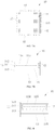
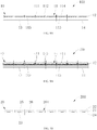
- two adjustment electrodes 12 are provided on each side of the house 11. In some embodiments, referring to FIG.
- adjustment electrodes 12 may also be provided on each side of the house 11 and extend along a direction substantially perpendicular to the common electrode layer 13.
- FIG. 7B four adjustment electrodes 12 may also be provided on each side of the house 11 and extend along a direction substantially parallel to the common electrode layer 13.
- the four adjustment electrodes 12 may have same width as shown in FIG. 7A or different widths as shown in FIG. 7B .
- a number of adjustment electrodes 12, for example, three or five may also be provided on each side of the house 11.
- only one adjustment electrode 12 may also be provided on each side of the house 11 to facilitate processing and manufacturing.
- adjustment electrodes 12 on sides of the house 11 can be located on an inner side surfaces of the house 11 and exposed to the first light-transmissive liquid 114 and the second light-transmissive liquid 115, so that when voltages are applied between the adjustment electrodes 12 and the common electrode layer 13, the first light-transmissive liquid 114 can be converged toward the adjustment electrodes 12.
- the adjustment electrodes 12 can be buried under the inner side surfaces of the house 11, i.e., make the adjustment electrodes 12 not in direct contact with the first light-transmissive liquid 114 and the second light-transmissive liquid 115 as shown in FIG. 3 .
- FIG. 8 adjustment electrodes 12 on sides of the house 11 can be located on an inner side surfaces of the house 11 and exposed to the first light-transmissive liquid 114 and the second light-transmissive liquid 115, so that when voltages are applied between the adjustment electrodes 12 and the common electrode layer 13, the first light-transmissive liquid 114 can be converged toward the adjustment electrodes 12.
- the adjustment electrodes 12 can be
- the light-concentrating plate 100 further includes a light-transmissive substrate 14.
- the common electrode layer 13 of each dimming unit 10 is located on the light-transmissive substrate 14.
- the common electrode layer 13 is formed on the light-transmissive substrate 14 first, then the insulating layer 113 is formed on the common electrode layer 13, then the conferdam 111 with adjustment electrodes 12 is formed, and then the light-transmissive layer 112 is located on the insulating layer 113, which facilitates making process as well as facilitates the plurality of dimming units 10 cooperatively to form an integrated plate-like structure.
- each dimming unit 10 may also be manufactured separately, and then fixed on the light-transmissive substrate 14.
- each of the plurality of dimming units 10 can include two common electrode layers 13. One of the two common electrode layers 13 is located on the insulating layer 113 and the other one of the two common electrode layers 13 is located on the light-transmissive layer 112. Both two common electrode layers 13 are insulated from the adjustment electrodes 12.
- the light-transmissive substrate 14 may be a glass layer, a transparent plastic layer, a transparent resin layer, or the like.
- the light-concentrating plate 100 may adjust the deflection direction and angle of the transmitted light, thereby can concentrate the light as well as achieve focusing.
- the light-concentrating plate may achieve light extraction with larger areas and angles and acquisition of more light, thereby improving the imaging quality.
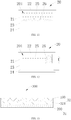
- the switch plate 200 includes a plurality of switch units 20 arranged in an array to facilitate arrangement.
- Each of the switch units 20 includes a dam 21, a light-transmissive electrode layer 22, an insulating transparent layer 23, and a light-transmissive conductive layer 24.
- the light-transmissive electrode layer 22 covers an end of the dam 21, and the insulating transparent layer 23 is provided at the other end of the dam 21.
- the light-transmissive conductive layer 24 is located on a side of the insulating transparent layer 23 facing away from the light-transmissive electrode layer 22.
- the dam 21, the light-transmissive electrode layer 22, and the insulating transparent layer 23 cooperatively form a sealed chamber 201 filled with a light-transmissive conductive liquid 25 and a light-reflective liquid 26.
- the light-transmissive conductive liquid 25 and the light-reflective liquid 26 are insoluble with each other. That is, the light-transmissive conductive liquid 25 is insoluble in the light-reflective liquid 26, and the light-reflective liquid 26 is also insoluble in the light-transmissive conductive liquid 25, so that an interface 116 is formed between the light-transmissive conductive liquid 25 and the light-reflective liquid 26.
- the light-transmissive conductive liquid 25 is a conductive liquid
- the light-reflective liquid 26 is a light-reflective and non-conductive liquid, so that light will be reflected when passing through the interface 116 between the light-transmissive conductive liquid 25 and the light-reflective liquid 26.
- Affinity between the insulating transparent layer 23 and the light-reflective liquid 26 is greater than affinity between the insulating transparent layer 23 and the light-transmissive conductive liquid 25.
- regions outside the light-reflective liquid 26 in the sealed house 11 may transmit light, and thus, the switch units 20 are light-transmissive and the switch units 20 are in an on state.
- the switch units 20 in a region on the switch plate 200 are in an on state, a corresponding region of the switch plate 200 is configured to form a light-transmissive structure.
- the whole switch plate 200 forms a light-transmissive plate.
- the dam 21 may be made of epoxy resin, plastic, or the like and formed on the insulating transparent layer 23.
- the light-transmissive conductive layer 24 may be an ITO layer.
- the light-transmissive conductive layer 24 may also be other transparent and conductive electrode layer, such as a ZnO-based transparent conductive film, a multi-component transparent conductive film, a high-mobility transparent conductive film, or the like.
- the light-transmissive electrode layer 22 may be an ITO layer.
- the light-transmissive electrode layer 22 may also be other transparent and conductive electrode layer, such as a ZnO-based transparent conductive film, a multi-component transparent conductive film, a high-mobility transparent conductive film, or the like.
- the light-reflective liquid 26 may be non-conductive light-reflective ink with low costs.
- the light-reflective liquid 26 may also be other light-reflective liquid 26.
- the insulating transparent layer 23 may be a lipophilic insulating layer.
- the insulating transparent layer 23 may be a lipophilic insulating layer such as plastic or resin.
- the plastic may be polytetrafluoroethylene, and of course, may also be other plastic.
- the light-transmissive conductive liquid 25 may be a light-transmissive and conductive liquid such as an aqueous solution or an acetic acid solution.
- an embodiment of the present disclosure further provides a light-concentrating display screen 300, which includes a transparent display panel 32, a reflective layer 31, and a light-concentrating plate 100 according to any one of the above embodiments.
- the reflective layer 31 is provided on a back surface of the transparent display panel 32, so that when the transparent display panel 32 displays an image, the reflective layer 31 may play a role of reflecting light, thereby improving brightness of displaying of the transparent display panel 32.
- the light-concentrating plate 100 is provided on the transparent display panel 32 to achieve light concentration.
- the reflective layer 31 includes a light-transmissive structure 310, and with a light-transmissive structure 310 so that the light-concentrating display screen 300 is used cooperatively with a shooting module to realize the under-screen shooting function.
- the amount of light concentration can be increased, and light concentration with large areas and angles can be achieved.
- the focusing can be performed via the light-concentrating plate 100.
- the light-concentrating display screen 300 according to the embodiment of the present disclosure uses the above-mentioned light-concentrating plate 100, which can not only realize image displaying but also perform light concentration.
- the light-concentrating plate 100 is provided on a front surface of the transparent display panel 32, so that the light-concentrating plate 100 directly concentrates light which then passes through the transparent display panel 32.
- the light-concentrating plate 100 may also be provided between the transparent display panel 32 and the reflective layer 31, and the light-concentrating plate 100 concentrates light via the transparent display panel 32.
- the transparent display panel 32 includes an OLED layer 321 for emitting light and displaying an image.
- the light-concentrating plate 100 is provided on a front surface of the OLED layer 321, and the reflective layer 31 is a switch plate 200 according to any one of the above embodiments.
- a plurality of switch units 20 of the switch plate 200 may constitute a light-transmissive structure 310 of the reflective layer 31.
- the reflective layer 31 may also define a through hole in which the switch plate 200 may be provided.
- the light-concentrating plate 100 may also be provided between the OLED layer 321 and the reflective layer 31.
- the reflective layer 31 may also be a structure such as a light-reflective film, a light-reflective plate or the like, and the reflective layer 31 may define a light-transmissive hole 311 to form the light-transmissive structure 310.
- the transparent display panel 32 includes a Micro LED layer 322 configured for emitting light and displaying an image.
- the light-concentrating plate 100 is provided between the Micro LED layer 322 and the reflective layer 31.
- the light-transmissive structure 310 of the reflective layer 31 includes the light-transmissive hole 311 defined by the reflective layer 31.
- the light-concentrating plate 100 may also be provided on a front surface of the Micro LED layer 322.
- the reflective layer 31 is a switch plate 200 according to any one of the foregoing embodiments, and then the plurality of switch units 20 of the switch plate 200 may constitute the light-transmissive structure 310 of the reflective layer 31.
- the transparent display panel 32 includes a liquid crystal plate 331 and an LED backlight plate 332 provided on a back surface of the liquid crystal plate 331.
- the LED backlight plate 332 is configured to provide backlight and to cooperate with the transparent display panel 32 to display images.
- the reflective layer 31 is a switch plate 200 according to any one of the foregoing embodiments, and then the plurality of switch units 20 of the switch plate 200 may constitute the light-transmissive structure 310 of the reflective layer 31. By using the structure, it can facilitate configuring the position of the shooting module.
- the reflective layer 31 may also define a through hole in which the switch plate 200 may be provided.
- the reflective layer 31 may also define a light-transmissive hole 311 to form the light-transmissive structure 310.
- a front surface of the liquid crystal plate 331 is provided with a color filter layer 35, so that the light-light-concentrating display screen 300 can display color image.
- the light-concentrating plate 100 is provided on a front surface of the color filter layer 35.
- the light-concentrating plate 100 may be disposed between the liquid crystal plate 331 and the color filter layer 35.
- the light-concentrating plate 100 may also be provided between the liquid crystal plate 331 and the LED backlight plate 332.
- the light-concentrating plate 100 may also be provided between the LED backlight plate 332 and the reflective layer 31.
- the light-concentrating plate 100 is provided on the front surface of the liquid crystal plate 331, and the reflective layer 31 is provided on the back surface of the LED backlight plate 332.
- Each house 11 is a color house 11 which transmits one of red light, blue light and green light. Colors of three adjacent houses 11 thereof are arranged in an RGB manner.
- the light-concentrating plate 100 may realize the function of a color filter, so that the light-concentrating display screen 300 can display color image.
- each house 11 of the light-concentrating plate 100 may also be a transparent structure, and thus the light-concentrating display screen 300 can display black-white image.
- each house 11 of the light-concentrating plate 100 may also be a single color, and thus the light-concentrating display screen 300 may display a single color image.
- the transparent display panel 32 includes a liquid crystal plate 331 and a light guide plate 333 provided on a back surface of the liquid crystal plate 331.
- the light guide plate 333 is configured to guide light to provide backlight for the liquid crystal plate 331.
- the reflective layer 31 is provided on a back surface of the light guide plate 333.
- a position of the light guide plate 333 corresponding to the light-transmissive structure 310 defines an through hole 3331.
- the light-concentrating plate 100 is provided on the liquid crystal plate 331, so that after the light-concentrating plate 100 concentrates light, the concentrated light may enter the light-transmissive structure 310 via the through hole 3331 of the light guide plate 333.
- the light-concentrating display screen 300 may realize light-concentrating, dimming, and focusing by screen; and may concentrate light with large areas, extract light at large angles, and improve light flux.
- the light-concentrating display screen 300 according to the embodiment of the present disclosure may be applied to devices for under-screen lighting, such as under-screen shooting and under-screen fingerprint.
- embodiments of the present disclosure further provide a mobile terminal 400.
- the mobile terminal 400 includes a camera module 41 and a light-concentrating display screen 300 according to any one of the above embodiments.
- the camera module 41 is provided at a corresponding position of the light-transmissive structure 310.
- the mobile terminal 400 according to the embodiments of the present disclosure by including the above-mentioned light-concentrating display screen 300, can have no opening or through hole on the screen and increase a screen ratio.
- the light-concentrating display screen 300 can be directly used for light concentrating and focusing, and the camera module 41 can obtain more light, thereby improving the shooting quality.
- the mobile terminal 400 can be a cell phone.
- the terminal 500 includes a plurality of camera modules 51 arranged to form an array and a light-concentrating display screen 300 according to any one of the above embodiments.
- the light-concentrating display screen 300 includes a transparent display panel 32, a reflective layer 31, and a light-concentrating plate 100.
- the reflective layer 31 defies a plurality of through holes and each of the through holes is provided with a switch plate 200.
- the light-concentrating plate 100 is divided in to a plurality of regions 102, and each of the plurality of regions 102 corresponds to one of the switch plates 200 and controlled to concentrate light to the corresponding switch plate 200.
- Each of the plurality of camera modules 51 is located to correspond to one of the switch plates 200.
- the terminal 500 can be a personal computer or a television.
Landscapes
- Physics & Mathematics (AREA)
- General Physics & Mathematics (AREA)
- Nonlinear Science (AREA)
- Optics & Photonics (AREA)
- Engineering & Computer Science (AREA)
- Multimedia (AREA)
- Signal Processing (AREA)
- Mathematical Physics (AREA)
- Chemical & Material Sciences (AREA)
- Crystallography & Structural Chemistry (AREA)
- Theoretical Computer Science (AREA)
- Electrochromic Elements, Electrophoresis, Or Variable Reflection Or Absorption Elements (AREA)
Abstract
Description
- The present disclosure relate to the field of optical technology, and more particularly to light-concentrating devices, light-concentrating display screens, and electric products.
- Current camera modules generally perform focusing and light concentration through lenses. For mobile terminals with limited positions for installation, such as smartphones and tablet computers, camera module structures are largely affected by lens light-concentrating angles and lens sizes. Especially for an under-screen camera module, the camera module has a deeper position, a smaller light extraction angle and a smaller amount of light extraction, which affects the shooting quality.
- A light-concentrating device is provided. The light-concentrating device comprises: a light-concentrating plate. The light-concentrating plate comprises a plurality of dimming units arranged in an array, and each of the plurality of dimming units comprises: a house, wherein the house comprises a first wall, a second wall opposite to the first wall, and a side wall connected to both the first wall and the second wall, and the house allows light to pass through at least from the first wall to the second wall; a first light-transmissive liquid filled in the house, wherein the first light-transmissive liquid is a conductive liquid; a first electrode layer located on the second wall, wherein the first electrode layer allows the light to pass through; and an adjustment electrode located on the side wall of the house, wherein the adjustment electrode is insulated from the first electrode layer.
- A light-concentrating display screen is provided. The light-concentrating display screen comprises a transparent display panel, a reflective layer located on the transparent display panel and comprising a light-transmissive structure, and a light-concentrating device comprising a light-concentrating plate located on the transparent display panel. The light-concentrating plate comprises a plurality of dimming units arranged in an array, and each of the plurality of dimming units comprises: a house, wherein the house comprises a first wall, a second wall opposite to the first wall, and a side wall connected to both the first wall and the second wall; and the house allows light to pass through at least from the first wall to the second wall; a first light-transmissive liquid filled in the house, wherein the first light-transmissive liquid is a conductive liquid; a first electrode layer located on the second wall, wherein the first electrode layer allows the light to pass through; and an adjustment electrode located on the side wall of the house, wherein the adjustment electrode is insulated from the first electrode layer.
- An electric product is provided. The electric product comprises a camera module and a light-concentrating display screen. The light-concentrating display screen comprises a transparent display panel, a reflective layer located on the transparent display panel and comprising a light-transmissive structure, and a light-concentrating device comprising a light-concentrating plate located on the transparent display panel; the camera module being located on a corresponding position of the light-transmissive structure. The light-concentrating plate comprises a plurality of dimming units arranged in an array, and each of the plurality of dimming units comprises: a house, wherein the house comprises a first wall, a second wall opposite to the first wall, and a side wall connected to both the first wall and the second wall; and the house allows light to pass through at least from the first wall to the second wall; a first light-transmissive liquid filled in the house, wherein the first light-transmissive liquid is a conductive liquid; a first electrode layer located on the second wall, wherein the first electrode layer allows the light to pass through; and an adjustment electrode located on the side wall of the house, wherein the adjustment electrode is insulated from the first electrode layer.
- The light-concentrating device of the present disclosure has following advantage. The voltages may be applied between the first electrode layer and the adjustment electrodes, so that the first light-transmissive liquid can be deflected and inclined in the house, thereby deflecting the light transmitted through the house. By changing the voltages between the adjustment electrodes and the first electrode layer, the deflection angle of the light can be changed, and thereby to achieve light concentration via cooperation between the plurality of dimming units.
- The light-concentrating display screen, by including the light-concentrating device above, can not only realize image displaying but also perform light concentration.
- The electric product, by including the above-mentioned light-concentrating display screen above, can have no opening or through hole on the screen and increase a screen ratio. Moreover, the light-concentrating display screen can be directly used for light concentrating and focusing, and the camera module can obtain more light, thereby improving the shooting quality.
- In order to illustrate the technical solution in the embodiment of the present disclosure more clearly, a brief description to the drawings needed in the embodiment or the prior art are given in the following. Obviously, the figures in the following description are only some embodiments of the present disclosure. For those skilled in the art, they can also obtain other figures according to these drawings and without any creative work.
-
FIG. 1 is a cross-sectional structural diagram of a light-concentrating plate according to one embodiment of the present disclosure. -
FIG. 2 is a structural diagram showing that a plurality of dimming units cooperates to adjust light in the light-concentrating plate ofFIG. 1 . -
FIG. 3 is a structural diagram showing that a single dimming unit adjusts light in the light-concentrating plate ofFIG. 1 . -
FIG. 4 is a structural diagram of a top view of dimming units in a light-concentrating plate according to one embodiment of the present disclosure. -
FIG. 5 is a structural diagram of a top view of dimming units in a light-concentrating plate according to one embodiment of the present disclosure. -
FIG. 6 is a structural diagram of a top view of dimming units in a light-concentrating plate according to one embodiment of the present disclosure. -
FIG. 7A is a cross-sectional structural diagram of dimming units in a light-concentrating plate according to one embodiment of the present disclosure. -
FIG. 7B is a cross-sectional structural diagram of dimming units in a light-concentrating plate according to one embodiment of the present disclosure. -
FIG. 8 is a cross-sectional structural diagram of a light-concentrating plate according to one embodiment of the present disclosure. -
FIG. 9A is a cross-sectional structural diagram of a light-concentrating plate according to one embodiment of the present disclosure. -
FIG. 9B is a cross-sectional structural diagram of a light-concentrating plate according to one embodiment of the present disclosure. -
FIG. 10 is a cross-sectional structural diagram of a switch plate according to an embodiment of the present disclosure. -
FIG. 11 is a cross-sectional structural diagram I of the switch unit ofFIG. 10 , in which no voltage is applied between a light-transmissive electrode layer and a light-transmissive conductive layer. -
FIG. 12 is a cross-sectional structural diagram II of the switch unit ofFIG. 11 , in which a voltage is applied between the light-transmissive electrode layer and the light-transmissive conductive layer. -
FIG. 13 is a structural diagram of a first type of light-concentrating display screen according to an embodiment of the present disclosure. -
FIG. 14 is a structural diagram of a second type of light-concentrating display screen according to an embodiment of the present disclosure. -
FIG. 15 is a structural diagram of a third type of light-concentrating display screen according to an embodiment of the present disclosure. -
FIG. 16 is a structural diagram of a fourth type of light-concentrating display screen according to an embodiment of the present disclosure. -
FIG. 17 is a structural diagram of a fifth type of light-concentrating display screen according to an embodiment of the present disclosure. -
FIG. 18 is a structural diagram of a sixth type of light-concentrating display screen according to an embodiment of the present disclosure. -
FIG. 19 is a structural diagram of a seventh type of light-concentrating display screen according to an embodiment of the present disclosure. -
FIG. 20 is a structural diagram of a mobile terminal according to an embodiment of the present disclosure. -
FIG. 21 is a partially cross-sectional structural diagram of the mobile terminal ofFIG. 20 . -
FIG. 22 is a structural diagram of a computer terminal according to an embodiment of the present disclosure. - In order to make the technical problems to be solved, the technical solutions and the advantage of the present disclosure clearer, the present disclosure will be further described in detail by accompanying the drawings and embodiments. It should be understood that the specific embodiments described herein are only used to interpret the present disclosure and are not used to limit the scope of the present disclosure.
- It should be noted that when a component is stated as "located on" or "disposed on" or "provided on" another component, it can be directly or indirectly in contact with another component. When a component is stated "connected to" another component, it can be directly connected to another component or indirectly connected to another component.
- In addition, the terms "first" and "second" are used for descriptive purposes only and cannot be understood as indicating or implying relative importance or implying the number of indicated technical features. Thus, a feature limited by "first" or "second" may explicitly or implicitly include one or more such features. In the description of this disclosure, "multiple" means two or more, unless otherwise defined. "Several" means one or more, unless otherwise defined.
- In the description of the present disclosure, it should be noted that unless it is specified and defined, the terms "installation", "connect to" and "connection" should be understood in a broad sense, for example, they can be fixed connection, detachable connection, or integrated connection; they can be mechanical connection, or electrical connection; they can be directly connection, or they can be indirectly connection through an intermediate media; they can be the internal connection between two components or the interaction between two components. For those of ordinary skill in the art, the specific meaning of the above terms in the present disclosure can be understood according to the specific situation.
- Referring to "one embodiment" or "an embodiment" throughout the specification means that specific features, structures or properties described in the embodiments are included in at least one embodiment of the present disclosure. Therefore, the phrases "in one embodiment" or "in some embodiments" or "in embodiment" appear in various parts of the specification, and not all references are the same embodiment. In addition, in one or more embodiments, specific features, structures, or characteristics may be combined in any suitable manner.
- Abbreviations employed in the present disclosure are as follows:
- LED: Light Emitting Diode.
- OLED: Organic Light-Emitting Diode.
- ITO: Indium tin oxide.
- CF: Color Filter.
- In one embodiment, a light-concentrating device is provided. The light-concentrating device comprises: a light-concentrating plate. The light-concentrating plate comprises a plurality of dimming units arranged in an array, and each of the plurality of dimming units comprises: a house, wherein the house comprises a first wall, a second wall opposite to the first wall, and a side wall connected to both the first wall and the second wall, and the house allows light to pass through at least from the first wall to the second wall; a first light-transmissive liquid filled in the house, wherein the first light-transmissive liquid is a conductive liquid; a first electrode layer located on the second wall, wherein the first electrode layer allows the light to pass through; and an adjustment electrode located on the side wall of the house, wherein the adjustment electrode is insulated from the first electrode layer.
- In one embodiment, the first wall is a light-transmissive layer, the second wall is an insulating layer, and the first electrode layer is located on a side of the insulating layer facing away from the first wall; and the plurality of dimming units share a common light-transmissive layer, a common insulating layer, and a common first electrode layer.
- In one embodiment, each of the plurality of dimming units further comprises a second light-transmissive liquid filled in the house, wherein the second light-transmissive liquid is a non-conductive liquid, and the first light-transmissive liquid and the second light-transmissive liquid are insoluble with each other; a first affinity between the second wall and the second light-transmissive liquid is different from a second affinity between the second wall and the first light-transmissive liquid.
- In one embodiment, the house comprises four side walls, and each of the four side walls are provided with a plurality of adjustment electrodes, and two adjacent of the plurality of adjustment electrodes are insulated from each other and located at intervals.
- In one embodiment, the plurality of adjustment electrodes extend along a direction substantially parallel to or perpendicular to the first electrode layer.
- In one embodiment, each of the plurality of dimming units further comprises a second electrode layer located on the first wall, and the second electrode layer allows the light to pass through.
- In one embodiment, the light-concentrating device further comprises a controller connected to the adjustment electrode and the first electrode layer and configured to apply a voltage between the adjustment electrode and the first electrode layer.
- In one embodiment, the house comprises a cofferdam, a light-transmissive layer located on an end of the cofferdam, and an insulating layer located on the other end of the cofferdam, a side of the cofferdam being provided with the adjustment electrode, and the common electrode layer being located on the insulating layer.
- In one embodiment, an affinity between the insulating layer and the second light-transmissive liquid is greater than an affinity between the insulating layer and the first light-transmissive liquid; or the insulating layer is provided with an affinity layer having a light-transmissive property, and an affinity between the affinity layer and the second light-transmissive liquid is greater than an affinity between the affinity layer and the first light-transmissive liquid.
- In one embodiment, light-transmissive layers of the plurality of dimming units are integrated.
- In one embodiment, insulating layers of the plurality of dimming units are integrated.
- In one embodiment, four sides of the house are provided with adjustment electrodes, respectively, and two adjacent adjustment electrodes thereof are insulated and located at intervals.
- In one embodiment, each side of the house is provided with a plurality of adjustment electrodes, and two adjacent adjustment electrodes thereof are insulated and located at intervals.
- In one embodiment, the light-concentrating plate further comprises a light-transmissive substrate, and the common electrode layer of each of the plurality of dimming units is located on the light-transmissive substrate.
- In one embodiment, a light-concentrating display screen is provided. The light-concentrating display screen comprises a transparent display panel, a reflective layer located on the transparent display panel and comprising a light-transmissive structure, and a light-concentrating device comprising a light-concentrating plate located on the transparent display panel. The light-concentrating plate comprises a plurality of dimming units arranged in an array, and each of the plurality of dimming units comprises: a house, wherein the house comprises a first wall, a second wall opposite to the first wall, and a side wall connected to both the first wall and the second wall; and the house allows light to pass through at least from the first wall to the second wall; a first light-transmissive liquid filled in the house, wherein the first light-transmissive liquid is a conductive liquid; a first electrode layer located on the second wall, wherein the first electrode layer allows the light to pass through; and an adjustment electrode located on the side wall of the house, wherein the adjustment electrode is insulated from the first electrode layer.
- In one embodiment, the first wall is a light-transmissive layer, the second wall is an insulating layer, and the first electrode layer is located on a side of the insulating layer facing away from the first wall; and the plurality of dimming units share a common light-transmissive layer, a common insulating layer, and a common first electrode layer.
- In one embodiment, each of the plurality of dimming units further comprises a second light-transmissive liquid filled in the house, wherein the second light-transmissive liquid is a non-conductive liquid, and the first light-transmissive liquid and the second light-transmissive liquid are insoluble with each other; a first affinity between the second wall and the second light-transmissive liquid is different from a second affinity between the second wall and the first light-transmissive liquid.
- In one embodiment, the house comprises four side walls, and each of the four side walls are provided with a plurality of adjustment electrodes, and two adjacent of the plurality of adjustment electrodes are insulated from each other and located at intervals.
- In one embodiment, the plurality of adjustment electrodes extend along a direction substantially parallel to or perpendicular to the first electrode layer.
- In one embodiment, each of the plurality of dimming units further comprises a second electrode layer located on the first wall, and the second electrode layer allows the light to pass through.
- In one embodiment, the light-concentrating device further comprises a controller connected to the adjustment electrode and the first electrode layer and configured to apply a voltage between the adjustment electrode and the first electrode layer.
- In one embodiment, the transparent display panel comprises a liquid crystal plate and a LED backlight plate; the house is a color house and allows only one of red light, blue light, and green light to pass through, and colors of three adjacent houses are arranged in an RGB manner.
- In one embodiment, the light-transmissive structure comprises a plurality of switch units, and each of the switch units comprises: a dam; a light-transmissive electrode layer located on an end of the dam; an insulating transparent layer located on the other end of the dam; and a light-transmissive conductive layer located on the insulating transparent layer, wherein the dam, the light-transmissive electrode layer and the insulating transparent layer cooperatively form a sealed chamber; and a light-transmissive conductive liquid and a light-reflective liquid filled in the sealed chamber, wherein the light-transmissive conductive liquid and the light-reflective liquid are insoluble with each other, the light-reflective liquid is a light-reflective and non-conductive liquid, and an affinity between the insulating transparent layer and the light-reflective liquid is greater than an affinity between the insulating transparent layer and the light-transmissive conductive liquid.
- In one embodiment, the transparent display panel comprises an OLED layer or a Micro LED layer.
- In one embodiment, the light-concentrating plate is provided on a front surface of the transparent display panel; or the light-concentrating plate is located between the transparent display panel and the reflective layer.
- In one embodiment, the transparent display panel comprises a liquid crystal plate and an LED backlight plate located on a back face of the liquid crystal plate.
- In one embodiment, the light-concentrating plate is located on a front surface of the liquid crystal plate; or the light-concentrating plate is located between the LED backlight plate and the reflective layer.
- In one embodiment, the light-concentrating plate is located on the front surface of the liquid crystal plate, and each house is a color house that transmits one of red light, blue light, and green light, colors of three adjacent houses thereof being arranged in an RGB manner; or, the front surface of the liquid crystal plate being provided with a color filter layer.
- In one embodiment, at least one end of the house exhibits red light, blue light or green light; or/and, the first light-transmissive liquid exhibits red light, blue light or green light; or/and, the second light-transmissive liquid exhibits red light, blue light or green light.
- In one embodiment, the light-transmissive structure comprises a light-transmissive hole defined by the reflective layer.
- In one embodiment, the light-transmissive structure comprises a switch plate, the switch plate comprises a plurality of switch units, each of the switch units comprises a dam, a light-transmissive electrode layer located on an end of the dam, an insulating transparent layer located on the other end of the dam, and a light-transmissive conductive layer located on the insulating transparent layer, the light-transmissive conductive layer is located on a side of the insulating transparent layer facing away from the light-transmissive electrode layer, the dam, the light-transmissive electrode layer and the insulating transparent layer cooperatively form a sealed chamber, the sealed chamber is filled with a light-transmissive conductive liquid and a light-reflective liquid insoluble with each other, the light-reflective liquid is a light-reflective and non-conductive liquid, an affinity between the insulating transparent layer and the light-reflective liquid is greater than an affinity between the insulating transparent layer and the light-transmissive conductive liquid.
- In one embodiment, the light-reflective layer defines a through hole, the switch plate is located in the through hole; or, the reflective layer is functioned as the switch plate, and the plurality of switch units of the reflective layer constituting the light-transmissive structure.
- In one embodiment, an electric product is provided. The electric product comprises a camera module and a light-concentrating display screen. The light-concentrating display screen comprises a transparent display panel, a reflective layer located on the transparent display panel and comprising a light-transmissive structure, and a light-concentrating device comprising a light-concentrating plate located on the transparent display panel; the camera module being located on a corresponding position of the light-transmissive structure. The light-concentrating plate comprises a plurality of dimming units arranged in an array, and each of the plurality of dimming units comprises: a house, wherein the house comprises a first wall, a second wall opposite to the first wall, and a side wall connected to both the first wall and the second wall; and the house allows light to pass through at least from the first wall to the second wall; a first light-transmissive liquid filled in the house, wherein the first light-transmissive liquid is a conductive liquid; a first electrode layer located on the second wall, wherein the first electrode layer allows the light to pass through; and an adjustment electrode located on the side wall of the house, wherein the adjustment electrode is insulated from the first electrode layer.
- In one embodiment, the first wall is a light-transmissive layer, the second wall is an insulating layer, and the first electrode layer is located on a side of the insulating layer facing away from the first wall; and the plurality of dimming units share a common light-transmissive layer, a common insulating layer, and a common first electrode lay.
- In one embodiment, the house comprises four side walls, and each of the four side walls are provided with a plurality of adjustment electrodes, and two adjacent of the plurality of adjustment electrodes are insulated from each other and located at intervals.
- In one embodiment, each of the plurality of dimming units further comprises a second light-transmissive liquid filled in the house, wherein the second light-transmissive liquid is a non-conductive liquid, and the first light-transmissive liquid and the second light-transmissive liquid are insoluble with each other.
- The above one or more technical solutions in the embodiment of the present disclosure have at least one of the following technical effects:
- The light-concentrating plate according to the embodiments of the present disclosure is provided with a plurality of dimming units. Two ends of the house of each of the dimming units transmit light, and the house is filled with insoluble first light-transmissive liquid and second light-transmissive liquid. Then, light may be refracted when passing through the interface between the first light-transmissive liquid and the second light-transmissive liquid. Adjustment electrodes are provided on sides of the house, and a common electrode layer is provided at an end of the house. The voltages may be applied between the common electrode layer and the adjustment electrodes on the sides of the house, so that the first light-transmissive liquid and the second light-transmissive liquid can be to deflected and inclined in the house, thereby deflecting the light transmitted through the house. By changing the voltages between the adjustment electrodes on the sides of the house and the common electrode layer, the deflection angle of the light can be changed, and thereby to achieve light concentration via cooperation between the plurality of dimming units.
- The light-concentrating display screen according to the embodiment of the present disclosure uses the above-mentioned light-concentrating plate, which can not only realize image displaying but also perform light concentration.
- The mobile terminal according to the embodiments of the present disclosure, by including the above-mentioned light-concentrating display screen, can have no opening or through hole on the screen and increase a screen ratio. Moreover, the light-concentrating display screen can be directly used for light concentrating and focusing, and the camera module can obtain more light, thereby improving the shooting quality.
- Referring
FIGS. 1 to 3 , a light-concentratingdevice 600 provided by the present disclosure will be hereby described. The light-concentratingdevice 600 includes a light-concentratingplate 100 and acontroller 60 electrically connected to the light-concentratingplate 100. The light-concentratingplate 100 includes a plurality of dimmingunits 10 arranged in an array. Each of the dimmingunits 10 constitutes a light-concentrating pixel point of the light-concentratingplate 100, and the structure is convenient for arrangement. - Each of the dimming
units 10 includes ahouse 11 of which at least two ends transmit light. Light may pass through thehouse 11, that is, light may enter from one end of thehouse 11 and be get out of thehouse 11 from the other end. Thehouse 11 is filled with a first light-transmissive liquid 114 and a second light-transmissive liquid 115. The first light-transmissive liquid 114 and the second light-transmissive liquid 115 are insoluble with each other, namely, the first light-transmissive liquid 114 is insoluble in the second light-transmissive liquid 115, and the second light-transmissive liquid 115 is also insoluble in the first light-transmissive liquid 114, so that aninterface 116 is formed between the first light-transmissive liquid 114 and the second light-transmissive liquid 115. The first light-transmissive liquid 114 is a conductive liquid, and the second light-transmissive liquid 115 is a non-conductive liquid. The first light-transmissive liquid 114 is located at one end of thehouse 11 and the second light-transmissive liquid 115 is located at the other end of thehouse 11, so that the light may be refracted when passing through theinterface 116 between the light-transmissive liquid 114 and the second light-transmissive liquid 115. An end of thehouse 11 adjacent to the second light-transmissive liquid 115 is provided with acommon electrode layer 13, and sides of thehouse 11 are provided withadjustment electrodes 12. Each of theadjustment electrodes 12 is located to be insulated from thecommon electrode layer 13 which is a light-transmissive layer. - The
controller 60 can be a micro processor and electrically connected to theadjustment electrodes 12 and thecommon electrode layer 13 and configured to apply a voltage between theadjustment electrodes 12 and thecommon electrode layer 13. In one embodiment, thecontroller 60 is configured to apply a voltage between each of theadjustment electrodes 12 and thecommon electrode layer 13. The voltage between one of theadjustment electrodes 12 and thecommon electrode layer 13 can be same or different from the voltage between another one of theadjustment electrodes 12 and thecommon electrode layer 13. - Referring
FIGS. 2 and 3 , for convenience of description, two sides of thehouse 11 are defined as afirst side 117 and asecond side 118. In one embodiment, the two sides of thehouse 11 are each provided with anadjustment electrode 12, and theadjustment electrodes 12 on the two sides of thehouse 11 are defined as afirst electrode 121 and asecond electrode 122. Voltages are applied to theadjustment electrodes 12 on the two sides of thehouse 11. The voltages applied to theadjustment electrodes 12 are voltages relative to thecommon electrode layer 13, that is, a voltage V1 is applied between thefirst electrode 121 and thecommon electrode layer 13, and a voltage V2 is applied between thesecond electrode 122 and thecommon electrode layer 13. - When V1=V2=0, the
interface 116 between the first light-transmissive liquid 114 and the second light-transmissive liquid 115 is planar. - When V1=V2, and both V1 and V2 are greater than zero, since the first light-
transmissive liquid 114 is a conductive liquid, the first light-transmissive liquid 114 will converge toward each of theadjustment electrodes 12, that is, the first light-transmissive liquid 114 will converge toward thefirst electrode 121 and thesecond electrode 122, theinterface 116 is formed between the first light-transmissive liquid 114 and the second light-transmissive liquid 115, theinterface 116 is a curved surface with a center portion protruding in a direction away from thecommon electrode layer 13, and a position of theinterface 116 closer to theadjustment electrodes 12 is more inclined toward a direction adjacent to thecommon electrode layer 13, so that the light passing through theinterface 116 are deflected. - When V1> V2, since the first light-
transmissive liquid 114 is a conductive liquid, the first light-transmissive liquid 114 will converge toward theadjustment electrodes 12, and theinterface 116 is formed between the first light-transmissive liquid 114 and the second light-transmissive liquid 115, theinterface 116 is a curved surface with a center portion protruding in a direction away from thecommon electrode layer 13, and a position of theinterface 116 closer to theadjustment electrodes 12 is more inclined toward a direction adjacent to thecommon electrode layer 13. Moreover, intensity of an electric field at thefirst electrode 121 will be greater than that at thesecond electrode 122, and then thefirst side 117 of thehouse 11 will gather more first light-transmissive liquid 114 than thesecond side 118 of thehouse 11, so that a distance between a position of theinterface 116 adjacent to thefirst side 117 of thehouse 11 and thecommon electrode layer 13 will be smaller than a distance between a position of theinterface 116 adjacent to thesecond side 118 of thehouse 11 and thecommon electrode layer 13, thereby aslo making the light passing through theinterface 116 be deflected. - When the voltage V1 is applied between only the
adjustment electrode 12 on a single side of thehouse 11 and thecommon electrode layer 13, i.e., when the voltage V1 is applied between only thefirst electrode 121 and thecommon electrode layer 13, the first light-transmissive liquid 114 will converge toward a side of thefirst electrode 121, so that theinterface 116 formed between the first light-transmissive liquid 114 and the second light-transmissive liquid 115 is inclined. Moreover, a distance between a side of theinterface 116 adjacent to thefirst electrode 121 and thecommon electrode layer 13 is smaller than a distance between the other side of theinterface 116 away from thefirst electrode 121 and thecommon electrode layer 13, so that the light passing through theinterface 116 are deflected. Furthermore, as V1 increases, the inclination of theinterface 116 relative to thecommon electrode layer 13 will increase, thereby adjusting a deflection angle of the light passing through thehouse 11. - When the voltage V2 is applied between only the
adjustment electrode 12 on the other single side of thehouse 11 and thecommon electrode layer 13, i.e., when the voltage V2 is applied between only thesecond electrode 122 and thecommon electrode layer 13, the first light-transmissive liquid 114 will converge toward a side of thesecond electrode 122, so that theinterface 116 formed between the first light-transmissive liquid 114 and the second light-transmissive liquid 115 is inclined. Moreover, a distance between a side of theinterface 116 adjacent to thesecond electrode 122 and thecommon electrode layer 13 is smaller than a distance between the other side of theinterface 116 away from thesecond electrode 122 and thecommon electrode layer 13, so that the light passing through theinterface 116 are deflected. Furthermore, as V2 increases, the inclination of theinterface 116 relative to thecommon electrode layer 13 will increase, thereby adjusting a deflection angle of the light passing through thehouse 11. - The two cases of applying the voltage V1 between the
first electrode 121 and thecommon electrode layer 13 and applying the voltage V2 between thesecond electrode 122 and thecommon electrode layer 13 may cause the light at theinterface 116 to be deflected in different directions. When thefirst electrode 121 and thesecond electrode 122 are located on two opposite sides of thehouse 11, the light at theinterface 116 will be deflected in opposite directions. Therefore, when different combined voltages are applied between theadjustment electrodes 12 of the dimmingunits 10 and thecommon electrode layer 13, the deflection of the light passing through the dimmingunits 10 can be controlled. Furthermore, when different combined voltages are applied between theadjustment electrodes 12 of the plurality of dimmingunits 10 and thecommon electrode layer 13, the light passing through the dimmingunits 10 can be converged. Furthermore, by adjusting magnitudes of the voltages applied to each of the dimmingunits 10, the focusing of the light can be achieved. - In one embodiment, the
house 11 can be filled only with the first light-transmissive liquid 114, and the second light-transmissive liquid 115 can be replaced by gas such as air. Theinterface 116 can be the interface between the first light-transmissive liquid 114 and air. - Of course, in some embodiments, the
adjustment electrodes 12 may also be provided on only one side of thehouse 11. During manufacturing, a position light-concentrating center of the light-concentratingplate 100 is first determined, and theadjustment electrodes 12 of all thehouses 11 equidistant from the light-concentrating center are located on a side of thecorresponding house 11 adjacent to the light-concentrating center, whereby the converging of light may also be achieved. - The light-concentrating
plate 100 according to the embodiments of the present disclosure is provided with a plurality of dimmingunits 10. Two ends of thehouse 11 of each of the dimmingunits 10 transmit light, and thehouse 11 is filled with insoluble first light-transmissive liquid 114 and second light-transmissive liquid 115. Then, light may be refracted when passing through theinterface 116 between the first light-transmissive liquid 114 and the second light-transmissive liquid 115.Adjustment electrodes 12 are provided on sides of thehouse 11, and acommon electrode layer 13 is provided at an end of thehouse 11. The voltages may be applied between thecommon electrode layer 13 and theadjustment electrodes 12 on the sides of thehouse 11, so that the first light-transmissive liquid 114 and the second light-transmissive liquid 115 can be to deflected and inclined in thehouse 11, thereby deflecting the light transmitted through thehouse 11. By changing the voltages between theadjustment electrodes 12 on the sides of thehouse 11 and thecommon electrode layer 13, the deflection angle of the light can be changed, and thereby to achieve light concentration via cooperation between the plurality of dimmingunits 10. - In one embodiment, the
house 11 includes acofferdam 111, a light-transmissive layer 112, and an insulatinglayer 113. The light-transmissive layer 112 is located an end of thecofferdam 111, and the insulatinglayer 113 is located at the other end of thecofferdam 111. That is, thecofferdam 111, the light-transmissive layer 112, and the insulatinglayer 113 cooperatively form thehouse 11, so as to facilitate processing and manufacturing. Theadjustment electrodes 12 are provided on sides of thecofferdam 111, and are supported via thecofferdam 111. Thecommon electrode layer 13 is provided on the insulatinglayer 113, and is supported via the insulatinglayer 113. - In one embodiment, referring to
FIG. 1 , the light-transmissive layers 112 of the plurality of dimmingunits 10 are integrated, that is, a whole light-transmissive sheet is directly divided into plurality of regions each serving as the light-transmissive layers 112 of the dimmingunits 10, so that to facilitate processing and manufacturing. Of course, in some embodiments, the light-transmissive layers 112 may be provided independently. The plurality of dimmingunits 10 may be adhesively connected, or the plurality of dimmingunits 10 may be fabricated on a transparent support plate or cover plate. In some embodiments, the light-transmissive layers 112 may also be disposed on a single plate, so as to facilitate connection of the plurality of dimmingunits 10 and to facilitate manufacturing. - In one embodiment, the
cofferdam 111 is made of a light-transmissive material, so that light may enter thehouse 11 through thecofferdam 111, and will be refracted to converge, when passing theinterface 116 between the first light-transmissive liquid 114 and the second light-transmissive liquid 115. This solution may achieve the effect of gathering more light to implement lighting. Of course, in some embodiments, thecofferdam 111 may also be opaque, and as such, only two ends of eachhouse 11 are light-transmissive. - In one embodiment, referring to
FIG. 1 , the insulatinglayers 113 of the plurality of dimmingunits 10 are integrated, that is, a whole insulating sheet is directly divided into a plurality of regions each serving as the insulatinglayers 113 of the dimmingunits 10 to facilitate processing and manufacturing. Of course, in some embodiments, the insulatinglayers 113 may be provided independently; and the plurality of dimmingunits 10 may be adhesively connected, or the plurality of dimmingunits 10 may be fabricated on a transparent support plate or cover plate. In some embodiments, the insulatinglayers 113 may also be provided on a plate, so as to facilitate connection of the plurality of dimmingunits 10 and to facilitate manufacturing. - In one embodiment, referring
FIGS. 2 and 3 , the affinity between the insulatinglayer 113 and the second light-transmissive liquid 115 is greater than the affinity between the insulatinglayer 113 and the first light-transmissive liquid 114, so that the second light-transmissive liquid 115 may adhere to the insulatinglayer 113. Thus, the first light-transmissive liquid 114 and the second light-transmissive liquid 115 are located at two opposite ends of thehouse 11, thereby facilitating positioning the second light-transmissive liquid 115. - In some embodiments, an affinity layer having a light-transmissive property may also be provided on the insulating
layer 113, and the affinity between the affinity layer and the second light-transmissive liquid 115 is greater than the affinity between the affinity layer and the first light-transmissive liquid 114. - In one embodiment, each
house 11 is acolor house 11, so that thehouse 11 can selectively transmits light of a corresponding color. For example, when thehouse 11 is red, thehouse 11 may transmit red light; when thehouse 11 is green, thehouse 11 may transmit green light, and the like. By providing thehouse 11 with a color, the filtering of light can be achieved, namely, the light can be filted by the dimmingunits 10. - In one embodiment, the first light-
transmissive liquid 114 filled in thehouse 11 may be a color liquid having a single color, so that thehouse 11 as a whole exhibits a corresponding color. Of course, if thehouse 11 is required to exhibit a color, the first light-transmissive liquid 114 therein may be configured to be a liquid having the required color. - In one embodiment, the second light-
transmissive liquid 115 filled in thehouse 11 may be a color liquid having a single color, so that thehouse 11 as a whole exhibits a corresponding color. Of course, if thehouse 11 is required to exhibit a color, the second light-transmissive liquid 115 therein may be configured to be a liquid having the required color. - In one embodiment, both the first light-
transmissive liquid 114 and the second light-transmissive liquid 115 in thehouse 11 may be configured to be colored liquids having the same color, so that thehouse 11 as a whole exhibits a corresponding color. Of course, if thehouse 11 is required to exhibit a color, both the first light-transmissive liquid 114 and the second light-transmissive liquid 115 therein may be configured to be liquids having the required same color. - Of course, in one embodiment, if the
house 11 is required to exhibit a color, an end of thehouse 11 may be configured as a light-transmissive surface having the required color, or the other end of thehouse 11 may be configured as a light-transmissive surface having the required color. In one embodiment, both two opposite ends of thehouse 11 may be configured as light-transmissive surfaces having the required color. - Of course, in one embodiment, if the
house 11 is required to exhibit a color, one or more than one of the two ends of thehouse 11, the first light-transmissive liquid 114 and the second light-transmissive liquid 115 may be configured to have the required color. - In some embodiments, the color of each
house 11 is one of red light, blue light, and green light. For example, at least one end of thehouse 11 exhibits red light, blue light, or green light; and/or the first light-transmissive liquid 114 exhibits red light, blue light or green light; and/or the second light-transmissive liquid 115 exhibits red light, blue light or green light. Colors of threeadjacent houses 11 thereof are arranged in RGB, where R is Red, G is Green, and B is Blue. Accordingly, the light-concentratingplate 100 may be configured to function as a color filter (CF). - In one embodiment, the second light-
transmissive liquid 115 may be non-conductive ink with low costs. Of course, the second light-transmissive liquid 115 may also be other light-transmissive liquid. - In one embodiment, when the second light-
transmissive liquid 115 is ink, the insulatinglayer 113 may be a insulating transparent layer. For example, the insulating transparent layer may be a lipophilic insulating layer such as plastic or resin. The plastic may be polytetrafluoroethylene, and of course, may also be other plastic. - In one embodiment, the first light-
transmissive liquid 114 may be a light-transmissive and conductive liquid such as an aqueous solution or an acetic acid solution. - In one embodiment, the light-
transmissive layer 112 may be a glass layer, a transparent plastic layer, a transparent resin layer, or the like. - In one embodiment, the
common electrode layer 13 may be an ITO layer. Of course, thecommon electrode layer 13 may also be other transparent and conductive electrode layer, such as a ZnO-based transparent conductive film, a multi-component transparent conductive film, a high-mobility transparent conductive film, or the like. - In one embodiment, the
cofferdam 111 may be made of epoxy resin, plastic, or the like and formed on the insulating transparent layer. - In one embodiment, referring to
FIG. 4 , oneadjustment electrode 12 is provided on one side of thehouse 11 and the other oneadjustment electrode 12 is provided on the other one side of thehouse 11 adjacent to the one side of thehouse 11, so that a voltage is independently applied between one of theadjustment electrodes 12 and acommon electrode layer 13 to adjust light passing through thehouse 11 to be deflected toward a side of thehouse 11. When voltages are applied concurrently between the twoadjacent adjustment electrodes 12 and thecommon electrode layer 13, the first light-transmissive liquid 114 will converge toward the twoadjustment electrodes 12; and intensity of an electric field adjacent to the twoadjustment electrodes 12 is greater, and there will be more first light-transmissive liquid 114 concentrated at position adjacent to theadjustment electrodes 12. Thus, aninterface 116 formed between the first light-transmissive liquid 114 and the second light-transmissive liquid 115 will be inclined along a diagonal line of thehouse 11, and the diagonal line is a diagonal line corresponding to one end of the eachadjustment electrode 12 away from theother adjustment electrode 12; and a distance between a corner of theinterface 116 adjacent to the twoadjustment electrodes 12 and thecommon electrode layer 13 is smaller than a distance between another opposite corner of theinterface 116 and thecommon electrode layer 13. This structure may make it easier to adjust theinterface 116 between the first light-transmissive liquid 114 and the second light-transmissive liquid 115 in thehouse 11, thereby adjusting the deflection direction and angle of the light passing through the dimmingunits 10. - In one embodiment, referring to
FIG. 5 , each of four sides of thehouse 11 is provided with anadjustment electrode 12, and twoadjacent adjustment electrodes 12 thereof are configured to be insulated and located at intervals. This structure may make it easier to control the shape and inclination angle of theinterface 116 between the first light-transmissive liquid 114 and the second light-transmissive liquid 115, thereby facilitating controlling the deflection direction and angle of the light passing the dimmingunits 10. In addition, in this structure, the dimmingunits 10 may have a same structure on each of the sides, which facilitates arrangement and processing and manufacturing. - In one embodiment, referring to
FIG. 6 , a plurality ofadjustment electrodes 12 are provided on each side of thehouse 11, and twoadjacent adjustment electrodes 12 thereof are configured to be insulated and located at intervals. By providing the plurality ofadjustment electrodes 12 on each side of thehouse 11, the shape of theinterface 116 between the first light-transmissive liquid 114 and the second light-transmissive liquid 115 can be further controlled, which facilitates control of the deflection directions and angles of the light passing through each of the dimming units, thereby achieving focusing. In one embodiment, twoadjustment electrodes 12 are provided on each side of thehouse 11. In some embodiments, referring toFIG. 7A , fouradjustment electrodes 12 may also be provided on each side of thehouse 11 and extend along a direction substantially perpendicular to thecommon electrode layer 13.FIG. 7B , fouradjustment electrodes 12 may also be provided on each side of thehouse 11 and extend along a direction substantially parallel to thecommon electrode layer 13. The fouradjustment electrodes 12 may have same width as shown inFIG. 7A or different widths as shown inFIG. 7B . In some other embodiments, a number ofadjustment electrodes 12, for example, three or five, may also be provided on each side of thehouse 11. Of course, in one embodiment, referring toFIG. 5 , only oneadjustment electrode 12 may also be provided on each side of thehouse 11 to facilitate processing and manufacturing. - In one embodiment, referring to
FIG. 8 ,adjustment electrodes 12 on sides of thehouse 11 can be located on an inner side surfaces of thehouse 11 and exposed to the first light-transmissive liquid 114 and the second light-transmissive liquid 115, so that when voltages are applied between theadjustment electrodes 12 and thecommon electrode layer 13, the first light-transmissive liquid 114 can be converged toward theadjustment electrodes 12. In one embodiment, theadjustment electrodes 12 can be buried under the inner side surfaces of thehouse 11, i.e., make theadjustment electrodes 12 not in direct contact with the first light-transmissive liquid 114 and the second light-transmissive liquid 115 as shown inFIG. 3 . In one embodiment, referring toFIG. 9A , the light-concentratingplate 100 further includes a light-transmissive substrate 14. Thecommon electrode layer 13 of eachdimming unit 10 is located on the light-transmissive substrate 14. At the time of making the structure, thecommon electrode layer 13 is formed on the light-transmissive substrate 14 first, then the insulatinglayer 113 is formed on thecommon electrode layer 13, then theconferdam 111 withadjustment electrodes 12 is formed, and then the light-transmissive layer 112 is located on the insulatinglayer 113, which facilitates making process as well as facilitates the plurality of dimmingunits 10 cooperatively to form an integrated plate-like structure. Of course, in some embodiments, eachdimming unit 10 may also be manufactured separately, and then fixed on the light-transmissive substrate 14. - In one embodiment, referring to
FIG. 9B , each of the plurality of dimmingunits 10 can include two common electrode layers 13. One of the two common electrode layers 13 is located on the insulatinglayer 113 and the other one of the two common electrode layers 13 is located on the light-transmissive layer 112. Both two common electrode layers 13 are insulated from theadjustment electrodes 12. - In one embodiment, the light-
transmissive substrate 14 may be a glass layer, a transparent plastic layer, a transparent resin layer, or the like. - The light-concentrating
plate 100 according to the embodiments of the present disclosure may adjust the deflection direction and angle of the transmitted light, thereby can concentrate the light as well as achieve focusing. When used in cooperation with an image sensor, the light-concentrating plate may achieve light extraction with larger areas and angles and acquisition of more light, thereby improving the imaging quality. - Referring
FIGS. 10 to 12 , embodiments of the present disclosure further provide aswitch plate 200. Theswitch plate 200 includes a plurality ofswitch units 20 arranged in an array to facilitate arrangement. Each of theswitch units 20 includes adam 21, a light-transmissive electrode layer 22, an insulatingtransparent layer 23, and a light-transmissiveconductive layer 24. The light-transmissive electrode layer 22 covers an end of thedam 21, and the insulatingtransparent layer 23 is provided at the other end of thedam 21. The light-transmissiveconductive layer 24 is located on a side of the insulatingtransparent layer 23 facing away from the light-transmissive electrode layer 22. Thedam 21, the light-transmissive electrode layer 22, and the insulatingtransparent layer 23 cooperatively form a sealedchamber 201 filled with a light-transmissiveconductive liquid 25 and a light-reflective liquid 26. The light-transmissiveconductive liquid 25 and the light-reflective liquid 26 are insoluble with each other. That is, the light-transmissiveconductive liquid 25 is insoluble in the light-reflective liquid 26, and the light-reflective liquid 26 is also insoluble in the light-transmissiveconductive liquid 25, so that aninterface 116 is formed between the light-transmissiveconductive liquid 25 and the light-reflective liquid 26. The light-transmissiveconductive liquid 25 is a conductive liquid, and the light-reflective liquid 26 is a light-reflective and non-conductive liquid, so that light will be reflected when passing through theinterface 116 between the light-transmissiveconductive liquid 25 and the light-reflective liquid 26. Affinity between the insulatingtransparent layer 23 and the light-reflective liquid 26 is greater than affinity between the insulatingtransparent layer 23 and the light-transmissiveconductive liquid 25. - Referring
FIGS. 11 and 12 , when no voltage is applied between the light-transmissive electrode layer 22 and the light-transmissiveconductive layer 24, since affinity between the insulatingtransparent layer 23 and the light-reflective liquid 26 is greater than affinity between the insulatingtransparent layer 23 and the light-transmissiveconductive liquid 25, the light-reflective liquid 26 will be located on and cover entire the insulatingtransparent layer 23. Thus, when irradiating on the light-reflective liquid 26, light will undergo reflection to form a light-reflective structure, thus theswitch units 20 are in an off state. When theswitch units 20 on theswitch plate 200 are in the off state, theswitch plate 200 is configured to form a light-reflective plate. - Referring
FIGS. 11 and 12 , when a voltage U is applied between the light-transmissive electrode layer 22 and the light-transmissiveconductive layer 24, since the light-transmissive electrode layer 22 is located one end of the other end of the sealedhouse 11, an electric field will be formed in the sealedhouse 11. Due to the electrowetting effect, a contact angle of the light-reflective liquid 26 decreases and the light-reflective liquid 26 shrinks. Meanwhile, since the light-transmissiveconductive liquid 25 is a conductive liquid and flows under the action of the electric field in the sealedhouse 11, the light-transmissive conductive liquid 25 will squeeze the light-reflective liquid 26 to move to sides of the sealedhouse 11, so that the light-reflective liquid 26 forms a small droplet. Thus, regions outside the light-reflective liquid 26 in the sealedhouse 11 may transmit light, and thus, theswitch units 20 are light-transmissive and theswitch units 20 are in an on state. When theswitch units 20 in a region on theswitch plate 200 are in an on state, a corresponding region of theswitch plate 200 is configured to form a light-transmissive structure. When all theswitch units 20 of theswitch plate 200 are in an on state, thewhole switch plate 200 forms a light-transmissive plate. - In one embodiment, the
dam 21 may be made of epoxy resin, plastic, or the like and formed on the insulatingtransparent layer 23. - In one embodiment, the light-transmissive
conductive layer 24 may be an ITO layer. Of course, the light-transmissiveconductive layer 24 may also be other transparent and conductive electrode layer, such as a ZnO-based transparent conductive film, a multi-component transparent conductive film, a high-mobility transparent conductive film, or the like. - In one embodiment, the light-
transmissive electrode layer 22 may be an ITO layer. Of course, the light-transmissive electrode layer 22 may also be other transparent and conductive electrode layer, such as a ZnO-based transparent conductive film, a multi-component transparent conductive film, a high-mobility transparent conductive film, or the like. - In one embodiment, the light-
reflective liquid 26 may be non-conductive light-reflective ink with low costs. Of course, the light-reflective liquid 26 may also be other light-reflective liquid 26. - In one embodiment, when the light-
reflective liquid 26 is ink, the insulatingtransparent layer 23 may be a lipophilic insulating layer. For example, the insulatingtransparent layer 23 may be a lipophilic insulating layer such as plastic or resin. The plastic may be polytetrafluoroethylene, and of course, may also be other plastic. - In one embodiment, the light-transmissive conductive liquid 25 may be a light-transmissive and conductive liquid such as an aqueous solution or an acetic acid solution.
- Referring to
FIG. 13 , an embodiment of the present disclosure further provides a light-concentratingdisplay screen 300, which includes atransparent display panel 32, areflective layer 31, and a light-concentratingplate 100 according to any one of the above embodiments. Thereflective layer 31 is provided on a back surface of thetransparent display panel 32, so that when thetransparent display panel 32 displays an image, thereflective layer 31 may play a role of reflecting light, thereby improving brightness of displaying of thetransparent display panel 32. The light-concentratingplate 100 is provided on thetransparent display panel 32 to achieve light concentration. Thereflective layer 31 includes a light-transmissive structure 310, and with a light-transmissive structure 310 so that the light-concentratingdisplay screen 300 is used cooperatively with a shooting module to realize the under-screen shooting function. Moreover, the amount of light concentration can be increased, and light concentration with large areas and angles can be achieved. The focusing can be performed via the light-concentratingplate 100. The light-concentratingdisplay screen 300 according to the embodiment of the present disclosure uses the above-mentioned light-concentratingplate 100, which can not only realize image displaying but also perform light concentration. - In one embodiment, the light-concentrating
plate 100 is provided on a front surface of thetransparent display panel 32, so that the light-concentratingplate 100 directly concentrates light which then passes through thetransparent display panel 32. In some other embodiments, the light-concentratingplate 100 may also be provided between thetransparent display panel 32 and thereflective layer 31, and the light-concentratingplate 100 concentrates light via thetransparent display panel 32. - In one embodiment, referring to
FIG. 13 . In one embodiment, thetransparent display panel 32 includes anOLED layer 321 for emitting light and displaying an image. The light-concentratingplate 100 is provided on a front surface of theOLED layer 321, and thereflective layer 31 is aswitch plate 200 according to any one of the above embodiments. Thus, a plurality ofswitch units 20 of theswitch plate 200 may constitute a light-transmissive structure 310 of thereflective layer 31. By using the structure, it can facilitate configuring the position of the shooting module. Of course, in some other embodiments, thereflective layer 31 may also define a through hole in which theswitch plate 200 may be provided. Of course, in some other embodiments, the light-concentratingplate 100 may also be provided between theOLED layer 321 and thereflective layer 31. In some other embodiments, referring toFIG. 14 , thereflective layer 31 may also be a structure such as a light-reflective film, a light-reflective plate or the like, and thereflective layer 31 may define a light-transmissive hole 311 to form the light-transmissive structure 310. - In one embodiment, referring to
FIG. 14 , thetransparent display panel 32 includes aMicro LED layer 322 configured for emitting light and displaying an image. The light-concentratingplate 100 is provided between theMicro LED layer 322 and thereflective layer 31. The light-transmissive structure 310 of thereflective layer 31 includes the light-transmissive hole 311 defined by thereflective layer 31. Of course, in some other embodiments, the light-concentratingplate 100 may also be provided on a front surface of theMicro LED layer 322. Of course, in some other embodiments, thereflective layer 31 is aswitch plate 200 according to any one of the foregoing embodiments, and then the plurality ofswitch units 20 of theswitch plate 200 may constitute the light-transmissive structure 310 of thereflective layer 31. - In one embodiment, referring to
FIG. 15 , thetransparent display panel 32 includes aliquid crystal plate 331 and anLED backlight plate 332 provided on a back surface of theliquid crystal plate 331. TheLED backlight plate 332 is configured to provide backlight and to cooperate with thetransparent display panel 32 to display images. In one embodiment, thereflective layer 31 is aswitch plate 200 according to any one of the foregoing embodiments, and then the plurality ofswitch units 20 of theswitch plate 200 may constitute the light-transmissive structure 310 of thereflective layer 31. By using the structure, it can facilitate configuring the position of the shooting module. Of course, in some other embodiments, thereflective layer 31 may also define a through hole in which theswitch plate 200 may be provided. Of course, in one embodiment, referring toFIG. 17 , thereflective layer 31 may also define a light-transmissive hole 311 to form the light-transmissive structure 310. - In one embodiment, referring to
FIG. 15 , a front surface of theliquid crystal plate 331 is provided with acolor filter layer 35, so that the light-light-concentratingdisplay screen 300 can display color image. In one embodiment, the light-concentratingplate 100 is provided on a front surface of thecolor filter layer 35. In some other embodiments, the light-concentratingplate 100 may be disposed between theliquid crystal plate 331 and thecolor filter layer 35. In one embodiment, referring toFIG. 17 , the light-concentratingplate 100 may also be provided between theliquid crystal plate 331 and theLED backlight plate 332. In one embodiment, referring toFIG. 18 , the light-concentratingplate 100 may also be provided between theLED backlight plate 332 and thereflective layer 31. - In one embodiment, referring to
FIG. 16 , the light-concentratingplate 100 is provided on the front surface of theliquid crystal plate 331, and thereflective layer 31 is provided on the back surface of theLED backlight plate 332. Eachhouse 11 is acolor house 11 which transmits one of red light, blue light and green light. Colors of threeadjacent houses 11 thereof are arranged in an RGB manner. The light-concentratingplate 100 may realize the function of a color filter, so that the light-concentratingdisplay screen 300 can display color image. Of course, in some embodiments, eachhouse 11 of the light-concentratingplate 100 may also be a transparent structure, and thus the light-concentratingdisplay screen 300 can display black-white image. In some embodiments, eachhouse 11 of the light-concentratingplate 100 may also be a single color, and thus the light-concentratingdisplay screen 300 may display a single color image. - In one embodiment, referring to
FIG. 19 , thetransparent display panel 32 includes aliquid crystal plate 331 and alight guide plate 333 provided on a back surface of theliquid crystal plate 331. Thelight guide plate 333 is configured to guide light to provide backlight for theliquid crystal plate 331. Thereflective layer 31 is provided on a back surface of thelight guide plate 333. A position of thelight guide plate 333 corresponding to the light-transmissive structure 310 defines an throughhole 3331. The light-concentratingplate 100 is provided on theliquid crystal plate 331, so that after the light-concentratingplate 100 concentrates light, the concentrated light may enter the light-transmissive structure 310 via the throughhole 3331 of thelight guide plate 333. - The light-concentrating
display screen 300 according to the embodiment of the present disclosure may realize light-concentrating, dimming, and focusing by screen; and may concentrate light with large areas, extract light at large angles, and improve light flux. The light-concentratingdisplay screen 300 according to the embodiment of the present disclosure may be applied to devices for under-screen lighting, such as under-screen shooting and under-screen fingerprint. - Referring
FIGS. 20 and 21 , embodiments of the present disclosure further provide amobile terminal 400. Themobile terminal 400 includes acamera module 41 and a light-concentratingdisplay screen 300 according to any one of the above embodiments. Thecamera module 41 is provided at a corresponding position of the light-transmissive structure 310. Themobile terminal 400 according to the embodiments of the present disclosure, by including the above-mentioned light-concentratingdisplay screen 300, can have no opening or through hole on the screen and increase a screen ratio. Moreover, the light-concentratingdisplay screen 300 can be directly used for light concentrating and focusing, and thecamera module 41 can obtain more light, thereby improving the shooting quality. In one embodiment, themobile terminal 400 can be a cell phone. - Referring
FIG. 22 , embodiments of the present disclosure further provide a terminal 500. The terminal 500 includes a plurality ofcamera modules 51 arranged to form an array and a light-concentratingdisplay screen 300 according to any one of the above embodiments. The light-concentratingdisplay screen 300 includes atransparent display panel 32, areflective layer 31, and a light-concentratingplate 100. Thereflective layer 31 defies a plurality of through holes and each of the through holes is provided with aswitch plate 200. The light-concentratingplate 100 is divided in to a plurality ofregions 102, and each of the plurality ofregions 102 corresponds to one of theswitch plates 200 and controlled to concentrate light to thecorresponding switch plate 200. Each of the plurality ofcamera modules 51 is located to correspond to one of theswitch plates 200. In one embodiment, the terminal 500 can be a personal computer or a television. - It is to be understood that the above-described exemplary embodiments are intended to illustrate rather than limit the disclosure. Any elements described in accordance with any exemplary embodiments is understood that they can be used in addition or substituted in other exemplary embodiments. Exemplary embodiments can also be used together. Variations can be made to the exemplary embodiments without departing from the spirit of the disclosure. The above-described exemplary embodiments illustrate the scope of the disclosure but do not restrict the scope of the disclosure.
- Depending on the exemplary embodiment, certain of the actions of methods described can be removed, others can be added, and the sequence of actions can be altered. It is also to be understood that the description and the claims drawn to a method may include some indication in reference to certain actions. However, the indication used is only to be viewed for identification purposes and not as a suggestion as to an order for the actions.
Claims (15)
- Alight-concentrating device (600), characterized by comprising: a light-concentrating plate (100), wherein the light-concentrating plate (100) comprises a plurality of dimming units (10) arranged in an array, and each of the plurality of dimming units (10) comprises:a house (11), wherein the house (11) comprises a first wall (112), a second wall (113) opposite to the first wall (112), and a side wall (111) connected to both the first wall (112) and the second wall (113), and the house (11) allows light to pass through at least from the first wall (112) to the second wall (113);a first light-transmissive liquid (114) filled in the house (11), wherein the first light-transmissive liquid (114) is a conductive liquid;a first electrode layer (13) located on the second wall (113), wherein the first electrode layer (13) allows the light to pass through; andan adjustment electrode (12) located on the side wall (111) of the house (11), wherein the adjustment electrode (12) is insulated from the first electrode layer (13).
- The light-concentrating device (600) according to claim 1, wherein the first wall (112) is a light-transmissive layer (112), the second wall (113) is an insulating layer (113), and the first electrode layer (13) is located on a side of the insulating layer (113) facing away from the first wall (112); and the plurality of dimming units (10) share a common light-transmissive layer (112), a common insulating layer (113), and a common first electrode layer (13).
- The light-concentrating device (600) according to any one of claims 1-2, wherein each of the plurality of dimming units (10) further comprises a second light-transmissive liquid (115) filled in the house (11), wherein the second light-transmissive liquid (115) is a non-conductive liquid, and the first light-transmissive liquid (114) and the second light-transmissive liquid (115) are insoluble with each other.
- The light-concentrating device (600) according to claim 3, wherein a first affinity between the second wall (113) and the second light-transmissive liquid (1152) is different from a second affinity between the second wall (113) and the first light-transmissive liquid (114).
- The light-concentrating device (600) according to any one of claims 1-4, wherein the house (11) comprises four side walls (11), and each of the four side walls (11) are provided with a plurality of adjustment electrodes (12), and two adjacent of the plurality of adjustment electrodes (12) are insulated from each other and located at intervals.
- The light-concentrating device (600) according to claim 5, wherein the plurality of adjustment electrodes (12) extend along a direction parallel to the first electrode layer (13).
- The light-concentrating device (600) according to claim 5, wherein the plurality of adjustment electrodes (12) extend along a direction perpendicular to the first electrode layer (13).
- The light-concentrating device (600) according to any one of claims 1-7, wherein each of the plurality of dimming units (10) further comprises a second electrode layer (13) located on the first wall (112), and the second electrode layer (13) allows the light to pass through.
- The light-concentrating device (600) according to claim 8, wherein the plurality of dimming units (10) share a common second electrode layer (13).
- The light-concentrating device (600) according to any one of claims 1-9, further comprising a controller (60) connected to the adjustment electrode (12) and the first electrode layer (13) and configured to apply a voltage between the adjustment electrode (12) and the first electrode layer (13).
- A light-concentrating display screen (300), characterized by comprising a transparent display panel (32), a reflective layer (31) located on the transparent display panel (32) and comprising a light-transmissive structure (310), and the light-concentrating device (600) according to any one of claims 1-10.
- The light-concentrating display screen (300) according to claim 11, wherein the transparent display panel (32) comprises a liquid crystal plate (331) and a LED backlight plate (332); the house (11) is a color house and allows only one of red light, blue light, and green light to pass through, and colors of three adjacent houses (11) are arranged in an RGB manner.
- The light-concentrating display screen (300) according any one of claims 11-12, wherein the light-transmissive structure (310) comprises a plurality of switch units (20), and each of the switch units (20) comprises:a dam (21);a light-transmissive electrode layer (22) located on an end of the dam (21);an insulating transparent layer (23) located on the other end of the dam (21);a light-transmissive conductive layer (24) located on the insulating transparent layer (23), wherein the dam (21), the light-transmissive electrode layer (22) and the insulating transparent layer (23) cooperatively form a sealed chamber (201); anda light-transmissive conductive liquid (25) and a light-reflective liquid (26) filled in the sealed chamber (201), wherein the light-transmissive conductive liquid (25) and the light-reflective liquid (26) are insoluble with each other, the light-reflective liquid (26) is a light-reflective and non-conductive liquid, and an affinity between the insulating transparent layer (23) and the light-reflective liquid (26) is greater than an affinity between the insulating transparent layer (230) and the light-transmissive conductive liquid (25).
- The light-concentrating display screen (300) according to any one of claims 11-13, wherein the transparent display panel (32) comprises an OLED layer (321) or a Micro LED layer (322), and the light-concentrating plate (100) is located between the transparent display panel (32) and the reflective layer (31).
- An electric product (400, 500), characterized by comprising a camera module (41, 51) and the light-concentrating display screen (300) according to any one of claims 11-14.
Applications Claiming Priority (1)
| Application Number | Priority Date | Filing Date | Title |
|---|---|---|---|
| CN201910925824.2A CN110632752A (en) | 2019-09-27 | 2019-09-27 | Condensing panel, concentrating display screen and mobile terminal |
Publications (2)
| Publication Number | Publication Date |
|---|---|
| EP3798714A1 true EP3798714A1 (en) | 2021-03-31 |
| EP3798714B1 EP3798714B1 (en) | 2024-07-10 |
Family
ID=68973378
Family Applications (1)
| Application Number | Title | Priority Date | Filing Date |
|---|---|---|---|
| EP20186683.7A Active EP3798714B1 (en) | 2019-09-27 | 2020-07-20 | Light concentrating device, light-concentrating display screen, and electric product |
Country Status (4)
| Country | Link |
|---|---|
| US (1) | US11570338B2 (en) |
| EP (1) | EP3798714B1 (en) |
| CN (1) | CN110632752A (en) |
| WO (1) | WO2021057201A1 (en) |
Families Citing this family (9)
| Publication number | Priority date | Publication date | Assignee | Title |
|---|---|---|---|---|
| CN110632752A (en) | 2019-09-27 | 2019-12-31 | Oppo广东移动通信有限公司 | Condensing panel, concentrating display screen and mobile terminal |
| CN110596915B (en) * | 2019-09-27 | 2021-07-09 | Oppo广东移动通信有限公司 | Display screen, under-screen camera device and mobile terminal |
| CN111443498A (en) * | 2020-04-15 | 2020-07-24 | Oppo广东移动通信有限公司 | Lens modules and electronic equipment |
| CN113852734B (en) * | 2020-06-09 | 2023-01-17 | 华为技术有限公司 | Aperture and its control method, lens and electronic equipment |
| CN111766739B (en) * | 2020-06-19 | 2022-05-13 | 厦门天马微电子有限公司 | Display module and display device |
| CN112099115B (en) * | 2020-09-23 | 2022-05-31 | Oppo广东移动通信有限公司 | Liquid lens and camera module |
| CN112363345A (en) * | 2020-11-10 | 2021-02-12 | 京东方科技集团股份有限公司 | Color film substrate, display module, display panel and display device |
| CN113066378B (en) * | 2021-03-25 | 2022-09-13 | 昆山国显光电有限公司 | Display panel |
| WO2025030924A1 (en) * | 2023-08-10 | 2025-02-13 | 青岛海信激光显示股份有限公司 | Projection screen and projection device |
Citations (5)
| Publication number | Priority date | Publication date | Assignee | Title |
|---|---|---|---|---|
| WO2006027746A1 (en) * | 2004-09-09 | 2006-03-16 | Koninklijke Philips Electronics N.V. | Reflective electrowetting lens |
| EP1906214A1 (en) * | 2006-09-29 | 2008-04-02 | Sony Corporation | Electrowetting device, droplet operation device, and optical devices |
| US20100195190A1 (en) * | 2009-01-30 | 2010-08-05 | Sony Corporation | Lens array device and image display device |
| EP3288083A2 (en) * | 2016-08-25 | 2018-02-28 | Beijing Xiaomi Mobile Software Co., Ltd. | Display panel, terminal, and method for display control |
| CN110676273A (en) * | 2019-09-30 | 2020-01-10 | Oppo广东移动通信有限公司 | Image sensing pixel unit, image sensor and lens module |
Family Cites Families (30)
| Publication number | Priority date | Publication date | Assignee | Title |
|---|---|---|---|---|
| WO2004099845A1 (en) | 2003-05-06 | 2004-11-18 | Koninklijke Philips Electronics N.V. | Electrowetting module |
| CN100405120C (en) | 2003-05-22 | 2008-07-23 | 利奎阿维斯塔股份有限公司 | display device |
| CN100568332C (en) | 2003-10-08 | 2009-12-09 | 皇家飞利浦电子股份有限公司 | Electrowetting display device |
| US20080278434A1 (en) | 2005-11-15 | 2008-11-13 | Koninklije Philips Electronics N.V. | Driving Means for Electrowetting Displays |
| JP4760426B2 (en) * | 2006-02-13 | 2011-08-31 | ソニー株式会社 | Optical element and lens array |
| CN101165511A (en) * | 2006-10-20 | 2008-04-23 | 财团法人工业技术研究院 | Liquid control optical element, method of manufacturing the same, and device having the same |
| WO2009100584A1 (en) | 2008-02-05 | 2009-08-20 | Industrial Technology Research Institute | Liquid optical deflector and method for fabricating the same |
| US7898740B2 (en) * | 2008-04-09 | 2011-03-01 | Seereal Technologies S.A. | Tunable optical array device comprising liquid cells |
| EP2486433B1 (en) | 2009-10-06 | 2021-03-17 | Koninklijke Philips N.V. | Electrowetting device |
| KR101632317B1 (en) | 2010-02-04 | 2016-06-22 | 삼성전자주식회사 | 2D/3D switchable image display apparatus |
| JP2012042758A (en) | 2010-08-19 | 2012-03-01 | Sony Corp | Liquid optical element array and stereoscopic image display |
| JP2013054248A (en) | 2011-09-05 | 2013-03-21 | Sony Corp | Optical element, method of forming the same, optical element array, display device, and electronic apparatus |
| JP2013104913A (en) | 2011-11-10 | 2013-05-30 | Sony Corp | Optical element array, method of forming optical element array, display device and electronic apparatus |
| RU2015105430A (en) | 2012-07-18 | 2016-09-10 | Конинклейке Филипс Н.В. | AUTOSTEROSCOPIC LENTICULAR DISPLAY DEVICE |
| EP2974307A1 (en) | 2013-03-12 | 2016-01-20 | Koninklijke Philips N.V. | Transparent autostereoscopic display |
| JP2015079210A (en) * | 2013-10-18 | 2015-04-23 | 株式会社ジャパンディスプレイ | Display panel unit and display device |
| US10830927B2 (en) | 2014-05-06 | 2020-11-10 | Cognex Corporation | System and method for reduction of drift in a vision system variable lens |
| CN104570330B (en) * | 2015-01-14 | 2017-03-22 | 四川大学 | Total reflection liquid optical switch based on electrowetting effect |
| JP6938540B2 (en) | 2016-04-29 | 2021-09-22 | エルジー イノテック カンパニー リミテッド | A camera module including a liquid lens, an optical instrument including the liquid lens, and a method for manufacturing a camera module including a liquid lens. |
| CN106125268B (en) | 2016-08-11 | 2018-08-31 | 上海理工大学 | A kind of liquid lens zoom lens and the camera shooting instrument including it |
| KR20180032908A (en) | 2016-09-23 | 2018-04-02 | 한국과학기술원 | Liquid lens array based on electrowetting method and method for manufacturing the same, and display apparatus using the same |
| CN106791334B (en) | 2017-01-25 | 2019-04-23 | 山东省肿瘤防治研究院 | A lens cleaning device and camera device based on blinking bionics |
| CN110276227B (en) * | 2018-03-14 | 2024-10-15 | 印象认知(北京)科技有限公司 | Display screen |
| CN108732728A (en) | 2018-04-23 | 2018-11-02 | 华为技术有限公司 | A kind of lens system and camera lens |
| CN108469704B (en) | 2018-05-03 | 2024-05-28 | 东莞市美光达光学科技有限公司 | Hide in light emitting module of cell-phone screen below |
| CN108810207A (en) | 2018-06-22 | 2018-11-13 | 昆山丘钛微电子科技有限公司 | A kind of optical finger print of screen comprehensively unlock terminal and comprehensive screen optical finger print unlocking method |
| CN108600465A (en) | 2018-06-30 | 2018-09-28 | 上海爱优威软件开发有限公司 | A kind of terminal device with the lower camera of screen |
| CN209089023U (en) | 2018-12-26 | 2019-07-09 | 北京小米移动软件有限公司 | Terminals, LCD Panels and Image Acquisition Modules |
| CN109491007B (en) | 2019-01-02 | 2021-09-21 | 京东方科技集团股份有限公司 | Light guide structure, display device and use method |
| CN110632752A (en) | 2019-09-27 | 2019-12-31 | Oppo广东移动通信有限公司 | Condensing panel, concentrating display screen and mobile terminal |
-
2019
- 2019-09-27 CN CN201910925824.2A patent/CN110632752A/en active Pending
-
2020
- 2020-06-12 US US16/900,306 patent/US11570338B2/en active Active
- 2020-07-14 WO PCT/CN2020/101956 patent/WO2021057201A1/en not_active Ceased
- 2020-07-20 EP EP20186683.7A patent/EP3798714B1/en active Active
Patent Citations (5)
| Publication number | Priority date | Publication date | Assignee | Title |
|---|---|---|---|---|
| WO2006027746A1 (en) * | 2004-09-09 | 2006-03-16 | Koninklijke Philips Electronics N.V. | Reflective electrowetting lens |
| EP1906214A1 (en) * | 2006-09-29 | 2008-04-02 | Sony Corporation | Electrowetting device, droplet operation device, and optical devices |
| US20100195190A1 (en) * | 2009-01-30 | 2010-08-05 | Sony Corporation | Lens array device and image display device |
| EP3288083A2 (en) * | 2016-08-25 | 2018-02-28 | Beijing Xiaomi Mobile Software Co., Ltd. | Display panel, terminal, and method for display control |
| CN110676273A (en) * | 2019-09-30 | 2020-01-10 | Oppo广东移动通信有限公司 | Image sensing pixel unit, image sensor and lens module |
Also Published As
| Publication number | Publication date |
|---|---|
| EP3798714B1 (en) | 2024-07-10 |
| WO2021057201A1 (en) | 2021-04-01 |
| US11570338B2 (en) | 2023-01-31 |
| US20210099621A1 (en) | 2021-04-01 |
| CN110632752A (en) | 2019-12-31 |
Similar Documents
| Publication | Publication Date | Title |
|---|---|---|
| US11570338B2 (en) | Light-concentrating device, light-concentrating display screen, and mobile electric product | |
| US10267954B2 (en) | Near eye display device and method | |
| US20210313415A1 (en) | Display panel and display apparatus | |
| US10396062B2 (en) | Micro light emitting diode display panel | |
| US7847996B2 (en) | Electro-wetting display device | |
| US8698715B2 (en) | Display device and method for manufacturing the same | |
| US11977292B2 (en) | Color filter substrate, display panel, and display device | |
| CN109870855A (en) | A kind of array substrate, liquid crystal display panel and liquid crystal display device | |
| TW201239392A (en) | Electro-wetting display device | |
| CN110501839A (en) | Display panel and display device | |
| CN107230699A (en) | A kind of display panel, display device and its driving method | |
| CN110568643A (en) | Camera shooting installation device of mobile terminal and mobile terminal | |
| US20130057960A1 (en) | Optical element, method of forming optical element, optical element array, display device, and electronic apparatus | |
| CN111048568B (en) | Display panel and display device | |
| WO2021057670A1 (en) | Display screen, under-screen camera device and mobile terminal | |
| EP2546694A1 (en) | Display element, and electrical device using same | |
| WO2009005232A1 (en) | Display device driven by electric field and method for manufacturing the same | |
| US20130163068A1 (en) | Display element and electrical apparatus using same | |
| CN107741671A (en) | Display device and preparation method thereof | |
| CN103713418A (en) | Color filter substrate, electro-optical device, and electronic equipment | |
| US11258933B2 (en) | Light source module and display module | |
| CN105467712A (en) | Display substrate and display device | |
| CN114678477B (en) | Display panel and display device | |
| CN112882306B (en) | Display device and driving method thereof | |
| CN208654486U (en) | Display and electronic equipment |
Legal Events
| Date | Code | Title | Description |
|---|---|---|---|
| PUAI | Public reference made under article 153(3) epc to a published international application that has entered the european phase |
Free format text: ORIGINAL CODE: 0009012 |
|
| STAA | Information on the status of an ep patent application or granted ep patent |
Free format text: STATUS: THE APPLICATION HAS BEEN PUBLISHED |
|
| AK | Designated contracting states |
Kind code of ref document: A1 Designated state(s): AL AT BE BG CH CY CZ DE DK EE ES FI FR GB GR HR HU IE IS IT LI LT LU LV MC MK MT NL NO PL PT RO RS SE SI SK SM TR |
|
| AX | Request for extension of the european patent |
Extension state: BA ME |
|
| STAA | Information on the status of an ep patent application or granted ep patent |
Free format text: STATUS: REQUEST FOR EXAMINATION WAS MADE |
|
| 17P | Request for examination filed |
Effective date: 20210520 |
|
| RBV | Designated contracting states (corrected) |
Designated state(s): AL AT BE BG CH CY CZ DE DK EE ES FI FR GB GR HR HU IE IS IT LI LT LU LV MC MK MT NL NO PL PT RO RS SE SI SK SM TR |
|
| STAA | Information on the status of an ep patent application or granted ep patent |
Free format text: STATUS: EXAMINATION IS IN PROGRESS |
|
| 17Q | First examination report despatched |
Effective date: 20220912 |
|
| RIC1 | Information provided on ipc code assigned before grant |
Ipc: G02F 1/29 20060101ALI20240312BHEP Ipc: G02F 1/19 20190101ALI20240312BHEP Ipc: G02F 1/1335 20060101ALI20240312BHEP Ipc: G02F 1/133 20060101ALI20240312BHEP Ipc: G03B 17/02 20210101ALI20240312BHEP Ipc: G02B 26/08 20060101ALI20240312BHEP Ipc: G02B 26/00 20060101AFI20240312BHEP |
|
| GRAP | Despatch of communication of intention to grant a patent |
Free format text: ORIGINAL CODE: EPIDOSNIGR1 |
|
| STAA | Information on the status of an ep patent application or granted ep patent |
Free format text: STATUS: GRANT OF PATENT IS INTENDED |
|
| INTG | Intention to grant announced |
Effective date: 20240506 |
|
| GRAS | Grant fee paid |
Free format text: ORIGINAL CODE: EPIDOSNIGR3 |
|
| GRAA | (expected) grant |
Free format text: ORIGINAL CODE: 0009210 |
|
| STAA | Information on the status of an ep patent application or granted ep patent |
Free format text: STATUS: THE PATENT HAS BEEN GRANTED |
|
| AK | Designated contracting states |
Kind code of ref document: B1 Designated state(s): AL AT BE BG CH CY CZ DE DK EE ES FI FR GB GR HR HU IE IS IT LI LT LU LV MC MK MT NL NO PL PT RO RS SE SI SK SM TR |
|
| REG | Reference to a national code |
Ref country code: CH Ref legal event code: EP |
|
| REG | Reference to a national code |
Ref country code: DE Ref legal event code: R096 Ref document number: 602020033634 Country of ref document: DE |
|
| P01 | Opt-out of the competence of the unified patent court (upc) registered |
Free format text: CASE NUMBER: APP_49547/2024 Effective date: 20240902 |
|
| REG | Reference to a national code |
Ref country code: LT Ref legal event code: MG9D |
|
| REG | Reference to a national code |
Ref country code: NL Ref legal event code: MP Effective date: 20240710 |
|
| PG25 | Lapsed in a contracting state [announced via postgrant information from national office to epo] |
Ref country code: PT Free format text: LAPSE BECAUSE OF FAILURE TO SUBMIT A TRANSLATION OF THE DESCRIPTION OR TO PAY THE FEE WITHIN THE PRESCRIBED TIME-LIMIT Effective date: 20241111 |
|
| REG | Reference to a national code |
Ref country code: AT Ref legal event code: MK05 Ref document number: 1702550 Country of ref document: AT Kind code of ref document: T Effective date: 20240710 |
|
| PG25 | Lapsed in a contracting state [announced via postgrant information from national office to epo] |
Ref country code: NL Free format text: LAPSE BECAUSE OF FAILURE TO SUBMIT A TRANSLATION OF THE DESCRIPTION OR TO PAY THE FEE WITHIN THE PRESCRIBED TIME-LIMIT Effective date: 20240710 |
|
| PG25 | Lapsed in a contracting state [announced via postgrant information from national office to epo] |
Ref country code: PT Free format text: LAPSE BECAUSE OF FAILURE TO SUBMIT A TRANSLATION OF THE DESCRIPTION OR TO PAY THE FEE WITHIN THE PRESCRIBED TIME-LIMIT Effective date: 20241111 Ref country code: NL Free format text: LAPSE BECAUSE OF FAILURE TO SUBMIT A TRANSLATION OF THE DESCRIPTION OR TO PAY THE FEE WITHIN THE PRESCRIBED TIME-LIMIT Effective date: 20240710 |
|
| PG25 | Lapsed in a contracting state [announced via postgrant information from national office to epo] |
Ref country code: NO Free format text: LAPSE BECAUSE OF FAILURE TO SUBMIT A TRANSLATION OF THE DESCRIPTION OR TO PAY THE FEE WITHIN THE PRESCRIBED TIME-LIMIT Effective date: 20241010 |
|
| PG25 | Lapsed in a contracting state [announced via postgrant information from national office to epo] |
Ref country code: GR Free format text: LAPSE BECAUSE OF FAILURE TO SUBMIT A TRANSLATION OF THE DESCRIPTION OR TO PAY THE FEE WITHIN THE PRESCRIBED TIME-LIMIT Effective date: 20241011 Ref country code: FI Free format text: LAPSE BECAUSE OF FAILURE TO SUBMIT A TRANSLATION OF THE DESCRIPTION OR TO PAY THE FEE WITHIN THE PRESCRIBED TIME-LIMIT Effective date: 20240710 Ref country code: PL Free format text: LAPSE BECAUSE OF FAILURE TO SUBMIT A TRANSLATION OF THE DESCRIPTION OR TO PAY THE FEE WITHIN THE PRESCRIBED TIME-LIMIT Effective date: 20240710 |
|
| PG25 | Lapsed in a contracting state [announced via postgrant information from national office to epo] |
Ref country code: BG Free format text: LAPSE BECAUSE OF FAILURE TO SUBMIT A TRANSLATION OF THE DESCRIPTION OR TO PAY THE FEE WITHIN THE PRESCRIBED TIME-LIMIT Effective date: 20240710 |
|
| PG25 | Lapsed in a contracting state [announced via postgrant information from national office to epo] |
Ref country code: LV Free format text: LAPSE BECAUSE OF FAILURE TO SUBMIT A TRANSLATION OF THE DESCRIPTION OR TO PAY THE FEE WITHIN THE PRESCRIBED TIME-LIMIT Effective date: 20240710 |
|
| PG25 | Lapsed in a contracting state [announced via postgrant information from national office to epo] |
Ref country code: AT Free format text: LAPSE BECAUSE OF FAILURE TO SUBMIT A TRANSLATION OF THE DESCRIPTION OR TO PAY THE FEE WITHIN THE PRESCRIBED TIME-LIMIT Effective date: 20240710 Ref country code: IS Free format text: LAPSE BECAUSE OF FAILURE TO SUBMIT A TRANSLATION OF THE DESCRIPTION OR TO PAY THE FEE WITHIN THE PRESCRIBED TIME-LIMIT Effective date: 20241110 |
|
| PG25 | Lapsed in a contracting state [announced via postgrant information from national office to epo] |
Ref country code: HR Free format text: LAPSE BECAUSE OF FAILURE TO SUBMIT A TRANSLATION OF THE DESCRIPTION OR TO PAY THE FEE WITHIN THE PRESCRIBED TIME-LIMIT Effective date: 20240710 |
|
| PG25 | Lapsed in a contracting state [announced via postgrant information from national office to epo] |
Ref country code: ES Free format text: LAPSE BECAUSE OF FAILURE TO SUBMIT A TRANSLATION OF THE DESCRIPTION OR TO PAY THE FEE WITHIN THE PRESCRIBED TIME-LIMIT Effective date: 20240710 Ref country code: RS Free format text: LAPSE BECAUSE OF FAILURE TO SUBMIT A TRANSLATION OF THE DESCRIPTION OR TO PAY THE FEE WITHIN THE PRESCRIBED TIME-LIMIT Effective date: 20241010 |
|
| PG25 | Lapsed in a contracting state [announced via postgrant information from national office to epo] |
Ref country code: RS Free format text: LAPSE BECAUSE OF FAILURE TO SUBMIT A TRANSLATION OF THE DESCRIPTION OR TO PAY THE FEE WITHIN THE PRESCRIBED TIME-LIMIT Effective date: 20241010 Ref country code: PL Free format text: LAPSE BECAUSE OF FAILURE TO SUBMIT A TRANSLATION OF THE DESCRIPTION OR TO PAY THE FEE WITHIN THE PRESCRIBED TIME-LIMIT Effective date: 20240710 Ref country code: NO Free format text: LAPSE BECAUSE OF FAILURE TO SUBMIT A TRANSLATION OF THE DESCRIPTION OR TO PAY THE FEE WITHIN THE PRESCRIBED TIME-LIMIT Effective date: 20241010 Ref country code: LV Free format text: LAPSE BECAUSE OF FAILURE TO SUBMIT A TRANSLATION OF THE DESCRIPTION OR TO PAY THE FEE WITHIN THE PRESCRIBED TIME-LIMIT Effective date: 20240710 Ref country code: IS Free format text: LAPSE BECAUSE OF FAILURE TO SUBMIT A TRANSLATION OF THE DESCRIPTION OR TO PAY THE FEE WITHIN THE PRESCRIBED TIME-LIMIT Effective date: 20241110 Ref country code: HR Free format text: LAPSE BECAUSE OF FAILURE TO SUBMIT A TRANSLATION OF THE DESCRIPTION OR TO PAY THE FEE WITHIN THE PRESCRIBED TIME-LIMIT Effective date: 20240710 Ref country code: GR Free format text: LAPSE BECAUSE OF FAILURE TO SUBMIT A TRANSLATION OF THE DESCRIPTION OR TO PAY THE FEE WITHIN THE PRESCRIBED TIME-LIMIT Effective date: 20241011 Ref country code: FI Free format text: LAPSE BECAUSE OF FAILURE TO SUBMIT A TRANSLATION OF THE DESCRIPTION OR TO PAY THE FEE WITHIN THE PRESCRIBED TIME-LIMIT Effective date: 20240710 Ref country code: ES Free format text: LAPSE BECAUSE OF FAILURE TO SUBMIT A TRANSLATION OF THE DESCRIPTION OR TO PAY THE FEE WITHIN THE PRESCRIBED TIME-LIMIT Effective date: 20240710 Ref country code: BG Free format text: LAPSE BECAUSE OF FAILURE TO SUBMIT A TRANSLATION OF THE DESCRIPTION OR TO PAY THE FEE WITHIN THE PRESCRIBED TIME-LIMIT Effective date: 20240710 Ref country code: AT Free format text: LAPSE BECAUSE OF FAILURE TO SUBMIT A TRANSLATION OF THE DESCRIPTION OR TO PAY THE FEE WITHIN THE PRESCRIBED TIME-LIMIT Effective date: 20240710 |
|
| REG | Reference to a national code |
Ref country code: CH Ref legal event code: PL |
|
| PG25 | Lapsed in a contracting state [announced via postgrant information from national office to epo] |
Ref country code: LU Free format text: LAPSE BECAUSE OF NON-PAYMENT OF DUE FEES Effective date: 20240720 |
|
| PG25 | Lapsed in a contracting state [announced via postgrant information from national office to epo] |
Ref country code: LU Free format text: LAPSE BECAUSE OF NON-PAYMENT OF DUE FEES Effective date: 20240720 |
|
| REG | Reference to a national code |
Ref country code: DE Ref legal event code: R097 Ref document number: 602020033634 Country of ref document: DE |
|
| PG25 | Lapsed in a contracting state [announced via postgrant information from national office to epo] |
Ref country code: DK Free format text: LAPSE BECAUSE OF FAILURE TO SUBMIT A TRANSLATION OF THE DESCRIPTION OR TO PAY THE FEE WITHIN THE PRESCRIBED TIME-LIMIT Effective date: 20240710 Ref country code: SM Free format text: LAPSE BECAUSE OF FAILURE TO SUBMIT A TRANSLATION OF THE DESCRIPTION OR TO PAY THE FEE WITHIN THE PRESCRIBED TIME-LIMIT Effective date: 20240710 Ref country code: RO Free format text: LAPSE BECAUSE OF FAILURE TO SUBMIT A TRANSLATION OF THE DESCRIPTION OR TO PAY THE FEE WITHIN THE PRESCRIBED TIME-LIMIT Effective date: 20240710 |
|
| PG25 | Lapsed in a contracting state [announced via postgrant information from national office to epo] |
Ref country code: MC Free format text: LAPSE BECAUSE OF FAILURE TO SUBMIT A TRANSLATION OF THE DESCRIPTION OR TO PAY THE FEE WITHIN THE PRESCRIBED TIME-LIMIT Effective date: 20240710 Ref country code: BE Free format text: LAPSE BECAUSE OF NON-PAYMENT OF DUE FEES Effective date: 20240731 Ref country code: EE Free format text: LAPSE BECAUSE OF FAILURE TO SUBMIT A TRANSLATION OF THE DESCRIPTION OR TO PAY THE FEE WITHIN THE PRESCRIBED TIME-LIMIT Effective date: 20240710 Ref country code: CH Free format text: LAPSE BECAUSE OF NON-PAYMENT OF DUE FEES Effective date: 20240731 |
|
| PG25 | Lapsed in a contracting state [announced via postgrant information from national office to epo] |
Ref country code: CZ Free format text: LAPSE BECAUSE OF FAILURE TO SUBMIT A TRANSLATION OF THE DESCRIPTION OR TO PAY THE FEE WITHIN THE PRESCRIBED TIME-LIMIT Effective date: 20240710 |
|
| PG25 | Lapsed in a contracting state [announced via postgrant information from national office to epo] |
Ref country code: IT Free format text: LAPSE BECAUSE OF FAILURE TO SUBMIT A TRANSLATION OF THE DESCRIPTION OR TO PAY THE FEE WITHIN THE PRESCRIBED TIME-LIMIT Effective date: 20240710 Ref country code: SK Free format text: LAPSE BECAUSE OF FAILURE TO SUBMIT A TRANSLATION OF THE DESCRIPTION OR TO PAY THE FEE WITHIN THE PRESCRIBED TIME-LIMIT Effective date: 20240710 |
|
| PLBE | No opposition filed within time limit |
Free format text: ORIGINAL CODE: 0009261 |
|
| STAA | Information on the status of an ep patent application or granted ep patent |
Free format text: STATUS: NO OPPOSITION FILED WITHIN TIME LIMIT |
|
| REG | Reference to a national code |
Ref country code: BE Ref legal event code: MM Effective date: 20240731 |
|
| 26N | No opposition filed |
Effective date: 20250411 |
|
| PG25 | Lapsed in a contracting state [announced via postgrant information from national office to epo] |
Ref country code: FR Free format text: LAPSE BECAUSE OF NON-PAYMENT OF DUE FEES Effective date: 20240910 |
|
| PG25 | Lapsed in a contracting state [announced via postgrant information from national office to epo] |
Ref country code: IE Free format text: LAPSE BECAUSE OF NON-PAYMENT OF DUE FEES Effective date: 20240720 |
|
| PG25 | Lapsed in a contracting state [announced via postgrant information from national office to epo] |
Ref country code: SE Free format text: LAPSE BECAUSE OF FAILURE TO SUBMIT A TRANSLATION OF THE DESCRIPTION OR TO PAY THE FEE WITHIN THE PRESCRIBED TIME-LIMIT Effective date: 20240710 |
|
| PGFP | Annual fee paid to national office [announced via postgrant information from national office to epo] |
Ref country code: DE Payment date: 20250724 Year of fee payment: 6 |
|
| PGFP | Annual fee paid to national office [announced via postgrant information from national office to epo] |
Ref country code: GB Payment date: 20250722 Year of fee payment: 6 |
|
| PG25 | Lapsed in a contracting state [announced via postgrant information from national office to epo] |
Ref country code: CY Free format text: LAPSE BECAUSE OF FAILURE TO SUBMIT A TRANSLATION OF THE DESCRIPTION OR TO PAY THE FEE WITHIN THE PRESCRIBED TIME-LIMIT; INVALID AB INITIO Effective date: 20200720 |
|
| PG25 | Lapsed in a contracting state [announced via postgrant information from national office to epo] |
Ref country code: HU Free format text: LAPSE BECAUSE OF FAILURE TO SUBMIT A TRANSLATION OF THE DESCRIPTION OR TO PAY THE FEE WITHIN THE PRESCRIBED TIME-LIMIT; INVALID AB INITIO Effective date: 20200720 |