EP3798708B1 - Onboard camera lens - Google Patents
Onboard camera lens Download PDFInfo
- Publication number
- EP3798708B1 EP3798708B1 EP19822125.1A EP19822125A EP3798708B1 EP 3798708 B1 EP3798708 B1 EP 3798708B1 EP 19822125 A EP19822125 A EP 19822125A EP 3798708 B1 EP3798708 B1 EP 3798708B1
- Authority
- EP
- European Patent Office
- Prior art keywords
- lens
- vehicle camera
- camera lens
- object side
- focal length
- Prior art date
- Legal status (The legal status is an assumption and is not a legal conclusion. Google has not performed a legal analysis and makes no representation as to the accuracy of the status listed.)
- Active
Links
Images



Classifications
-
- G—PHYSICS
- G02—OPTICS
- G02B—OPTICAL ELEMENTS, SYSTEMS OR APPARATUS
- G02B13/00—Optical objectives specially designed for the purposes specified below
- G02B13/18—Optical objectives specially designed for the purposes specified below with lenses having one or more non-spherical faces, e.g. for reducing geometrical aberration
-
- G—PHYSICS
- G02—OPTICS
- G02B—OPTICAL ELEMENTS, SYSTEMS OR APPARATUS
- G02B13/00—Optical objectives specially designed for the purposes specified below
- G02B13/001—Miniaturised objectives for electronic devices, e.g. portable telephones, webcams, PDAs, small digital cameras
- G02B13/0015—Miniaturised objectives for electronic devices, e.g. portable telephones, webcams, PDAs, small digital cameras characterised by the lens design
- G02B13/002—Miniaturised objectives for electronic devices, e.g. portable telephones, webcams, PDAs, small digital cameras characterised by the lens design having at least one aspherical surface
- G02B13/0045—Miniaturised objectives for electronic devices, e.g. portable telephones, webcams, PDAs, small digital cameras characterised by the lens design having at least one aspherical surface having five or more lenses
-
- B—PERFORMING OPERATIONS; TRANSPORTING
- B60—VEHICLES IN GENERAL
- B60R—VEHICLES, VEHICLE FITTINGS, OR VEHICLE PARTS, NOT OTHERWISE PROVIDED FOR
- B60R11/00—Arrangements for holding or mounting articles, not otherwise provided for
- B60R11/04—Mounting of cameras operative during drive; Arrangement of controls thereof relative to the vehicle
-
- G—PHYSICS
- G02—OPTICS
- G02B—OPTICAL ELEMENTS, SYSTEMS OR APPARATUS
- G02B1/00—Optical elements characterised by the material of which they are made; Optical coatings for optical elements
-
- G—PHYSICS
- G02—OPTICS
- G02B—OPTICAL ELEMENTS, SYSTEMS OR APPARATUS
- G02B1/00—Optical elements characterised by the material of which they are made; Optical coatings for optical elements
- G02B1/02—Optical elements characterised by the material of which they are made; Optical coatings for optical elements made of crystals, e.g. rock-salt, semi-conductors
-
- G—PHYSICS
- G02—OPTICS
- G02B—OPTICAL ELEMENTS, SYSTEMS OR APPARATUS
- G02B13/00—Optical objectives specially designed for the purposes specified below
- G02B13/001—Miniaturised objectives for electronic devices, e.g. portable telephones, webcams, PDAs, small digital cameras
- G02B13/0055—Miniaturised objectives for electronic devices, e.g. portable telephones, webcams, PDAs, small digital cameras employing a special optical element
- G02B13/006—Miniaturised objectives for electronic devices, e.g. portable telephones, webcams, PDAs, small digital cameras employing a special optical element at least one element being a compound optical element, e.g. cemented elements
-
- G—PHYSICS
- G02—OPTICS
- G02B—OPTICAL ELEMENTS, SYSTEMS OR APPARATUS
- G02B13/00—Optical objectives specially designed for the purposes specified below
- G02B13/04—Reversed telephoto objectives
-
- G—PHYSICS
- G02—OPTICS
- G02B—OPTICAL ELEMENTS, SYSTEMS OR APPARATUS
- G02B3/00—Simple or compound lenses
- G02B3/0006—Arrays
- G02B3/0037—Arrays characterized by the distribution or form of lenses
- G02B3/0062—Stacked lens arrays, i.e. refractive surfaces arranged in at least two planes, without structurally separate optical elements in-between
-
- G—PHYSICS
- G02—OPTICS
- G02B—OPTICAL ELEMENTS, SYSTEMS OR APPARATUS
- G02B3/00—Simple or compound lenses
- G02B3/0087—Simple or compound lenses with index gradient
-
- G—PHYSICS
- G02—OPTICS
- G02B—OPTICAL ELEMENTS, SYSTEMS OR APPARATUS
- G02B3/00—Simple or compound lenses
- G02B3/02—Simple or compound lenses with non-spherical faces
- G02B3/04—Simple or compound lenses with non-spherical faces with continuous faces that are rotationally symmetrical but deviate from a true sphere, e.g. so called "aspheric" lenses
-
- G—PHYSICS
- G02—OPTICS
- G02B—OPTICAL ELEMENTS, SYSTEMS OR APPARATUS
- G02B9/00—Optical objectives characterised both by the number of the components and their arrangements according to their sign, i.e. + or -
- G02B9/60—Optical objectives characterised both by the number of the components and their arrangements according to their sign, i.e. + or - having five components only
-
- G—PHYSICS
- G02—OPTICS
- G02B—OPTICAL ELEMENTS, SYSTEMS OR APPARATUS
- G02B9/00—Optical objectives characterised both by the number of the components and their arrangements according to their sign, i.e. + or -
- G02B9/62—Optical objectives characterised both by the number of the components and their arrangements according to their sign, i.e. + or - having six components only
-
- G—PHYSICS
- G03—PHOTOGRAPHY; CINEMATOGRAPHY; ANALOGOUS TECHNIQUES USING WAVES OTHER THAN OPTICAL WAVES; ELECTROGRAPHY; HOLOGRAPHY
- G03B—APPARATUS OR ARRANGEMENTS FOR TAKING PHOTOGRAPHS OR FOR PROJECTING OR VIEWING THEM; APPARATUS OR ARRANGEMENTS EMPLOYING ANALOGOUS TECHNIQUES USING WAVES OTHER THAN OPTICAL WAVES; ACCESSORIES THEREFOR
- G03B30/00—Camera modules comprising integrated lens units and imaging units, specially adapted for being embedded in other devices, e.g. mobile phones or vehicles
-
- G—PHYSICS
- G02—OPTICS
- G02B—OPTICAL ELEMENTS, SYSTEMS OR APPARATUS
- G02B3/00—Simple or compound lenses
- G02B2003/0093—Simple or compound lenses characterised by the shape
-
- G—PHYSICS
- G02—OPTICS
- G02B—OPTICAL ELEMENTS, SYSTEMS OR APPARATUS
- G02B7/00—Mountings, adjusting means, or light-tight connections, for optical elements
- G02B7/02—Mountings, adjusting means, or light-tight connections, for optical elements for lenses
- G02B7/028—Mountings, adjusting means, or light-tight connections, for optical elements for lenses with means for compensating for changes in temperature or for controlling the temperature; thermal stabilisation
Definitions
- the present disclosure relates to the field of optical lens technologies, and more particularly, to an in-vehicle camera lens.
- ADAS Advanced Driver Assistant System
- image-based assisted driving systems have the highest market share. The main reason is that it is low-cost and can be used in conjunction with the driving recorder, and can provide the detection results to the driver in the form of visual audio and video. Although its detection distance is less than an infrared and radar, it is still popular.
- Lane Departure Warning System (LDWS) and Forward Collision Warning System (FCWS) are important to countries around the world. They are the two most important image-based ADAS functions that the industry is rushing to invest in.
- the main function of LDWS is to capture the scene in front of a vehicle via a camera lens, and then process the image and calculate to generate a result of lane detection. Once the vehicle starts to deviate from the lane without turning on the direction lights, the system will automatically output various warning signals to remind drivers to react immediately to avoid accidents.
- the main function of FCWS is to capture the scene in front of the vehicle through the camera lens. After processing the image, another vehicle in front is detected and a distance between the two vehicles is estimated. When the two vehicles do not maintain at a proper distance, the system will automatically warn the driver.
- CN108072966A discloses an optical lens including a first lens having a negative focal power; a second lens; a third lens; a fourth lens; a fifth lens, wherein the fourth lens and the fifth lens forms an achromatic lens group; and a sixth lens, wherein the first lens, the second lens, the third lens, the fourth lens, the fifth lens, and the sixth lens are sequentially disposed along a direction from an object side to an image side, wherein the first lens has at least one object surface facing the object side, and the object surface of the first lens is convex, and wherein the second lens has at least one image surface facing the image side, and the image surface of the second lens is convex so as to facilitate forming a concentric circle structure.
- US20170371133A1 discloses an optical lens including a first lens group, a second lens group and an aperture stop.
- the first lens group and the second lens group are arranged in order along a direction, and the aperture stop is disposed between the first lens group and the second lens group.
- the second lens group has positive refractive power and a lens with a diffractive optical surface.
- CN103676092B discloses an optical lens including a high-pixel optical lens.
- a front lens group with a positive focal power, a diaphragm, and a rear lens group with a positive focal power are successively arranged from an object side to an image side, wherein the front lens group is composed of a first lens with a negative focal power, a second lens with a negative focal power and a third lens with a negative focal power; and the rear lens group is composed of a group of gummed eyeglasses and a sixth lens with a positive focal power.
- the optical lens related to by the invention can realize small distortion, small dimension and high light transmitting performance, can satisfy an optical lens with a high-definition requirement, and can ensure that quite perfect imaging sharpness still remains within a temperature scope of -40 DEG to +85 DEG, thereby being especially suitable for outdoor monitoring and vehicle-mounted camera systems.
- the present disclosure aims to provide an in-vehicle camera lens, to achieve a large distortion while having a small FOV.
- the invention is set out in the appended set of claims.
- the disclosure provides an in-vehicle camera lens as defined in independent claim 1.
- the in-vehicle camera lens applies a combination of glass spherical surface and aspherical surface to provide a particular distortion for the in-vehicle camera lens. Compared with the existing vehicle-mounted lens module, it significantly increases the distortion in a small FOV. It is more conducive to meet the special algorithm requirements of an in-vehicle system.
- the in-vehicle camera lens has a large aperture, improves the resolution of the in-vehicle camera lens while effectively controlling the diameter and the length of the in-vehicle camera lens, and achieves a small diameter and a large target surface. Meanwhile, by probably matching the glass materials of the lens, the problems of focus shift and sharply reduced resolution in a large temperature difference environment are overcome, thereby ensuring an excellent imaging quality in a large temperature difference environment and meeting the actual needs.
- the in-vehicle camera lens of an embodiment satisfies the following expression: D 1 / Y IH * f ⁇ 0.25 ; where D 1 represents a maximum effective diameter of the first lens, Y IH represents a maximum image circle radius of the in-vehicle camera lens, and f represents a focal length of the in-vehicle camera lens. Satisfying this expression, characteristics of small diameter and large target surface may be achieved for the in-vehicle camera lens under the condition of a fixed focal length.
- the in-vehicle camera lens of an embodiment satisfies the following expressions: R 1 / f ⁇ 1 ; ⁇ 3 ⁇ f 1 /f ⁇ ⁇ 1 ; Y 12 ⁇ Y ref12 /Y ref12 ⁇ ⁇ 4.5 % ; where R 1 represents a curvature radius of a center of the object side surface of the first lens, f 1 represents a focal length of the first lens, f represents a focal length of the in-vehicle camera lens, Y 12 represents a real image height of the in-vehicle camera lens at 12° FOV, and Y ref12 represents an ideal paraxial image height of the in-vehicle camera lens at 12° FOV. Satisfying these expressions, the distortion of the in-vehicle camera lens may be significantly increased in a small FOV, thereby satisfying the algorithm requirements of a vehicle imaging system.
- the in-vehicle camera lens of an embodiment satisfies the following expression: TTL/f ⁇ 4.5 ; where TTL represents an optical total length of the in-vehicle camera lens, and f represents a focal length of the in-vehicle camera lens. Satisfying this expression, a length of the in-vehicle camera lens may be limited effectively.
- the in-vehicle camera lens of the invention satisfies the following expressions: ⁇ 1.5 ⁇ R 21 / f ⁇ ⁇ 0.8 ; R 41 /f ⁇ 1.8 ; f/R 52 ⁇ 0.2 ; where R 21 represents a curvature radius of the object side surface of the second lens, R 41 represents a curvature radius of the object side surface of the fourth lens, R 52 represents a curvature radius of the image side surface of the fifth lens, and f represents a focal length of the in-vehicle camera lens. Satisfying these expressions, it is possible to effectively improve the performance of ghosting and reduce the energy focused on an image sensor chip (CMOS) of the in-vehicle camera lens.
- CMOS image sensor chip
- the in-vehicle camera lens of an embodiment satisfies the following expressions: R 61 /f > 2 ; f/f 6 ⁇ 0.5 ; where R 61 represents a curvature radius of a center of the object side surface of the sixth lens, f represents a focal length of the in-vehicle camera lens, and f 6 represents a focal length of the sixth lens. Satisfying these expressions, the in-vehicle camera lens can reduce the energy focused on the CMOS thereof by the ghosting generated by the reflection on the sixth lens surface.
- the in-vehicle camera lens of an embodiment satisfies the following expression: f 3 / f ⁇ 2 ; wherein f 3 represents a focal length of the third lens; f represents a focal length of the in-vehicle camera lens. Satisfying this expression, the in-vehicle camera lens contributes a positive spherical aberration, which is beneficial to reduce the overall spherical aberration of the imaging system.
- the in-vehicle camera lens of the invention satisfies the following expressions: dn / dt 4 ⁇ ⁇ 5 ⁇ 10 ⁇ 6 / C ⁇ ; f 4 / f ⁇ 1.5 ; wherein (dn/dt)4 represents a temperature coefficient of refractive index of the fourth lens, f represents a focal length of the in-vehicle camera lens, and f 4 represents a focal length of the fourth lens. Satisfying these expressions, the in-vehicle camera lens may ensure an excellent imaging quality in a large temperature difference environment.
- the in-vehicle camera lens of an embodiment satisfies the following expressions: Nd 1 > 1.8 , Vd 4 > 55 , Vd 5 ⁇ 25 , Vd 6 > 60 ; wherein Vd 4 represents an abbe number of the fourth lens, Vd 5 represents an abbe number of the fifth lens, Vd 6 represents an abbe number of the sixth lens, and Nd 1 represents a refractive index of the first lens. Satisfying theses expressions, it is conducive to limit the length of the in-vehicle camera lens, and it is beneficial to correct lens chromatic aberration.
- the in-vehicle camera lens that satisfies the above configurations not only maintains a small lens outer diameter and length, but also provide a particular distortion by being equipping with the first lens with a glass aspheric surface. Because the sixth lens include a glass aspheric surface, an astigmatism of the in-vehicle camera lens is effectively reduced, and the resolution capability of the in-vehicle camera lens is greatly improved. Furthermore, the in-vehicle camera lens provided by the present disclosure may optimize the lens ghost by controlling the shape of the lenses and improve the quality of image. The in-vehicle camera lens equipped with all glass-made lenses, may ensure the long-term stability of the lens in outdoor high and low temperature environments.
- the present disclosure provides an in-vehicle camera lens, from an object side to an image side thereof, the in-vehicle camera lens sequentially includes:
- the in-vehicle camera lens described above applies a combination of glass spherical surface and aspherical surface to provide a particular distortion for the in-vehicle camera lens. Compared with the existing vehicle-mounted in-vehicle camera lens, it significantly increases the distortion in a small FOV. It is more conducive to meet the special algorithm requirements of an in-vehicle system.
- the in-vehicle camera lens has a large aperture, improves the resolution of the in-vehicle camera lens while effectively controlling the diameter and the length of the in-vehicle camera lens, and achieves a small diameter and a large target surface. Meanwhile, by probably matching the glass materials of the lens, the problems of focus shift and sharply reduced resolution in a large temperature difference environment are overcome, thereby ensuring an excellent imaging quality in a large temperature difference environment and meeting the actual needs.
- the in-vehicle camera lens provided by the present disclosure satisfies the following expression: D 1 / Y IH * f ⁇ 0.25 ; wherein D 1 represents a maximum effective diameter of the first lens L1, Y 1H represents a maximum image circle radius of the in-vehicle camera lens, and f represents a focal length of the in-vehicle camera lens.
- the in-vehicle camera lens satisfies the following expressions: R 1 / f ⁇ 1 ; ⁇ 3 ⁇ f 1 / f ⁇ ⁇ 1 ; Y 12 ⁇ Y ref12 / Y ref12 ⁇ ⁇ 4.5 % ; wherein R 1 represents a curvature radius of a center of the object side surface of the first lens L1, f 1 represents a focal length of the first lens L1, f represents a focal length of the in-vehicle camera lens, Y 12 represents a real image height of the in-vehicle camera lens at 12° FOV, and Y ref12 represents an ideal paraxial image height of the in-vehicle camera lens at 12° FOV
- the in-vehicle camera lens satisfies the following expression: TTL / f ⁇ 4.5 ; wherein TTL represents an optical total length of the in-vehicle camera lens, and f represents a focal length of the in-vehicle camera lens.
- the in-vehicle camera lens satisfies the following expressions: ⁇ 1.5 ⁇ R 21 / f ⁇ ⁇ 0.8 ; R 41 / f ⁇ 1.8 ; f / R 52 ⁇ 0.2 ; wherein R 21 represents a curvature radius of the object side surface of the second lens L2, R 41 represents a curvature radius of the object side surface of the fourth lens L4, and R 52 represents a curvature radius of the image side surface of the fifth lens L5.
- the in-vehicle camera lens satisfies the following expressions: R 61 / f > 2 ; f / f 6 ⁇ 0.5 ; wherein R 61 represents a curvature radius of a center of the object side surface of the sixth lens L6, f represents a focal length of the in-vehicle camera lens, and f 6 represents a focal length of the sixth lens L6.
- the in-vehicle camera lens satisfies the following expression: f 3 / f ⁇ 2 ; wherein f 3 represents a focal length of the third lens L3, and f represents a focal length of the in-vehicle camera lens.
- the in-vehicle camera lens satisfies the following expressions: dn / dt 4 ⁇ ⁇ 5 ⁇ 10 ⁇ 6 / ° C ; f 4 / f ⁇ 1.5 ; wherein (dn/dt)4 represents a temperature coefficient of refractive index of the fourth lens L4, f represents a focal length of the in-vehicle camera lens, and f 4 represents a focal length of the fourth lens L4.
- the in-vehicle camera lens satisfies the following expressions: Nd 1 > 1.8 , Vd 4 > 55 , Vd 5 ⁇ 25 , Vd 6 > 60 ; wherein Vd 4 represents an abbe number of the fourth lens L4, Vd 5 represents an abbe number of the fifth lens L5, Vd 6 represents an abbe number of the sixth lens L6, and Nd 1 represents a refractive index of the first lens L1.
- the in-vehicle camera lens that satisfies the above configuration not only maintains a small lens outer diameter and length, but also provide a particular distortion by being equipped with the first lens L1 with a glass aspheric surface. Because the sixth lens L6 include a glass aspheric surface, an astigmatism of the in-vehicle camera lens is effectively reduced, and the resolution capability of the in-vehicle camera lens is greatly improved. Furthermore, the in-vehicle camera lens provided by the present disclosure may optimize the lens ghost by controlling the shape of the lenses and improve the quality of image. The in-vehicle camera lens equipped with all glass-made lenses, may ensure the long-term stability of the lens in outdoor high and low temperature environments.
- FIG.1 A schematic cross-sectional view of the in-vehicle camera lens according to the first embodiment is illustrated in FIG.1 .
- FIG. 2a and FIG. 2b A field curvature diagram of the in-vehicle camera lens according to the first embodiment is illustrated in FIG. 2a and FIG. 2b .
- Related parameters of each lens in the in-vehicle camera lens according to the first embodiment are shown in Table 1-1.
- Table 1-1 Surface No.
- Table 1-2 The parameters of the aspheric surfaces of the first lens L1 and the sixth lens L6 of this embodiment are shown in Table 1-2.
- Table 1-2 Surface No. K B C D E F S1 -0.948 -9.013e-04 -1.823e-04 7.070e-06 -8.622e-08 0 S2 -0.656 -4.836e-03 -8.743e-04 7.796e-05 -3.305e-06 0 S12 -1.535 -1.715e-03 1.266e-04 -9.217e-06 3.049e-07 -2.629e-09 S13 14.999 -4.127e-03 3.122e-04 -1.883e-05 6.138e-07 -7.701e-09
- FIG. 3 A schematic cross-sectional view of the in-vehicle camera lens according to the second embodiment is illustrated in FIG. 3 .
- FIG. 4a and FIG. 4b A field curvature diagram of the in-vehicle camera lens according to the second embodiment is illustrated in FIG. 4a and FIG. 4b .
- Related design parameters of each lens in the in-vehicle camera lens according to the second embodiment are shown in Table 2-1.
- Table 2-2 The parameters of the aspheric surfaces of the first lens L1 and the sixth lens L6 of this embodiment are shown in Table 2-2.
- Table 2-2 Surface No. K B C D E F S1 -0.768 -1.487e-03 -1.800e-04 8.693e-06 -1.244e-07 0 S2 -0.572 -5.219e-03 -6.481e-04 5.900e-05 -2.117e-06 0 S12 5.527 -1.979e-03 8.525e-05 -9.309e-06 4.719e-07 0 S13 -7.216 -4.821e-03 3.742e-04 -2.597e-05 1.194e-06 0
- FIG. 5 A schematic cross-sectional view of the in-vehicle camera lens according to the third embodiment is illustrated in FIG. 5 .
- FIG. 6a and FIG. 6b A field curvature diagram of the in-vehicle camera lens according to the third embodiment is illustrated in FIG. 6a and FIG. 6b .
- Related design parameters of each lens in the in-vehicle camera lens according to the third embodiment are shown in Table 3-1. Table 3-1 Surface No.
- Table 3-2 The parameters of the aspheric surfaces of the first lens L1 and the sixth lens L6 of this embodiment are shown in Table 3-2.
- Table 3-2 Surface No. K B C D E F S1 -0.818 -1.059e-03 -2.398e-04 1.060e-05 -1.486e-07 0 S2 -0.619 -4.151e-03 -9.312e-04 8.436e-05 -3.107e-06 0 S12 -5.981 -2.565e-03 1.755e-04 -1.649e-05 5.955e-07 0 S13 -13.599 -5.374e-03 4.092e-04 -2.369e-05 6.725e-07 0
- FIG. 7 A schematic cross-sectional view of the in-vehicle camera lens according to the fourth embodiment is illustrated in FIG. 7 .
- FIG. 8a and FIG. 8b A field curvature diagram of the in-vehicle camera lens according to the fourth embodiment is illustrated in FIG. 8a and FIG. 8b .
- Related design parameters of each lens in the in-vehicle camera lens according to the fourth embodiment are shown in Table 4-1. Table 4-1 Surface No.
- Table 4-2 Surface No. K B C D E F S1 -3.727 3.222e-03 -3.813e-04 1.309e-05 -1.591e-07 0 S2 -0.626 -4.079e-03 -9.308e-04 7.204e-05 -2.458e-06 0 S12 5.135 -1.788e-03 3.544e-05 3.075e-06 -8.204e-07 4.001e-08 S13 2.273 -3.514e-03 2.113e-04 -7.597e-06 4.131e-08 5.228e-09
- table 5 shows optical characteristics corresponding of each of the first, second third, and fourth embodiments.
- Table 5 includes the system focal length f, the system optical total length TTL, the aperture number F#, and the field angle 2 ⁇ of the in-vehicle camera lens.
Landscapes
- Physics & Mathematics (AREA)
- General Physics & Mathematics (AREA)
- Optics & Photonics (AREA)
- Engineering & Computer Science (AREA)
- Mechanical Engineering (AREA)
- Chemical & Material Sciences (AREA)
- Crystallography & Structural Chemistry (AREA)
- Lenses (AREA)
- Studio Devices (AREA)
Description
- The present disclosure relates to the field of optical lens technologies, and more particularly, to an in-vehicle camera lens.
- Advanced Driver Assistant System (ADAS) is an active safety solution that assists the driver in detecting possible dangers and even proactively intervenes by collecting and processing information. From a technical perspective, the ADAS builds a bridge for the accumulation of driverless technology, and is a gradual road for car companies to enter into driverless technology. Among various systems of ADAS, image-based assisted driving systems have the highest market share. The main reason is that it is low-cost and can be used in conjunction with the driving recorder, and can provide the detection results to the driver in the form of visual audio and video. Although its detection distance is less than an infrared and radar, it is still popular.
- Lane Departure Warning System (LDWS) and Forward Collision Warning System (FCWS) are important to countries around the world. They are the two most important image-based ADAS functions that the industry is rushing to invest in. The main function of LDWS is to capture the scene in front of a vehicle via a camera lens, and then process the image and calculate to generate a result of lane detection. Once the vehicle starts to deviate from the lane without turning on the direction lights, the system will automatically output various warning signals to remind drivers to react immediately to avoid accidents. The main function of FCWS is to capture the scene in front of the vehicle through the camera lens. After processing the image, another vehicle in front is detected and a distance between the two vehicles is estimated. When the two vehicles do not maintain at a proper distance, the system will automatically warn the driver.
- With the development of automotive electronics and automotive imaging technology, image algorithms are constantly being updated. For example, the algorithm of the ADAS requires the camera lens to have a great distortion at a small FOV. The existing camera lens cannot meet these special algorithm requirements in ADAS.
-
CN108072966A discloses an optical lens including a first lens having a negative focal power; a second lens; a third lens; a fourth lens; a fifth lens, wherein the fourth lens and the fifth lens forms an achromatic lens group; and a sixth lens, wherein the first lens, the second lens, the third lens, the fourth lens, the fifth lens, and the sixth lens are sequentially disposed along a direction from an object side to an image side, wherein the first lens has at least one object surface facing the object side, and the object surface of the first lens is convex, and wherein the second lens has at least one image surface facing the image side, and the image surface of the second lens is convex so as to facilitate forming a concentric circle structure. -
US20170371133A1 discloses an optical lens including a first lens group, a second lens group and an aperture stop. The first lens group and the second lens group are arranged in order along a direction, and the aperture stop is disposed between the first lens group and the second lens group. The second lens group has positive refractive power and a lens with a diffractive optical surface. -
CN103676092B discloses an optical lens including a high-pixel optical lens. A front lens group with a positive focal power, a diaphragm, and a rear lens group with a positive focal power are successively arranged from an object side to an image side, wherein the front lens group is composed of a first lens with a negative focal power, a second lens with a negative focal power and a third lens with a negative focal power; and the rear lens group is composed of a group of gummed eyeglasses and a sixth lens with a positive focal power. The optical lens related to by the invention can realize small distortion, small dimension and high light transmitting performance, can satisfy an optical lens with a high-definition requirement, and can ensure that quite perfect imaging sharpness still remains within a temperature scope of -40 DEG to +85 DEG, thereby being especially suitable for outdoor monitoring and vehicle-mounted camera systems. - The present disclosure aims to provide an in-vehicle camera lens, to achieve a large distortion while having a small FOV. The invention is set out in the appended set of claims.
- The disclosure provides an in-vehicle camera lens as defined in
independent claim 1. - The in-vehicle camera lens provided by the present disclosure applies a combination of glass spherical surface and aspherical surface to provide a particular distortion for the in-vehicle camera lens. Compared with the existing vehicle-mounted lens module, it significantly increases the distortion in a small FOV. It is more conducive to meet the special algorithm requirements of an in-vehicle system. The in-vehicle camera lens has a large aperture, improves the resolution of the in-vehicle camera lens while effectively controlling the diameter and the length of the in-vehicle camera lens, and achieves a small diameter and a large target surface. Meanwhile, by probably matching the glass materials of the lens, the problems of focus shift and sharply reduced resolution in a large temperature difference environment are overcome, thereby ensuring an excellent imaging quality in a large temperature difference environment and meeting the actual needs.
- Furthermore, the in-vehicle camera lens of an embodiment satisfies the following expression:

- Furthermore, the in-vehicle camera lens of an embodiment satisfies the following expressions:


- Furthermore, the in-vehicle camera lens of an embodiment satisfies the following expression:

- Furthermore, the in-vehicle camera lens of the invention satisfies the following expressions:


- Furthermore, the in-vehicle camera lens of an embodiment satisfies the following expressions:


- Furthermore, the in-vehicle camera lens of an embodiment satisfies the following expression:

- Furthermore, the in-vehicle camera lens of the invention satisfies the following expressions:


- Furthermore, the in-vehicle camera lens of an embodiment satisfies the following expressions:

- Furthermore, the shapes of the respective aspherical surfaces of the first lens and the sixth lens of an embodiment satisfy the following expression:

- The in-vehicle camera lens that satisfies the above configurations not only maintains a small lens outer diameter and length, but also provide a particular distortion by being equipping with the first lens with a glass aspheric surface. Because the sixth lens include a glass aspheric surface, an astigmatism of the in-vehicle camera lens is effectively reduced, and the resolution capability of the in-vehicle camera lens is greatly improved. Furthermore, the in-vehicle camera lens provided by the present disclosure may optimize the lens ghost by controlling the shape of the lenses and improve the quality of image. The in-vehicle camera lens equipped with all glass-made lenses, may ensure the long-term stability of the lens in outdoor high and low temperature environments.
- The advantages of the present disclosure will be given in part in the following description, and part of them will become apparent from the following description, or be learned through the practice of the present disclosure.
- The above and / or additional aspects and advantages of the present disclosure will become apparent and easily understood from the description of the embodiments in conjunction with the following drawings, in which:
-
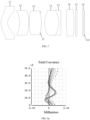
FIG. 1 illustrates a schematic cross-sectional view of the in-vehicle camera lens according to a first embodiment of the present disclosure. -
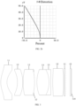
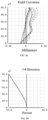
FIG. 2a illustrates a field curvature diagram of the in-vehicle camera lens according to the first embodiment of the present disclosure. -
FIG. 2b illustrates a distortion diagram of the in-vehicle camera lens according to the first embodiment of the present disclosure. -
FIG. 3 illustrates a schematic cross-sectional view of the in-vehicle camera lens according to a second embodiment of the present disclosure. -
FIG. 4a illustrates a field curvature diagram of the in-vehicle camera lens according to the second embodiment of the present disclosure. -
FIG. 4b illustrates a distortion diagram of the in-vehicle camera lens according to the second embodiment of the present disclosure. -
FIG. 5 illustrates a schematic cross-sectional view of the in-vehicle camera lens according to a third embodiment of the present disclosure. -
FIG. 6a illustrates a field curvature diagram of the in-vehicle camera lens according to the third embodiment of the present disclosure. -
FIG. 6b illustrates a distortion diagram of the in-vehicle camera lens according to the third embodiment of the present disclosure. -
FIG. 7 illustrates a schematic cross-sectional view of the in-vehicle camera lens according to a fourth embodiment of the present disclosure. -
FIG. 8a illustrates a field curvature diagram of the in-vehicle camera lens according to the fourth embodiment of the present disclosure. -
FIG. 8b illustrates a distortion diagram of the in-vehicle camera lens according to the fourth embodiment of the present disclosure. - In order to facilitate the understanding of the present disclosure, the present disclosure will be described more fully hereinafter with reference to the accompanying drawings. Several embodiments of the disclosure are presented in the drawings. However, the disclosure may be embodied in many different forms and is not limited to the embodiments described herein. Rather, these embodiments are provided so that this disclosure will be thorough and comprehensive.
- Unless defined otherwise, all technical and scientific terms used herein have the same meaning as commonly understood by one of ordinary skill in the art to which this disclosure belongs. The terminology items used herein in the description of the present disclosure are only for the purpose of describing specific embodiments, and are not intended to limit the present disclosure. The term "and / or" as used herein includes any and all combinations of one or more of the associated listed items.
- As illustrated in
FIG. 1 , the present disclosure provides an in-vehicle camera lens, from an object side to an image side thereof, the in-vehicle camera lens sequentially includes: - a first lens L1 with a negative refractive power, whose object side surface S1 is convex and image side surface S2 is concave;
- a second lens L2 with a negative refractive power, whose object side surface S3 is concave and image side surface S4 is convex;
- a third lens L3 with a positive refractive power, whose object side surface S5 and image side surface S6 are both convex;
- a stop S7;
- a fourth lens L4 with a positive refractive power, whose object side surface S8 and image side surface S9 are both convex;
- a fifth lens L5 with a negative refractive power, whose object side surface S10 is concave and image side surface S11 is concave or convex, which is not limited herein;
- the fifth lens L5 and the fourth lens L4 constituting a bonding lens group;
- a sixth lens L6 with a positive refractive power, whose object side surface S12 is convex and image side surface S13 is concave or convex, which is not limited herein; and
- a filter G1, whose object side surface is labeled as S14 and image side surface is labeled as S15;
- wherein, the second lens L2, the third lens L3, the fourth lens L4, and the fifth lens L5 are glass spherical lenses; the first lens L1 and the sixth lens L6 are both aspherical lenses; G2 is a cover glass, whose object side surface is labeled as S16 and image side surface is labeled as S17.
- The in-vehicle camera lens described above applies a combination of glass spherical surface and aspherical surface to provide a particular distortion for the in-vehicle camera lens. Compared with the existing vehicle-mounted in-vehicle camera lens, it significantly increases the distortion in a small FOV. It is more conducive to meet the special algorithm requirements of an in-vehicle system. The in-vehicle camera lens has a large aperture, improves the resolution of the in-vehicle camera lens while effectively controlling the diameter and the length of the in-vehicle camera lens, and achieves a small diameter and a large target surface. Meanwhile, by probably matching the glass materials of the lens, the problems of focus shift and sharply reduced resolution in a large temperature difference environment are overcome, thereby ensuring an excellent imaging quality in a large temperature difference environment and meeting the actual needs.
- The in-vehicle camera lens provided by the present disclosure satisfies the following expression:

- Furthermore, the in-vehicle camera lens satisfies the following expressions:


- Furthermore, the in-vehicle camera lens satisfies the following expression:

- Furthermore, the in-vehicle camera lens satisfies the following expressions:


- Furthermore, the in-vehicle camera lens satisfies the following expressions:


- Furthermore, the in-vehicle camera lens satisfies the following expression:

- Furthermore, the in-vehicle camera lens satisfies the following expressions:


- Furthermore, the in-vehicle camera lens satisfies the following expressions:

- Furthermore, the shapes of the respective aspherical surfaces of the first lens L1 and the sixth lens L6 satisfy the following expression:

- The in-vehicle camera lens that satisfies the above configuration not only maintains a small lens outer diameter and length, but also provide a particular distortion by being equipped with the first lens L1 with a glass aspheric surface. Because the sixth lens L6 include a glass aspheric surface, an astigmatism of the in-vehicle camera lens is effectively reduced, and the resolution capability of the in-vehicle camera lens is greatly improved. Furthermore, the in-vehicle camera lens provided by the present disclosure may optimize the lens ghost by controlling the shape of the lenses and improve the quality of image. The in-vehicle camera lens equipped with all glass-made lenses, may ensure the long-term stability of the lens in outdoor high and low temperature environments.
- The following further describes the present disclosure in multiple embodiments. In each of the following embodiments, the thickness and curvature radius of each lens in the in-vehicle camera lens are different. For specific differences, see the parameter tables in the embodiments. The following examples are merely preferred embodiments of the present disclosure, but the embodiments of the present disclosure are not limited only by the following examples.
- A schematic cross-sectional view of the in-vehicle camera lens according to the first embodiment is illustrated in
FIG.1 .A field curvature diagram of the in-vehicle camera lens according to the first embodiment is illustrated inFIG. 2a andFIG. 2b . Related parameters of each lens in the in-vehicle camera lens according to the first embodiment are shown in Table 1-1.Table 1-1 Surface No. Surface type Curvature radius Thickness Refractive index Abbe number Subj ect - Plane Infinity Infinity - - First lens S1 Aspheric surface 4.478743 2.256017 1.81 40.9 S2 Aspheric surface 2.266115 3.353162 - - Second lens S3 Spherical surface -6.21751 2.117002 1.64 55.5 S4 Spherical surface -8.12463 0.065315 - - Third lens S5 Spherical surface 11.29939 3.163642 1.69 54.9 S6 Spherical surface -11.2994 -0.10244 - - Stop S7 Spherical surface Infinity 1.866839 - - Fourth lens S8 Spherical surface 9.622295 3.562642 1.59 68.5 S9 Spherical surface -4.91578 0.005 1.52 50 Fifth lens S10 Spherical surface -4.91578 0.80962 1.85 23.8 S11 Spherical surface -18.8419 1.183007 - - Sixth lens S12 Aspheric surface 14.77657 2.417207 1.52 70.1 S13 Aspheric surface 35.31914 0.15 - - Filter S14 Plane Infinity 0.4 1.52 64.2 S15 Plane Infinity 2.126475 - - Cover glass S16 Plane Infinity 0.5 1.52 64.2 S17 Plane Infinity 0.134252 - - Image surface S18 Plane Infinity - - - The parameters of the aspheric surfaces of the first lens L1 and the sixth lens L6 of this embodiment are shown in Table 1-2.
Table 1-2 Surface No. K B C D E F S1 -0.948 -9.013e-04 -1.823e-04 7.070e-06 -8.622 e-08 0 S2 -0.656 -4.836e-03 -8.743e-04 7.796e-05 -3.305 e-06 0 S12 -1.535 -1.715e-03 1.266e-04 -9.217e-06 3.049e-07 -2.629e-09 S13 14.999 -4.127e-03 3.122e-04 -1.883e-05 6.138e-07 -7.701e-09 - A schematic cross-sectional view of the in-vehicle camera lens according to the second embodiment is illustrated in
FIG. 3 . A field curvature diagram of the in-vehicle camera lens according to the second embodiment is illustrated inFIG. 4a and FIG. 4b . Related design parameters of each lens in the in-vehicle camera lens according to the second embodiment are shown in Table 2-1.Table 2-1 Surface No. Surface type Curvature radius Thickness Refractive index Abbe number Subject - Plane Infinity Infinity - - First lens S1 Aspheric surface 4.838256 2.087534 1.81 40.9 S2 Aspheric surface 2.571794 3.557661 - - Second lens S3 Spherical surface -5.38627 1.813837 1.90 31.3 S4 Spherical surface -7.26476 0.097007 - - Third lens S5 Spherical surface 11.43274 3.890719 1.69 54.9 S6 Spherical surface -11.4327 -0.2738 - - Stop S7 Spherical surface Infinity 1.074281 - - Fourth lens S8 Spherical surface 7.417865 4.130265 1.59 68.5 S9 Spherical surface -5.70268 0.005 1.52 50 Fifth lens S10 Spherical surface -5.70268 0.598489 1.85 23.8 S11 Spherical surface -7924.8 0.626654 - - Sixth lens S12 Aspheric surface 16.07422 3.665452 1.52 70.1 S13 Aspheric surface 59.68892 0.15 - - Filter S14 Plane Infinity 0.4 1.52 64.2 S15 Plane Infinity 1.659725 - - Cover glass S16 Plane Infinity 0.4 1.52 64.2 S17 Plane Infinity 0.125447 - - Image surface S18 Plane Infinity - - - The parameters of the aspheric surfaces of the first lens L1 and the sixth lens L6 of this embodiment are shown in Table 2-2.
Table 2-2 Surface No. K B C D E F S1 -0.768 -1.487e-03 -1.800e-04 8.693e-06 -1.244 e-07 0 S2 -0.572 -5.219e-03 -6.481e-04 5.900e-05 -2.117 e-06 0 S12 5.527 -1.979e-03 8.525e-05 -9.309e-06 4.719 e-07 0 S13 -7.216 -4.821e-03 3.742e-04 -2.597e-05 1.194 e-06 0 - A schematic cross-sectional view of the in-vehicle camera lens according to the third embodiment is illustrated in
FIG. 5 . A field curvature diagram of the in-vehicle camera lens according to the third embodiment is illustrated inFIG. 6a andFIG. 6b . Related design parameters of each lens in the in-vehicle camera lens according to the third embodiment are shown in Table 3-1.Table 3-1 Surface No. Surface type Curvature radius Thickness Refractive index Abbe number Subject - Plane Infinity Infinity - - First lens S1 Aspheric surface 4.384313 1.955523 1.81 40.9 S2 Aspheric surface 2.486175 3.438369 - - Second lens S3 Spherical surface -7.10429 2.634684 1.95 32.3 S4 Spherical surface -9.83808 0.099977 - - Third lens S5 Spherical surface 12.84571 3.53053 1.61 55.1 S6 Spherical surface -10.7629 -0.28793 - - Stop S7 Spherical surface Infinity 1.232792 - - Fourth lens S8 Spherical surface 7.402686 4.082569 1.59 68.5 S9 Spherical surface -6.5001 0.005 1.52 50 Fifth lens S10 Spherical surface -6.5001 0.6 1.81 22.7 S11 Spherical surface -199.298 1.57034 - - Sixth lens S12 Aspheric surface 14.56867 2.143664 1.60 65.3 S13 Aspheric surface 29.44758 0.5 - - Filter S14 Plane Infinity 0.4 1.52 64.2 S15 Plane Infinity 1.586954 - - Cover glass S16 Plane Infinity 0.4 1.52 64.2 S17 Plane Infinity 0.112532 - - Image surface S18 Plane Infinity - - - The parameters of the aspheric surfaces of the first lens L1 and the sixth lens L6 of this embodiment are shown in Table 3-2.
Table 3-2 Surface No. K B C D E F S1 -0.818 -1.059e-03 -2.398e-04 1.060e-05 -1.486 e-07 0 S2 -0.619 -4.151e-03 -9.312e-04 8.436e-05 -3.107 e-06 0 S12 -5.981 -2.565e-03 1.755e-04 -1.649e-05 5.955 e-07 0 S13 -13.599 -5.374e-03 4.092e-04 -2.369e-05 6.725 e-07 0 - A schematic cross-sectional view of the in-vehicle camera lens according to the fourth embodiment is illustrated in
FIG. 7 . A field curvature diagram of the in-vehicle camera lens according to the fourth embodiment is illustrated inFIG. 8a and FIG. 8b . Related design parameters of each lens in the in-vehicle camera lens according to the fourth embodiment are shown in Table 4-1.Table 4-1 Surface No. Surface type Curvature radius Thickness Refractive index Abbe number Subject - Plane Infinity Infinity - - First lens S1 Aspheric surface 4.364936 2.158898 1.81 40.9 S2 Aspheric surface 2.404071 3.27911 - - Second lens S3 Spherical surface -6.17539 2.149924 1.95 32.3 S4 Spherical surface -8.87064 0.099848 - - Third lens S5 Spherical surface 11.30523 4.220957 1.61 55.1 S6 Spherical surface -11.3052 -0.23525 - - Stop S7 Spherical surface Infinity 0.507302 - - Fourth lens S8 Spherical surface 7.848862 4.268829 1.59 68.5 S9 Spherical surface -4.6335 0.005 1.52 50 Fifth lens S10 Spherical surface -4.6335 0.549899 1.81 22.7 S11 Spherical surface 49.6618 0.523369 - - Sixth lens S12 Aspheric surface 16.08075 3.327354 1.60 65.3 S13 Aspheric surface -30.5119 0.15 - - Filter S14 Plane Infinity 0.5 1.52 64.2 S15 Plane Infinity 1.877865 - - Cover glass S16 Plane Infinity 0.5 1.52 64.2 S17 Plane Infinity 0.121894 - - Image surface S18 Plane Infinity - - - The parameters of the aspheric surfaces of the first lens L1 and the sixth lens L6 of this embodiment are shown in Table 4-2.
Table 4-2 Surface No. K B C D E F S1 -3.727 3.222e-03 -3.813e-04 1.309e-05 -1.591 e-07 0 S2 -0.626 -4.079e-03 -9.308e-04 7.204e-05 -2.458 e-06 0 S12 5.135 -1.788e-03 3.544e-05 3.075e-06 -8.204e-07 4.001e-08 S13 2.273 -3.514e-03 2.113e-04 -7.597e-06 4.131e-08 5.228e-09 - In summary, according to the description in the foregoing first, second third, and fourth embodiments, the related optical parameter of the in-vehicle camera lens provided by present disclosure is shown in Table 5.
- As illustrated in table 5, table 5 shows optical characteristics corresponding of each of the first, second third, and fourth embodiments. Table 5 includes the system focal length f, the system optical total length TTL, the aperture number F#, and the field angle 2θ of the in-vehicle camera lens.
Table 5 Expression Embodiment 1 Embodiment 2 Embodiment 3 Embodiment 4 f (mm) 6.305 6.293 6.3 6.38 TTL(mm) 24 24 24 24 F# 1.63 1.62 1.61 1.615 2θ 100° 100° 100° 100° D1/(YIH*f) 0.199 0.247 0.196865 0.1964 TTL/f 3.81 3.81 3.809533 3.761066 R1/f 0.71 0.7688 0.695924 0.684 f1/f -1.65 -1.831431 -2.087202 -2.04 (Y12-Yref12)/ Yref12 -5.1% -5.25% -5.5% -5.9% R21/f -0.986 -0.855887 -1.127667 -0.9677 R41/f 1.526 1.178712 1.175 1.2385 f/R52 -0.33 -0.0008 -0.03 0.128 R61/f 2.34 2.554 2.312493 2.52 f/f6 0.135 0.1535 0.137962 0.308 f3/f 1.37 1.4069 1.598485 1.3821 (dn/dt)4 (unit: 10-6/°C) -7.4 -7.4 -7.4 -7.4 f4/f 0.95 0.975783 1.037106 0.8797
Claims (14)
- An in-vehicle camera lens, the in-vehicle camera lens sequentially consisting essentially of, from an object side to an image side thereof:a first lens (L1) with a negative refractive power, whose object side surface (S1) is convex and image side surface (S2) is concave;a second lens (L2) with a negative refractive power, whose object side surface (S3) is concave and image side surface (S4) is convex;a third lens (L3) with a positive refractive power, whose object side surface (S5) and image side surface (S6) are both convex;a stop (S7);a fourth lens (L4) with a positive refractive power, whose object side surface (S8) and image side surface (S9) are both convex;a fifth lens (L5) with a negative refractive power, whose object side surface (S10) is concave surface; wherein the fifth lens and the fourth lens constitute a bonding lens group;a sixth lens (L6) with a positive refractive power, whose object side surface (S12) is convex; anda filter (G1);wherein the second lens (L2), the third lens (L3), the fourth lens (L4), and the fifth lens (L5) are glass spherical lenses; and the first lens (L1) and the sixth lens (L6) are both glass aspherical lenses;wherein the in-vehicle camera lens satisfies the following expressions:


 where R21 represents a curvature radius of the object side surface (S3) of the second lens (L2);R41 represents a curvature radius of the object side surface (S8) of the fourth lens (L4);R52 represents a curvature radius of the image side surface (S11) of the fifth lens (L5); andf represents a focal length of the in-vehicle camera lens;wherein the in-vehicle camera lens satisfies the following expressions:
 where (dn/dt)4 represents a temperature coefficient of refractive index of the fourth lens (L4);and f4 represents a focal length of the fourth lens (L4).
 - The in-vehicle camera lens as claimed in claim 1, wherein the in-vehicle camera lens satisfies the following expression:
 where D1 represents a maximum effective diameter of the first lens (L1);YIH represents a maximum image circle radius of the in-vehicle camera lens; andf represents a focal length of the in-vehicle camera lens.
 - The in-vehicle camera lens as claimed in any one of claim 1 and 2, wherein the in-vehicle camera lens satisfies the following expressions:


 where R1 represents a curvature radius of a center of the object side surface (S 1) of the first lens (L1);f1 represents a focal length of the first lens (L1);f represents a focal length of the in-vehicle camera lens;Y12 represents a real image height of the in-vehicle camera lens at 12° FOV; andYref12 represents an ideal paraxial image height of the in-vehicle camera lens at 12° FOV
 - The in-vehicle camera lens as claimed in any one of claim 1 to 3, wherein the in-vehicle camera lens satisfies the following expression:
 where TTL represents an optical total length of the in-vehicle camera lens; andf represents a focal length of the in-vehicle camera lens.
 - The in-vehicle camera lens as claimed in any one of claim 1 to 4, wherein the in-vehicle camera lens satisfies the following expressions:

 where R61 represents a curvature radius of a center of the object side surface (S 12) of the sixth lens (L6);f represents a focal length of the in-vehicle camera lens; andf6 represents a focal length of the sixth lens (L6).
 - The in-vehicle camera lens as claimed in any one of claim 1 to 5, wherein the in-vehicle camera lens satisfies the following expression:
 where f3 represents a focal length of the third lens (L3); andf represents a focal length of the in-vehicle camera lens.
 - The in-vehicle camera lens as claimed in any one of claim 1 to 6, wherein the in-vehicle camera lens satisfies the following expressions:
 where Vd4 represents an abbe number of the fourth lens (L4);Vd5 represents an abbe number of the fifth lens (L5);Vd6 represents an abbe number of the sixth lens (L6); andNd1 represents a refractive index of the first lens (L1).
 - The in-vehicle camera lens as claimed in any one of claim 1 to 7, wherein the shapes of the respective aspherical surfaces of the first lens (L1) and the sixth lens (L6) satisfy the following expression:
 where z represents a vector height between a point on the surface and a vertex of the surface along an optical axis of the in-vehicle camera lens;h represents a distance between the point on the surface and the optical axis;c represents a curvature of the vertex of the surface;K represents a quadratic surface coefficient;B represents a fourth order surface coefficient;C represents a sixth order surface coefficient;D represents an eighth order surface coefficient;E represents a tenth order surface coefficient; andF represents a twelfth order surface coefficient.
 - The in-vehicle camera lens as claimed in any one of claim 1 to 8, comprising a cover glass disposed at an image side of the filter.
- The in-vehicle camera lens as claimed in any one of claim 1 to 9, wherein the object side surface (S1) of the first lens (L1) is a aspheric surface; the image side surface (S2) of the first lens (L1) is an aspheric surface.
- The in-vehicle camera lens as claimed in any one of claim 1 to 10, wherein the object side surface (S3) and the image side surface (S4) of the second lens (L2) are spherical.
- The in-vehicle camera lens as claimed in any one of claim 1 to 11, wherein an image side surface (S11) of the fifth lens (L5) is spherical.
- The in-vehicle camera lens as claimed in any one of claim 1 to 12, wherein an image side surface (S13) of the sixth lens (L6) is aspheric surface.
- The in-vehicle camera lens as claimed in any one of claim 1 to 13, wherein a total number of lenses (L1, L2, L3, L4, L5, L6) of the in-vehicle camera lens is six.
Applications Claiming Priority (2)
| Application Number | Priority Date | Filing Date | Title |
|---|---|---|---|
| CN201810629640.7A CN108681050B (en) | 2018-06-19 | 2018-06-19 | car camera lens |
| PCT/CN2019/085195 WO2019242411A1 (en) | 2018-06-19 | 2019-04-30 | Onboard camera lens |
Publications (4)
| Publication Number | Publication Date |
|---|---|
| EP3798708A1 EP3798708A1 (en) | 2021-03-31 |
| EP3798708A4 EP3798708A4 (en) | 2021-08-11 |
| EP3798708C0 EP3798708C0 (en) | 2024-06-12 |
| EP3798708B1 true EP3798708B1 (en) | 2024-06-12 |
Family
ID=63811352
Family Applications (1)
| Application Number | Title | Priority Date | Filing Date |
|---|---|---|---|
| EP19822125.1A Active EP3798708B1 (en) | 2018-06-19 | 2019-04-30 | Onboard camera lens |
Country Status (7)
| Country | Link |
|---|---|
| US (1) | US11353687B2 (en) |
| EP (1) | EP3798708B1 (en) |
| JP (1) | JP7016966B2 (en) |
| KR (1) | KR102516446B1 (en) |
| CN (1) | CN108681050B (en) |
| PL (1) | PL3798708T3 (en) |
| WO (1) | WO2019242411A1 (en) |
Families Citing this family (27)
| Publication number | Priority date | Publication date | Assignee | Title |
|---|---|---|---|---|
| CN108681050B (en) | 2018-06-19 | 2019-12-03 | 江西联创电子有限公司 | car camera lens |
| CN109541780B (en) * | 2018-11-16 | 2020-09-22 | 江西联创电子有限公司 | Optical lens and imaging apparatus |
| CN109445068B (en) * | 2018-12-05 | 2020-02-18 | 江西联创电子有限公司 | Vehicle camera lens and imaging equipment |
| CN109407279B (en) * | 2018-12-12 | 2021-09-14 | 江西联创电子有限公司 | Wide-angle lens and imaging apparatus |
| CN109445077B (en) * | 2019-01-10 | 2021-10-29 | 宁波舜宇车载光学技术有限公司 | Optical lens and imaging apparatus |
| CN109975954B (en) * | 2019-04-04 | 2024-08-27 | 广东弘景光电科技股份有限公司 | High-pixel road monitoring optical system and camera module applying same |
| CN110646919B (en) * | 2019-08-22 | 2021-06-25 | 江西联创电子有限公司 | Fisheye lens |
| CN110596871B (en) * | 2019-10-16 | 2024-02-27 | 杭州图谱光电科技有限公司 | High-resolution large-aperture motion DV lens |
| CN113448057A (en) * | 2020-03-25 | 2021-09-28 | 宁波舜宇车载光学技术有限公司 | Optical lens and electronic device |
| CN111367047B (en) * | 2020-03-31 | 2024-06-18 | 玉晶光电(厦门)有限公司 | Optical imaging lens |
| WO2022060011A1 (en) | 2020-09-17 | 2022-03-24 | 주식회사 엘지에너지솔루션 | Separator manufacturing apparatus and separator manufacturing method |
| CN112255766B (en) * | 2020-11-06 | 2022-07-19 | 天津欧菲光电有限公司 | Optical imaging system and electronic device |
| CN113009674B (en) * | 2021-03-12 | 2024-02-23 | 宁波舜宇车载光学技术有限公司 | Optical lens and electronic device |
| WO2022100731A1 (en) * | 2020-11-13 | 2022-05-19 | 宁波舜宇车载光学技术有限公司 | Optical lens and electronic device |
| JP7796306B2 (en) * | 2021-05-26 | 2026-01-09 | パナソニックIpマネジメント株式会社 | Imaging optical system and camera |
| CN113376804B (en) * | 2021-06-16 | 2024-04-05 | 玉晶光电(厦门)有限公司 | Optical imaging lens |
| CN116413870B (en) * | 2021-12-30 | 2026-01-02 | 深圳市速腾聚创科技有限公司 | Receiving lens, receiving module, ranging device and electronic equipment |
| CN114384670B (en) * | 2022-02-24 | 2026-04-28 | 协益电子(苏州)有限公司 | A vehicle-mounted forward-looking optical lens |
| CN115268018B (en) * | 2022-07-12 | 2025-03-18 | 江西晶超光学有限公司 | Optical systems, camera modules and electronic equipment |
| CN115407487B (en) * | 2022-08-25 | 2024-09-20 | 嘉兴中润光学科技股份有限公司 | Vehicle-mounted lens and imaging device |
| CN115542517B (en) * | 2022-09-20 | 2026-03-10 | 舜宇光学(中山)有限公司 | Glass-plastic mixed optical system |
| CN116794814A (en) * | 2023-05-12 | 2023-09-22 | 河南翊轩光电科技有限公司 | Lens and imaging device |
| CN117111277A (en) | 2023-08-03 | 2023-11-24 | 辰瑞光学(苏州)有限公司 | Camera optical lens |
| CN116841010B (en) * | 2023-09-01 | 2024-01-05 | 江西联益光学有限公司 | Optical lens |
| CN118465974B (en) * | 2024-06-04 | 2025-10-28 | 厦门力鼎光电股份有限公司 | An optical imaging lens |
| CN119322409B (en) * | 2024-12-19 | 2025-04-15 | 江西联创电子有限公司 | Optical lens |
| CN121254466B (en) * | 2025-12-03 | 2026-04-28 | 宁波舜宇车载光学技术有限公司 | Optical lens and electronic device |
Family Cites Families (25)
| Publication number | Priority date | Publication date | Assignee | Title |
|---|---|---|---|---|
| JPH06347695A (en) * | 1993-06-14 | 1994-12-22 | Nikon Corp | Projection lens |
| KR100252639B1 (en) * | 1997-03-28 | 2000-05-01 | 유무성 | Finder optical system |
| US7633688B2 (en) * | 2005-06-01 | 2009-12-15 | Olympus Imaging Corp. | Image forming optical system |
| JP4864403B2 (en) * | 2005-09-29 | 2012-02-01 | 富士フイルム株式会社 | Wide-angle lens system and imaging device |
| JP5058475B2 (en) | 2005-10-11 | 2012-10-24 | 電気化学工業株式会社 | Alumina and production method thereof |
| JP4855042B2 (en) * | 2005-10-17 | 2012-01-18 | 株式会社リコー | Photography optical system, photography lens unit and camera |
| US8780463B2 (en) | 2010-06-24 | 2014-07-15 | Ricoh Company, Ltd. | Image-forming lens, and imaging apparatus and information device using the image-forming lens |
| KR101136939B1 (en) * | 2010-07-15 | 2012-04-20 | 엘지이노텍 주식회사 | Super wide angle optic lens system |
| KR101422910B1 (en) * | 2012-04-30 | 2014-07-23 | 삼성전기주식회사 | Optical system for camera |
| CN103576290B (en) * | 2013-10-30 | 2016-01-06 | 宁波舜宇车载光学技术有限公司 | A kind of wide-angle lens |
| CN103676092B (en) * | 2013-10-30 | 2015-09-30 | 宁波舜宇车载光学技术有限公司 | A kind of high-pixel optical lens |
| CN204188869U (en) * | 2014-09-22 | 2015-03-04 | 青岛歌尔声学科技有限公司 | A kind of large aperture bugeye lens |
| CN105044885B (en) * | 2015-06-23 | 2018-03-16 | 信华精机有限公司 | A kind of optical imaging system for vehicle-mounted monitoring |
| KR102508341B1 (en) * | 2015-09-04 | 2023-03-10 | 삼성전자주식회사 | Super wide angle optical system |
| KR102600453B1 (en) | 2016-02-19 | 2023-11-10 | 삼성전자주식회사 | Optical lens assembly and electronic apparatus having the same |
| CN105892024B (en) * | 2016-03-11 | 2018-11-23 | 信华精机有限公司 | A kind of high definition fish eye optical camera lens |
| JP2017228832A (en) * | 2016-06-20 | 2017-12-28 | パナソニックIpマネジメント株式会社 | Imaging device |
| US10254511B2 (en) * | 2016-06-24 | 2019-04-09 | Young Optics Inc. | Optical lens |
| CN106125258B (en) * | 2016-09-07 | 2018-07-13 | 江西联益光学有限公司 | Wide-angle lens |
| CN113189742B (en) | 2016-11-15 | 2023-05-16 | 宁波舜宇车载光学技术有限公司 | Optical lens |
| TWI655473B (en) | 2017-05-08 | 2019-04-01 | 大立光電股份有限公司 | Imaging system lens group, image capturing device and electronic device |
| CN107037570B (en) * | 2017-05-26 | 2023-06-16 | 东莞市宇瞳光学科技股份有限公司 | Athermalization high-definition prime lens |
| KR102550509B1 (en) * | 2017-11-21 | 2023-07-03 | 삼성전기주식회사 | Optical system |
| US20190155006A1 (en) * | 2017-11-22 | 2019-05-23 | Sunny Optical Overseas Limited | Optical wide angle lens |
| CN108681050B (en) * | 2018-06-19 | 2019-12-03 | 江西联创电子有限公司 | car camera lens |
-
2018
- 2018-06-19 CN CN201810629640.7A patent/CN108681050B/en active Active
-
2019
- 2019-04-30 JP JP2020551432A patent/JP7016966B2/en active Active
- 2019-04-30 KR KR1020207026568A patent/KR102516446B1/en active Active
- 2019-04-30 WO PCT/CN2019/085195 patent/WO2019242411A1/en not_active Ceased
- 2019-04-30 PL PL19822125.1T patent/PL3798708T3/en unknown
- 2019-04-30 EP EP19822125.1A patent/EP3798708B1/en active Active
-
2020
- 2020-01-15 US US16/744,145 patent/US11353687B2/en active Active
Non-Patent Citations (2)
| Title |
|---|
| "Handbook of optical systems, Aberration theory and correction of optical systems, Chapter 31: Correction of Aberrations ED - Gross H", 1 January 2007, HANDBOOK OF OPTICAL SYSTEMS, ABERRATION THEORY AND CORRECTION OF OPTICAL SYSTEMS, WILEY-VCH, WEINHEIM, DE, PAGE(S) 215 - 221, 225, ISBN: 978-3-527-40379-0, XP002719371 * |
| "Modern Optical Engineering, The Design of Optical Systems", 1 January 1990, MCGRAW-HILL, INC., ISBN: 978-0-07-059174-5, article WARREN J. SMITH: "Modern Optical Engineering, The Design of Optical Systems", pages: 70 - 71, XP055152063 * |
Also Published As
| Publication number | Publication date |
|---|---|
| EP3798708C0 (en) | 2024-06-12 |
| US11353687B2 (en) | 2022-06-07 |
| WO2019242411A1 (en) | 2019-12-26 |
| EP3798708A4 (en) | 2021-08-11 |
| JP2021516793A (en) | 2021-07-08 |
| PL3798708T3 (en) | 2024-09-30 |
| KR102516446B1 (en) | 2023-03-30 |
| EP3798708A1 (en) | 2021-03-31 |
| KR20200119871A (en) | 2020-10-20 |
| JP7016966B2 (en) | 2022-02-07 |
| CN108681050A (en) | 2018-10-19 |
| US20200150399A1 (en) | 2020-05-14 |
| CN108681050B (en) | 2019-12-03 |
Similar Documents
| Publication | Publication Date | Title |
|---|---|---|
| EP3798708B1 (en) | Onboard camera lens | |
| EP3865926B1 (en) | Vehicle-mounted camera lens and imaging device | |
| US7697220B2 (en) | Image forming optical system | |
| EP3940442B1 (en) | Optical imaging lens and imaging device | |
| CN110727087B (en) | Wide-angle lens | |
| EP4682607A1 (en) | Optical lens | |
| WO2019228127A1 (en) | Wide-angle lens | |
| CN112014960A (en) | High-resolution large-visual-angle vehicle-mounted fisheye optical lens and vehicle-mounted all-around-view lens | |
| CN110646920A (en) | Long-focus vehicle-mounted optical lens and working method thereof | |
| CN112014962B (en) | A high-resolution and wide-angle vehicle optical lens and a vehicle rearview mirror | |
| CN112285883B (en) | Ultra-wide angle optical system and imaging method thereof | |
| CN113985587B (en) | Optical imaging lens and imaging apparatus | |
| CN113960761A (en) | Optical lens, camera module, electronic equipment and automobile | |
| CN112882206A (en) | Optical system, camera module, electronic equipment and automobile | |
| CN115718361B (en) | Optical systems, cameras and vehicles | |
| CN113253426B (en) | Optical system, lens module and electronic equipment | |
| CN113156621B (en) | Optical imaging lens and imaging apparatus | |
| CN112099195B (en) | Optical imaging systems, imaging modules, electronic devices and automobiles | |
| CN205679845U (en) | A vehicle-mounted high-definition fisheye lens | |
| CN211627917U (en) | Camera module, electronic device and automobile | |
| CN212410950U (en) | Vehicle-mounted optical lens with high resolution and large visual angle and automobile rearview mirror | |
| CN210742598U (en) | Long-focus vehicle-mounted optical lens | |
| US20250208385A1 (en) | Optical system, vehicle-mounted camera and vehicle | |
| CN112099190A (en) | Optical lens, camera module and electronic equipment | |
| CN219349244U (en) | In-car fatigue driving monitoring lens |
Legal Events
| Date | Code | Title | Description |
|---|---|---|---|
| STAA | Information on the status of an ep patent application or granted ep patent |
Free format text: STATUS: THE INTERNATIONAL PUBLICATION HAS BEEN MADE |
|
| PUAI | Public reference made under article 153(3) epc to a published international application that has entered the european phase |
Free format text: ORIGINAL CODE: 0009012 |
|
| STAA | Information on the status of an ep patent application or granted ep patent |
Free format text: STATUS: REQUEST FOR EXAMINATION WAS MADE |
|
| 17P | Request for examination filed |
Effective date: 20201209 |
|
| AK | Designated contracting states |
Kind code of ref document: A1 Designated state(s): AL AT BE BG CH CY CZ DE DK EE ES FI FR GB GR HR HU IE IS IT LI LT LU LV MC MK MT NL NO PL PT RO RS SE SI SK SM TR |
|
| AX | Request for extension of the european patent |
Extension state: BA ME |
|
| TPAC | Observations filed by third parties |
Free format text: ORIGINAL CODE: EPIDOSNTIPA |
|
| A4 | Supplementary search report drawn up and despatched |
Effective date: 20210712 |
|
| RIC1 | Information provided on ipc code assigned before grant |
Ipc: G02B 7/02 20210101ALN20210706BHEP Ipc: G02B 13/04 20060101ALI20210706BHEP Ipc: G02B 9/60 20060101ALI20210706BHEP Ipc: G02B 13/00 20060101AFI20210706BHEP |
|
| DAV | Request for validation of the european patent (deleted) | ||
| DAX | Request for extension of the european patent (deleted) | ||
| STAA | Information on the status of an ep patent application or granted ep patent |
Free format text: STATUS: EXAMINATION IS IN PROGRESS |
|
| 17Q | First examination report despatched |
Effective date: 20220708 |
|
| GRAP | Despatch of communication of intention to grant a patent |
Free format text: ORIGINAL CODE: EPIDOSNIGR1 |
|
| STAA | Information on the status of an ep patent application or granted ep patent |
Free format text: STATUS: GRANT OF PATENT IS INTENDED |
|
| RIC1 | Information provided on ipc code assigned before grant |
Ipc: G02B 7/02 20210101ALN20240126BHEP Ipc: G02B 13/04 20060101ALI20240126BHEP Ipc: G02B 9/60 20060101ALI20240126BHEP Ipc: G02B 13/00 20060101AFI20240126BHEP |
|
| INTG | Intention to grant announced |
Effective date: 20240216 |
|
| GRAS | Grant fee paid |
Free format text: ORIGINAL CODE: EPIDOSNIGR3 |
|
| GRAA | (expected) grant |
Free format text: ORIGINAL CODE: 0009210 |
|
| STAA | Information on the status of an ep patent application or granted ep patent |
Free format text: STATUS: THE PATENT HAS BEEN GRANTED |
|
| AK | Designated contracting states |
Kind code of ref document: B1 Designated state(s): AL AT BE BG CH CY CZ DE DK EE ES FI FR GB GR HR HU IE IS IT LI LT LU LV MC MK MT NL NO PL PT RO RS SE SI SK SM TR |
|
| REG | Reference to a national code |
Ref country code: GB Ref legal event code: FG4D |
|
| REG | Reference to a national code |
Ref country code: CH Ref legal event code: EP |
|
| REG | Reference to a national code |
Ref country code: DE Ref legal event code: R096 Ref document number: 602019053657 Country of ref document: DE |
|
| REG | Reference to a national code |
Ref country code: IE Ref legal event code: FG4D |
|
| U01 | Request for unitary effect filed |
Effective date: 20240707 |
|
| U07 | Unitary effect registered |
Designated state(s): AT BE BG DE DK EE FI FR IT LT LU LV MT NL PT SE SI Effective date: 20240716 |
|
| REG | Reference to a national code |
Ref country code: SK Ref legal event code: T3 Ref document number: E 44423 Country of ref document: SK |
|
| U1N | Appointed representative for the unitary patent procedure changed after the registration of the unitary effect |
Representative=s name: PLAVSA, OLGA; RS |
|
| PG25 | Lapsed in a contracting state [announced via postgrant information from national office to epo] |
Ref country code: HR Free format text: LAPSE BECAUSE OF FAILURE TO SUBMIT A TRANSLATION OF THE DESCRIPTION OR TO PAY THE FEE WITHIN THE PRESCRIBED TIME-LIMIT Effective date: 20240612 |
|
| PG25 | Lapsed in a contracting state [announced via postgrant information from national office to epo] |
Ref country code: GR Free format text: LAPSE BECAUSE OF FAILURE TO SUBMIT A TRANSLATION OF THE DESCRIPTION OR TO PAY THE FEE WITHIN THE PRESCRIBED TIME-LIMIT Effective date: 20240913 |
|
| PG25 | Lapsed in a contracting state [announced via postgrant information from national office to epo] |
Ref country code: ES Free format text: LAPSE BECAUSE OF FAILURE TO SUBMIT A TRANSLATION OF THE DESCRIPTION OR TO PAY THE FEE WITHIN THE PRESCRIBED TIME-LIMIT Effective date: 20240612 |
|
| PG25 | Lapsed in a contracting state [announced via postgrant information from national office to epo] |
Ref country code: NO Free format text: LAPSE BECAUSE OF FAILURE TO SUBMIT A TRANSLATION OF THE DESCRIPTION OR TO PAY THE FEE WITHIN THE PRESCRIBED TIME-LIMIT Effective date: 20240912 Ref country code: HR Free format text: LAPSE BECAUSE OF FAILURE TO SUBMIT A TRANSLATION OF THE DESCRIPTION OR TO PAY THE FEE WITHIN THE PRESCRIBED TIME-LIMIT Effective date: 20240612 Ref country code: GR Free format text: LAPSE BECAUSE OF FAILURE TO SUBMIT A TRANSLATION OF THE DESCRIPTION OR TO PAY THE FEE WITHIN THE PRESCRIBED TIME-LIMIT Effective date: 20240913 Ref country code: ES Free format text: LAPSE BECAUSE OF FAILURE TO SUBMIT A TRANSLATION OF THE DESCRIPTION OR TO PAY THE FEE WITHIN THE PRESCRIBED TIME-LIMIT Effective date: 20240612 Ref country code: RS Free format text: LAPSE BECAUSE OF FAILURE TO SUBMIT A TRANSLATION OF THE DESCRIPTION OR TO PAY THE FEE WITHIN THE PRESCRIBED TIME-LIMIT Effective date: 20240912 |
|
| PG25 | Lapsed in a contracting state [announced via postgrant information from national office to epo] |
Ref country code: IS Free format text: LAPSE BECAUSE OF FAILURE TO SUBMIT A TRANSLATION OF THE DESCRIPTION OR TO PAY THE FEE WITHIN THE PRESCRIBED TIME-LIMIT Effective date: 20241012 |
|
| PG25 | Lapsed in a contracting state [announced via postgrant information from national office to epo] |
Ref country code: CZ Free format text: LAPSE BECAUSE OF FAILURE TO SUBMIT A TRANSLATION OF THE DESCRIPTION OR TO PAY THE FEE WITHIN THE PRESCRIBED TIME-LIMIT Effective date: 20240612 |
|
| PG25 | Lapsed in a contracting state [announced via postgrant information from national office to epo] |
Ref country code: RO Free format text: LAPSE BECAUSE OF FAILURE TO SUBMIT A TRANSLATION OF THE DESCRIPTION OR TO PAY THE FEE WITHIN THE PRESCRIBED TIME-LIMIT Effective date: 20240612 |
|
| PG25 | Lapsed in a contracting state [announced via postgrant information from national office to epo] |
Ref country code: SM Free format text: LAPSE BECAUSE OF FAILURE TO SUBMIT A TRANSLATION OF THE DESCRIPTION OR TO PAY THE FEE WITHIN THE PRESCRIBED TIME-LIMIT Effective date: 20240612 |
|
| PG25 | Lapsed in a contracting state [announced via postgrant information from national office to epo] |
Ref country code: SM Free format text: LAPSE BECAUSE OF FAILURE TO SUBMIT A TRANSLATION OF THE DESCRIPTION OR TO PAY THE FEE WITHIN THE PRESCRIBED TIME-LIMIT Effective date: 20240612 Ref country code: RO Free format text: LAPSE BECAUSE OF FAILURE TO SUBMIT A TRANSLATION OF THE DESCRIPTION OR TO PAY THE FEE WITHIN THE PRESCRIBED TIME-LIMIT Effective date: 20240612 Ref country code: IS Free format text: LAPSE BECAUSE OF FAILURE TO SUBMIT A TRANSLATION OF THE DESCRIPTION OR TO PAY THE FEE WITHIN THE PRESCRIBED TIME-LIMIT Effective date: 20241012 Ref country code: CZ Free format text: LAPSE BECAUSE OF FAILURE TO SUBMIT A TRANSLATION OF THE DESCRIPTION OR TO PAY THE FEE WITHIN THE PRESCRIBED TIME-LIMIT Effective date: 20240612 |
|
| PLBE | No opposition filed within time limit |
Free format text: ORIGINAL CODE: 0009261 |
|
| STAA | Information on the status of an ep patent application or granted ep patent |
Free format text: STATUS: NO OPPOSITION FILED WITHIN TIME LIMIT |
|
| 26N | No opposition filed |
Effective date: 20250313 |
|
| U20 | Renewal fee for the european patent with unitary effect paid |
Year of fee payment: 7 Effective date: 20250421 |
|
| PGFP | Annual fee paid to national office [announced via postgrant information from national office to epo] |
Ref country code: PL Payment date: 20250408 Year of fee payment: 7 |
|
| PGFP | Annual fee paid to national office [announced via postgrant information from national office to epo] |
Ref country code: SK Payment date: 20250424 Year of fee payment: 7 |
|
| REG | Reference to a national code |
Ref country code: CH Ref legal event code: H13 Free format text: ST27 STATUS EVENT CODE: U-0-0-H10-H13 (AS PROVIDED BY THE NATIONAL OFFICE) Effective date: 20251125 |
|
| PG25 | Lapsed in a contracting state [announced via postgrant information from national office to epo] |
Ref country code: MC Free format text: LAPSE BECAUSE OF FAILURE TO SUBMIT A TRANSLATION OF THE DESCRIPTION OR TO PAY THE FEE WITHIN THE PRESCRIBED TIME-LIMIT Effective date: 20240612 |
|
| GBPC | Gb: european patent ceased through non-payment of renewal fee |
Effective date: 20250430 |
|
| PG25 | Lapsed in a contracting state [announced via postgrant information from national office to epo] |
Ref country code: GB Free format text: LAPSE BECAUSE OF NON-PAYMENT OF DUE FEES Effective date: 20250430 |
|
| PG25 | Lapsed in a contracting state [announced via postgrant information from national office to epo] |
Ref country code: CH Free format text: LAPSE BECAUSE OF NON-PAYMENT OF DUE FEES Effective date: 20250430 |
|
| PG25 | Lapsed in a contracting state [announced via postgrant information from national office to epo] |
Ref country code: IE Free format text: LAPSE BECAUSE OF NON-PAYMENT OF DUE FEES Effective date: 20250430 |