EP3798556A1 - A cooling device - Google Patents
A cooling device Download PDFInfo
- Publication number
- EP3798556A1 EP3798556A1 EP20196828.6A EP20196828A EP3798556A1 EP 3798556 A1 EP3798556 A1 EP 3798556A1 EP 20196828 A EP20196828 A EP 20196828A EP 3798556 A1 EP3798556 A1 EP 3798556A1
- Authority
- EP
- European Patent Office
- Prior art keywords
- shelf
- cover
- drawer
- housing
- cooling device
- Prior art date
- Legal status (The legal status is an assumption and is not a legal conclusion. Google has not performed a legal analysis and makes no representation as to the accuracy of the status listed.)
- Granted
Links
Images




Classifications
-
- F—MECHANICAL ENGINEERING; LIGHTING; HEATING; WEAPONS; BLASTING
- F25—REFRIGERATION OR COOLING; COMBINED HEATING AND REFRIGERATION SYSTEMS; HEAT PUMP SYSTEMS; MANUFACTURE OR STORAGE OF ICE; LIQUEFACTION SOLIDIFICATION OF GASES
- F25D—REFRIGERATORS; COLD ROOMS; ICE-BOXES; COOLING OR FREEZING APPARATUS NOT OTHERWISE PROVIDED FOR
- F25D25/00—Charging, supporting, and discharging the articles to be cooled
- F25D25/02—Charging, supporting, and discharging the articles to be cooled by shelves
- F25D25/024—Slidable shelves
- F25D25/025—Drawers
Definitions
- the invention relates to a refrigerator having a drawer and a shelf provided at the upper vicinity of said drawer.
- Cooling devices are devices which keep foods without deterioration and which cool beverages and which essentially have a closed chamber and which function by means of motor.
- refrigerators there is particularly a section where vegetables and fruits are kept.
- this section is generally a drawer which can be easily opened and closed in order for the user to easily reach vegetables and fruits.
- said drawers are desired to be kept at different temperatures for keeping vegetables and fruits for a long lifetime.
- the drawers are cooled in an independent manner from the cooling area in the refrigerator.
- air passages may occur between the two media.
- the sections of the drawer where air passage may occur are covered by means of extra items.
- assembly of such covering items leads to time loss for refrigerator producers.
- the application with number CN104848647 known in the literature relates to a refrigerator comprising refrigerator drawer mechanism. Said drawer is positioned at the lower vicinity of a shelf. The drawer is positioned in an easily removable manner. The shelf is configured to keep fresh the foods inside the drawer.
- the object of the invention is to provide a cooling device where a cover, provided between the shelf and the drawer, can be easily removed and assembled.
- the present invention is a cooling device having at least one drawer having a front panel and pluralities of drawer walls, at least one shelf provided in the upper vicinity of said drawer, at least one cover which at least partially encircles the drawer walls in order to at least partially close the openings which remain between said shelf and said drawer walls.
- one of the shelf and the cover comprises at least one carrier tab
- the other one of the shelf and the cover comprises at least one opening wherein said carrier tab is at least partially placed.
- the shelf comprises the carrier tab.
- the cover comprises the opening.
- one of the shelf and at least one sidewall of the cover comprises at least one fixation tab
- the other one of the shelf and at least one sidewall of the cover comprises at least one fixation housing for housing the fixation tab.
- the shelf comprises the fixation tab.
- the cover comprises the fixation housing.
- the fixation housing is provided on the sidewall of the cover.
- the carrier tab and the opening are provided in the vicinity of a rear wall of the cover.
- the fixation tab and the fixation housing are provided in the vicinity of the front panel of the drawer.
- the cover is provided in U-like form in a manner providing exposure of one each end of the sidewalls.
- the ends of the sidewalls can bend in a manner diverging from each other, and the fixation tabs can be easily placed to the fixation housings.
- the carrier tab is provided on an extension part, which extends from a frame of the shelf towards the side where the drawer is provided.
- the opening is provided on a rear wall of the cover at a predetermined distance with respect to the edge of the rear wall facing the shelf.
- At least one housing is provided in the vicinity of the carrier tab in a manner receiving a hanger part defined between the opening and the edge of the rear wall of the cover facing the shelf.
- the housing comprises a housing base where the hanger part is rested into the housing when the fixation housing and the fixation tab are mutually aligned.
- the fixation tab and the fixation housing are aligned.
- the cooling device (10) essentially has at least one drawer (30) and at least one shelf (20) keep at different temperatures.
- Said drawer (30) is a storage chamber configured to have a depth by means of at least one front panel (32) and the drawer walls (31).
- the drawer (30) is essentially positioned at the lower vicinity of said shelf (20) and it can partially move horizontally. By means of this, the product can be put and removed from the drawer (30).
- the shelf (20) has at least one frame (21) and at least one extension part (22) at the side of said frame (21) facing the drawer (30).
- At least one cover (40) is positioned between said shelf (20) and said drawer (30) for at least partially preventing airflow in between.
- Said cover (40) at least partially encircles the drawer walls (31) and the front panel (32) positioned at the drawer (30) and provides isolation of the cooling device (10) from the inner part thereof.
- the cover (40) has at least one rear wall (42) and at least one sidewall (41). There are two sidewalls (41), and said sidewalls (41) are connected to the rear wall (42) through one each ends thereof.
- at least sidewalls (41) of the cover (40) are made of flexible material.
- said extension part (22) provided on the frame (21) is positioned in a manner extending along at least the sidewalls (41).
- at least one housing (24) and at least one fixation tab (27) are positioned on the extension part (22).
- the housing (24) is essentially an opening positioned on the extension part (22) in order to fix the cover (40) onto the shelf (20).
- the housing (24) is essentially closed to the outer medium and only the part of the housing (24) facing the drawer (30) is partially opened to the outer medium.
- the part of the housing (24) which is opened to the outer medium is the housing inlet (26).
- Said housing inlet (26) provides the cover (40) to enter into the housing (24).
- At least one carrier tab (23) is positioned in the vicinity of the housing inlet (26). Said carrier tab (23) prevents vertical movement of the cover (40) after the cover (40) engages to the housing (24).
- the side of the housing (24) facing the fixation tab (27) is defined as the housing base (25).
- the rear wall (42) is rested to the housing base (25) and the horizontal movement of the cover (40) is delimited.
- FIG 8 a representative perspective view where the cover (40) is assembled to the shelf (20) positioned in the subject matter cooling device (10) is given. Accordingly, the cover (40) is engaged to the housing (24) from a rear wall (42) side and is rested to the extension part (22) from the sidewalls (41). The fixation tab (27), positioned at the extension part (22), is engaged to at least one fixation housing (45) positioned at the side walls (41), and thereby the cover (40) is moved together with the shelf (20).
- FIG 9 a representative perspective view where the cover (40) is placed to the housing (24) positioned in the subject matter cooling device (10) is given.
- at least one opening (43) is essentially positioned on the rear wall (42) of the cover (40).
- At least one hanger part (44) is positioned essentially at the side of said opening (43) facing the shelf (20). While the cover (40) is assembled to the shelf (20), the fixation tab (27) passes through the opening (43) and said hanger part (44) is rested to the housing base (25).
- FIG 10 a representative perspective view of the shelf (20) and cover (40) in the subject matter cooling device (10) is given. Accordingly, as the hanger part (44) is rested to the housing base (25), the fixation housing (45) is aligned with the fixation tab (27) and they are engaged and locked to each other.
- FIG 11 a perspective view where the cover (40) is placed to the housing (24) in the subject matter cooling device (10) is given. Accordingly, the cover (40) engages to the housing (24) and is locked at the shelf (20) by means of the fixation tab (27). The separation of the cover (40) from the shelf (20) is provided by means of bending of the sidewalls (41).
- the cover (40) can be easily fixed to and removed from the shelf (20). By means of this, the drawer (30) is kept at different temperatures when compared with the other parts of the cooling device (10), and energy saving and high efficiency are provided.
Landscapes
- Engineering & Computer Science (AREA)
- Chemical & Material Sciences (AREA)
- Combustion & Propulsion (AREA)
- Physics & Mathematics (AREA)
- Mechanical Engineering (AREA)
- Thermal Sciences (AREA)
- General Engineering & Computer Science (AREA)
- Cold Air Circulating Systems And Constructional Details In Refrigerators (AREA)
- Cooling Or The Like Of Electrical Apparatus (AREA)
Abstract
Description
- The invention relates to a refrigerator having a drawer and a shelf provided at the upper vicinity of said drawer.
- Cooling devices are devices which keep foods without deterioration and which cool beverages and which essentially have a closed chamber and which function by means of motor. In refrigerators, there is particularly a section where vegetables and fruits are kept. In refrigerators, this section is generally a drawer which can be easily opened and closed in order for the user to easily reach vegetables and fruits.
- As the technology develops, said drawers are desired to be kept at different temperatures for keeping vegetables and fruits for a long lifetime. For these cases, the drawers are cooled in an independent manner from the cooling area in the refrigerator. However, in case the drawer is cooled in an independent manner from the cooling area inside the refrigerator, air passages may occur between the two media. For these cases, the sections of the drawer where air passage may occur are covered by means of extra items. However, assembly of such covering items leads to time loss for refrigerator producers.
- The application with number
CN104848647 known in the literature relates to a refrigerator comprising refrigerator drawer mechanism. Said drawer is positioned at the lower vicinity of a shelf. The drawer is positioned in an easily removable manner. The shelf is configured to keep fresh the foods inside the drawer. - The object of the invention is to provide a cooling device where a cover, provided between the shelf and the drawer, can be easily removed and assembled.
- The present invention is a cooling device having at least one drawer having a front panel and pluralities of drawer walls, at least one shelf provided in the upper vicinity of said drawer, at least one cover which at least partially encircles the drawer walls in order to at least partially close the openings which remain between said shelf and said drawer walls. For providing connection between said cover and the shelf, one of the shelf and the cover comprises at least one carrier tab, and the other one of the shelf and the cover comprises at least one opening wherein said carrier tab is at least partially placed. Thus, a structure is obtained where the cover is simply connected to the shelf.
- In a probable embodiment of the invention, the shelf comprises the carrier tab. The cover comprises the opening.
- In a probable embodiment of the invention, one of the shelf and at least one sidewall of the cover comprises at least one fixation tab, and the other one of the shelf and at least one sidewall of the cover comprises at least one fixation housing for housing the fixation tab. Thus, while the cover is hung to the shelf from one side, it is fixed to the shelf from the other side, and easy assembly is provided.
- In a probable embodiment of the invention, the shelf comprises the fixation tab. The cover comprises the fixation housing. The fixation housing is provided on the sidewall of the cover.
- In a probable embodiment of the invention, the carrier tab and the opening are provided in the vicinity of a rear wall of the cover. Thus, a structure is obtained where the user or the assembly operator can fix the carrier tabs into the opening at the part, which is far from the user or the assembly operator.
- In a probable embodiment of the invention, the fixation tab and the fixation housing are provided in the vicinity of the front panel of the drawer. Thus, a structure is obtained where the user or the assembly operator can place the fixation tabs into the fixation housings at the part, which is close to the user or the assembly operator.
- In a probable embodiment of the invention, the cover is provided in U-like form in a manner providing exposure of one each end of the sidewalls. Thus, the ends of the sidewalls can bend in a manner diverging from each other, and the fixation tabs can be easily placed to the fixation housings.
- In a probable embodiment of the invention, the carrier tab is provided on an extension part, which extends from a frame of the shelf towards the side where the drawer is provided.
- The opening is provided on a rear wall of the cover at a predetermined distance with respect to the edge of the rear wall facing the shelf. Thus, the carrier tab and the opening are embodied in a compliant manner to each other.
- In a probable embodiment of the invention, at least one housing is provided in the vicinity of the carrier tab in a manner receiving a hanger part defined between the opening and the edge of the rear wall of the cover facing the shelf. Thus, when the carrier tab is placed into the opening, the hanger part is seated into the housing.
- In a probable embodiment of the invention, the housing comprises a housing base where the hanger part is rested into the housing when the fixation housing and the fixation tab are mutually aligned. Thus, when the hanger part is rested to the housing base during assembly, the fixation tab and the fixation housing are aligned.
-
-
Figure 1 is a representative perspective view of the subject matter cooling device. -
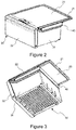
Figure 2 is a representative perspective view of a shelf and drawer positioned in the subject matter cooling device. -
Figure 3 is a representative perspective view of a shelf and drawer positioned in the subject matter cooling device. -
Figure 4 is a representative perspective view of the shelf positioned in the subject matter cooling device. -
Figure 5 is a representative perspective view of the housing provided on the shelf positioned in the subject matter cooling device. -
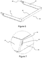
Figure 6 is a representative perspective view of the cover positioned in the subject matter cooling device. -
Figure 7 is a representative perspective view of the opening provided on the cover positioned in the subject matter cooling device. -
Figure 8 is a representative perspective view where the cover is assembled to the shelf positioned in the subject matter cooling device. -
Figure 9 is a representative perspective view where the cover is placed to the housing positioned in the subject matter cooling device. -
Figure 10 is a representative perspective view of the shelf and cover in the subject matter cooling device. -
Figure 11 is a perspective view where the cover is placed to the housing in the subject matter cooling device. - In this detailed description, the subject matter cooling device (10) is explained with references to examples without forming any restrictive effect only in order to make the subject more understandable.
- With reference to
Figures. 1-3 , the cooling device (10) essentially has at least one drawer (30) and at least one shelf (20) keep at different temperatures. Said drawer (30) is a storage chamber configured to have a depth by means of at least one front panel (32) and the drawer walls (31). The drawer (30) is essentially positioned at the lower vicinity of said shelf (20) and it can partially move horizontally. By means of this, the product can be put and removed from the drawer (30). In a probable embodiment of the present invention, the shelf (20) has at least one frame (21) and at least one extension part (22) at the side of said frame (21) facing the drawer (30). - In
Figures 2 and 3 , at least one cover (40) is positioned between said shelf (20) and said drawer (30) for at least partially preventing airflow in between. Said cover (40) at least partially encircles the drawer walls (31) and the front panel (32) positioned at the drawer (30) and provides isolation of the cooling device (10) from the inner part thereof. In order to realize this, as shown in theFigure 6 , the cover (40) has at least one rear wall (42) and at least one sidewall (41). There are two sidewalls (41), and said sidewalls (41) are connected to the rear wall (42) through one each ends thereof. Moreover, at least sidewalls (41) of the cover (40) are made of flexible material. - As shown in the
Figure 4 , said extension part (22) provided on the frame (21) is positioned in a manner extending along at least the sidewalls (41). As shown in theFigure 5 , at least one housing (24) and at least one fixation tab (27) are positioned on the extension part (22). The housing (24) is essentially an opening positioned on the extension part (22) in order to fix the cover (40) onto the shelf (20). The housing (24) is essentially closed to the outer medium and only the part of the housing (24) facing the drawer (30) is partially opened to the outer medium. The part of the housing (24) which is opened to the outer medium is the housing inlet (26). Said housing inlet (26) provides the cover (40) to enter into the housing (24). At least one carrier tab (23) is positioned in the vicinity of the housing inlet (26). Said carrier tab (23) prevents vertical movement of the cover (40) after the cover (40) engages to the housing (24). The side of the housing (24) facing the fixation tab (27) is defined as the housing base (25). The rear wall (42) is rested to the housing base (25) and the horizontal movement of the cover (40) is delimited. - In
Figure 8 , a representative perspective view where the cover (40) is assembled to the shelf (20) positioned in the subject matter cooling device (10) is given. Accordingly, the cover (40) is engaged to the housing (24) from a rear wall (42) side and is rested to the extension part (22) from the sidewalls (41). The fixation tab (27), positioned at the extension part (22), is engaged to at least one fixation housing (45) positioned at the side walls (41), and thereby the cover (40) is moved together with the shelf (20). - In
Figure 9 , a representative perspective view where the cover (40) is placed to the housing (24) positioned in the subject matter cooling device (10) is given. Accordingly, at least one opening (43), as shown in theFigure.7 , is essentially positioned on the rear wall (42) of the cover (40). At least one hanger part (44) is positioned essentially at the side of said opening (43) facing the shelf (20). While the cover (40) is assembled to the shelf (20), the fixation tab (27) passes through the opening (43) and said hanger part (44) is rested to the housing base (25). - In
Figure 10 , a representative perspective view of the shelf (20) and cover (40) in the subject matter cooling device (10) is given. Accordingly, as the hanger part (44) is rested to the housing base (25), the fixation housing (45) is aligned with the fixation tab (27) and they are engaged and locked to each other. - In
Figure 11 , a perspective view where the cover (40) is placed to the housing (24) in the subject matter cooling device (10) is given. Accordingly, the cover (40) engages to the housing (24) and is locked at the shelf (20) by means of the fixation tab (27). The separation of the cover (40) from the shelf (20) is provided by means of bending of the sidewalls (41). - The airflow, which may occur between the drawer (30) and the shelf (20), is prevented by means of the cover (40). The cover (40) can be easily fixed to and removed from the shelf (20). By means of this, the drawer (30) is kept at different temperatures when compared with the other parts of the cooling device (10), and energy saving and high efficiency are provided.
-
- 10
- Refrigerator
- 20
- Shelf
- 21
- Frame
- 22
- Extension part
- 23
- Carrier tab
- 24
- Housing
- 25
- Housing base
- 26
- Housing inlet
- 27
- Fixation tab
- 30
- Drawer
- 31
- Drawer wall
- 32
- Front panel
- 40
- Cover
- 41
- Side wall
- 42
- Rear wall
- 43
- Opening
- 44
- Hanger part
- 45
- Fixation housing
Claims (9)
- A cooling device (10) having at least one drawer (30) having a front panel (32) and pluralities of drawer walls (31),
at least one shelf (20) provided in the upper vicinity of said drawer (30),
at least one cover (40) which at least partially encircles the drawer walls (31) in order to at least partially close the openings which remain between said shelf (20) and said drawer walls (31), wherein for providing connection between said cover (40) and the shelf (20):
one (20, 40) of the shelf (20) and the cover (40) comprises at least one carrier tab (23), and the other one (20, 40) of the shelf (20) and the cover (40) comprises at least one opening (43) wherein said carrier tab (23) is at least partially placed. - The cooling device (10) according to claim 1, wherein one (20, 41) of the shelf (20) and at least one side wall (41) of the cover (40) comprises at least one fixation tab (27), and the other one (20, 41) of the shelf (20) and at least one side wall (41) of the cover (40) comprises at least one fixation housing (45) for housing the fixation tab (27).
- The cooling device (10) according to claim 1 or claim 2, wherein the carrier tab (23) and the opening (43) are provided in the vicinity of a rear wall (42) of the cover (40).
- The cooling device (10) according to claim 2 or claim 3, wherein the fixation tab (27) and the fixation housing (45) are provided in the vicinity of the front panel (32) of the drawer (30).
- The cooling device (10) according to any one of the preceding claims, wherein the cover (40) is provided in U-like form in a manner providing exposure of one each end of the side walls (41).
- The cooling device (10) according to any one of the preceding claims, wherein the carrier tab (23) is provided on an extension part (22) which extends from a frame (21) of the shelf (20) towards the side where the drawer (30) is provided.
- The cooling device (10) according to any one of the preceding claims, wherein the opening (43) is provided on the rear wall (42) of the cover (40) at a predetermined distance with respect to the edge of the rear wall (42) facing the shelf (20).
- The cooling device (10) according to any one of the claims 3-7, wherein at least one housing (24) is provided in the vicinity of the carrier tab (23) in a manner receiving a hanger part (44) defined between the opening (43) and the edge of the rear wall (42) of the cover (40) facing the shelf (20).
- The cooling device (10) according to claim 8, wherein the housing (24) comprises a housing base (25) where the hanger part (44) is rested into the housing (24) when the fixation housing (45) and the fixation tab (27) are mutually aligned.
Applications Claiming Priority (1)
| Application Number | Priority Date | Filing Date | Title |
|---|---|---|---|
| TR2019/14652A TR201914652A2 (en) | 2019-09-26 | 2019-09-26 | A COOLING DEVICE |
Publications (2)
| Publication Number | Publication Date |
|---|---|
| EP3798556A1 true EP3798556A1 (en) | 2021-03-31 |
| EP3798556B1 EP3798556B1 (en) | 2023-11-22 |
Family
ID=72561608
Family Applications (1)
| Application Number | Title | Priority Date | Filing Date |
|---|---|---|---|
| EP20196828.6A Active EP3798556B1 (en) | 2019-09-26 | 2020-09-18 | A cooling device |
Country Status (3)
| Country | Link |
|---|---|
| EP (1) | EP3798556B1 (en) |
| PL (1) | PL3798556T3 (en) |
| TR (1) | TR201914652A2 (en) |
Citations (3)
| Publication number | Priority date | Publication date | Assignee | Title |
|---|---|---|---|---|
| US4870836A (en) * | 1989-03-06 | 1989-10-03 | Amana Refrigeration, Inc. | Air flow control for glass top refrigerator container |
| CN104848647A (en) | 2015-05-29 | 2015-08-19 | 合肥华凌股份有限公司 | Refrigerator and drawer assembly thereof |
| DE102014219664A1 (en) * | 2014-09-29 | 2016-03-31 | BSH Hausgeräte GmbH | Refrigerating appliance with pull-out box |
-
2019
- 2019-09-26 TR TR2019/14652A patent/TR201914652A2/en unknown
-
2020
- 2020-09-18 PL PL20196828.6T patent/PL3798556T3/en unknown
- 2020-09-18 EP EP20196828.6A patent/EP3798556B1/en active Active
Patent Citations (3)
| Publication number | Priority date | Publication date | Assignee | Title |
|---|---|---|---|---|
| US4870836A (en) * | 1989-03-06 | 1989-10-03 | Amana Refrigeration, Inc. | Air flow control for glass top refrigerator container |
| DE102014219664A1 (en) * | 2014-09-29 | 2016-03-31 | BSH Hausgeräte GmbH | Refrigerating appliance with pull-out box |
| CN104848647A (en) | 2015-05-29 | 2015-08-19 | 合肥华凌股份有限公司 | Refrigerator and drawer assembly thereof |
Also Published As
| Publication number | Publication date |
|---|---|
| PL3798556T3 (en) | 2024-04-22 |
| TR201914652A2 (en) | 2021-04-21 |
| EP3798556B1 (en) | 2023-11-22 |
Similar Documents
| Publication | Publication Date | Title |
|---|---|---|
| US20140239792A1 (en) | Refrigerator appliance and a shelf assembly for the same | |
| US7665327B2 (en) | Chilled food storage area for refrigerated appliance | |
| EP3486585B1 (en) | Refrigerator | |
| US11788733B2 (en) | Cooking appliance | |
| US10724785B2 (en) | Cover for cooling fins of a refrigerator and refrigerator | |
| RU2007138616A (en) | CARTRIDGE FOR COOLING UNITS (OPTIONS) AND COOLED TRADE SHOWROOM | |
| EP3279592A1 (en) | Sealed crisper | |
| CN114688791A (en) | Sealing plate and partition wall for machine compartment | |
| US20180172340A1 (en) | Assembly for a domestic refrigeration appliance with a wire basket and domestic refrigeration appliance with such an assembly | |
| US20080203879A1 (en) | Refrigerator | |
| EP3798556B1 (en) | A cooling device | |
| US20180058750A1 (en) | Variable width deli cover | |
| JP4507685B2 (en) | Open showcase | |
| JP2002130933A (en) | Refrigerator | |
| JP2017003242A (en) | Cooling storage | |
| JP3371077B2 (en) | refrigerator | |
| JP7164355B2 (en) | refrigerator | |
| EP2938949B1 (en) | Cooling appliance having a drawer guide | |
| JP6998043B2 (en) | refrigerator | |
| JP2005114178A (en) | Showcase | |
| JP2020029973A (en) | refrigerator | |
| JP6223265B2 (en) | refrigerator | |
| JP2022037080A (en) | refrigerator | |
| JP2012063122A (en) | Refrigerator | |
| JP2021183903A (en) | refrigerator |
Legal Events
| Date | Code | Title | Description |
|---|---|---|---|
| PUAI | Public reference made under article 153(3) epc to a published international application that has entered the european phase |
Free format text: ORIGINAL CODE: 0009012 |
|
| STAA | Information on the status of an ep patent application or granted ep patent |
Free format text: STATUS: THE APPLICATION HAS BEEN PUBLISHED |
|
| AK | Designated contracting states |
Kind code of ref document: A1 Designated state(s): AL AT BE BG CH CY CZ DE DK EE ES FI FR GB GR HR HU IE IS IT LI LT LU LV MC MK MT NL NO PL PT RO RS SE SI SK SM TR |
|
| AX | Request for extension of the european patent |
Extension state: BA ME |
|
| STAA | Information on the status of an ep patent application or granted ep patent |
Free format text: STATUS: REQUEST FOR EXAMINATION WAS MADE |
|
| 17P | Request for examination filed |
Effective date: 20210930 |
|
| RBV | Designated contracting states (corrected) |
Designated state(s): AL AT BE BG CH CY CZ DE DK EE ES FI FR GB GR HR HU IE IS IT LI LT LU LV MC MK MT NL NO PL PT RO RS SE SI SK SM TR |
|
| GRAP | Despatch of communication of intention to grant a patent |
Free format text: ORIGINAL CODE: EPIDOSNIGR1 |
|
| STAA | Information on the status of an ep patent application or granted ep patent |
Free format text: STATUS: GRANT OF PATENT IS INTENDED |
|
| INTG | Intention to grant announced |
Effective date: 20230126 |
|
| GRAJ | Information related to disapproval of communication of intention to grant by the applicant or resumption of examination proceedings by the epo deleted |
Free format text: ORIGINAL CODE: EPIDOSDIGR1 |
|
| STAA | Information on the status of an ep patent application or granted ep patent |
Free format text: STATUS: REQUEST FOR EXAMINATION WAS MADE |
|
| INTC | Intention to grant announced (deleted) | ||
| GRAP | Despatch of communication of intention to grant a patent |
Free format text: ORIGINAL CODE: EPIDOSNIGR1 |
|
| STAA | Information on the status of an ep patent application or granted ep patent |
Free format text: STATUS: GRANT OF PATENT IS INTENDED |
|
| INTG | Intention to grant announced |
Effective date: 20230718 |
|
| GRAS | Grant fee paid |
Free format text: ORIGINAL CODE: EPIDOSNIGR3 |
|
| GRAA | (expected) grant |
Free format text: ORIGINAL CODE: 0009210 |
|
| STAA | Information on the status of an ep patent application or granted ep patent |
Free format text: STATUS: THE PATENT HAS BEEN GRANTED |
|
| AK | Designated contracting states |
Kind code of ref document: B1 Designated state(s): AL AT BE BG CH CY CZ DE DK EE ES FI FR GB GR HR HU IE IS IT LI LT LU LV MC MK MT NL NO PL PT RO RS SE SI SK SM TR |
|
| REG | Reference to a national code |
Ref country code: GB Ref legal event code: FG4D |
|
| REG | Reference to a national code |
Ref country code: CH Ref legal event code: EP Ref country code: DE Ref legal event code: R096 Ref document number: 602020021400 Country of ref document: DE |
|
| REG | Reference to a national code |
Ref country code: IE Ref legal event code: FG4D |
|
| REG | Reference to a national code |
Ref country code: LT Ref legal event code: MG9D |
|
| REG | Reference to a national code |
Ref country code: NL Ref legal event code: MP Effective date: 20231122 |
|
| PG25 | Lapsed in a contracting state [announced via postgrant information from national office to epo] |
Ref country code: GR Free format text: LAPSE BECAUSE OF FAILURE TO SUBMIT A TRANSLATION OF THE DESCRIPTION OR TO PAY THE FEE WITHIN THE PRESCRIBED TIME-LIMIT Effective date: 20240223 |
|
| PG25 | Lapsed in a contracting state [announced via postgrant information from national office to epo] |
Ref country code: IS Free format text: LAPSE BECAUSE OF FAILURE TO SUBMIT A TRANSLATION OF THE DESCRIPTION OR TO PAY THE FEE WITHIN THE PRESCRIBED TIME-LIMIT Effective date: 20240322 |
|
| PG25 | Lapsed in a contracting state [announced via postgrant information from national office to epo] |
Ref country code: LT Free format text: LAPSE BECAUSE OF FAILURE TO SUBMIT A TRANSLATION OF THE DESCRIPTION OR TO PAY THE FEE WITHIN THE PRESCRIBED TIME-LIMIT Effective date: 20231122 |
|
| REG | Reference to a national code |
Ref country code: AT Ref legal event code: MK05 Ref document number: 1634201 Country of ref document: AT Kind code of ref document: T Effective date: 20231122 |
|
| PG25 | Lapsed in a contracting state [announced via postgrant information from national office to epo] |
Ref country code: NL Free format text: LAPSE BECAUSE OF FAILURE TO SUBMIT A TRANSLATION OF THE DESCRIPTION OR TO PAY THE FEE WITHIN THE PRESCRIBED TIME-LIMIT Effective date: 20231122 |
|
| PG25 | Lapsed in a contracting state [announced via postgrant information from national office to epo] |
Ref country code: AT Free format text: LAPSE BECAUSE OF FAILURE TO SUBMIT A TRANSLATION OF THE DESCRIPTION OR TO PAY THE FEE WITHIN THE PRESCRIBED TIME-LIMIT Effective date: 20231122 |
|
| PG25 | Lapsed in a contracting state [announced via postgrant information from national office to epo] |
Ref country code: ES Free format text: LAPSE BECAUSE OF FAILURE TO SUBMIT A TRANSLATION OF THE DESCRIPTION OR TO PAY THE FEE WITHIN THE PRESCRIBED TIME-LIMIT Effective date: 20231122 |
|
| PG25 | Lapsed in a contracting state [announced via postgrant information from national office to epo] |
Ref country code: NL Free format text: LAPSE BECAUSE OF FAILURE TO SUBMIT A TRANSLATION OF THE DESCRIPTION OR TO PAY THE FEE WITHIN THE PRESCRIBED TIME-LIMIT Effective date: 20231122 Ref country code: LT Free format text: LAPSE BECAUSE OF FAILURE TO SUBMIT A TRANSLATION OF THE DESCRIPTION OR TO PAY THE FEE WITHIN THE PRESCRIBED TIME-LIMIT Effective date: 20231122 Ref country code: IS Free format text: LAPSE BECAUSE OF FAILURE TO SUBMIT A TRANSLATION OF THE DESCRIPTION OR TO PAY THE FEE WITHIN THE PRESCRIBED TIME-LIMIT Effective date: 20240322 Ref country code: GR Free format text: LAPSE BECAUSE OF FAILURE TO SUBMIT A TRANSLATION OF THE DESCRIPTION OR TO PAY THE FEE WITHIN THE PRESCRIBED TIME-LIMIT Effective date: 20240223 Ref country code: ES Free format text: LAPSE BECAUSE OF FAILURE TO SUBMIT A TRANSLATION OF THE DESCRIPTION OR TO PAY THE FEE WITHIN THE PRESCRIBED TIME-LIMIT Effective date: 20231122 Ref country code: BG Free format text: LAPSE BECAUSE OF FAILURE TO SUBMIT A TRANSLATION OF THE DESCRIPTION OR TO PAY THE FEE WITHIN THE PRESCRIBED TIME-LIMIT Effective date: 20240222 Ref country code: AT Free format text: LAPSE BECAUSE OF FAILURE TO SUBMIT A TRANSLATION OF THE DESCRIPTION OR TO PAY THE FEE WITHIN THE PRESCRIBED TIME-LIMIT Effective date: 20231122 Ref country code: PT Free format text: LAPSE BECAUSE OF FAILURE TO SUBMIT A TRANSLATION OF THE DESCRIPTION OR TO PAY THE FEE WITHIN THE PRESCRIBED TIME-LIMIT Effective date: 20240322 |
|
| PG25 | Lapsed in a contracting state [announced via postgrant information from national office to epo] |
Ref country code: SE Free format text: LAPSE BECAUSE OF FAILURE TO SUBMIT A TRANSLATION OF THE DESCRIPTION OR TO PAY THE FEE WITHIN THE PRESCRIBED TIME-LIMIT Effective date: 20231122 Ref country code: RS Free format text: LAPSE BECAUSE OF FAILURE TO SUBMIT A TRANSLATION OF THE DESCRIPTION OR TO PAY THE FEE WITHIN THE PRESCRIBED TIME-LIMIT Effective date: 20231122 Ref country code: NO Free format text: LAPSE BECAUSE OF FAILURE TO SUBMIT A TRANSLATION OF THE DESCRIPTION OR TO PAY THE FEE WITHIN THE PRESCRIBED TIME-LIMIT Effective date: 20240222 Ref country code: LV Free format text: LAPSE BECAUSE OF FAILURE TO SUBMIT A TRANSLATION OF THE DESCRIPTION OR TO PAY THE FEE WITHIN THE PRESCRIBED TIME-LIMIT Effective date: 20231122 Ref country code: HR Free format text: LAPSE BECAUSE OF FAILURE TO SUBMIT A TRANSLATION OF THE DESCRIPTION OR TO PAY THE FEE WITHIN THE PRESCRIBED TIME-LIMIT Effective date: 20231122 |
|
| PG25 | Lapsed in a contracting state [announced via postgrant information from national office to epo] |
Ref country code: DK Free format text: LAPSE BECAUSE OF FAILURE TO SUBMIT A TRANSLATION OF THE DESCRIPTION OR TO PAY THE FEE WITHIN THE PRESCRIBED TIME-LIMIT Effective date: 20231122 |
|
| PG25 | Lapsed in a contracting state [announced via postgrant information from national office to epo] |
Ref country code: CZ Free format text: LAPSE BECAUSE OF FAILURE TO SUBMIT A TRANSLATION OF THE DESCRIPTION OR TO PAY THE FEE WITHIN THE PRESCRIBED TIME-LIMIT Effective date: 20231122 |
|
| PG25 | Lapsed in a contracting state [announced via postgrant information from national office to epo] |
Ref country code: SK Free format text: LAPSE BECAUSE OF FAILURE TO SUBMIT A TRANSLATION OF THE DESCRIPTION OR TO PAY THE FEE WITHIN THE PRESCRIBED TIME-LIMIT Effective date: 20231122 |
|
| PG25 | Lapsed in a contracting state [announced via postgrant information from national office to epo] |
Ref country code: SM Free format text: LAPSE BECAUSE OF FAILURE TO SUBMIT A TRANSLATION OF THE DESCRIPTION OR TO PAY THE FEE WITHIN THE PRESCRIBED TIME-LIMIT Effective date: 20231122 Ref country code: SK Free format text: LAPSE BECAUSE OF FAILURE TO SUBMIT A TRANSLATION OF THE DESCRIPTION OR TO PAY THE FEE WITHIN THE PRESCRIBED TIME-LIMIT Effective date: 20231122 Ref country code: RO Free format text: LAPSE BECAUSE OF FAILURE TO SUBMIT A TRANSLATION OF THE DESCRIPTION OR TO PAY THE FEE WITHIN THE PRESCRIBED TIME-LIMIT Effective date: 20231122 Ref country code: IT Free format text: LAPSE BECAUSE OF FAILURE TO SUBMIT A TRANSLATION OF THE DESCRIPTION OR TO PAY THE FEE WITHIN THE PRESCRIBED TIME-LIMIT Effective date: 20231122 Ref country code: EE Free format text: LAPSE BECAUSE OF FAILURE TO SUBMIT A TRANSLATION OF THE DESCRIPTION OR TO PAY THE FEE WITHIN THE PRESCRIBED TIME-LIMIT Effective date: 20231122 Ref country code: DK Free format text: LAPSE BECAUSE OF FAILURE TO SUBMIT A TRANSLATION OF THE DESCRIPTION OR TO PAY THE FEE WITHIN THE PRESCRIBED TIME-LIMIT Effective date: 20231122 Ref country code: CZ Free format text: LAPSE BECAUSE OF FAILURE TO SUBMIT A TRANSLATION OF THE DESCRIPTION OR TO PAY THE FEE WITHIN THE PRESCRIBED TIME-LIMIT Effective date: 20231122 |
|
| REG | Reference to a national code |
Ref country code: DE Ref legal event code: R097 Ref document number: 602020021400 Country of ref document: DE |
|
| PLBE | No opposition filed within time limit |
Free format text: ORIGINAL CODE: 0009261 |
|
| STAA | Information on the status of an ep patent application or granted ep patent |
Free format text: STATUS: NO OPPOSITION FILED WITHIN TIME LIMIT |
|
| PG25 | Lapsed in a contracting state [announced via postgrant information from national office to epo] |
Ref country code: SI Free format text: LAPSE BECAUSE OF FAILURE TO SUBMIT A TRANSLATION OF THE DESCRIPTION OR TO PAY THE FEE WITHIN THE PRESCRIBED TIME-LIMIT Effective date: 20231122 |
|
| 26N | No opposition filed |
Effective date: 20240823 |
|
| PG25 | Lapsed in a contracting state [announced via postgrant information from national office to epo] |
Ref country code: SI Free format text: LAPSE BECAUSE OF FAILURE TO SUBMIT A TRANSLATION OF THE DESCRIPTION OR TO PAY THE FEE WITHIN THE PRESCRIBED TIME-LIMIT Effective date: 20231122 |
|
| PG25 | Lapsed in a contracting state [announced via postgrant information from national office to epo] |
Ref country code: MC Free format text: LAPSE BECAUSE OF FAILURE TO SUBMIT A TRANSLATION OF THE DESCRIPTION OR TO PAY THE FEE WITHIN THE PRESCRIBED TIME-LIMIT Effective date: 20231122 |
|
| REG | Reference to a national code |
Ref country code: CH Ref legal event code: PL |
|
| PG25 | Lapsed in a contracting state [announced via postgrant information from national office to epo] |
Ref country code: LU Free format text: LAPSE BECAUSE OF NON-PAYMENT OF DUE FEES Effective date: 20240918 |
|
| GBPC | Gb: european patent ceased through non-payment of renewal fee |
Effective date: 20240918 |
|
| PG25 | Lapsed in a contracting state [announced via postgrant information from national office to epo] |
Ref country code: GB Free format text: LAPSE BECAUSE OF NON-PAYMENT OF DUE FEES Effective date: 20240918 |
|
| REG | Reference to a national code |
Ref country code: BE Ref legal event code: MM Effective date: 20240930 |
|
| PG25 | Lapsed in a contracting state [announced via postgrant information from national office to epo] |
Ref country code: BE Free format text: LAPSE BECAUSE OF NON-PAYMENT OF DUE FEES Effective date: 20240930 |
|
| PG25 | Lapsed in a contracting state [announced via postgrant information from national office to epo] |
Ref country code: FR Free format text: LAPSE BECAUSE OF NON-PAYMENT OF DUE FEES Effective date: 20240930 |
|
| PG25 | Lapsed in a contracting state [announced via postgrant information from national office to epo] |
Ref country code: CH Free format text: LAPSE BECAUSE OF NON-PAYMENT OF DUE FEES Effective date: 20240930 |
|
| PG25 | Lapsed in a contracting state [announced via postgrant information from national office to epo] |
Ref country code: IE Free format text: LAPSE BECAUSE OF NON-PAYMENT OF DUE FEES Effective date: 20240918 |
|
| PG25 | Lapsed in a contracting state [announced via postgrant information from national office to epo] |
Ref country code: FI Free format text: LAPSE BECAUSE OF FAILURE TO SUBMIT A TRANSLATION OF THE DESCRIPTION OR TO PAY THE FEE WITHIN THE PRESCRIBED TIME-LIMIT Effective date: 20231122 |
|
| PGFP | Annual fee paid to national office [announced via postgrant information from national office to epo] |
Ref country code: DE Payment date: 20250930 Year of fee payment: 6 |
|
| PGFP | Annual fee paid to national office [announced via postgrant information from national office to epo] |
Ref country code: PL Payment date: 20250905 Year of fee payment: 6 Ref country code: TR Payment date: 20250911 Year of fee payment: 6 |
|
| PG25 | Lapsed in a contracting state [announced via postgrant information from national office to epo] |
Ref country code: CY Free format text: LAPSE BECAUSE OF FAILURE TO SUBMIT A TRANSLATION OF THE DESCRIPTION OR TO PAY THE FEE WITHIN THE PRESCRIBED TIME-LIMIT; INVALID AB INITIO Effective date: 20200918 |
|
| PG25 | Lapsed in a contracting state [announced via postgrant information from national office to epo] |
Ref country code: HU Free format text: LAPSE BECAUSE OF FAILURE TO SUBMIT A TRANSLATION OF THE DESCRIPTION OR TO PAY THE FEE WITHIN THE PRESCRIBED TIME-LIMIT; INVALID AB INITIO Effective date: 20200918 |