EP3798523B1 - Heat exchanger applied to ceiling air conditioner and ceiling air conditioner - Google Patents
Heat exchanger applied to ceiling air conditioner and ceiling air conditioner Download PDFInfo
- Publication number
- EP3798523B1 EP3798523B1 EP19910848.1A EP19910848A EP3798523B1 EP 3798523 B1 EP3798523 B1 EP 3798523B1 EP 19910848 A EP19910848 A EP 19910848A EP 3798523 B1 EP3798523 B1 EP 3798523B1
- Authority
- EP
- European Patent Office
- Prior art keywords
- heat exchange
- exchange part
- air conditioner
- cassette type
- type air
- Prior art date
- Legal status (The legal status is an assumption and is not a legal conclusion. Google has not performed a legal analysis and makes no representation as to the accuracy of the status listed.)
- Active
Links
Images
Classifications
-
- F—MECHANICAL ENGINEERING; LIGHTING; HEATING; WEAPONS; BLASTING
- F24—HEATING; RANGES; VENTILATING
- F24F—AIR-CONDITIONING; AIR-HUMIDIFICATION; VENTILATION; USE OF AIR CURRENTS FOR SCREENING
- F24F1/00—Room units for air-conditioning, e.g. separate or self-contained units or units receiving primary air from a central station
- F24F1/0007—Indoor units, e.g. fan coil units
- F24F1/0059—Indoor units, e.g. fan coil units characterised by heat exchangers
- F24F1/0063—Indoor units, e.g. fan coil units characterised by heat exchangers by the mounting or arrangement of the heat exchangers
-
- F—MECHANICAL ENGINEERING; LIGHTING; HEATING; WEAPONS; BLASTING
- F24—HEATING; RANGES; VENTILATING
- F24F—AIR-CONDITIONING; AIR-HUMIDIFICATION; VENTILATION; USE OF AIR CURRENTS FOR SCREENING
- F24F1/00—Room units for air-conditioning, e.g. separate or self-contained units or units receiving primary air from a central station
- F24F1/0007—Indoor units, e.g. fan coil units
- F24F1/0059—Indoor units, e.g. fan coil units characterised by heat exchangers
- F24F1/0067—Indoor units, e.g. fan coil units characterised by heat exchangers by the shape of the heat exchangers or of parts thereof, e.g. of their fins
Definitions
- the present disclosure relates to the field of air conditioner technologies, and more particularly, to a heat exchanger applied to a cassette type air conditioner and a cassette type air conditioner.
- Cassette type air conditioners also known as ceiling air conditioners, are a type of commercial air conditioners. Compared with household air conditioners, the cassette type air conditioners have better stability, stronger cooling capacity and more controllable temperature, and are mostly used in some offices and shops.
- an intermediate heat exchange part of the cassette type air conditioner is a planar structure for supplying air to rooms, which results in poor heat dissipation of an air supply system of the cassette type air conditioner, thereby reducing heat exchange efficiency, wasting electric energy and failing to meet user needs.
- EP 1 382 917 A1 discloses a cassette type air conditioner.
- the indoor unit of the air conditioner comprises a casing, a heat exchanger, and a turbofan.
- air passageways that extend from the turbofan 40 to the outlets via the heat exchanger 30
- air passageways which extend from the turbofan to the outlet and oppose the direction of the wind from the turbofan, are narrower than other air passageways.
- US 6 877 331 B2 discloses an air conditioner that is built into or hung from a ceiling and which employs a cross fin type of heat exchanger, in which the effective length of the heat exchanger is increased without increasing the size of the casing of the indoor unit.
- An indoor unit has a casing that supports the components of the indoor unit and in which an air suction port and air discharge ports are formed, a centrifugal fan disposed inside the casing for taking in air from the air suction port and discharging air out to the sides thereof, and a cross fin type of heat exchanger for exchanging heat with the air discharged from the centrifugal fan and disposed so that it surrounds the centrifugal fan.
- the heat exchanger has a plurality of concave portions that are formed such that they are near the outer circumferential portion of the centrifugal fan, and a plurality of convex portions that are formed such that the extend away from the outer circumferential portion of the centrifugal fan.
- JP H03 156221 discloses a heat exchanger comprises a multilayer stack of fin units at predetermined intervals.
- Each of the fin units comprises a stack of net form fins electric heating tube fitting holes formed between the fins and a plurality of flexible electric heating tubes fitted in the holes.
- the heat exchanger is installed in the state of being bent up and down across an air passage by utilizing a plurality of support rods arranged at a predetermined vertical spacing so that bent projected parts and bent recessed parts are oriented in the direction of the air passage.
- An airflow is introduced from an air suction port, and heat exchange between Joule heat generated according to a current flowing through a heater wire in the heating tubes and air passed through the tubes is carried out through the fins with extremely high efficiency.
- the present invention provides a cassette type air conditioner comprising a heat exchanger according to claim 1.
- an air supply system of the cassette type air conditioner can dissipate heat more smoothly, thereby improving heat exchange efficiency, saving more electric energy and enabling customers to use better.
- 1 side heat exchange part; 2: intermediate heat exchange part; 21: first intermediate heat exchange part; 22: second intermediate heat exchange part; 11: first side heat exchange part; 12: second side heat exchange part.
- orientations or position relationships indicated by terms “longitudinal”, “lateral”, “up”, “down”, “front”, “behind”, “left”, “right”, “vertical”, “horizontal”, “top”, “bottom”, “inside”, “outside”, and the like are orientations or position relationships shown based on the accompanying drawings, and are merely used for describing the present disclosure and for description simplicity, instead of indicating or implying that an indicated device or element need to provide in a specific orientation, or need to be constructed and operated in a specific orientation, therefore, the orientations or position relationships cannot be understood as a limitation of the present disclosure.
- connection may be a mechanical connection or an electrical connection, or may also be an internal connection between two elements, or may be connected direct connection, or may also be an indirect connection based on an intermediate medium.
- connection may be a mechanical connection or an electrical connection, or may also be an internal connection between two elements, or may be connected direct connection, or may also be an indirect connection based on an intermediate medium.
- a term "a plurality of" indicates two or more unless otherwise explicitly specified.
- a character "/" indicates an “or” relationship between objects before and after the character.
- A/B indicates A or B.
- a and/or B may represent three relationships: A, or B, or A and B.
- a heat exchanger applied to a cassette type air conditioner including two side heat exchange parts 1 provided on two sides and at an angle to each other; and an intermediate heat exchange part 2 provided between the two side heat exchange parts 1, wherein the intermediate heat exchange part 2 has a concave structure facing away from the angle between the two side heat exchange parts.
- the two side heat exchange parts 1 are the air inlet part of the cassette type air conditioner, and the intermediate heat exchange part 2 is the air outlet part of the cassette type air conditioner.
- the intermediate heat exchange part 2 includes a first intermediate heat exchange part 21 and a second intermediate heat exchange part 22, and the first intermediate heat exchange part 21 and the second intermediate heat exchange part 22 can be a symmetrical structure.
- the two side heat exchange parts 1 include a first side heat exchange part 11 and a second side heat exchange part 12, and the first side heat exchange part 11 and the second side heat exchange part 12 can be a symmetrical structure.
- the two side heat exchange parts 1 are provided on both sides of the intermediate heat exchange part 2.
- the two side heat exchange parts 1 are provided at an angle to each other, which means that if one of the two side heat exchange parts 1 (i.e., the first side heat exchange part 11) is not moved, and the other of the two side heat exchange parts 1 (i.e., the second side heat exchange part 12) is moved in a direction of the first side heat exchange part 11, when the first side heat exchange part 11 and the second side heat exchange part 12 intersect, the plane where the first side heat exchange part 11 is located and the plane where the second side heat exchange part 12 is located cannot completely coincide, that is, the two planes are at a certain angle, which is not limited here.
- both the two side heat exchangers 1 and the intermediate heat exchange part 2 can be provided with vent holes.
- the two side heat exchange parts 1 are provided at a certain angle, that is, the two side heat exchange parts 1 are not in the same plane, by using Computational Fluid Dynamics CFD to simulate the wind speed field, when the first intermediate heat exchange part 21 and the second intermediate heat exchange part 22 are in the same plane, that is, an angle between the first intermediate heat exchange part 21 and the second intermediate heat exchange part 22 is 180°, an angle between the first intermediate heat exchange part 21 and the first side heat exchange part 11 is adjusted to 144.9°, and an angle between the second intermediate heat exchange part 22 and the second side heat exchange part 12 is adjusted to 144.8°; at this time, when the wind speeds entering through the first side heat exchange part 11 and the second side heat exchange part 12 are 1.6m/s, the measured wind speeds discharged from the first intermediate heat exchange part 21 and the second intermediate heat exchange part 22 are only 0.6m/s, which indicates
- a concave depth of the concave structure of the intermediate heat exchange part 2 is 0mm, when the first intermediate heat exchange part 21 and the second intermediate heat exchange part 22 are in the same plane, that is, the angle between the first intermediate heat exchange part 21 and the second intermediate heat exchange part 22 is 180°, the angle between the first intermediate heat exchange part 21 and the first side heat exchange part 11 is adjusted to 144.9°, and the angle between the second intermediate heat exchange part 22 and the second side heat exchange part 12 is adjusted to 144.8°; at this time, when the wind speeds entering through the first side heat exchange part 11 and the second side heat exchange part 12 are 1.6m/s, the measured wind speeds discharged from the first intermediate heat exchange part 21 and the second intermediate heat exchange part 22 are only 0.6m/s, which indicates that when the first intermediate heat exchange part 21 and the second intermediate heat exchange part 22 is in the same plane, the internal circulation of the cassette type air conditioner is not smooth, and heat exchange efficiency is relatively low, thereby wasting electric energy.
- the concave depth of the concave structure of the intermediate heat exchange part 2 is 152mm, and the angle between the first intermediate heat exchange part 21 and the second intermediate heat exchange part 22 is 103°; at this time, when the wind speeds entering through the first side heat exchange part 11 and the second side heat exchange part 12 are 1.48m/s, the measured wind speeds discharged from the first intermediate heat exchange part 21 and the second intermediate heat exchange part 22 are 1.26m/s and 1.27m/s, respectively. Therefore, by changing the structure of the heat exchange part of the heat exchanger of the cassette type air conditioner, an air supply system of the cassette type air conditioner can dissipate heat more smoothly, thereby improving heat exchange efficiency, saving more electric energy and enabling customers to use better.
- a maximum width of the concave structure of the intermediate heat exchange part 2 is 127mm to 162mm. It is indicated by experiments that when the width of the concave structure of the intermediate heat exchange part 2 is less than 127mm or greater than 162mm, the wind speed discharged from the intermediate heat exchange part 2 will decrease, and heat exchange efficiency will decrease. Therefore, the width of the concave structure of the intermediate heat exchange part 2 is limited to 127mm to 162mm. Therefore, by changing the structure of the heat exchange part of the heat exchanger of the cassette type air conditioner, an air supply system of the cassette type air conditioner can dissipate heat more smoothly, thereby improving heat exchange efficiency, saving more electric energy and enabling customers to use better.
- the concave side of the intermediate heat exchange part 2 is perpendicular to the side heat exchange part on a side corresponding to the concave side.
- the concave side of the intermediate heat exchange part 2 is smoothly connected with the side heat exchange part on the side corresponding to the concave side through an arc-shaped section.
- the concave side of the intermediate heat exchange part 2 can be smoothly connected with the side heat exchange part on the side corresponding to the concave side through an arc-shaped section. Since the resistance of the air on a streamlined surface is relatively small, the formation of vortices can be avoided. Therefore, the resistance when the air flows is greatly reduced, at the same speed of the air inlet, the air outlet becomes smoother. Therefore, by changing the structure of the heat exchange part of the heat exchanger of the cassette type air conditioner, an air supply system of the cassette type air conditioner can dissipate heat more smoothly, thereby improving heat exchange efficiency, saving more electric energy and enabling customers to use better.
- the concave side of each side of the intermediate heat exchange part 2 and the side heat exchange part 1 on a side corresponding to the concave side are of an integral structure.
- the integral structure can make the heat exchange part of the cassette type air conditioner as a whole, thereby improving the stability, reducing the failure rate, and avoiding the friction consumption among components.
- the intermediate heat exchange part 2 and the two side heat exchange parts 1 will inevitably generate some tiny vibrations and flash cracks, not only impurities easily enter the body of the air conditioner from tiny gaps, but also cause wear among the components, therefore, the first intermediate heat exchange part 21 and the first side heat exchange part 11 are manufactured as the integral structure, and the second intermediate heat exchange part 22 and the second side heat exchange part 12 are also manufactured as the integral structure. Therefore, by changing the structure of the heat exchange part of the heat exchanger of the cassette type air conditioner, an air supply system of the cassette type air conditioner can dissipate heat more smoothly, thereby improving heat exchange efficiency, saving more electric energy and enabling customers to use better.
- the heat exchanger has a symmetrical structure.
- the intermediate heat exchange part 2 includes a first intermediate heat exchange part 21 and a second intermediate heat exchange part 22, and the first intermediate heat exchange part 21 and the second intermediate heat exchange part 22 can be a symmetrical structure.
- the two side heat exchange parts 1 include a first side heat exchange part 11 and a second side heat exchange part 12, and the first side heat exchange part 11 and the second side heat exchange part 12 can be a symmetrical structure. Therefore, by changing the structure of the heat exchange part of the heat exchanger of the cassette type air conditioner, an air supply system of the cassette type air conditioner can dissipate heat more smoothly, thereby improving heat exchange efficiency, saving more electric energy and enabling customers to use better.
- the present invention provides a cassette type air conditioner, including the above heat exchanger, wherein the two side heat exchange parts 1 of the heat exchanger corresponds to an air inlet of the cassette type air conditioner, and the intermediate heat exchange part 2 corresponds to an air outlet of the cassette type air conditioner.
- the heat exchanger includes two side heat exchange parts 1 provided on two sides and at an angle to each other; and an intermediate heat exchange part 2 provided between the two side heat exchange parts 1, wherein the intermediate heat exchange part 2 has a concave structure facing away from the angle between the two side heat exchange parts. Therefore, by changing the structure of the heat exchange part of the heat exchanger of the cassette type air conditioner, an air supply system of the cassette type air conditioner can dissipate heat more smoothly, thereby improving heat exchange efficiency, saving more electric energy and enabling customers to use better.
- the intermediate heat exchange part 2 includes a first intermediate heat exchange part 21 and a second intermediate heat exchange part 22, and the first intermediate heat exchange part 21 and the second intermediate heat exchange part 22 can be a symmetrical structure.
- the two side heat exchange parts 1 include a first side heat exchange part 11 and a second side heat exchange part 12, and the first side heat exchange part 11 and the second side heat exchange part 12 can be a symmetrical structure. Therefore, by changing the structure of the heat exchange part of the heat exchanger of the cassette type air conditioner, an air supply system of the cassette type air conditioner can dissipate heat more smoothly, thereby improving heat exchange efficiency, saving more electric energy and enabling customers to use better.
- the concave side of the intermediate heat exchange part 2 can be smoothly connected with the side heat exchange part on the side corresponding to the concave side through an arc-shaped section. Since the resistance of the air on a streamlined surface is relatively small, the formation of vortices can be avoided. Therefore, the resistance when the air flows is greatly reduced, at the same speed of the air inlet, the air outlet becomes smoother. Therefore, by changing the structure of the heat exchange part of the heat exchanger of the cassette type air conditioner, an air supply system of the cassette type air conditioner can dissipate heat more smoothly, thereby improving heat exchange efficiency, saving more electric energy and enabling customers to use better.
Landscapes
- Engineering & Computer Science (AREA)
- Physics & Mathematics (AREA)
- Thermal Sciences (AREA)
- Chemical & Material Sciences (AREA)
- Combustion & Propulsion (AREA)
- Mechanical Engineering (AREA)
- General Engineering & Computer Science (AREA)
- Air Filters, Heat-Exchange Apparatuses, And Housings Of Air-Conditioning Units (AREA)
- Other Air-Conditioning Systems (AREA)
- Heat-Exchange Devices With Radiators And Conduit Assemblies (AREA)
Description
- The present disclosure relates to the field of air conditioner technologies, and more particularly, to a heat exchanger applied to a cassette type air conditioner and a cassette type air conditioner.
- Cassette type air conditioners, also known as ceiling air conditioners, are a type of commercial air conditioners. Compared with household air conditioners, the cassette type air conditioners have better stability, stronger cooling capacity and more controllable temperature, and are mostly used in some offices and shops.
- During the implementation of the embodiments of the present disclosure, it is found that at least the following problems exist in related arts:
an intermediate heat exchange part of the cassette type air conditioner is a planar structure for supplying air to rooms, which results in poor heat dissipation of an air supply system of the cassette type air conditioner, thereby reducing heat exchange efficiency, wasting electric energy and failing to meet user needs. -
EP 1 382 917 A1 discloses a cassette type air conditioner. The indoor unit of the air conditioner comprises a casing, a heat exchanger, and a turbofan. Among the air passageways that extend from the turbofan 40 to the outlets via the heat exchanger 30, air passageways, which extend from the turbofan to the outlet and oppose the direction of the wind from the turbofan, are narrower than other air passageways. -
US 6 877 331 B2 discloses an air conditioner that is built into or hung from a ceiling and which employs a cross fin type of heat exchanger, in which the effective length of the heat exchanger is increased without increasing the size of the casing of the indoor unit. An indoor unit has a casing that supports the components of the indoor unit and in which an air suction port and air discharge ports are formed, a centrifugal fan disposed inside the casing for taking in air from the air suction port and discharging air out to the sides thereof, and a cross fin type of heat exchanger for exchanging heat with the air discharged from the centrifugal fan and disposed so that it surrounds the centrifugal fan. The heat exchanger has a plurality of concave portions that are formed such that they are near the outer circumferential portion of the centrifugal fan, and a plurality of convex portions that are formed such that the extend away from the outer circumferential portion of the centrifugal fan. -
JP H03 156221 - In order to have a basic understanding of some aspects of disclosed embodiments, a brief summary is given below. The summary is not a general comment, nor is it intended to identify key/important constituent elements or to describe the scope of protection of these embodiments, but serves as a preamble to the following detailed description.
- The present invention provides a cassette type air conditioner comprising a heat exchanger according to claim 1.
- Embodiments of the invention are defined in the dependent claims.
- Some technical solutions provided by the embodiments of the present disclosure may achieve the following technical effects:
- by changing the structure of the heat exchange part of the heat exchanger of the cassette type air conditioner, an air supply system of the cassette type air conditioner can dissipate heat more smoothly, thereby improving heat exchange efficiency, saving more electric energy and enabling customers to use better.
- The above general description and the following description are exemplary and explanatory only and are not intended to limit the scope of protection as defined by the claims.
- One or more embodiments are exemplarily described by corresponding accompanying drawings. These exemplary descriptions and drawings do not limit the embodiments. Elements with same reference numerals in the drawings are shown as similar elements. The drawings do not constitute a scale limitation, and in which:
-
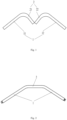
Fig. 1 is a schematic structural diagram of a heat exchanger applied to a cassette type air conditioner according to an embodiment of the present invention; -
Fig. 2 is a schematic structural diagram of a heat exchanger applied to a cassette type air conditioner not according to the present invention. - 1: side heat exchange part; 2: intermediate heat exchange part; 21: first intermediate heat exchange part; 22: second intermediate heat exchange part; 11: first side heat exchange part; 12: second side heat exchange part.
- The following description and accompanying drawings fully illustrate the specific implementation solutions of the present disclosure so that a person skilled in the art can practice them. Parts and characteristics of some implementation solutions may be included in or replace parts and characteristics of other implementation solutions. As used herein, terms such as "first" and "second" are merely for distinguishing one entity or operation from another entity or operation and do not require or imply any actual relationship or sequence among these entities or operations. In fact, a first element can also be called a second element, and vice versa. Moreover, terms such as "comprise" and "include" or any other variants indicate a non-exclusive inclusion, so that a process, method, or device including a series of elements not only include these elements, but also include other elements not explicitly listed. Without further restrictions, the element defined by the statement "includes a/an ..." does not exclude the existence of other identical elements in the process, method or device that includes the element. As used herein, each embodiment is described progressively, and contents focally described in each embodiment are different from those in other embodiments. The same or similar parts among each of the embodiments may be referred to each other.
- As used herein, orientations or position relationships indicated by terms "longitudinal", "lateral", "up", "down", "front", "behind", "left", "right", "vertical", "horizontal", "top", "bottom", "inside", "outside", and the like are orientations or position relationships shown based on the accompanying drawings, and are merely used for describing the present disclosure and for description simplicity, instead of indicating or implying that an indicated device or element need to provide in a specific orientation, or need to be constructed and operated in a specific orientation, therefore, the orientations or position relationships cannot be understood as a limitation of the present disclosure. In the description of the present disclosure, terms "installation", "joint", "connection" should be understood in a broad sense unless otherwise explicitly specified and limited, for example, "connection" may be a mechanical connection or an electrical connection, or may also be an internal connection between two elements, or may be connected direct connection, or may also be an indirect connection based on an intermediate medium. For a person of ordinary skill in the art, a specific meaning of the foregoing terms may be understood according to a specific situation.
- As used herein, a term "a plurality of" indicates two or more unless otherwise explicitly specified.
- As used herein, a character "/" indicates an "or" relationship between objects before and after the character. For example, A/B indicates A or B.
- As used herein, a term "and/or" describes an association relationship for depicting associated objects and represents that three relationships may exist. For example, A and/or B may represent three relationships: A, or B, or A and B.
- There is provided a heat exchanger applied to a cassette type air conditioner, including two side heat exchange parts 1 provided on two sides and at an angle to each other; and an intermediate
heat exchange part 2 provided between the two side heat exchange parts 1, wherein the intermediateheat exchange part 2 has a concave structure facing away from the angle between the two side heat exchange parts. - The two side heat exchange parts 1 are the air inlet part of the cassette type air conditioner, and the intermediate
heat exchange part 2 is the air outlet part of the cassette type air conditioner. - Optionally, the intermediate
heat exchange part 2 includes a first intermediateheat exchange part 21 and a second intermediateheat exchange part 22, and the first intermediateheat exchange part 21 and the second intermediateheat exchange part 22 can be a symmetrical structure. The two side heat exchange parts 1 include a first side heat exchange part 11 and a second sideheat exchange part 12, and the first side heat exchange part 11 and the second sideheat exchange part 12 can be a symmetrical structure. - In the present invention, the two side heat exchange parts 1 are provided on both sides of the intermediate
heat exchange part 2. The two side heat exchange parts 1 are provided at an angle to each other, which means that if one of the two side heat exchange parts 1 (i.e., the first side heat exchange part 11) is not moved, and the other of the two side heat exchange parts 1 (i.e., the second side heat exchange part 12) is moved in a direction of the first side heat exchange part 11, when the first side heat exchange part 11 and the second sideheat exchange part 12 intersect, the plane where the first side heat exchange part 11 is located and the plane where the second sideheat exchange part 12 is located cannot completely coincide, that is, the two planes are at a certain angle, which is not limited here. - Optionally, both the two side heat exchangers 1 and the intermediate
heat exchange part 2 can be provided with vent holes. When the wind enters through the vent holes of the two side heat exchangers 1, since the two side heat exchange parts 1 are provided at a certain angle, that is, the two side heat exchange parts 1 are not in the same plane, by using Computational Fluid Dynamics CFD to simulate the wind speed field, when the first intermediate heat exchangepart 21 and the second intermediateheat exchange part 22 are in the same plane, that is, an angle between the first intermediateheat exchange part 21 and the second intermediateheat exchange part 22 is 180°, an angle between the first intermediateheat exchange part 21 and the first side heat exchange part 11 is adjusted to 144.9°, and an angle between the second intermediateheat exchange part 22 and the second sideheat exchange part 12 is adjusted to 144.8°; at this time, when the wind speeds entering through the first side heat exchange part 11 and the second sideheat exchange part 12 are 1.6m/s, the measured wind speeds discharged from the first intermediateheat exchange part 21 and the second intermediateheat exchange part 22 are only 0.6m/s, which indicates that when the first intermediate heat exchangepart 21 and the second intermediateheat exchange part 22 is in the same plane, an internal circulation of the cassette type air conditioner is not smooth, and heat exchange efficiency is relatively low, thereby wasting electric energy. By adjusting the angle between the first intermediateheat exchange part 21 and the second intermediateheat exchange part 22 to 90° and keeping the angle between the first side heat exchange part 11 and the second sideheat exchange part 12 unchanged, when the angle between the first intermediateheat exchange part 21 and the second intermediateheat exchange part 22 is 90°, the angle between the first intermediateheat exchange part 21 and the first side heat exchange part 11 is adjusted to 99.9°, and the angle between the second intermediateheat exchange part 22 and the second sideheat exchange part 12 is adjusted to 99.8°; at this time, when the wind speeds entering through the first side heat exchange part 11 and the second sideheat exchange part 12 are 1.48m/s, the measured wind speeds discharged from the first intermediateheat exchange part 21 and the second intermediateheat exchange part 22 are 1.32m/s and 1.33m/s, respectively. Therefore, by changing the structure of the heat exchange part of the heat exchanger of the cassette type air conditioner, an air supply system of the cassette type air conditioner can dissipate heat more smoothly, thereby improving heat exchange efficiency, saving more electric energy and enabling customers to use better. - Optionally, when an angle between two concave sides of the concave structure of the intermediate
heat exchange part 2 is 141°, when the wind speeds entering through the first side heat exchange part 11 and the second sideheat exchange part 12 are 1.58m/s, the measured wind speeds discharged from the first intermediateheat exchange part 21 and the second intermediateheat exchange part 22 are only 1.2m/s. Therefore, by changing the structure of the heat exchange part of the heat exchanger of the cassette type air conditioner, an air supply system of the cassette type air conditioner can dissipate heat more smoothly, thereby improving heat exchange efficiency, saving more electric energy and enabling customers to use better. - Optionally, a concave depth of the concave structure of the intermediate
heat exchange part 2 is 0mm, when the first intermediateheat exchange part 21 and the second intermediateheat exchange part 22 are in the same plane, that is, the angle between the first intermediateheat exchange part 21 and the second intermediateheat exchange part 22 is 180°, the angle between the first intermediateheat exchange part 21 and the first side heat exchange part 11 is adjusted to 144.9°, and the angle between the second intermediateheat exchange part 22 and the second sideheat exchange part 12 is adjusted to 144.8°; at this time, when the wind speeds entering through the first side heat exchange part 11 and the second sideheat exchange part 12 are 1.6m/s, the measured wind speeds discharged from the first intermediateheat exchange part 21 and the second intermediateheat exchange part 22 are only 0.6m/s, which indicates that when the first intermediateheat exchange part 21 and the second intermediateheat exchange part 22 is in the same plane, the internal circulation of the cassette type air conditioner is not smooth, and heat exchange efficiency is relatively low, thereby wasting electric energy. - Optionally, the concave depth of the concave structure of the intermediate
heat exchange part 2 is 152mm, and the angle between the first intermediateheat exchange part 21 and the second intermediateheat exchange part 22 is 103°; at this time, when the wind speeds entering through the first side heat exchange part 11 and the second sideheat exchange part 12 are 1.48m/s, the measured wind speeds discharged from the first intermediateheat exchange part 21 and the second intermediateheat exchange part 22 are 1.26m/s and 1.27m/s, respectively. Therefore, by changing the structure of the heat exchange part of the heat exchanger of the cassette type air conditioner, an air supply system of the cassette type air conditioner can dissipate heat more smoothly, thereby improving heat exchange efficiency, saving more electric energy and enabling customers to use better. - Optionally, a maximum width of the concave structure of the intermediate
heat exchange part 2 is 127mm to 162mm. It is indicated by experiments that when the width of the concave structure of the intermediateheat exchange part 2 is less than 127mm or greater than 162mm, the wind speed discharged from the intermediateheat exchange part 2 will decrease, and heat exchange efficiency will decrease. Therefore, the width of the concave structure of the intermediateheat exchange part 2 is limited to 127mm to 162mm. Therefore, by changing the structure of the heat exchange part of the heat exchanger of the cassette type air conditioner, an air supply system of the cassette type air conditioner can dissipate heat more smoothly, thereby improving heat exchange efficiency, saving more electric energy and enabling customers to use better. - Optionally, the concave side of the intermediate
heat exchange part 2 is perpendicular to the side heat exchange part on a side corresponding to the concave side. - Optionally, by using Computational Fluid Dynamics CFD to simulate the wind speed field, by adjusting the angle between the first intermediate
heat exchange part 21 and the second intermediateheat exchange part 22 to 70.3° and keeping the angle between the first side heat exchange part 11 and the second sideheat exchange part 12 unchanged, when the angle between the first intermediateheat exchange part 21 and the second intermediateheat exchange part 22 is 70.3°, the angle between the first intermediateheat exchange part 21 and the first side heat exchange part 11 is adjusted to 90°, and the angle between the second intermediateheat exchange part 22 and the second sideheat exchange part 12 is adjusted to 90°; at this time, when the wind speeds entering through the first side heat exchange part 11 and the second sideheat exchange part 12 are 1.48m/s, the measured wind speeds discharged from the first intermediateheat exchange part 21 and the second intermediateheat exchange part 22 are 1.34m/s and 1.34m/s, respectively. Therefore, by changing the structure of the heat exchange part of the heat exchanger of the cassette type air conditioner, an air supply system of the cassette type air conditioner can dissipate heat more smoothly, thereby improving heat exchange efficiency, saving more electric energy and enabling customers to use better. - Optionally, the concave side of the intermediate
heat exchange part 2 is smoothly connected with the side heat exchange part on the side corresponding to the concave side through an arc-shaped section. - Optionally, the concave side of the intermediate
heat exchange part 2 can be smoothly connected with the side heat exchange part on the side corresponding to the concave side through an arc-shaped section. Since the resistance of the air on a streamlined surface is relatively small, the formation of vortices can be avoided. Therefore, the resistance when the air flows is greatly reduced, at the same speed of the air inlet, the air outlet becomes smoother. Therefore, by changing the structure of the heat exchange part of the heat exchanger of the cassette type air conditioner, an air supply system of the cassette type air conditioner can dissipate heat more smoothly, thereby improving heat exchange efficiency, saving more electric energy and enabling customers to use better. - Optionally, the concave side of each side of the intermediate
heat exchange part 2 and the side heat exchange part 1 on a side corresponding to the concave side are of an integral structure. Without affecting the heat dissipation, the integral structure can make the heat exchange part of the cassette type air conditioner as a whole, thereby improving the stability, reducing the failure rate, and avoiding the friction consumption among components. When the cassette type air conditioner operates, the intermediateheat exchange part 2 and the two side heat exchange parts 1 will inevitably generate some tiny vibrations and flash cracks, not only impurities easily enter the body of the air conditioner from tiny gaps, but also cause wear among the components, therefore, the first intermediateheat exchange part 21 and the first side heat exchange part 11 are manufactured as the integral structure, and the second intermediateheat exchange part 22 and the second sideheat exchange part 12 are also manufactured as the integral structure. Therefore, by changing the structure of the heat exchange part of the heat exchanger of the cassette type air conditioner, an air supply system of the cassette type air conditioner can dissipate heat more smoothly, thereby improving heat exchange efficiency, saving more electric energy and enabling customers to use better. - Optionally, the heat exchanger has a symmetrical structure.
- Optionally, the intermediate
heat exchange part 2 includes a first intermediateheat exchange part 21 and a second intermediateheat exchange part 22, and the first intermediateheat exchange part 21 and the second intermediateheat exchange part 22 can be a symmetrical structure. The two side heat exchange parts 1 include a first side heat exchange part 11 and a second sideheat exchange part 12, and the first side heat exchange part 11 and the second sideheat exchange part 12 can be a symmetrical structure. Therefore, by changing the structure of the heat exchange part of the heat exchanger of the cassette type air conditioner, an air supply system of the cassette type air conditioner can dissipate heat more smoothly, thereby improving heat exchange efficiency, saving more electric energy and enabling customers to use better. - The present invention provides a cassette type air conditioner, including the above heat exchanger, wherein the two side heat exchange parts 1 of the heat exchanger corresponds to an air inlet of the cassette type air conditioner, and the intermediate
heat exchange part 2 corresponds to an air outlet of the cassette type air conditioner. - The heat exchanger includes two side heat exchange parts 1 provided on two sides and at an angle to each other; and an intermediate
heat exchange part 2 provided between the two side heat exchange parts 1, wherein the intermediateheat exchange part 2 has a concave structure facing away from the angle between the two side heat exchange parts. Therefore, by changing the structure of the heat exchange part of the heat exchanger of the cassette type air conditioner, an air supply system of the cassette type air conditioner can dissipate heat more smoothly, thereby improving heat exchange efficiency, saving more electric energy and enabling customers to use better. - Optionally, the intermediate
heat exchange part 2 includes a first intermediateheat exchange part 21 and a second intermediateheat exchange part 22, and the first intermediateheat exchange part 21 and the second intermediateheat exchange part 22 can be a symmetrical structure. The two side heat exchange parts 1 include a first side heat exchange part 11 and a second sideheat exchange part 12, and the first side heat exchange part 11 and the second sideheat exchange part 12 can be a symmetrical structure. Therefore, by changing the structure of the heat exchange part of the heat exchanger of the cassette type air conditioner, an air supply system of the cassette type air conditioner can dissipate heat more smoothly, thereby improving heat exchange efficiency, saving more electric energy and enabling customers to use better. - Optionally, the concave side of the intermediate
heat exchange part 2 can be smoothly connected with the side heat exchange part on the side corresponding to the concave side through an arc-shaped section. Since the resistance of the air on a streamlined surface is relatively small, the formation of vortices can be avoided. Therefore, the resistance when the air flows is greatly reduced, at the same speed of the air inlet, the air outlet becomes smoother. Therefore, by changing the structure of the heat exchange part of the heat exchanger of the cassette type air conditioner, an air supply system of the cassette type air conditioner can dissipate heat more smoothly, thereby improving heat exchange efficiency, saving more electric energy and enabling customers to use better.
Claims (8)
- A cassette type air conditioner, wherein the cassette type air conditioner comprises a heat exchanger which comprises:two side heat exchange parts (1) provided on two sides and at an angle to each other; andan intermediate heat exchange part (2) provided between the two side heat exchange parts (1), wherein the intermediate heat exchange part (1) has a concave structure facing away from the angle between the two side heat exchange parts (1),characterized in that the two side heat exchange parts (1) of the heat exchanger correspond to an air inlet of the cassette type air conditioner, and the intermediate heat exchange part (2) corresponds to an air outlet of the cassette type air conditioner.
- The cassette type air conditioner according to claim 1, characterized in that an angle between two concave sides of the concave structure of the intermediate heat exchange part (2) ranges from 90° to 141°.
- The cassette type air conditioner according to claim 1, characterized in that a concave depth of the concave structure of the intermediate heat exchange part (2) is less than 125mm.
- The cassette type air conditioner according to claim 1, characterized in that a maximum width of the concave structure of the intermediate heat exchange part (2) is 127mm to 162mm.
- The cassette type air conditioner according to claim 1, characterized in that a concave side of the intermediate heat exchange part (2) is perpendicular to the side heat exchange part on a side corresponding to the concave side.
- The cassette type air conditioner according to claim 1 or 5, characterized in that a concave side of the intermediate heat exchange part (2) is smoothly connected with the side heat exchange part on a side corresponding to the concave side through an arc-shaped section.
- The cassette type air conditioner according to claim 1, characterized in that a concave side of each side of the intermediate heat exchange part (2) and the side heat exchange part on a side corresponding to the concave side are of an integral structure.
- The cassette type air conditioner according to claim 1, characterized in that the heat exchanger has a symmetrical structure.
Applications Claiming Priority (2)
| Application Number | Priority Date | Filing Date | Title |
|---|---|---|---|
| CN201910032557.6A CN109751666B (en) | 2019-01-14 | 2019-01-14 | Be applied to heat exchanger and card formula air conditioner of card formula air conditioner |
| PCT/CN2019/084195 WO2020147218A1 (en) | 2019-01-14 | 2019-04-25 | Heat exchanger applied to ceiling air conditioner and ceiling air conditioner |
Publications (3)
| Publication Number | Publication Date |
|---|---|
| EP3798523A1 EP3798523A1 (en) | 2021-03-31 |
| EP3798523A4 EP3798523A4 (en) | 2021-09-29 |
| EP3798523B1 true EP3798523B1 (en) | 2024-04-03 |
Family
ID=66405726
Family Applications (1)
| Application Number | Title | Priority Date | Filing Date |
|---|---|---|---|
| EP19910848.1A Active EP3798523B1 (en) | 2019-01-14 | 2019-04-25 | Heat exchanger applied to ceiling air conditioner and ceiling air conditioner |
Country Status (3)
| Country | Link |
|---|---|
| EP (1) | EP3798523B1 (en) |
| CN (1) | CN109751666B (en) |
| WO (1) | WO2020147218A1 (en) |
Family Cites Families (17)
| Publication number | Priority date | Publication date | Assignee | Title |
|---|---|---|---|---|
| JPH086931B2 (en) * | 1989-08-03 | 1996-01-29 | ダイキン工業株式会社 | Air conditioner |
| JP3043051B2 (en) * | 1990-11-22 | 2000-05-22 | 昭和アルミニウム株式会社 | Heat exchange equipment |
| JPH07217919A (en) * | 1994-02-07 | 1995-08-18 | Tokyo Gas Co Ltd | Folding floor heating panel |
| JP4724939B2 (en) * | 2001-03-30 | 2011-07-13 | ダイキン工業株式会社 | Air conditioner |
| JP3651417B2 (en) * | 2001-07-18 | 2005-05-25 | ダイキン工業株式会社 | Air conditioner |
| JP2004176995A (en) * | 2002-11-27 | 2004-06-24 | Fujitsu General Ltd | Hot water heater |
| JP2009085574A (en) * | 2007-10-03 | 2009-04-23 | Daikin Ind Ltd | Air conditioner |
| CN201246996Y (en) * | 2008-07-03 | 2009-05-27 | 无锡华申热工流体设备厂 | Cooler pipe sheet of air heat exchanger |
| CN101319859A (en) * | 2008-07-03 | 2008-12-10 | 无锡华申热工流体设备厂 | Radiator tube plate of air heat exchanger |
| CN203216342U (en) * | 2013-01-20 | 2013-09-25 | 湘潭崇德科技机器制造有限公司 | Air cold-heat exchanger |
| CN104019498B (en) * | 2014-06-26 | 2016-08-17 | 广东美的暖通设备有限公司 | Air-cooled ducted air conditioner |
| CN104964359A (en) * | 2015-06-23 | 2015-10-07 | 江苏春兰制冷设备股份有限公司 | Room frequency conversion refrigerator air conditioner |
| CN205037462U (en) * | 2015-08-19 | 2016-02-17 | 青岛海信日立空调系统有限公司 | Air conditioner outdoor unit and air conditioner |
| CN105588227A (en) * | 2015-08-19 | 2016-05-18 | 青岛海信日立空调系统有限公司 | Air conditioner outdoor unit and air conditioner |
| JP2018054256A (en) * | 2016-09-30 | 2018-04-05 | ダイキン工業株式会社 | Heat exchange unit |
| CN107957202B (en) * | 2016-10-17 | 2021-09-28 | 盾安环境技术有限公司 | Fin and microchannel heat exchanger |
| CN108180554B (en) * | 2018-02-08 | 2024-05-07 | 珠海格力电器股份有限公司 | Fan coil and air-conditioning water system |
-
2019
- 2019-01-14 CN CN201910032557.6A patent/CN109751666B/en active Active
- 2019-04-25 EP EP19910848.1A patent/EP3798523B1/en active Active
- 2019-04-25 WO PCT/CN2019/084195 patent/WO2020147218A1/en not_active Ceased
Also Published As
| Publication number | Publication date |
|---|---|
| EP3798523A1 (en) | 2021-03-31 |
| WO2020147218A1 (en) | 2020-07-23 |
| EP3798523A4 (en) | 2021-09-29 |
| CN109751666A (en) | 2019-05-14 |
| CN109751666B (en) | 2022-03-29 |
Similar Documents
| Publication | Publication Date | Title |
|---|---|---|
| JP5551481B2 (en) | Air conditioner indoor unit for computer room | |
| CN108613259A (en) | A kind of double air outlet clamping air conditioners | |
| CN207831549U (en) | A kind of brattice formula modularization air supply air-conditioner | |
| CN204176767U (en) | Indoor unit of wall hanging type air conditioner and air-conditioner | |
| CN107166514A (en) | Indoor apparatus of air conditioner | |
| CN109028304A (en) | Cabinet air-conditioner and air conditioner | |
| CN105190187A (en) | Air conditioner indoor unit and air conditioner | |
| CN108716762B (en) | Heat Exchangers and Air Conditioners | |
| CN105352345A (en) | Microchannel heat exchanger and air conditioner thereof | |
| EP2933570B1 (en) | Outdoor unit for air conditioner | |
| JP6370399B2 (en) | Air conditioner indoor unit | |
| CN210399216U (en) | Air conditioner indoor unit | |
| WO2015098657A1 (en) | Indoor air conditioner | |
| CN109983282A (en) | Indoor unit of air conditioner | |
| JP6562672B2 (en) | Air conditioner | |
| CN206176545U (en) | Heat exchanger and air conditioner | |
| CN102404975B (en) | Data center | |
| CN106500202A (en) | A cooling device for an outdoor unit | |
| CN222355789U (en) | Electrical cabinet | |
| CN219961203U (en) | A kind of wind wall air conditioner | |
| CN219955505U (en) | Fan structure and air conditioner | |
| EP3798523A1 (en) | Heat exchanger applied to ceiling air conditioner and ceiling air conditioner | |
| CN206861842U (en) | Cooling by wind and its heat exchange structure | |
| CN212132700U (en) | Heat exchanger and air conditioner | |
| CN108253544A (en) | Wall indoor unit and air conditioner |
Legal Events
| Date | Code | Title | Description |
|---|---|---|---|
| STAA | Information on the status of an ep patent application or granted ep patent |
Free format text: STATUS: THE INTERNATIONAL PUBLICATION HAS BEEN MADE |
|
| PUAI | Public reference made under article 153(3) epc to a published international application that has entered the european phase |
Free format text: ORIGINAL CODE: 0009012 |
|
| STAA | Information on the status of an ep patent application or granted ep patent |
Free format text: STATUS: REQUEST FOR EXAMINATION WAS MADE |
|
| 17P | Request for examination filed |
Effective date: 20200727 |
|
| AK | Designated contracting states |
Kind code of ref document: A1 Designated state(s): AL AT BE BG CH CY CZ DE DK EE ES FI FR GB GR HR HU IE IS IT LI LT LU LV MC MK MT NL NO PL PT RO RS SE SI SK SM TR |
|
| AX | Request for extension of the european patent |
Extension state: BA ME |
|
| STAA | Information on the status of an ep patent application or granted ep patent |
Free format text: STATUS: EXAMINATION IS IN PROGRESS |
|
| A4 | Supplementary search report drawn up and despatched |
Effective date: 20210826 |
|
| RIC1 | Information provided on ipc code assigned before grant |
Ipc: F24F 13/30 20060101ALI20210820BHEP Ipc: F24F 1/0067 20190101ALI20210820BHEP Ipc: F24F 1/0063 20190101AFI20210820BHEP |
|
| 17Q | First examination report despatched |
Effective date: 20210921 |
|
| DAV | Request for validation of the european patent (deleted) | ||
| DAX | Request for extension of the european patent (deleted) | ||
| GRAP | Despatch of communication of intention to grant a patent |
Free format text: ORIGINAL CODE: EPIDOSNIGR1 |
|
| STAA | Information on the status of an ep patent application or granted ep patent |
Free format text: STATUS: GRANT OF PATENT IS INTENDED |
|
| INTG | Intention to grant announced |
Effective date: 20231013 |
|
| GRAS | Grant fee paid |
Free format text: ORIGINAL CODE: EPIDOSNIGR3 |
|
| GRAA | (expected) grant |
Free format text: ORIGINAL CODE: 0009210 |
|
| STAA | Information on the status of an ep patent application or granted ep patent |
Free format text: STATUS: THE PATENT HAS BEEN GRANTED |
|
| AK | Designated contracting states |
Kind code of ref document: B1 Designated state(s): AL AT BE BG CH CY CZ DE DK EE ES FI FR GB GR HR HU IE IS IT LI LT LU LV MC MK MT NL NO PL PT RO RS SE SI SK SM TR |
|
| P01 | Opt-out of the competence of the unified patent court (upc) registered |
Effective date: 20240223 |
|
| REG | Reference to a national code |
Ref country code: CH Ref legal event code: EP |
|
| REG | Reference to a national code |
Ref country code: IE Ref legal event code: FG4D |
|
| REG | Reference to a national code |
Ref country code: DE Ref legal event code: R096 Ref document number: 602019049781 Country of ref document: DE |
|
| REG | Reference to a national code |
Ref country code: LT Ref legal event code: MG9D |
|
| REG | Reference to a national code |
Ref country code: NL Ref legal event code: MP Effective date: 20240403 |
|
| REG | Reference to a national code |
Ref country code: AT Ref legal event code: MK05 Ref document number: 1672717 Country of ref document: AT Kind code of ref document: T Effective date: 20240403 |
|
| PG25 | Lapsed in a contracting state [announced via postgrant information from national office to epo] |
Ref country code: NL Free format text: LAPSE BECAUSE OF FAILURE TO SUBMIT A TRANSLATION OF THE DESCRIPTION OR TO PAY THE FEE WITHIN THE PRESCRIBED TIME-LIMIT Effective date: 20240403 |
|
| PG25 | Lapsed in a contracting state [announced via postgrant information from national office to epo] |
Ref country code: NL Free format text: LAPSE BECAUSE OF FAILURE TO SUBMIT A TRANSLATION OF THE DESCRIPTION OR TO PAY THE FEE WITHIN THE PRESCRIBED TIME-LIMIT Effective date: 20240403 |
|
| PG25 | Lapsed in a contracting state [announced via postgrant information from national office to epo] |
Ref country code: IS Free format text: LAPSE BECAUSE OF FAILURE TO SUBMIT A TRANSLATION OF THE DESCRIPTION OR TO PAY THE FEE WITHIN THE PRESCRIBED TIME-LIMIT Effective date: 20240803 |
|
| PG25 | Lapsed in a contracting state [announced via postgrant information from national office to epo] |
Ref country code: BG Free format text: LAPSE BECAUSE OF FAILURE TO SUBMIT A TRANSLATION OF THE DESCRIPTION OR TO PAY THE FEE WITHIN THE PRESCRIBED TIME-LIMIT Effective date: 20240403 |
|
| PG25 | Lapsed in a contracting state [announced via postgrant information from national office to epo] |
Ref country code: HR Free format text: LAPSE BECAUSE OF FAILURE TO SUBMIT A TRANSLATION OF THE DESCRIPTION OR TO PAY THE FEE WITHIN THE PRESCRIBED TIME-LIMIT Effective date: 20240403 Ref country code: FI Free format text: LAPSE BECAUSE OF FAILURE TO SUBMIT A TRANSLATION OF THE DESCRIPTION OR TO PAY THE FEE WITHIN THE PRESCRIBED TIME-LIMIT Effective date: 20240403 |
|
| PG25 | Lapsed in a contracting state [announced via postgrant information from national office to epo] |
Ref country code: GR Free format text: LAPSE BECAUSE OF FAILURE TO SUBMIT A TRANSLATION OF THE DESCRIPTION OR TO PAY THE FEE WITHIN THE PRESCRIBED TIME-LIMIT Effective date: 20240704 |
|
| PG25 | Lapsed in a contracting state [announced via postgrant information from national office to epo] |
Ref country code: PT Free format text: LAPSE BECAUSE OF FAILURE TO SUBMIT A TRANSLATION OF THE DESCRIPTION OR TO PAY THE FEE WITHIN THE PRESCRIBED TIME-LIMIT Effective date: 20240805 |
|
| PG25 | Lapsed in a contracting state [announced via postgrant information from national office to epo] |
Ref country code: ES Free format text: LAPSE BECAUSE OF FAILURE TO SUBMIT A TRANSLATION OF THE DESCRIPTION OR TO PAY THE FEE WITHIN THE PRESCRIBED TIME-LIMIT Effective date: 20240403 |
|
| PG25 | Lapsed in a contracting state [announced via postgrant information from national office to epo] |
Ref country code: CZ Free format text: LAPSE BECAUSE OF FAILURE TO SUBMIT A TRANSLATION OF THE DESCRIPTION OR TO PAY THE FEE WITHIN THE PRESCRIBED TIME-LIMIT Effective date: 20240403 |
|
| PG25 | Lapsed in a contracting state [announced via postgrant information from national office to epo] |
Ref country code: AT Free format text: LAPSE BECAUSE OF FAILURE TO SUBMIT A TRANSLATION OF THE DESCRIPTION OR TO PAY THE FEE WITHIN THE PRESCRIBED TIME-LIMIT Effective date: 20240403 |
|
| PG25 | Lapsed in a contracting state [announced via postgrant information from national office to epo] |
Ref country code: PL Free format text: LAPSE BECAUSE OF FAILURE TO SUBMIT A TRANSLATION OF THE DESCRIPTION OR TO PAY THE FEE WITHIN THE PRESCRIBED TIME-LIMIT Effective date: 20240403 |
|
| PG25 | Lapsed in a contracting state [announced via postgrant information from national office to epo] |
Ref country code: LV Free format text: LAPSE BECAUSE OF FAILURE TO SUBMIT A TRANSLATION OF THE DESCRIPTION OR TO PAY THE FEE WITHIN THE PRESCRIBED TIME-LIMIT Effective date: 20240403 |
|
| PG25 | Lapsed in a contracting state [announced via postgrant information from national office to epo] |
Ref country code: PT Free format text: LAPSE BECAUSE OF FAILURE TO SUBMIT A TRANSLATION OF THE DESCRIPTION OR TO PAY THE FEE WITHIN THE PRESCRIBED TIME-LIMIT Effective date: 20240805 Ref country code: PL Free format text: LAPSE BECAUSE OF FAILURE TO SUBMIT A TRANSLATION OF THE DESCRIPTION OR TO PAY THE FEE WITHIN THE PRESCRIBED TIME-LIMIT Effective date: 20240403 Ref country code: NO Free format text: LAPSE BECAUSE OF FAILURE TO SUBMIT A TRANSLATION OF THE DESCRIPTION OR TO PAY THE FEE WITHIN THE PRESCRIBED TIME-LIMIT Effective date: 20240703 Ref country code: LV Free format text: LAPSE BECAUSE OF FAILURE TO SUBMIT A TRANSLATION OF THE DESCRIPTION OR TO PAY THE FEE WITHIN THE PRESCRIBED TIME-LIMIT Effective date: 20240403 Ref country code: IS Free format text: LAPSE BECAUSE OF FAILURE TO SUBMIT A TRANSLATION OF THE DESCRIPTION OR TO PAY THE FEE WITHIN THE PRESCRIBED TIME-LIMIT Effective date: 20240803 Ref country code: HR Free format text: LAPSE BECAUSE OF FAILURE TO SUBMIT A TRANSLATION OF THE DESCRIPTION OR TO PAY THE FEE WITHIN THE PRESCRIBED TIME-LIMIT Effective date: 20240403 Ref country code: GR Free format text: LAPSE BECAUSE OF FAILURE TO SUBMIT A TRANSLATION OF THE DESCRIPTION OR TO PAY THE FEE WITHIN THE PRESCRIBED TIME-LIMIT Effective date: 20240704 Ref country code: FI Free format text: LAPSE BECAUSE OF FAILURE TO SUBMIT A TRANSLATION OF THE DESCRIPTION OR TO PAY THE FEE WITHIN THE PRESCRIBED TIME-LIMIT Effective date: 20240403 Ref country code: ES Free format text: LAPSE BECAUSE OF FAILURE TO SUBMIT A TRANSLATION OF THE DESCRIPTION OR TO PAY THE FEE WITHIN THE PRESCRIBED TIME-LIMIT Effective date: 20240403 Ref country code: CZ Free format text: LAPSE BECAUSE OF FAILURE TO SUBMIT A TRANSLATION OF THE DESCRIPTION OR TO PAY THE FEE WITHIN THE PRESCRIBED TIME-LIMIT Effective date: 20240403 Ref country code: BG Free format text: LAPSE BECAUSE OF FAILURE TO SUBMIT A TRANSLATION OF THE DESCRIPTION OR TO PAY THE FEE WITHIN THE PRESCRIBED TIME-LIMIT Effective date: 20240403 Ref country code: AT Free format text: LAPSE BECAUSE OF FAILURE TO SUBMIT A TRANSLATION OF THE DESCRIPTION OR TO PAY THE FEE WITHIN THE PRESCRIBED TIME-LIMIT Effective date: 20240403 Ref country code: RS Free format text: LAPSE BECAUSE OF FAILURE TO SUBMIT A TRANSLATION OF THE DESCRIPTION OR TO PAY THE FEE WITHIN THE PRESCRIBED TIME-LIMIT Effective date: 20240703 |
|
| REG | Reference to a national code |
Ref country code: CH Ref legal event code: PL |
|
| PG25 | Lapsed in a contracting state [announced via postgrant information from national office to epo] |
Ref country code: LU Free format text: LAPSE BECAUSE OF NON-PAYMENT OF DUE FEES Effective date: 20240425 |
|
| REG | Reference to a national code |
Ref country code: BE Ref legal event code: MM Effective date: 20240430 |
|
| PG25 | Lapsed in a contracting state [announced via postgrant information from national office to epo] |
Ref country code: LU Free format text: LAPSE BECAUSE OF NON-PAYMENT OF DUE FEES Effective date: 20240425 |
|
| REG | Reference to a national code |
Ref country code: DE Ref legal event code: R097 Ref document number: 602019049781 Country of ref document: DE |
|
| PG25 | Lapsed in a contracting state [announced via postgrant information from national office to epo] |
Ref country code: DK Free format text: LAPSE BECAUSE OF FAILURE TO SUBMIT A TRANSLATION OF THE DESCRIPTION OR TO PAY THE FEE WITHIN THE PRESCRIBED TIME-LIMIT Effective date: 20240403 |
|
| PG25 | Lapsed in a contracting state [announced via postgrant information from national office to epo] |
Ref country code: BE Free format text: LAPSE BECAUSE OF NON-PAYMENT OF DUE FEES Effective date: 20240430 |
|
| PG25 | Lapsed in a contracting state [announced via postgrant information from national office to epo] |
Ref country code: EE Free format text: LAPSE BECAUSE OF FAILURE TO SUBMIT A TRANSLATION OF THE DESCRIPTION OR TO PAY THE FEE WITHIN THE PRESCRIBED TIME-LIMIT Effective date: 20240403 |
|
| PG25 | Lapsed in a contracting state [announced via postgrant information from national office to epo] |
Ref country code: SK Free format text: LAPSE BECAUSE OF FAILURE TO SUBMIT A TRANSLATION OF THE DESCRIPTION OR TO PAY THE FEE WITHIN THE PRESCRIBED TIME-LIMIT Effective date: 20240403 Ref country code: RO Free format text: LAPSE BECAUSE OF FAILURE TO SUBMIT A TRANSLATION OF THE DESCRIPTION OR TO PAY THE FEE WITHIN THE PRESCRIBED TIME-LIMIT Effective date: 20240403 |
|
| PG25 | Lapsed in a contracting state [announced via postgrant information from national office to epo] |
Ref country code: SM Free format text: LAPSE BECAUSE OF FAILURE TO SUBMIT A TRANSLATION OF THE DESCRIPTION OR TO PAY THE FEE WITHIN THE PRESCRIBED TIME-LIMIT Effective date: 20240403 |
|
| PG25 | Lapsed in a contracting state [announced via postgrant information from national office to epo] |
Ref country code: SM Free format text: LAPSE BECAUSE OF FAILURE TO SUBMIT A TRANSLATION OF THE DESCRIPTION OR TO PAY THE FEE WITHIN THE PRESCRIBED TIME-LIMIT Effective date: 20240403 Ref country code: SK Free format text: LAPSE BECAUSE OF FAILURE TO SUBMIT A TRANSLATION OF THE DESCRIPTION OR TO PAY THE FEE WITHIN THE PRESCRIBED TIME-LIMIT Effective date: 20240403 Ref country code: RO Free format text: LAPSE BECAUSE OF FAILURE TO SUBMIT A TRANSLATION OF THE DESCRIPTION OR TO PAY THE FEE WITHIN THE PRESCRIBED TIME-LIMIT Effective date: 20240403 Ref country code: EE Free format text: LAPSE BECAUSE OF FAILURE TO SUBMIT A TRANSLATION OF THE DESCRIPTION OR TO PAY THE FEE WITHIN THE PRESCRIBED TIME-LIMIT Effective date: 20240403 Ref country code: DK Free format text: LAPSE BECAUSE OF FAILURE TO SUBMIT A TRANSLATION OF THE DESCRIPTION OR TO PAY THE FEE WITHIN THE PRESCRIBED TIME-LIMIT Effective date: 20240403 Ref country code: BE Free format text: LAPSE BECAUSE OF NON-PAYMENT OF DUE FEES Effective date: 20240430 Ref country code: MC Free format text: LAPSE BECAUSE OF FAILURE TO SUBMIT A TRANSLATION OF THE DESCRIPTION OR TO PAY THE FEE WITHIN THE PRESCRIBED TIME-LIMIT Effective date: 20240403 Ref country code: CH Free format text: LAPSE BECAUSE OF NON-PAYMENT OF DUE FEES Effective date: 20240430 |
|
| PLBE | No opposition filed within time limit |
Free format text: ORIGINAL CODE: 0009261 |
|
| STAA | Information on the status of an ep patent application or granted ep patent |
Free format text: STATUS: NO OPPOSITION FILED WITHIN TIME LIMIT |
|
| 26N | No opposition filed |
Effective date: 20250106 |
|
| PG25 | Lapsed in a contracting state [announced via postgrant information from national office to epo] |
Ref country code: IE Free format text: LAPSE BECAUSE OF NON-PAYMENT OF DUE FEES Effective date: 20240425 |
|
| PG25 | Lapsed in a contracting state [announced via postgrant information from national office to epo] |
Ref country code: SI Free format text: LAPSE BECAUSE OF FAILURE TO SUBMIT A TRANSLATION OF THE DESCRIPTION OR TO PAY THE FEE WITHIN THE PRESCRIBED TIME-LIMIT Effective date: 20240403 |
|
| PG25 | Lapsed in a contracting state [announced via postgrant information from national office to epo] |
Ref country code: FR Free format text: LAPSE BECAUSE OF NON-PAYMENT OF DUE FEES Effective date: 20240603 |
|
| PG25 | Lapsed in a contracting state [announced via postgrant information from national office to epo] |
Ref country code: CY Free format text: LAPSE BECAUSE OF FAILURE TO SUBMIT A TRANSLATION OF THE DESCRIPTION OR TO PAY THE FEE WITHIN THE PRESCRIBED TIME-LIMIT; INVALID AB INITIO Effective date: 20190425 |
|
| PG25 | Lapsed in a contracting state [announced via postgrant information from national office to epo] |
Ref country code: HU Free format text: LAPSE BECAUSE OF FAILURE TO SUBMIT A TRANSLATION OF THE DESCRIPTION OR TO PAY THE FEE WITHIN THE PRESCRIBED TIME-LIMIT; INVALID AB INITIO Effective date: 20190425 |
|
| PG25 | Lapsed in a contracting state [announced via postgrant information from national office to epo] |
Ref country code: SE Free format text: LAPSE BECAUSE OF FAILURE TO SUBMIT A TRANSLATION OF THE DESCRIPTION OR TO PAY THE FEE WITHIN THE PRESCRIBED TIME-LIMIT Effective date: 20240403 |
|
| PG25 | Lapsed in a contracting state [announced via postgrant information from national office to epo] |
Ref country code: IT Free format text: LAPSE BECAUSE OF NON-PAYMENT OF DUE FEES Effective date: 20240425 |
|
| PG25 | Lapsed in a contracting state [announced via postgrant information from national office to epo] |
Ref country code: IT Free format text: LAPSE BECAUSE OF NON-PAYMENT OF DUE FEES Effective date: 20240425 |
|
| PGRI | Patent reinstated in contracting state [announced from national office to epo] |
Ref country code: IT Effective date: 20240902 |
|
| PG25 | Lapsed in a contracting state [announced via postgrant information from national office to epo] |
Ref country code: TR Free format text: LAPSE BECAUSE OF FAILURE TO SUBMIT A TRANSLATION OF THE DESCRIPTION OR TO PAY THE FEE WITHIN THE PRESCRIBED TIME-LIMIT Effective date: 20240403 |
|
| PG25 | Lapsed in a contracting state [announced via postgrant information from national office to epo] |
Ref country code: LT Free format text: LAPSE BECAUSE OF FAILURE TO SUBMIT A TRANSLATION OF THE DESCRIPTION OR TO PAY THE FEE WITHIN THE PRESCRIBED TIME-LIMIT Effective date: 20240403 |
|
| PGFP | Annual fee paid to national office [announced via postgrant information from national office to epo] |
Ref country code: GB Payment date: 20260430 Year of fee payment: 8 |
|
| PGFP | Annual fee paid to national office [announced via postgrant information from national office to epo] |
Ref country code: IT Payment date: 20260409 Year of fee payment: 8 |
|
| PGFP | Annual fee paid to national office [announced via postgrant information from national office to epo] |
Ref country code: DE Payment date: 20260416 Year of fee payment: 8 |