EP3798484A1 - Seal device - Google Patents
Seal device Download PDFInfo
- Publication number
- EP3798484A1 EP3798484A1 EP19807451.0A EP19807451A EP3798484A1 EP 3798484 A1 EP3798484 A1 EP 3798484A1 EP 19807451 A EP19807451 A EP 19807451A EP 3798484 A1 EP3798484 A1 EP 3798484A1
- Authority
- EP
- European Patent Office
- Prior art keywords
- seal
- partitioning member
- seal device
- base portion
- seal members
- Prior art date
- Legal status (The legal status is an assumption and is not a legal conclusion. Google has not performed a legal analysis and makes no representation as to the accuracy of the status listed.)
- Granted
Links
Images






Classifications
-
- F—MECHANICAL ENGINEERING; LIGHTING; HEATING; WEAPONS; BLASTING
- F01—MACHINES OR ENGINES IN GENERAL; ENGINE PLANTS IN GENERAL; STEAM ENGINES
- F01D—NON-POSITIVE DISPLACEMENT MACHINES OR ENGINES, e.g. STEAM TURBINES
- F01D11/00—Preventing or minimising internal leakage of working-fluid, e.g. between stages
-
- F—MECHANICAL ENGINEERING; LIGHTING; HEATING; WEAPONS; BLASTING
- F01—MACHINES OR ENGINES IN GENERAL; ENGINE PLANTS IN GENERAL; STEAM ENGINES
- F01D—NON-POSITIVE DISPLACEMENT MACHINES OR ENGINES, e.g. STEAM TURBINES
- F01D11/00—Preventing or minimising internal leakage of working-fluid, e.g. between stages
- F01D11/005—Sealing means between non relatively rotating elements
-
- F—MECHANICAL ENGINEERING; LIGHTING; HEATING; WEAPONS; BLASTING
- F02—COMBUSTION ENGINES; HOT-GAS OR COMBUSTION-PRODUCT ENGINE PLANTS
- F02C—GAS-TURBINE PLANTS; AIR INTAKES FOR JET-PROPULSION PLANTS; CONTROLLING FUEL SUPPLY IN AIR-BREATHING JET-PROPULSION PLANTS
- F02C7/00—Features, components parts, details or accessories, not provided for in, or of interest apart form groups F02C1/00 - F02C6/00; Air intakes for jet-propulsion plants
- F02C7/28—Arrangement of seals
-
- F—MECHANICAL ENGINEERING; LIGHTING; HEATING; WEAPONS; BLASTING
- F16—ENGINEERING ELEMENTS AND UNITS; GENERAL MEASURES FOR PRODUCING AND MAINTAINING EFFECTIVE FUNCTIONING OF MACHINES OR INSTALLATIONS; THERMAL INSULATION IN GENERAL
- F16J—PISTONS; CYLINDERS; SEALINGS
- F16J15/00—Sealings
- F16J15/02—Sealings between relatively-stationary surfaces
- F16J15/06—Sealings between relatively-stationary surfaces with solid packing compressed between sealing surfaces
- F16J15/08—Sealings between relatively-stationary surfaces with solid packing compressed between sealing surfaces with exclusively metal packing
-
- F—MECHANICAL ENGINEERING; LIGHTING; HEATING; WEAPONS; BLASTING
- F16—ENGINEERING ELEMENTS AND UNITS; GENERAL MEASURES FOR PRODUCING AND MAINTAINING EFFECTIVE FUNCTIONING OF MACHINES OR INSTALLATIONS; THERMAL INSULATION IN GENERAL
- F16J—PISTONS; CYLINDERS; SEALINGS
- F16J15/00—Sealings
- F16J15/02—Sealings between relatively-stationary surfaces
- F16J15/06—Sealings between relatively-stationary surfaces with solid packing compressed between sealing surfaces
- F16J15/08—Sealings between relatively-stationary surfaces with solid packing compressed between sealing surfaces with exclusively metal packing
- F16J15/0887—Sealings between relatively-stationary surfaces with solid packing compressed between sealing surfaces with exclusively metal packing the sealing effect being obtained by elastic deformation of the packing
-
- F—MECHANICAL ENGINEERING; LIGHTING; HEATING; WEAPONS; BLASTING
- F01—MACHINES OR ENGINES IN GENERAL; ENGINE PLANTS IN GENERAL; STEAM ENGINES
- F01D—NON-POSITIVE DISPLACEMENT MACHINES OR ENGINES, e.g. STEAM TURBINES
- F01D9/00—Stators
- F01D9/02—Nozzles; Nozzle boxes; Stator blades; Guide conduits, e.g. individual nozzles
- F01D9/023—Transition ducts between combustor cans and first stage of the turbine in gas-turbine engines; their cooling or sealings
-
- F—MECHANICAL ENGINEERING; LIGHTING; HEATING; WEAPONS; BLASTING
- F05—INDEXING SCHEMES RELATING TO ENGINES OR PUMPS IN VARIOUS SUBCLASSES OF CLASSES F01-F04
- F05D—INDEXING SCHEME FOR ASPECTS RELATING TO NON-POSITIVE-DISPLACEMENT MACHINES OR ENGINES, GAS-TURBINES OR JET-PROPULSION PLANTS
- F05D2230/00—Manufacture
- F05D2230/50—Building or constructing in particular ways
- F05D2230/54—Building or constructing in particular ways by sheet metal manufacturing
-
- F—MECHANICAL ENGINEERING; LIGHTING; HEATING; WEAPONS; BLASTING
- F05—INDEXING SCHEMES RELATING TO ENGINES OR PUMPS IN VARIOUS SUBCLASSES OF CLASSES F01-F04
- F05D—INDEXING SCHEME FOR ASPECTS RELATING TO NON-POSITIVE-DISPLACEMENT MACHINES OR ENGINES, GAS-TURBINES OR JET-PROPULSION PLANTS
- F05D2230/00—Manufacture
- F05D2230/60—Assembly methods
- F05D2230/64—Assembly methods using positioning or alignment devices for aligning or centring, e.g. pins
- F05D2230/642—Assembly methods using positioning or alignment devices for aligning or centring, e.g. pins using maintaining alignment while permitting differential dilatation
-
- F—MECHANICAL ENGINEERING; LIGHTING; HEATING; WEAPONS; BLASTING
- F05—INDEXING SCHEMES RELATING TO ENGINES OR PUMPS IN VARIOUS SUBCLASSES OF CLASSES F01-F04
- F05D—INDEXING SCHEME FOR ASPECTS RELATING TO NON-POSITIVE-DISPLACEMENT MACHINES OR ENGINES, GAS-TURBINES OR JET-PROPULSION PLANTS
- F05D2240/00—Components
- F05D2240/55—Seals
-
- F—MECHANICAL ENGINEERING; LIGHTING; HEATING; WEAPONS; BLASTING
- F05—INDEXING SCHEMES RELATING TO ENGINES OR PUMPS IN VARIOUS SUBCLASSES OF CLASSES F01-F04
- F05D—INDEXING SCHEME FOR ASPECTS RELATING TO NON-POSITIVE-DISPLACEMENT MACHINES OR ENGINES, GAS-TURBINES OR JET-PROPULSION PLANTS
- F05D2240/00—Components
- F05D2240/55—Seals
- F05D2240/57—Leaf seals
-
- F—MECHANICAL ENGINEERING; LIGHTING; HEATING; WEAPONS; BLASTING
- F05—INDEXING SCHEMES RELATING TO ENGINES OR PUMPS IN VARIOUS SUBCLASSES OF CLASSES F01-F04
- F05D—INDEXING SCHEME FOR ASPECTS RELATING TO NON-POSITIVE-DISPLACEMENT MACHINES OR ENGINES, GAS-TURBINES OR JET-PROPULSION PLANTS
- F05D2250/00—Geometry
- F05D2250/10—Two-dimensional
- F05D2250/18—Two-dimensional patterned
- F05D2250/182—Two-dimensional patterned crenellated, notched
-
- F—MECHANICAL ENGINEERING; LIGHTING; HEATING; WEAPONS; BLASTING
- F05—INDEXING SCHEMES RELATING TO ENGINES OR PUMPS IN VARIOUS SUBCLASSES OF CLASSES F01-F04
- F05D—INDEXING SCHEME FOR ASPECTS RELATING TO NON-POSITIVE-DISPLACEMENT MACHINES OR ENGINES, GAS-TURBINES OR JET-PROPULSION PLANTS
- F05D2250/00—Geometry
- F05D2250/10—Two-dimensional
- F05D2250/18—Two-dimensional patterned
- F05D2250/183—Two-dimensional patterned zigzag
-
- F—MECHANICAL ENGINEERING; LIGHTING; HEATING; WEAPONS; BLASTING
- F05—INDEXING SCHEMES RELATING TO ENGINES OR PUMPS IN VARIOUS SUBCLASSES OF CLASSES F01-F04
- F05D—INDEXING SCHEME FOR ASPECTS RELATING TO NON-POSITIVE-DISPLACEMENT MACHINES OR ENGINES, GAS-TURBINES OR JET-PROPULSION PLANTS
- F05D2250/00—Geometry
- F05D2250/70—Shape
- F05D2250/75—Shape given by its similarity to a letter, e.g. T-shaped
-
- F—MECHANICAL ENGINEERING; LIGHTING; HEATING; WEAPONS; BLASTING
- F05—INDEXING SCHEMES RELATING TO ENGINES OR PUMPS IN VARIOUS SUBCLASSES OF CLASSES F01-F04
- F05D—INDEXING SCHEME FOR ASPECTS RELATING TO NON-POSITIVE-DISPLACEMENT MACHINES OR ENGINES, GAS-TURBINES OR JET-PROPULSION PLANTS
- F05D2260/00—Function
- F05D2260/30—Retaining components in desired mutual position
- F05D2260/36—Retaining components in desired mutual position by a form fit connection, e.g. by interlocking
Definitions
- the present invention relates to a seal device used for a housing structure of power equipment.
- power equipment such as a gas turbine or an engine is configured such that sealing target fluid is housed in a substantially circular ring-shaped housing.
- the housing is configured such that members such as multiple platforms or multiple transition pieces are coupled to each other in a circumferential direction through seal devices, and therefore, outflow of the sealing target fluid is prevented.
- the members adjacent to each other in the circumferential direction are coupled with a clearance for preventing contact due to, e.g., the pressure of the sealing target fluid, thermal expansion due to a high temperature, or vibration upon operation.
- a seal device as described in Patent Citation 1 is formed in a plate shape. Both end portions of the seal device in a transverse direction thereof are each inserted into a pair of opposing grooves formed at end surfaces of coupled platforms, and the seal device is disposed between the grooves. The seal device is pressed by purge air and comes into contact with an inner surface of each groove, and therefore, can seal a clearance between the coupled platforms.
- Patent Citation 1 JP 2002-201913 A (second and third pages, FIG. 10 )
- the present invention has been made in view of these problems, and is intended to provide a seal device configured so that seal properties can be held over a long period of time.
- a seal device is a seal device inserted into and disposed between grooves each formed at each of first and second components which are adjacent to each other and collectively form a housing structure, including:
- the partitioning member may be formed from a thin plate. According to this configuration, the partitioning member exhibits flexibility, and therefore, excellent followability for relative displacement, deformation, etc. of the grooves of the first and second components is exhibited.
- the partitioning member may include a base portion formed in a flat plate shape and projecting portions formed at both ends of the base portion in a transverse direction thereof and extending a longitudinal direction of the partitioning member and having a greater thickness than that of the base portion.
- Each of the first and second seal members is provided with a hollow in which the projecting portions are housed and an opening which is formed with a shorter dimension in a thickness direction than the dimension of each projecting portion in the thickness direction and into which the base portion is inserted.
- the base portion is inserted into the openings and the projecting elements are housed in the space, and therefore, the partitioning member and the first and second seal members can be coupled so that the projecting elements of the partitioning member can move relative to each other in the hollows of the first and second seal members.
- the projecting portions may be formed in such a manner that both end portions of the partitioning member in a transverse direction thereof are folded back. According to this configuration, the projecting portions can be easily formed integrally with the partitioning member.
- the projecting portions may be divided into multiple projecting elements scattered in the longitudinal direction.
- the base portion positioned between the projecting elements adjacent to each other in the longitudinal direction can be easily curved, and therefore, the partitioning member exhibits excellent flexibility.
- the projecting elements may be sorted into a first group in which the projecting elements are formed by folding back the end portions of the partitioning member to a front side of the base portion and a second first group in which the projecting elements are formed by folding back the end portions of the partitioning member to a back side of the base portion.
- the projecting elements are fixed in the hollows of the seal members on the front and back sides of the base portion, and therefore, the partitioning member is easily arrangeable at a desired position with respect to the first and second seal members.
- each of the first and second seal members may be divided into plural parts aligned in the longitudinal direction thereof. According to this configuration, the degree of freedom in relative movement of the first and second seal members is high.
- the first and second seal members and the partitioning member may be made of identical alloy containing nickel. According to this configuration, the first and second seal members and the partitioning member have the same properties, and therefore, the amount of deformation of these members due to thermal expansion is substantially equal.
- a seal device according to a first embodiment will be described with reference to FIGS. 1 to 6 .
- the upper right side in the plane of paper of FIG. 1 will be hereinafter described as an upstream side U of the seal device, and the lower left side in the plane of paper will be hereinafter described as a downstream side D of the seal device.
- the seal device 1 is configured to seal, when multiple transition pieces forming part of a housing structure of a combustor unit are arrayed and coupled in an annular shape in a not-shown gas turbine mainly including an air compressor, the combustor unit, and a turbine unit, a clearance G between transition pieces 50A, 50B as a first component and a second component adjacent to each other in a circumferential direction.
- the transition pieces 50A, 50B are rectangular tubular bodies, and rectangular paths 55 are each formed at center portions of the transition pieces 50A, 50B.
- the upstream side U of each path 55 communicates with the inside of a not-shown combustion liner of the combustor unit, and the downstream side D of each path 55 communicates with the inside of the not-shown turbine unit.
- Each path 55 guides the sealing target fluid P from the inside of the combustion liner to the inside of the turbine unit (as shown in the direction of a thick black arrow in FIG. 1 ).
- U-shaped grooves 51 continuously formed in an annular shape are each formed at outer peripheral portions of the transition pieces 50A, 50B, and each groove 51 is partitioned by a bottom surface 51a and inner surfaces 51b, 51c extending substantially in the vertical direction from end portions of the bottom surface 51a (see FIG. 4 ).
- the inner surface 51b described herein is on the downstream side D, and the inner surface 51c described herein is on the upstream side U.
- These grooves 51 are formed such that the bottom surfaces 51a face each other and are substantially parallel with each other when side end surfaces 52 of the transition pieces 50A, 50B are arranged facing each other.
- the transition pieces 50A, 50B adjacent to each other are coupled with the clearance G for preventing contact due to, e.g., the pressure of the sealing target fluid, thermal expansion caused by a high temperature, or vibration upon operation, and the seal device 1 is used for preventing outflow of the sealing target fluid P through the clearance G.
- the seal device 1 will be described.
- the seal device 1 includes a seal member 2A inserted into the groove 51 of the transition piece 50A (see FIG. 4 ), a seal member 2B inserted into the groove 51 of the transition piece 50B (see FIG. 4 ), and a partitioning member 3 extending between the seal members 2A, 2B to partition a space between the grooves 51 (see FIG. 4 ) and coupled to each of the seal members 2A, 2B.
- the seal device 1 is disposed between the grooves 51 across a longitudinal direction of the partitioning member 3.
- the board thickness of the partitioning member 3 is 1/30 to 1/5 times (more preferably 1/20 to 1/10 times) as great as the dimension of the seal member 2A in a board thickness direction of the partitioning member 3 (i.e., a board thickness direction of a later-described base portion 30a of the partitioning member 3, and such a direction will be hereinafter referred to as a "thickness direction").
- the partitioning member 3 exhibits favorable flexibility.
- the board thickness of the seal member 2A is 1.2 to 5.0 times (more preferably 1.5 to 3.0 times) as great as the board thickness of the partitioning member 3. With this configuration, the seal member 2A exhibits favorable durability and higher stiffness than that of the partitioning member.
- the seal member 2A is an elongated member formed by extrusion molding with nickel-based alloy, linearly continuously extending in a longitudinal direction, and having a C-shape as viewed in the section.
- the seal member 2A includes a hollow 20 as a space defined by the seal member 2A, continuously extending in the longitudinal direction, and having an oval shape as viewed in plane, and a slit-shaped opening 21 formed between a pair of opposing side end portions extending along the longitudinal direction of the seal member 2A.
- the C-shaped section of the seal member 2A is in such a shape that a bottom portion linearly extending substantially in parallel with the bottom surface 51a of the groove 51, side portions curved in an arc shape at about 90 degrees from upper and lower end portions of the bottom portion to a clearance G side and extending to the clearance G side substantially in parallel with the inner surfaces 51b, 51c of the groove 51, and quadrant circular portions curved in an arc shape at about 90 degrees from end portions of the side portions to face and approach each other are continuous to each other.
- the seal member 2A is the elongated member, the seal member 2A is easily bendable in the longitudinal direction.
- the seal member 2A is formed in the C-shape, the pair of side end portions sandwiching the opening 21 moves close to each other or apart from each other, and therefore, the seal member 2A is easily extendable/contractable as in a spring.
- the partitioning member 3 is formed from a nickel-based alloy thin plate linearly continuously extending in the longitudinal direction.
- the partitioning member 3 includes the flat plate-shaped base portion 30a substantially linearly extending in the longitudinal direction, and projecting elements 30b, 30c formed by folding back of both end portions of the partitioning member 3 in a transverse direction thereof and having a greater thickness than that of the base portion 30a.
- the dimension of the base portion 30a of the partitioning member 3 in the transverse direction is 10 to 100 times (more preferably 20 to 50 times) as great as the board thickness of the partitioning member 3, and the base portion 30a is easily elastically deformable in the transverse direction. Moreover, since the base portion 30a is in the flat plate shape elongated in the longitudinal direction, the base portion 30a is also easily elastically deformable in the longitudinal direction.
- the projecting element 30b is formed in a dome shape protruding to an inner surface 51b side of the groove 51, and a dome-shaped space is formed between the projecting element 30b and the base portion 30a along the longitudinal direction.
- the dome shape of the seal member 2A is such a shape that a bisection circular portion curved in an arc shape at about 180 degrees from the end portion of the base portion 30a to the inner surface 51b side of the groove 51, side portions linearly extending to the clearance G side substantially in parallel with the inner surface 51b, and quadrant circular portions curved in an arc shape at about 90 degrees from an end portion of the side portion to a base portion 30a side are continuous to each other.
- the projecting element 30c is formed in a dome shape protruding to an inner surface 51c side of the groove 51, and communication along the longitudinal direction is allowed between the projecting element 30c and the base portion 30a.
- These projecting elements 30b, 30c are alternately formed on the front and back sides of the base portion 30a along the longitudinal direction.
- the multiple projecting elements 30b, 30c are scattered in the longitudinal direction on the inner surface 51b side or the inner surface 51c side of the groove 51.
- the base portion 30a positioned between adjacent ones of the projecting elements 30b in the longitudinal direction can be easily curved to the inner surface 51b side of the groove 51 in the transverse direction, and the base portion 30a positioned between adjacent ones of the projecting elements 30c can be easily curved to the inner surface 51c side of the groove 51 in the transverse direction.
- the partitioning member 3 exhibits excellent flexibility.
- the partitioning member 3 is easily arrangeable at a predetermined position with respect to the seal members 2A, 2B, and a portion between the projecting elements 30b, 30c adjacent to each other in the longitudinal direction can be easily curved in the thickness direction.
- the partitioning member 3 exhibits excellent flexibility.
- the projecting elements 30b, 30c formed in the dome shape have spring properties in a normal direction (i.e., the thickness direction) of the base portion 30a.
- seal members 2A, 2B and the partitioning member 3 are made of the same material such as the same nickel-based alloy, and therefore, the amount of deformation due to thermal expansion is substantially equal among the seal members 2A, 2B and the partitioning member 3. Thus, the seal members 2A, 2B and the partitioning member 3 are less susceptible to influence of a deformation difference due to a temperature.
- the board thickness of the partitioning member 3 is shorter than a dimension between the end portions of the seal member 2A sandwiching the opening 21, and the projecting elements 30b, 30c of the partitioning member 3 have a longer dimension in the thickness direction of the partitioning member 3 than the dimension between the pair of side end portions of the seal member 2A sandwiching the opening 21.
- the seal member 2A and the partitioning member 3 are coupled to each other in such a manner that the base portion 30a is inserted into the opening 21 and the seal member 2A and the partitioning member 3 are moved relative to each other in the longitudinal direction while the projecting elements 30b, 30c are housed in the hollow 20.
- the seal member 2B the seal member 2B and the partitioning member 3 are coupled to each other as in the seal member 2A. In this manner, assembly of the seal device 1 is completed.
- each of the projecting elements 30b, 30c In the neutral position state, a state in which each of the projecting elements 30b, 30c partially contacts an inner surface 20a of the hollow 20 and return stress acts on the projecting elements 30b, 30c is brought. Moreover, at other portions, a slight clearance is formed between each projecting element 30b or each projecting element 30c and the inner surface 20a, and a great clearance is formed between the base portion 30a positioned on the opposite side of each projecting element 30b or each projecting element 30c and the inner surface 20a. Thus, the projecting elements 30b, 30c are easily turnable relative to the seal member 2A.
- the seal device 1 inserted into the grooves 51 is pressed to the downstream side D in response to the pressure of the sealing target fluid P (see FIG. 1 ), and accordingly, the seal member 2A and the seal member 2B come into contact with the inner surfaces 51b of the grooves 51.
- the partitioning member 3 is, by the pressure of the sealing target fluid P, specifically slightly bent in a curved shape in the transverse direction such that the center of the base portion 30a protrudes to the downstream side D, but such a bending amount is small.
- the base portion 30a is illustrated as a linear shape in FIG. 4 .
- the partitioning member 3 extends across the seal members 2A, 2B to partition a portion inside each groove 51 into two spaces on the upstream side U and the downstream side D. Moreover, at a coupling portion between each of the seal members 2A, 2B and the partitioning member 3, the base portion 30a of the partitioning member 3 is inserted into the opening 21 of each of the seal members 2A, 2B with a slight clearance. Further, in the hollow 20, the dome-shaped projecting elements 30b, 30c are alternately arranged on the front and back sides of the base portion 30a across the longitudinal direction. This forms a labyrinth structure. With these configurations, the clearance G between the transition pieces 50A, 50B is sealed by the seal device 1 inserted into the grooves 51.
- the board thickness of the base portion 30a may be adjusted such that the base portion 30a of the partitioning member 3 bent in the curved shape in the transverse direction by the pressure of the sealing target fluid P contacts the pair of side end portions sandwiching the opening 21 of each of the seal members 2A, 2B. With this configuration, seal properties at the coupling portion are further enhanced.
- the seal device 1 when relative displacement of the grooves 51 occurs due to, e.g., vibration upon operation of the gas turbine will be described with reference to FIGS. 4 and 5 .
- the seal device 1 first tilts by a clearance ⁇ (see FIG. 4 ) between each of the seal members 2A, 2B and the inner surface 51c of the groove 51 in association with displacement.
- Each of the seal members 2A, 2B slightly turns in the clockwise direction.
- part of the upper left side of the seal member 2A in the plane of paper comes into contact with the inner surface 51c of the groove 51, and part of the lower right side of the seal member 2A in the plane of paper comes into contact with the inner surface 51b of the groove 51.
- part of the upper left side of the seal member 2B in the plane of paper comes into contact with the inner surface 51c of the groove 51, and part of the lower right side of the seal member 2A in the plane of paper comes into contact with the inner surface 51b of the groove 51 (see FIG. 5 ).
- the base portion 30a Since turning of the seal members 2A, 2B is restricted, the base portion 30a starts elastically deforming in the transverse direction when the amount of relative displacement of the grooves 51 increases from a state in which the seal members 2A, 2B partially contact the inner surfaces 51c of the grooves 51. Stress generated by such elastic deformation increases, and accordingly, the projecting elements 30b, 30c turn relative to the seal members 2A, 2B. At this point, the seal members 2A, 2B are deformed and expanded such that clearances of the openings 21 become slightly larger, the projecting elements 30b, 30c of the partitioning member 3 are slightly pressed, and the base portion 30a of the partitioning member 3 is elastically deformed in the transverse direction.
- the seal device 1 tolerates relative displacement of the grooves 51 upon occurrence thereof, and therefore, can hold the seal properties.
- the seal device 1 may tolerate displacement merely by tilting in some cases, or may tolerate displacement by elastic deformation of the base portion 30a of the partitioning member 3 in the transverse direction in addition to tilting in other cases.
- the seal device 1 may tolerate displacement in such a manner that the base portion 30a of the partitioning member 3 is elastically deformed in the transverse direction with the seal members 2A, 2B being in surface contact with the inner surfaces 51b of the grooves 51 as in the neutral position state.
- operation of the seal device 1 is changeable depending on, e.g., performance and use environment of the seal device 1, and therefore, is not limited to the above-described operation. The same also applies to description below.
- the seal device 1 when one (the transition piece 50B in this case) of the grooves 51 is deformed and curved in the longitudinal direction relative to the other one (the transition piece 50A in this case) of the grooves 51 due to, e.g., thermal expansion caused by a high temperature of the gas turbine will be described with reference to FIGS. 6A and 6B . Note that description overlapping with description regarding occurrence of relative displacement of the grooves 51 will be omitted.
- the seal member 2B inserted into the groove 51 of the transition piece 50B deformed in an arc shape is pressed by the sealing target fluid P (see FIG. 1 ), and accordingly, is bent in a curved shape in the longitudinal direction in association with such deformation of the groove 51.
- the partitioning member 3 exhibits excellent flexibility in the longitudinal direction as described above, and the projecting elements 30b, 30c have higher stiffness than that of the base portion 30a.
- the base portion 30a of the partitioning member 3 is elastically deformed in the longitudinal direction in association with bending of the seal member 2B.
- the base portion 30a of the partitioning member 3 is elastically deformed in the longitudinal direction in association with bending of the seal member 2B as described above.
- the seal member 2A inserted into the groove 51 of the non-deformed transition piece 50A is in the substantially same state as the neutral position state in the present embodiment in which the deformation amount is slight. Note that although not shown in the figure, the seal member 2A is also bent in a curved shape depending on the amount of deformation of the seal member 2B in some cases.
- the partitioning member 3 and the seal members 2A, 2B move relative to each other accordingly, and the amount of deformation of one groove 51 is absorbed. Further, the state of contact between the inner surface 51b of the groove 51 and the seal member 2B is easily holdable, and therefore, the seal properties are held.
- the seal device 1 when relative displacement of the grooves 51 due to vibration as described above and relative deformation of one groove 51 itself due to thermal expansion occur in a complex manner, the seal device 1 is operated in a complex manner in response to such a situation, and therefore, tolerates displacement, deformation, etc. occurred in a complex manner.
- each of the seal members 2A, 2B and the partitioning member 3 move relative to each other, and therefore, the seal device 1 can follow displacement, deformation, etc.
- the seal members 2A, 2B are easily equally contactable with the inner surfaces 51b, 51c of the grooves 51, locally-strong friction force is less generated at the seal members 2A, 2B, and internal stress generated in the seal members 2A, 2B can be decreased.
- the seal properties can be held over a long period of time.
- the seal device 1 is configured such that the seal members 2A, 2B protrude in the thickness direction from the partitioning member 3.
- the seal members 2A, 2B are bent in the curved shape in the longitudinal direction as described above.
- relative movement of each of the seal members 2A, 2B is less caused because each of the seal members 2A, 2B contacts one of the inner surfaces 51b, 51c of the groove 51, and the seal members 2A, 2B exhibit favorable durability. With these configurations, it is less likely to cause a hole due to abrasion caused by contact with the transition pieces 50A, 50B across the entirety of the seal device 1.
- the partitioning member 3 is the thin plate exhibiting favorable flexibility, and is also movable relative to the seal members 2A, 2B.
- the partitioning member 3 can follow such displacement and can be elastically deformed. Moreover, occurrence of cracking or rupturing is also prevented.
- FIGS. 7A and 7B a seal device according to a second embodiment of the present invention will be described with reference to FIGS. 7A and 7B .
- the same reference numerals are used to represent the same components as those described in the above-described embodiment and overlapping description will be omitted.
- each of seal members 102A, 102B of the seal device 101 is, in the present embodiment, configured such that linear slits 22 penetrating from the outside of the seal member 102A or the seal member 102B to the hollow 20 and extending in a thickness direction are formed at substantially equal intervals in a longitudinal direction of the seal device 101 at an end portion on an opening 21 side and an end portion facing an opening 21.
- flexibility of the seal members 102A, 102B in a longitudinal direction thereof is enhanced. Consequently, excellent followability for relative displacement, deformation, etc. of grooves 51 is exhibited.
- the slits 22 may be formed at unequal intervals depending on, e.g., the shape of the groove 51 or the degree of deformation of the groove 51, and arrangement of the slits 22 may be changeable as necessary. Further, note that the slits 22 may be formed only on the opening 21 side of the seal member or may be formed only at the end portion facing the opening 21, and are not limited to above.
- FIGS. 8A and 8B a seal device according to a third embodiment of the present invention will be described with reference to FIGS. 8A and 8B .
- the same reference numerals are used to represent the same components as those described in the above-described embodiments and overlapping description will be omitted.
- each of seal members 202A, 202B of the seal device 201 is substantially equally divided in a longitudinal direction, and the multiple seal members 202A or the multiple seal members 202B are coupled along a longitudinal direction of a partitioning member 3.
- adjacent ones of the seal members 202A or the seal members 202B in the longitudinal direction relatively tilt at coupling portions thereof, and therefore, flexibility of the coupled seal members 202A and the coupled seal members 202B in the longitudinal direction is enhanced. Consequently, the degree of freedom in relative movement of the coupled seal members 202A and the coupled seal members 202B is high.
- the multiple divided seal members 202A, 202B have a shorter dimension in the longitudinal direction, and therefore, a coupling process is facilitated.
- the multiple seal members 202A, 202B may be formed to have unequal dimensions in the longitudinal direction of the partitioning member 3.
- FIGS. 9A and 9B a seal device according to a fourth embodiment of the present invention will be described with reference to FIGS. 9A and 9B .
- the same reference numerals are used to represent the same components as those described in the above-described embodiments and overlapping description will be omitted.
- seal members 302A, 302B of the seal device 301 are divided at substantially equal intervals in a longitudinal direction.
- a cutout portion 23 recessed in the longitudinal direction and penetrating in a thickness direction is formed at one end portion on an inner surface 51c (see FIG. 4 ) side of a groove 51.
- a plate spring portion 31 cut and raised in a rectangular shape to protrude a side (i.e., the inner surface 51c side of the groove 51) apart from a base portion 30a and shaped in a plate spring shape is formed.
- These plate spring portions 31 are arranged at substantially equal intervals in a longitudinal direction of the partitioning member 103, and have spring properties in a normal direction (i.e., the thickness direction) of the base portion 30a.
- the seal device 301 when the seal members 302A, 302B and the partitioning member 103 are coupled to each other, the plate spring portions 31 protrude to the outside (i.e., a side of the inner surface 51c of the groove 51) of the seal member 302A or the seal member 302B through the cutout portions 23.
- the seal device 301 when the seal device 301 is inserted into the grooves 51, a state in which each plate spring portion 31 contacts an inner surface 51c of the groove 51 and return stress acts on each plate spring portion 31 is brought, and the seal members 302A, 302B more closely contact inner surfaces 51b (see FIG. 4 ) of the grooves 51. Consequently, seal properties can be improved.
- movement of the seal device 301 itself relative to the grooves 51 in the longitudinal direction, a transverse direction, and the thickness direction is reduced, and therefore, rattling of the seal device 301 in the grooves 51 can be reduced.
- the cutout portions 23 and the plate spring portions 31 may be formed only on a seal member 302A side or a seal member 302B side, and are not limited to above.
- the plate spring portions 31 may be arranged at unequal intervals. Accordingly, the dimension of the seal member in the longitudinal direction may be adjusted according to arrangement of the plate spring portions 31.
- the plate spring portions 31 may protrude outwardly through through-holes formed to penetrate from the outside of the seal member to an inner space, and the cutout portions 23 are not limited to above.
- FIGS. 10A and 10B a seal device according to a fifth embodiment of the present invention will be described with reference to FIGS. 10A and 10B .
- the same reference numerals are used to represent the same components as those described in the above-described embodiments and overlapping description will be omitted.
- each seal body member 402 of the seal device 401 is configured such that seal members 402A, 402B divided in a longitudinal direction are coupled to each other as one member through a coupling portion 402C. With this configuration, a coupling process is facilitated as compared to a case where the multiple divided seal members 202A, 202B are separately coupled to the partitioning member 3.
- seal body member 402 is configured such that the seal members 402A, 402B are coupled by the coupling portion 402C, and therefore, exhibits excellent seal properties.
- FIGS. 11A and 11B a seal device according to a sixth embodiment of the present invention will be described with reference to FIGS. 11A and 11B .
- the same reference numerals are used to represent the same components as those described in the above-described embodiments and overlapping description will be omitted.
- a partitioning member 203 of the seal device 501 is bent in a curved shape such that a substantially center portion of a base portion 230a in a transverse direction protrudes to a projecting element 30b side. Both end portions of the partitioning member 203 in the transverse direction are movable close to each other or apart from each other, and therefore, the partitioning member 203 is easily extendable/contractable as in a spring.
- the seal device 501 inserted into grooves 51 is in such a state that the seal device 501 is bent in a curved shape such that the base portion 230a protrudes to the projecting element 30b side.
- the substantially center portion of the base portion 230a in the transverse direction by the pressure of sealing target fluid P see FIG. 11B
- the seal members 2A, 2B more closely contact the inner surfaces 51b, 51c of the grooves 51, and therefore, seal properties can be improved. Moreover, movement of the seal device 501 itself relative to the grooves 51 in a longitudinal direction, the transverse direction, and a thickness direction is reduced, and therefore, rattling of the seal device 501 in the grooves 51 can be reduced.
- a folded-back portion 32b protruding outwardly from an end portion of a seal member 2A or a seal member 2B in a longitudinal direction thereof and folded back to an inner surface 51b side of a groove 51 and a folded-back portion 32c similarly folded back to an inner surface 51c side of the groove 51 are formed at each end portion of a partitioning member 303 of the seal device 601 in a longitudinal direction thereof.
- the folded-back portions 32b, 32c contact the end portion of the seal members 2A, 2B. With this configuration, movement of the seal members 2A, 2B relative to the partitioning member 303 in the longitudinal direction is restricted.
- an accordion-shaped plate spring portion 33 is formed in such a manner that a center portion of such an end portion is cut and raised in a rectangular shape and is shaped in an accordion shape.
- the accordion-shaped plate spring portion 33 protrudes from end portions of a seal member 202A and a seal member 202B in a longitudinal direction thereof, and contacts the end portions of the seal members 202A, 202B in the longitudinal direction thereof.
- folded-back portions 32b, 32c are formed (see FIG. 12 ).
- a coil spring or a bellows may be welded and fixed to protrude toward the end portion of the seal member, and the present invention is not limited to the accordion-shaped plate spring portion 33.
- a form in which the accordion-shaped plate spring portion is separated from the partitioning member and is welded and fixed to the partitioning member after the partitioning member and the seal members have been coupled to each other may be employed.
- the slits 22 of the second embodiment may be applied to each of the divided seal members of the third to fifth embodiments.
- the cutout portions 23 and the plate spring portions 31 of the fourth embodiment may be applied to the seal members and the partitioning member of the first, fifth, and sixth embodiments.
- the pair of seal members formed continuously in the longitudinal direction in the first and second embodiments may be configured as an integrated seal body member by means of a coupling portion.
- Each of the divided seal members of the third to fifth embodiments may be coupled to the partitioning member 203 of the sixth embodiment.
- the folded-back portions 32b, 32c and the accordion-shaped plate spring portion 33 of the seventh and eighth embodiments may be applied to the first to sixth embodiments.
- the configurations of the first to eighth embodiments may be combined as necessary depending on the intended use.
- the seal device is in the form used for sealing a portion between the transition pieces 50A, 50B, but the present invention is not limited to above.
- the seal device may be used for, e.g., multiple platforms, multiple division walls, and multiple shrouds forming a housing structure of power equipment.
- Each seal member and the partitioning member are not limited to nickel-based alloy as long as these components are made of alloy containing nickel, such as nickel superalloy or stainless steel. On the other hand, these components may be made of ceramic or metal containing no nickel depending on the intended use.
- each seal member and the partitioning member have been described as the form in which these components are coupled with the base portion 30a being inserted into the openings 21 and the projecting elements 30b, 30c being housed in the hollows 20, but the present invention is not limited to above.
- Each seal member may be coupled in such a hinge shape that each seal member is turnable and pivotable relative to the partitioning member.
- the projecting elements of the partitioning member have been described as the form in which the hollow dome-shaped projecting elements are alternately formed on the front and back sides of the base portion 30a across the longitudinal direction, but the shape thereof is not limited to above.
- the projecting element may be formed in, e.g., a solid dome shape, the shape of a hollow rectangular tubular body, the shape of a multilayer plate contacting the base portion, or a cylindrical shape protruding in the transverse direction of the base portion.
- adjacent ones of the alternately-formed projecting elements may be apart from each other in the longitudinal direction, or the projecting elements may be arranged on the inner surface 51b side or the inner surface 51c side of the groove 51 or may be continuously formed across the longitudinal direction so as to form one continuous projecting portion at each end of the partitioning member.
- the present invention is not limited to above.
- each projecting element of the partitioning member has been described as the form in which each projecting element is formed in such a manner that both end portions of the partitioning member 3 in the transverse direction are folded back, but the present invention is not limited to above.
- the seal members and partitioning member can be integrally formed, a form in which each projecting element formed separately from the base portion is fixed by, e.g., welding may be employed.
Landscapes
- Engineering & Computer Science (AREA)
- General Engineering & Computer Science (AREA)
- Mechanical Engineering (AREA)
- Chemical & Material Sciences (AREA)
- Combustion & Propulsion (AREA)
- Gasket Seals (AREA)
- Turbine Rotor Nozzle Sealing (AREA)
- Sealing Devices (AREA)
Abstract
Description
- The present invention relates to a seal device used for a housing structure of power equipment.
- Typically, power equipment such as a gas turbine or an engine is configured such that sealing target fluid is housed in a substantially circular ring-shaped housing. The housing is configured such that members such as multiple platforms or multiple transition pieces are coupled to each other in a circumferential direction through seal devices, and therefore, outflow of the sealing target fluid is prevented. Specifically, the members adjacent to each other in the circumferential direction are coupled with a clearance for preventing contact due to, e.g., the pressure of the sealing target fluid, thermal expansion due to a high temperature, or vibration upon operation.
- For example, a seal device as described in Patent Citation 1 is formed in a plate shape. Both end portions of the seal device in a transverse direction thereof are each inserted into a pair of opposing grooves formed at end surfaces of coupled platforms, and the seal device is disposed between the grooves. The seal device is pressed by purge air and comes into contact with an inner surface of each groove, and therefore, can seal a clearance between the coupled platforms.
- Patent Citation 1:
JP 2002-201913 A FIG. 10 ) - However, in the seal device of Patent Citation 1, when, e.g., relative displacement of the grooves due to vibration generated upon operation of a gas turbine or deformation of the grooves themselves due to thermal expansion occurs, the plate-shaped seal device moves relative to the inner surfaces of the grooves with the seal device contacting the inner surfaces on one side. By such relative movement, locally-strong friction force is generated, leading to abrasion of the seal device. In some cases, there is a probability that a hole is caused due to abrasion or that internal stress in, e.g., a shearing/compression/tensile/curving direction is caused in the plate-shaped seal device and cracking or rupturing is caused in the seal device.
- The present invention has been made in view of these problems, and is intended to provide a seal device configured so that seal properties can be held over a long period of time.
- For solving the above-described problems, a seal device according to the present invention is
a seal device inserted into and disposed between grooves each formed at each of first and second components which are adjacent to each other and collectively form a housing structure, including: - a first seal member inserted into the groove of the first component;
- a second seal member inserted into the groove of the second component; and
- a partitioning member extending between the first and second seal members to partition a space between the grooves of the first and second components and arranged movably relative to the first and second seal members. According to the aforesaid feature, when, e.g., relative displacement of the grooves of the first and second components due to vibration or deformation of the grooves themselves and/or due to thermal expansion occurs, each of the first and second seal members and the partitioning member move relative to each other, and therefore, the seal device can follow the displacement, deformation, etc. Thus, the seal members can be easily equally brought into contact with inner surfaces of the grooves, it is less likely to generate locally-strong friction force on the first and second seal members, and internal stress generated in the first and second seal members can be decreased. Consequently, seal properties can be held over a long period of time.
- Preferably, the partitioning member may be formed from a thin plate. According to this configuration, the partitioning member exhibits flexibility, and therefore, excellent followability for relative displacement, deformation, etc. of the grooves of the first and second components is exhibited.
- Preferably, the partitioning member may include a base portion formed in a flat plate shape and projecting portions formed at both ends of the base portion in a transverse direction thereof and extending a longitudinal direction of the partitioning member and having a greater thickness than that of the base portion. Each of the first and second seal members is provided with a hollow in which the projecting portions are housed and an opening which is formed with a shorter dimension in a thickness direction than the dimension of each projecting portion in the thickness direction and into which the base portion is inserted. According to this configuration, the base portion is inserted into the openings and the projecting elements are housed in the space, and therefore, the partitioning member and the first and second seal members can be coupled so that the projecting elements of the partitioning member can move relative to each other in the hollows of the first and second seal members.
- Preferably, the projecting portions may be formed in such a manner that both end portions of the partitioning member in a transverse direction thereof are folded back. According to this configuration, the projecting portions can be easily formed integrally with the partitioning member.
- Preferably, the projecting portions may be divided into multiple projecting elements scattered in the longitudinal direction. According to this configuration, the base portion positioned between the projecting elements adjacent to each other in the longitudinal direction can be easily curved, and therefore, the partitioning member exhibits excellent flexibility.
- Preferably, the projecting elements may be sorted into a first group in which the projecting elements are formed by folding back the end portions of the partitioning member to a front side of the base portion and a second first group in which the projecting elements are formed by folding back the end portions of the partitioning member to a back side of the base portion. According to this configuration, the projecting elements are fixed in the hollows of the seal members on the front and back sides of the base portion, and therefore, the partitioning member is easily arrangeable at a desired position with respect to the first and second seal members.
- Preferably, each of the first and second seal members may be divided into plural parts aligned in the longitudinal direction thereof. According to this configuration, the degree of freedom in relative movement of the first and second seal members is high.
- Preferably, the first and second seal members and the partitioning member may be made of identical alloy containing nickel. According to this configuration, the first and second seal members and the partitioning member have the same properties, and therefore, the amount of deformation of these members due to thermal expansion is substantially equal.
-
-
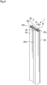
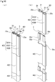
FIG. 1 is a perspective view schematically illustrating a state in which a clearance is sealed by a seal device according to a first embodiment of the present invention. -
FIG. 2 is a perspective view illustrating the seal device according to the first embodiment. -
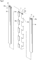
FIG. 3 is an exploded perspective view illustrating the seal device according to the first embodiment. -
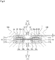
FIG. 4 is an A-A sectional view illustrating the seal device according to the first embodiment inserted into each groove. -
FIG. 5 is an A-A sectional view schematically illustrating the seal device according to the first embodiment when relative displacement of the grooves in the upper-lower direction in the plane of paper occurs. -
FIGS. 6A and 6B are B-B and C-C sectional views schematically illustrating the seal device according to the first embodiment when one groove is deformed in a longitudinal direction. -
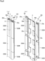
FIGS. 7A and 7B are a perspective view and an exploded perspective view illustrating a seal device according to a second embodiment of the present invention. -
FIGS. 8A and 8B are a perspective view and an exploded perspective view illustrating a seal device according to a third embodiment of the present invention. -
FIGS. 9A and 9B are a perspective view and an exploded perspective view illustrating a seal device according to a fourth embodiment of the present invention. -
FIGS. 10A and 10B are a perspective view and an exploded perspective view illustrating a seal device according to a fifth embodiment of the present invention. -
FIG. 11A is a perspective view illustrating a seal device according to a sixth embodiment of the present invention, andFIG. 11B is a plan sectional view illustrating the seal device according to the sixth embodiment inserted into each groove. -
FIG. 12 is a perspective view illustrating a seal device according to a seventh embodiment of the present invention. -
FIG. 13 is a perspective view illustrating a seal device according to an eighth embodiment of the present invention. - Hereinafter, the modes for implementing a seal device according to the present invention will be described with reference to embodiments.
- A seal device according to a first embodiment will be described with reference to
FIGS. 1 to 6 . In terms of the flow of sealing target fluid, the upper right side in the plane of paper ofFIG. 1 will be hereinafter described as an upstream side U of the seal device, and the lower left side in the plane of paper will be hereinafter described as a downstream side D of the seal device. - The
seal device 1 according to the first embodiment of the present invention is configured to seal, when multiple transition pieces forming part of a housing structure of a combustor unit are arrayed and coupled in an annular shape in a not-shown gas turbine mainly including an air compressor, the combustor unit, and a turbine unit, a clearance G betweentransition pieces - As illustrated in
FIG. 1 , thetransition pieces rectangular paths 55 are each formed at center portions of thetransition pieces path 55 communicates with the inside of a not-shown combustion liner of the combustor unit, and the downstream side D of eachpath 55 communicates with the inside of the not-shown turbine unit. Eachpath 55 guides the sealing target fluid P from the inside of the combustion liner to the inside of the turbine unit (as shown in the direction of a thick black arrow inFIG. 1 ). -
U-shaped grooves 51 continuously formed in an annular shape are each formed at outer peripheral portions of thetransition pieces groove 51 is partitioned by abottom surface 51a andinner surfaces bottom surface 51a (seeFIG. 4 ). Theinner surface 51b described herein is on the downstream side D, and theinner surface 51c described herein is on the upstream side U. Thesegrooves 51 are formed such that the bottom surfaces 51a face each other and are substantially parallel with each other when side end surfaces 52 of thetransition pieces - The
transition pieces seal device 1 is used for preventing outflow of the sealing target fluid P through the clearance G. Hereinafter, theseal device 1 will be described. - As illustrated in
FIGS. 2 to 4 , theseal device 1 includes aseal member 2A inserted into thegroove 51 of thetransition piece 50A (seeFIG. 4 ), aseal member 2B inserted into thegroove 51 of thetransition piece 50B (seeFIG. 4 ), and apartitioning member 3 extending between theseal members FIG. 4 ) and coupled to each of theseal members seal device 1 is disposed between thegrooves 51 across a longitudinal direction of thepartitioning member 3. - The board thickness of the
partitioning member 3 is 1/30 to 1/5 times (more preferably 1/20 to 1/10 times) as great as the dimension of theseal member 2A in a board thickness direction of the partitioning member 3 (i.e., a board thickness direction of a later-describedbase portion 30a of thepartitioning member 3, and such a direction will be hereinafter referred to as a "thickness direction"). With this configuration, the partitioningmember 3 exhibits favorable flexibility. On the other hand, the board thickness of theseal member 2A is 1.2 to 5.0 times (more preferably 1.5 to 3.0 times) as great as the board thickness of thepartitioning member 3. With this configuration, theseal member 2A exhibits favorable durability and higher stiffness than that of the partitioning member. - First, the
seal member 2A will be described with reference toFIGS. 2 to 4 . Note that theseal member 2B has the substantially same configuration as that of theseal member 2A, and therefore, description thereof will be omitted or simplified in description below. Theseal member 2A is an elongated member formed by extrusion molding with nickel-based alloy, linearly continuously extending in a longitudinal direction, and having a C-shape as viewed in the section. Theseal member 2A includes a hollow 20 as a space defined by theseal member 2A, continuously extending in the longitudinal direction, and having an oval shape as viewed in plane, and a slit-shapedopening 21 formed between a pair of opposing side end portions extending along the longitudinal direction of theseal member 2A. The C-shaped section of theseal member 2A is in such a shape that a bottom portion linearly extending substantially in parallel with thebottom surface 51a of thegroove 51, side portions curved in an arc shape at about 90 degrees from upper and lower end portions of the bottom portion to a clearance G side and extending to the clearance G side substantially in parallel with theinner surfaces groove 51, and quadrant circular portions curved in an arc shape at about 90 degrees from end portions of the side portions to face and approach each other are continuous to each other. - Moreover, since the
seal member 2A is the elongated member, theseal member 2A is easily bendable in the longitudinal direction. In addition, since theseal member 2A is formed in the C-shape, the pair of side end portions sandwiching theopening 21 moves close to each other or apart from each other, and therefore, theseal member 2A is easily extendable/contractable as in a spring. - Next, the partitioning
member 3 will be described with reference toFIGS. 2 to 4 . The partitioningmember 3 is formed from a nickel-based alloy thin plate linearly continuously extending in the longitudinal direction. The partitioningmember 3 includes the flat plate-shapedbase portion 30a substantially linearly extending in the longitudinal direction, and projectingelements partitioning member 3 in a transverse direction thereof and having a greater thickness than that of thebase portion 30a. - The dimension of the
base portion 30a of thepartitioning member 3 in the transverse direction is 10 to 100 times (more preferably 20 to 50 times) as great as the board thickness of thepartitioning member 3, and thebase portion 30a is easily elastically deformable in the transverse direction. Moreover, since thebase portion 30a is in the flat plate shape elongated in the longitudinal direction, thebase portion 30a is also easily elastically deformable in the longitudinal direction. - As illustrated in
FIG. 4 , the projectingelement 30b is formed in a dome shape protruding to aninner surface 51b side of thegroove 51, and a dome-shaped space is formed between the projectingelement 30b and thebase portion 30a along the longitudinal direction. The dome shape of theseal member 2A is such a shape that a bisection circular portion curved in an arc shape at about 180 degrees from the end portion of thebase portion 30a to theinner surface 51b side of thegroove 51, side portions linearly extending to the clearance G side substantially in parallel with theinner surface 51b, and quadrant circular portions curved in an arc shape at about 90 degrees from an end portion of the side portion to abase portion 30a side are continuous to each other. Similarly, the projectingelement 30c is formed in a dome shape protruding to aninner surface 51c side of thegroove 51, and communication along the longitudinal direction is allowed between the projectingelement 30c and thebase portion 30a. These projectingelements base portion 30a along the longitudinal direction. - Referring to
FIG. 3 , the multiple projectingelements inner surface 51b side or theinner surface 51c side of thegroove 51. Thus, thebase portion 30a positioned between adjacent ones of the projectingelements 30b in the longitudinal direction can be easily curved to theinner surface 51b side of thegroove 51 in the transverse direction, and thebase portion 30a positioned between adjacent ones of the projectingelements 30c can be easily curved to theinner surface 51c side of thegroove 51 in the transverse direction. Thus, the partitioningmember 3 exhibits excellent flexibility. - Moreover, since the projecting
elements base portion 30a, the partitioningmember 3 is easily arrangeable at a predetermined position with respect to theseal members elements member 3 exhibits excellent flexibility. Further, the projectingelements base portion 30a. - These
seal members partitioning member 3 are made of the same material such as the same nickel-based alloy, and therefore, the amount of deformation due to thermal expansion is substantially equal among theseal members partitioning member 3. Thus, theseal members partitioning member 3 are less susceptible to influence of a deformation difference due to a temperature. - Next, assembly of the
seal device 1 will be described with reference toFIG. 3 . The board thickness of thepartitioning member 3 is shorter than a dimension between the end portions of theseal member 2A sandwiching theopening 21, and the projectingelements partitioning member 3 have a longer dimension in the thickness direction of thepartitioning member 3 than the dimension between the pair of side end portions of theseal member 2A sandwiching theopening 21. Thus, theseal member 2A and thepartitioning member 3 are coupled to each other in such a manner that thebase portion 30a is inserted into theopening 21 and theseal member 2A and thepartitioning member 3 are moved relative to each other in the longitudinal direction while the projectingelements seal member 2B, theseal member 2B and thepartitioning member 3 are coupled to each other as in theseal member 2A. In this manner, assembly of theseal device 1 is completed. - Note that in description below, a position relationship among the
seal members partitioning member 3 as illustrated inFIG. 2 will be described as a "neutral position," and a state at the neutral position will be described as a "neutral position state." - In the neutral position state, a state in which each of the projecting
elements inner surface 20a of the hollow 20 and return stress acts on the projectingelements element 30b or each projectingelement 30c and theinner surface 20a, and a great clearance is formed between thebase portion 30a positioned on the opposite side of each projectingelement 30b or each projectingelement 30c and theinner surface 20a. Thus, the projectingelements seal member 2A. - Next, a state in which the
seal device 1 is inserted into thegrooves 51 of thetransition pieces FIG. 4 . Theseal device 1 inserted into thegrooves 51 is pressed to the downstream side D in response to the pressure of the sealing target fluid P (seeFIG. 1 ), and accordingly, theseal member 2A and theseal member 2B come into contact with theinner surfaces 51b of thegrooves 51. At this point, the partitioningmember 3 is, by the pressure of the sealing target fluid P, specifically slightly bent in a curved shape in the transverse direction such that the center of thebase portion 30a protrudes to the downstream side D, but such a bending amount is small. Thus, thebase portion 30a is illustrated as a linear shape inFIG. 4 . Note that an example where the dimensions of theseal members grooves 51 in the same direction has been described, but theseal members inner surfaces grooves 51. - The partitioning
member 3 extends across theseal members groove 51 into two spaces on the upstream side U and the downstream side D. Moreover, at a coupling portion between each of theseal members partitioning member 3, thebase portion 30a of thepartitioning member 3 is inserted into theopening 21 of each of theseal members elements base portion 30a across the longitudinal direction. This forms a labyrinth structure. With these configurations, the clearance G between thetransition pieces seal device 1 inserted into thegrooves 51. Note that the board thickness of thebase portion 30a may be adjusted such that thebase portion 30a of thepartitioning member 3 bent in the curved shape in the transverse direction by the pressure of the sealing target fluid P contacts the pair of side end portions sandwiching theopening 21 of each of theseal members - Next, the
seal device 1 when relative displacement of thegrooves 51 occurs due to, e.g., vibration upon operation of the gas turbine will be described with reference toFIGS. 4 and5 . When thetransition pieces grooves 51 in the upper-lower direction in the plane of paper occurs, theseal device 1 first tilts by a clearance Δ (seeFIG. 4 ) between each of theseal members inner surface 51c of thegroove 51 in association with displacement. Each of theseal members seal member 2A in the plane of paper comes into contact with theinner surface 51c of thegroove 51, and part of the lower right side of theseal member 2A in the plane of paper comes into contact with theinner surface 51b of thegroove 51. Moreover, part of the upper left side of theseal member 2B in the plane of paper comes into contact with theinner surface 51c of thegroove 51, and part of the lower right side of theseal member 2A in the plane of paper comes into contact with theinner surface 51b of the groove 51 (seeFIG. 5 ). - Since turning of the
seal members base portion 30a starts elastically deforming in the transverse direction when the amount of relative displacement of thegrooves 51 increases from a state in which theseal members inner surfaces 51c of thegrooves 51. Stress generated by such elastic deformation increases, and accordingly, the projectingelements seal members seal members openings 21 become slightly larger, the projectingelements partitioning member 3 are slightly pressed, and thebase portion 30a of thepartitioning member 3 is elastically deformed in the transverse direction. With this configuration, it is less likely to generate strong friction force between theseal members groove 51, and it is less likely to generate great stress on theseal members partitioning member 3 itself. Thus, great deformation/damage of theseal members elements seal device 1 tolerates relative displacement of thegrooves 51 upon occurrence thereof, and therefore, can hold the seal properties. - Meanwhile, such relative displacement of the
grooves 51 is brought under control, and therefore, theseal members partitioning member 3 relatively turn to the neutral position by the substantially same mechanism as that upon occurrence of displacement. Elastic deformation of thebase portion 30a of thepartitioning member 3 in the transverse direction is brought under control, and tilting of theseal device 1 is brought under control in association with displacement reduction. Thus, theseal members partitioning member 3 return to the neutral position state. - Note that depending on the degree of relative displacement of the
grooves 51, theseal device 1 may tolerate displacement merely by tilting in some cases, or may tolerate displacement by elastic deformation of thebase portion 30a of thepartitioning member 3 in the transverse direction in addition to tilting in other cases. Moreover, depending on the materials/board thicknesses of theseal members partitioning member 3, the degree of displacement, and the pressure of the sealing target fluid P, theseal device 1 may tolerate displacement in such a manner that thebase portion 30a of thepartitioning member 3 is elastically deformed in the transverse direction with theseal members inner surfaces 51b of thegrooves 51 as in the neutral position state. Needless to say, operation of theseal device 1 is changeable depending on, e.g., performance and use environment of theseal device 1, and therefore, is not limited to the above-described operation. The same also applies to description below. - Next, the
seal device 1 when one (thetransition piece 50B in this case) of thegrooves 51 is deformed and curved in the longitudinal direction relative to the other one (thetransition piece 50A in this case) of thegrooves 51 due to, e.g., thermal expansion caused by a high temperature of the gas turbine will be described with reference toFIGS. 6A and 6B . Note that description overlapping with description regarding occurrence of relative displacement of thegrooves 51 will be omitted. - As illustrated in
FIG. 6B , theseal member 2B inserted into thegroove 51 of thetransition piece 50B deformed in an arc shape is pressed by the sealing target fluid P (seeFIG. 1 ), and accordingly, is bent in a curved shape in the longitudinal direction in association with such deformation of thegroove 51. The partitioningmember 3 exhibits excellent flexibility in the longitudinal direction as described above, and the projectingelements base portion 30a. Thus, thebase portion 30a of thepartitioning member 3 is elastically deformed in the longitudinal direction in association with bending of theseal member 2B. - Moreover, as illustrated in
FIG. 6A , thebase portion 30a of thepartitioning member 3 is elastically deformed in the longitudinal direction in association with bending of theseal member 2B as described above. Theseal member 2A inserted into thegroove 51 of thenon-deformed transition piece 50A is in the substantially same state as the neutral position state in the present embodiment in which the deformation amount is slight. Note that although not shown in the figure, theseal member 2A is also bent in a curved shape depending on the amount of deformation of theseal member 2B in some cases. - As described above, in the
seal device 1, even when onegroove 51 itself is relatively deformed, the partitioningmember 3 and theseal members groove 51 is absorbed. Further, the state of contact between theinner surface 51b of thegroove 51 and theseal member 2B is easily holdable, and therefore, the seal properties are held. - Note that when relative displacement of the
grooves 51 due to vibration as described above and relative deformation of onegroove 51 itself due to thermal expansion occur in a complex manner, theseal device 1 is operated in a complex manner in response to such a situation, and therefore, tolerates displacement, deformation, etc. occurred in a complex manner. - As described above, when relative displacement of the
grooves 51 due to vibration, deformation of thegroove 51 itself due to thermal expansion, etc. occur, each of theseal members partitioning member 3 move relative to each other, and therefore, theseal device 1 can follow displacement, deformation, etc. Thus, theseal members inner surfaces grooves 51, locally-strong friction force is less generated at theseal members seal members - Moreover, the
seal device 1 is configured such that theseal members member 3. Thus, even when relative displacement of thegrooves 51 or deformation of thegroove 51 itself occurs, direct contact of thepartitioning member 3 with thetransition pieces seal members seal members seal members inner surfaces groove 51, and theseal members transition pieces seal device 1. - Moreover, the partitioning
member 3 is the thin plate exhibiting favorable flexibility, and is also movable relative to theseal members grooves 51, the partitioningmember 3 can follow such displacement and can be elastically deformed. Moreover, occurrence of cracking or rupturing is also prevented. - Further, even when turning or movement of the
seal members grooves 51, relative turning (movement) of theseal members partitioning member 3, and bending/elastic deformation of thebase portion 30a of thepartitioning member 3 in response to relative displacement of thegrooves 51 or deformation of thegrooves 51 themselves do not fully return to the neutral position state after relative displacement of thegrooves 51 or deformation of thegrooves 51 themselves has been brought under control, if thepartitioning member 3 is coupled to theseal members grooves 51, the seal properties can be held. Note that relative movement of theseal members partitioning member 3 includes not only turning as described above, but also relative movement in the longitudinal direction, the transverse direction, and the thickness direction. - Next, a seal device according to a second embodiment of the present invention will be described with reference to
FIGS. 7A and 7B . Note that the same reference numerals are used to represent the same components as those described in the above-described embodiment and overlapping description will be omitted. - The
seal device 101 in the second embodiment will be described. As illustrated inFIGS. 7A and 7B , each ofseal members seal device 101 is, in the present embodiment, configured such thatlinear slits 22 penetrating from the outside of theseal member 102A or theseal member 102B to the hollow 20 and extending in a thickness direction are formed at substantially equal intervals in a longitudinal direction of theseal device 101 at an end portion on anopening 21 side and an end portion facing anopening 21. Thus, flexibility of theseal members grooves 51 is exhibited. - Note that the
slits 22 may be formed at unequal intervals depending on, e.g., the shape of thegroove 51 or the degree of deformation of thegroove 51, and arrangement of theslits 22 may be changeable as necessary. Further, note that theslits 22 may be formed only on theopening 21 side of the seal member or may be formed only at the end portion facing theopening 21, and are not limited to above. - Next, a seal device according to a third embodiment of the present invention will be described with reference to
FIGS. 8A and 8B . Note that the same reference numerals are used to represent the same components as those described in the above-described embodiments and overlapping description will be omitted. - The
seal device 201 in the third embodiment will be described. As illustrated inFIGS. 8A and 8B , in the present embodiment, each ofseal members seal device 201 is substantially equally divided in a longitudinal direction, and themultiple seal members 202A or themultiple seal members 202B are coupled along a longitudinal direction of apartitioning member 3. With this configuration, adjacent ones of theseal members 202A or theseal members 202B in the longitudinal direction relatively tilt at coupling portions thereof, and therefore, flexibility of the coupledseal members 202A and the coupledseal members 202B in the longitudinal direction is enhanced. Consequently, the degree of freedom in relative movement of the coupledseal members 202A and the coupledseal members 202B is high. - Moreover, as compared to a case where the
seal members partitioning member 3, the multiple dividedseal members - Note that depending on, e.g., the shape of a
groove 51 or the degree of deformation of thegroove 51, themultiple seal members partitioning member 3. - Next, a seal device according to a fourth embodiment of the present invention will be described with reference to
FIGS. 9A and 9B . Note that the same reference numerals are used to represent the same components as those described in the above-described embodiments and overlapping description will be omitted. - The
seal device 301 in the fourth embodiment will be described. As illustrated inFIGS. 9A and 9B , in the present embodiment,seal members seal device 301 are divided at substantially equal intervals in a longitudinal direction. At eachseal member seal members cutout portion 23 recessed in the longitudinal direction and penetrating in a thickness direction is formed at one end portion on aninner surface 51c (seeFIG. 4 ) side of agroove 51. Moreover, at each projectingelement 130c of apartitioning member 103, aplate spring portion 31 cut and raised in a rectangular shape to protrude a side (i.e., theinner surface 51c side of the groove 51) apart from abase portion 30a and shaped in a plate spring shape is formed. Theseplate spring portions 31 are arranged at substantially equal intervals in a longitudinal direction of thepartitioning member 103, and have spring properties in a normal direction (i.e., the thickness direction) of thebase portion 30a. - In the
seal device 301, when theseal members partitioning member 103 are coupled to each other, theplate spring portions 31 protrude to the outside (i.e., a side of theinner surface 51c of the groove 51) of theseal member 302A or theseal member 302B through thecutout portions 23. Thus, when theseal device 301 is inserted into thegrooves 51, a state in which eachplate spring portion 31 contacts aninner surface 51c of thegroove 51 and return stress acts on eachplate spring portion 31 is brought, and theseal members inner surfaces 51b (seeFIG. 4 ) of thegrooves 51. Consequently, seal properties can be improved. In addition, movement of theseal device 301 itself relative to thegrooves 51 in the longitudinal direction, a transverse direction, and the thickness direction is reduced, and therefore, rattling of theseal device 301 in thegrooves 51 can be reduced. - Note that the
cutout portions 23 and theplate spring portions 31 may be formed only on aseal member 302A side or aseal member 302B side, and are not limited to above. Similarly, theplate spring portions 31 may be arranged at unequal intervals. Accordingly, the dimension of the seal member in the longitudinal direction may be adjusted according to arrangement of theplate spring portions 31. Moreover, theplate spring portions 31 may protrude outwardly through through-holes formed to penetrate from the outside of the seal member to an inner space, and thecutout portions 23 are not limited to above. - Next, a seal device according to a fifth embodiment of the present invention will be described with reference to
FIGS. 10A and 10B . Note that the same reference numerals are used to represent the same components as those described in the above-described embodiments and overlapping description will be omitted. - The
seal device 401 in the fifth embodiment will be described. As illustrated inFIGS. 10A and 10B , in the present embodiment, eachseal body member 402 of theseal device 401 is configured such thatseal members coupling portion 402C. With this configuration, a coupling process is facilitated as compared to a case where the multiple dividedseal members partitioning member 3. - Moreover, the
seal body member 402 is configured such that theseal members coupling portion 402C, and therefore, exhibits excellent seal properties. - Next, a seal device according to a sixth embodiment of the present invention will be described with reference to
FIGS. 11A and 11B . Note that the same reference numerals are used to represent the same components as those described in the above-described embodiments and overlapping description will be omitted. - The
seal device 501 in the sixth embodiment will be described. As illustrated inFIG. 11A , in the present embodiment, apartitioning member 203 of theseal device 501 is bent in a curved shape such that a substantially center portion of abase portion 230a in a transverse direction protrudes to a projectingelement 30b side. Both end portions of thepartitioning member 203 in the transverse direction are movable close to each other or apart from each other, and therefore, the partitioningmember 203 is easily extendable/contractable as in a spring. - As illustrated in
FIG. 11B , theseal device 501 inserted intogrooves 51 is in such a state that theseal device 501 is bent in a curved shape such that thebase portion 230a protrudes to the projectingelement 30b side. By action of return force generated by separation of both end portions in the transverse direction and extension of thebase portion 230a and deformation force for pressing, in a protruding direction, the substantially center portion of thebase portion 230a in the transverse direction by the pressure of sealing target fluid P (seeFIG. 1 ) to elastically deform thebase portion 230a such that both end portions in the transverse direction move close to each other, part of the upper left side of aseal member 2A in the plane of paper is pressed by aninner surface 51c of thegroove 51, and part of the lower right side of theseal member 2A in the plane of paper is pressed by aninner surface 51b of thegroove 51. Moreover, part of the upper right side of aseal member 2B in the plane of paper is pressed by aninner surface 51c of thegroove 51, and part of the lower left side of theseal member 2B in the plane of paper is pressed by aninner surface 51b of thegroove 51. Thus, theseal members inner surfaces grooves 51, and therefore, seal properties can be improved. Moreover, movement of theseal device 501 itself relative to thegrooves 51 in a longitudinal direction, the transverse direction, and a thickness direction is reduced, and therefore, rattling of theseal device 501 in thegrooves 51 can be reduced. - Next, a seal device according to a seventh embodiment of the present invention will be described with reference to
FIG. 12 . Note that the same reference numerals are used to represent the same components as those described in the above-described embodiments and overlapping description will be omitted. - The
seal device 601 in the seventh embodiment will be described. As illustrated inFIG. 12 , in the present embodiment, a folded-back portion 32b protruding outwardly from an end portion of aseal member 2A or aseal member 2B in a longitudinal direction thereof and folded back to aninner surface 51b side of agroove 51 and a folded-back portion 32c similarly folded back to aninner surface 51c side of thegroove 51 are formed at each end portion of apartitioning member 303 of theseal device 601 in a longitudinal direction thereof. The folded-backportions seal members seal members partitioning member 303 in the longitudinal direction is restricted. - Note that a form in which the folded-back portions are separated from the partitioning member and are welded and fixed to the partitioning member after the partitioning member and the seal members have been coupled to each other may be employed other than the folded-back
portions - Next, a seal device according to an eighth embodiment of the present invention will be described with reference to
FIG. 13 . Note that the same reference numerals are used to represent the same components as those described in the above-described embodiments and overlapping description will be omitted. - The
seal device 701 in the eighth embodiment will be described. As illustrated inFIG. 13 , in the present embodiment, at one end portion of apartitioning member 403 of theseal device 701 in a longitudinal direction thereof, an accordion-shapedplate spring portion 33 is formed in such a manner that a center portion of such an end portion is cut and raised in a rectangular shape and is shaped in an accordion shape. The accordion-shapedplate spring portion 33 protrudes from end portions of aseal member 202A and aseal member 202B in a longitudinal direction thereof, and contacts the end portions of theseal members partitioning member 403 in the longitudinal direction thereof, folded-backportions FIG. 12 ). - With this configuration, movement of the coupled
seal members 202A and the coupledseal members 202B relative to thepartitioning member 403 in the longitudinal direction can be restricted, and theseal members 202A and theseal members 202B are pressed toward the folded-backportions partitioning member 403 by the accordion-shapedplate spring portion 33. Thus, a non-contact state of adjacent ones of theseal members 202A or adjacent ones of theseal members 202B can be prevented, and therefore, seal properties can be reliably held. - Note that other than the accordion-shaped
plate spring portion 33, a coil spring or a bellows may be welded and fixed to protrude toward the end portion of the seal member, and the present invention is not limited to the accordion-shapedplate spring portion 33. Further, note that a form in which the accordion-shaped plate spring portion is separated from the partitioning member and is welded and fixed to the partitioning member after the partitioning member and the seal members have been coupled to each other may be employed. - The embodiments of the present invention have been described above with reference to the drawings, but specific configurations are not limited to these embodiments. Changes and additions made without departing from the scope of the present invention are included in the present invention.
- For example, the
slits 22 of the second embodiment may be applied to each of the divided seal members of the third to fifth embodiments. Thecutout portions 23 and theplate spring portions 31 of the fourth embodiment may be applied to the seal members and the partitioning member of the first, fifth, and sixth embodiments. As in thecoupling portion 402C of the fifth embodiment, the pair of seal members formed continuously in the longitudinal direction in the first and second embodiments may be configured as an integrated seal body member by means of a coupling portion. Each of the divided seal members of the third to fifth embodiments may be coupled to thepartitioning member 203 of the sixth embodiment. The folded-backportions plate spring portion 33 of the seventh and eighth embodiments may be applied to the first to sixth embodiments. The configurations of the first to eighth embodiments may be combined as necessary depending on the intended use. - Moreover, the first to eighth embodiments have been described that the seal device is in the form used for sealing a portion between the
transition pieces - Each seal member and the partitioning member are not limited to nickel-based alloy as long as these components are made of alloy containing nickel, such as nickel superalloy or stainless steel. On the other hand, these components may be made of ceramic or metal containing no nickel depending on the intended use.
- Moreover, each seal member and the partitioning member have been described as the form in which these components are coupled with the
base portion 30a being inserted into theopenings 21 and the projectingelements hollows 20, but the present invention is not limited to above. Each seal member may be coupled in such a hinge shape that each seal member is turnable and pivotable relative to the partitioning member. - The projecting elements of the partitioning member have been described as the form in which the hollow dome-shaped projecting elements are alternately formed on the front and back sides of the
base portion 30a across the longitudinal direction, but the shape thereof is not limited to above. The projecting element may be formed in, e.g., a solid dome shape, the shape of a hollow rectangular tubular body, the shape of a multilayer plate contacting the base portion, or a cylindrical shape protruding in the transverse direction of the base portion. - Moreover, regarding arrangement of the projecting elements of the partitioning member, adjacent ones of the alternately-formed projecting elements may be apart from each other in the longitudinal direction, or the projecting elements may be arranged on the
inner surface 51b side or theinner surface 51c side of thegroove 51 or may be continuously formed across the longitudinal direction so as to form one continuous projecting portion at each end of the partitioning member. The present invention is not limited to above. - Further, each projecting element of the partitioning member has been described as the form in which each projecting element is formed in such a manner that both end portions of the
partitioning member 3 in the transverse direction are folded back, but the present invention is not limited to above. As long as the seal members and partitioning member can be integrally formed, a form in which each projecting element formed separately from the base portion is fixed by, e.g., welding may be employed. -
- 1
- Seal device
- 2A, 2B
- Seal member (First and Second seal members)
- 3
- Partitioning member
- 20
- Hollow
- 21
- Opening
- 30a
- Base portion
- 30b, 30c
- Projecting element (Projecting portion)
- 50A, 50B
- Transition piece (First and Second components)
- 51
- Groove
- 101 to 701
- Seal device
- 102A to 402A
- Seal member (First or Second seal member)
- 102B to 402B
- Seal member (Second or First seal member)
- 103 to 403
- Partitioning member
- 130c
- Projecting element (Projecting portion)
- 203
- Partitioning member
- 230a
- Base portion
Claims (8)
- A seal device inserted into and disposed between grooves each formed at each of first and second components which are adjacent to each other and collectively form a housing structure, comprising:a first seal member inserted into the groove of the first component;a second seal member inserted into the groove of the second component; anda partitioning member extending between the first and second seal members to partition a space between the grooves of the first and second components and arranged movably relative to the first and second seal members.
- The seal device according to claim 1, wherein the partitioning member is formed from a thin plate.
- The seal device according to claim 1 or 2, wherein the partitioning member includes a base portion formed in a flat plate shape and projecting portions formed at both ends of the base portion in a transverse direction thereof and extending in a longitudinal direction of the partitioning member and having a greater thickness than that of the base portion, and
each of the first and second seal members is provided with a hollow in which the projecting portions are housed and an opening which is formed with a shorter dimension in a thickness direction than a dimension of each projecting portion in the thickness direction and into which the base portion is inserted. - The seal device according to claim 3, wherein the projecting portions are formed in such a manner that both end portions of the partitioning member in a transverse direction thereof are folded back.
- The seal device according to claim 3 or 4, wherein each of the projecting portions is divided into multiple projecting elements scattered in the longitudinal direction.
- The seal device according to any one of claim 5, wherein the projecting elements are sorted into a first group in which the projecting elements are formed by folding back the end portions of the partitioning member to a front side of the base portion and a second group in which the projecting elements are formed by folding back the end portions of the partitioning member to a back side of the base portion.
- The seal device according to any one of claims 1 to 6, wherein each of the first and second seal members is divided into plural parts aligned in the longitudinal direction thereof.
- The seal device according to any one of claims 1 to 7, wherein the first and second seal members and the partitioning member are made of identical alloy containing nickel.
Priority Applications (1)
| Application Number | Priority Date | Filing Date | Title |
|---|---|---|---|
| EP25182125.2A EP4596838A3 (en) | 2018-05-21 | 2019-05-17 | Seal device |
Applications Claiming Priority (2)
| Application Number | Priority Date | Filing Date | Title |
|---|---|---|---|
| JP2018097253 | 2018-05-21 | ||
| PCT/JP2019/019617 WO2019225490A1 (en) | 2018-05-21 | 2019-05-17 | Seal device |
Related Child Applications (2)
| Application Number | Title | Priority Date | Filing Date |
|---|---|---|---|
| EP25182125.2A Division-Into EP4596838A3 (en) | 2018-05-21 | 2019-05-17 | Seal device |
| EP25182125.2A Division EP4596838A3 (en) | 2018-05-21 | 2019-05-17 | Seal device |
Publications (3)
| Publication Number | Publication Date |
|---|---|
| EP3798484A1 true EP3798484A1 (en) | 2021-03-31 |
| EP3798484A4 EP3798484A4 (en) | 2022-03-23 |
| EP3798484B1 EP3798484B1 (en) | 2025-08-13 |
Family
ID=68615746
Family Applications (2)
| Application Number | Title | Priority Date | Filing Date |
|---|---|---|---|
| EP19807451.0A Active EP3798484B1 (en) | 2018-05-21 | 2019-05-17 | Seal device |
| EP25182125.2A Pending EP4596838A3 (en) | 2018-05-21 | 2019-05-17 | Seal device |
Family Applications After (1)
| Application Number | Title | Priority Date | Filing Date |
|---|---|---|---|
| EP25182125.2A Pending EP4596838A3 (en) | 2018-05-21 | 2019-05-17 | Seal device |
Country Status (6)
| Country | Link |
|---|---|
| US (1) | US11536150B2 (en) |
| EP (2) | EP3798484B1 (en) |
| JP (1) | JP7224739B2 (en) |
| KR (1) | KR102475240B1 (en) |
| CN (1) | CN112020620B (en) |
| WO (1) | WO2019225490A1 (en) |
Families Citing this family (4)
| Publication number | Priority date | Publication date | Assignee | Title |
|---|---|---|---|---|
| US11187095B1 (en) * | 2020-12-29 | 2021-11-30 | General Electric Company | Magnetic aft frame side seals |
| EP4074941A1 (en) * | 2021-04-13 | 2022-10-19 | Siemens Energy Global GmbH & Co. KG | Sealing strip element and sealing arrangement comprising said sealing strip element |
| EP4388179A1 (en) * | 2021-08-19 | 2024-06-26 | Siemens Energy Global GmbH & Co. KG | Sealing device with displaceable abutment |
| GB202406713D0 (en) * | 2024-05-13 | 2024-06-26 | Rolls Royce Plc | A seal, a seal assembly and a method |
Family Cites Families (22)
| Publication number | Priority date | Publication date | Assignee | Title |
|---|---|---|---|---|
| BE481135A (en) | 1947-03-11 | |||
| DE3742557A1 (en) * | 1987-12-16 | 1989-06-29 | Sueddeutsche Kuehler Behr | Connecting profile for connecting the borders of two housing parts |
| US5104286A (en) * | 1991-02-08 | 1992-04-14 | Westinghouse Electric Corp. | Recirculation seal for a gas turbine exhaust diffuser |
| JP2002201913A (en) * | 2001-01-09 | 2002-07-19 | Mitsubishi Heavy Ind Ltd | Split wall of gas turbine and shroud |
| GB0228748D0 (en) * | 2002-12-10 | 2003-01-15 | Alstom Switzerland Ltd | Sealing arrangement |
| JP2005016324A (en) | 2003-06-23 | 2005-01-20 | Hitachi Ltd | Seal device and gas turbine |
| JP4201190B2 (en) * | 2003-10-30 | 2008-12-24 | ダイハツ工業株式会社 | Automotive door seal structure |
| JP4715114B2 (en) * | 2004-06-17 | 2011-07-06 | トヨタ自動車株式会社 | Battery case lid packing, battery case lid manufacturing method, battery manufacturing method |
| US7788932B2 (en) * | 2005-08-23 | 2010-09-07 | Mitsubishi Heavy Industries, Ltd. | Seal structure for gas turbine combustor |
| US7845649B2 (en) * | 2005-09-30 | 2010-12-07 | General Electric Company | Methods and apparatus to facilitate sealing high pressure joints |
| JP4690905B2 (en) * | 2006-02-17 | 2011-06-01 | 三菱重工業株式会社 | SEALING DEVICE AND GAS TURBINE HAVING THE SAME |
| US9004495B2 (en) | 2008-09-15 | 2015-04-14 | Stein Seal Company | Segmented intershaft seal assembly |
| US8398090B2 (en) * | 2010-06-09 | 2013-03-19 | General Electric Company | Spring loaded seal assembly for turbines |
| DE102010050519A1 (en) * | 2010-11-08 | 2012-05-10 | Nft Nanofiltertechnik Gmbh | heat exchangers |
| DE202011103439U1 (en) * | 2011-07-20 | 2012-07-23 | Reinz-Dichtungs-Gmbh | sealing system |
| EP2867480B8 (en) * | 2012-06-18 | 2017-07-12 | Ansaldo Energia IP UK Limited | Seal between static turbine parts |
| EP2964899B1 (en) * | 2013-03-05 | 2018-12-05 | Rolls-Royce Corporation | Structure and method for providing compliance and sealing between ceramic and metallic structures |
| DE102013205922B4 (en) | 2013-04-04 | 2016-09-29 | MTU Aero Engines AG | Apparatus and method for fastening sealing elements |
| US10240473B2 (en) * | 2013-08-30 | 2019-03-26 | United Technologies Corporation | Bifurcated sliding seal |
| FR3021692B1 (en) * | 2014-05-27 | 2016-05-13 | Snecma | SEAL PLATE WITH FUSE FUNCTION |
| CN206754357U (en) * | 2017-04-27 | 2017-12-15 | 北京新能源汽车股份有限公司 | Connector and connector assembly with same |
| CN107956770A (en) * | 2017-08-14 | 2018-04-24 | 东莞市众金家具有限公司 | New wooden laminate fast push-pull connection method |
-
2019
- 2019-05-17 JP JP2020521200A patent/JP7224739B2/en active Active
- 2019-05-17 KR KR1020207032806A patent/KR102475240B1/en active Active
- 2019-05-17 EP EP19807451.0A patent/EP3798484B1/en active Active
- 2019-05-17 EP EP25182125.2A patent/EP4596838A3/en active Pending
- 2019-05-17 US US17/050,420 patent/US11536150B2/en active Active
- 2019-05-17 WO PCT/JP2019/019617 patent/WO2019225490A1/en not_active Ceased
- 2019-05-17 CN CN201980027758.5A patent/CN112020620B/en active Active
Also Published As
| Publication number | Publication date |
|---|---|
| JPWO2019225490A1 (en) | 2021-06-17 |
| CN112020620B (en) | 2022-08-09 |
| US11536150B2 (en) | 2022-12-27 |
| EP3798484B1 (en) | 2025-08-13 |
| EP3798484A4 (en) | 2022-03-23 |
| US20210189896A1 (en) | 2021-06-24 |
| WO2019225490A1 (en) | 2019-11-28 |
| CN112020620A (en) | 2020-12-01 |
| EP4596838A3 (en) | 2025-11-12 |
| EP4596838A2 (en) | 2025-08-06 |
| KR102475240B1 (en) | 2022-12-07 |
| JP7224739B2 (en) | 2023-02-20 |
| KR20200139820A (en) | 2020-12-14 |
Similar Documents
| Publication | Publication Date | Title |
|---|---|---|
| EP3798484B1 (en) | Seal device | |
| US6764078B2 (en) | Brush seal device | |
| US6648334B2 (en) | Brush seal device | |
| JP4577813B2 (en) | Sealing device | |
| JP4322600B2 (en) | Sealing device | |
| EP1873426B1 (en) | A seal assembly | |
| EP1566521B1 (en) | Seal device | |
| US8950751B2 (en) | Compliant element | |
| US8814173B2 (en) | Seal and seal arrangement for confining leakage flows between adjacent components of turbo-machines and gas turbines | |
| US7246995B2 (en) | Seal usable between a transition and a turbine vane assembly in a turbine engine | |
| US20080073861A1 (en) | Seal device | |
| US9188228B2 (en) | Layered seal for turbomachinery | |
| EP1365181A2 (en) | Sheet brush seal | |
| US10047622B2 (en) | Flexible layered seal for turbomachinery | |
| CN102278147A (en) | Spring loaded seal assembly for turbines | |
| CN112780419B (en) | Gas turbine engine seals | |
| JP7391675B2 (en) | sealing device | |
| JP7808289B2 (en) | Seal Structure | |
| JP3986518B2 (en) | Shaft seal mechanism | |
| JP2019206984A (en) | Seal mechanism | |
| JP2026022818A (en) | Gaskets and Sealing Structures | |
| WO2026047428A1 (en) | Seal assembly |
Legal Events
| Date | Code | Title | Description |
|---|---|---|---|
| STAA | Information on the status of an ep patent application or granted ep patent |
Free format text: STATUS: THE INTERNATIONAL PUBLICATION HAS BEEN MADE |
|
| PUAI | Public reference made under article 153(3) epc to a published international application that has entered the european phase |
Free format text: ORIGINAL CODE: 0009012 |
|
| STAA | Information on the status of an ep patent application or granted ep patent |
Free format text: STATUS: REQUEST FOR EXAMINATION WAS MADE |
|
| 17P | Request for examination filed |
Effective date: 20201201 |
|
| AK | Designated contracting states |
Kind code of ref document: A1 Designated state(s): AL AT BE BG CH CY CZ DE DK EE ES FI FR GB GR HR HU IE IS IT LI LT LU LV MC MK MT NL NO PL PT RO RS SE SI SK SM TR |
|
| AX | Request for extension of the european patent |
Extension state: BA ME |
|
| DAV | Request for validation of the european patent (deleted) | ||
| DAX | Request for extension of the european patent (deleted) | ||
| A4 | Supplementary search report drawn up and despatched |
Effective date: 20220223 |
|
| RIC1 | Information provided on ipc code assigned before grant |
Ipc: F01D 9/02 20060101ALI20220217BHEP Ipc: F02C 7/28 20060101ALI20220217BHEP Ipc: F01D 11/00 20060101ALI20220217BHEP Ipc: F16J 15/08 20060101AFI20220217BHEP |
|
| STAA | Information on the status of an ep patent application or granted ep patent |
Free format text: STATUS: EXAMINATION IS IN PROGRESS |
|
| 17Q | First examination report despatched |
Effective date: 20230919 |
|
| GRAP | Despatch of communication of intention to grant a patent |
Free format text: ORIGINAL CODE: EPIDOSNIGR1 |
|
| STAA | Information on the status of an ep patent application or granted ep patent |
Free format text: STATUS: GRANT OF PATENT IS INTENDED |
|
| INTG | Intention to grant announced |
Effective date: 20250409 |
|
| GRAS | Grant fee paid |
Free format text: ORIGINAL CODE: EPIDOSNIGR3 |
|
| GRAA | (expected) grant |
Free format text: ORIGINAL CODE: 0009210 |
|
| STAA | Information on the status of an ep patent application or granted ep patent |
Free format text: STATUS: THE PATENT HAS BEEN GRANTED |
|
| AK | Designated contracting states |
Kind code of ref document: B1 Designated state(s): AL AT BE BG CH CY CZ DE DK EE ES FI FR GB GR HR HU IE IS IT LI LT LU LV MC MK MT NL NO PL PT RO RS SE SI SK SM TR |
|
| REG | Reference to a national code |
Ref country code: GB Ref legal event code: FG4D |
|
| REG | Reference to a national code |
Ref country code: CH Ref legal event code: EP |
|
| REG | Reference to a national code |
Ref country code: DE Ref legal event code: R096 Ref document number: 602019074130 Country of ref document: DE |
|
| REG | Reference to a national code |
Ref country code: IE Ref legal event code: FG4D |
|
| REG | Reference to a national code |
Ref country code: NL Ref legal event code: MP Effective date: 20250813 |
|
| PG25 | Lapsed in a contracting state [announced via postgrant information from national office to epo] |
Ref country code: IS Free format text: LAPSE BECAUSE OF FAILURE TO SUBMIT A TRANSLATION OF THE DESCRIPTION OR TO PAY THE FEE WITHIN THE PRESCRIBED TIME-LIMIT Effective date: 20251213 |
|
| PG25 | Lapsed in a contracting state [announced via postgrant information from national office to epo] |
Ref country code: NO Free format text: LAPSE BECAUSE OF FAILURE TO SUBMIT A TRANSLATION OF THE DESCRIPTION OR TO PAY THE FEE WITHIN THE PRESCRIBED TIME-LIMIT Effective date: 20251113 |
|
| REG | Reference to a national code |
Ref country code: LT Ref legal event code: MG9D |
|
| PG25 | Lapsed in a contracting state [announced via postgrant information from national office to epo] |
Ref country code: PT Free format text: LAPSE BECAUSE OF FAILURE TO SUBMIT A TRANSLATION OF THE DESCRIPTION OR TO PAY THE FEE WITHIN THE PRESCRIBED TIME-LIMIT Effective date: 20251215 |
|
| PG25 | Lapsed in a contracting state [announced via postgrant information from national office to epo] |
Ref country code: FI Free format text: LAPSE BECAUSE OF FAILURE TO SUBMIT A TRANSLATION OF THE DESCRIPTION OR TO PAY THE FEE WITHIN THE PRESCRIBED TIME-LIMIT Effective date: 20250813 |
|
| PG25 | Lapsed in a contracting state [announced via postgrant information from national office to epo] |
Ref country code: NL Free format text: LAPSE BECAUSE OF FAILURE TO SUBMIT A TRANSLATION OF THE DESCRIPTION OR TO PAY THE FEE WITHIN THE PRESCRIBED TIME-LIMIT Effective date: 20250813 Ref country code: HR Free format text: LAPSE BECAUSE OF FAILURE TO SUBMIT A TRANSLATION OF THE DESCRIPTION OR TO PAY THE FEE WITHIN THE PRESCRIBED TIME-LIMIT Effective date: 20250813 |
|
| PG25 | Lapsed in a contracting state [announced via postgrant information from national office to epo] |
Ref country code: GR Free format text: LAPSE BECAUSE OF FAILURE TO SUBMIT A TRANSLATION OF THE DESCRIPTION OR TO PAY THE FEE WITHIN THE PRESCRIBED TIME-LIMIT Effective date: 20251114 |
|
| PG25 | Lapsed in a contracting state [announced via postgrant information from national office to epo] |
Ref country code: SE Free format text: LAPSE BECAUSE OF FAILURE TO SUBMIT A TRANSLATION OF THE DESCRIPTION OR TO PAY THE FEE WITHIN THE PRESCRIBED TIME-LIMIT Effective date: 20250813 |
|
| PG25 | Lapsed in a contracting state [announced via postgrant information from national office to epo] |
Ref country code: LV Free format text: LAPSE BECAUSE OF FAILURE TO SUBMIT A TRANSLATION OF THE DESCRIPTION OR TO PAY THE FEE WITHIN THE PRESCRIBED TIME-LIMIT Effective date: 20250813 |
|
| PG25 | Lapsed in a contracting state [announced via postgrant information from national office to epo] |
Ref country code: PL Free format text: LAPSE BECAUSE OF FAILURE TO SUBMIT A TRANSLATION OF THE DESCRIPTION OR TO PAY THE FEE WITHIN THE PRESCRIBED TIME-LIMIT Effective date: 20250813 Ref country code: BG Free format text: LAPSE BECAUSE OF FAILURE TO SUBMIT A TRANSLATION OF THE DESCRIPTION OR TO PAY THE FEE WITHIN THE PRESCRIBED TIME-LIMIT Effective date: 20250813 |
|
| PG25 | Lapsed in a contracting state [announced via postgrant information from national office to epo] |
Ref country code: RS Free format text: LAPSE BECAUSE OF FAILURE TO SUBMIT A TRANSLATION OF THE DESCRIPTION OR TO PAY THE FEE WITHIN THE PRESCRIBED TIME-LIMIT Effective date: 20251113 |
|
| PG25 | Lapsed in a contracting state [announced via postgrant information from national office to epo] |
Ref country code: ES Free format text: LAPSE BECAUSE OF FAILURE TO SUBMIT A TRANSLATION OF THE DESCRIPTION OR TO PAY THE FEE WITHIN THE PRESCRIBED TIME-LIMIT Effective date: 20250813 |
|
| REG | Reference to a national code |
Ref country code: AT Ref legal event code: MK05 Ref document number: 1824953 Country of ref document: AT Kind code of ref document: T Effective date: 20250813 |
|
| PG25 | Lapsed in a contracting state [announced via postgrant information from national office to epo] |
Ref country code: SM Free format text: LAPSE BECAUSE OF FAILURE TO SUBMIT A TRANSLATION OF THE DESCRIPTION OR TO PAY THE FEE WITHIN THE PRESCRIBED TIME-LIMIT Effective date: 20250813 |
|
| PG25 | Lapsed in a contracting state [announced via postgrant information from national office to epo] |
Ref country code: DK Free format text: LAPSE BECAUSE OF FAILURE TO SUBMIT A TRANSLATION OF THE DESCRIPTION OR TO PAY THE FEE WITHIN THE PRESCRIBED TIME-LIMIT Effective date: 20250813 |
|
| PG25 | Lapsed in a contracting state [announced via postgrant information from national office to epo] |
Ref country code: AT Free format text: LAPSE BECAUSE OF FAILURE TO SUBMIT A TRANSLATION OF THE DESCRIPTION OR TO PAY THE FEE WITHIN THE PRESCRIBED TIME-LIMIT Effective date: 20250813 |
|
| PG25 | Lapsed in a contracting state [announced via postgrant information from national office to epo] |
Ref country code: IT Free format text: LAPSE BECAUSE OF FAILURE TO SUBMIT A TRANSLATION OF THE DESCRIPTION OR TO PAY THE FEE WITHIN THE PRESCRIBED TIME-LIMIT Effective date: 20250813 |
|
| PG25 | Lapsed in a contracting state [announced via postgrant information from national office to epo] |
Ref country code: CZ Free format text: LAPSE BECAUSE OF FAILURE TO SUBMIT A TRANSLATION OF THE DESCRIPTION OR TO PAY THE FEE WITHIN THE PRESCRIBED TIME-LIMIT Effective date: 20250813 |
|
| PG25 | Lapsed in a contracting state [announced via postgrant information from national office to epo] |
Ref country code: SK Free format text: LAPSE BECAUSE OF FAILURE TO SUBMIT A TRANSLATION OF THE DESCRIPTION OR TO PAY THE FEE WITHIN THE PRESCRIBED TIME-LIMIT Effective date: 20250813 Ref country code: EE Free format text: LAPSE BECAUSE OF FAILURE TO SUBMIT A TRANSLATION OF THE DESCRIPTION OR TO PAY THE FEE WITHIN THE PRESCRIBED TIME-LIMIT Effective date: 20250813 |