EP3798436A1 - Method and device for determining combustion noise parameters - Google Patents
Method and device for determining combustion noise parameters Download PDFInfo
- Publication number
- EP3798436A1 EP3798436A1 EP20174770.6A EP20174770A EP3798436A1 EP 3798436 A1 EP3798436 A1 EP 3798436A1 EP 20174770 A EP20174770 A EP 20174770A EP 3798436 A1 EP3798436 A1 EP 3798436A1
- Authority
- EP
- European Patent Office
- Prior art keywords
- sequence
- cylinder
- parameter
- rise rate
- surface cylinder
- Prior art date
- Legal status (The legal status is an assumption and is not a legal conclusion. Google has not performed a legal analysis and makes no representation as to the accuracy of the status listed.)
- Granted
Links
Images




Classifications
-
- F—MECHANICAL ENGINEERING; LIGHTING; HEATING; WEAPONS; BLASTING
- F02—COMBUSTION ENGINES; HOT-GAS OR COMBUSTION-PRODUCT ENGINE PLANTS
- F02B—INTERNAL-COMBUSTION PISTON ENGINES; COMBUSTION ENGINES IN GENERAL
- F02B77/00—Component parts, details or accessories, not otherwise provided for
- F02B77/08—Safety, indicating, or supervising devices
-
- F—MECHANICAL ENGINEERING; LIGHTING; HEATING; WEAPONS; BLASTING
- F02—COMBUSTION ENGINES; HOT-GAS OR COMBUSTION-PRODUCT ENGINE PLANTS
- F02D—CONTROLLING COMBUSTION ENGINES
- F02D35/00—Controlling engines, dependent on conditions exterior or interior to engines, not otherwise provided for
- F02D35/02—Controlling engines, dependent on conditions exterior or interior to engines, not otherwise provided for on interior conditions
- F02D35/027—Controlling engines, dependent on conditions exterior or interior to engines, not otherwise provided for on interior conditions using knock sensors
-
- F—MECHANICAL ENGINEERING; LIGHTING; HEATING; WEAPONS; BLASTING
- F02—COMBUSTION ENGINES; HOT-GAS OR COMBUSTION-PRODUCT ENGINE PLANTS
- F02D—CONTROLLING COMBUSTION ENGINES
- F02D35/00—Controlling engines, dependent on conditions exterior or interior to engines, not otherwise provided for
- F02D35/02—Controlling engines, dependent on conditions exterior or interior to engines, not otherwise provided for on interior conditions
- F02D35/023—Controlling engines, dependent on conditions exterior or interior to engines, not otherwise provided for on interior conditions by determining the cylinder pressure
-
- F—MECHANICAL ENGINEERING; LIGHTING; HEATING; WEAPONS; BLASTING
- F02—COMBUSTION ENGINES; HOT-GAS OR COMBUSTION-PRODUCT ENGINE PLANTS
- F02D—CONTROLLING COMBUSTION ENGINES
- F02D41/00—Electrical control of supply of combustible mixture or its constituents
- F02D41/009—Electrical control of supply of combustible mixture or its constituents using means for generating position or synchronisation signals
-
- G—PHYSICS
- G01—MEASURING; TESTING
- G01M—TESTING STATIC OR DYNAMIC BALANCE OF MACHINES OR STRUCTURES; TESTING OF STRUCTURES OR APPARATUS, NOT OTHERWISE PROVIDED FOR
- G01M15/00—Testing of engines
- G01M15/04—Testing internal-combustion engines
- G01M15/08—Testing internal-combustion engines by monitoring pressure in cylinders
-
- F—MECHANICAL ENGINEERING; LIGHTING; HEATING; WEAPONS; BLASTING
- F02—COMBUSTION ENGINES; HOT-GAS OR COMBUSTION-PRODUCT ENGINE PLANTS
- F02D—CONTROLLING COMBUSTION ENGINES
- F02D2200/00—Input parameters for engine control
- F02D2200/02—Input parameters for engine control the parameters being related to the engine
- F02D2200/025—Engine noise, e.g. determined by using an acoustic sensor
-
- F—MECHANICAL ENGINEERING; LIGHTING; HEATING; WEAPONS; BLASTING
- F02—COMBUSTION ENGINES; HOT-GAS OR COMBUSTION-PRODUCT ENGINE PLANTS
- F02D—CONTROLLING COMBUSTION ENGINES
- F02D2250/00—Engine control related to specific problems or objectives
- F02D2250/14—Timing of measurement, e.g. synchronisation of measurements to the engine cycle
-
- Y—GENERAL TAGGING OF NEW TECHNOLOGICAL DEVELOPMENTS; GENERAL TAGGING OF CROSS-SECTIONAL TECHNOLOGIES SPANNING OVER SEVERAL SECTIONS OF THE IPC; TECHNICAL SUBJECTS COVERED BY FORMER USPC CROSS-REFERENCE ART COLLECTIONS [XRACs] AND DIGESTS
- Y02—TECHNOLOGIES OR APPLICATIONS FOR MITIGATION OR ADAPTATION AGAINST CLIMATE CHANGE
- Y02T—CLIMATE CHANGE MITIGATION TECHNOLOGIES RELATED TO TRANSPORTATION
- Y02T90/00—Enabling technologies or technologies with a potential or indirect contribution to GHG emissions mitigation
Definitions
- the application relates to the field of noise detection, in particular to a method and a device for determining combustion noise parameters.
- Liszt takes the cylinder pressure as the main representation parameter of combustion noise
- Ricardo takes the cylinder pressure rise rate as the main representation parameter of combustion noise
- FEV takes cylinder pressure and cylinder pressure rise rate as the main representation parameters of combined combustion noise
- the cylinder pressure can refer to the pressure in the cylinder of the internal combustion engine, with the symbol P c and the unit Pascal (Pa).
- the cylinder pressure rise rate level may refer to the result obtained by multiplying the logarithm based on 10 by 10 after the dividing the cylinder pressure rise rate ⁇ c by the reference pressure rise rate ⁇ c 0 , with the symbol
- these representation parameters only relate to the combustion process of the combustible gas itself, and do not relate to the excitation of the cylinder by the combustion of the combustible gas in the cylinder in the time course, thus making the representation parameters of the combustion noise not accurate and perfect.
- the application provides a method and a device for determining combustion noise parameters, so that the determined target parameters representing combustion noise in a cylinder are more accurate and perfect.
- determining the target parameter for representing combustion noise in the cylinder according to the first parameter sequence comprises:
- determining the target parameter for representing combustion noise in the cylinder according to the second parameter sequence comprises:
- acquiring the cylinder pressure sequence comprises:
- the embodiment of the application also provides a device for determining combustion noise parameters, characterized in that the device comprises:
- the determining unit is specifically configured to:
- the determining unit is further specifically configured to:
- the acquisition unit is specifically configured to:
- parameters such as top surface cylinder force, side surface cylinder force, top surface cylinder force rise rate and side surface cylinder force rise rate are added to further consider the excitation of the combustion of combustible gas in the cylinder to the cylinder in the time history, so that the determined target parameters representing the combustion noise in the cylinder are more accurate and perfect.
- the combustion noise in the cylinder of an automobile engine is mainly represented by parameters such as cylinder pressure, cylinder pressure level, cylinder pressure rise rate, cylinder pressure rise rate level and the like.
- These representation parameters only relate to the combustion process of combustible gas itself, and do not relate to the excitation of the cylinder by the combustion of combustible gas in the cylinder in the time course, thus causing the representation parameters of the combustion noise to be inaccurate and incomplete.
- parameters such as top surface cylinder force, side surface cylinder force, top surface cylinder force rise rate and side surface cylinder force rise rate are added to further consider the excitation of the combustion of combustible gas in the cylinder to the cylinder in the time history, so that the determined target parameters representing the combustion noise in the cylinder are more accurate and perfect.
- Cylinder bore the cylinder diameter of the engine, the symbol is D , and the unit is meters (m).
- Crank length the distance between the two ends of the crank and the center of the connecting position, the symbol is r, and the unit is meters (m).
- Connecting rod length the distance between the two ends of the connecting rod and the center of the connecting position, the symbol is L , and the unit is meters (m).
- Piston stroke the distance between top and bottom dead centers, the symbol is s, and the unit is meters (m).
- Combustion chamber volume when the piston is located at top dead center, the space formed above the top surface of the piston and below the bottom surface of the cylinder becomes the combustion chamber, and its volume is called the combustion chamber volume, the symbol is V c and the unit is cubic meters (m 3 ).
- Piston swept volume the volume of the cylinder contained between the upper and lower dead centers, the symbol is V s , and the unit is cubic meters (m 3 ).
- Cylinder total volume the sum of the piston swept volume and the combustion chamber volume, the symbol is V a , and the unit is cubic meters (m 3 ).
- Crankshaft angle the angle at which the crankshaft turns after passing through a specified zero position for a period of time, the symbol is ⁇ , and the unit is degrees (°).
- crankshaft angle the time elapsed from the zero position of crank angle to the crank angle ⁇ , the symbol is t ⁇ , and the unit is seconds (s).
- Cylinder pressure the pressure in the cylinder of the internal combustion engine, the symbol is P c , and the unit is Pascal (Pa).
- Engine speed the number of revolutions per minute of the engine, the symbol is n , and the unit is rpm.
- Combustion noise sound pressure level representing any combustion noise sound pressure level, and the symbol is L x .
- the figure shows a flow chart of a method for determining combustion noise parameters provided by an embodiment of the present application.
- the method comprises: S101: Acquiring a cylinder pressure sequence, wherein the cylinder pressure sequence comprises cylinder pressures P c corresponding to different crank angles ⁇ and moments t ⁇ .
- a cylinder pressure sequence can be acquired, wherein the cylinder pressure sequence can include cylinder pressures P c corresponding to different crank angles ⁇ and moments t ⁇ .
- fig. 2 shows a flowchart of a method for acquiring a cylinder pressure sequence provided by an embodiment of the present application.
- the method for acquiring a cylinder pressure sequence in S101 may include:
- a crank angle interval may be preset as the target crank angle interval, for example, the determined target crank angle interval is the crank angle interval of 1 degree. Then, in the combustion process of combustible gas in the engine cylinder, one cylinder pressure can be obtained at every other target crank angle interval according to the determined target crank angle interval to obtain one cylinder pressure sequence as the first cylinder pressure sequence. It can be understood that each cylinder pressure in the obtained first cylinder pressure sequence corresponds to one crank angle.
- the first cylinder pressure sequence can be measured by a cylinder pressure sensor.
- the corresponding moment is determined for the crank angle of each cylinder pressure in the first cylinder pressure sequence, so that the cylinder pressure sequence can be determined.
- fig. 3 shows a flow chart of another method for acquiring a cylinder pressure sequence provided by an embodiment of the present application.
- the method for acquiring a cylinder pressure sequence in S101 may include:
- one time interval may be preset as the target time interval, for example, the determined target time interval is (1/25600) seconds. Then, during the combustion of combustible gas in the engine cylinder, one cylinder pressure can be obtained at every other target time interval according to the determined target time interval to obtain one cylinder pressure sequence as the second cylinder pressure sequence. It can be understood that each cylinder pressure in the obtained second cylinder pressure sequence corresponds to one moment.
- crank angle The relationship between the crank angle and the corresponding moment is described in S201-S202 and will not be described here.
- the corresponding crank angle can be determined for the moment of each cylinder pressure in the first cylinder pressure sequence according to the relationship between the crank angle and the corresponding moment, so that the cylinder pressure sequence can be determined.
- the embodiment of the present application is not limited to the method of acquiring the cylinder pressure sequence in S101.
- the crank angle corresponding to the cylinder pressure in the cylinder pressure sequence is adjusted according to the angle offset based on the crank angle zero position.
- the method of S301-S302 (acquisition method of tracking time) is applied, and four groups of cylinder pressure sequences are acquired for four cylinders.
- the set target time interval is 0.5 seconds.
- the cylinder pressure P c in the engine cylinder is measured according to a target time interval to obtain a time domain signal of the cylinder pressure as a second cylinder pressure sequence.
- the sampling bandwidth is 25600 Hz.
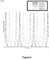
- fig. 4 which shows a time domain signal data diagram showing the firing sequence of the engine provided by the embodiment of the present application, as shown in fig. 4 , the time domain signal data within 0.5 seconds is displayed in the diagram.
- the firing sequence of the cylinders in the engine is as follows: cylinder 1, cylinder 3, cylinder 4 and cylinder 2.
- S102 Calculating a first parameter sequence according to the cylinder pressure sequence, wherein the first parameter sequence is a parameter sequence in a time domain, and the first parameter sequence comprises one or more of a top surface cylinder force sequence, a top surface cylinder force rise rate sequence, a side surface cylinder force sequence and a side surface cylinder force rise rate sequence.
- the first parameter sequence can be calculated according to the cylinder pressure sequence, wherein the first parameter sequence can include one or more of a top surface cylinder force sequence, a top surface cylinder force rise rate sequence, a side surface cylinder force sequence and a side surface cylinder force rise rate sequence.
- adjacent cylinder pressures P c are applied for differential approximate calculation, and the adjacent cylinder pressures referred to herein may be cylinder pressures with adjacent crank angles or adjacent cylinder pressures at corresponding moments.
- the first parameter sequence calculated according to the cylinder pressure sequence may still include a cylinder pressure sequence, and the calculated first parameter sequence may further include a cylinder pressure rise rate sequence, a top surface cylinder force sequence, a top surface cylinder force rise rate sequence, a side surface cylinder force sequence, and a side surface cylinder force rise rate sequence.
- Table 1 Parameters of four cylinders Name Symbol Unit Value Firing sequence 1-3-4-2 Cylinder diameter D mm 83 Strokes 2r mm 92 Connecting rod length 1 mm 142 Crank length r mm 46 Equivalent clearance height ⁇ mm 5
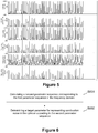
- this diagram shows a time domain diagram corresponding to a first parameter sequence provided by an embodiment of the present application, as shown in fig. 5 , the figure includes a time domain diagram corresponding to a cylinder pressure sequence, a time domain diagram corresponding to a cylinder pressure rise rate sequence, a time domain diagram corresponding to a top surface cylinder force sequence, a time domain diagram corresponding to a top surface cylinder force rise rate sequence, a time domain diagram corresponding to a side surface cylinder force sequence, and a time domain diagram corresponding to a side surface cylinder force rise rate sequence.
- parameters such as top surface cylinder force, side surface cylinder force, top surface cylinder force rise rate and side surface cylinder force rise rate are added to further consider the excitation of the combustion of combustible gas in the cylinder to the cylinder in the time history, so that the determined target parameters representing the combustion noise in the cylinder are more accurate and perfect.
- fig. 6 shows a flowchart of a method for determining a target parameter for representing in-cylinder combustion noise provided by an embodiment of the present application, as shown in fig. 6 , the method for determining a target parameter for representing in-cylinder combustion noise according to a first parameter sequence in S103 may include:
- the first parameter sequence in the time domain can be converted into a corresponding parameter sequence in the frequency domain, and the first parameter sequence can be converted into a corresponding parameter sequence in the frequency domain as a second parameter sequence, thereby determining a target parameter for representing combustion noise in the cylinder according to the second parameter sequence.
- a corresponding second parameter sequence can be obtained for each parameter sequence in the first parameter sequence by Fourier transform, that is, the numerical value of the parameter data in each parameter sequence in the frequency domain can be obtained.
- fig. 7 shows another method flow chart provided by the embodiment of the present application for determining a target parameter for representing in-cylinder combustion noise, as shown in fig. 7 , the method for determining a target parameter for representing in-cylinder combustion noise in S602 according to a second parameter sequence may include:
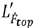
- the top surface cylinder force level L F top can be used as the combustion noise sound pressure level.
- the top surface cylinder force level sequence can be frequency weighted by frequency weighting to determine the corresponding top surface cylinder force value L F top ⁇ , which can be used as a target parameter to represent combustion noise in the cylinder.
- the embodiment of the application provides two frequency weighting methods, namely an A-frequency weighting method and a Z frequency weighting method.
- the A-frequency weighting method can simulate the loudness of human ears to 40-square pure tones. When the signal passes, it can greatly attenuate the signals at low frequency and middle frequency (below 1000 Hz).
- the Z-frequency weighting method can be a non-weighting method.
- the side surface cylinder force level L F side can be used as the combustion noise sound pressure level.
- the side surface cylinder force level sequence can be weighted by frequency to determine the corresponding side surface cylinder force value L F side ⁇ .
- the target parameter comprises a corresponding top surface cylinder force value L F top ' and/or a side surface cylinder force value L F side '.
- the top surface cylinder force rise rate level L ⁇ top can be used as the combustion noise sound pressure level.
- frequency weighting can be carried out on the top surface cylinder force rise rate sequence by frequency weighting to determine the corresponding top surface cylinder force rise rate value L F ⁇ top ⁇ , which can be used as a target parameter for representing combustion noise in the cylinder.
- the side surface cylinder force rise rate level L ⁇ side can be used as the combustion noise sound pressure level.
- frequency weighting can be carried out on the side surface cylinder force rise rate sequence by frequency weighting to determine the corresponding side surface cylinder force rise rate value L F ⁇ side ⁇ , which can be used as a target parameter for representing combustion noise in the cylinder.
- the obtained third parameter sequence includes a corresponding top surface cylinder force rise rate sequence and/or a side surface cylinder force rise rate sequence
- the target parameter includes a corresponding top surface cylinder force rise rate value L F ⁇ top ⁇ and/or a side surface cylinder force rise rate value L F ⁇ side ⁇ .
- the cylinder pressure level L P c can be used as the combustion noise sound pressure level.
- the cylinder pressure rise rate level L ⁇ c can be used as the combustion noise sound pressure level.
- the top surface cylinder force rise rate sequence, the side surface cylinder force sequence and the side surface cylinder force rise rate sequence in the first parameter sequence can be determined according to the aforementioned manner, and will not be repeated here.
- the cylinder pressure level L P c , the cylinder pressure rise rate level L ⁇ c , the top surface cylinder force level L F top , the top surface cylinder force rise rate level L ⁇ top , the side surface cylinder force level L F side , and the side surface cylinder force rise rate level L ⁇ side can all be used as combustion noise sound pressure levels.
- FIG. 8 the figure shows a schematic diagram for determining a comprehensive value corresponding to the combustion noise sound pressure level of a cylinder provided by the embodiment of the present application, as shown in fig. 8 , a 1/3 octave calculation method is applied to one of four cylinders to collectively calculate the dispersed energy of the six combustion noise sound pressure levels (i.e.
- cylinder pressure level, cylinder pressure rise rate level, top surface cylinder force level, top surface cylinder force rise rate level, side surface cylinder force level and side surface cylinder force rise rate level) of the cylinder into the central frequency band of the octave, and the above six combustion noise sound pressure levels of each cylinder are simultaneously calculated by adopting an A-frequency weighting method, so that the comprehensive values corresponding to each combustion noise sound pressure level (i.e. cylinder pressure value, cylinder pressure rise rate value, top surface cylinder force value, top surface cylinder force rise rate value, side surface cylinder force value and side surface cylinder force value) can be obtained.
- the comprehensive value corresponding to each combustion noise sound pressure level can be determined by applying the method corresponding to fig. 8 . Therefore, the obtained comprehensive values corresponding to the combustion noise sound pressure levels of the four cylinders are shown in Table 2.
- the method for determining the combustion noise parameter not only considers the combustion noise parameter in the related technology, but also further considers the structural parameter of the engine cylinder, and further considers further describing the combustion noise by using the top surface cylinder force, the top surface cylinder force rise rate, the side surface cylinder force and the side surface cylinder force rise rate, so that the objective description of the combustion noise is more in line with the actual listening feeling of people, and the subjective feeling of the human body on the combustion noise is more objectively quantified.
- the method does not add more burden to the related technology, so the application surface of the method is the same as that of the related technology.
- the method can also be conveniently integrated into the test front end, so that the test equipment can directly output the test results of combustion noise.
- the embodiment of the present application also provides a device for determining the combustion noise parameter.
- fig. 9 shows a structural diagram of a device for determining the combustion noise parameter provided by the embodiment of the present application, the device includes:
- the determination unit 903 is specifically configured to:
- the determining unit 903 is further specifically configured to:
- the acquisition unit 901 is specifically configured to:
- parameters such as top surface cylinder force, side surface cylinder force, top surface cylinder force rise rate and side surface cylinder force rise rate are added to further consider the excitation of the combustion of combustible gas in the cylinder to the cylinder in the time history, so that the determined target parameters representing the combustion noise in the cylinder are more accurate and perfect.
Landscapes
- Engineering & Computer Science (AREA)
- Chemical & Material Sciences (AREA)
- Combustion & Propulsion (AREA)
- Mechanical Engineering (AREA)
- General Engineering & Computer Science (AREA)
- Physics & Mathematics (AREA)
- General Physics & Mathematics (AREA)
- Combined Controls Of Internal Combustion Engines (AREA)
Abstract
Description
- The application relates to the field of noise detection, in particular to a method and a device for determining combustion noise parameters.
- There is no uniform specification for describing the combustion noise in the cylinder of an automobile engine. At present, there are several commonly used representation methods in the world as follows: Liszt takes the cylinder pressure as the main representation parameter of combustion noise; Ricardo takes the cylinder pressure rise rate as the main representation parameter of combustion noise; FEV takes cylinder pressure and cylinder pressure rise rate as the main representation parameters of combined combustion noise; and there is also the application of cylinder pressure level and cylinder pressure rise rate level and other parameters to represent.
- The cylinder pressure can refer to the pressure in the cylinder of the internal combustion engine, with the symbol Pc and the unit Pascal (Pa). The cylinder pressure level may refer to the result obtained by multiplying the logarithm based on 10 by 10 after dividing the square of the cylinder pressure Pc by the square of the reference sound pressure P 0, the calculation formula is


c , the calculation formula is
- In fact, these representation parameters only relate to the combustion process of the combustible gas itself, and do not relate to the excitation of the cylinder by the combustion of the combustible gas in the cylinder in the time course, thus making the representation parameters of the combustion noise not accurate and perfect.
- Therefore, how to provide more accurate and perfect representation parameters of combustion noise is an urgent problem to be solved at present.
- In order to solve the above technical problems, the application provides a method and a device for determining combustion noise parameters, so that the determined target parameters representing combustion noise in a cylinder are more accurate and perfect.
- The embodiment of the application discloses the following technical schemes:
- The embodiment of the application provides a method for determining combustion noise parameters, which comprises the following steps:
- acquiring a cylinder pressure sequence, wherein the cylinder pressure sequence comprises cylinder pressures corresponding to different crank angles ϕ and corresponding moments tϕ ;
- calculating a first parameter sequence according to the cylinder pressure sequence, wherein the first parameter sequence is a parameter sequence in a time domain, and the first parameter sequence comprises one or more of a top surface cylinder force sequence, a top surface cylinder force rise rate sequence, a side surface cylinder force sequence and a side surface cylinder force rise rate sequence;
- wherein the top surface cylinder force in the top surface cylinder force sequence is Ftop = Pc · Stop , the top surface cylinder force rise rate in the top surface cylinder force rise rate sequence is


- determining a target parameter for representing combustion noise in a cylinder according to the first parameter sequence.
- Optionally, determining the target parameter for representing combustion noise in the cylinder according to the first parameter sequence comprises:
- calculating a second parameter sequence corresponding to the first parameter sequence in a frequency domain; and
- determining the target parameter for representing combustion noise in the cylinder according to the second parameter sequence.
- Optionally, determining the target parameter for representing combustion noise in the cylinder according to the second parameter sequence comprises:
- obtaining a corresponding third parameter sequence according to the second parameter sequence;
- performing frequency weighting on the third parameter sequence to determine a target parameter for representing combustion noise in a cylinder;
- wherein if the first parameter sequence comprises a top surface cylinder force sequence and/or a side surface cylinder force sequence, the third parameter sequence obtained by using

top ' and/or a side surface cylinder force value LFside ' and F 0 is a reference force; - if the first parameter sequence comprises a top surface cylinder force rise rate sequence and/or a side surface cylinder force rise rate sequence, the third parameter sequence obtained by using

top ' and/or a side surface cylinder force rise rate value LḞside ' and Ḟ 0 is a reference force rise rate. - Optionally, acquiring the cylinder pressure sequence comprises:
- acquiring a first cylinder pressure sequence according to a target crank angle interval;
- determining the cylinder pressure sequence according to the relationship between the crank angle and the corresponding moment;
- or,
- acquiring a second cylinder pressure sequence according to a target time interval;
- determining the cylinder pressure sequence according to the relationship between the crank angle and the corresponding moment.
- Optionally, the method further comprises:
setting the position of the crankshaft when the highest cylinder pressure is reached for the first time in the cylinder as the position of the crank angle ϕ = 0°, for the process of acquiring the first cylinder pressure sequence or the second cylinder pressure sequence. - The embodiment of the application also provides a device for determining combustion noise parameters, characterized in that the device comprises:
- an acquisition unit configured to acquire a cylinder pressure sequence including cylinder pressures Pc corresponding to different crank angles ϕ and corresponding moments tϕ ;
- a calculation unit configured to calculate a first parameter sequence according to the cylinder pressure sequence, wherein the first parameter sequence is a parameter sequence in a time domain, and the first parameter sequence comprises one or more of a top surface cylinder force sequence, a top surface cylinder force rise rate sequence, a side surface cylinder force sequence and a side surface cylinder force rise rate sequence;
- wherein the top surface cylinder force in the top surface cylinder force sequence is Ftop = Pc · Stop , the top surface cylinder force rise rate in the top surface cylinder force rise rate sequence is


- a determination unit configured to determine a target parameter for representing combustion noise in a cylinder according to the first parameter sequence.
- Optionally, the determining unit is specifically configured to:
- calculate a second parameter sequence corresponding to the first parameter sequence in a frequency domain;
- determine a target parameter for representing combustion noise in the cylinder according to the second parameter sequence.
- Optionally, the determining unit is further specifically configured to:
- obtain a corresponding third parameter sequence according to the second parameter sequence;
- perform frequency weighting on the third parameter sequence to determine a target parameter for representing combustion noise in a cylinder;
- wherein if the first parameter sequence comprises a top surface cylinder force sequence and/or a side surface cylinder force sequence, the third parameter sequence obtained by using
top ' and/or a side surface cylinder force value LFside ' and F 0 is a reference force; - if the first parameter sequence comprises a top surface cylinder force rise rate sequence and/or a side surface cylinder force rise rate sequence, the third parameter sequence obtained by using

top ' and/or a side surface cylinder force rise rate value LḞtop ', wherein Ḟ 0 is a reference force rise rate. - Optionally, the acquisition unit is specifically configured to:
- acquire a first cylinder pressure sequence according to a target crank angle interval;
- determine the cylinder pressure sequence according to the relationship between the crank angle and the corresponding moment;
- or,
- acquire a second cylinder pressure sequence according to a target time interval;
- determine the cylinder pressure sequence according to the relationship between the crank angle and the corresponding moment.
- Optionally, the acquisition unit is specifically configured to:
set the position of the crankshaft when the highest cylinder pressure is reached for the first time in the cylinder as the position of the crank angle ϕ = 0°, for the process of acquiring the first cylinder pressure sequence or the second cylinder pressure sequence. - As can be seen from the above technical scheme, a cylinder pressure sequence is obtained, and the cylinder pressure sequence comprises cylinder pressures Pc corresponding to different crank angles ϕ and corresponding moments tϕ ; calculating a first parameter sequence according to a cylinder pressure sequence, wherein the first parameter sequence is a parameter sequence in a time domain, and the first parameter sequence comprises one or more of a top surface cylinder force sequence, a top surface cylinder force rise rate sequence, a side surface cylinder force sequence and a side surface cylinder force rise rate sequence; the top surface cylinder force in top surface cylinder force sequence is Ftop = Pc · Stop , the top surface cylinder force rise rate in top surface cylinder force rise rate sequence is


- In order to more clearly explain the embodiment of the application or the technical scheme in the prior art, the following will briefly introduce the drawings needed in the description of the embodiment or the prior art. Apparently, the drawings in the following description are only some embodiments of the application. For those of ordinary skill in the art, other drawings can be obtained according to these drawings without creative labor.
-
Fig. 1 is a flowchart of a method for determining combustion noise parameters provided by an embodiment of the present application; -
Fig. 2 is a flowchart of a method for acquiring a cylinder pressure sequence provided by an embodiment of the present application; -
Fig. 3 is a flowchart of another method for acquiring a cylinder pressure sequence provided by an embodiment of the present application; -
Fig. 4 is a time domain signal data diagram showing a firing sequence of a transmitter according to an embodiment of the present application; -
Fig. 5 is a time domain diagram corresponding to a first parameter sequence provided by an embodiment of the present application; -
Fig. 6 is a flowchart of a method for determining a target parameter for representing combustion noise in a cylinder provided by an embodiment of the present application; -
Fig. 7 is a flowchart of another method for determining a target parameter for representing combustion noise in a cylinder provided by an embodiment of the present application; -
Fig. 8 is a schematic diagram for determining a comprehensive value corresponding to a combustion noise sound pressure level of a cylinder according to an embodiment of the present application; -
Fig. 9 is a structural diagram of a device for determining combustion noise parameters provided by an embodiment of the present application. - Embodiments of the present application will be described below with reference to the accompanying drawings.
- At present, the combustion noise in the cylinder of an automobile engine is mainly represented by parameters such as cylinder pressure, cylinder pressure level, cylinder pressure rise rate, cylinder pressure rise rate level and the like. These representation parameters only relate to the combustion process of combustible gas itself, and do not relate to the excitation of the cylinder by the combustion of combustible gas in the cylinder in the time course, thus causing the representation parameters of the combustion noise to be inaccurate and incomplete.
- Therefore, the embodiment of the application provides a method for determining combustion noise parameters, a cylinder pressure sequence is obtained, and the cylinder pressure sequence comprises cylinder pressures Pc corresponding to different crank angles ϕ and corresponding moments tϕ ; calculating a first parameter sequence according to a cylinder pressure sequence, wherein the first parameter sequence is a parameter sequence in a time domain, and the first parameter sequence comprises one or more of a top surface cylinder force sequence, a top surface cylinder force rise rate sequence, a side surface cylinder force sequence and a side surface cylinder force rise rate sequence; the top surface cylinder force in top surface cylinder force sequence is Ftop = Pc · Stop , the top surface cylinder force rise rate in top surface cylinder force rise rate sequence is

- Next, various parameters involved in the embodiments of this application will be introduced.
- Cylinder bore: the cylinder diameter of the engine, the symbol is D, and the unit is meters (m).
- Crank length: the distance between the two ends of the crank and the center of the connecting position, the symbol is r, and the unit is meters (m).
- Connecting rod length: the distance between the two ends of the connecting rod and the center of the connecting position, the symbol is L, and the unit is meters (m).
- Piston stroke: the distance between top and bottom dead centers, the symbol is s, and the unit is meters (m).
- Combustion chamber volume: when the piston is located at top dead center, the space formed above the top surface of the piston and below the bottom surface of the cylinder becomes the combustion chamber, and its volume is called the combustion chamber volume, the symbol is Vc and the unit is cubic meters (m3).
- Piston swept volume: the volume of the cylinder contained between the upper and lower dead centers, the symbol is Vs , and the unit is cubic meters (m3).
- Cylinder total volume: the sum of the piston swept volume and the combustion chamber volume, the symbol is Va, and the unit is cubic meters (m3).
- Cylinder equivalent top area/cylinder equivalent bottom area: the projected area of the top/bottom surface of a single cylinder, the symbol is Stop , the calculation formula is

- Compression ratio: the ratio of the cylinder total volume to the combustion chamber volume, the symbol is ε, and the calculation formula is

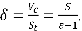
- Equivalent clearance height: the ratio of combustion chamber volume to cylinder equivalent top area, the symbol is δ, and calculation formula is
- Crankshaft angle: the angle at which the crankshaft turns after passing through a specified zero position for a period of time, the symbol is ϕ, and the unit is degrees (°).
- Zero position of crankshaft angle: the crankshaft angle at the top dead center position of the crankshaft, the symbol is ϕ 0, i.e. ϕ 0 = 0°.
- Cylinder side area: side area when a single cylinder works, the symbol is Sside , the calculation formula is

- Corresponding moment of crankshaft angle: the time elapsed from the zero position of crank angle to the crank angle ϕ, the symbol is tϕ , and the unit is seconds (s).
- Cylinder pressure: the pressure in the cylinder of the internal combustion engine, the symbol is Pc, and the unit is Pascal (Pa).
- Cylinder pressure level: the result obtained by multiplying the logarithm based on 10 by 10 after dividing the square of the cylinder pressure Pc by the square of the reference sound pressure P 0, the calculation formula is

- Cylinder pressure rise rate: the cylinder pressure change per unit crank angle, the symbol is Ṗc, the calculation formula is

- Cylinder pressure rise rate level: the result obtained by multiplying the logarithm based on 10 by 10 after the dividing the cylinder pressure rise rate Ṗc by the reference pressure rise rate Ṗ c0, the symbol is LṖ
c , the calculation formula is LṖc =
- Top surface cylinder force/bottom surface cylinder force: the pressure on the equivalent top surface/equivalent bottom surface in the cylinder, the symbol is Ftop , and the calculation formula is Ftop = Pc · Stop , and the unit is Newton (N).
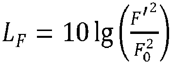
- Top surface cylinder force level: the result obtained by multiplying the logarithm based on 10 by 10 after the dividing the square of the top surface cylinder force Ftop by the square of the reference force F 0, the calculation formula is LF
top =
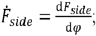
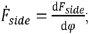
- Top surface cylinder force rise rate: the pressure change on the equivalent top surface in the cylinder per crank angle, the symbol is Ḟtop , the calculation formula is Ḟtop =

- Top surface cylinder force rise rate level: the result obtained by multiplying the logarithm based on 10 by 10 after the dividing the square of the top surface cylinder force rise rate Ḟtop by the square of the reference force rise rate Ḟ 0, the symbol is LḞ
top , the calculation formula is
- Side surface cylinder force: the pressure on the equivalent side surface in the cylinder, the symbol is Fside , and the calculation formula is Fside = Pc · Sside , and the unit is Newton (N).
- Side surface cylinder force level: the result obtained by multiplying the logarithm based on 10 by 10 after the dividing the square of the side surface cylinder force Fside by the square of the reference force F 0, the calculation formula is LF
side =
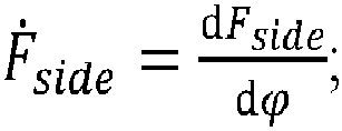
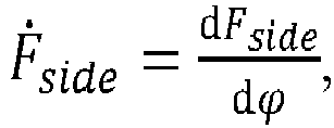
- Side surface cylinder force rise rate: the pressure change on the equivalent side surface in the cylinder per crank angle, the symbol is Ḟside, the calculation formula is

- Side surface cylinder force rise rate level: the result obtained by multiplying the logarithm based on 10 by 10 after the dividing the square of the side surface cylinder force rise rate Ḟside by the square of the reference force rise rate Ḟ 0, the symbol is LḞ
side , the calculation formula is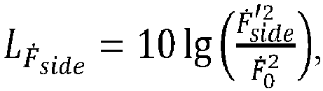
- Engine speed: the number of revolutions per minute of the engine, the symbol is n, and the unit is rpm.
- Combustion noise sound pressure level: representing any combustion noise sound pressure level, and the symbol is Lx.
- The method for determining the combustion noise parameters provided by the embodiment of the present application will be described below.
- Referring to
fig. 1 , the figure shows a flow chart of a method for determining combustion noise parameters provided by an embodiment of the present application. As shown infig. 1 , the method comprises:
S101: Acquiring a cylinder pressure sequence, wherein the cylinder pressure sequence comprises cylinder pressures Pc corresponding to different crank angles ϕ and moments tϕ . - In the embodiment of the application, a cylinder pressure sequence can be acquired, wherein the cylinder pressure sequence can include cylinder pressures Pc corresponding to different crank angles ϕ and moments tϕ .
- Next, the method of acquiring cylinder pressure sequence is introduced in detail.
- In one possible implementation, refer to
fig. 2 , which shows a flowchart of a method for acquiring a cylinder pressure sequence provided by an embodiment of the present application. The method for acquiring a cylinder pressure sequence in S101 may include: - S201: Acquiring a first cylinder pressure sequence according to a target crank angle interval.
- S202: Determining the cylinder pressure sequence according to the relationship between the crank angle and the corresponding moment.
- In the embodiment of the present application, a crank angle interval may be preset as the target crank angle interval, for example, the determined target crank angle interval is the crank angle interval of 1 degree. Then, in the combustion process of combustible gas in the engine cylinder, one cylinder pressure can be obtained at every other target crank angle interval according to the determined target crank angle interval to obtain one cylinder pressure sequence as the first cylinder pressure sequence. It can be understood that each cylinder pressure in the obtained first cylinder pressure sequence corresponds to one crank angle.
- In a specific implementation, the first cylinder pressure sequence can be measured by a cylinder pressure sensor.
- The moment corresponding to the crank angle may refer to the time elapsed from the zero position of the crank angle to the current crank angle ϕ, and the relationship between the crank angle and the corresponding moment may refer to ϕ = 6ntϕ , where n may refer to the rotational speed of the engine, and the unit of n may be revolutions per minute (rpm).
- Then, according to the relationship between the crank angle and the corresponding moment, the corresponding moment is determined for the crank angle of each cylinder pressure in the first cylinder pressure sequence, so that the cylinder pressure sequence can be determined.
- In one possible implementation, refer to
fig. 3 , which shows a flow chart of another method for acquiring a cylinder pressure sequence provided by an embodiment of the present application. the method for acquiring a cylinder pressure sequence in S101 may include: - S301: Acquiring a second cylinder pressure sequence according to a target time interval.
- S302: Determining the cylinder pressure sequence according to the relationship between the crank angle and the corresponding moment.
- In the embodiment of the present application, one time interval may be preset as the target time interval, for example, the determined target time interval is (1/25600) seconds. Then, during the combustion of combustible gas in the engine cylinder, one cylinder pressure can be obtained at every other target time interval according to the determined target time interval to obtain one cylinder pressure sequence as the second cylinder pressure sequence. It can be understood that each cylinder pressure in the obtained second cylinder pressure sequence corresponds to one moment.
- The relationship between the crank angle and the corresponding moment is described in S201-S202 and will not be described here.
- Then, the corresponding crank angle can be determined for the moment of each cylinder pressure in the first cylinder pressure sequence according to the relationship between the crank angle and the corresponding moment, so that the cylinder pressure sequence can be determined.
- It should be noted that the embodiment of the present application is not limited to the method of acquiring the cylinder pressure sequence in S101. For the above two modes, in one possible implementation, for the process of acquiring the first cylinder pressure sequence or the second cylinder pressure sequence, the position of the crankshaft when the highest cylinder pressure is reached for the first time in the cylinder may be set as the position of the crank angle ϕ = 0°, that is, in the process of acquiring the first cylinder pressure sequence or the second cylinder pressure sequence, the position of the crankshaft when the highest cylinder pressure is reached for the first time in the cylinder may be set as the zero position of the crank angle. Then, the crank angle corresponding to the cylinder pressure in the cylinder pressure sequence is adjusted according to the angle offset based on the crank angle zero position.
- Next, the method in S101 will be exemplified.
- In the embodiment of the present application, the method of S301-S302 (acquisition method of tracking time) is applied, and four groups of cylinder pressure sequences are acquired for four cylinders. Among them, the set target time interval is 0.5 seconds. By means of the cylinder pressure sensor, the cylinder pressure Pc in the engine cylinder is measured according to a target time interval to obtain a time domain signal of the cylinder pressure as a second cylinder pressure sequence. The sampling bandwidth is 25600 Hz. Referring to
fig. 4 which shows a time domain signal data diagram showing the firing sequence of the engine provided by the embodiment of the present application, as shown infig. 4 , the time domain signal data within 0.5 seconds is displayed in the diagram. As can be seen fromfig. 4 , the firing sequence of the cylinders in the engine is as follows:cylinder 1,cylinder 3,cylinder 4 andcylinder 2. - By using ϕ = 6ntϕ , the crank angle ϕ corresponding to the time of each cylinder pressure in the second cylinder pressure sequence is calculated (n = 750 rpm in this example). In this example, according to the firing sequence, the position of the crankshaft when each cylinder reaches the highest cylinder pressure for the first time is defined as the position where the crankshaft angle ϕ = 0 degrees, and the crankshaft angle is appropriately offset and adjusted, where the crankshaft angle offset for the first cylinder is -58.5 degrees, the crankshaft angle offset for the second cylinder is -58.5 degrees to 540 degrees, the crankshaft angle offset for the third cylinder is -58.5 degrees to 180 degrees, and the crankshaft angle offset for the fourth cylinder is -58.5 degrees to 360 degrees.
- S102: Calculating a first parameter sequence according to the cylinder pressure sequence, wherein the first parameter sequence is a parameter sequence in a time domain, and the first parameter sequence comprises one or more of a top surface cylinder force sequence, a top surface cylinder force rise rate sequence, a side surface cylinder force sequence and a side surface cylinder force rise rate sequence.
- In the embodiment of the application, the first parameter sequence can be calculated according to the cylinder pressure sequence, wherein the first parameter sequence can include one or more of a top surface cylinder force sequence, a top surface cylinder force rise rate sequence, a side surface cylinder force sequence and a side surface cylinder force rise rate sequence.
- Wherein if the calculated first parameter sequence includes a top surface cylinder force sequence, the way of obtaining the top surface cylinder force sequence includes: for each cylinder pressure Pc in the cylinder pressure sequence, the corresponding top surface cylinder force Ftop can be calculated by Ftop = Pc · Stop , and after calculating the corresponding top surface cylinder force Ftop based on each cylinder pressure Pc in the cylinder pressure sequence, the obtained top surface cylinder forces Ftop can be formed into a top surface cylinder force sequence.
- If the calculated first parameter sequence includes a top surface cylinder force rise rate sequence, the way of obtaining the top surface cylinder force rise rate sequence includes: for each cylinder pressure Pc in the cylinder pressure sequence, the corresponding top surface cylinder force rise rate Ḟtop can be calculated by Ḟtop =

- If the calculated first parameter sequence includes a side surface cylinder force sequence, the way of obtaining the side surface cylinder force sequence includes: for each cylinder pressure Pc in the cylinder pressure sequence, the corresponding side surface cylinder force Fside can be calculated by Fside = Pc · Sside , and after the corresponding side surface cylinder force Fside is calculated based on each cylinder pressure Pc in the cylinder pressure sequence, the obtained side surface cylinder forces Fside can be formed into a side surface cylinder force sequence.
- If the calculated first parameter sequence includes a side surface cylinder force rise rate sequence, the way of obtaining the side surface cylinder force rise rate sequence includes: for each cylinder pressure Pc in the cylinder pressure sequence, the corresponding side surface cylinder force rise rate Ḟside can be calculated by
- It should be noted that the principle of derivative calculation in the embodiment of the present application is that, as in

- Based on the example in S101 described above, the method of S102 will be illustrated next.
- In this example, the first parameter sequence calculated according to the cylinder pressure sequence may still include a cylinder pressure sequence, and the calculated first parameter sequence may further include a cylinder pressure rise rate sequence, a top surface cylinder force sequence, a top surface cylinder force rise rate sequence, a side surface cylinder force sequence, and a side surface cylinder force rise rate sequence.
- Among them, the parameters of the four aforementioned cylinders are shown in Table 1.
Table 1 Parameters of four cylinders Name Symbol Unit Value Firing sequence 1-3-4-2 Cylinder diameter D mm 83 Strokes 2r mm 92 Connecting rod length 1 mm 142 Crank length r mm 46 Equivalent clearance height δ mm 5 - The method for calculating the cylinder pressure rise rate sequence is as follows: according to

- According to Ftop = Pc · Stop and

- The method for calculating the top surface cylinder force rise rate sequence is as follows: according to

- The method for calculating the side surface cylinder force sequence is as follows: according to Fside = Pc · Sside ,


- The method for calculating the side surface cylinder force rise rate sequence is as follows: according to

- Then, the processed first parameter sequence can be saved into a table, and time domain diagrams can be drawn according to time for the data of each parameter sequence in the first parameter sequence. Referring to
fig. 5 , this diagram shows a time domain diagram corresponding to a first parameter sequence provided by an embodiment of the present application, as shown infig. 5 , the figure includes a time domain diagram corresponding to a cylinder pressure sequence, a time domain diagram corresponding to a cylinder pressure rise rate sequence, a time domain diagram corresponding to a top surface cylinder force sequence, a time domain diagram corresponding to a top surface cylinder force rise rate sequence, a time domain diagram corresponding to a side surface cylinder force sequence, and a time domain diagram corresponding to a side surface cylinder force rise rate sequence. - S103: Determining target parameters for representing combustion noise in the cylinder according to the first parameter sequence.
- As can be seen from the above technical scheme, a cylinder pressure sequence is obtained, and the cylinder pressure sequence comprises cylinder pressures Pc corresponding to different crank angles ϕ and corresponding moments tϕ ; calculating a first parameter sequence according to a cylinder pressure sequence, wherein the first parameter sequence is a parameter sequence in a time domain, and the first parameter sequence comprises one or more of a top surface cylinder force sequence, a top surface cylinder force rise rate sequence, a side surface cylinder force sequence and a side surface cylinder force rise rate sequence; the top surface cylinder force in the top surface cylinder force sequence is Ftop = Pc · Stop , the top surface cylinder force rise rate in the top surface cylinder force rise rate sequence is Ḟtop =


- In one possible implementation, refer to
fig. 6 , which shows a flowchart of a method for determining a target parameter for representing in-cylinder combustion noise provided by an embodiment of the present application, as shown infig. 6 , the method for determining a target parameter for representing in-cylinder combustion noise according to a first parameter sequence in S103 may include: - S601: Calculating a second parameter sequence corresponding to the first parameter sequence in the frequency domain.
- S602: Determining a target parameter for representing combustion noise in the cylinder according to the second parameter sequence.
- In the embodiment of the present application, the first parameter sequence in the time domain can be converted into a corresponding parameter sequence in the frequency domain, and the first parameter sequence can be converted into a corresponding parameter sequence in the frequency domain as a second parameter sequence, thereby determining a target parameter for representing combustion noise in the cylinder according to the second parameter sequence.
- In a specific implementation, a corresponding second parameter sequence can be obtained for each parameter sequence in the first parameter sequence by Fourier transform, that is, the numerical value of the parameter data in each parameter sequence in the frequency domain can be obtained.
- In one possible implementation, refer to
fig. 7 , which shows another method flow chart provided by the embodiment of the present application for determining a target parameter for representing in-cylinder combustion noise, as shown infig. 7 , the method for determining a target parameter for representing in-cylinder combustion noise in S602 according to a second parameter sequence may include: - S701: Obtaining a corresponding third parameter sequence according to the second parameter sequence.
- S702: Performing frequency weighting on the third parameter sequence to determine a target parameter for representing combustion noise in the cylinder.
- In the embodiment of the application, if the first parameter sequence includes a top surface cylinder force sequence, the second parameter sequence includes a corresponding top surface cylinder force sequence in the frequency domain, so that a top surface cylinder force level LF
top corresponding to each parameter is obtained by
top are formed into a top surface cylinder force level sequence, so that the obtained third parameter sequence includes a corresponding top surface cylinder force level sequence. Among them, the top surface cylinder force level LFtop can be used as the combustion noise sound pressure level. - Then, the top surface cylinder force level sequence can be frequency weighted by frequency weighting to determine the corresponding top surface cylinder force value
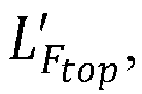
- The embodiment of the application provides two frequency weighting methods, namely an A-frequency weighting method and a Z frequency weighting method. The A-frequency weighting method can simulate the loudness of human ears to 40-square pure tones. When the signal passes, it can greatly attenuate the signals at low frequency and middle frequency (below 1000 Hz). The Z-frequency weighting method can be a non-weighting method.
- If the first parameter sequence includes a side surface cylinder force sequence, the second parameter sequence includes a corresponding side surface cylinder force sequence in the frequency domain, so that the side surface cylinder force level LF
side corresponding to each parameter is obtained by
side are formed into a side surface cylinder force level sequence, so that the obtained third parameter sequence includes the corresponding side surface cylinder force level sequence. Among them, the side surface cylinder force level LFside can be used as the combustion noise sound pressure level. - Then, the side surface cylinder force level sequence can be weighted by frequency to determine the corresponding side surface cylinder force value

- That is, if the first parameter sequence comprises a top surface cylinder force sequence and/or a side surface cylinder force sequence, the third parameter sequence obtained by using

top ' and/or a side surface cylinder force value LFside '. - If the first parameter sequence includes a top surface cylinder force rise rate sequence and the second parameter sequence includes a corresponding top surface cylinder force rise rate sequence in the frequency domain, the top surface cylinder force rise rate level LḞ
top corresponding to each parameter is obtained by
top are formed into a top surface cylinder force rise rate level sequence, so that the obtained third parameter sequence includes a corresponding top surface cylinder force rise rate level sequence. Among them, the top surface cylinder force rise rate level LḞtop can be used as the combustion noise sound pressure level. - Then, frequency weighting can be carried out on the top surface cylinder force rise rate sequence by frequency weighting to determine the corresponding top surface cylinder force rise rate value

- If the first parameter sequence includes a side surface cylinder force rise rate sequence, the second parameter sequence includes a corresponding side surface cylinder force rise rate sequence in the frequency domain, so that the side surface cylinder force rise rate level LḞ
side corresponding to each parameter is obtained by
side are formed into a side surface cylinder force rise rate level sequence, so that the obtained third parameter sequence includes the corresponding side surface cylinder force rise rate level sequence. Among them, the side surface cylinder force rise rate level LḞside can be used as the combustion noise sound pressure level. - Then, frequency weighting can be carried out on the side surface cylinder force rise rate sequence by frequency weighting to determine the corresponding side surface cylinder force rise rate value

- That is, if the first parameter sequence includes a top surface cylinder force rise rate sequence and/or a side surface cylinder force rise rate sequence, the obtained third parameter sequence includes a corresponding top surface cylinder force rise rate sequence and/or a side surface cylinder force rise rate sequence, and the target parameter includes a corresponding top surface cylinder force rise rate value


- Based on the example in the foregoing S102, the methods of S701-S702 will be illustrated next.
- For the cylinder pressure sequence in the first parameter sequence, the second parameter sequence includes the corresponding cylinder pressure sequence in the frequency domain, so that the cylinder pressure level LP
c corresponding to each parameter is obtained by
c are formed into the cylinder pressure level sequence, so that the obtained third parameter sequence includes the corresponding cylinder pressure level sequence. Among them, the cylinder pressure level LPc can be used as the combustion noise sound pressure level. - For the cylinder pressure rise rate sequence in the first parameter sequence, the second parameter sequence includes the corresponding cylinder pressure rise rate sequence in the frequency domain, so that the cylinder pressure rise rate level LṖ
c corresponding to each parameter is obtained by
c are formed into the cylinder pressure rise rate level sequence, so that the obtained third parameter sequence includes the corresponding cylinder pressure rise rate level sequence. Among them, the cylinder pressure rise rate level LṖc can be used as the combustion noise sound pressure level. - In addition, for the top surface cylinder force sequence, the top surface cylinder force rise rate sequence, the side surface cylinder force sequence and the side surface cylinder force rise rate sequence in the first parameter sequence, the corresponding top surface cylinder force level sequence, the top surface cylinder force rise rate sequence, the side surface cylinder force level sequence and the side surface cylinder force rise rate sequence can be determined according to the aforementioned manner, and will not be repeated here.
- That is, the cylinder pressure level LP
c , the cylinder pressure rise rate level LṖc , the top surface cylinder force level LFtop , the top surface cylinder force rise rate level LḞtop , the side surface cylinder force level LFside , and the side surface cylinder force rise rate level LḞside provided by the embodiment of the present application can all be used as combustion noise sound pressure levels. - Then, referring to
fig. 8 , the figure shows a schematic diagram for determining a comprehensive value corresponding to the combustion noise sound pressure level of a cylinder provided by the embodiment of the present application, as shown infig. 8 , a 1/3 octave calculation method is applied to one of four cylinders to collectively calculate the dispersed energy of the six combustion noise sound pressure levels (i.e. cylinder pressure level, cylinder pressure rise rate level, top surface cylinder force level, top surface cylinder force rise rate level, side surface cylinder force level and side surface cylinder force rise rate level) of the cylinder into the central frequency band of the octave, and the above six combustion noise sound pressure levels of each cylinder are simultaneously calculated by adopting an A-frequency weighting method, so that the comprehensive values corresponding to each combustion noise sound pressure level (i.e. cylinder pressure value, cylinder pressure rise rate value, top surface cylinder force value, top surface cylinder force rise rate value, side surface cylinder force value and side surface cylinder force value) can be obtained. - In addition, for the remaining three of the four cylinders, the comprehensive value corresponding to each combustion noise sound pressure level can be determined by applying the method corresponding to
fig. 8 . Therefore, the obtained comprehensive values corresponding to the combustion noise sound pressure levels of the four cylinders are shown in Table 2.Table 2 Comprehensive values corresponding to combustion noise sound pressure levels of four cylinders 




Cylinder 1178.13 82.13 38.82 36.79 36.79 24.21 Cylinder 2177.87 78.70 38.56 33.36 33.36 23.87 Cylinder 3177.91 78.12 38.60 32.78 32.78 23.78 Cylinder 4177.81 77.24 38.50 31.90 31.90 47.90 - According to the technical scheme provided by the embodiment of the application, the method for determining the combustion noise parameter provided by the embodiment of the application not only considers the combustion noise parameter in the related technology, but also further considers the structural parameter of the engine cylinder, and further considers further describing the combustion noise by using the top surface cylinder force, the top surface cylinder force rise rate, the side surface cylinder force and the side surface cylinder force rise rate, so that the objective description of the combustion noise is more in line with the actual listening feeling of people, and the subjective feeling of the human body on the combustion noise is more objectively quantified.
- The method does not add more burden to the related technology, so the application surface of the method is the same as that of the related technology. The method can also be conveniently integrated into the test front end, so that the test equipment can directly output the test results of combustion noise.
- The embodiment of the present application also provides a device for determining the combustion noise parameter. refer to
fig. 9 , which shows a structural diagram of a device for determining the combustion noise parameter provided by the embodiment of the present application, the device includes: - an
acquisition unit 901, configured to acquire a cylinder pressure sequence, wherein the cylinder pressure sequence includes cylinder pressures Pc corresponding to different crank angles ϕ and corresponding moments tϕ ; - a
calculation unit 902, configured to calculate a first parameter sequence according to the cylinder pressure sequence, wherein the first parameter sequence is a parameter sequence in a time domain, and the first parameter sequence includes one or more of a top surface cylinder force sequence, a top surface cylinder force rise rate sequence, a side surface cylinder force sequence, and a side surface cylinder force rise rate sequence; - wherein the top surface cylinder force in the top surface cylinder force sequence is Ftop = Pc · Stop , the top surface cylinder force rise rate in the top surface cylinder force rise rate sequence is

- a determining
unit 903, configured to determine a target parameter for representing combustion noise in the cylinder according to the first parameter sequence. - In one possible implementation, the
determination unit 903 is specifically configured to: - calculate a second parameter sequence corresponding to the first parameter sequence in a frequency domain; and
- determine a target parameter for representing combustion noise in the cylinder according to the second parameter sequence.
- In one possible implementation, the determining
unit 903 is further specifically configured to: - obtain a corresponding third parameter sequence according to the second parameter sequence; and
- perform frequency weighting on the third parameter sequence to determine a target parameter for representing combustion noise in a cylinder;
- wherein if the first parameter sequence comprises a top surface cylinder force sequence and/or a side surface cylinder force sequence, the third parameter sequence obtained by using

side ', and F 0 is a reference force; - if the first parameter sequence comprises a top surface cylinder force rise rate sequence and/or a side surface cylinder force rise rate sequence, the third parameter sequence obtained by using

top ' and/or a side surface cylinder force rise rate value LḞside ', and Ḟ 0 is a reference force rise rate. - In one possible implementation, the
acquisition unit 901 is specifically configured to: - acquire a first cylinder pressure sequence according to a target crank angle interval; and
- determine the cylinder pressure sequence according to the relationship between the crank angle and the corresponding moment;
- or,
- acquire a second cylinder pressure sequence according to a target time interval; and
- determine the cylinder pressure sequence according to the relationship between the crank angle and the corresponding moment.
- In one possible implementation, the
acquisition unit 901 is specifically configured to:
setting the position of the crankshaft when the highest cylinder pressure is reached for the first time in the cylinder as the position of the crank angle ϕ = 0°, for the process of acquiring said first cylinder pressure sequence or said second cylinder pressure sequence. - As can be seen from the above technical scheme, a cylinder pressure sequence is obtained, and the cylinder pressure sequence comprises cylinder pressures Pc corresponding to different crank angles ϕ and corresponding moments tϕ ; calculating a first parameter sequence according to a cylinder pressure sequence, wherein the first parameter sequence is a parameter sequence in a time domain, and the first parameter sequence comprises one or more of a top surface cylinder force sequence, a top surface cylinder force rise rate sequence, a side surface cylinder force sequence and a side surface cylinder force rise rate sequence; the top surface cylinder force in top surface cylinder force sequence is Ftop = Pc · Stop , the top surface cylinder force rise rate in top surface cylinder force rise rate sequence is


- From the description of the above embodiments, it is clear to those skilled in the art that all or part of the steps in the method of the above embodiments can be implemented by means of software plus necessary general hardware platforms. Based on this understanding, the technical solution of the present application can be embodied in the form of a software product, which can be stored in a storage medium such as ROM/RAM, magnetic disk, optical disk, etc., and includes several instructions to cause a computer device (which can be a personal computer, a server, or a network communication device such as a media gateway, etc.) to perform the methods described in various embodiments or some parts of embodiments of the present application.
- It should be noted that various embodiments in this specification are described in a progressive manner, and each embodiment focuses on the differences from other embodiments, and the same similar parts between various embodiments can be referred to each other. For the device disclosed in the embodiment, since it corresponds to the method disclosed in the embodiment, the description is relatively simple, and the relevant parts can be explained in the method section.
- It should also be noted that in this document, relational terms such as first and second, etc. are only used to distinguish one entity or operation from another entity or operation, and do not necessarily require or imply any such actual relationship or order between these entities or operations. Moreover, the terms "comprising", "including" or any other variation thereof are intended to cover a non-exclusive inclusion, such that a process, method, article, or apparatus that comprises a list of elements does not include only those elements but also other elements not expressly listed or inherent to such process, method, article, or apparatus. Without further limitation, an element defined by the statement "including" does not exclude the presence of another identical element in a process, method, article or device that includes the element.
- The above description of the disclosed embodiments enables those skilled in the art to make or use the present application. Various modifications to these embodiments will be apparent to those skilled in the art, and the general principles defined herein may be implemented in other embodiments without departing from the spirit or scope of the present application. Therefore, this application is not to be limited to the embodiments shown herein but is to be accorded the widest scope consistent with the principles and novel features disclosed herein.
Claims (10)
- A method for determining combustion noise parameters, characterized in that said method comprises:acquiring a cylinder pressure sequence, wherein said cylinder pressure sequence comprises cylinder pressures corresponding to different crank angles ϕ and corresponding moments tϕ ;calculating a first parameter sequence according to said cylinder pressure sequence, wherein said first parameter sequence is a parameter sequence in a time domain, and said first parameter sequence comprises one or more of a top surface cylinder force sequence, a top surface cylinder force rise rate sequence, a side surface cylinder force sequence and a side surface cylinder force rise rate sequence;wherein the top surface cylinder force in said top surface cylinder force sequence is Ftop = Pc · Stop , the top surface cylinder force rise rate in said top surface cylinder force rise rate sequence is

 determining a target parameter for representing combustion noise in a cylinder according to said first parameter sequence.
 - The method according to claim 1, characterized in that determining the target parameter for representing combustion noise in the cylinder according to said first parameter sequence comprises:calculating a second parameter sequence corresponding to said first parameter sequence in a frequency domain; anddetermining the target parameter for representing combustion noise in the cylinder according to said second parameter sequence.
- The method according to claim 2, characterized in that determining the target parameter for representing combustion noise in the cylinder according to said second parameter sequence comprises:obtaining a corresponding third parameter sequence according to said second parameter sequence;performing frequency weighting on said third parameter sequence to determine a target parameter for representing combustion noise in a cylinder;wherein if said first parameter sequence comprises a top surface cylinder force sequence and/or a side surface cylinder force sequence, said third parameter sequenceobtained by using

top ' and/or a side surface cylinder force value LFside ', and F 0 is a reference force;if said first parameter sequence comprises a top surface cylinder force rise rate sequence and/or a side surface cylinder force rise rate sequence, said third parameter sequence obtained by using
top ' and/or a side surface cylinder force rise rate value LḞside ', and Ḟ 0 is a reference force rise rate. - The method according to claim 1, characterized in that acquiring the cylinder pressure sequence comprises:acquiring a first cylinder pressure sequence according to a target crank angle interval;determining said cylinder pressure sequence according to the relationship between the crank angle and the corresponding moment;or,acquiring a second cylinder pressure sequence according to a target time interval;determining said cylinder pressure sequence according to the relationship between said crank angle and the corresponding moment.
- The method of claim 4, characterized by further comprising:
setting the position of the crankshaft when the highest cylinder pressure is reached for the first time in the cylinder as the position of the crank angle ϕ = 0°, for the process of acquiring said first cylinder pressure sequence or said second cylinder pressure sequence. - A device for determining combustion noise parameters, characterized in that the device comprises:an acquisition unit configured to acquire a cylinder pressure sequence including cylinder pressures Pc corresponding to different crank angles ϕ and corresponding moments tϕ ;a calculation unit configured to calculate a first parameter sequence according to the cylinder pressure sequence, wherein said first parameter sequence is a parameter sequence in a time domain, and said first parameter sequence comprises one or more of a top surface cylinder force sequence, a top surface cylinder force rise rate sequence, a side surface cylinder force sequence and a side surface cylinder force rise rate sequence;wherein the top surface cylinder force in said top surface cylinder force sequence is Ftop = Pc · Stop , the top surface cylinder force rise rate in said top surface cylinder force rise rate sequence is

 a determination unit configured to determine a target parameter for representing combustion noise in a cylinder according to the first parameter sequence.
 - The device according to claim 6, characterized in that the determining unit is specifically configured to:calculate a second parameter sequence corresponding to said first parameter sequence in a frequency domain;determine a target parameter for representing combustion noise in the cylinder according to the second parameter sequence.
- The device according to claim 7, characterized in that said determining unit is further specifically configured to:obtain a corresponding third parameter sequence according to said second parameter sequence;perform frequency weighting on said third parameter sequence to determine a target parameter for representing combustion noise in a cylinder;wherein if said first parameter sequence comprises a top surface cylinder force sequence and/or a side surface cylinder force sequence, said third parameter sequenceobtained by using
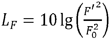
top ' and/or a side surface cylinder force value LFside ', and F 0 is a reference force;if said first parameter sequence comprises a top surface cylinder force rise rate sequence and/or a side surface cylinder force rise rate sequence, said third parameter
sequence obtained by using
top ' and/or a side surface cylinder force rise rate value LḞtop ',wherein Ḟ 0 is a reference force rise rate. - The device according to claim 6, characterized in that said acquisition unit is specifically configured to:acquire a first cylinder pressure sequence according to a target crank angle interval;determine said cylinder pressure sequence according to the relationship between the crank angle and the corresponding moment;or,acquire a second cylinder pressure sequence according to a target time interval;determine said cylinder pressure sequence according to the relationship between said crank angle and the corresponding moment.
- The device according to claim 9, characterized in that the acquisition unit is specifically configured to:
set the position of the crankshaft when the highest cylinder pressure is reached for the first time in the cylinder as the position of the crank angle ϕ = 0°, for the process of acquiring said first cylinder pressure sequence or said second cylinder pressure sequence.
Applications Claiming Priority (1)
| Application Number | Priority Date | Filing Date | Title |
|---|---|---|---|
| CN201910906988.0A CN112632690B (en) | 2019-09-24 | 2019-09-24 | Method and device for determining combustion noise parameters |
Publications (2)
| Publication Number | Publication Date |
|---|---|
| EP3798436A1 true EP3798436A1 (en) | 2021-03-31 |
| EP3798436B1 EP3798436B1 (en) | 2024-04-10 |
Family
ID=70775258
Family Applications (1)
| Application Number | Title | Priority Date | Filing Date |
|---|---|---|---|
| EP20174770.6A Active EP3798436B1 (en) | 2019-09-24 | 2020-05-14 | Method and device for determining combustion noise parameters |
Country Status (4)
| Country | Link |
|---|---|
| US (1) | US11067010B2 (en) |
| EP (1) | EP3798436B1 (en) |
| JP (1) | JP7516113B2 (en) |
| CN (1) | CN112632690B (en) |
Citations (5)
| Publication number | Priority date | Publication date | Assignee | Title |
|---|---|---|---|---|
| EP1316704A2 (en) * | 2001-12-01 | 2003-06-04 | Robert Bosch Gmbh | Method and apparatus for controlling an internal combustion engine |
| WO2007091735A1 (en) * | 2006-02-09 | 2007-08-16 | Toyota Jidosha Kabushiki Kaisha | Stop position control apparatus for internal combustion engine |
| DE102013109889A1 (en) * | 2012-12-14 | 2014-06-18 | Hyundai Motor Company | Fuel injection quantity compensation method |
| DE102015210616A1 (en) * | 2014-10-20 | 2016-04-21 | Hyundai Motor Company | Method for controlling engine combustion noise |
| DE102017204579A1 (en) * | 2016-09-27 | 2018-03-29 | Mitsubishi Electric Corporation | Control and control method for internal combustion engine |
Family Cites Families (7)
| Publication number | Priority date | Publication date | Assignee | Title |
|---|---|---|---|---|
| JP3231536B2 (en) * | 1993-02-25 | 2001-11-26 | トヨタ自動車株式会社 | Diagnosis method of press machine abnormality |
| JP4672588B2 (en) * | 2006-04-03 | 2011-04-20 | トヨタ自動車株式会社 | Combustion noise calculation device and combustion noise control system for internal combustion engine |
| US8229655B2 (en) * | 2009-05-19 | 2012-07-24 | GM Global Technology Operations LLC | Fuel injection and combustion fault diagnostics using cylinder pressure sensor |
| KR101856243B1 (en) * | 2012-07-03 | 2018-05-09 | 현대자동차주식회사 | Method of controlling engine noise including combustion noise of internal combustion engine |
| CN103850852B (en) * | 2012-12-03 | 2016-08-03 | 上海汽车集团股份有限公司 | For detecting the system and method for electromotor early combustion |
| CN104063553A (en) * | 2014-07-04 | 2014-09-24 | 上汽通用五菱汽车股份有限公司 | Optimization design method of combustion system of engine |
| AT518869B1 (en) * | 2016-09-28 | 2018-02-15 | Avl List Gmbh | Method for creating a suppressed combustion chamber signal data stream |
-
2019
- 2019-09-24 CN CN201910906988.0A patent/CN112632690B/en active Active
-
2020
- 2020-05-14 EP EP20174770.6A patent/EP3798436B1/en active Active
- 2020-05-14 US US15/931,900 patent/US11067010B2/en active Active
- 2020-05-29 JP JP2020093821A patent/JP7516113B2/en active Active
Patent Citations (5)
| Publication number | Priority date | Publication date | Assignee | Title |
|---|---|---|---|---|
| EP1316704A2 (en) * | 2001-12-01 | 2003-06-04 | Robert Bosch Gmbh | Method and apparatus for controlling an internal combustion engine |
| WO2007091735A1 (en) * | 2006-02-09 | 2007-08-16 | Toyota Jidosha Kabushiki Kaisha | Stop position control apparatus for internal combustion engine |
| DE102013109889A1 (en) * | 2012-12-14 | 2014-06-18 | Hyundai Motor Company | Fuel injection quantity compensation method |
| DE102015210616A1 (en) * | 2014-10-20 | 2016-04-21 | Hyundai Motor Company | Method for controlling engine combustion noise |
| DE102017204579A1 (en) * | 2016-09-27 | 2018-03-29 | Mitsubishi Electric Corporation | Control and control method for internal combustion engine |
Also Published As
| Publication number | Publication date |
|---|---|
| US20210087986A1 (en) | 2021-03-25 |
| EP3798436B1 (en) | 2024-04-10 |
| CN112632690A (en) | 2021-04-09 |
| CN112632690B (en) | 2023-08-01 |
| US11067010B2 (en) | 2021-07-20 |
| JP7516113B2 (en) | 2024-07-16 |
| JP2021050731A (en) | 2021-04-01 |
Similar Documents
| Publication | Publication Date | Title |
|---|---|---|
| Hudson et al. | Knock measurement for fuel evaluation in spark ignition engines | |
| Puzinauskas | Examination of methods used to characterize engine knock | |
| Terasawa et al. | The thirteen colors of timbre | |
| CN109765426B (en) | A fast identification method of system model parameters based on wide-spectrum excitation signal | |
| EP3798436B1 (en) | Method and device for determining combustion noise parameters | |
| KR101307017B1 (en) | Apparatus for identifying a non-uniform share of cylinder power in an internal combustion piston engine system | |
| JP2020186683A (en) | Learning device and estimation device | |
| CN111666817B (en) | System and method for determining main lobe time delay resolution of LFM signal of radar equipment | |
| US9334799B2 (en) | Method of estimating the intensity of the knocking of an internal combustion engine by inversion of a wave equation | |
| CN109186509B (en) | Measuring device and measuring method for deformation amount of piston lip of variable gap sealing hydraulic cylinder | |
| Lenormand | Sca2003-52: Interpretation of mercury injection curves to derive pore size distribution | |
| DE602005005195T2 (en) | METHOD FOR FILTERING PUMP NOISE | |
| JP2012103157A (en) | Method and device for determining knocking | |
| DE19931985A1 (en) | Method for determining the indicated mean pressure of internal combustion engines | |
| JP4116813B2 (en) | Internal combustion engine knock detection device | |
| JP3083546B2 (en) | Engine knock detection method | |
| Pan et al. | Identification of start of combustion based on contribution level of principal component in vibration signal of cylinder head surface | |
| Egan et al. | The error due to masking in the measurement of aural harmonics by the method of best beats | |
| JP2784197B2 (en) | Frequency analysis method and apparatus | |
| JP2020186719A (en) | Knocking determination device | |
| DE102019132011A1 (en) | Method for determining an engine parameter | |
| JP7623933B2 (en) | Signal processing device and signal processing method | |
| CN119147150A (en) | Low-frequency-band cut-off frequency detection method for piezoelectric type shock wave pressure sensing system | |
| Babak et al. | Optimization of signal features under object's dynamic test | |
| SU1041894A1 (en) | Method of evaluating identity of internal combustion engine consequitive operation cycles |
Legal Events
| Date | Code | Title | Description |
|---|---|---|---|
| PUAI | Public reference made under article 153(3) epc to a published international application that has entered the european phase |
Free format text: ORIGINAL CODE: 0009012 |
|
| STAA | Information on the status of an ep patent application or granted ep patent |
Free format text: STATUS: THE APPLICATION HAS BEEN PUBLISHED |
|
| AK | Designated contracting states |
Kind code of ref document: A1 Designated state(s): AL AT BE BG CH CY CZ DE DK EE ES FI FR GB GR HR HU IE IS IT LI LT LU LV MC MK MT NL NO PL PT RO RS SE SI SK SM TR |
|
| AX | Request for extension of the european patent |
Extension state: BA ME |
|
| STAA | Information on the status of an ep patent application or granted ep patent |
Free format text: STATUS: REQUEST FOR EXAMINATION WAS MADE |
|
| 17P | Request for examination filed |
Effective date: 20220103 |
|
| RBV | Designated contracting states (corrected) |
Designated state(s): AL AT BE BG CH CY CZ DE DK EE ES FI FR GB GR HR HU IE IS IT LI LT LU LV MC MK MT NL NO PL PT RO RS SE SI SK SM TR |
|
| GRAP | Despatch of communication of intention to grant a patent |
Free format text: ORIGINAL CODE: EPIDOSNIGR1 |
|
| STAA | Information on the status of an ep patent application or granted ep patent |
Free format text: STATUS: GRANT OF PATENT IS INTENDED |
|
| INTG | Intention to grant announced |
Effective date: 20231122 |
|
| GRAS | Grant fee paid |
Free format text: ORIGINAL CODE: EPIDOSNIGR3 |
|
| GRAA | (expected) grant |
Free format text: ORIGINAL CODE: 0009210 |
|
| STAA | Information on the status of an ep patent application or granted ep patent |
Free format text: STATUS: THE PATENT HAS BEEN GRANTED |
|
| AK | Designated contracting states |
Kind code of ref document: B1 Designated state(s): AL AT BE BG CH CY CZ DE DK EE ES FI FR GB GR HR HU IE IS IT LI LT LU LV MC MK MT NL NO PL PT RO RS SE SI SK SM TR |
|
| REG | Reference to a national code |
Ref country code: GB Ref legal event code: FG4D |
|
| REG | Reference to a national code |
Ref country code: CH Ref legal event code: EP |
|
| REG | Reference to a national code |
Ref country code: DE Ref legal event code: R096 Ref document number: 602020028613 Country of ref document: DE |
|
| REG | Reference to a national code |
Ref country code: IE Ref legal event code: FG4D |
|
| P01 | Opt-out of the competence of the unified patent court (upc) registered |
Effective date: 20240528 |
|
| REG | Reference to a national code |
Ref country code: LT Ref legal event code: MG9D |
|
| REG | Reference to a national code |
Ref country code: NL Ref legal event code: MP Effective date: 20240410 |
|
| PG25 | Lapsed in a contracting state [announced via postgrant information from national office to epo] |
Ref country code: NL Free format text: LAPSE BECAUSE OF FAILURE TO SUBMIT A TRANSLATION OF THE DESCRIPTION OR TO PAY THE FEE WITHIN THE PRESCRIBED TIME-LIMIT Effective date: 20240410 |
|
| PG25 | Lapsed in a contracting state [announced via postgrant information from national office to epo] |
Ref country code: NL Free format text: LAPSE BECAUSE OF FAILURE TO SUBMIT A TRANSLATION OF THE DESCRIPTION OR TO PAY THE FEE WITHIN THE PRESCRIBED TIME-LIMIT Effective date: 20240410 |
|
| PG25 | Lapsed in a contracting state [announced via postgrant information from national office to epo] |
Ref country code: IS Free format text: LAPSE BECAUSE OF FAILURE TO SUBMIT A TRANSLATION OF THE DESCRIPTION OR TO PAY THE FEE WITHIN THE PRESCRIBED TIME-LIMIT Effective date: 20240810 |
|
| PG25 | Lapsed in a contracting state [announced via postgrant information from national office to epo] |
Ref country code: BG Free format text: LAPSE BECAUSE OF FAILURE TO SUBMIT A TRANSLATION OF THE DESCRIPTION OR TO PAY THE FEE WITHIN THE PRESCRIBED TIME-LIMIT Effective date: 20240410 |
|
| PG25 | Lapsed in a contracting state [announced via postgrant information from national office to epo] |
Ref country code: HR Free format text: LAPSE BECAUSE OF FAILURE TO SUBMIT A TRANSLATION OF THE DESCRIPTION OR TO PAY THE FEE WITHIN THE PRESCRIBED TIME-LIMIT Effective date: 20240410 Ref country code: FI Free format text: LAPSE BECAUSE OF FAILURE TO SUBMIT A TRANSLATION OF THE DESCRIPTION OR TO PAY THE FEE WITHIN THE PRESCRIBED TIME-LIMIT Effective date: 20240410 |
|
| PG25 | Lapsed in a contracting state [announced via postgrant information from national office to epo] |
Ref country code: GR Free format text: LAPSE BECAUSE OF FAILURE TO SUBMIT A TRANSLATION OF THE DESCRIPTION OR TO PAY THE FEE WITHIN THE PRESCRIBED TIME-LIMIT Effective date: 20240711 |
|
| PG25 | Lapsed in a contracting state [announced via postgrant information from national office to epo] |
Ref country code: PT Free format text: LAPSE BECAUSE OF FAILURE TO SUBMIT A TRANSLATION OF THE DESCRIPTION OR TO PAY THE FEE WITHIN THE PRESCRIBED TIME-LIMIT Effective date: 20240812 |
|
| PG25 | Lapsed in a contracting state [announced via postgrant information from national office to epo] |
Ref country code: ES Free format text: LAPSE BECAUSE OF FAILURE TO SUBMIT A TRANSLATION OF THE DESCRIPTION OR TO PAY THE FEE WITHIN THE PRESCRIBED TIME-LIMIT Effective date: 20240410 |
|
| PG25 | Lapsed in a contracting state [announced via postgrant information from national office to epo] |
Ref country code: PL Free format text: LAPSE BECAUSE OF FAILURE TO SUBMIT A TRANSLATION OF THE DESCRIPTION OR TO PAY THE FEE WITHIN THE PRESCRIBED TIME-LIMIT Effective date: 20240410 |
|
| PG25 | Lapsed in a contracting state [announced via postgrant information from national office to epo] |
Ref country code: LV Free format text: LAPSE BECAUSE OF FAILURE TO SUBMIT A TRANSLATION OF THE DESCRIPTION OR TO PAY THE FEE WITHIN THE PRESCRIBED TIME-LIMIT Effective date: 20240410 |
|
| PG25 | Lapsed in a contracting state [announced via postgrant information from national office to epo] |
Ref country code: PT Free format text: LAPSE BECAUSE OF FAILURE TO SUBMIT A TRANSLATION OF THE DESCRIPTION OR TO PAY THE FEE WITHIN THE PRESCRIBED TIME-LIMIT Effective date: 20240812 Ref country code: PL Free format text: LAPSE BECAUSE OF FAILURE TO SUBMIT A TRANSLATION OF THE DESCRIPTION OR TO PAY THE FEE WITHIN THE PRESCRIBED TIME-LIMIT Effective date: 20240410 Ref country code: NO Free format text: LAPSE BECAUSE OF FAILURE TO SUBMIT A TRANSLATION OF THE DESCRIPTION OR TO PAY THE FEE WITHIN THE PRESCRIBED TIME-LIMIT Effective date: 20240710 Ref country code: LV Free format text: LAPSE BECAUSE OF FAILURE TO SUBMIT A TRANSLATION OF THE DESCRIPTION OR TO PAY THE FEE WITHIN THE PRESCRIBED TIME-LIMIT Effective date: 20240410 Ref country code: IS Free format text: LAPSE BECAUSE OF FAILURE TO SUBMIT A TRANSLATION OF THE DESCRIPTION OR TO PAY THE FEE WITHIN THE PRESCRIBED TIME-LIMIT Effective date: 20240810 Ref country code: HR Free format text: LAPSE BECAUSE OF FAILURE TO SUBMIT A TRANSLATION OF THE DESCRIPTION OR TO PAY THE FEE WITHIN THE PRESCRIBED TIME-LIMIT Effective date: 20240410 Ref country code: GR Free format text: LAPSE BECAUSE OF FAILURE TO SUBMIT A TRANSLATION OF THE DESCRIPTION OR TO PAY THE FEE WITHIN THE PRESCRIBED TIME-LIMIT Effective date: 20240711 Ref country code: FI Free format text: LAPSE BECAUSE OF FAILURE TO SUBMIT A TRANSLATION OF THE DESCRIPTION OR TO PAY THE FEE WITHIN THE PRESCRIBED TIME-LIMIT Effective date: 20240410 Ref country code: ES Free format text: LAPSE BECAUSE OF FAILURE TO SUBMIT A TRANSLATION OF THE DESCRIPTION OR TO PAY THE FEE WITHIN THE PRESCRIBED TIME-LIMIT Effective date: 20240410 Ref country code: BG Free format text: LAPSE BECAUSE OF FAILURE TO SUBMIT A TRANSLATION OF THE DESCRIPTION OR TO PAY THE FEE WITHIN THE PRESCRIBED TIME-LIMIT Effective date: 20240410 Ref country code: RS Free format text: LAPSE BECAUSE OF FAILURE TO SUBMIT A TRANSLATION OF THE DESCRIPTION OR TO PAY THE FEE WITHIN THE PRESCRIBED TIME-LIMIT Effective date: 20240710 |
|
| REG | Reference to a national code |
Ref country code: AT Ref legal event code: UEP Ref document number: 1675125 Country of ref document: AT Kind code of ref document: T Effective date: 20240410 |
|
| REG | Reference to a national code |
Ref country code: CH Ref legal event code: PL |
|
| REG | Reference to a national code |
Ref country code: DE Ref legal event code: R097 Ref document number: 602020028613 Country of ref document: DE |
|
| PG25 | Lapsed in a contracting state [announced via postgrant information from national office to epo] |
Ref country code: DK Free format text: LAPSE BECAUSE OF FAILURE TO SUBMIT A TRANSLATION OF THE DESCRIPTION OR TO PAY THE FEE WITHIN THE PRESCRIBED TIME-LIMIT Effective date: 20240410 |
|
| PG25 | Lapsed in a contracting state [announced via postgrant information from national office to epo] |
Ref country code: LU Free format text: LAPSE BECAUSE OF NON-PAYMENT OF DUE FEES Effective date: 20240514 |
|
| PG25 | Lapsed in a contracting state [announced via postgrant information from national office to epo] |
Ref country code: EE Free format text: LAPSE BECAUSE OF FAILURE TO SUBMIT A TRANSLATION OF THE DESCRIPTION OR TO PAY THE FEE WITHIN THE PRESCRIBED TIME-LIMIT Effective date: 20240410 |
|
| PG25 | Lapsed in a contracting state [announced via postgrant information from national office to epo] |
Ref country code: CZ Free format text: LAPSE BECAUSE OF FAILURE TO SUBMIT A TRANSLATION OF THE DESCRIPTION OR TO PAY THE FEE WITHIN THE PRESCRIBED TIME-LIMIT Effective date: 20240410 |
|
| PG25 | Lapsed in a contracting state [announced via postgrant information from national office to epo] |
Ref country code: SK Free format text: LAPSE BECAUSE OF FAILURE TO SUBMIT A TRANSLATION OF THE DESCRIPTION OR TO PAY THE FEE WITHIN THE PRESCRIBED TIME-LIMIT Effective date: 20240410 Ref country code: RO Free format text: LAPSE BECAUSE OF FAILURE TO SUBMIT A TRANSLATION OF THE DESCRIPTION OR TO PAY THE FEE WITHIN THE PRESCRIBED TIME-LIMIT Effective date: 20240410 |
|
| PG25 | Lapsed in a contracting state [announced via postgrant information from national office to epo] |
Ref country code: SM Free format text: LAPSE BECAUSE OF FAILURE TO SUBMIT A TRANSLATION OF THE DESCRIPTION OR TO PAY THE FEE WITHIN THE PRESCRIBED TIME-LIMIT Effective date: 20240410 |
|
| PG25 | Lapsed in a contracting state [announced via postgrant information from national office to epo] |
Ref country code: SM Free format text: LAPSE BECAUSE OF FAILURE TO SUBMIT A TRANSLATION OF THE DESCRIPTION OR TO PAY THE FEE WITHIN THE PRESCRIBED TIME-LIMIT Effective date: 20240410 Ref country code: SK Free format text: LAPSE BECAUSE OF FAILURE TO SUBMIT A TRANSLATION OF THE DESCRIPTION OR TO PAY THE FEE WITHIN THE PRESCRIBED TIME-LIMIT Effective date: 20240410 Ref country code: RO Free format text: LAPSE BECAUSE OF FAILURE TO SUBMIT A TRANSLATION OF THE DESCRIPTION OR TO PAY THE FEE WITHIN THE PRESCRIBED TIME-LIMIT Effective date: 20240410 Ref country code: LU Free format text: LAPSE BECAUSE OF NON-PAYMENT OF DUE FEES Effective date: 20240514 Ref country code: EE Free format text: LAPSE BECAUSE OF FAILURE TO SUBMIT A TRANSLATION OF THE DESCRIPTION OR TO PAY THE FEE WITHIN THE PRESCRIBED TIME-LIMIT Effective date: 20240410 Ref country code: DK Free format text: LAPSE BECAUSE OF FAILURE TO SUBMIT A TRANSLATION OF THE DESCRIPTION OR TO PAY THE FEE WITHIN THE PRESCRIBED TIME-LIMIT Effective date: 20240410 Ref country code: CZ Free format text: LAPSE BECAUSE OF FAILURE TO SUBMIT A TRANSLATION OF THE DESCRIPTION OR TO PAY THE FEE WITHIN THE PRESCRIBED TIME-LIMIT Effective date: 20240410 Ref country code: CH Free format text: LAPSE BECAUSE OF NON-PAYMENT OF DUE FEES Effective date: 20240531 Ref country code: MC Free format text: LAPSE BECAUSE OF FAILURE TO SUBMIT A TRANSLATION OF THE DESCRIPTION OR TO PAY THE FEE WITHIN THE PRESCRIBED TIME-LIMIT Effective date: 20240410 |
|
| PG25 | Lapsed in a contracting state [announced via postgrant information from national office to epo] |
Ref country code: IT Free format text: LAPSE BECAUSE OF FAILURE TO SUBMIT A TRANSLATION OF THE DESCRIPTION OR TO PAY THE FEE WITHIN THE PRESCRIBED TIME-LIMIT Effective date: 20240410 |
|
| PLBE | No opposition filed within time limit |
Free format text: ORIGINAL CODE: 0009261 |
|
| STAA | Information on the status of an ep patent application or granted ep patent |
Free format text: STATUS: NO OPPOSITION FILED WITHIN TIME LIMIT |
|
| 26N | No opposition filed |
Effective date: 20250113 |
|
| PG25 | Lapsed in a contracting state [announced via postgrant information from national office to epo] |
Ref country code: IE Free format text: LAPSE BECAUSE OF NON-PAYMENT OF DUE FEES Effective date: 20240514 |
|
| PG25 | Lapsed in a contracting state [announced via postgrant information from national office to epo] |
Ref country code: SI Free format text: LAPSE BECAUSE OF FAILURE TO SUBMIT A TRANSLATION OF THE DESCRIPTION OR TO PAY THE FEE WITHIN THE PRESCRIBED TIME-LIMIT Effective date: 20240410 |
|
| PG25 | Lapsed in a contracting state [announced via postgrant information from national office to epo] |
Ref country code: FR Free format text: LAPSE BECAUSE OF NON-PAYMENT OF DUE FEES Effective date: 20240610 |
|
| PGFP | Annual fee paid to national office [announced via postgrant information from national office to epo] |
Ref country code: DE Payment date: 20250521 Year of fee payment: 6 |
|
| PGFP | Annual fee paid to national office [announced via postgrant information from national office to epo] |
Ref country code: BE Payment date: 20250521 Year of fee payment: 6 |
|
| PGFP | Annual fee paid to national office [announced via postgrant information from national office to epo] |
Ref country code: AT Payment date: 20250522 Year of fee payment: 6 |
|
| PG25 | Lapsed in a contracting state [announced via postgrant information from national office to epo] |
Ref country code: CY Free format text: LAPSE BECAUSE OF FAILURE TO SUBMIT A TRANSLATION OF THE DESCRIPTION OR TO PAY THE FEE WITHIN THE PRESCRIBED TIME-LIMIT; INVALID AB INITIO Effective date: 20200514 |
|
| PG25 | Lapsed in a contracting state [announced via postgrant information from national office to epo] |
Ref country code: HU Free format text: LAPSE BECAUSE OF FAILURE TO SUBMIT A TRANSLATION OF THE DESCRIPTION OR TO PAY THE FEE WITHIN THE PRESCRIBED TIME-LIMIT; INVALID AB INITIO Effective date: 20200514 |
|
| PG25 | Lapsed in a contracting state [announced via postgrant information from national office to epo] |
Ref country code: SE Free format text: LAPSE BECAUSE OF FAILURE TO SUBMIT A TRANSLATION OF THE DESCRIPTION OR TO PAY THE FEE WITHIN THE PRESCRIBED TIME-LIMIT Effective date: 20240410 |
|
| PGFP | Annual fee paid to national office [announced via postgrant information from national office to epo] |
Ref country code: GB Payment date: 20260306 Year of fee payment: 7 |