EP3798423B1 - Air system of multi-engine aircraft - Google Patents
Air system of multi-engine aircraft Download PDFInfo
- Publication number
- EP3798423B1 EP3798423B1 EP20175924.8A EP20175924A EP3798423B1 EP 3798423 B1 EP3798423 B1 EP 3798423B1 EP 20175924 A EP20175924 A EP 20175924A EP 3798423 B1 EP3798423 B1 EP 3798423B1
- Authority
- EP
- European Patent Office
- Prior art keywords
- engine
- air
- aircraft
- fluidly
- pressure line
- Prior art date
- Legal status (The legal status is an assumption and is not a legal conclusion. Google has not performed a legal analysis and makes no representation as to the accuracy of the status listed.)
- Active
Links
Images




Classifications
-
- F—MECHANICAL ENGINEERING; LIGHTING; HEATING; WEAPONS; BLASTING
- F02—COMBUSTION ENGINES; HOT-GAS OR COMBUSTION-PRODUCT ENGINE PLANTS
- F02C—GAS-TURBINE PLANTS; AIR INTAKES FOR JET-PROPULSION PLANTS; CONTROLLING FUEL SUPPLY IN AIR-BREATHING JET-PROPULSION PLANTS
- F02C9/00—Controlling gas-turbine plants; Controlling fuel supply in air- breathing jet-propulsion plants
- F02C9/26—Control of fuel supply
- F02C9/42—Control of fuel supply specially adapted for the control of two or more plants simultaneously
-
- F—MECHANICAL ENGINEERING; LIGHTING; HEATING; WEAPONS; BLASTING
- F01—MACHINES OR ENGINES IN GENERAL; ENGINE PLANTS IN GENERAL; STEAM ENGINES
- F01D—NON-POSITIVE DISPLACEMENT MACHINES OR ENGINES, e.g. STEAM TURBINES
- F01D13/00—Combinations of two or more machines or engines
-
- F—MECHANICAL ENGINEERING; LIGHTING; HEATING; WEAPONS; BLASTING
- F02—COMBUSTION ENGINES; HOT-GAS OR COMBUSTION-PRODUCT ENGINE PLANTS
- F02C—GAS-TURBINE PLANTS; AIR INTAKES FOR JET-PROPULSION PLANTS; CONTROLLING FUEL SUPPLY IN AIR-BREATHING JET-PROPULSION PLANTS
- F02C6/00—Plural gas-turbine plants; Combinations of gas-turbine plants with other apparatus; Adaptations of gas-turbine plants for special use
- F02C6/04—Gas-turbine plants providing heated or pressurised working fluid for other apparatus, e.g. without mechanical power output
- F02C6/06—Gas-turbine plants providing heated or pressurised working fluid for other apparatus, e.g. without mechanical power output providing compressed gas
- F02C6/08—Gas-turbine plants providing heated or pressurised working fluid for other apparatus, e.g. without mechanical power output providing compressed gas the gas being bled from the gas-turbine compressor
-
- F—MECHANICAL ENGINEERING; LIGHTING; HEATING; WEAPONS; BLASTING
- F02—COMBUSTION ENGINES; HOT-GAS OR COMBUSTION-PRODUCT ENGINE PLANTS
- F02C—GAS-TURBINE PLANTS; AIR INTAKES FOR JET-PROPULSION PLANTS; CONTROLLING FUEL SUPPLY IN AIR-BREATHING JET-PROPULSION PLANTS
- F02C9/00—Controlling gas-turbine plants; Controlling fuel supply in air- breathing jet-propulsion plants
- F02C9/16—Control of working fluid flow
- F02C9/18—Control of working fluid flow by bleeding, bypassing or acting on variable working fluid interconnections between turbines or compressors or their stages
-
- F—MECHANICAL ENGINEERING; LIGHTING; HEATING; WEAPONS; BLASTING
- F05—INDEXING SCHEMES RELATING TO ENGINES OR PUMPS IN VARIOUS SUBCLASSES OF CLASSES F01-F04
- F05D—INDEXING SCHEME FOR ASPECTS RELATING TO NON-POSITIVE-DISPLACEMENT MACHINES OR ENGINES, GAS-TURBINES OR JET-PROPULSION PLANTS
- F05D2220/00—Application
- F05D2220/30—Application in turbines
- F05D2220/32—Application in turbines in gas turbines
- F05D2220/323—Application in turbines in gas turbines for aircraft propulsion, e.g. jet engines
-
- F—MECHANICAL ENGINEERING; LIGHTING; HEATING; WEAPONS; BLASTING
- F05—INDEXING SCHEMES RELATING TO ENGINES OR PUMPS IN VARIOUS SUBCLASSES OF CLASSES F01-F04
- F05D—INDEXING SCHEME FOR ASPECTS RELATING TO NON-POSITIVE-DISPLACEMENT MACHINES OR ENGINES, GAS-TURBINES OR JET-PROPULSION PLANTS
- F05D2260/00—Function
- F05D2260/96—Preventing, counteracting or reducing vibration or noise
-
- F—MECHANICAL ENGINEERING; LIGHTING; HEATING; WEAPONS; BLASTING
- F05—INDEXING SCHEMES RELATING TO ENGINES OR PUMPS IN VARIOUS SUBCLASSES OF CLASSES F01-F04
- F05D—INDEXING SCHEME FOR ASPECTS RELATING TO NON-POSITIVE-DISPLACEMENT MACHINES OR ENGINES, GAS-TURBINES OR JET-PROPULSION PLANTS
- F05D2260/00—Function
- F05D2260/96—Preventing, counteracting or reducing vibration or noise
- F05D2260/963—Preventing, counteracting or reducing vibration or noise by Helmholtz resonators
Definitions
- the application relates generally to air systems of multi-engine aircraft.
- Helicopters may have two or more engines powering a main rotor via a common reduction gearbox, and each of the engines is typically sized such that the power of each engine is greater than what is required by the helicopter in cruise. Improving operating fuel efficiencies of such multi-engine systems is desirable.
- US 2018/022465 discloses a multi-engine aircraft and US 2019/093565 discloses a resonator.
- the first engine and/or the second engine is configured for standby operation in-flight.
- the air pressure line includes a control valve operable to fluidly block and fluidly unblock the air pressure line.
- the pressure wave damper connects to the air pressure line at a location proximate to the control valve, and neck dimensions of the pressure wave damper are tuned to resonate with a volume of the pressure wave damper at a most prevalent excitation frequency and/or an Eigen frequency of the air pressure line, to dissipate energy imparted to the air pressure line via operation of the control valve prior to distressing the air pressure line.
- the location corresponds to a pressure wave maximum experienced by the air pressure line during operation of the aircraft.
- the pressure wave maximum is calculated as a maximum air pressure in the air pressure line when the control valve switches between one of: i) from fluidly blocking the air pressure line to fluidly unblocking the air pressure line, and ii) from fluidly unblocking the air pressure line to fluidly blocking the air pressure line.
- the pressure wave damper comprises a neck and a resonator volume
- the neck fluidly connects the resonator volume to the air pressure line
- dimensions of the neck and the resonator volume are configured to attenuate a frequency of a pressure wave in the air pressure line.
- At least one of the first and second engines is configured to operate in a sub-idle mode while another one of the first and second engines is operating in an active mode.
- each of the first and the second engine is operable in any one of a standby mode and an active mode
- the source of pressurized air is: a) the bleed air system of the second engine when the first engine is operating in the standby mode, b) the bleed air system of the first engine when the second engine is operating in the standby mode.
- the aircraft further includes a second source of pressurized air that is external to both the first and the second engine, the second source of pressurized air being selectively fluidly connectable simultaneously to both first and the second engine, and the pressure wave damper is a plurality of pressure wave dampers that includes a first pressure wave damper disposed fluidly between the second source of pressurized air and the bleed air system of the first engine, and a second pressure wave damper disposed fluidly between the second source of pressurized air and the bleed air system of the second engine.
- the second source of pressurized air is an auxiliary power unit of the aircraft.
- the second source of pressurized air is an air compressor of the aircraft.
- Bleed air produced by a gas turbine engine of an aircraft is compressed air from the compressor stage that is used for various functions of that engine (such as cooling of turbines and to help seal bearing cavities, for example). Bleed air may also be used for aircraft functions (such as engine starting, cabin pressure, air systems, pressurizing liquid tanks, etc.). Engine bleed air can be derived from the high pressure or the low pressure compressor stage, depending on the air pressure requirements and the engine operating condition.
- prior art bleed systems may not be capable of supplying an adequate flowrate and/or pressure of bleed air in some operating conditions, such as when a gas turbine engine providing the bleed air is operating in a standby mode.
- standby and sub-idle are used with respect to a given engine to mean that the given engine is operating but is providing materially no motive power to the aircraft with which it is used, with the "sub-idle” operation being a particular type of standby operation according to the present technology as described in this document.
- the present technology has been developed in view of this finding, and provides for a secondary compressed air system may provide compressed air to one or more of an aircraft's engines while the engine(s) is/are in a standby or a sub-idle mode.
- the compressed air system may have plumbing lengths that are sufficiently long to be potentially affected by standing wave resonances, pressure pulsations, vibrations, noise and other stresses. It has been found that such additional stresses may pose a risk in at least some cases of premature deterioration of one or more of the compressed air system components.
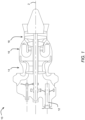
- Fig. 1 illustrates an aircraft engine 10 of a type preferably provided for use in subsonic flight, generally comprising a shaft 12 operatively connectable to a fan or other rotor, such as a helicopter rotor, for propelling ambient air, and in serial flow communication a compressor section 14 for pressurizing ambient air, a combustor 16 in which the compressed air is mixed with fuel and ignited for generating an annular stream of hot combustion gases, and a turbine section 18 for extracting energy from the combustion gases.
- Components of the engine 10 are rotatable about a longitudinal center axis 2 of the engine 10.
- the engine 10 is a turboshaft engine. It is contemplated that the engine 10 could be a different type of engine, such as a rotary engine, a turboprop, or a turbofan engine for example.
- Fig. 2 schematically illustrates an aircraft 20, in this example a helicopter, having a first engine 10', and a second engine 10".
- the engines 10', 10" are operable to provide motive power to the aircraft 20 via conventional transmission systems and controls.
- each of the engines 10', 10" is substantially the same as engine 10 shown in Fig. 1 and described above. Therefore, only the first engine 10' is described in further detail.
- Parts of the second engine 10" that correspond to parts of the first engine 10' are labeled with the same numerals.
- the first engine 10' includes a first bleed air conduit 22 and a second bleed air conduit 24, both of which bleed compressed air from respective parts of the compressor section 14 of the first engine 10'.
- the first bleed air conduit 22 includes a check valve 24' and branches off into supply bleed air conduits 23 downstream of the check valve.
- the second bleed air conduit 24 includes a check valve 24' and a check valve 22'.
- the second bleed air conduit 24 branches off into supply bleed air conduits 25 at one or more locations that are fluidly in between the check valves 24', 24".
- the check valves 24', 24" are pointing toward each other, for purposes explained below.
- the supply bleed air conduits 23, 25 deliver bleed air to various sealing systems of the first engine 10'.
- the particular number and configuration of the sealing systems may be any suitable number and configuration, and is therefore not described in detail.
- the supply bleed air conduits 23 and 25 may also provide bleed air for various other functions of the first engine 10' and/or the aircraft. Examples of such functions include, but are not limited to, cooling of turbines, provision of environmental control of the cabin, operation of air systems, and pressurizing liquid tanks. Any suitable air piping and controls arrangement may be used to provide for each particular combination of the functions provided for by the bleed air from the first and second bleed air conduits 22, 24.
- the first and second bleed air conduits 22, 24 of the first engine 10' fluidly converge / join into a common bleed air conduit 26.
- the common bleed air conduit 26 fluidly connects to a control valve 28.
- the control valve 28 may be any suitable one or more control valves so long as it provides for the functionality described in this document.
- the conduits 22, 23, 24, 25, 26 and valves 22', 24', 24" of the first engine 10' are part of a bleed air system 27 of the first engine 10'.
- the rest of the bleed air system 27 may be conventional and is therefore not shown or described in detail herein.
- the bleed air system 29 of the second engine 10" is similar to the bleed air system 27 of the first engine 10', described above. Therefore, to maintain simplicity of this description, the bleed air system 29 of the second engine 10" is not described in detail. Suffice it to say that parts of the bleed air system 29 of the second engine 10" that correspond to parts of the bleed air system 27 of the first engine 10' are labeled with the same numerals.
- the common bleed air conduit 26 of the second engine 10 fluidly connects to a control valve 28.
- the control valve 28 is operable by a controller of the aircraft 20 to selectively: i) fluidly connect the common bleed air conduit 26 of the first engine 10' to the common bleed air conduit 26 of the second engine 10", by fluidly unblocking the air pressure line that the control valve 28 is in, and ii) fluidly disconnect the common bleed air conduit 26 of the first engine 10' from the common bleed air conduit 26 of the second engine 10", by fluidly blocking the air pressure line that the control valve 28 is in, as illustrated by the internal structure of the control valve 28 schematically shown in Fig. 2 .
- the control valve 28 may be actuated using any suitable actuator of the engines 10', 10" and/or of the aircraft 20.
- Fig. 2 shows a first in-flight, mode of operation of the aircraft 20 during which both engines 10', 10" are “active” and are therefore both providing motive power to the aircraft 20.
- active used with respect to a given engine means that the given engine is providing motive power to the aircraft with which it is used.
- the bleed air system 27 of the first engine 10' and the bleed air system 29 of the second engine 10" are both self-sufficient.
- self-sufficient used with respect to a given bleed air system of a given engine means that the given bleed air system of the given engine provides all of its intended functions for the duration of the time during which it is called upon to provide for the functions.
- a given bleed air system of a given engine is not "self-sufficient" when one or more of the intended functions of the given bleed air system may be unavailable or unstable due to a lack of bleed air pressure and/or bleed air supply rate provided by the corresponding engine to the given bleed air system.
- FIG. 3 shows a second in-flight, cruise, mode of operation of the aircraft 20 during which: i) the first engine 10' is "active” and is therefore providing motive power to the aircraft 20, and ii) the second engine 10" is on "standby” (a.k.a. operating in a standby mode) and is therefore not providing any material amount of motive power to the aircraft 20.
- the bleed air system 27 of the first engine 10' is self-sufficient.
- the bleed air system 29 of the second engine 10 may or may not be self-sufficient in the standby mode.
- control valve 28 may be actuated by a suitable controller of the aircraft 20 to fluidly connect the common bleed air conduit 26 of the first engine 10' to the common bleed air conduit 26 of the second engine 10", to provide for an additional supply of bleed air from the bleed air system 27 of the first engine 10' to the bleed air system 29 of the second engine 10".
- Self-sufficiency of the bleed air system 29 of the second engine 10" may thereby be provided.
- the control valve 28 may be actuated by a suitable controller of the aircraft 20 to fluidly disconnect the common bleed air conduit 26 of the first engine 10' from the common bleed air conduit 26 of the second engine 10", as shown in Fig. 2 .
- the control valve 28 may be actuated by a suitable controller of the aircraft 20 to fluidly connect the common bleed air conduit 26 of the first engine 10' to the common bleed air conduit 26 of the second engine 10".
- the bleed air system 29 of the second engine 10" may thereby provide compressed air to the bleed air system 27 of the first engine 10'. Self-sufficiency of the bleed air system 27 of the first engine 10' may thereby be provided.
- the bleed air systems 27, 29 of the engines 10', 10" and the control valve 28 are part of an air system 30 of the aircraft 20.
- the air system 30 of the aircraft 20 implemented according to the present technology may thereby provide for self-sufficient operation of at least one of the engines 10', 10" in at least some operating conditions of the aircraft 20 in which at least some prior art engine bleed air systems may not be self-sufficient.
- the check valves 24' and 24" are provided in the bleed air conduits 24, downstream of the branching-out bleed air conduits 25.
- this the branching-out bleed air conduits 25 may supply compressed air to at least some subsystems of the respective engines 10', 10".
- Each of the check valves 24' and 24" ensures that when the engine 10', 10" having that check valve 24', 24" is providing compressed air from its bleed air system 27, 29 to the bleed air system 27, 29 of the other engine 10', 10", the compressed air is provided from the air source corresponding to the bleed air conduit 22 of that engine 10', 10".
- the check valves 24' and 24" therefore help ensure uncompromised self-sufficient operation of the subsystems of the one of the engines 10', 10" that may at a given time be providing compressed air to the other one of the engines 10', 10".
- the check valve 24' and/or the check valve 24" may be omitted.
- the rest of the air system 30 that is not shown in the figures of the present application may be conventional and is therefore not described in detail herein. Any suitable controls and any suitable control logic may be used to provide for the functionality of the air system 30, and/or for various timings of actuation of the control valve 28 relative to switches between "active" and “standby” states that may occur with respect to each of the engines 10', 10" during in-flight or ground operations of the aircraft 20.
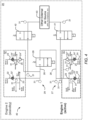
- air system 40 of the aircraft 20 which is an alternative embodiment of the air system 30 is shown.
- the air system 40 is similar to the air system 30, and therefore similar reference numerals have been used for the air system 40.
- a difference of the air system 40 from the air system 30, is that air system 40 includes a control valve 41, a control valve 42, and an external compressed air source 43 such as an auxiliary power unit (APU) and/or an air compressor for example.
- the external compressed air source 43 may be any conventional external compressed air source suitable for each particular embodiment of the engines 10', 10" and the aircraft 20.
- the control valve 41 selectively fluidly connects the external compressed air source 43 to the common bleed air conduit 26 of the first engine 10', via any suitable corresponding air conduits. More particularly, when the first engine 10' is "active", the control valve 41 may be actuated by a suitable controller of the aircraft 20 to fluidly disconnect the external compressed air source 43 from the common bleed air conduit 26 of the first engine 10', and may thereby allow the bleed air system 27 of the first engine 10' to run self-sufficiently.
- control valve 41 When the first engine 10' is on "standby", the control valve 41 may be actuated by a suitable controller of the aircraft 20 to fluidly connect the external compressed air source 43 to the common bleed air conduit 26 of the first engine 10'.
- the control valve 41 may thereby provide "supplemental" compressed air to the bleed air system 27 of the first engine 10' at a supply rate and pressure sufficient to allow the bleed air system 27 of the first engine 10' to provide for all of its intended functions during the "standby" operation of the first engine 10'.
- the control valve 41 via corresponding air conduit(s), may selectively fluidly connect the external compressed air source 43 to a different part of the bleed air system 27 of the first engine 10', so long as the functionality described above is provided.
- the control valve 42 similarly fluidly connects the external compressed air source 43 to the common bleed air conduit 26 of the second engine 10", and is actuated according to a similar control logic to allow the bleed air system 29 of the second engine 10" to provide for all of its intended functions during the "standby" operation of the second engine 10".
- the control valve 28 that fluidly connects the bleed air system 27 of the first engine 10' to the bleed air system 29 of the second engine 10" may be in a position in which it fluidly disconnects the first engine 10' from the second engine 10", to allow for the supplemental compressed air to be provided to either one, or to both, of the engines 10', 10" by the external compressed air source 43.
- control valves 28, 41, 42 may be actuated correspondingly to switch between the various possible supply modes of air described above.
- the bleed air system 27, 29 of one of the engines 10', 10" may receive "supplemental" compressed air from one or both of: i) the bleed air system 27, 29 of another one of the engines 10', 10", and ii) the external compressed air source 43.
- FIG. 5 an air system 50 of the aircraft 20, which is yet another alternative embodiment of the air system 30 is shown.
- the air system 50 is similar to the air system 40, and therefore similar reference numerals have been used for the air system 50.
- a of the air system 50 difference from the air system 40, is that air system 50 does not have a control valve 28 for fluidly connecting the bleed air system 27 of the first engine 10' to the bleed air system 29 of the second engine 10". Operation of the air system 50 is similar to operation of the air system 40 with respect to the external compressed air source 43.
- the air systems 30, 40, 50 may allow to provide "supplemental" compressed air to the bleed air system 27, 29 of one of the engines 10', 10" in at least some cases where that bleed air system 27, 29 is malfunctioning and/or leaking air for example.
- a person skilled in the art will appreciate that while a particular air conduit arrangement is shown in Figs. 1 to 5 , other air conduit arrangements may be used while providing for at least some of the functionality described in this document. While a single external compressed air source 43 is used in the embodiments of Figs. 4 and 5 , multiple different external compressed air sources may be used.
- the example aircraft 20 has two engines 10', 10"
- the present technology may be implemented with respect to more than two engines and/or with respect to other types of engines.
- the present technology provides a method 60 of using, in flight, a source of pressurized air external to an engine of an aircraft 20.
- the source of pressurized air may be one of the engines 10', 10" of the aircraft 20, and in some embodiments, an APU 43 or air compressor 43 of the aircraft 20.
- the method 60 includes a step 61 of operating a given engine 10', 10" of the aircraft 20 during flight.
- the method 60 also includes a step 62 of directing pressurized air from the source of pressurized air external to the given engine 10', 10", to a bleed air system 27, 29 of the given engine 10', 10".
- the given engine 10', 10" to which pressurized air is directed is a first engine 10' of the aircraft 20, the aircraft 20 includes a second engine 10", and the source of pressurized air external to the first engine 10' is a bleed air system 29 of the second engine 10".
- the aircraft 20 is a multi-engine helicopter in which the engines 10', 10" are operatively connected to drive at least one main rotor of the helicopter to provide motive power to / propel the helicopter.
- the directing pressurized air to the bleed air system 27 of the first engine 10' is executed when the first engine 10' is operating on standby.
- the source of the pressurized air is the bleed air system 29 of the second engine 10
- the second engine 10" is active (i.e. providing motive power to the helicopter).
- the given engine 10', 10" to which pressurized air is directed is a second engine 10" of the aircraft 20.
- the source of pressurized air external to the second engine 10" is a bleed air system 27 of the first engine 10'.
- the second engine 10" is on standby while the first engine 10' providing the compressed air is active (i.e. providing motive power to the helicopter).
- the source of pressurized air is a first source of pressurized air (e.g. first engine 10' or second engine 10", depending on which of these engines is active and which is on standby), the aircraft 20 includes a second source of pressurized air (e.g. APU / air compressor 43 of the aircraft 20).
- the second source of pressurized air 43 is external to both the first engine 10' and the second engine 10".
- the method 60 comprises directing pressurized air from the second source of pressurized air 43 to the first engine 10'.
- the method 60 comprises directing pressurized air from the second source of pressurized air 43 to the second engine 10".
- the method 60 comprises directing pressurized air from the second source of pressurized air 43 to both the first engine 10' and the second engine 10".
- the present technology also provides method 70 of operating a bleed air system 27 of a first gas turbine engine 10' of a multi-engine aircraft 20 during flight.
- the method 70 comprises a step 71 of operating the first gas turbine engine 10' of the aircraft 20 during flight in a standby mode, such as an idle or a sub-idle mode that provides either no motive power or at least materially no motive power to the aircraft 20.
- the method 70 comprises a step 71 of operating a second gas turbine engine 10" of the aircraft 20 during flight in an active mode (i.e. providing non-substantially-zero motive power to the aircraft 20).
- the steps 71 and 72 are executed simultaneously.
- the method 70 comprises directing pressurized air from a bleed air system 29 of the second gas turbine engine 10" to a bleed air system 27 of the first gas turbine engine 10'.
- the method 70 further includes a step 73 of operating a source of pressurized air (E.g. APU / air compressor 43, and the like) of the aircraft 20 external to both the first gas turbine engine 10' and the second gas turbine engine 10", and a step of directing pressurized air from the source of pressurized air 43 to at least one of the first gas turbine engine 10' and the second gas turbine engine 10".
- a source of pressurized air E.g. APU / air compressor 43, and the like
- the directing pressurized air from one of the bleed air systems 27, 29 to the other one of the bleed air systems 27, 29 may be executed simultaneously with directing pressurized air from a second source of pressurized air to the one of the bleed air systems 27, 29 that is receiving the supplemental compressed air.
- the second source of pressurized air 43 includes, or is, at least one of: an APU 43 of the aircraft 20, and an air compressor 43 of the aircraft 20.
- the air pressure in the one of the bleed air systems 27, 29 receiving supplemental compressed air may be lower than the pressure of the supplemental compressed air. It is contemplated that any suitable controls and control arrangements may be used to provide for this pressure differential, where required. While two engines 10', 10" of an aircraft 20 are described, it is contemplated that the present technology could be implemented with regard to a larger number of engines of an aircraft to provide supplemental compressed air from one or more of the engines or other compressed air source(s), to one or more other ones of the engines.
- the air systems 30, 40, 50 described above may help improve switching between active modes of operation and the "sub-idle" modes of operation of one or more engines of a multi-engine aircraft.
- the air systems 30, 40, 50 further comprise one or more pressure wave dampers 31 in air communication with one or more of the air pressure lines / conduits 22-26.
- a non-limiting example of one of the pressure wave dampers 31 is shown in detail in Fig. 5 .
- pressure wave damper includes all devices that may in the present art be referred to as a pressure wave arrestor, pressure wave suppressor, pressure wave attenuator, and the like, and their equivalents including one or more branch pipes configured to filter out one or more frequencies associated with the unwanted pressure waves.
- the pressure wave damper(s) 31 may absorb and/or dampen and/or attenuate at least some of the pressure waves / pulses / air pressure fluctuations / pulsations in the air pressure line(s) / conduit(s) 22-26 that may be generated during operation of the air systems 30, 40, 50, such as through executing the various methods 60, 70 described above for example.
- this may help reduce a likelihood of standing wave resonances in the air systems 30, 40, 50, and may help prolong an expected life cycle of the air systems 30, 40, 50.
- at least some of the pressure wave dampers 31 are made large enough to act as resonators during steady state engine operation, thereby helping dissipate transient/surge pressure within the respective line(s) to which it/they are connected.
- the neck dimensions (length and diameter) of a given pressure wave damper 31 may be tuned to resonate with the accompanying volume of the given pressure wave damper 31 at the most prevalent excitation frequency and/or an Eigen frequency of the corresponding air pressure line, to dissipate energy that may be imparted to the air pressure line, for example as a result of a control valve operation and/or a switchover of an engine from a standby mode to an active mode and/or vice versa, prior to distressing the air pressure line.
- the pressure wave damper(s) 31 may be fluidly connected into the air systems 30, 40, 50 at locations proximate to one or more of the valves, for example valves 22', 24', 24", 28, 41, 42, of the air systems 30, 40, 50. Also as shown, in some embodiments, the pressure wave damper(s) 31 may be fluidly connected into the air systems 30, 40, 50 at locations each of which may have been determined to correspond to an air pressure maxima, and/or a maximum of a pressure wave inside the corresponding duct(s), pipe(s) or other air conduit(s), in the respective air system 30, 40, 50. Such positioning may help further reduce a likelihood of, and in some embodiments and applications prevent, standing wave resonances in the air systems 30, 40, 50, and may further help prolong life of the air systems 30, 40, 50.
- the air pressure maximums may be determined at one or more switchover conditions of the air systems 30, 40, 50, as described above (a.k.a. transient operation), during which the air systems 30, 40, 50 may switch, for example: a) from supplying one of the engines 10', 10" with supplemental compressed air to supplying another one of the engines 10', 10" with supplemental compressed air, or b) from not supplying any supplemental compressed air to any of the engines 10', 10" to supplying supplemental compressed air to at least one of the engines 10', 10".
- the air pressure maximum, and/or the maximum of a pressure wave may be calculated (e.g. by modeling) as a maximum air pressure in the air pressure line when the control valve switches between one of: i) from fluidly blocking the air pressure line to fluidly unblocking the air pressure line, and ii) from fluidly unblocking the air pressure line to fluidly blocking the air pressure line.
- one or more of the pressure wave damper 31 may be a Helmholtz resonator.
- one or more of the pressure wave damper 31 may include a membrane / diaphragm that is fluidly and/or mechanically pressurized to enhance a frequency response of the respective air systems 30, 40, 50.
- one or more of the pressure wave damper 31 may include a resonator volume that absorbs and/or attenuates and/or dissipates shockwaves and/or pressure oscillations and/or other aerodynamic instabilities.
- the resonator volume(s) may be spherical, cylindrical, or a 3D complex shape for example, and may be made sufficiently large to dissipate transient / surge pressure within the respective air lines, to assist in mitigating stresses during the transient operations of the air systems 30, 40, 50.
- one or more of the pressure wave dampers 31 may include a neck 32 (numbered in Fig. 2 only, to preserve clarity of the figures) that fluidly connects the resonator volume(s) to the respective air lines.
- the resonator neck dimensions including a length and diameter thereof, may be selected to resonate with the corresponding resonator volume(s) at a prevalent excitation frequency and/or at an Eigen frequency of the corresponding air line. In at least some cases, such dimensioning may help reduce stresses experienced by the respective air systems 30, 40, 50 during steady state operation.
- the Helmohltz resonator may have an opening having an opening area (A), a neck with a length (L), and a volume (V).
Landscapes
- Engineering & Computer Science (AREA)
- Chemical & Material Sciences (AREA)
- Combustion & Propulsion (AREA)
- Mechanical Engineering (AREA)
- General Engineering & Computer Science (AREA)
- Physics & Mathematics (AREA)
- Fluid Mechanics (AREA)
- Control Of Turbines (AREA)
Description
- The application relates generally to air systems of multi-engine aircraft.
- Helicopters may have two or more engines powering a main rotor via a common reduction gearbox, and each of the engines is typically sized such that the power of each engine is greater than what is required by the helicopter in cruise. Improving operating fuel efficiencies of such multi-engine systems is desirable.
US 2018/022465 discloses a multi-engine aircraft andUS 2019/093565 discloses a resonator. - In an aspect, there is provided a multi-engine aircraft according to
claim 1. - In optional embodiments, the first engine and/or the second engine is configured for standby operation in-flight.
- In optional embodiments, the air pressure line includes a control valve operable to fluidly block and fluidly unblock the air pressure line.
- In optional embodiments, the pressure wave damper connects to the air pressure line at a location proximate to the control valve, and neck dimensions of the pressure wave damper are tuned to resonate with a volume of the pressure wave damper at a most prevalent excitation frequency and/or an Eigen frequency of the air pressure line, to dissipate energy imparted to the air pressure line via operation of the control valve prior to distressing the air pressure line.
- In optional embodiments, the location corresponds to a pressure wave maximum experienced by the air pressure line during operation of the aircraft.
- In optional embodiments, the pressure wave maximum is calculated as a maximum air pressure in the air pressure line when the control valve switches between one of: i) from fluidly blocking the air pressure line to fluidly unblocking the air pressure line, and ii) from fluidly unblocking the air pressure line to fluidly blocking the air pressure line.
- In optional embodiments, the pressure wave damper comprises a neck and a resonator volume, the neck fluidly connects the resonator volume to the air pressure line, and dimensions of the neck and the resonator volume are configured to attenuate a frequency of a pressure wave in the air pressure line.
- In optional embodiments, at least one of the first and second engines is configured to operate in a sub-idle mode while another one of the first and second engines is operating in an active mode.
- In optional embodiments, each of the first and the second engine is operable in any one of a standby mode and an active mode, and the source of pressurized air is: a) the bleed air system of the second engine when the first engine is operating in the standby mode, b) the bleed air system of the first engine when the second engine is operating in the standby mode.
- In optional embodiments, the aircraft further includes a second source of pressurized air that is external to both the first and the second engine, the second source of pressurized air being selectively fluidly connectable simultaneously to both first and the second engine, and the pressure wave damper is a plurality of pressure wave dampers that includes a first pressure wave damper disposed fluidly between the second source of pressurized air and the bleed air system of the first engine, and a second pressure wave damper disposed fluidly between the second source of pressurized air and the bleed air system of the second engine.
- In optional embodiments, the second source of pressurized air is an auxiliary power unit of the aircraft.
- In optional embodiments, the second source of pressurized air is an air compressor of the aircraft.
- Reference is now made to the accompanying figures in which:
-
Fig. 1 is a schematic cross sectional view of a gas turbine engine; -
Fig. 2 is a schematic of two gas turbine engines and of an air system of an aircraft, with both of the engines being active; -
Fig. 3 is a schematic of the two gas turbine engines and of the air system ofFig. 2 , with one of the engines being active and another one of the engines being on standby; -
Fig. 4 is a schematic of two gas turbine engines and of the air system of the aircraft ofFig. 2 , the air system being implement according to another embodiment; -
Fig. 5 is a schematic of two gas turbine engines and of the air system of the aircraft ofFig. 2 , the air system being implement according to yet another embodiment; -
Fig. 6 is a schematic logic diagram showing a method implemented according to an embodiment of the present technology; and -
Fig. 7 is a schematic logic diagram showing a method implemented according to another embodiment of the present technology. - Bleed air produced by a gas turbine engine of an aircraft is compressed air from the compressor stage that is used for various functions of that engine (such as cooling of turbines and to help seal bearing cavities, for example). Bleed air may also be used for aircraft functions (such as engine starting, cabin pressure, air systems, pressurizing liquid tanks, etc.). Engine bleed air can be derived from the high pressure or the low pressure compressor stage, depending on the air pressure requirements and the engine operating condition.
- In at least some multi-engine aircraft, such as helicopters, prior art bleed systems may not be capable of supplying an adequate flowrate and/or pressure of bleed air in some operating conditions, such as when a gas turbine engine providing the bleed air is operating in a standby mode. For the purposes of this document, the terms "standby" and "sub-idle" are used with respect to a given engine to mean that the given engine is operating but is providing materially no motive power to the aircraft with which it is used, with the "sub-idle" operation being a particular type of standby operation according to the present technology as described in this document.
- The present technology has been developed in view of this finding, and provides for a secondary compressed air system may provide compressed air to one or more of an aircraft's engines while the engine(s) is/are in a standby or a sub-idle mode. With the development of the present compressed air system technology, it has been further discovered by the developers that at least when applied to some aircraft, the compressed air system may have plumbing lengths that are sufficiently long to be potentially affected by standing wave resonances, pressure pulsations, vibrations, noise and other stresses. It has been found that such additional stresses may pose a risk in at least some cases of premature deterioration of one or more of the compressed air system components.
-
Fig. 1 illustrates anaircraft engine 10 of a type preferably provided for use in subsonic flight, generally comprising ashaft 12 operatively connectable to a fan or other rotor, such as a helicopter rotor, for propelling ambient air, and in serial flow communication acompressor section 14 for pressurizing ambient air, acombustor 16 in which the compressed air is mixed with fuel and ignited for generating an annular stream of hot combustion gases, and aturbine section 18 for extracting energy from the combustion gases. Components of theengine 10 are rotatable about alongitudinal center axis 2 of theengine 10. In the present embodiment, theengine 10 is a turboshaft engine. It is contemplated that theengine 10 could be a different type of engine, such as a rotary engine, a turboprop, or a turbofan engine for example. -
Fig. 2 schematically illustrates anaircraft 20, in this example a helicopter, having a first engine 10', and asecond engine 10". Theengines 10', 10" are operable to provide motive power to theaircraft 20 via conventional transmission systems and controls. For simplicity, only the nonconventional aspects of the present technology are described in detail in this document. In this embodiment, each of theengines 10', 10" is substantially the same asengine 10 shown inFig. 1 and described above. Therefore, only the first engine 10' is described in further detail. Parts of thesecond engine 10" that correspond to parts of the first engine 10' are labeled with the same numerals. - As shown schematically in
Fig. 2 , the first engine 10' includes a first bleedair conduit 22 and a second bleedair conduit 24, both of which bleed compressed air from respective parts of thecompressor section 14 of the first engine 10'. In the present embodiment, the first bleedair conduit 22 includes a check valve 24' and branches off into supply bleedair conduits 23 downstream of the check valve. In this embodiment, the second bleedair conduit 24 includes a check valve 24' and a check valve 22'. The second bleedair conduit 24 branches off into supply bleedair conduits 25 at one or more locations that are fluidly in between thecheck valves 24', 24". As shown, thecheck valves 24', 24" are pointing toward each other, for purposes explained below. - The supply bleed
air conduits air conduits air conduits - Still referring to
Fig. 2 , the first and second bleedair conduits air conduit 26. The common bleedair conduit 26 fluidly connects to acontrol valve 28. Thecontrol valve 28 may be any suitable one or more control valves so long as it provides for the functionality described in this document. Theconduits valves 22', 24', 24" of the first engine 10' are part of ableed air system 27 of the first engine 10'. The rest of thebleed air system 27 may be conventional and is therefore not shown or described in detail herein. - As shown in
Fig. 2 , in the present embodiment, thebleed air system 29 of thesecond engine 10" is similar to thebleed air system 27 of the first engine 10', described above. Therefore, to maintain simplicity of this description, thebleed air system 29 of thesecond engine 10" is not described in detail. Suffice it to say that parts of thebleed air system 29 of thesecond engine 10" that correspond to parts of thebleed air system 27 of the first engine 10' are labeled with the same numerals. - As shown in
Fig. 2 , the commonbleed air conduit 26 of thesecond engine 10", similar to the commonbleed air conduit 26 of the first engine 10', fluidly connects to acontrol valve 28. Thecontrol valve 28 is operable by a controller of theaircraft 20 to selectively: i) fluidly connect the commonbleed air conduit 26 of the first engine 10' to the commonbleed air conduit 26 of thesecond engine 10", by fluidly unblocking the air pressure line that thecontrol valve 28 is in, and ii) fluidly disconnect the commonbleed air conduit 26 of the first engine 10' from the commonbleed air conduit 26 of thesecond engine 10", by fluidly blocking the air pressure line that thecontrol valve 28 is in, as illustrated by the internal structure of thecontrol valve 28 schematically shown inFig. 2 . Thecontrol valve 28 may be actuated using any suitable actuator of theengines 10', 10" and/or of theaircraft 20. -
Fig. 2 shows a first in-flight, mode of operation of theaircraft 20 during which bothengines 10', 10" are "active" and are therefore both providing motive power to theaircraft 20. For the purposes of this document, the term "active" used with respect to a given engine means that the given engine is providing motive power to the aircraft with which it is used. - In this operating condition, the
bleed air system 27 of the first engine 10' and thebleed air system 29 of thesecond engine 10" are both self-sufficient. For the purposes of this document, the term "self-sufficient" used with respect to a given bleed air system of a given engine means that the given bleed air system of the given engine provides all of its intended functions for the duration of the time during which it is called upon to provide for the functions. A given bleed air system of a given engine is not "self-sufficient" when one or more of the intended functions of the given bleed air system may be unavailable or unstable due to a lack of bleed air pressure and/or bleed air supply rate provided by the corresponding engine to the given bleed air system. - Reference is now made to
Fig. 3 , which shows a second in-flight, cruise, mode of operation of theaircraft 20 during which: i) the first engine 10' is "active" and is therefore providing motive power to theaircraft 20, and ii) thesecond engine 10" is on "standby" (a.k.a. operating in a standby mode) and is therefore not providing any material amount of motive power to theaircraft 20. In this operating mode (i.e. in the second in-flight mode of operation), thebleed air system 27 of the first engine 10' is self-sufficient. On the other hand, depending on each particular embodiment of theengines 10', 10" and/or theaircraft 20 and/or on the characteristics of the particular "standby" operation of thesecond engine 10", thebleed air system 29 of thesecond engine 10" may or may not be self-sufficient in the standby mode. - For this reason, during the second in-flight mode of operation of the
aircraft 20, thecontrol valve 28 may be actuated by a suitable controller of theaircraft 20 to fluidly connect the commonbleed air conduit 26 of the first engine 10' to the commonbleed air conduit 26 of thesecond engine 10", to provide for an additional supply of bleed air from thebleed air system 27 of the first engine 10' to thebleed air system 29 of thesecond engine 10". Self-sufficiency of thebleed air system 29 of thesecond engine 10" may thereby be provided. After thesecond engine 10" is brought into an "active" state while the first engine 10' is in an "active" state, thecontrol valve 28 may be actuated by a suitable controller of theaircraft 20 to fluidly disconnect the commonbleed air conduit 26 of the first engine 10' from the commonbleed air conduit 26 of thesecond engine 10", as shown inFig. 2 . After the first engine 10' is put into a standby mode or a sub-idle mode while thesecond engine 10" is in an "active" mode, thecontrol valve 28 may be actuated by a suitable controller of theaircraft 20 to fluidly connect the commonbleed air conduit 26 of the first engine 10' to the commonbleed air conduit 26 of thesecond engine 10". Thebleed air system 29 of thesecond engine 10" may thereby provide compressed air to thebleed air system 27 of the first engine 10'. Self-sufficiency of thebleed air system 27 of the first engine 10' may thereby be provided. - The
bleed air systems engines 10', 10" and thecontrol valve 28 are part of anair system 30 of theaircraft 20. As described above, theair system 30 of theaircraft 20 implemented according to the present technology may thereby provide for self-sufficient operation of at least one of theengines 10', 10" in at least some operating conditions of theaircraft 20 in which at least some prior art engine bleed air systems may not be self-sufficient. - Further, as shown in
Figs. 2 and3 for example, in the present embodiment, thecheck valves 24' and 24" are provided in thebleed air conduits 24, downstream of the branching-outbleed air conduits 25. In this embodiment, this the branching-outbleed air conduits 25 may supply compressed air to at least some subsystems of therespective engines 10', 10". Each of thecheck valves 24' and 24" ensures that when theengine 10', 10" having thatcheck valve 24', 24" is providing compressed air from itsbleed air system bleed air system other engine 10', 10", the compressed air is provided from the air source corresponding to thebleed air conduit 22 of thatengine 10', 10". Thecheck valves 24' and 24" therefore help ensure uncompromised self-sufficient operation of the subsystems of the one of theengines 10', 10" that may at a given time be providing compressed air to the other one of theengines 10', 10". In some embodiments, the check valve 24' and/or thecheck valve 24" may be omitted. - The rest of the
air system 30 that is not shown in the figures of the present application may be conventional and is therefore not described in detail herein. Any suitable controls and any suitable control logic may be used to provide for the functionality of theair system 30, and/or for various timings of actuation of thecontrol valve 28 relative to switches between "active" and "standby" states that may occur with respect to each of theengines 10', 10" during in-flight or ground operations of theaircraft 20. - Referring now to
Fig. 4 , anair system 40 of theaircraft 20, which is an alternative embodiment of theair system 30 is shown. Theair system 40 is similar to theair system 30, and therefore similar reference numerals have been used for theair system 40. A difference of theair system 40 from theair system 30, is thatair system 40 includes acontrol valve 41, acontrol valve 42, and an externalcompressed air source 43 such as an auxiliary power unit (APU) and/or an air compressor for example. The externalcompressed air source 43 may be any conventional external compressed air source suitable for each particular embodiment of theengines 10', 10" and theaircraft 20. - The
control valve 41 selectively fluidly connects the externalcompressed air source 43 to the commonbleed air conduit 26 of the first engine 10', via any suitable corresponding air conduits. More particularly, when the first engine 10' is "active", thecontrol valve 41 may be actuated by a suitable controller of theaircraft 20 to fluidly disconnect the externalcompressed air source 43 from the commonbleed air conduit 26 of the first engine 10', and may thereby allow thebleed air system 27 of the first engine 10' to run self-sufficiently. - When the first engine 10' is on "standby", the
control valve 41 may be actuated by a suitable controller of theaircraft 20 to fluidly connect the externalcompressed air source 43 to the commonbleed air conduit 26 of the first engine 10'. Thecontrol valve 41 may thereby provide "supplemental" compressed air to thebleed air system 27 of the first engine 10' at a supply rate and pressure sufficient to allow thebleed air system 27 of the first engine 10' to provide for all of its intended functions during the "standby" operation of the first engine 10'. Thecontrol valve 41, via corresponding air conduit(s), may selectively fluidly connect the externalcompressed air source 43 to a different part of thebleed air system 27 of the first engine 10', so long as the functionality described above is provided. - The
control valve 42 similarly fluidly connects the externalcompressed air source 43 to the commonbleed air conduit 26 of thesecond engine 10", and is actuated according to a similar control logic to allow thebleed air system 29 of thesecond engine 10" to provide for all of its intended functions during the "standby" operation of thesecond engine 10". As shown, thecontrol valve 28 that fluidly connects thebleed air system 27 of the first engine 10' to thebleed air system 29 of thesecond engine 10" may be in a position in which it fluidly disconnects the first engine 10' from thesecond engine 10", to allow for the supplemental compressed air to be provided to either one, or to both, of theengines 10', 10" by the externalcompressed air source 43. In some embodiments, thecontrol valves bleed air system engines 10', 10" may receive "supplemental" compressed air from one or both of: i) thebleed air system engines 10', 10", and ii) the externalcompressed air source 43. - Referring now to
Fig. 5 , anair system 50 of theaircraft 20, which is yet another alternative embodiment of theair system 30 is shown. Theair system 50 is similar to theair system 40, and therefore similar reference numerals have been used for theair system 50. A of theair system 50 difference from theair system 40, is thatair system 50 does not have acontrol valve 28 for fluidly connecting thebleed air system 27 of the first engine 10' to thebleed air system 29 of thesecond engine 10". Operation of theair system 50 is similar to operation of theair system 40 with respect to the externalcompressed air source 43. - In at least some embodiments and applications, the
air systems bleed air system engines 10', 10" in at least some cases where that bleedair system Figs. 1 to 5 , other air conduit arrangements may be used while providing for at least some of the functionality described in this document. While a single externalcompressed air source 43 is used in the embodiments ofFigs. 4 and5 , multiple different external compressed air sources may be used. Likewise, while theexample aircraft 20 has twoengines 10', 10", the present technology may be implemented with respect to more than two engines and/or with respect to other types of engines. - With the above systems in mind, the present technology provides a
method 60 of using, in flight, a source of pressurized air external to an engine of anaircraft 20. As seen above, in some embodiments and operating conditions, the source of pressurized air may be one of theengines 10', 10" of theaircraft 20, and in some embodiments, anAPU 43 orair compressor 43 of theaircraft 20. In some embodiments, themethod 60 includes astep 61 of operating a givenengine 10', 10" of theaircraft 20 during flight. In some embodiments, themethod 60 also includes astep 62 of directing pressurized air from the source of pressurized air external to the givenengine 10', 10", to ableed air system engine 10', 10". - In some embodiments, the given
engine 10', 10" to which pressurized air is directed is a first engine 10' of theaircraft 20, theaircraft 20 includes asecond engine 10", and the source of pressurized air external to the first engine 10' is ableed air system 29 of thesecond engine 10". As seen above, in some embodiments, theaircraft 20 is a multi-engine helicopter in which theengines 10', 10" are operatively connected to drive at least one main rotor of the helicopter to provide motive power to / propel the helicopter. - As seen above, in some embodiments, the directing pressurized air to the
bleed air system 27 of the first engine 10' is executed when the first engine 10' is operating on standby. In embodiments in which the source of the pressurized air is thebleed air system 29 of thesecond engine 10", thesecond engine 10" is active (i.e. providing motive power to the helicopter). Similarly, in some operating conditions during flight, the givenengine 10', 10" to which pressurized air is directed is asecond engine 10" of theaircraft 20. In some such cases, the source of pressurized air external to thesecond engine 10" is ableed air system 27 of the first engine 10'. In some such cases, thesecond engine 10" is on standby while the first engine 10' providing the compressed air is active (i.e. providing motive power to the helicopter). - As seen above, in some embodiments, the source of pressurized air is a first source of pressurized air (e.g. first engine 10' or
second engine 10", depending on which of these engines is active and which is on standby), theaircraft 20 includes a second source of pressurized air (e.g. APU /air compressor 43 of the aircraft 20). In some such embodiments, the second source ofpressurized air 43 is external to both the first engine 10' and thesecond engine 10". In some such embodiments and in some flight conditions, themethod 60 comprises directing pressurized air from the second source ofpressurized air 43 to the first engine 10'. In some such embodiments and in some flight conditions, themethod 60 comprises directing pressurized air from the second source ofpressurized air 43 to thesecond engine 10". Further in some such embodiments and in some flight conditions, themethod 60 comprises directing pressurized air from the second source ofpressurized air 43 to both the first engine 10' and thesecond engine 10". - Further with the structure of the
aircraft 20 described above, the present technology also providesmethod 70 of operating ableed air system 27 of a first gas turbine engine 10' of amulti-engine aircraft 20 during flight. In some embodiments, themethod 70 comprises astep 71 of operating the first gas turbine engine 10' of theaircraft 20 during flight in a standby mode, such as an idle or a sub-idle mode that provides either no motive power or at least materially no motive power to theaircraft 20. In some embodiments, themethod 70 comprises astep 71 of operating a secondgas turbine engine 10" of theaircraft 20 during flight in an active mode (i.e. providing non-substantially-zero motive power to the aircraft 20). - In some cases, the
steps method 70 comprises directing pressurized air from ableed air system 29 of the secondgas turbine engine 10" to ableed air system 27 of the first gas turbine engine 10'. - In some cases, the
method 70 further includes astep 73 of operating a source of pressurized air (E.g. APU /air compressor 43, and the like) of theaircraft 20 external to both the first gas turbine engine 10' and the secondgas turbine engine 10", and a step of directing pressurized air from the source ofpressurized air 43 to at least one of the first gas turbine engine 10' and the secondgas turbine engine 10". - In some cases, the directing pressurized air from one of the
bleed air systems bleed air systems 27, 29 (depending on which one of thebleed air systems bleed air systems pressurized air 43 includes, or is, at least one of: anAPU 43 of theaircraft 20, and anair compressor 43 of theaircraft 20. - In some such cases, the air pressure in the one of the
bleed air systems engines 10', 10" of anaircraft 20 are described, it is contemplated that the present technology could be implemented with regard to a larger number of engines of an aircraft to provide supplemental compressed air from one or more of the engines or other compressed air source(s), to one or more other ones of the engines. - The
air systems Figs. 2 to 5 , theair systems pressure wave dampers 31 in air communication with one or more of the air pressure lines / conduits 22-26. A non-limiting example of one of thepressure wave dampers 31 is shown in detail inFig. 5 . The term "pressure wave damper" as used herein includes all devices that may in the present art be referred to as a pressure wave arrestor, pressure wave suppressor, pressure wave attenuator, and the like, and their equivalents including one or more branch pipes configured to filter out one or more frequencies associated with the unwanted pressure waves. The pressure wave damper(s) 31 may absorb and/or dampen and/or attenuate at least some of the pressure waves / pulses / air pressure fluctuations / pulsations in the air pressure line(s) / conduit(s) 22-26 that may be generated during operation of theair systems various methods - In at least some cases, like steady state operation, this may help reduce a likelihood of standing wave resonances in the
air systems air systems pressure wave dampers 31 are made large enough to act as resonators during steady state engine operation, thereby helping dissipate transient/surge pressure within the respective line(s) to which it/they are connected. For example, for effectiveness during a steady state operation, the neck dimensions (length and diameter) of a givenpressure wave damper 31 may be tuned to resonate with the accompanying volume of the givenpressure wave damper 31 at the most prevalent excitation frequency and/or an Eigen frequency of the corresponding air pressure line, to dissipate energy that may be imparted to the air pressure line, for example as a result of a control valve operation and/or a switchover of an engine from a standby mode to an active mode and/or vice versa, prior to distressing the air pressure line. - As shown, in some embodiments, the pressure wave damper(s) 31 may be fluidly connected into the
air systems example valves 22', 24', 24", 28, 41, 42, of theair systems air systems respective air system air systems air systems - More particularly, the air pressure maximums may be determined at one or more switchover conditions of the
air systems air systems engines 10', 10" with supplemental compressed air to supplying another one of theengines 10', 10" with supplemental compressed air, or b) from not supplying any supplemental compressed air to any of theengines 10', 10" to supplying supplemental compressed air to at least one of theengines 10', 10". More particularly, for a given air pressure line having a control valve, such as one or more of thecontrol valves - In some embodiments, one or more of the
pressure wave damper 31 may be a Helmholtz resonator. In some embodiments, one or more of thepressure wave damper 31 may include a membrane / diaphragm that is fluidly and/or mechanically pressurized to enhance a frequency response of therespective air systems pressure wave damper 31 may include a resonator volume that absorbs and/or attenuates and/or dissipates shockwaves and/or pressure oscillations and/or other aerodynamic instabilities. In some such embodiments, the resonator volume(s) may be spherical, cylindrical, or a 3D complex shape for example, and may be made sufficiently large to dissipate transient / surge pressure within the respective air lines, to assist in mitigating stresses during the transient operations of theair systems - Also, in some embodiments, one or more of the
pressure wave dampers 31 may include a neck 32 (numbered inFig. 2 only, to preserve clarity of the figures) that fluidly connects the resonator volume(s) to the respective air lines. In some such embodiments, the resonator neck dimensions, including a length and diameter thereof, may be selected to resonate with the corresponding resonator volume(s) at a prevalent excitation frequency and/or at an Eigen frequency of the corresponding air line. In at least some cases, such dimensioning may help reduce stresses experienced by therespective air systems - The above description is meant to be exemplary only, and one skilled in the art will recognize that changes may be made to the embodiments described without departing from the scope of the disclosed technology.
Claims (12)
- A multi-engine aircraft (20), comprising:first and second gas turbine engines (10', 10") for providing motive power to the aircraft (20), each of the first and second engines comprising an air system (27, 29);an air pressure line (26) extending between and fluidly connecting the air systems (27, 29) of the first and second engines (10', 10"); and, characterised bya pressure wave damper (31) communicating with the air pressure line (26) extending between the first and second engines (10', 10"), andone or more pressure wave dampers (31) communicating with one or more air pressure lines (26) that are part of the air systems (27, 29) of the first and second engines (10', 10"), each of the one or more pressure wave dampers (31) being disposed at a location corresponding to a pressure wave maximum of each air pressure line (26) of the one or more air pressure lines (26) corresponding to that pressure wave damper (31).
- The multi-engine aircraft of claim 1, wherein the first engine (10') and/or the second engine (10") is configured for standby operation in-flight.
- The multi-engine aircraft of claim 1 or 2, wherein the air pressure line (26) includes a control valve (28) operable to fluidly block and fluidly unblock the air pressure line (26).
- The multi-engine aircraft of claim 3, wherein the pressure wave damper (31) connects to the air pressure line (26) at a location proximate to the control valve (28), and neck dimensions of the pressure wave damper (31) are tuned to resonate with a volume of the pressure wave damper (31) at a most prevalent excitation frequency and/or an Eigen frequency of the air pressure line (26), to dissipate energy imparted to the air pressure line (26) via operation of the control valve (28) prior to distressing the air pressure line (26).
- The multi-engine aircraft of claim 4, wherein the location proximate to the control valve (28) corresponds to a pressure wave maximum experienced by the air pressure line (26) during operation of the aircraft (20).
- The multi-engine aircraft of claim 5, wherein the pressure wave maximum is calculated as a maximum air pressure in the air pressure line (26) when the control valve (28) switches between one of: i) from fluidly blocking the air pressure line (26) to fluidly unblocking the air pressure line (26), and ii) from fluidly unblocking the air pressure line (26) to fluidly blocking the air pressure line (26).
- The multi-engine aircraft of any one of claims 1 to 6, wherein the pressure wave damper (31) comprises a neck (32) and a resonator volume, the neck (32) fluidly connects the resonator volume to the air pressure line (26), and dimensions of the neck (32) and the resonator volume are configured to attenuate a frequency of a pressure wave in the air pressure line (26).
- The multi-engine aircraft of any one of claims 1 to 7, comprising:
a source of pressurized air (27, 29, 43) that is external to the first gas turbine engine (10')and/or the second gas turbine engine (10"), the source of pressurized air (27, 29, 43) being selectively fluidly connectable to the air system (27, 29) of the at least one of the first and the second gas turbine engines (10', 10") via a plurality of air conduits. - The multi-engine aircraft of claim 8, wherein at least one of the first and second gas turbine engines (10', 10") is configured to operate in a sub-idle mode while another one of the first and second gas turbine engines (10', 10") is operating in an active mode.
- The multi-engine aircraft of claim 9, wherein each of the first and the second gas turbine engines (10', 10") is operable in any one of a standby mode and an active mode, and the source of pressurized air (27, 29, 43) is: a) the air system of the second engine (29) when the first engine (10') is operating in the standby mode, b) the air system of the first engine (27) when the second engine (10") is operating in the standby mode.
- The multi-engine aircraft of claim 8, 9 or 10, further comprising a second source of pressurized air (43) that is external to both the first and the second engine (10', 10"), the second source of pressurized air (43) being selectively fluidly connectable simultaneously to both first and the second engine (10', 10"), and the one or more pressure wave dampers (31) includes a first pressure wave damper (31) disposed fluidly between the second source of pressurized air (43) and the bleed air system of the first engine (27), and a second pressure wave damper (31) disposed fluidly between the second source of pressurized air (43) and the bleed air system of the second engine (29).
- The multi-engine aircraft of claim 11, wherein the second source of pressurized air (43) is an auxiliary power unit of the aircraft (20) or an air compressor of the aircraft (20).
Applications Claiming Priority (2)
| Application Number | Priority Date | Filing Date | Title |
|---|---|---|---|
| US201962855131P | 2019-05-31 | 2019-05-31 | |
| US16/672,977 US11859536B2 (en) | 2019-05-31 | 2019-11-04 | Air system of multi-engine aircraft |
Publications (2)
| Publication Number | Publication Date |
|---|---|
| EP3798423A1 EP3798423A1 (en) | 2021-03-31 |
| EP3798423B1 true EP3798423B1 (en) | 2023-10-11 |
Family
ID=73550633
Family Applications (1)
| Application Number | Title | Priority Date | Filing Date |
|---|---|---|---|
| EP20175924.8A Active EP3798423B1 (en) | 2019-05-31 | 2020-05-21 | Air system of multi-engine aircraft |
Country Status (3)
| Country | Link |
|---|---|
| US (1) | US11859536B2 (en) |
| EP (1) | EP3798423B1 (en) |
| CA (1) | CA3078124A1 (en) |
Families Citing this family (1)
| Publication number | Priority date | Publication date | Assignee | Title |
|---|---|---|---|---|
| FR3109174B1 (en) * | 2020-04-10 | 2022-04-22 | Safran Aircraft Engines | Acoustically optimized channeled discharge duct grille |
Family Cites Families (12)
| Publication number | Priority date | Publication date | Assignee | Title |
|---|---|---|---|---|
| US3192848A (en) | 1962-06-21 | 1965-07-06 | Garrett Corp | Air flow control system |
| FR2705733B1 (en) * | 1993-05-25 | 1995-06-30 | Snecma | Device for depressurizing the lubrication chambers surrounding the bearings of a turbomachine. |
| US6609489B1 (en) * | 2002-05-07 | 2003-08-26 | General Motors Corporation | Apparatus and method for reducing engine noise |
| US7121078B2 (en) | 2003-01-28 | 2006-10-17 | General Electric Company | Methods and apparatus for operating gas turbine engines |
| US8381871B1 (en) | 2011-09-28 | 2013-02-26 | Visteon Global Technologies, Inc. | Compact low frequency resonator |
| FR3019219B1 (en) * | 2014-03-27 | 2016-03-18 | Turbomeca | ARCHITECTURE OF A PROPULSIVE SYSTEM OF A MULTI-ENGINE HELICOPTER AND CORRESPONDING HELICOPTER |
| US9879611B2 (en) * | 2014-07-22 | 2018-01-30 | United Technologies Corporation | Bleed valve resonance augmentations |
| EP3273006B1 (en) | 2016-07-21 | 2019-07-03 | United Technologies Corporation | Alternating starter use during multi-engine motoring |
| US10760484B2 (en) * | 2016-09-16 | 2020-09-01 | Pratt & Whitney Canada Corp. | Multi-engine aircraft power plant with heat recuperation |
| US10167780B2 (en) | 2017-05-25 | 2019-01-01 | Pratt & Whitney Canada Corp. | Tunable resonator |
| JP2019143478A (en) * | 2018-02-15 | 2019-08-29 | 株式会社Roki | Noise suppressor |
| US11015523B2 (en) * | 2018-06-05 | 2021-05-25 | Raytheon Technologies Corporation | Turbofan with bleed supercharged auxiliary engine |
-
2019
- 2019-11-04 US US16/672,977 patent/US11859536B2/en active Active
-
2020
- 2020-04-09 CA CA3078124A patent/CA3078124A1/en active Pending
- 2020-05-21 EP EP20175924.8A patent/EP3798423B1/en active Active
Also Published As
| Publication number | Publication date |
|---|---|
| CA3078124A1 (en) | 2020-11-30 |
| US11859536B2 (en) | 2024-01-02 |
| EP3798423A1 (en) | 2021-03-31 |
| US20200378317A1 (en) | 2020-12-03 |
Similar Documents
| Publication | Publication Date | Title |
|---|---|---|
| US8024935B2 (en) | Flush inlet scoop design for aircraft bleed air system | |
| EP2472081B1 (en) | Variable cycle gas turbine engine | |
| JP2013139796A (en) | Compact high-pressure exhaust muffling device | |
| US20060075754A1 (en) | Aeroengine oil tank fire protection system | |
| EP3744636B1 (en) | Air system of multi-engine aircraft | |
| US11725595B2 (en) | Control logic for gas turbine engine fuel economy | |
| CA2892057C (en) | Integrated actuator, gas turbine engine and corresponding operating method | |
| US11485508B2 (en) | Turbine engine assembly and method of manufacturing thereof | |
| EP3798423B1 (en) | Air system of multi-engine aircraft | |
| EP4715192A2 (en) | Gas turbine engine | |
| EP3241754B1 (en) | Bleed air duct assembly with flexible end fittings | |
| EP3744959B1 (en) | Control logic for gas turbine engine fuel economy | |
| CN120331900A (en) | Parallel combination engine starting and fuel supply system cross-linking structure and control method | |
| EP3770406B1 (en) | Fuel delivery system and method | |
| EP3770404B1 (en) | Fuel delivery system and method | |
| US11008116B2 (en) | Gas turbine auxiliary power unit | |
| EP3770405A1 (en) | Fuel delivery system and method | |
| EP4317661A1 (en) | Porous cover for a takeoff port of a gas turbine engine | |
| EP4089272B1 (en) | Fluid system for gas turbine engine | |
| JP2010270601A (en) | Noise reduction device and method for aircraft jet engine |
Legal Events
| Date | Code | Title | Description |
|---|---|---|---|
| PUAI | Public reference made under article 153(3) epc to a published international application that has entered the european phase |
Free format text: ORIGINAL CODE: 0009012 |
|
| STAA | Information on the status of an ep patent application or granted ep patent |
Free format text: STATUS: THE APPLICATION HAS BEEN PUBLISHED |
|
| AK | Designated contracting states |
Kind code of ref document: A1 Designated state(s): AL AT BE BG CH CY CZ DE DK EE ES FI FR GB GR HR HU IE IS IT LI LT LU LV MC MK MT NL NO PL PT RO RS SE SI SK SM TR |
|
| AX | Request for extension of the european patent |
Extension state: BA ME |
|
| STAA | Information on the status of an ep patent application or granted ep patent |
Free format text: STATUS: REQUEST FOR EXAMINATION WAS MADE |
|
| 17P | Request for examination filed |
Effective date: 20210929 |
|
| RBV | Designated contracting states (corrected) |
Designated state(s): AL AT BE BG CH CY CZ DE DK EE ES FI FR GB GR HR HU IE IS IT LI LT LU LV MC MK MT NL NO PL PT RO RS SE SI SK SM TR |
|
| GRAP | Despatch of communication of intention to grant a patent |
Free format text: ORIGINAL CODE: EPIDOSNIGR1 |
|
| STAA | Information on the status of an ep patent application or granted ep patent |
Free format text: STATUS: GRANT OF PATENT IS INTENDED |
|
| INTG | Intention to grant announced |
Effective date: 20230502 |
|
| GRAS | Grant fee paid |
Free format text: ORIGINAL CODE: EPIDOSNIGR3 |
|
| GRAA | (expected) grant |
Free format text: ORIGINAL CODE: 0009210 |
|
| STAA | Information on the status of an ep patent application or granted ep patent |
Free format text: STATUS: THE PATENT HAS BEEN GRANTED |
|
| AK | Designated contracting states |
Kind code of ref document: B1 Designated state(s): AL AT BE BG CH CY CZ DE DK EE ES FI FR GB GR HR HU IE IS IT LI LT LU LV MC MK MT NL NO PL PT RO RS SE SI SK SM TR |
|
| REG | Reference to a national code |
Ref country code: GB Ref legal event code: FG4D |
|
| REG | Reference to a national code |
Ref country code: CH Ref legal event code: EP |
|
| REG | Reference to a national code |
Ref country code: DE Ref legal event code: R096 Ref document number: 602020018903 Country of ref document: DE |
|
| REG | Reference to a national code |
Ref country code: IE Ref legal event code: FG4D |
|
| REG | Reference to a national code |
Ref country code: LT Ref legal event code: MG9D |
|
| REG | Reference to a national code |
Ref country code: NL Ref legal event code: MP Effective date: 20231011 |
|
| REG | Reference to a national code |
Ref country code: AT Ref legal event code: MK05 Ref document number: 1620420 Country of ref document: AT Kind code of ref document: T Effective date: 20231011 |
|
| PG25 | Lapsed in a contracting state [announced via postgrant information from national office to epo] |
Ref country code: NL Free format text: LAPSE BECAUSE OF FAILURE TO SUBMIT A TRANSLATION OF THE DESCRIPTION OR TO PAY THE FEE WITHIN THE PRESCRIBED TIME-LIMIT Effective date: 20231011 |
|
| PG25 | Lapsed in a contracting state [announced via postgrant information from national office to epo] |
Ref country code: GR Free format text: LAPSE BECAUSE OF FAILURE TO SUBMIT A TRANSLATION OF THE DESCRIPTION OR TO PAY THE FEE WITHIN THE PRESCRIBED TIME-LIMIT Effective date: 20240112 |
|
| PG25 | Lapsed in a contracting state [announced via postgrant information from national office to epo] |
Ref country code: IS Free format text: LAPSE BECAUSE OF FAILURE TO SUBMIT A TRANSLATION OF THE DESCRIPTION OR TO PAY THE FEE WITHIN THE PRESCRIBED TIME-LIMIT Effective date: 20240211 |
|
| PG25 | Lapsed in a contracting state [announced via postgrant information from national office to epo] |
Ref country code: LT Free format text: LAPSE BECAUSE OF FAILURE TO SUBMIT A TRANSLATION OF THE DESCRIPTION OR TO PAY THE FEE WITHIN THE PRESCRIBED TIME-LIMIT Effective date: 20231011 |
|
| PG25 | Lapsed in a contracting state [announced via postgrant information from national office to epo] |
Ref country code: AT Free format text: LAPSE BECAUSE OF FAILURE TO SUBMIT A TRANSLATION OF THE DESCRIPTION OR TO PAY THE FEE WITHIN THE PRESCRIBED TIME-LIMIT Effective date: 20231011 |
|
| PG25 | Lapsed in a contracting state [announced via postgrant information from national office to epo] |
Ref country code: ES Free format text: LAPSE BECAUSE OF FAILURE TO SUBMIT A TRANSLATION OF THE DESCRIPTION OR TO PAY THE FEE WITHIN THE PRESCRIBED TIME-LIMIT Effective date: 20231011 |
|
| PG25 | Lapsed in a contracting state [announced via postgrant information from national office to epo] |
Ref country code: LT Free format text: LAPSE BECAUSE OF FAILURE TO SUBMIT A TRANSLATION OF THE DESCRIPTION OR TO PAY THE FEE WITHIN THE PRESCRIBED TIME-LIMIT Effective date: 20231011 Ref country code: IS Free format text: LAPSE BECAUSE OF FAILURE TO SUBMIT A TRANSLATION OF THE DESCRIPTION OR TO PAY THE FEE WITHIN THE PRESCRIBED TIME-LIMIT Effective date: 20240211 Ref country code: GR Free format text: LAPSE BECAUSE OF FAILURE TO SUBMIT A TRANSLATION OF THE DESCRIPTION OR TO PAY THE FEE WITHIN THE PRESCRIBED TIME-LIMIT Effective date: 20240112 Ref country code: ES Free format text: LAPSE BECAUSE OF FAILURE TO SUBMIT A TRANSLATION OF THE DESCRIPTION OR TO PAY THE FEE WITHIN THE PRESCRIBED TIME-LIMIT Effective date: 20231011 Ref country code: BG Free format text: LAPSE BECAUSE OF FAILURE TO SUBMIT A TRANSLATION OF THE DESCRIPTION OR TO PAY THE FEE WITHIN THE PRESCRIBED TIME-LIMIT Effective date: 20240111 Ref country code: AT Free format text: LAPSE BECAUSE OF FAILURE TO SUBMIT A TRANSLATION OF THE DESCRIPTION OR TO PAY THE FEE WITHIN THE PRESCRIBED TIME-LIMIT Effective date: 20231011 Ref country code: PT Free format text: LAPSE BECAUSE OF FAILURE TO SUBMIT A TRANSLATION OF THE DESCRIPTION OR TO PAY THE FEE WITHIN THE PRESCRIBED TIME-LIMIT Effective date: 20240212 |
|
| PG25 | Lapsed in a contracting state [announced via postgrant information from national office to epo] |
Ref country code: SE Free format text: LAPSE BECAUSE OF FAILURE TO SUBMIT A TRANSLATION OF THE DESCRIPTION OR TO PAY THE FEE WITHIN THE PRESCRIBED TIME-LIMIT Effective date: 20231011 Ref country code: RS Free format text: LAPSE BECAUSE OF FAILURE TO SUBMIT A TRANSLATION OF THE DESCRIPTION OR TO PAY THE FEE WITHIN THE PRESCRIBED TIME-LIMIT Effective date: 20231011 Ref country code: PL Free format text: LAPSE BECAUSE OF FAILURE TO SUBMIT A TRANSLATION OF THE DESCRIPTION OR TO PAY THE FEE WITHIN THE PRESCRIBED TIME-LIMIT Effective date: 20231011 Ref country code: NO Free format text: LAPSE BECAUSE OF FAILURE TO SUBMIT A TRANSLATION OF THE DESCRIPTION OR TO PAY THE FEE WITHIN THE PRESCRIBED TIME-LIMIT Effective date: 20240111 Ref country code: LV Free format text: LAPSE BECAUSE OF FAILURE TO SUBMIT A TRANSLATION OF THE DESCRIPTION OR TO PAY THE FEE WITHIN THE PRESCRIBED TIME-LIMIT Effective date: 20231011 Ref country code: HR Free format text: LAPSE BECAUSE OF FAILURE TO SUBMIT A TRANSLATION OF THE DESCRIPTION OR TO PAY THE FEE WITHIN THE PRESCRIBED TIME-LIMIT Effective date: 20231011 |
|
| PG25 | Lapsed in a contracting state [announced via postgrant information from national office to epo] |
Ref country code: DK Free format text: LAPSE BECAUSE OF FAILURE TO SUBMIT A TRANSLATION OF THE DESCRIPTION OR TO PAY THE FEE WITHIN THE PRESCRIBED TIME-LIMIT Effective date: 20231011 |
|
| REG | Reference to a national code |
Ref country code: DE Ref legal event code: R097 Ref document number: 602020018903 Country of ref document: DE |
|
| PG25 | Lapsed in a contracting state [announced via postgrant information from national office to epo] |
Ref country code: CZ Free format text: LAPSE BECAUSE OF FAILURE TO SUBMIT A TRANSLATION OF THE DESCRIPTION OR TO PAY THE FEE WITHIN THE PRESCRIBED TIME-LIMIT Effective date: 20231011 |
|
| PG25 | Lapsed in a contracting state [announced via postgrant information from national office to epo] |
Ref country code: SK Free format text: LAPSE BECAUSE OF FAILURE TO SUBMIT A TRANSLATION OF THE DESCRIPTION OR TO PAY THE FEE WITHIN THE PRESCRIBED TIME-LIMIT Effective date: 20231011 |
|
| PG25 | Lapsed in a contracting state [announced via postgrant information from national office to epo] |
Ref country code: SM Free format text: LAPSE BECAUSE OF FAILURE TO SUBMIT A TRANSLATION OF THE DESCRIPTION OR TO PAY THE FEE WITHIN THE PRESCRIBED TIME-LIMIT Effective date: 20231011 Ref country code: SK Free format text: LAPSE BECAUSE OF FAILURE TO SUBMIT A TRANSLATION OF THE DESCRIPTION OR TO PAY THE FEE WITHIN THE PRESCRIBED TIME-LIMIT Effective date: 20231011 Ref country code: RO Free format text: LAPSE BECAUSE OF FAILURE TO SUBMIT A TRANSLATION OF THE DESCRIPTION OR TO PAY THE FEE WITHIN THE PRESCRIBED TIME-LIMIT Effective date: 20231011 Ref country code: IT Free format text: LAPSE BECAUSE OF FAILURE TO SUBMIT A TRANSLATION OF THE DESCRIPTION OR TO PAY THE FEE WITHIN THE PRESCRIBED TIME-LIMIT Effective date: 20231011 Ref country code: EE Free format text: LAPSE BECAUSE OF FAILURE TO SUBMIT A TRANSLATION OF THE DESCRIPTION OR TO PAY THE FEE WITHIN THE PRESCRIBED TIME-LIMIT Effective date: 20231011 Ref country code: DK Free format text: LAPSE BECAUSE OF FAILURE TO SUBMIT A TRANSLATION OF THE DESCRIPTION OR TO PAY THE FEE WITHIN THE PRESCRIBED TIME-LIMIT Effective date: 20231011 Ref country code: CZ Free format text: LAPSE BECAUSE OF FAILURE TO SUBMIT A TRANSLATION OF THE DESCRIPTION OR TO PAY THE FEE WITHIN THE PRESCRIBED TIME-LIMIT Effective date: 20231011 |
|
| PLBE | No opposition filed within time limit |
Free format text: ORIGINAL CODE: 0009261 |
|
| STAA | Information on the status of an ep patent application or granted ep patent |
Free format text: STATUS: NO OPPOSITION FILED WITHIN TIME LIMIT |
|
| 26N | No opposition filed |
Effective date: 20240712 |
|
| PG25 | Lapsed in a contracting state [announced via postgrant information from national office to epo] |
Ref country code: SI Free format text: LAPSE BECAUSE OF FAILURE TO SUBMIT A TRANSLATION OF THE DESCRIPTION OR TO PAY THE FEE WITHIN THE PRESCRIBED TIME-LIMIT Effective date: 20231011 |
|
| PG25 | Lapsed in a contracting state [announced via postgrant information from national office to epo] |
Ref country code: SI Free format text: LAPSE BECAUSE OF FAILURE TO SUBMIT A TRANSLATION OF THE DESCRIPTION OR TO PAY THE FEE WITHIN THE PRESCRIBED TIME-LIMIT Effective date: 20231011 |
|
| REG | Reference to a national code |
Ref country code: CH Ref legal event code: PL |
|
| PG25 | Lapsed in a contracting state [announced via postgrant information from national office to epo] |
Ref country code: MC Free format text: LAPSE BECAUSE OF FAILURE TO SUBMIT A TRANSLATION OF THE DESCRIPTION OR TO PAY THE FEE WITHIN THE PRESCRIBED TIME-LIMIT Effective date: 20231011 |
|
| PG25 | Lapsed in a contracting state [announced via postgrant information from national office to epo] |
Ref country code: LU Free format text: LAPSE BECAUSE OF NON-PAYMENT OF DUE FEES Effective date: 20240521 |
|
| PG25 | Lapsed in a contracting state [announced via postgrant information from national office to epo] |
Ref country code: MC Free format text: LAPSE BECAUSE OF FAILURE TO SUBMIT A TRANSLATION OF THE DESCRIPTION OR TO PAY THE FEE WITHIN THE PRESCRIBED TIME-LIMIT Effective date: 20231011 Ref country code: LU Free format text: LAPSE BECAUSE OF NON-PAYMENT OF DUE FEES Effective date: 20240521 Ref country code: CH Free format text: LAPSE BECAUSE OF NON-PAYMENT OF DUE FEES Effective date: 20240531 |
|
| REG | Reference to a national code |
Ref country code: BE Ref legal event code: MM Effective date: 20240531 |
|
| PG25 | Lapsed in a contracting state [announced via postgrant information from national office to epo] |
Ref country code: IE Free format text: LAPSE BECAUSE OF NON-PAYMENT OF DUE FEES Effective date: 20240521 |
|
| PG25 | Lapsed in a contracting state [announced via postgrant information from national office to epo] |
Ref country code: BE Free format text: LAPSE BECAUSE OF NON-PAYMENT OF DUE FEES Effective date: 20240531 |
|
| PGFP | Annual fee paid to national office [announced via postgrant information from national office to epo] |
Ref country code: DE Payment date: 20250423 Year of fee payment: 6 |
|
| PGFP | Annual fee paid to national office [announced via postgrant information from national office to epo] |
Ref country code: GB Payment date: 20250423 Year of fee payment: 6 |
|
| PGFP | Annual fee paid to national office [announced via postgrant information from national office to epo] |
Ref country code: FR Payment date: 20250423 Year of fee payment: 6 |
|
| PG25 | Lapsed in a contracting state [announced via postgrant information from national office to epo] |
Ref country code: CY Free format text: LAPSE BECAUSE OF FAILURE TO SUBMIT A TRANSLATION OF THE DESCRIPTION OR TO PAY THE FEE WITHIN THE PRESCRIBED TIME-LIMIT; INVALID AB INITIO Effective date: 20200521 |
|
| PG25 | Lapsed in a contracting state [announced via postgrant information from national office to epo] |
Ref country code: HU Free format text: LAPSE BECAUSE OF FAILURE TO SUBMIT A TRANSLATION OF THE DESCRIPTION OR TO PAY THE FEE WITHIN THE PRESCRIBED TIME-LIMIT; INVALID AB INITIO Effective date: 20200521 |
|
| PG25 | Lapsed in a contracting state [announced via postgrant information from national office to epo] |
Ref country code: FI Free format text: LAPSE BECAUSE OF FAILURE TO SUBMIT A TRANSLATION OF THE DESCRIPTION OR TO PAY THE FEE WITHIN THE PRESCRIBED TIME-LIMIT Effective date: 20231011 |
|
| P01 | Opt-out of the competence of the unified patent court (upc) registered |
Free format text: CASE NUMBER: UPC_APP_0000179_3798423/2026 Effective date: 20260105 |