EP3798355A1 - Laundry treating appliance having sensors - Google Patents
Laundry treating appliance having sensors Download PDFInfo
- Publication number
- EP3798355A1 EP3798355A1 EP20197931.7A EP20197931A EP3798355A1 EP 3798355 A1 EP3798355 A1 EP 3798355A1 EP 20197931 A EP20197931 A EP 20197931A EP 3798355 A1 EP3798355 A1 EP 3798355A1
- Authority
- EP
- European Patent Office
- Prior art keywords
- air
- laundry
- treating
- treating chamber
- drying
- Prior art date
- Legal status (The legal status is an assumption and is not a legal conclusion. Google has not performed a legal analysis and makes no representation as to the accuracy of the status listed.)
- Withdrawn
Links
- 238000001035 drying Methods 0.000 claims abstract description 127
- 239000007788 liquid Substances 0.000 claims description 43
- 238000000034 method Methods 0.000 claims description 41
- 238000001704 evaporation Methods 0.000 claims description 21
- 230000008020 evaporation Effects 0.000 claims description 21
- 230000008569 process Effects 0.000 claims description 12
- 238000005406 washing Methods 0.000 claims description 9
- 239000003570 air Substances 0.000 description 258
- 238000010438 heat treatment Methods 0.000 description 27
- XLYOFNOQVPJJNP-UHFFFAOYSA-N water Substances O XLYOFNOQVPJJNP-UHFFFAOYSA-N 0.000 description 27
- 230000007246 mechanism Effects 0.000 description 8
- 239000012080 ambient air Substances 0.000 description 5
- 230000000712 assembly Effects 0.000 description 4
- 238000000429 assembly Methods 0.000 description 4
- 238000006243 chemical reaction Methods 0.000 description 4
- 239000003795 chemical substances by application Substances 0.000 description 4
- 239000003599 detergent Substances 0.000 description 4
- 238000011144 upstream manufacturing Methods 0.000 description 4
- 238000010586 diagram Methods 0.000 description 3
- 239000004744 fabric Substances 0.000 description 3
- 230000005484 gravity Effects 0.000 description 3
- 230000037361 pathway Effects 0.000 description 3
- 230000003134 recirculating effect Effects 0.000 description 3
- 239000007921 spray Substances 0.000 description 3
- 230000009471 action Effects 0.000 description 2
- 238000004364 calculation method Methods 0.000 description 2
- 238000004891 communication Methods 0.000 description 2
- 238000001514 detection method Methods 0.000 description 2
- 239000000203 mixture Substances 0.000 description 2
- 239000005871 repellent Substances 0.000 description 2
- 230000002940 repellent Effects 0.000 description 2
- 230000003068 static effect Effects 0.000 description 2
- 239000000725 suspension Substances 0.000 description 2
- 102000004190 Enzymes Human genes 0.000 description 1
- 108090000790 Enzymes Proteins 0.000 description 1
- 239000004909 Moisturizer Substances 0.000 description 1
- 239000003242 anti bacterial agent Substances 0.000 description 1
- 230000009286 beneficial effect Effects 0.000 description 1
- 239000003990 capacitor Substances 0.000 description 1
- 239000003638 chemical reducing agent Substances 0.000 description 1
- 230000008878 coupling Effects 0.000 description 1
- 238000010168 coupling process Methods 0.000 description 1
- 238000005859 coupling reaction Methods 0.000 description 1
- 230000000694 effects Effects 0.000 description 1
- 230000005611 electricity Effects 0.000 description 1
- 238000005516 engineering process Methods 0.000 description 1
- 230000007613 environmental effect Effects 0.000 description 1
- 238000000605 extraction Methods 0.000 description 1
- 239000012530 fluid Substances 0.000 description 1
- 239000003205 fragrance Substances 0.000 description 1
- 230000006870 function Effects 0.000 description 1
- 230000006872 improvement Effects 0.000 description 1
- 230000006698 induction Effects 0.000 description 1
- 239000003112 inhibitor Substances 0.000 description 1
- 239000004973 liquid crystal related substance Substances 0.000 description 1
- 238000002156 mixing Methods 0.000 description 1
- 230000004048 modification Effects 0.000 description 1
- 238000012986 modification Methods 0.000 description 1
- 230000001333 moisturizer Effects 0.000 description 1
- 239000000843 powder Substances 0.000 description 1
- 230000009467 reduction Effects 0.000 description 1
- 230000024042 response to gravity Effects 0.000 description 1
- 238000007789 sealing Methods 0.000 description 1
- 230000035945 sensitivity Effects 0.000 description 1
- 238000004513 sizing Methods 0.000 description 1
- 238000009987 spinning Methods 0.000 description 1
- 238000005507 spraying Methods 0.000 description 1
- 239000000126 substance Substances 0.000 description 1
- 239000004094 surface-active agent Substances 0.000 description 1
- 239000011782 vitamin Substances 0.000 description 1
- 229940088594 vitamin Drugs 0.000 description 1
- 229930003231 vitamin Natural products 0.000 description 1
- 235000013343 vitamin Nutrition 0.000 description 1
- 230000037303 wrinkles Effects 0.000 description 1
Images



Classifications
-
- D—TEXTILES; PAPER
- D06—TREATMENT OF TEXTILES OR THE LIKE; LAUNDERING; FLEXIBLE MATERIALS NOT OTHERWISE PROVIDED FOR
- D06F—LAUNDERING, DRYING, IRONING, PRESSING OR FOLDING TEXTILE ARTICLES
- D06F58/00—Domestic laundry dryers
- D06F58/30—Drying processes
-
- D—TEXTILES; PAPER
- D06—TREATMENT OF TEXTILES OR THE LIKE; LAUNDERING; FLEXIBLE MATERIALS NOT OTHERWISE PROVIDED FOR
- D06F—LAUNDERING, DRYING, IRONING, PRESSING OR FOLDING TEXTILE ARTICLES
- D06F25/00—Washing machines with receptacles, e.g. perforated, having a rotary movement, e.g. oscillatory movement, the receptacle serving both for washing and for centrifugally separating water from the laundry and having further drying means, e.g. using hot air
-
- D—TEXTILES; PAPER
- D06—TREATMENT OF TEXTILES OR THE LIKE; LAUNDERING; FLEXIBLE MATERIALS NOT OTHERWISE PROVIDED FOR
- D06F—LAUNDERING, DRYING, IRONING, PRESSING OR FOLDING TEXTILE ARTICLES
- D06F29/00—Combinations of a washing machine with other separate apparatus in a common frame or the like, e.g. with rinsing apparatus
- D06F29/005—Combinations of a washing machine with other separate apparatus in a common frame or the like, e.g. with rinsing apparatus the other separate apparatus being a drying appliance
-
- D—TEXTILES; PAPER
- D06—TREATMENT OF TEXTILES OR THE LIKE; LAUNDERING; FLEXIBLE MATERIALS NOT OTHERWISE PROVIDED FOR
- D06F—LAUNDERING, DRYING, IRONING, PRESSING OR FOLDING TEXTILE ARTICLES
- D06F33/00—Control of operations performed in washing machines or washer-dryers
- D06F33/30—Control of washing machines characterised by the purpose or target of the control
- D06F33/32—Control of operational steps, e.g. optimisation or improvement of operational steps depending on the condition of the laundry
-
- D—TEXTILES; PAPER
- D06—TREATMENT OF TEXTILES OR THE LIKE; LAUNDERING; FLEXIBLE MATERIALS NOT OTHERWISE PROVIDED FOR
- D06F—LAUNDERING, DRYING, IRONING, PRESSING OR FOLDING TEXTILE ARTICLES
- D06F33/00—Control of operations performed in washing machines or washer-dryers
- D06F33/50—Control of washer-dryers characterised by the purpose or target of the control
- D06F33/52—Control of the operational steps, e.g. optimisation or improvement of operational steps depending on the condition of the laundry
-
- D—TEXTILES; PAPER
- D06—TREATMENT OF TEXTILES OR THE LIKE; LAUNDERING; FLEXIBLE MATERIALS NOT OTHERWISE PROVIDED FOR
- D06F—LAUNDERING, DRYING, IRONING, PRESSING OR FOLDING TEXTILE ARTICLES
- D06F34/00—Details of control systems for washing machines, washer-dryers or laundry dryers
- D06F34/14—Arrangements for detecting or measuring specific parameters
- D06F34/26—Condition of the drying air, e.g. air humidity or temperature
-
- D—TEXTILES; PAPER
- D06—TREATMENT OF TEXTILES OR THE LIKE; LAUNDERING; FLEXIBLE MATERIALS NOT OTHERWISE PROVIDED FOR
- D06F—LAUNDERING, DRYING, IRONING, PRESSING OR FOLDING TEXTILE ARTICLES
- D06F58/00—Domestic laundry dryers
- D06F58/20—General details of domestic laundry dryers
- D06F58/26—Heating arrangements, e.g. gas heating equipment
-
- D—TEXTILES; PAPER
- D06—TREATMENT OF TEXTILES OR THE LIKE; LAUNDERING; FLEXIBLE MATERIALS NOT OTHERWISE PROVIDED FOR
- D06F—LAUNDERING, DRYING, IRONING, PRESSING OR FOLDING TEXTILE ARTICLES
- D06F2103/00—Parameters monitored or detected for the control of domestic laundry washing machines, washer-dryers or laundry dryers
- D06F2103/02—Characteristics of laundry or load
- D06F2103/08—Humidity
-
- D—TEXTILES; PAPER
- D06—TREATMENT OF TEXTILES OR THE LIKE; LAUNDERING; FLEXIBLE MATERIALS NOT OTHERWISE PROVIDED FOR
- D06F—LAUNDERING, DRYING, IRONING, PRESSING OR FOLDING TEXTILE ARTICLES
- D06F2103/00—Parameters monitored or detected for the control of domestic laundry washing machines, washer-dryers or laundry dryers
- D06F2103/02—Characteristics of laundry or load
- D06F2103/12—Temperature
-
- D—TEXTILES; PAPER
- D06—TREATMENT OF TEXTILES OR THE LIKE; LAUNDERING; FLEXIBLE MATERIALS NOT OTHERWISE PROVIDED FOR
- D06F—LAUNDERING, DRYING, IRONING, PRESSING OR FOLDING TEXTILE ARTICLES
- D06F2103/00—Parameters monitored or detected for the control of domestic laundry washing machines, washer-dryers or laundry dryers
- D06F2103/28—Air properties
- D06F2103/32—Temperature
-
- D—TEXTILES; PAPER
- D06—TREATMENT OF TEXTILES OR THE LIKE; LAUNDERING; FLEXIBLE MATERIALS NOT OTHERWISE PROVIDED FOR
- D06F—LAUNDERING, DRYING, IRONING, PRESSING OR FOLDING TEXTILE ARTICLES
- D06F2103/00—Parameters monitored or detected for the control of domestic laundry washing machines, washer-dryers or laundry dryers
- D06F2103/28—Air properties
- D06F2103/34—Humidity
-
- D—TEXTILES; PAPER
- D06—TREATMENT OF TEXTILES OR THE LIKE; LAUNDERING; FLEXIBLE MATERIALS NOT OTHERWISE PROVIDED FOR
- D06F—LAUNDERING, DRYING, IRONING, PRESSING OR FOLDING TEXTILE ARTICLES
- D06F2103/00—Parameters monitored or detected for the control of domestic laundry washing machines, washer-dryers or laundry dryers
- D06F2103/38—Time, e.g. duration
-
- D—TEXTILES; PAPER
- D06—TREATMENT OF TEXTILES OR THE LIKE; LAUNDERING; FLEXIBLE MATERIALS NOT OTHERWISE PROVIDED FOR
- D06F—LAUNDERING, DRYING, IRONING, PRESSING OR FOLDING TEXTILE ARTICLES
- D06F2105/00—Systems or parameters controlled or affected by the control systems of washing machines, washer-dryers or laundry dryers
- D06F2105/16—Air properties
- D06F2105/22—Humidity
-
- D—TEXTILES; PAPER
- D06—TREATMENT OF TEXTILES OR THE LIKE; LAUNDERING; FLEXIBLE MATERIALS NOT OTHERWISE PROVIDED FOR
- D06F—LAUNDERING, DRYING, IRONING, PRESSING OR FOLDING TEXTILE ARTICLES
- D06F2105/00—Systems or parameters controlled or affected by the control systems of washing machines, washer-dryers or laundry dryers
- D06F2105/16—Air properties
- D06F2105/24—Flow or velocity
-
- D—TEXTILES; PAPER
- D06—TREATMENT OF TEXTILES OR THE LIKE; LAUNDERING; FLEXIBLE MATERIALS NOT OTHERWISE PROVIDED FOR
- D06F—LAUNDERING, DRYING, IRONING, PRESSING OR FOLDING TEXTILE ARTICLES
- D06F2105/00—Systems or parameters controlled or affected by the control systems of washing machines, washer-dryers or laundry dryers
- D06F2105/56—Remaining operation time; Remaining operational cycles
-
- D—TEXTILES; PAPER
- D06—TREATMENT OF TEXTILES OR THE LIKE; LAUNDERING; FLEXIBLE MATERIALS NOT OTHERWISE PROVIDED FOR
- D06F—LAUNDERING, DRYING, IRONING, PRESSING OR FOLDING TEXTILE ARTICLES
- D06F58/00—Domestic laundry dryers
- D06F58/32—Control of operations performed in domestic laundry dryers
- D06F58/34—Control of operations performed in domestic laundry dryers characterised by the purpose or target of the control
- D06F58/36—Control of operational steps, e.g. for optimisation or improvement of operational steps depending on the condition of the laundry
- D06F58/38—Control of operational steps, e.g. for optimisation or improvement of operational steps depending on the condition of the laundry of drying, e.g. to achieve the target humidity
Definitions
- Laundry treating appliances such as washing machines, combination washer/dryers, refreshers, and non-aqueous systems, can have a configuration based on a rotating laundry basket or drum that defines a drum opening and at least partially defines a treating chamber in which laundry items are placed for treating.
- the laundry treating appliance can have a controller that implements a number of user-selectable, pre-programmed cycles of operation having one or more operating parameters. Hot air, cold air, or a mixture thereof can be supplied to the treating chamber in accordance with the cycle of operation and via a drying air circuit.
- a heater and a blower are provided in the drying air circuit to supply heated drying air through the treating chamber to evaporate moisture from a load of laundry.
- the blower can then move moisture-laden process air exiting the treating chamber to an exterior of the laundry treating appliance, such as outside of the building within which the laundry treating appliance is located.
- the moisture-laden process air can pass through a condenser to remove the moisture from the process air, the process air can be heated again by the heater, and the heated drying air can be supplied back into the treating chamber for continued drying.
- the present disclosure relates to a laundry treating appliance for treating laundry according to an automatic cycle of operation, the laundry treating appliance comprising a cabinet defining a cabinet interior, a drum, rotatable within the cabinet interior, and at least partially defining a treating chamber, the treating chamber having a treating chamber air inlet and a treating chamber air outlet, a drying air circuit fluidly coupled to the treating chamber air inlet and to the treating chamber air outlet, a first air temperature sensor provided in the drying air circuit and outputting a first signal indicative of an inlet air temperature of drying air in the drying air circuit that flows through the treating chamber air inlet, a second air temperature sensor provided in the drying air circuit and outputting a second signal indicative of an outlet air temperature of the drying air exiting the treating chamber air outlet, at least a first humidity sensor provided in the drying air circuit and outputting a third signal indicative of an inlet air humidity value of the drying air entering the treating chamber air inlet, and a controller estimating an air flow rate through the drying air circuit, and further operably coupled with the first and second air temperature sensor
- the present disclosure relates to a method of operating a laundry treating appliance with a treating chamber for treating a load of laundry according to a drying cycle of operation, the method comprising supplying, by a drying air circuit, drying air to the treating chamber during the drying cycle of operation, sensing, with a first air temperature sensor provided in the drying air circuit, a first signal indicative of an inlet air temperature of the drying air in the drying air circuit that flows through a treating chamber air inlet, sensing, with a second air temperature sensor provided in the drying air circuit, a second signal indicative of an outlet air temperature of the drying air exiting a treating chamber air outlet, sensing, with at least a first humidity sensor provided in the drying air circuit, a third signal indicative of an inlet air humidity value of the drying air entering the treating chamber air inlet, estimating, by a controller, an air flow rate through the treating chamber, determining, by the controller, an outlet air humidity value based on the first, second, and third signals and the estimated air flow rate, and estimating, by the controller, a
- FIG. 1 is a schematic cross-sectional view of a laundry treating appliance 10 according to an aspect of the present disclosure.
- the laundry treating appliance 10 can be any laundry treating appliance 10 which performs a cycle of operation to clean or otherwise treat laundry items placed therein, non-limiting examples of which include a horizontal or vertical axis clothes washer; a horizontal or vertical axis clothes dryer; a combination washing machine and dryer; a tumbling or stationary refreshing/revitalizing machine; an extractor; a non-aqueous washing apparatus; and a revitalizing machine.
- the laundry treating appliance 10 is illustrated herein as a horizontal axis, front-load laundry treating appliance 10, the aspects of the present disclosure can have applicability in laundry treating appliances with other configurations.
- the laundry treating appliance 10 shares many features of a conventional automated clothes washer and/or dryer, which will not be described in detail herein except as necessary for a complete understanding of the exemplary aspects in accordance with the present disclosure.
- Laundry treating appliances are typically categorized as either a vertical axis laundry treating appliance or a horizontal axis laundry treating appliance.
- the term "horizontal axis" laundry treating appliance refers to a laundry treating appliance having a rotatable drum that rotates about a generally horizontal axis relative to a surface that supports the laundry treating appliance.
- the drum can rotate about the axis inclined relative to the horizontal axis, with fifteen degrees of inclination being one example of the inclination.
- vertical axis laundry treating appliance refers to a laundry treating appliance having a rotatable drum that rotates about a generally vertical axis relative to a surface that supports the laundry treating appliance.
- the rotational axis need not be perfectly vertical to the surface.
- the drum can rotate about an axis inclined relative to the vertical axis, with fifteen degrees of inclination being one example of the inclination.
- the terms vertical axis and horizontal axis are often used as shorthand terms for the manner in which the appliance imparts mechanical energy to the laundry, even when the relevant rotational axis is not absolutely vertical or horizontal.
- the "vertical axis" laundry treating appliance refers to a laundry treating appliance having a rotatable drum, perforate or imperforate, that holds fabric items and, optionally, a clothes mover, such as an agitator, impeller, nutator, and the like within the drum.
- the clothes mover can move within the drum to impart mechanical energy directly to the clothes or indirectly through wash liquid in the drum.
- the clothes mover can typically be moved in a reciprocating rotational movement.
- the drum rotates about a vertical axis generally perpendicular to a surface that supports the laundry treating appliance.
- the rotational axis need not be vertical.
- the drum can rotate about an axis inclined relative to the vertical axis.
- the "horizontal axis" laundry treating appliance refers to a laundry treating appliance having a rotatable drum, perforated or imperforate, that holds laundry items and washes and/or dries the laundry items.
- the drum rotates about a horizontal axis generally parallel to a surface that supports the laundry treating appliance.
- the rotational axis need not be horizontal.
- the drum can rotate about an axis inclined or declined relative to the horizontal axis.
- the clothes are lifted by the rotating drum and then fall in response to gravity to form a tumbling action. Mechanical energy is imparted to the clothes by the tumbling action formed by the repeated lifting and dropping of the clothes.
- Vertical axis and horizontal axis machines are best differentiated by the manner in which they impart mechanical energy to the fabric articles.
- a laundry treating appliance can be top-loading or front-loading.
- a top-loading laundry treating appliance laundry items are placed into the drum through an access opening in the top of a cabinet, while in a front-loading laundry treating appliance laundry items are placed into the drum through an access opening in the front of a cabinet.
- a laundry treating appliance is a top-loading horizontal axis laundry treating appliance or a front-loading vertical axis laundry treating appliance, an additional access opening is located on the drum.
- the laundry treating appliance 10 is illustrated as a horizontal axis combination washing and drying laundry treating appliance 10, though it will be understood that the laundry treating appliance 10 need not be a combination washing and drying laundry treating appliance 10, but that any suitable laundry treating appliance 10 for drying laundry items can be provided, including a clothes dryer.
- the laundry treating appliance 10 can include a structural support assembly comprising a cabinet 12 which defines a housing within which a laundry holding assembly resides.
- the cabinet 12 can be a housing having a chassis and/or a frame, to which decorative panels can or cannot be mounted, defining an interior, enclosing components typically found in a conventional laundry treating appliance, such as motors, pumps, fluid lines, controls, sensors, transducers, and the like. Such components will not be described further herein except as necessary for a complete understanding of the present disclosure.
- the laundry holding assembly of the illustrated laundry treating appliance 10 can include a tub 14 dynamically suspended within the structural support assembly of the cabinet 12 by a suitable suspension assembly 28, the tub 14 at least partially defining a treating chamber 18 for laundry items.
- a rotatable drum 16 can be provided within the tub 14 to further define at least a portion of the laundry treating chamber 18.
- the treating chamber 18 is configured to receive a laundry load comprising articles for treatment, including, but not limited to, a hat, a scarf, a glove, a sweater, a blouse, a shirt, a pair of shorts, a dress, a sock, and a pair of pants, a shoe, an undergarment, and a jacket.
- the drum 16 can include a plurality of perforations 20 such that liquid can flow between the tub 14 and the drum 16 through the perforations 20.
- a plurality of baffles 22 can be disposed on an inner surface of the drum 16 to lift the laundry load received in the treating chamber 18 while the drum 16 rotates. It is also within the scope of the present disclosure for the laundry holding assembly to comprise only one receptacle, such as the tub 14 without the drum 16, or the drum 16 without the tub 14, with the single receptacle defining the laundry treating chamber 18 for receiving the load to be treated.
- the laundry holding assembly can further include a closure, illustrated herein as a door assembly 24, which can be movably mounted to or coupled to the cabinet 12 to selectively close both the tub 14 and the drum 16, as well as the treating chamber 18.
- a closure illustrated herein as a door assembly 24, which can be movably mounted to or coupled to the cabinet 12 to selectively close both the tub 14 and the drum 16, as well as the treating chamber 18.
- the door assembly 24 can be rotatable relative to the cabinet 12.
- the door assembly 24 can be hingedly coupled to the cabinet 12 for movement between an opened condition (not shown) and a closed condition as shown.
- a bellows 26 can extend between the tub 14 and the cabinet 12 to couple an open face of the tub 14 with the cabinet 12, with the door assembly 24 sealing against the bellows 26 or the cabinet 12, or both, when the door assembly 24 closes the tub 14.
- the door assembly 24 In the opened condition, the door assembly 24 can be spaced apart from the bellows 26 and can allow access to the treating chamber 18.
- the bellows 26 can sealingly couple the open face of the tub 14 with the cabinet 12 such that liquid is not permitted to move from the tub 14 into the interior of the cabinet 12.
- the laundry treating appliance 10 can optionally further comprise a washing circuit which can include a liquid supply assembly for supplying liquid, such as water or a combination of water and one or more wash aids, such as detergent, to the laundry treating appliance 10 for use in treating laundry during a cycle of operation.
- the liquid supply assembly can include a source of water, such as a household water supply 40, which can include separate valves 42 and 44 for controlling the flow of hot and cold water, respectively.
- the valves 42, 44 can be opened individually or together to provide a mix of hot and cold water at a selected temperature.
- the valves 42, 44 are selectively openable to provide water, such as from the household water supply 40, to be supplied through an inlet conduit 46 directly to the tub 14 or the drum 16 by controlling first and second diverter mechanisms 48 and 50, respectively.
- the diverter mechanisms 48, 50 can each be a diverter valve having two outlets such that each of the diverter mechanisms 48, 50 can selectively direct a flow of liquid to one or both of two flow paths.
- Water from the household water supply 40 can flow through the inlet conduit 46 to the first diverter mechanism 48 which can direct the flow of liquid to a supply conduit 52.
- the second diverter mechanism 50 on the supply conduit 52 can direct the flow of liquid to a tub outlet conduit 54 which can be provided with a spray nozzle 56 configured to spray the flow of liquid into the tub 14 in a desired pattern and under a desired amount of pressure.
- the spray nozzle 56 can be configured to dispense a flow or stream of water into the tub 14 by gravity, i.e. a non-pressurized stream. In this manner, water from the household water supply 40 can be supplied directly to the tub 14. While the valves 42, 44 and the conduit 46 are illustrated exteriorly of the cabinet 12, it will be understood that these components can be internal to the cabinet 12.
- the laundry treating appliance 10 can also optionally be provided with a dispensing assembly for dispensing treating chemistry to the treating chamber 18 for use in treating the laundry according to a cycle of operation.
- the dispensing assembly can include a treating chemistry dispenser 62 which can be a single dose dispenser, a bulk dispenser, or an integrated single dose and bulk dispenser and is fluidly coupled to the treating chamber 18.
- the treating chemistry dispenser 62 can be configured to dispense a treating chemistry directly to the tub 14 or mixed with water from the liquid supply assembly through a dispensing outlet conduit 64.
- the treating chemistry dispenser 62 can include means for supplying or mixing detergent to or with water from the water supply 40.
- water from the water supply 40 can also be supplied to the tub 14 through the treating chemistry dispenser 62 without the addition of a detergent.
- the dispensing outlet conduit 64 can include a dispensing nozzle 66 configured to dispense the treating chemistry into the tub 14 in a desired pattern and under a desired amount of pressure.
- the dispensing nozzle 66 can be configured to dispense a flow or stream of treating chemistry into the tub 14 by gravity, i.e. a non-pressurized stream.
- Water can be supplied to the treating chemistry dispenser 62 from the supply conduit 52 by directing the diverter mechanism 50 to direct the flow of water to a dispensing supply conduit 68.
- the treating chemistry dispenser 62 can include multiple chambers or reservoirs for receiving doses of different treating chemistries.
- the treating chemistry dispenser 62 can be implemented as a dispensing drawer that is slidably received within the cabinet 12, or within a separate dispenser housing which can be provided in the cabinet 12.
- the treating chemistry dispenser 62 can be moveable between a fill position, where the treating chemistry dispenser 62 is exterior to the cabinet 12 and can be filled with treating chemistry, and a dispense position, where the treating chemistry dispenser 62 are interior of the cabinet 12.
- Non-limiting examples of treating chemistries that can be dispensed by the dispensing assembly during a cycle of operation include one or more of the following: water, detergents, surfactants, enzymes, fragrances, stiffness/sizing agents, wrinkle releasers/reducers, softeners, antistatic or electrostatic agents, stain repellents, water repellents, energy reduction/extraction aids, antibacterial agents, medicinal agents, vitamins, moisturizers, shrinkage inhibitors, and color fidelity agents, and combinations thereof.
- the treating chemistries can be in the form of a liquid, powder, or any other suitable phase or state of matter.
- the laundry treating appliance 10 can also include a recirculation and drain assembly for recirculating liquid within the laundry holding assembly and draining liquid from the laundry treating appliance 10.
- Liquid supplied to the tub 14 through tub outlet conduit 54 and/or the dispensing supply conduit 68 typically enters a space between the tub 14 and the drum 16 and can flow by gravity to a sump 70 formed in part by a lower portion of the tub 14.
- the sump 70 can also be formed by a sump conduit 72 that can fluidly couple the lower portion of the tub 14 to a pump 74.
- the pump 74 can have an inlet fluidly coupled with the sump 70 and an outlet configured to fluidly couple and to direct liquid to a drain conduit 76, which can drain the liquid from the laundry treating appliance 10, or to a recirculation conduit 78, which can terminate at a recirculation inlet 80.
- the pump 74 can be used to drain or recirculate wash water in the sump 70.
- the recirculation inlet 80 can direct the liquid from the recirculation conduit 78 into the drum 16 by fluidly coupling the recirculation conduit 78 with the drum 16.
- the recirculation inlet 80 can introduce the liquid into the drum 16 in any suitable manner, such as by spraying, dripping, or providing a steady flow of liquid. In this manner, liquid provided to the tub 14, with or without treating chemistry, can be recirculated into the treating chamber 18 for treating the laundry within.
- the recirculation and drain assembly can include other types of recirculation systems.
- the liquid supply and/or recirculation and drain assembly can be provided with a heating assembly which can include one or more devices for heating laundry and/or liquid supplied to the tub 14, such as a steam generator 82 and/or a sump heater 84.
- a heating assembly which can include one or more devices for heating laundry and/or liquid supplied to the tub 14, such as a steam generator 82 and/or a sump heater 84.
- Liquid from the household water supply 40 can be provided to the steam generator 82 through the inlet conduit 46 by controlling the first diverter mechanism 48 to direct the flow of liquid to a steam supply conduit 86.
- Steam generated by the steam generator 82 can be supplied to the tub 14 through a steam outlet conduit 87.
- the steam generator 82 can be any suitable type of steam generator such as a flow through steam generator or a tank-type steam generator.
- the sump heater 84 can be used to generate steam in place of or in addition to the steam generator 82.
- the steam generator 82 and/or sump heater 84 can be used to heat the laundry and/or liquid within the tub 14 as part of a cycle of operation.
- the sump heater 84 can be provided within the sump 70 to heat liquid that collects in the sump 70.
- the heating assembly can include an in-line heater that heats the liquid as it flows through the liquid supply, dispensing, and/or recirculation assemblies.
- the illustrated suspension assembly, liquid supply assembly, recirculation and drain assembly, and dispensing assembly are shown for exemplary purposes only and are not limited to the assemblies shown in the drawings and described above.
- the liquid supply, dispensing, and recirculation and pump assemblies can differ from the configuration shown in FIG. 1 , such as by inclusion of other valves, conduits, treating chemistry dispensers, heaters, sensors (such as water level sensors and temperature sensors), and the like, to control the flow of liquid through the laundry treating appliance 10 and for the introduction of more than one type of treating chemistry.
- the liquid supply assembly can include a single valve for controlling the flow of water from the household water source.
- the recirculation and pump assembly can include two separate pumps for recirculation and draining, instead of the single pump as previously described.
- the liquid supply assembly can be configured to supply liquid into the interior of the drum 16 or into the interior of the tub 14 not occupied by the drum 16, such that liquid can be supplied directly to the tub 14 without having to travel through the drum 16.
- the laundry treating appliance 10 also includes a drive assembly for rotating the drum 16 within the tub 14.
- the drive assembly can include a motor 88, which can be directly coupled with the drum 16 through a drive shaft 90 to rotate the drum 16 about a rotational axis during a cycle of operation.
- the motor 88 can be a brushless permanent magnet (BPM) motor having a stator 92 and a rotor 94.
- BPM brushless permanent magnet
- the motor 88 can be coupled to the drum 16 through a belt and a drive shaft to rotate the drum 16, as is known in the art.
- Other motors such as an induction motor or a permanent split capacitor (PSC) motor, can also be used.
- the motor 88 can rotationally drive the drum 16, including that the motor 88 can rotate the drum 16 at various speeds in either rotational direction.
- the motor 88 can rotate the drum 16 at tumbling speeds wherein the laundry items in the drum 16 rotate with the drum 16 from a lowest location of the drum 16 towards a highest location of the drum 16, but fall back to the lowest location of the drum 16 before reaching the highest location of the drum 16.
- the rotation of the laundry items with the drum 16 can be facilitated by the baffles 22.
- the force applied to the laundry items at the tumbling speeds is less than about 1G.
- the motor 88 can rotate the drum 16 at spin speeds wherein the laundry items rotate with the drum 16 without falling.
- the spin speeds can also be referred to as satellizing speeds or sticking speeds.
- the force applied to the laundry items at the spin speeds is greater than or about equal to 1G.
- tumble speed refers to rotating the drum 16 at a tumble speed
- spinning refers to rotating the drum 16 at a spin speed
- rotating refers to rotating the drum 16 at any speed.
- the laundry treating appliance 10 can further comprise a drying air circuit 60 fluidly coupled to the treating chamber 18 for drying laundry items.
- the drying air circuit 60 can be a closed loop circuit or an open loop circuit.
- the drying air circuit 60 can comprise a treating chamber air inlet 58 and a treating chamber air outlet 59, and specifically can be fluidly coupled with the treating chamber air inlet 58 and the treating chamber air outlet 59 and configured to supply drying air through the treating chamber 18 from the treating chamber air inlet 58 to the treating chamber air outlet 59. While the treating chamber air inlet 58 is illustrated herein as being provided on the bellows 26, it will be understood that the treating chamber air inlet 58 can be any provided at any suitable position of the treating chamber 18, including as an opening in at least one of the drum 16 or the tub 14.
- the treating chamber air outlet 59 is illustrated herein as being provided at a rear wall of the tub 14, the drum 16, and the treating chamber 18, though such a position is not limiting.
- the treating chamber air inlet 58 and the treating chamber air outlet 59 can be provided at any suitable locations of the treating chamber 18 so long as they are spaced from one another to allow drying air to flow through the treating chamber 18.
- the drying air circuit 60 can be provided as a closed loop, or recirculating, drying air circuit 60, as illustrated herein.
- the closed loop drying air circuit 60 can define a drying air flow pathway, as indicated by the arrows 30, to recirculate air through the treating chamber 18.
- the closed loop drying air circuit 60 can include a condenser 32, a blower 34, a heating portion 36, and a drying air conduit 38.
- the condenser 32 can be provided with a condenser drain conduit (not shown) that fluidly couples the condenser 32 with the pump 74 and the drain conduit 76. Condensed liquid collected within the condenser 32 can flow through the condenser drain conduit to the pump 74, where it can be provided to the recirculation and drain assembly.
- the blower 34 is fluidly coupled to the treating chamber 18 such that actuation of the blower 34 supplies or circulates air through the treating chamber 18 by flowing air from the treating chamber air inlet 58 to the treating chamber air outlet 59.
- the heating portion 36 can enclose at least one heater or heating element (not shown) that is configured to heat recirculating air that flows through the drying air circuit 60.
- the drying air circuit 60 can be provided adjacent an upper portion of the tub 14, though it will be understood that the drying air circuit 60 need not be provided adjacent the upper portion of the tub 14, and can be provided at any suitable location adjacent the tub 14 or the treating chamber 18.
- the drying air flow pathway 30 can pass through the components of the closed loop drying air circuit 60 such that air exiting the treating chamber 18 through the treating chamber air outlet 59 flows through the condenser 32, through the blower 34, through the heating portion 36 to be heated to become drying air, and then through the drying air conduit 38 to enter the treating chamber 18 through the treating chamber air inlet 58.
- the blower 34 is illustrated herein as being provided in between the condenser 32 and the heating portion 36, and specifically downstream of the condenser 32 and upstream of the heating portion 36, it will be understood that the blower 34 can be provided at any suitable location within the drying air circuit 60 so as to drive the supply of air along the drying air flow pathway 30.
- the blower 34 can be provided between the treating chamber air outlet 59 and the condenser 32 or between the heating portion 36 and the treating chamber air inlet 58.
- the closed loop drying air circuit 60 is illustrated herein as including both the condenser 32 and the heating portion 36, it will be understood that the closed loop drying air circuit 60 could also include the condenser 32, but not the heating portion 36, or could include the heating portion 36, but not the condenser 32.
- the condenser 32 is not necessary.
- the blower 34 instead of being fluidly coupled with the condenser 32, can be fluidly coupled with an ambient air source, which can draw ambient air either from within the cabinet 12 or from the exterior of the cabinet 12.
- the ambient air can be provided from the blower 34 to the heating portion 36 to be heated to be provided through the drying air conduit 38 to enter the treating chamber 18 through the treating chamber air inlet 58. Air that flows through the treating chamber 18 and gathers moisture from the laundry items within the treating chamber 18, and is then exhausted through the treating chamber air outlet 59 and can be exhausted to the exterior of the cabinet 12. As the drying air is not being recirculated to the treating chamber 18, no condensing is necessary.
- blower 34 is illustrated as being provided upstream of the heating portion 36, it will also be understood that the blower 34 can be provided between the heating portion 36 and the treating chamber air inlet 58. Additionally or alternatively, the same blower 34 or an additional blower 34 can be provided downstream of the treating chamber air outlet 59 to draw the exhaust air out of the treating chamber 18.
- the laundry treating appliance 10 also includes a control assembly for controlling the operation of the laundry treating appliance 10 and its various working components to control the operation of the working components and to implement one or more treating cycles of operation.
- the control assembly can include a controller 96 located within the cabinet 12 and a user interface 98 that is operably coupled with the controller 96.
- the user interface 98 can provide an input and output function for the controller 96.
- the user interface 98 can be provided or integrated with the door assembly 24.
- the user interface 98 can be provided on a front panel of the cabinet 12.
- the user interface 98 can include one or more knobs, dials, switches, displays, touch screens and the like for communicating with the user, such as to receive input and provide output.
- the displays can include any suitable communication technology including that of a liquid crystal display (LCD), a light-emitting diode (LED) array, or any suitable display that can convey a message to the user.
- the user can enter different types of information including, without limitation, cycle selection and cycle parameters, such as cycle options.
- Other communications paths and methods can also be included in the laundry treating appliance 10 and can allow the controller 96 to communicate with the user in a variety of ways.
- the controller 96 can be configured to send a text message to the user, send an electronic mail to the user, or provide audio information to the user either through the laundry treating appliance 10 or utilizing another device such as a mobile phone.
- the controller 96 can include the machine controller and any additional controllers provided for controlling any of the components of the laundry treating appliance 10.
- the controller 96 can include the machine controller and a motor controller.
- Many known types of controllers can be used for the controller 96.
- the controller is a microprocessor-based controller that implements control software and sends/receives one or more electrical signals to/from each of the various working components to effect the control software.
- proportional control (P), proportional integral control (PI), and proportional derivative control (PD), or a combination thereof, a proportional integral derivative control (PID control) can be used to control the various components.
- the controller 96 can be provided with a memory 100 and a central processing unit (CPU) 102.
- the memory 100 can be used for storing the control software that is executed by the CPU 102 in completing a cycle of operation using the laundry treating appliance 10 and any additional software.
- the memory 100 can store a set of executable instructions including at least one user-selectable cycle of operation. Examples, without limitation, of cycles of operation include: wash, heavy duty wash, delicate wash, quick wash, pre-wash, refresh, rinse only, timed wash, dry, heavy duty dry, delicate dry, quick dry, or automatic dry, which can be selected at the user interface 98.
- the memory 100 can also be used to store information, such as a database or table, and to store data received from one or more components of the laundry treating appliance 10 that can be communicably coupled with the controller 96.
- the database or table can be used to store the various operating parameters for the one or more cycles of operation, including factory default values for the operating parameters and any adjustments to them by the control assembly or by user input.
- the controller 96 can be operably coupled with one or more components of the laundry treating appliance 10 for communicating with and controlling the operation of the component to complete a cycle of operation.
- the controller 96 can be operably coupled with the valves 42, 44 and the diverter mechanisms 48, 50 for controlling the temperature and flow rate of treating liquid into the treating chamber 18, the motor 88 for controlling the direction and speed of rotation of the drum 16, the pump 74 for controlling the amount of treating liquid in the treating chamber 18 or sump 70, the treating chemistry dispenser 62 for controlling the flow of treating chemistries into the treating chamber 18, the user interface 98 for receiving user selected inputs and communicating information to the user, the steam generator 82, the sump heater 84, and the drying air circuit 60, including the blower 34 and the heating portion 36, to control the operation of these and other components to implement one or more of the cycles of operation.
- the controller 96 can also be coupled with one or more sensors 104 provided in one or more of the assemblies of the laundry treating appliance 10 to receive input from the sensors 104, which are known in the art and not shown for simplicity.
- sensors 104 that can be communicably coupled with the controller 96 include: a treating chamber temperature sensor, such as a thermistor, which can detect the temperature of the treating liquid in the treating chamber 18 and/or the temperature of the treating liquid being supplied to the treating chamber 18, a moisture sensor, a weight sensor, a chemical sensor, a position sensor, an imbalance sensor, a load size sensor, and a motor torque sensor, which can be used to determine a variety of assembly and laundry characteristics, such as laundry load inertia or mass.
- a characteristic that can be determined by the controller 96 based on input from sensors 104 can include an estimated or assumed air flow rate or mass flow level through the drying air circuit 60 and/or through the treating chamber 18.
- the laundry treating appliance 10 can include a first temperature sensor 110, a second temperature sensor 112, a first humidity sensor 114, and optionally a second humidity sensor 116, all of which are operably and communicably coupled with the controller 96 for use in determining an evaporation rate of moisture remaining in the laundry load, a dryness level of the laundry load, and an estimated remaining drying time for the laundry load.
- These sensors 110, 112, 114, 116 can be provided at a variety of locations within the laundry treating appliance 10, as will be discussed further.
- sensors 110, 112, 114, 116 it may be beneficial to provide structures to protect the sensors 110, 112, 114, 116 from the environment of the laundry treating appliance 10, such as shields or doors to protect from liquid, or mesh screens to protect from lint.
- a method 150 of operating the controller 96 to receive and process signals from the first temperature sensor 110, the second temperature sensor 112, the first humidity sensor 114, and optionally the second humidity sensor 116 is described.
- Traditional methods of estimating the dryness of a laundry load and an estimated drying time remaining for the laundry load may rely on imprecise sensors, such as moisture strips, that lose sensitivity and accuracy once the moisture level in the laundry load falls below a particular point.
- imprecise sensors such as moisture strips
- more precise methods of estimating dryness of a laundry load and estimated drying time remaining can offer an improvement.
- precise sensors result in increased cost.
- One example of such a strategy is to provide the controller 96 for determining the evaporation rate of moisture remaining in the laundry load, the dryness level of the laundry load, and an estimated remaining drying time for the laundry load, based on the inputs from the first temperature sensor 110, the second temperature sensor 112, and the first humidity sensor 114, without the need for the second humidity sensor 116.
- the inputs from the first temperature sensor 110, the second temperature sensor 112, and the first humidity sensor 114 can be used to calculate or estimate a humidity value that would otherwise be sensed by the second humidity sensor 116, which is then used in the determination of the evaporation rate, the dryness level, and the estimated remaining drying time.
- the first temperature sensor 110 can be provided in the drying air circuit 60 and, at 152, configured to sense a signal indicative of an inlet air temperature of the air entering the treating chamber 18 through the treating chamber air inlet 58.
- the first temperature sensor 110 can be any suitable type of temperature sensor.
- the first temperature sensor 110 can directly sense the inlet air temperature, or it can sense a signal indicative of the inlet air temperature, by way of non-limiting example, a voltage or the like, which can be converted into a value corresponding to the inlet air temperature or used without conversion to determine the inlet air temperature value.
- the first temperature sensor 110 then provides a signal indicative of the inlet air temperature to the controller 96.
- the controller 96 receives the signal indicative of the inlet air temperature from the first temperature sensor 110 and, at 158, processes the signal from the first temperature sensor 110, and further, at 160, generates the inlet air temperature from the signal received from the first temperature sensor 110.
- the first temperature sensor 110 can be provided at any suitable location within the drying air circuit 60 such that it can sense the inlet air temperature.
- the first temperature sensor 110 can be provided adjacent the treating chamber air inlet 58, between the heating portion 36 and the treating chamber air inlet 58 such that the first temperature sensor 110 is downstream of the heating portion 36 and upstream of the treating chamber air inlet 58, or, in the case that the heating portion 36 is not included, between the condenser 32 and the treating chamber air inlet 58.
- the first temperature sensor 110 can be provided at a cabinet inlet where ambient air enters the cabinet 12.
- the second temperature sensor 112 can be provided in the drying air circuit 60 and, at 152, configured to sense a signal indicative of an outlet air temperature of the air exiting the treating chamber 18 through the treating chamber air outlet 59.
- the second temperature sensor 112 can be any suitable type of temperature sensor.
- the second temperature sensor 112 can directly sense the outlet air temperature, or it can sense a signal indicative of the outlet air temperature, by way of non-limiting example, a voltage or the like, which can be converted into a value corresponding to the outlet air temperature or used without conversion to determine the outlet air temperature value.
- the second temperature sensor 112 then provides a signal indicative of the outlet air temperature to the controller 96.
- the controller 96 receives the signal indicative of the outlet air temperature from the second temperature sensor 112 and, at 158, processes the signal from the second temperature sensor 112, and further, at 160, generates the outlet air temperature from the signal received from the second temperature sensor 112.
- the second temperature sensor 112 can be provided at any suitable location within the drying air circuit 60 such that it can sense the outlet air temperature.
- the second temperature sensor 112 can be provided adjacent the treating chamber air outlet 59, between the treating chamber air outlet 59 and either the condenser 32 or the heating portion 36, or between the treating chamber air inlet 58 and either the condenser 32 or the heating portion 36.
- the drying air circuit 60 is an open loop drying air circuit 60
- the second temperature sensor 112 can be provided at a cabinet exhaust where the air is exhausted from and exits the cabinet 12.
- the first humidity sensor 114 can be provided in the drying air circuit 60 and, at 152, configured to sense a signal indicative of an inlet air humidity value of the air entering the treating chamber 18 through the treating chamber air inlet 58.
- the first humidity sensor 114 can be any suitable type of humidity sensor.
- the first humidity sensor 114 can directly sense the inlet air humidity, or it can sense a signal indicative of the inlet air humidity, by way of non-limiting example, a voltage or the like, which can be converted into a value corresponding to the inlet air humidity or used without conversion to determine the inlet air humidity value.
- the first humidity sensor 114 then provides a signal indicative of the inlet air humidity to the controller 96.
- the controller 96 receives the signal indicative of the inlet air humidity from the first humidity sensor 114 and, at 158, processes the signal from the first humidity sensor 114, and further, at 160, generates the inlet air humidity value from the signal received from the first humidity sensor 114.
- the generated inlet air humidity value is an inlet air relative humidity value.
- the first humidity sensor 114 can be provided at any suitable location within the drying air circuit 60 such that it can sense the inlet air humidity.
- the first humidity sensor 114 can be provided adjacent the treating chamber air inlet 58, between the heating portion 36 and the treating chamber air inlet 58 such that the first humidity sensor 114 is downstream of the heating portion 36 and upstream of the treating chamber air inlet 58, or, in the case that the heating portion 36 is not included, between the condenser 32 and the treating chamber air inlet 58.
- the drying air circuit 60 is an open loop drying air circuit 60
- the first humidity sensor 114 can be provided at a cabinet inlet where ambient air enters the cabinet 12.
- the second humidity sensor 116 can be provided in the drying air circuit 60 and, at 152, configured to sense a signal indicative of an outlet air humidity value of the air exiting the treating chamber 18 through the treating chamber air outlet 59.
- the second humidity sensor 116 can be any suitable type of humidity sensor.
- the second humidity sensor 116 can directly sense the outlet air humidity, or it can sense a signal indicative of the outlet air humidity, by way of non-limiting example, a voltage or the like, which can be converted into a value corresponding to the outlet air humidity or used without conversion to determine the outlet air humidity value.
- the second humidity sensor 116 then provides a signal indicative of the outlet air humidity to the controller 96.
- the controller 96 receives the signal indicative of the outlet air humidity from the second humidity sensor 116 and, at 158, processes the signal from the second humidity sensor 116, and further, at 160, generates the outlet air humidity value from the signal received from the second humidity sensor 116.
- the generated outlet air humidity value is an outlet air relative humidity value.
- the second humidity sensor 116 can be provided at any suitable location within the drying air circuit 60 such that it can sense the outlet air humidity.
- the second humidity sensor 116 can be provided adjacent the treating chamber air outlet 59, between the treating chamber air outlet 59 and either the condenser 32 or the heating portion 36, or between the treating chamber air inlet 58 and either the condenser 32 or the heating portion 36.
- the drying air circuit 60 is an open loop drying air circuit 60
- the second humidity sensor 116 can be provided at a cabinet exhaust where the air is exhausted from and exits the cabinet 12.
- a method 200 of operating the controller 96 to determine an evaporation rate of moisture remaining in the laundry load, a dryness level of the laundry load, and an estimated remaining drying time for the laundry load using the first temperature sensor 110, the second temperature sensor 112, and the first humidity sensor 114 is described.
- the controller 96 is further configured to determine, such as by calculating or estimating, an outlet air humidity value of the air exiting the treating chamber 18 at the treating chamber air outlet 59, without the need for and the cost of including the second humidity sensor 116.
- the controller 96 determines an inlet air absolute humidity value and an outlet air absolute humidity value, based upon the sensed and determined relative humidity values and together with inlet air and outlet air temperatures, then calculates a ratio of the absolute humidity of the inlet air and the outlet air. Specifically, absolute humidity can be calculated based on relative humidity, along with inlet air temperature and outlet air temperature. At 206, based on the calculated ratio of the absolute humidity of the inlet air and the outlet air, the controller 96 determines an evaporation rate of the moisture remaining in the laundry load within the treating chamber 18.
- the controller 96 determines a dryness level of the laundry load, based upon the generated input values and the calculated evaporation rate of the laundry load. At 210, the controller 96 estimates a remaining drying time for the laundry load based on the dryness level of the laundry load and the calculated evaporation rate of the laundry load.
- a method 300 of operating the controller 96 to determine an evaporation rate of moisture remaining in the laundry load, a dryness level of the laundry load, and an estimated remaining drying time for the laundry load using the first temperature sensor 110, the second temperature sensor 112, the first humidity sensor 114, and the second humidity sensor 116 is described.
- the particular laundry treating appliance 10 may already include the second humidity sensor 116, or it may be the case that the improved precision of the estimated remaining drying time obtained when the second humidity sensor 116 is included may outweigh the increased cost of including the second humidity sensor 116.
- the controller 96 determines an inlet air absolute humidity value and an outlet air absolute humidity value, then calculates a ratio of the absolute humidity of the inlet air and the outlet air.
- the controller 96 determines an evaporation rate of the moisture remaining in the laundry load within the treating chamber 18.
- the controller 96 determines a dryness level of the laundry load, based upon the generated input values and the calculated evaporation rate of the laundry load.
- the controller 96 estimates a remaining drying time for the laundry load based on the dryness level of the laundry load and the calculated evaporation rate of the laundry load.
- a load type or fabric type of the laundry load can also be included to account for load type when determining dryness, evaporation, and remaining drying time.
- the aspects of the present disclosure described herein set forth apparatus and methods for improved accuracy and precision in estimating a remaining drying time of a laundry load and of a targeted dryness level of the laundry load.
- Traditional moisture detection methods for clothes loads being dried include the use of moisture strips, which tend to exhibit loss of electrical signal once the moisture content in the laundry load drops below 15-20%.
- the methods described herein allow for accurate and precise moisture detection throughout the dryness range of the laundry load.
- the inclusion of such sensors as a humidity sensor at a cabinet inlet can further improve algorithm inputs by assessing the environmental conditions that can vary with geographic region or season of the year. Even with the addition of only one inlet air humidity sensor, improved accuracy over tradition methods can be realized. With the addition of first and second humidity sensors for inlet air and outlet air, the calculation becomes even more accurate.
- the calculations and determinations disclosed herein can also allow for incorporating load type for further accuracy, and can even be used for avoiding unwanted static electricity in the laundry load by ensuring that drying is stopped when a sufficient amount of moisture remains in the laundry load such that the laundry load feels dry to a user, but is not over-dry so as to result in static.
- a method of operating a laundry treating appliance with a treating chamber for treating a load of laundry according to a drying cycle of operation comprising:
- the method further comprising determining, by the controller, an evaporation rate of moisture remaining in the load of laundry based on the determined outlet air humidity value.
- the method further comprising determining, by the controller, a dryness level of the load of laundry based on the determined evaporation rate of moisture remaining in the load of laundry.
- the method wherein the estimating, by the controller, a remaining drying time for the load of laundry is based on the determined dryness level and the determined evaporation rate of the load of laundry.
- the method further comprising:
Landscapes
- Engineering & Computer Science (AREA)
- Textile Engineering (AREA)
- Control Of Washing Machine And Dryer (AREA)
- Accessory Of Washing/Drying Machine, Commercial Washing/Drying Machine, Other Washing/Drying Machine (AREA)
Abstract
A laundry treating appliance (10) for treating laundry according to an automatic cycle of operation includes a cabinet (12) defining a cabinet interior. A drum (16) is rotatable within the cabinet interior, and at least partially defines a treating chamber (18). The treating chamber (18) has a treating chamber air inlet (58) and a treating chamber air outlet (59). A drying air circuit (60) is fluidly coupled to the treating chamber air inlet (58) and to the treating chamber air outlet (59). The laundry treating appliance (10) can include first and second air temperature sensors (110, 112), at least a first humidity sensor (114), and a controller (96) operably coupled with the sensors (110, 112, 114).
Description
- Laundry treating appliances, such as washing machines, combination washer/dryers, refreshers, and non-aqueous systems, can have a configuration based on a rotating laundry basket or drum that defines a drum opening and at least partially defines a treating chamber in which laundry items are placed for treating. The laundry treating appliance can have a controller that implements a number of user-selectable, pre-programmed cycles of operation having one or more operating parameters. Hot air, cold air, or a mixture thereof can be supplied to the treating chamber in accordance with the cycle of operation and via a drying air circuit.
- In laundry treating appliances with drying air circuits, typically a heater and a blower are provided in the drying air circuit to supply heated drying air through the treating chamber to evaporate moisture from a load of laundry. In an open loop circuit, the blower can then move moisture-laden process air exiting the treating chamber to an exterior of the laundry treating appliance, such as outside of the building within which the laundry treating appliance is located. In a closed loop circuit, the moisture-laden process air can pass through a condenser to remove the moisture from the process air, the process air can be heated again by the heater, and the heated drying air can be supplied back into the treating chamber for continued drying.
- In one aspect, the present disclosure relates to a laundry treating appliance for treating laundry according to an automatic cycle of operation, the laundry treating appliance comprising a cabinet defining a cabinet interior, a drum, rotatable within the cabinet interior, and at least partially defining a treating chamber, the treating chamber having a treating chamber air inlet and a treating chamber air outlet, a drying air circuit fluidly coupled to the treating chamber air inlet and to the treating chamber air outlet, a first air temperature sensor provided in the drying air circuit and outputting a first signal indicative of an inlet air temperature of drying air in the drying air circuit that flows through the treating chamber air inlet, a second air temperature sensor provided in the drying air circuit and outputting a second signal indicative of an outlet air temperature of the drying air exiting the treating chamber air outlet, at least a first humidity sensor provided in the drying air circuit and outputting a third signal indicative of an inlet air humidity value of the drying air entering the treating chamber air inlet, and a controller estimating an air flow rate through the drying air circuit, and further operably coupled with the first and second air temperature sensors and the first humidity sensor to receive and process the first, second, and third signals and the estimated flow rate to determine an outlet air humidity value of the drying air exiting the treating chamber air outlet and to estimate a remaining drying time for the laundry based on the determined outlet air humidity value.
- In another aspect, the present disclosure relates to a method of operating a laundry treating appliance with a treating chamber for treating a load of laundry according to a drying cycle of operation, the method comprising supplying, by a drying air circuit, drying air to the treating chamber during the drying cycle of operation, sensing, with a first air temperature sensor provided in the drying air circuit, a first signal indicative of an inlet air temperature of the drying air in the drying air circuit that flows through a treating chamber air inlet, sensing, with a second air temperature sensor provided in the drying air circuit, a second signal indicative of an outlet air temperature of the drying air exiting a treating chamber air outlet, sensing, with at least a first humidity sensor provided in the drying air circuit, a third signal indicative of an inlet air humidity value of the drying air entering the treating chamber air inlet, estimating, by a controller, an air flow rate through the treating chamber, determining, by the controller, an outlet air humidity value based on the first, second, and third signals and the estimated air flow rate, and estimating, by the controller, a remaining drying time for the load of laundry based on the determined outlet air humidity value.
- In the drawings:
-
FIG. 1 illustrates a schematic cross-sectional view of a laundry treating appliance including a drying air circuit. -
FIG. 2 illustrates a schematic of a control assembly of the laundry treating appliance ofFIG. 1 . -
FIG. 3 is a flow diagram illustrating an example of a method of operating the control assembly ofFIG. 2 to receive inputs from sensors that can be provided with the laundry treating appliance. -
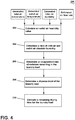
FIG. 4 is a flow diagram illustrating an example of a method of operating the control assembly ofFIG. 2 to determine characteristics of a laundry load based on the inputs from the sensors ofFIG. 3 . -
FIG. 5 is a flow diagram illustrating another example of a method of operating the control assembly ofFIG. 2 to determine characteristics of a laundry load based on the inputs from the sensors ofFIG. 3 . -
FIG. 1 is a schematic cross-sectional view of alaundry treating appliance 10 according to an aspect of the present disclosure. Thelaundry treating appliance 10 can be anylaundry treating appliance 10 which performs a cycle of operation to clean or otherwise treat laundry items placed therein, non-limiting examples of which include a horizontal or vertical axis clothes washer; a horizontal or vertical axis clothes dryer; a combination washing machine and dryer; a tumbling or stationary refreshing/revitalizing machine; an extractor; a non-aqueous washing apparatus; and a revitalizing machine. While thelaundry treating appliance 10 is illustrated herein as a horizontal axis, front-loadlaundry treating appliance 10, the aspects of the present disclosure can have applicability in laundry treating appliances with other configurations. Thelaundry treating appliance 10 shares many features of a conventional automated clothes washer and/or dryer, which will not be described in detail herein except as necessary for a complete understanding of the exemplary aspects in accordance with the present disclosure. - Laundry treating appliances are typically categorized as either a vertical axis laundry treating appliance or a horizontal axis laundry treating appliance. As used herein, the term "horizontal axis" laundry treating appliance refers to a laundry treating appliance having a rotatable drum that rotates about a generally horizontal axis relative to a surface that supports the laundry treating appliance. The drum can rotate about the axis inclined relative to the horizontal axis, with fifteen degrees of inclination being one example of the inclination. Similar to the horizontal axis laundry treating appliance, the term "vertical axis" laundry treating appliance refers to a laundry treating appliance having a rotatable drum that rotates about a generally vertical axis relative to a surface that supports the laundry treating appliance. However, the rotational axis need not be perfectly vertical to the surface. The drum can rotate about an axis inclined relative to the vertical axis, with fifteen degrees of inclination being one example of the inclination.
- In another aspect, the terms vertical axis and horizontal axis are often used as shorthand terms for the manner in which the appliance imparts mechanical energy to the laundry, even when the relevant rotational axis is not absolutely vertical or horizontal. As used herein, the "vertical axis" laundry treating appliance refers to a laundry treating appliance having a rotatable drum, perforate or imperforate, that holds fabric items and, optionally, a clothes mover, such as an agitator, impeller, nutator, and the like within the drum. The clothes mover can move within the drum to impart mechanical energy directly to the clothes or indirectly through wash liquid in the drum. The clothes mover can typically be moved in a reciprocating rotational movement. In some vertical axis laundry treating appliances, the drum rotates about a vertical axis generally perpendicular to a surface that supports the laundry treating appliance. However, the rotational axis need not be vertical. The drum can rotate about an axis inclined relative to the vertical axis.
- As used herein, the "horizontal axis" laundry treating appliance refers to a laundry treating appliance having a rotatable drum, perforated or imperforate, that holds laundry items and washes and/or dries the laundry items. In some horizontal axis laundry treating appliances, the drum rotates about a horizontal axis generally parallel to a surface that supports the laundry treating appliance. However, the rotational axis need not be horizontal. The drum can rotate about an axis inclined or declined relative to the horizontal axis. In horizontal axis laundry treating appliances, the clothes are lifted by the rotating drum and then fall in response to gravity to form a tumbling action. Mechanical energy is imparted to the clothes by the tumbling action formed by the repeated lifting and dropping of the clothes. Vertical axis and horizontal axis machines are best differentiated by the manner in which they impart mechanical energy to the fabric articles.
- Regardless of the axis of rotation, a laundry treating appliance can be top-loading or front-loading. In a top-loading laundry treating appliance, laundry items are placed into the drum through an access opening in the top of a cabinet, while in a front-loading laundry treating appliance laundry items are placed into the drum through an access opening in the front of a cabinet. If a laundry treating appliance is a top-loading horizontal axis laundry treating appliance or a front-loading vertical axis laundry treating appliance, an additional access opening is located on the drum.
- In more detail, the
laundry treating appliance 10 is illustrated as a horizontal axis combination washing and dryinglaundry treating appliance 10, though it will be understood that thelaundry treating appliance 10 need not be a combination washing and dryinglaundry treating appliance 10, but that any suitablelaundry treating appliance 10 for drying laundry items can be provided, including a clothes dryer. Thelaundry treating appliance 10 can include a structural support assembly comprising acabinet 12 which defines a housing within which a laundry holding assembly resides. Thecabinet 12 can be a housing having a chassis and/or a frame, to which decorative panels can or cannot be mounted, defining an interior, enclosing components typically found in a conventional laundry treating appliance, such as motors, pumps, fluid lines, controls, sensors, transducers, and the like. Such components will not be described further herein except as necessary for a complete understanding of the present disclosure. - The laundry holding assembly of the illustrated
laundry treating appliance 10 can include atub 14 dynamically suspended within the structural support assembly of thecabinet 12 by asuitable suspension assembly 28, thetub 14 at least partially defining a treatingchamber 18 for laundry items. Arotatable drum 16 can be provided within thetub 14 to further define at least a portion of thelaundry treating chamber 18. The treatingchamber 18 is configured to receive a laundry load comprising articles for treatment, including, but not limited to, a hat, a scarf, a glove, a sweater, a blouse, a shirt, a pair of shorts, a dress, a sock, and a pair of pants, a shoe, an undergarment, and a jacket. - The
drum 16 can include a plurality ofperforations 20 such that liquid can flow between thetub 14 and thedrum 16 through theperforations 20. A plurality ofbaffles 22 can be disposed on an inner surface of thedrum 16 to lift the laundry load received in the treatingchamber 18 while thedrum 16 rotates. It is also within the scope of the present disclosure for the laundry holding assembly to comprise only one receptacle, such as thetub 14 without thedrum 16, or thedrum 16 without thetub 14, with the single receptacle defining thelaundry treating chamber 18 for receiving the load to be treated. - The laundry holding assembly can further include a closure, illustrated herein as a
door assembly 24, which can be movably mounted to or coupled to thecabinet 12 to selectively close both thetub 14 and thedrum 16, as well as the treatingchamber 18. In one example, thedoor assembly 24 can be rotatable relative to thecabinet 12. By way of non-limiting example, thedoor assembly 24 can be hingedly coupled to thecabinet 12 for movement between an opened condition (not shown) and a closed condition as shown. - A
bellows 26 can extend between thetub 14 and thecabinet 12 to couple an open face of thetub 14 with thecabinet 12, with thedoor assembly 24 sealing against thebellows 26 or thecabinet 12, or both, when thedoor assembly 24 closes thetub 14. In the opened condition, thedoor assembly 24 can be spaced apart from thebellows 26 and can allow access to the treatingchamber 18. Thebellows 26 can sealingly couple the open face of thetub 14 with thecabinet 12 such that liquid is not permitted to move from thetub 14 into the interior of thecabinet 12. - The
laundry treating appliance 10 can optionally further comprise a washing circuit which can include a liquid supply assembly for supplying liquid, such as water or a combination of water and one or more wash aids, such as detergent, to thelaundry treating appliance 10 for use in treating laundry during a cycle of operation. The liquid supply assembly can include a source of water, such as ahousehold water supply 40, which can includeseparate valves valves valves household water supply 40, to be supplied through aninlet conduit 46 directly to thetub 14 or thedrum 16 by controlling first andsecond diverter mechanisms diverter mechanisms diverter mechanisms household water supply 40 can flow through theinlet conduit 46 to thefirst diverter mechanism 48 which can direct the flow of liquid to asupply conduit 52. Thesecond diverter mechanism 50 on thesupply conduit 52 can direct the flow of liquid to atub outlet conduit 54 which can be provided with aspray nozzle 56 configured to spray the flow of liquid into thetub 14 in a desired pattern and under a desired amount of pressure. For example, thespray nozzle 56 can be configured to dispense a flow or stream of water into thetub 14 by gravity, i.e. a non-pressurized stream. In this manner, water from thehousehold water supply 40 can be supplied directly to thetub 14. While thevalves conduit 46 are illustrated exteriorly of thecabinet 12, it will be understood that these components can be internal to thecabinet 12. - The
laundry treating appliance 10 can also optionally be provided with a dispensing assembly for dispensing treating chemistry to the treatingchamber 18 for use in treating the laundry according to a cycle of operation. The dispensing assembly can include a treatingchemistry dispenser 62 which can be a single dose dispenser, a bulk dispenser, or an integrated single dose and bulk dispenser and is fluidly coupled to the treatingchamber 18. The treatingchemistry dispenser 62 can be configured to dispense a treating chemistry directly to thetub 14 or mixed with water from the liquid supply assembly through a dispensingoutlet conduit 64. The treatingchemistry dispenser 62 can include means for supplying or mixing detergent to or with water from thewater supply 40. Alternatively or additionally, water from thewater supply 40 can also be supplied to thetub 14 through the treatingchemistry dispenser 62 without the addition of a detergent. The dispensingoutlet conduit 64 can include a dispensingnozzle 66 configured to dispense the treating chemistry into thetub 14 in a desired pattern and under a desired amount of pressure. For example, the dispensingnozzle 66 can be configured to dispense a flow or stream of treating chemistry into thetub 14 by gravity, i.e. a non-pressurized stream. Water can be supplied to the treatingchemistry dispenser 62 from thesupply conduit 52 by directing thediverter mechanism 50 to direct the flow of water to a dispensingsupply conduit 68. - The treating
chemistry dispenser 62 can include multiple chambers or reservoirs for receiving doses of different treating chemistries. The treatingchemistry dispenser 62 can be implemented as a dispensing drawer that is slidably received within thecabinet 12, or within a separate dispenser housing which can be provided in thecabinet 12. The treatingchemistry dispenser 62 can be moveable between a fill position, where the treatingchemistry dispenser 62 is exterior to thecabinet 12 and can be filled with treating chemistry, and a dispense position, where the treatingchemistry dispenser 62 are interior of thecabinet 12. - Non-limiting examples of treating chemistries that can be dispensed by the dispensing assembly during a cycle of operation include one or more of the following: water, detergents, surfactants, enzymes, fragrances, stiffness/sizing agents, wrinkle releasers/reducers, softeners, antistatic or electrostatic agents, stain repellents, water repellents, energy reduction/extraction aids, antibacterial agents, medicinal agents, vitamins, moisturizers, shrinkage inhibitors, and color fidelity agents, and combinations thereof. The treating chemistries can be in the form of a liquid, powder, or any other suitable phase or state of matter.
- The
laundry treating appliance 10 can also include a recirculation and drain assembly for recirculating liquid within the laundry holding assembly and draining liquid from thelaundry treating appliance 10. Liquid supplied to thetub 14 throughtub outlet conduit 54 and/or the dispensingsupply conduit 68 typically enters a space between thetub 14 and thedrum 16 and can flow by gravity to asump 70 formed in part by a lower portion of thetub 14. Thesump 70 can also be formed by asump conduit 72 that can fluidly couple the lower portion of thetub 14 to apump 74. Thepump 74 can have an inlet fluidly coupled with thesump 70 and an outlet configured to fluidly couple and to direct liquid to adrain conduit 76, which can drain the liquid from thelaundry treating appliance 10, or to arecirculation conduit 78, which can terminate at arecirculation inlet 80. In this configuration, thepump 74 can be used to drain or recirculate wash water in thesump 70. Therecirculation inlet 80 can direct the liquid from therecirculation conduit 78 into thedrum 16 by fluidly coupling therecirculation conduit 78 with thedrum 16. Therecirculation inlet 80 can introduce the liquid into thedrum 16 in any suitable manner, such as by spraying, dripping, or providing a steady flow of liquid. In this manner, liquid provided to thetub 14, with or without treating chemistry, can be recirculated into the treatingchamber 18 for treating the laundry within. The recirculation and drain assembly can include other types of recirculation systems. - The liquid supply and/or recirculation and drain assembly can be provided with a heating assembly which can include one or more devices for heating laundry and/or liquid supplied to the
tub 14, such as asteam generator 82 and/or asump heater 84. Liquid from thehousehold water supply 40 can be provided to thesteam generator 82 through theinlet conduit 46 by controlling thefirst diverter mechanism 48 to direct the flow of liquid to asteam supply conduit 86. Steam generated by thesteam generator 82 can be supplied to thetub 14 through asteam outlet conduit 87. Thesteam generator 82 can be any suitable type of steam generator such as a flow through steam generator or a tank-type steam generator. Alternatively, thesump heater 84 can be used to generate steam in place of or in addition to thesteam generator 82. In addition or alternatively to generating steam, thesteam generator 82 and/orsump heater 84 can be used to heat the laundry and/or liquid within thetub 14 as part of a cycle of operation. Thesump heater 84 can be provided within thesump 70 to heat liquid that collects in thesump 70. Alternatively, the heating assembly can include an in-line heater that heats the liquid as it flows through the liquid supply, dispensing, and/or recirculation assemblies. - It is noted that the illustrated suspension assembly, liquid supply assembly, recirculation and drain assembly, and dispensing assembly are shown for exemplary purposes only and are not limited to the assemblies shown in the drawings and described above. For example, the liquid supply, dispensing, and recirculation and pump assemblies can differ from the configuration shown in
FIG. 1 , such as by inclusion of other valves, conduits, treating chemistry dispensers, heaters, sensors (such as water level sensors and temperature sensors), and the like, to control the flow of liquid through thelaundry treating appliance 10 and for the introduction of more than one type of treating chemistry. For example, the liquid supply assembly can include a single valve for controlling the flow of water from the household water source. In another example, the recirculation and pump assembly can include two separate pumps for recirculation and draining, instead of the single pump as previously described. In yet another example, the liquid supply assembly can be configured to supply liquid into the interior of thedrum 16 or into the interior of thetub 14 not occupied by thedrum 16, such that liquid can be supplied directly to thetub 14 without having to travel through thedrum 16. - The
laundry treating appliance 10 also includes a drive assembly for rotating thedrum 16 within thetub 14. The drive assembly can include amotor 88, which can be directly coupled with thedrum 16 through adrive shaft 90 to rotate thedrum 16 about a rotational axis during a cycle of operation. Themotor 88 can be a brushless permanent magnet (BPM) motor having astator 92 and arotor 94. Alternately, themotor 88 can be coupled to thedrum 16 through a belt and a drive shaft to rotate thedrum 16, as is known in the art. Other motors, such as an induction motor or a permanent split capacitor (PSC) motor, can also be used. - The
motor 88 can rotationally drive thedrum 16, including that themotor 88 can rotate thedrum 16 at various speeds in either rotational direction. In particular, themotor 88 can rotate thedrum 16 at tumbling speeds wherein the laundry items in thedrum 16 rotate with thedrum 16 from a lowest location of thedrum 16 towards a highest location of thedrum 16, but fall back to the lowest location of thedrum 16 before reaching the highest location of thedrum 16. The rotation of the laundry items with thedrum 16 can be facilitated by thebaffles 22. Typically, the force applied to the laundry items at the tumbling speeds is less than about 1G. Alternatively, themotor 88 can rotate thedrum 16 at spin speeds wherein the laundry items rotate with thedrum 16 without falling. The spin speeds can also be referred to as satellizing speeds or sticking speeds. Typically, the force applied to the laundry items at the spin speeds is greater than or about equal to 1G. As used herein, "tumbling" of thedrum 16 refers to rotating thedrum 16 at a tumble speed, "spinning" thedrum 16 refers to rotating thedrum 16 at a spin speed, and "rotating" of thedrum 16 refers to rotating thedrum 16 at any speed. - The
laundry treating appliance 10 can further comprise a dryingair circuit 60 fluidly coupled to the treatingchamber 18 for drying laundry items. The dryingair circuit 60 can be a closed loop circuit or an open loop circuit. The dryingair circuit 60 can comprise a treatingchamber air inlet 58 and a treatingchamber air outlet 59, and specifically can be fluidly coupled with the treatingchamber air inlet 58 and the treatingchamber air outlet 59 and configured to supply drying air through the treatingchamber 18 from the treatingchamber air inlet 58 to the treatingchamber air outlet 59. While the treatingchamber air inlet 58 is illustrated herein as being provided on thebellows 26, it will be understood that the treatingchamber air inlet 58 can be any provided at any suitable position of the treatingchamber 18, including as an opening in at least one of thedrum 16 or thetub 14. The treatingchamber air outlet 59 is illustrated herein as being provided at a rear wall of thetub 14, thedrum 16, and the treatingchamber 18, though such a position is not limiting. The treatingchamber air inlet 58 and the treatingchamber air outlet 59 can be provided at any suitable locations of the treatingchamber 18 so long as they are spaced from one another to allow drying air to flow through the treatingchamber 18. - In one example, the drying
air circuit 60 can be provided as a closed loop, or recirculating, dryingair circuit 60, as illustrated herein. The closed loop dryingair circuit 60 can define a drying air flow pathway, as indicated by thearrows 30, to recirculate air through the treatingchamber 18. The closed loop dryingair circuit 60 can include acondenser 32, ablower 34, aheating portion 36, and a dryingair conduit 38. Thecondenser 32 can be provided with a condenser drain conduit (not shown) that fluidly couples thecondenser 32 with thepump 74 and thedrain conduit 76. Condensed liquid collected within thecondenser 32 can flow through the condenser drain conduit to thepump 74, where it can be provided to the recirculation and drain assembly. Theblower 34 is fluidly coupled to the treatingchamber 18 such that actuation of theblower 34 supplies or circulates air through the treatingchamber 18 by flowing air from the treatingchamber air inlet 58 to the treatingchamber air outlet 59. Theheating portion 36 can enclose at least one heater or heating element (not shown) that is configured to heat recirculating air that flows through the dryingair circuit 60. In one example, the dryingair circuit 60 can be provided adjacent an upper portion of thetub 14, though it will be understood that the dryingair circuit 60 need not be provided adjacent the upper portion of thetub 14, and can be provided at any suitable location adjacent thetub 14 or the treatingchamber 18. - In one example, the drying
air flow pathway 30 can pass through the components of the closed loop dryingair circuit 60 such that air exiting the treatingchamber 18 through the treatingchamber air outlet 59 flows through thecondenser 32, through theblower 34, through theheating portion 36 to be heated to become drying air, and then through the dryingair conduit 38 to enter the treatingchamber 18 through the treatingchamber air inlet 58. However, while theblower 34 is illustrated herein as being provided in between thecondenser 32 and theheating portion 36, and specifically downstream of thecondenser 32 and upstream of theheating portion 36, it will be understood that theblower 34 can be provided at any suitable location within the dryingair circuit 60 so as to drive the supply of air along the dryingair flow pathway 30. By way of non-limiting example, theblower 34 can be provided between the treatingchamber air outlet 59 and thecondenser 32 or between theheating portion 36 and the treatingchamber air inlet 58. Further, while the closed loop dryingair circuit 60 is illustrated herein as including both thecondenser 32 and theheating portion 36, it will be understood that the closed loop dryingair circuit 60 could also include thecondenser 32, but not theheating portion 36, or could include theheating portion 36, but not thecondenser 32. - When the drying
air circuit 60 is provided as an open loop dryingair circuit 60, thecondenser 32 is not necessary. Alternatively, theblower 34, instead of being fluidly coupled with thecondenser 32, can be fluidly coupled with an ambient air source, which can draw ambient air either from within thecabinet 12 or from the exterior of thecabinet 12. The ambient air can be provided from theblower 34 to theheating portion 36 to be heated to be provided through the dryingair conduit 38 to enter the treatingchamber 18 through the treatingchamber air inlet 58. Air that flows through the treatingchamber 18 and gathers moisture from the laundry items within the treatingchamber 18, and is then exhausted through the treatingchamber air outlet 59 and can be exhausted to the exterior of thecabinet 12. As the drying air is not being recirculated to the treatingchamber 18, no condensing is necessary. In such an example, while theblower 34 is illustrated as being provided upstream of theheating portion 36, it will also be understood that theblower 34 can be provided between theheating portion 36 and the treatingchamber air inlet 58. Additionally or alternatively, thesame blower 34 or anadditional blower 34 can be provided downstream of the treatingchamber air outlet 59 to draw the exhaust air out of the treatingchamber 18. - The
laundry treating appliance 10 also includes a control assembly for controlling the operation of thelaundry treating appliance 10 and its various working components to control the operation of the working components and to implement one or more treating cycles of operation. The control assembly can include acontroller 96 located within thecabinet 12 and auser interface 98 that is operably coupled with thecontroller 96. Theuser interface 98 can provide an input and output function for thecontroller 96. In one example, theuser interface 98 can be provided or integrated with thedoor assembly 24. In another example, as shown, theuser interface 98 can be provided on a front panel of thecabinet 12. - The
user interface 98 can include one or more knobs, dials, switches, displays, touch screens and the like for communicating with the user, such as to receive input and provide output. For example, the displays can include any suitable communication technology including that of a liquid crystal display (LCD), a light-emitting diode (LED) array, or any suitable display that can convey a message to the user. The user can enter different types of information including, without limitation, cycle selection and cycle parameters, such as cycle options. Other communications paths and methods can also be included in thelaundry treating appliance 10 and can allow thecontroller 96 to communicate with the user in a variety of ways. For example, thecontroller 96 can be configured to send a text message to the user, send an electronic mail to the user, or provide audio information to the user either through thelaundry treating appliance 10 or utilizing another device such as a mobile phone. - The
controller 96 can include the machine controller and any additional controllers provided for controlling any of the components of thelaundry treating appliance 10. For example, thecontroller 96 can include the machine controller and a motor controller. Many known types of controllers can be used for thecontroller 96. It is contemplated that the controller is a microprocessor-based controller that implements control software and sends/receives one or more electrical signals to/from each of the various working components to effect the control software. As an example, proportional control (P), proportional integral control (PI), and proportional derivative control (PD), or a combination thereof, a proportional integral derivative control (PID control), can be used to control the various components. - As illustrated in
FIG. 2 , thecontroller 96 can be provided with amemory 100 and a central processing unit (CPU) 102. Thememory 100 can be used for storing the control software that is executed by theCPU 102 in completing a cycle of operation using thelaundry treating appliance 10 and any additional software. For example, thememory 100 can store a set of executable instructions including at least one user-selectable cycle of operation. Examples, without limitation, of cycles of operation include: wash, heavy duty wash, delicate wash, quick wash, pre-wash, refresh, rinse only, timed wash, dry, heavy duty dry, delicate dry, quick dry, or automatic dry, which can be selected at theuser interface 98. Thememory 100 can also be used to store information, such as a database or table, and to store data received from one or more components of thelaundry treating appliance 10 that can be communicably coupled with thecontroller 96. The database or table can be used to store the various operating parameters for the one or more cycles of operation, including factory default values for the operating parameters and any adjustments to them by the control assembly or by user input. - The
controller 96 can be operably coupled with one or more components of thelaundry treating appliance 10 for communicating with and controlling the operation of the component to complete a cycle of operation. For example, thecontroller 96 can be operably coupled with thevalves diverter mechanisms chamber 18, themotor 88 for controlling the direction and speed of rotation of thedrum 16, thepump 74 for controlling the amount of treating liquid in the treatingchamber 18 orsump 70, the treatingchemistry dispenser 62 for controlling the flow of treating chemistries into the treatingchamber 18, theuser interface 98 for receiving user selected inputs and communicating information to the user, thesteam generator 82, thesump heater 84, and the dryingair circuit 60, including theblower 34 and theheating portion 36, to control the operation of these and other components to implement one or more of the cycles of operation. - The
controller 96 can also be coupled with one ormore sensors 104 provided in one or more of the assemblies of thelaundry treating appliance 10 to receive input from thesensors 104, which are known in the art and not shown for simplicity. Non-limiting examples ofsensors 104 that can be communicably coupled with thecontroller 96 include: a treating chamber temperature sensor, such as a thermistor, which can detect the temperature of the treating liquid in the treatingchamber 18 and/or the temperature of the treating liquid being supplied to the treatingchamber 18, a moisture sensor, a weight sensor, a chemical sensor, a position sensor, an imbalance sensor, a load size sensor, and a motor torque sensor, which can be used to determine a variety of assembly and laundry characteristics, such as laundry load inertia or mass. In one example, a characteristic that can be determined by thecontroller 96 based on input fromsensors 104 can include an estimated or assumed air flow rate or mass flow level through the dryingair circuit 60 and/or through the treatingchamber 18. - In one specific example, the
laundry treating appliance 10 can include a first temperature sensor 110, a second temperature sensor 112, a first humidity sensor 114, and optionally a second humidity sensor 116, all of which are operably and communicably coupled with thecontroller 96 for use in determining an evaporation rate of moisture remaining in the laundry load, a dryness level of the laundry load, and an estimated remaining drying time for the laundry load. These sensors 110, 112, 114, 116 can be provided at a variety of locations within thelaundry treating appliance 10, as will be discussed further. Depending on the location of the sensors 110, 112, 114, 116, it may be beneficial to provide structures to protect the sensors 110, 112, 114, 116 from the environment of thelaundry treating appliance 10, such as shields or doors to protect from liquid, or mesh screens to protect from lint. - Referring now to
FIG. 3 , amethod 150 of operating thecontroller 96 to receive and process signals from the first temperature sensor 110, the second temperature sensor 112, the first humidity sensor 114, and optionally the second humidity sensor 116, is described. Traditional methods of estimating the dryness of a laundry load and an estimated drying time remaining for the laundry load may rely on imprecise sensors, such as moisture strips, that lose sensitivity and accuracy once the moisture level in the laundry load falls below a particular point. Thus, more precise methods of estimating dryness of a laundry load and estimated drying time remaining can offer an improvement. However, precise sensors result in increased cost. Thus, it can be useful to develop methods of determining these values while minimizing the additional sensors needed, such as by using outputs from one sensor to estimate or calculate a related value without the cost of including an additional sensor to directly sense the related value. One example of such a strategy is to provide thecontroller 96 for determining the evaporation rate of moisture remaining in the laundry load, the dryness level of the laundry load, and an estimated remaining drying time for the laundry load, based on the inputs from the first temperature sensor 110, the second temperature sensor 112, and the first humidity sensor 114, without the need for the second humidity sensor 116. Instead of including the second humidity sensor 116 and its associated cost, the inputs from the first temperature sensor 110, the second temperature sensor 112, and the first humidity sensor 114 can be used to calculate or estimate a humidity value that would otherwise be sensed by the second humidity sensor 116, which is then used in the determination of the evaporation rate, the dryness level, and the estimated remaining drying time. - The first temperature sensor 110 can be provided in the drying
air circuit 60 and, at 152, configured to sense a signal indicative of an inlet air temperature of the air entering the treatingchamber 18 through the treatingchamber air inlet 58. The first temperature sensor 110 can be any suitable type of temperature sensor. The first temperature sensor 110 can directly sense the inlet air temperature, or it can sense a signal indicative of the inlet air temperature, by way of non-limiting example, a voltage or the like, which can be converted into a value corresponding to the inlet air temperature or used without conversion to determine the inlet air temperature value. At 154, the first temperature sensor 110 then provides a signal indicative of the inlet air temperature to thecontroller 96. At 156, thecontroller 96 receives the signal indicative of the inlet air temperature from the first temperature sensor 110 and, at 158, processes the signal from the first temperature sensor 110, and further, at 160, generates the inlet air temperature from the signal received from the first temperature sensor 110. The first temperature sensor 110 can be provided at any suitable location within the dryingair circuit 60 such that it can sense the inlet air temperature. By way of non-limiting example, the first temperature sensor 110 can be provided adjacent the treatingchamber air inlet 58, between theheating portion 36 and the treatingchamber air inlet 58 such that the first temperature sensor 110 is downstream of theheating portion 36 and upstream of the treatingchamber air inlet 58, or, in the case that theheating portion 36 is not included, between thecondenser 32 and the treatingchamber air inlet 58. In the case that the dryingair circuit 60 is an open loop dryingair circuit 60, the first temperature sensor 110 can be provided at a cabinet inlet where ambient air enters thecabinet 12. - The second temperature sensor 112 can be provided in the drying
air circuit 60 and, at 152, configured to sense a signal indicative of an outlet air temperature of the air exiting the treatingchamber 18 through the treatingchamber air outlet 59. The second temperature sensor 112 can be any suitable type of temperature sensor. The second temperature sensor 112 can directly sense the outlet air temperature, or it can sense a signal indicative of the outlet air temperature, by way of non-limiting example, a voltage or the like, which can be converted into a value corresponding to the outlet air temperature or used without conversion to determine the outlet air temperature value. At 154, the second temperature sensor 112 then provides a signal indicative of the outlet air temperature to thecontroller 96. At 156, thecontroller 96 receives the signal indicative of the outlet air temperature from the second temperature sensor 112 and, at 158, processes the signal from the second temperature sensor 112, and further, at 160, generates the outlet air temperature from the signal received from the second temperature sensor 112. The second temperature sensor 112 can be provided at any suitable location within the dryingair circuit 60 such that it can sense the outlet air temperature. By way of non-limiting example, the second temperature sensor 112 can be provided adjacent the treatingchamber air outlet 59, between the treatingchamber air outlet 59 and either thecondenser 32 or theheating portion 36, or between the treatingchamber air inlet 58 and either thecondenser 32 or theheating portion 36. In the case that the dryingair circuit 60 is an open loop dryingair circuit 60, the second temperature sensor 112 can be provided at a cabinet exhaust where the air is exhausted from and exits thecabinet 12. - The first humidity sensor 114 can be provided in the drying
air circuit 60 and, at 152, configured to sense a signal indicative of an inlet air humidity value of the air entering the treatingchamber 18 through the treatingchamber air inlet 58. The first humidity sensor 114 can be any suitable type of humidity sensor. The first humidity sensor 114 can directly sense the inlet air humidity, or it can sense a signal indicative of the inlet air humidity, by way of non-limiting example, a voltage or the like, which can be converted into a value corresponding to the inlet air humidity or used without conversion to determine the inlet air humidity value. At 154, the first humidity sensor 114 then provides a signal indicative of the inlet air humidity to thecontroller 96. At 156, thecontroller 96 receives the signal indicative of the inlet air humidity from the first humidity sensor 114 and, at 158, processes the signal from the first humidity sensor 114, and further, at 160, generates the inlet air humidity value from the signal received from the first humidity sensor 114. In one example, the generated inlet air humidity value is an inlet air relative humidity value. The first humidity sensor 114 can be provided at any suitable location within the dryingair circuit 60 such that it can sense the inlet air humidity. By way of non-limiting example, the first humidity sensor 114 can be provided adjacent the treatingchamber air inlet 58, between theheating portion 36 and the treatingchamber air inlet 58 such that the first humidity sensor 114 is downstream of theheating portion 36 and upstream of the treatingchamber air inlet 58, or, in the case that theheating portion 36 is not included, between thecondenser 32 and the treatingchamber air inlet 58. In the case that the dryingair circuit 60 is an open loop dryingair circuit 60, the first humidity sensor 114 can be provided at a cabinet inlet where ambient air enters thecabinet 12. - As described previously, methods are disclosed herein for estimating a humidity value that could otherwise be sensed by the second humidity sensor 116, by using the outputs from the first temperature sensor 110, the second temperature sensor 112, and the first humidity sensor 114 to calculate or estimate such a humidity value. In this way, the additional cost of providing the second humidity sensor 116 is avoided. However, in some cases, increased precision in determining the remaining drying time may be desired, or an example
laundry treating appliance 10 may already include a second humidity sensor 116. In such cases, the second humidity sensor 116 can be included and its output used in the determinations made by thecontroller 96. In these cases, thelaundry treating appliance 10 can optionally further include the second humidity sensor 116. The second humidity sensor 116 can be provided in the dryingair circuit 60 and, at 152, configured to sense a signal indicative of an outlet air humidity value of the air exiting the treatingchamber 18 through the treatingchamber air outlet 59. The second humidity sensor 116 can be any suitable type of humidity sensor. The second humidity sensor 116 can directly sense the outlet air humidity, or it can sense a signal indicative of the outlet air humidity, by way of non-limiting example, a voltage or the like, which can be converted into a value corresponding to the outlet air humidity or used without conversion to determine the outlet air humidity value. At 154, the second humidity sensor 116 then provides a signal indicative of the outlet air humidity to thecontroller 96. At 156, thecontroller 96 receives the signal indicative of the outlet air humidity from the second humidity sensor 116 and, at 158, processes the signal from the second humidity sensor 116, and further, at 160, generates the outlet air humidity value from the signal received from the second humidity sensor 116. In one example, the generated outlet air humidity value is an outlet air relative humidity value. The second humidity sensor 116 can be provided at any suitable location within the dryingair circuit 60 such that it can sense the outlet air humidity. By way of non-limiting example, the second humidity sensor 116 can be provided adjacent the treatingchamber air outlet 59, between the treatingchamber air outlet 59 and either thecondenser 32 or theheating portion 36, or between the treatingchamber air inlet 58 and either thecondenser 32 or theheating portion 36. In the case that the dryingair circuit 60 is an open loop dryingair circuit 60, the second humidity sensor 116 can be provided at a cabinet exhaust where the air is exhausted from and exits thecabinet 12. - Referring now to
FIG. 4 , amethod 200 of operating thecontroller 96 to determine an evaporation rate of moisture remaining in the laundry load, a dryness level of the laundry load, and an estimated remaining drying time for the laundry load using the first temperature sensor 110, the second temperature sensor 112, and the first humidity sensor 114 is described. At 202, using the generated inlet air temperature, the generated outlet air temperature, the generated inlet air relative humidity, and the estimated air flow rate determined by thecontroller 96 as inputs to an algorithm or model, thecontroller 96 is further configured to determine, such as by calculating or estimating, an outlet air humidity value of the air exiting the treatingchamber 18 at the treatingchamber air outlet 59, without the need for and the cost of including the second humidity sensor 116. At 204, and using the same inputs as at 202 and additionally using the determined outlet air humidity value as an input, thecontroller 96 determines an inlet air absolute humidity value and an outlet air absolute humidity value, based upon the sensed and determined relative humidity values and together with inlet air and outlet air temperatures, then calculates a ratio of the absolute humidity of the inlet air and the outlet air. Specifically, absolute humidity can be calculated based on relative humidity, along with inlet air temperature and outlet air temperature. At 206, based on the calculated ratio of the absolute humidity of the inlet air and the outlet air, thecontroller 96 determines an evaporation rate of the moisture remaining in the laundry load within the treatingchamber 18. At 208, thecontroller 96 determines a dryness level of the laundry load, based upon the generated input values and the calculated evaporation rate of the laundry load. At 210, thecontroller 96 estimates a remaining drying time for the laundry load based on the dryness level of the laundry load and the calculated evaporation rate of the laundry load. - Referring now to
FIG. 5 , amethod 300 of operating thecontroller 96 to determine an evaporation rate of moisture remaining in the laundry load, a dryness level of the laundry load, and an estimated remaining drying time for the laundry load using the first temperature sensor 110, the second temperature sensor 112, the first humidity sensor 114, and the second humidity sensor 116 is described. As described previously, in some cases it is desirable to omit the second humidity sensor 116 in order to save costs, and this can be accomplished by the methods of estimating outlet air humidity as discussed. However, in other cases, the particularlaundry treating appliance 10 may already include the second humidity sensor 116, or it may be the case that the improved precision of the estimated remaining drying time obtained when the second humidity sensor 116 is included may outweigh the increased cost of including the second humidity sensor 116. In such cases, and because the second humidity sensor 116 provides a generated outlet air humidity value as an input to thecontroller 96, it is not necessary to calculate the outlet air humidity value as atstep 202 of themethod 200. In themethod 300, rather, and at 304, using the generated inlet air temperature, the generated outlet air temperature, the generated inlet air relative humidity, and the generated outlet air relative humidity determined by thecontroller 96 as inputs to an algorithm or model, thecontroller 96 determines an inlet air absolute humidity value and an outlet air absolute humidity value, then calculates a ratio of the absolute humidity of the inlet air and the outlet air. At 306, based on the calculated ratio of the absolute humidity of the inlet air and the outlet air, thecontroller 96 determines an evaporation rate of the moisture remaining in the laundry load within the treatingchamber 18. At 308, thecontroller 96 determines a dryness level of the laundry load, based upon the generated input values and the calculated evaporation rate of the laundry load. At 310, thecontroller 96 estimates a remaining drying time for the laundry load based on the dryness level of the laundry load and the calculated evaporation rate of the laundry load. - While the
methods - The aspects of the present disclosure described herein set forth apparatus and methods for improved accuracy and precision in estimating a remaining drying time of a laundry load and of a targeted dryness level of the laundry load. Traditional moisture detection methods for clothes loads being dried include the use of moisture strips, which tend to exhibit loss of electrical signal once the moisture content in the laundry load drops below 15-20%. The methods described herein allow for accurate and precise moisture detection throughout the dryness range of the laundry load. The inclusion of such sensors as a humidity sensor at a cabinet inlet can further improve algorithm inputs by assessing the environmental conditions that can vary with geographic region or season of the year. Even with the addition of only one inlet air humidity sensor, improved accuracy over tradition methods can be realized. With the addition of first and second humidity sensors for inlet air and outlet air, the calculation becomes even more accurate. The calculations and determinations disclosed herein can also allow for incorporating load type for further accuracy, and can even be used for avoiding unwanted static electricity in the laundry load by ensuring that drying is stopped when a sufficient amount of moisture remains in the laundry load such that the laundry load feels dry to a user, but is not over-dry so as to result in static.
- To the extent not already described, the different features and structures of the various aspects can be used in combination with each other as desired. That one feature is not illustrated in all of the aspects is not meant to be construed that it cannot be, but is done for brevity of description. Thus, the various features of the different aspects can be mixed and matched as desired to form new aspects, whether or not the new aspects are expressly described.
- It is intended that the following concepts can define at least a portion of the scope of the disclosure and that the apparatus and/or method(s) within the scope of these concepts and their equivalents be covered thereby. This disclosure should be understood to include all novel and non-obvious combinations of elements described herein, and the concepts may be presented in this or a later application to any novel and non-obvious combination of these elements. Any aspect of any embodiment can be combined any aspect of any of the other embodiments. Moreover, the foregoing embodiments are illustrative, and no single feature or element is essential to all possible combinations that may be included in this or a later application. For example, other inventions arising from this disclosure may include any combination of the following concepts set forth in outline form:
- A method of operating a laundry treating appliance with a treating chamber for treating a load of laundry according to a drying cycle of operation, the method comprising:
- supplying, by a drying air circuit, drying air to the treating chamber during the drying cycle of operation;
- sensing, with a first air temperature sensor provided in the drying air circuit, a first signal indicative of an inlet air temperature of the drying air in the drying air circuit that flows through a treating chamber air inlet;
- sensing, with a second air temperature sensor provided in the drying air circuit, a second signal indicative of an outlet air temperature of the drying air exiting a treating chamber air outlet;
- sensing, with at least a first humidity sensor provided in the drying air circuit, a third signal indicative of an inlet air humidity value of the drying air entering the treating chamber air inlet;
- estimating, by a controller, an air flow rate through the treating chamber;
- determining, by the controller, an outlet air humidity value based on the first, second, and third signals and the estimated air flow rate; and
- estimating, by the controller, a remaining drying time for the load of laundry based on the determined outlet air humidity value.
- The method further comprising determining, by the controller, an evaporation rate of moisture remaining in the load of laundry based on the determined outlet air humidity value.
- The method further comprising determining, by the controller, a dryness level of the load of laundry based on the determined evaporation rate of moisture remaining in the load of laundry.
- The method wherein the estimating, by the controller, a remaining drying time for the load of laundry is based on the determined dryness level and the determined evaporation rate of the load of laundry.
- The method further comprising:
- sensing, with a second humidity sensor provided in the drying air circuit, a fourth signal indicative of an outlet air humidity value of the drying air exiting the treating chamber air outlet; and
- determining, by the controller, an evaporation rate of moisture remaining in the load of laundry based on the first, second, third, and fourth signals.
- This written description uses examples to disclose aspects of the disclosure, including the best mode, and also to enable any person skilled in the art to practice aspects of the disclosure, including making and using any devices or systems and performing any incorporated methods. While aspects of the disclosure have been specifically described in connection with certain specific details thereof, it is to be understood that this is by way of illustration and not of limitation. Reasonable variation and modification are possible within the scope of the forgoing disclosure and drawings without departing from the spirit of the disclosure, which is defined in the appended claims.
Claims (15)
- A laundry treating appliance (10) for treating laundry according to an automatic cycle of operation, the laundry treating appliance (10) comprising:a cabinet (12) defining a cabinet interior;a drum (16), rotatable within the cabinet interior, and at least partially defining a treating chamber (18), the treating chamber (18) having a treating chamber air inlet (58) and a treating chamber air outlet (59);a drying air circuit (60) fluidly coupled to the treating chamber air inlet (58) and to the treating chamber air outlet (59);a first air temperature sensor (110) provided in the drying air circuit (60) and outputting a first signal indicative of an inlet air temperature of drying air in the drying air circuit (60) that flows through the treating chamber air inlet (58);a second air temperature sensor (112) provided in the drying air circuit (60) and outputting a second signal indicative of an outlet air temperature of the drying air exiting the treating chamber air outlet (59);at least a first humidity sensor (114) provided in the drying air circuit (60) and outputting a third signal indicative of an inlet air humidity value of the drying air entering the treating chamber air inlet (58); anda controller (96) estimating an air flow rate through the drying air circuit (60), and further operably coupled with the first and second air temperature sensors (110, 112) and the first humidity sensor (114) to receive and process the first, second, and third signals and the estimated air flow rate to determine an outlet air humidity value of the drying air exiting the treating chamber air outlet (59) and to estimate a remaining drying time for the laundry based on the determined outlet air humidity value.
- The laundry treating appliance (10) of claim 1 wherein the controller (96) further determines an evaporation rate of moisture remaining in the laundry based on the determined outlet air humidity value.
- The laundry treating appliance (10) of claim 2 wherein the controller (96) further determines a dryness level of the laundry based on the determined evaporation rate of moisture remaining in the laundry.
- The laundry treating appliance (10) of claim 3 wherein the estimated remaining drying time for the laundry is based on the determined dryness level and the determined evaporation rate of the laundry.
- The laundry treating appliance (10) of claim 1 further comprising a second humidity sensor (116) provided in the drying air circuit (60) and outputting a fourth signal indicative of an outlet air humidity value of the drying air exiting the treating chamber air outlet (59).
- The laundry treating appliance (10) of claim 5 wherein the controller (96) is operably coupled with the second humidity sensor (116) to receive and process the fourth signal to determine an evaporation rate of moisture remaining in the laundry based on the inlet air temperature, the outlet air temperature, the inlet air humidity value, and the outlet air humidity value.
- The laundry treating appliance (10) of claim 6 wherein the determined evaporation rate of moisture remaining in the laundry is further based on the estimated air flow rate.
- The laundry treating appliance (10) of any of previous claims wherein the inlet air humidity value is a relative humidity value.
- The laundry treating appliance (10) of claim 8 wherein the controller (96) determines an absolute inlet air humidity value based on the inlet air temperature, the outlet air temperature, and the inlet air relative humidity value.
- The laundry treating appliance (10) of any of previous claims wherein the laundry treating appliance is a combination washing and drying treating appliance.
- The laundry treating appliance (10) of claim 10 further comprising a tub (14) defining a tub interior, the drum (16) provided within the tub interior, and the tub interior configured to receive wash liquid during a washing cycle of operation.
- The laundry treating appliance (10) of claim 10 wherein the treating chamber (18) holds laundry for washing and/or drying treatment.
- The laundry treating appliance (10) of any of previous claims wherein the drying air circuit (60) is one of a closed loop circuit and an open loop circuit.
- The laundry treating appliance (10) of any of previous claims wherein the drying air circuit (60) comprises a blower (34) fluidly coupled to the treating chamber (18), whereby actuation of the blower (34) circulates air through the treating chamber (18) by flowing air from the treating chamber air inlet (58) to the treating chamber air outlet (59).
- The laundry treating appliance (10) of claim 14 wherein the air flowing from the treating chamber air inlet (58) to the treating chamber air outlet (59) is returned to the treating chamber air inlet (58) via the drying air circuit (60).
Applications Claiming Priority (1)
| Application Number | Priority Date | Filing Date | Title |
|---|---|---|---|
| US16/586,857 US11008697B2 (en) | 2019-09-27 | 2019-09-27 | Laundry treating appliance having sensors, and methods of operation |
Publications (1)
| Publication Number | Publication Date |
|---|---|
| EP3798355A1 true EP3798355A1 (en) | 2021-03-31 |
Family
ID=72644086
Family Applications (1)
| Application Number | Title | Priority Date | Filing Date |
|---|---|---|---|
| EP20197931.7A Withdrawn EP3798355A1 (en) | 2019-09-27 | 2020-09-23 | Laundry treating appliance having sensors |
Country Status (3)
| Country | Link |
|---|---|
| US (3) | US11008697B2 (en) |
| EP (1) | EP3798355A1 (en) |
| CN (1) | CN112575497B (en) |
Cited By (2)
| Publication number | Priority date | Publication date | Assignee | Title |
|---|---|---|---|---|
| US20210254268A1 (en) * | 2019-09-27 | 2021-08-19 | Whirlpool Corporation | Laundry treating appliance having sensors, and methods of operation |
| CN116817572A (en) * | 2023-08-31 | 2023-09-29 | 昆明冬冬食品有限公司 | Drying equipment for food processing with heat recycling function |
Families Citing this family (7)
| Publication number | Priority date | Publication date | Assignee | Title |
|---|---|---|---|---|
| KR102777298B1 (en) * | 2019-08-21 | 2025-03-10 | 엘지전자 주식회사 | Drying method using intelligent washing machine and apparatus therefor |
| KR102862653B1 (en) * | 2019-10-25 | 2025-09-23 | 삼성전자주식회사 | Dryer and controlling method thereof |
| US11603624B2 (en) * | 2020-12-10 | 2023-03-14 | Haier Us Appliance Solutions, Inc. | Lint filter clogging detection in a dryer appliance based on airflow |
| CN116180387B (en) * | 2021-11-26 | 2025-05-16 | 无锡小天鹅电器有限公司 | A control method for a combined washer-dryer and a combined washer-dryer |
| US12252828B2 (en) | 2022-07-28 | 2025-03-18 | Whirlpool Corporation | Combination washing and drying laundry treating appliance |
| US20240301615A1 (en) * | 2023-03-09 | 2024-09-12 | Whirlpool Corporation | Particulate removal system for laundry drying appliances |
| US20240352638A1 (en) * | 2023-04-24 | 2024-10-24 | Whirlpool Corporation | Method and system for determining and estimated time remaining for a dryer system |
Citations (4)
| Publication number | Priority date | Publication date | Assignee | Title |
|---|---|---|---|---|
| US6122840A (en) * | 1998-11-18 | 2000-09-26 | General Electric Company | Systems and methods for determining drying time for a clothes dryer |
| EP2487291A1 (en) * | 2011-02-11 | 2012-08-15 | Electrolux Home Products Corporation N.V. | Rotatable-drum laundry drier and method of controlling a rotatable-drum laundry drier to dry delicate laundry |
| EP2653602A1 (en) * | 2012-04-19 | 2013-10-23 | Whirpool Corporation | Method for detecting the cycle termination of a household tumble dryer |
| EP3284860A1 (en) * | 2015-04-17 | 2018-02-21 | Qingdao Haier Washing Machine Co., Ltd. | Method and device for determining drying time of clothes dryer |
Family Cites Families (55)
| Publication number | Priority date | Publication date | Assignee | Title |
|---|---|---|---|---|
| KR940006250B1 (en) | 1991-12-23 | 1994-07-13 | 주식회사 금성사 | Drying control method and circuit of complex sensor type |
| CA2588105C (en) | 2000-05-02 | 2011-09-13 | General Electric Company | A system and method for controlling a dryer appliance |
| US6845290B1 (en) | 2000-05-02 | 2005-01-18 | General Electric Company | System and method for controlling a dryer appliance |
| RU2006114770A (en) | 2003-09-29 | 2007-11-10 | Селф Пропеллед Рисерч энд Дивелопмент Спешелистс,эЛэЛСи (US) | DRYING DEVICE (OPTIONS), WASHING DEVICE AND DRYING CHAMBER (OPTIONS) |
| US7695524B2 (en) * | 2003-10-31 | 2010-04-13 | Whirlpool Corporation | Non-aqueous washing machine and methods |
| US7739891B2 (en) * | 2003-10-31 | 2010-06-22 | Whirlpool Corporation | Fabric laundering apparatus adapted for using a select rinse fluid |
| US7900374B2 (en) | 2004-08-18 | 2011-03-08 | Lg Electronics Inc. | Apparatus for automatically drying and method for controlling the same |
| KR101138139B1 (en) | 2004-10-26 | 2012-04-23 | 엘지전자 주식회사 | A condensing type dryer and method of controlling the same |
| KR100697070B1 (en) * | 2004-11-06 | 2007-03-20 | 엘지전자 주식회사 | Dryers, Laundry Dryers and Control Methods |
| CN1973077B (en) * | 2004-12-06 | 2011-08-03 | Lg电子株式会社 | clothes dryer |
| EP1819869B1 (en) * | 2004-12-06 | 2014-06-11 | LG Electronics Inc. | Clothes dryer |
| US7694538B2 (en) | 2005-02-14 | 2010-04-13 | Emerson Electric Co. | Device and method for sensing temperature of a rotating electromagnetic machine |
| US20070124953A1 (en) | 2005-12-02 | 2007-06-07 | Robertshaw Controls Company | Clothes Dryer Fire Alarm |
| US8839527B2 (en) | 2006-02-21 | 2014-09-23 | Goji Limited | Drying apparatus and methods and accessories for use therewith |
| US8312638B2 (en) * | 2006-08-23 | 2012-11-20 | Lg Electronics Inc. | Multiple laundry treating machine |
| KR101276815B1 (en) | 2006-08-29 | 2013-06-18 | 엘지전자 주식회사 | Pedestal Drying Machine |
| CA2599353C (en) * | 2006-09-06 | 2011-05-24 | Lg Electronics Inc. | Dryer with clogging detecting function |
| CN101168895A (en) * | 2006-10-23 | 2008-04-30 | 南京乐金熊猫电器有限公司 | Drying method for washing device |
| JP4889545B2 (en) | 2007-03-30 | 2012-03-07 | 三洋電機株式会社 | Drying apparatus and washing and drying machine equipped with this apparatus |
| US20090272004A1 (en) * | 2008-05-01 | 2009-11-05 | Whirlpool Corporation | Intelligent dispensing in a laundry appliance |
| US7870799B2 (en) | 2008-09-11 | 2011-01-18 | Whirlpool Corporation | Method and apparatus for testing the air flow in a clothes dryer |
| US8443527B2 (en) | 2009-12-18 | 2013-05-21 | Whirlpool Corporation | Fabric temperature estimation for a laundry dryer |
| CN101787638A (en) * | 2009-12-31 | 2010-07-28 | 深圳和而泰智能控制股份有限公司 | Method and device for intelligently detecting and controlling clothes dryer |
| EP2460926A1 (en) * | 2010-12-02 | 2012-06-06 | Electrolux Home Products Corporation N.V. | Heat pump dryer |
| KR20120065628A (en) | 2010-12-13 | 2012-06-21 | 삼성전자주식회사 | Dryer |
| US9834882B2 (en) * | 2011-07-07 | 2017-12-05 | Haier Us Appliance Solutions, Inc. | Device and method for heat pump based clothes dryer |
| DE102011078916A1 (en) | 2011-07-11 | 2013-01-17 | Bosch-Siemens Hausgeräte Gmbh | Clothes dryer for use with fire protection device for preventing or combating fire inside clothes dryer, has sensor for detecting fire-related parameters, where microcontroller is provided for controlling activation of actuator |
| US9206543B2 (en) | 2011-10-14 | 2015-12-08 | Ecolab Usa Inc. | Dryer monitoring |
| EP2612963B1 (en) * | 2012-01-05 | 2016-03-30 | Electrolux Home Products Corporation N.V. | Appliance for drying laundry |
| US9895044B2 (en) * | 2012-08-28 | 2018-02-20 | Whirlpool Corporation | Dishwasher with controlled dry cycle |
| EP2746455A1 (en) * | 2012-12-20 | 2014-06-25 | BSH Bosch und Siemens Hausgeräte GmbH | Process for operating a washer dryer with a heat pump, and a suitable washer dryer |
| MX358870B (en) * | 2014-04-16 | 2018-09-04 | Mabe Sa De Cv | Intelligent electronic system for previously sensing the dryness condition of a textile clothes load in an automatic electronic clothes dryer machine. |
| EP2977503B1 (en) * | 2014-07-25 | 2019-04-24 | Electrolux Appliances Aktiebolag | Laundry drying apparatus with heater unit having adjustable temperature thresholds |
| US10113262B2 (en) | 2014-08-06 | 2018-10-30 | Haier Us Appliance Solutions, Inc. | Dryer appliances and methods for diagnosing restrictions in dryer appliances |
| KR101613965B1 (en) | 2014-12-08 | 2016-04-20 | 엘지전자 주식회사 | Control method for exhaust-type dryer |
| EP3059342B1 (en) | 2015-02-20 | 2022-11-09 | Electrolux Appliances Aktiebolag | Method of operating a laundry treatment apparatus using operation state information |
| US10138590B2 (en) | 2015-03-20 | 2018-11-27 | Whirlpool Corporation | Method for drying laundry in a laundry treating appliance |
| WO2017004450A1 (en) | 2015-07-02 | 2017-01-05 | The Regents Of The University Of California | Self-calibrating automatic controller to determine end of cycle and track dryer cycle efficiency |
| US9783925B1 (en) | 2016-04-12 | 2017-10-10 | Haier Us Appliance Solutions, Inc. | Dryer appliances and methods of operation |
| CN108004733B (en) | 2016-10-31 | 2020-04-17 | 众智光电科技股份有限公司 | Clothes dryer |
| BR112019013090B1 (en) | 2016-12-28 | 2022-10-04 | Electrolux Appliances Aktiebolag | APPLIANCE |
| US10181245B2 (en) | 2016-12-29 | 2019-01-15 | Nortek Security & Control Llc | Dryer vent monitoring device |
| US10443182B2 (en) * | 2016-12-29 | 2019-10-15 | Whirlpool Corporation | Customer selection of desired remaining moisture in clothing via user interface at machine or portable electronic device |
| US10808351B1 (en) | 2017-01-06 | 2020-10-20 | United Services Automobile Association (Usaa) | Appliance monitoring sensors |
| US20180245276A1 (en) | 2017-02-27 | 2018-08-30 | Garrett P. Borden | Apparatus to prevent clogging of dryer vents |
| US10704189B2 (en) * | 2017-08-25 | 2020-07-07 | Whirlpool Corporation | Laundry appliance having an ultrasonic drying mechanism |
| US10738409B2 (en) * | 2017-10-31 | 2020-08-11 | Whirlpool Corporation | Laundry treating appliance with a sensor |
| US10557229B2 (en) | 2018-03-21 | 2020-02-11 | Haier Us Appliance Solutions, Inc. | Blockage detection in a dryer appliance |
| US10669667B2 (en) * | 2018-05-02 | 2020-06-02 | Haier Us Appliance Solutions, Inc. | System and method for detecting moisture content in a dryer appliance |
| US11016468B1 (en) | 2018-06-12 | 2021-05-25 | Ricky Dale Barker | Monitoring system for use in industrial operations |
| EP3597815B1 (en) | 2018-07-19 | 2022-03-16 | Electrolux Appliances Aktiebolag | Method for controlling a laundry drying machine |
| KR102777298B1 (en) * | 2019-08-21 | 2025-03-10 | 엘지전자 주식회사 | Drying method using intelligent washing machine and apparatus therefor |
| US11008697B2 (en) * | 2019-09-27 | 2021-05-18 | Whirlpool Corporation | Laundry treating appliance having sensors, and methods of operation |
| US11334035B2 (en) | 2019-12-04 | 2022-05-17 | Budderfly, Inc. | Machine learning application to predictive energy management |
| CA3182024A1 (en) | 2020-06-19 | 2021-12-23 | Peter J. MCGRANE | Embedded temperature sensors for monitoring temperature of articles and status of drying or cleaning cycles |
-
2019
- 2019-09-27 US US16/586,857 patent/US11008697B2/en active Active
-
2020
- 2020-08-28 CN CN202010886322.6A patent/CN112575497B/en active Active
- 2020-09-23 EP EP20197931.7A patent/EP3798355A1/en not_active Withdrawn
-
2021
- 2021-04-20 US US17/234,977 patent/US11634857B2/en active Active
-
2023
- 2023-03-21 US US18/124,298 patent/US11905644B2/en active Active
Patent Citations (4)
| Publication number | Priority date | Publication date | Assignee | Title |
|---|---|---|---|---|
| US6122840A (en) * | 1998-11-18 | 2000-09-26 | General Electric Company | Systems and methods for determining drying time for a clothes dryer |
| EP2487291A1 (en) * | 2011-02-11 | 2012-08-15 | Electrolux Home Products Corporation N.V. | Rotatable-drum laundry drier and method of controlling a rotatable-drum laundry drier to dry delicate laundry |
| EP2653602A1 (en) * | 2012-04-19 | 2013-10-23 | Whirpool Corporation | Method for detecting the cycle termination of a household tumble dryer |
| EP3284860A1 (en) * | 2015-04-17 | 2018-02-21 | Qingdao Haier Washing Machine Co., Ltd. | Method and device for determining drying time of clothes dryer |
Cited By (6)
| Publication number | Priority date | Publication date | Assignee | Title |
|---|---|---|---|---|
| US20210254268A1 (en) * | 2019-09-27 | 2021-08-19 | Whirlpool Corporation | Laundry treating appliance having sensors, and methods of operation |
| US11634857B2 (en) * | 2019-09-27 | 2023-04-25 | Whirlpool Corporation | Laundry treating appliance having sensors, and methods of operation |
| US20230220601A1 (en) * | 2019-09-27 | 2023-07-13 | Whirlpool Corporation | Laundry treating appliance having sensors, and methods of operation |
| US11905644B2 (en) | 2019-09-27 | 2024-02-20 | Whirlpool Corporation | Laundry treating appliance having sensors, and methods of operation |
| CN116817572A (en) * | 2023-08-31 | 2023-09-29 | 昆明冬冬食品有限公司 | Drying equipment for food processing with heat recycling function |
| CN116817572B (en) * | 2023-08-31 | 2023-12-15 | 昆明冬冬食品有限公司 | Drying equipment for food processing with heat recycling function |
Also Published As
| Publication number | Publication date |
|---|---|
| US11905644B2 (en) | 2024-02-20 |
| US20210254268A1 (en) | 2021-08-19 |
| US20230220601A1 (en) | 2023-07-13 |
| US20210095418A1 (en) | 2021-04-01 |
| US11634857B2 (en) | 2023-04-25 |
| US11008697B2 (en) | 2021-05-18 |
| CN112575497A (en) | 2021-03-30 |
| CN112575497B (en) | 2023-02-03 |
Similar Documents
| Publication | Publication Date | Title |
|---|---|---|
| US11905644B2 (en) | Laundry treating appliance having sensors, and methods of operation | |
| US12060674B2 (en) | Laundry treating appliance for drying laundry | |
| US11008691B2 (en) | Laundry treating appliance having an air flow assembly | |
| US12553170B2 (en) | Laundry treating appliance having a liquid distribution assembly | |
| US20250207314A1 (en) | Laundry treating appliance for drying laundry | |
| US10815607B2 (en) | Dispenser for a laundry treating appliance | |
| US20240287727A1 (en) | Laundry treating appliance with a panel | |
| US11828018B2 (en) | Laundry treating appliance having a condenser | |
| EP4212665A1 (en) | Laundry treating appliance having a condenser assembly | |
| US12084806B2 (en) | Laundry treating appliance with a vent flap | |
| US12252828B2 (en) | Combination washing and drying laundry treating appliance | |
| US12157965B2 (en) | Combination washer/dryer with a double-seal closure arrangement |
Legal Events
| Date | Code | Title | Description |
|---|---|---|---|
| PUAI | Public reference made under article 153(3) epc to a published international application that has entered the european phase |
Free format text: ORIGINAL CODE: 0009012 |
|
| STAA | Information on the status of an ep patent application or granted ep patent |
Free format text: STATUS: THE APPLICATION HAS BEEN PUBLISHED |
|
| AK | Designated contracting states |
Kind code of ref document: A1 Designated state(s): AL AT BE BG CH CY CZ DE DK EE ES FI FR GB GR HR HU IE IS IT LI LT LU LV MC MK MT NL NO PL PT RO RS SE SI SK SM TR |
|
| AX | Request for extension of the european patent |
Extension state: BA ME |
|
| STAA | Information on the status of an ep patent application or granted ep patent |
Free format text: STATUS: THE APPLICATION IS DEEMED TO BE WITHDRAWN |
|
| 18D | Application deemed to be withdrawn |
Effective date: 20211001 |