EP3798351A1 - Appliance lid that incorporates interior structural foam reinforcement - Google Patents
Appliance lid that incorporates interior structural foam reinforcement Download PDFInfo
- Publication number
- EP3798351A1 EP3798351A1 EP20198253.5A EP20198253A EP3798351A1 EP 3798351 A1 EP3798351 A1 EP 3798351A1 EP 20198253 A EP20198253 A EP 20198253A EP 3798351 A1 EP3798351 A1 EP 3798351A1
- Authority
- EP
- European Patent Office
- Prior art keywords
- base member
- laundry appliance
- lid
- panel
- structural
- Prior art date
- Legal status (The legal status is an assumption and is not a legal conclusion. Google has not performed a legal analysis and makes no representation as to the accuracy of the status listed.)
- Granted
Links
Images



Classifications
-
- D—TEXTILES; PAPER
- D06—TREATMENT OF TEXTILES OR THE LIKE; LAUNDERING; FLEXIBLE MATERIALS NOT OTHERWISE PROVIDED FOR
- D06F—LAUNDERING, DRYING, IRONING, PRESSING OR FOLDING TEXTILE ARTICLES
- D06F39/00—Details of washing machines not specific to a single type of machines covered by groups D06F9/00 - D06F27/00
- D06F39/12—Casings; Tubs
- D06F39/14—Doors or covers; Securing means therefor
Definitions
- the device is in the field of laundry appliances, and more specifically, an operable panel for a laundry appliance that incorporates an interior reinforcement utilizing a plurality of structural foam members.
- a laundry appliance includes a drum that rotationally operates within a tub.
- a cabinet houses the tub and the drum and has an aperture for accessing the drum.
- An operable panel selectively covers the aperture and encloses the tub and the drum within the cabinet.
- the operable panel includes a base member that includes a plurality of structural ribs.
- An upper member extends over the base member and the structural ribs. The base member, the structural ribs and the upper member cooperate to form a plurality of structural shear cavities.
- a plurality of foam members are positioned within a portion of the shear cavities to increase rigidity of the operable panel.
- an operable panel for a laundry appliance includes a base member that includes a plurality of structural shear cavities that are separated by structural ribs.
- An upper member extends over the base member and the shear cavities. The upper member is configured to enclose at least a portion of the shear cavities.
- a plurality of foam members includes a central portion and opposing lateral portions. The plurality of foam members are positioned distal from a front portion and distal from a rear portion of the base member.
- a method for forming an operable panel for a laundry appliance includes forming a base member having a plurality of structural ribs. Foam members are disposed on the base member and between a portion of the structural ribs. An upper member is formed. The upper member is disposed onto the base member and the foam members to form a plurality of shear cavities.
- the present illustrated embodiments reside primarily in combinations of method steps and apparatus components related to an appliance lid having a plurality of structural foam inserts. Accordingly, the apparatus components and method steps have been represented, where appropriate, by conventional symbols in the drawings, showing only those specific details that are pertinent to understanding the embodiments of the present disclosure so as not to obscure the disclosure with details that will be readily apparent to those of ordinary skill in the art having the benefit of the description herein. Further, like numerals in the description and drawings represent like elements.
- the terms “upper,” “lower,” “right,” “left,” “rear,” “front,” “vertical,” “horizontal,” and derivatives thereof shall relate to the disclosure as oriented in FIG. 1 .
- the term “front” shall refer to the surface of the element closer to an intended viewer, and the term “rear” shall refer to the surface of the element further from the intended viewer.
- the disclosure may assume various alternative orientations, except where expressly specified to the contrary.
- the specific devices and processes illustrated in the attached drawings, and described in the following specification are simply exemplary embodiments of the inventive concepts defined in the appended claims. Hence, specific dimensions and other physical characteristics relating to the embodiments disclosed herein are not to be considered as limiting, unless the claims expressly state otherwise.
- reference numeral 10 generally refers to an operable panel that is included within an appliance 12, typically a laundry appliance.
- the operable panel 10 can be selectively operated between an open position 38 and a closed position 14 to allow access within an interior compartment 16 of the cabinet 18 for the appliance 12.
- the operable panel 10 can be in the form of a lid 20 that is positioned on a top panel 22 of the cabinet 18, such as in the form of a top-load laundry appliance.
- the operable panel 10 can also be disposed on a front panel 24 of a structural cabinet 18 for a front-load laundry appliance (not shown).
- the operable panel 10 can be in the form of an operable door that rotationally operates with respect to the structural cabinet 18 and the interior portions thereof.
- the laundry appliance 12 includes a drum that rotationally operates within a tub.
- a cabinet 18 houses the tub and the drum and includes an aperture 26 for accessing the rotationally operable drum.
- the operable panel 10 is positioned to selectively cover the aperture 26 and enclose the tub and the drum within the cabinet 18.
- the operable panel 10, typically in the form of the lid 20, includes a base member 28 that includes a plurality of structural ribs 30.
- An upper member 32 extends over the base member 28 and the structural ribs 30.
- the base member 28, the structural ribs 30 and the upper member 32 cooperate to form a plurality of structural shear cavities 34 within the lid 20.
- a plurality of foam members 36 are positioned within a portion of the shear cavities 34 to increase the rigidity of the lid 20 as it operates between open and closed positions 38, 14.
- the plurality of foam members 36 are typically in the form of individual portions of a foam material 40 that are disposed within a portion of the structural shear cavities 34 of the lid 20 for the laundry appliance 12.
- the foam members 36 can be in the form of an expandable spray foam that is sprayed within the area bound by the structural ribs 30 of the base member 28.
- the expandable foam 42 occupies the entire space of the corresponding shear cavity 34 that is defined within the structural ribs 30. Accordingly, when the upper member 32 is placed on the base member 28, the expandable foam 42 that forms the plurality of foam members 36 is enclosed within the structural shear cavities 34 and the expandable foam 42 substantially occupies the entire space of the structural shear cavities 34.
- the use of the plurality of foam members 36 provides a rigidity to the lid 20 as the lid 20 operates about a rotational axis 50 between the open and closed positions 38, 14. This rigidity is useful during operation of the appliance 12 where certain rattling, vibration, and other motion of the laundry appliance 12 can result in undesirable noise and vibration within the lid 20.
- the lid 20 can include at least one torsion rod 60 that extends between the base member 28 of the lid 20 and the cabinet 18.
- the at least one torsion rod 60 operates to exert a biasing force 62 on the lid 20 towards one of the open positions 38 and the closed position 14 and against the cabinet 18.
- the structural reinforcing properties of the plurality of foam members 36 cooperates with the torsion rods 60 to prevent deflection of the lid 20 as the torsion rods 60 bias the lid 20 in a predetermined direction. Additionally, the torsion rods 60 and the plurality of foam members 36 cooperate to minimize vibration, rattling, and other noise that may emanate from the lid 20 during operation of the laundry appliance 12.
- the base member 28 of the lid 20 is a plastic member that is able to receive the plurality of foam members 36.
- the base member 28 can be an injection molded piece that includes the structural ribs 30 that are integrally formed therein. Accordingly, after the expandable foam 42 is disposed between the structural ribs 30, the base member 28 and the plurality of foam members 36 substantially form an integral and unitary piece as a result of adhesion between the expandable foam 42 and the plastic material of the base member 28.
- the upper member 32 is typically a metallic member that can be fastened, latched, or otherwise secured to the base member 28 for enclosing the structural shear cavities 34 that contain the expandable foam 42 in the form of the foam members 36 within the shear cavities 34.
- the aperture 26 of the cabinet 18 can be disposed within a top panel 22 of the cabinet 18 such that the operable panel 10 defines a lid 20 of the cabinet 18.
- the lid 20 is attached to the cabinet 18 via a hinge member 70 that is positioned at a rear portion 72 of the lid 20.
- the lid 20 can also include a handle 74 that is positioned at a front portion 76 of the lid 20.
- the handle 74 is attached to the base member 28 and can help to secure the upper members 32 to the base member 28.
- the plurality of foam members 36 that provide the structural reinforcement of the structural shear cavities 34 are positioned distal from the handle 74 and the hinge member 70 and torsion rods 60. Accordingly, the plurality of foam members 36 include a central portion 78 and opposing lateral portions 80.
- the central portion 78 of the foam members 36 can be divided into a plurality of individual sections that are separated by formations of structural ribs 30 that extend through the medial region 90 of the base member 28 for the lid 20.
- the opposing lateral portions 80 of the foam members 36 can also be separated by various structural ribs 30 that extend through the lateral regions 92 of the base member 28 for the lid 20.
- the plurality of foam members 36 that are formed through expandable foam 42, in combination with the structural ribs 30, serve to reinforce the lid 20 and diminish the amount of vibration, rattling, and other noise that may occur during operation of the appliance 12 and during movement of the lid 20 between the open and closed positions 38, 14.
- This combination of components also serves to limit the amount of deformation, bending, and other internal stresses that may be experienced by the lid 20 during operation of the appliance 12 and movement of the lid 20 between the open and closed positions 38, 14 and in opposition to the biasing force 62 exerted by the torsion rods 60.
- the opposing lateral portions 80 of the plurality of foam members 36 can be positioned proximate the shoulder 100 of the lid 20 that is configured to engage a portion of the top panel 22 of the cabinet 18. These shoulder portions of the base member 28 can be a source of undesirable noise during operation of the appliance 12. Accordingly, the opposing lateral portions 80 of the plurality of foam members 36 may include a thicker section of the expandable foam 42 to provide increased reinforcement to diminish the amount of undesirable noise that may emanate from the lid 20 during operation of the appliance 12 and operation of the door between the open and closed positions 38, 14.
- the base member 28 can include a base platform 102 that is sloped in a generally downward direction from the rear portion 72 toward the front portion 76 of the base member 28. Accordingly, the depth 104 of the structural shear cavities 34 tends to increase toward the handle 74 of the lid 20. Through this configuration, the depth 104 of the structural shear cavities 34 increases and the amount of the expandable foam 42 also increases in the areas nearer the handle 74 of the lid 20. Through this configuration, operation of the lid 20 between the open and closed positions 38, 14 may result in increased moment or torque-type forces being exerted within areas nearer the handle 74 of the lid 20. This is primarily because of the distance and longer moment arm between the handle 74 and the torsion rods 60, the source of the biasing force 62.
- each of the foam members 36 tends to have a thinner cross-sectional depth 104 in areas nearer the torsion rods 60 and a thicker cross-sectional depth 104 within areas near the handle 74 of the lid 20.
- the operable panel 10 for the laundry appliance 12 includes the base member 28 that includes the plurality of structural shear cavities 34 that are separated by structural ribs 30.
- the upper member 32 extends over the base member 28 and the shear cavities 34. In this manner, the upper member 32 is configured to enclose at least a portion of the shear cavities 34 defined within the base member 28.
- the plurality of foam members 36 includes the central portion 78 and opposing lateral portions 80. The plurality of foam members 36 are positioned distal from a front portion 76 and distal from a rear portion 72 of the base member 28.
- the aperture 26 that is defined within the cabinet 18 can be positioned within a front portion 76 of the cabinet 18.
- the operable panel 10 can be in the form of a rotationally operable door panel that rotates about a vertically-oriented rotational axis 50 between the open and closed positions 38, 14.
- the operable panel 10 will be in the form of a lid 20 that is engaged with a top panel 22 of the structural cabinet 18.
- the lid 20 rotates about a horizontally-oriented rotational axis 50 to define the open and closed positions 38, 14.
- a method 400 for forming the operable panel 10 for a laundry appliance 12.
- a base member 28 is formed that includes the plurality of structural ribs 30 (step 402).
- an expandable foam 42 is disposed on the base members 28 and between portions of the structural ribs 30 (step 404).
- the expandable foam 42 forms the plurality of foam members 36 that are contained within the structural shear cavities 34 that are defined between the structural ribs 30 of the base member 28.
- the upper member 32 is formed (step 406) and the upper member 32 is disposed onto the base member 28 and the expandable foam 42 to form a plurality of shear cavities 34 (step 408).
- at least one torsion rod 60 can be attached to the base member 28 (step 410).
- the at least one torsion rod 60 typically two torsion rods 60, are configured to exert the biasing force 62 to bias the base member 28 toward the closed position 14 and against the structural cabinet 18.
- the base member 28 is attached to the cabinet 18 (step 412).
- the operable panel 10 is selectively operable relative to the cabinet 18 between the open and closed positions 38, 14.
- the torsion rods 60 can also exert the biasing force 62 in an upward direction and toward the open position 38.
- This upward biasing force 62 can be used to assist the user in lifting the lid 20 to the open position 38.
- the torsion rods 60 are used as a power assist mechanism to help the user lift the lid 20 to the open position 38 and also prevent the lid 20 from impacting the top panel 22 at a force of gravity or greater when moved toward the closed position 14.
- the use of the expandable foam 42 that is disposed within the structural shear cavities 34 is intended to increase the rigidity and overall structural integrity of the operable panel 10.
- the increased rigidity of the lid 20 serves to limit the amount of vibration, rattling, and other undesirable noise during operation of the appliance 12.
- the use of the expandable foam 42 contained within the structural shear cavities 34 limits the amount of deflection that is experienced by the lid 20. This is particularly true as the torsion members bias the lid 20 toward the closed position 14, or the open position 38, and during operation of the lid 20 to the open position 38.
- Such appliances 12 can include, but are not limited to, dishwashers, ovens, refrigerating appliances, countertop appliances, small appliances, and other similar household and commercial appliances and fixtures.
Landscapes
- Engineering & Computer Science (AREA)
- Textile Engineering (AREA)
- Main Body Construction Of Washing Machines And Laundry Dryers (AREA)
Abstract
Description
- The device is in the field of laundry appliances, and more specifically, an operable panel for a laundry appliance that incorporates an interior reinforcement utilizing a plurality of structural foam members.
- According to one aspect of the present disclosure, a laundry appliance includes a drum that rotationally operates within a tub. A cabinet houses the tub and the drum and has an aperture for accessing the drum. An operable panel selectively covers the aperture and encloses the tub and the drum within the cabinet. The operable panel includes a base member that includes a plurality of structural ribs. An upper member extends over the base member and the structural ribs. The base member, the structural ribs and the upper member cooperate to form a plurality of structural shear cavities. A plurality of foam members are positioned within a portion of the shear cavities to increase rigidity of the operable panel.
- According to another aspect of the present disclosure, an operable panel for a laundry appliance includes a base member that includes a plurality of structural shear cavities that are separated by structural ribs. An upper member extends over the base member and the shear cavities. The upper member is configured to enclose at least a portion of the shear cavities. A plurality of foam members includes a central portion and opposing lateral portions. The plurality of foam members are positioned distal from a front portion and distal from a rear portion of the base member.
- According to yet another aspect of the present disclosure, a method for forming an operable panel for a laundry appliance includes forming a base member having a plurality of structural ribs. Foam members are disposed on the base member and between a portion of the structural ribs. An upper member is formed. The upper member is disposed onto the base member and the foam members to form a plurality of shear cavities.
- These and other features, advantages, and objects of the present disclosure will be further understood and appreciated by those skilled in the art by reference to the following specification, claims, and appended drawings.
- In the drawings:
-
FIG. 1 is a front perspective view of a laundry appliance having a lid that incorporates an aspect of the structural foam reinforcement; -
FIG. 2 is a top perspective view of a lid for a laundry appliance that incorporates an aspect of the structural foam reinforcement; -
FIG. 3 is an exploded perspective view of the appliance lid ofFIG. 2 and shown before installation of the structural foam reinforcements; -
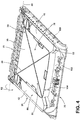
FIG. 4 is a top perspective view of a base member for the operable panel ofFIG. 2 and showing the installation of the structural foam reinforcements; -
FIG. 5 is a cross-sectional view of the appliance lid ofFIG. 2 taken along line V-V; -
FIG. 6 is a cross-sectional view of the operable panel ofFIG. 2 taken along line VI-VI; and -
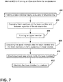
FIG. 7 is a schematic flow diagram illustrating a method for assembling an operable panel for a laundry appliance. - The components in the figures are not necessarily to scale, emphasis instead being placed upon illustrating the principles described herein.
- The present illustrated embodiments reside primarily in combinations of method steps and apparatus components related to an appliance lid having a plurality of structural foam inserts. Accordingly, the apparatus components and method steps have been represented, where appropriate, by conventional symbols in the drawings, showing only those specific details that are pertinent to understanding the embodiments of the present disclosure so as not to obscure the disclosure with details that will be readily apparent to those of ordinary skill in the art having the benefit of the description herein. Further, like numerals in the description and drawings represent like elements.
- For purposes of description herein, the terms "upper," "lower," "right," "left," "rear," "front," "vertical," "horizontal," and derivatives thereof shall relate to the disclosure as oriented in
FIG. 1 . Unless stated otherwise, the term "front" shall refer to the surface of the element closer to an intended viewer, and the term "rear" shall refer to the surface of the element further from the intended viewer. However, it is to be understood that the disclosure may assume various alternative orientations, except where expressly specified to the contrary. It is also to be understood that the specific devices and processes illustrated in the attached drawings, and described in the following specification are simply exemplary embodiments of the inventive concepts defined in the appended claims. Hence, specific dimensions and other physical characteristics relating to the embodiments disclosed herein are not to be considered as limiting, unless the claims expressly state otherwise. - The terms "including," "comprises," "comprising," or any other variation thereof, are intended to cover a non-exclusive inclusion, such that a process, method, article, or apparatus that comprises a list of elements does not include only those elements but may include other elements not expressly listed or inherent to such process, method, article, or apparatus. An element proceeded by "comprises a ... " does not, without more constraints, preclude the existence of additional identical elements in the process, method, article, or apparatus that comprises the element.
- With respect to
FIGS. 1-6 ,reference numeral 10 generally refers to an operable panel that is included within anappliance 12, typically a laundry appliance. Theoperable panel 10 can be selectively operated between anopen position 38 and a closedposition 14 to allow access within aninterior compartment 16 of thecabinet 18 for theappliance 12. As exemplified inFIG. 1 , theoperable panel 10 can be in the form of alid 20 that is positioned on atop panel 22 of thecabinet 18, such as in the form of a top-load laundry appliance. Theoperable panel 10 can also be disposed on afront panel 24 of astructural cabinet 18 for a front-load laundry appliance (not shown). In such a condition, theoperable panel 10 can be in the form of an operable door that rotationally operates with respect to thestructural cabinet 18 and the interior portions thereof. According to various aspects of the device, thelaundry appliance 12 includes a drum that rotationally operates within a tub. Acabinet 18 houses the tub and the drum and includes anaperture 26 for accessing the rotationally operable drum. Theoperable panel 10 is positioned to selectively cover theaperture 26 and enclose the tub and the drum within thecabinet 18. Theoperable panel 10, typically in the form of thelid 20, includes abase member 28 that includes a plurality ofstructural ribs 30. Anupper member 32 extends over thebase member 28 and thestructural ribs 30. Thebase member 28, thestructural ribs 30 and theupper member 32 cooperate to form a plurality ofstructural shear cavities 34 within thelid 20. A plurality offoam members 36 are positioned within a portion of theshear cavities 34 to increase the rigidity of thelid 20 as it operates between open and closedpositions - As exemplified in
FIGS. 4-6 , the plurality offoam members 36 are typically in the form of individual portions of afoam material 40 that are disposed within a portion of thestructural shear cavities 34 of thelid 20 for thelaundry appliance 12. Thefoam members 36 can be in the form of an expandable spray foam that is sprayed within the area bound by thestructural ribs 30 of thebase member 28. Theexpandable foam 42 occupies the entire space of thecorresponding shear cavity 34 that is defined within thestructural ribs 30. Accordingly, when theupper member 32 is placed on thebase member 28, theexpandable foam 42 that forms the plurality offoam members 36 is enclosed within thestructural shear cavities 34 and theexpandable foam 42 substantially occupies the entire space of thestructural shear cavities 34. - The use of the plurality of
foam members 36 provides a rigidity to thelid 20 as thelid 20 operates about arotational axis 50 between the open and closedpositions appliance 12 where certain rattling, vibration, and other motion of thelaundry appliance 12 can result in undesirable noise and vibration within thelid 20. - According to various aspects of the device, as exemplified in
FIGS. 3-6 , thelid 20 can include at least onetorsion rod 60 that extends between thebase member 28 of thelid 20 and thecabinet 18. The at least onetorsion rod 60 operates to exert abiasing force 62 on thelid 20 towards one of theopen positions 38 and the closedposition 14 and against thecabinet 18. The structural reinforcing properties of the plurality offoam members 36 cooperates with thetorsion rods 60 to prevent deflection of thelid 20 as thetorsion rods 60 bias thelid 20 in a predetermined direction. Additionally, the torsion rods 60 and the plurality offoam members 36 cooperate to minimize vibration, rattling, and other noise that may emanate from thelid 20 during operation of thelaundry appliance 12. - Typically, the
base member 28 of thelid 20 is a plastic member that is able to receive the plurality offoam members 36. Thebase member 28 can be an injection molded piece that includes thestructural ribs 30 that are integrally formed therein. Accordingly, after theexpandable foam 42 is disposed between thestructural ribs 30, thebase member 28 and the plurality offoam members 36 substantially form an integral and unitary piece as a result of adhesion between theexpandable foam 42 and the plastic material of thebase member 28. Theupper member 32 is typically a metallic member that can be fastened, latched, or otherwise secured to thebase member 28 for enclosing thestructural shear cavities 34 that contain theexpandable foam 42 in the form of thefoam members 36 within theshear cavities 34. - As exemplified in
FIGS. 1-6 , theaperture 26 of thecabinet 18 can be disposed within atop panel 22 of thecabinet 18 such that theoperable panel 10 defines alid 20 of thecabinet 18. In such an embodiment, thelid 20 is attached to thecabinet 18 via ahinge member 70 that is positioned at arear portion 72 of thelid 20. Thelid 20 can also include ahandle 74 that is positioned at afront portion 76 of thelid 20. Typically, thehandle 74 is attached to thebase member 28 and can help to secure theupper members 32 to thebase member 28. The plurality offoam members 36 that provide the structural reinforcement of thestructural shear cavities 34 are positioned distal from thehandle 74 and thehinge member 70 andtorsion rods 60. Accordingly, the plurality offoam members 36 include acentral portion 78 and opposinglateral portions 80. - According to various aspects of the device, the
central portion 78 of thefoam members 36 can be divided into a plurality of individual sections that are separated by formations ofstructural ribs 30 that extend through themedial region 90 of thebase member 28 for thelid 20. Similarly, the opposinglateral portions 80 of thefoam members 36 can also be separated by variousstructural ribs 30 that extend through thelateral regions 92 of thebase member 28 for thelid 20. In this manner, the plurality offoam members 36 that are formed throughexpandable foam 42, in combination with thestructural ribs 30, serve to reinforce thelid 20 and diminish the amount of vibration, rattling, and other noise that may occur during operation of theappliance 12 and during movement of thelid 20 between the open andclosed positions lid 20 during operation of theappliance 12 and movement of thelid 20 between the open andclosed positions force 62 exerted by thetorsion rods 60. - The opposing
lateral portions 80 of the plurality offoam members 36 can be positioned proximate theshoulder 100 of thelid 20 that is configured to engage a portion of thetop panel 22 of thecabinet 18. These shoulder portions of thebase member 28 can be a source of undesirable noise during operation of theappliance 12. Accordingly, the opposinglateral portions 80 of the plurality offoam members 36 may include a thicker section of theexpandable foam 42 to provide increased reinforcement to diminish the amount of undesirable noise that may emanate from thelid 20 during operation of theappliance 12 and operation of the door between the open andclosed positions - Additionally, the
base member 28 can include abase platform 102 that is sloped in a generally downward direction from therear portion 72 toward thefront portion 76 of thebase member 28. Accordingly, thedepth 104 of thestructural shear cavities 34 tends to increase toward thehandle 74 of thelid 20. Through this configuration, thedepth 104 of thestructural shear cavities 34 increases and the amount of theexpandable foam 42 also increases in the areas nearer thehandle 74 of thelid 20. Through this configuration, operation of thelid 20 between the open andclosed positions handle 74 of thelid 20. This is primarily because of the distance and longer moment arm between thehandle 74 and thetorsion rods 60, the source of the biasingforce 62. The thickened portions of theexpandable foam 42 that are present within acentral portion 78 and the opposinglateral portions 80 of thefoam members 36 serves to increase the structural reinforcement of thelid 20 within these areas to counteract the moment and torque-type forces that may be experienced within thelid 20, as a result of the biasingforce 62. Accordingly, each of thefoam members 36 tends to have a thinnercross-sectional depth 104 in areas nearer thetorsion rods 60 and a thickercross-sectional depth 104 within areas near thehandle 74 of thelid 20. These differences in thickness provide a balance between the overall weight of thelid 20 and the amount of structural reinforcement provided to thelid 20 through the use of theexpandable foam 42 that forms thefoam members 36 that are disposed within thestructural shear cavities 34. - Referring again to
FIGS. 1-6 , theoperable panel 10 for thelaundry appliance 12 includes thebase member 28 that includes the plurality ofstructural shear cavities 34 that are separated bystructural ribs 30. Theupper member 32 extends over thebase member 28 and theshear cavities 34. In this manner, theupper member 32 is configured to enclose at least a portion of theshear cavities 34 defined within thebase member 28. The plurality offoam members 36 includes thecentral portion 78 and opposinglateral portions 80. The plurality offoam members 36 are positioned distal from afront portion 76 and distal from arear portion 72 of thebase member 28. - In various aspects of the device, the
aperture 26 that is defined within thecabinet 18 can be positioned within afront portion 76 of thecabinet 18. In such an embodiment, theoperable panel 10 can be in the form of a rotationally operable door panel that rotates about a vertically-orientedrotational axis 50 between the open andclosed positions operable panel 10 will be in the form of alid 20 that is engaged with atop panel 22 of thestructural cabinet 18. In such an embodiment, thelid 20 rotates about a horizontally-orientedrotational axis 50 to define the open andclosed positions - Referring now to
FIGS. 1-7 , having described various aspects of theoperable panel 10 for thestructural cabinet 18, amethod 400 is disclosed for forming theoperable panel 10 for alaundry appliance 12. According to themethod 400, abase member 28 is formed that includes the plurality of structural ribs 30 (step 402). After formation of thebase member 28, anexpandable foam 42 is disposed on thebase members 28 and between portions of the structural ribs 30 (step 404). Theexpandable foam 42 forms the plurality offoam members 36 that are contained within thestructural shear cavities 34 that are defined between thestructural ribs 30 of thebase member 28. According to themethod 400, theupper member 32 is formed (step 406) and theupper member 32 is disposed onto thebase member 28 and theexpandable foam 42 to form a plurality of shear cavities 34 (step 408). According to themethod 400, at least onetorsion rod 60 can be attached to the base member 28 (step 410). As discussed previously, the at least onetorsion rod 60, typically twotorsion rods 60, are configured to exert the biasingforce 62 to bias thebase member 28 toward theclosed position 14 and against thestructural cabinet 18. According to themethod 400, thebase member 28 is attached to the cabinet 18 (step 412). Theoperable panel 10 is selectively operable relative to thecabinet 18 between the open andclosed positions - In certain aspects of the device, the
torsion rods 60 can also exert the biasingforce 62 in an upward direction and toward theopen position 38. This upward biasingforce 62 can be used to assist the user in lifting thelid 20 to theopen position 38. In this configuration, thetorsion rods 60 are used as a power assist mechanism to help the user lift thelid 20 to theopen position 38 and also prevent thelid 20 from impacting thetop panel 22 at a force of gravity or greater when moved toward theclosed position 14. - According to various aspects of the device, the use of the
expandable foam 42 that is disposed within thestructural shear cavities 34 is intended to increase the rigidity and overall structural integrity of theoperable panel 10. The increased rigidity of thelid 20 serves to limit the amount of vibration, rattling, and other undesirable noise during operation of theappliance 12. Additionally, the use of theexpandable foam 42 contained within thestructural shear cavities 34 limits the amount of deflection that is experienced by thelid 20. This is particularly true as the torsion members bias thelid 20 toward theclosed position 14, or theopen position 38, and during operation of thelid 20 to theopen position 38. Necessarily, movement of thelid 20 in a certain direction counteracts a biasingforce 62 exerted by thetorsion rods 60 that biases thelid 20 toward one of theopen position 38 and theclosed position 14. These moment and torque-type forces are structurally accounted for through the incorporation of thestructural shear cavities 34 having theexpandable foam 42 incorporated therein. - It should be understood that the use of the
expandable foam 42 within thestructural shear cavities 34 of theoperable panel 10 can be incorporated within a variety ofoperable panels 10 for a range ofappliances 12.Such appliances 12 can include, but are not limited to, dishwashers, ovens, refrigerating appliances, countertop appliances, small appliances, and other similar household and commercial appliances and fixtures.
Claims (15)
- A laundry appliance (12) comprising:a drum that rotationally operates within a tub;a cabinet (18) that houses the tub and the drum and having an aperture (26) for accessing the drum;an operable panel (10) that selectively covers the aperture (26), the operable panel (10) comprising:a base member (28) that includes a plurality of structural ribs (30);an upper member (32) that extends over the base member (28) and the structural ribs (30), wherein the base member (28), the structural ribs (30) and the upper member (32) cooperate to form a plurality of structural shear cavities (34); anda plurality of foam members (36) that are positioned within a portion of the shear cavities (34) to increase rigidity of the operable panel (10).
- The laundry appliance (12) of claim 1, further comprising at least one torsion rod (60) that extends from the base member (28) to the cabinet (18), wherein the torsion rod (60) biases the operable panel (10) toward a closed position (14).
- The laundry appliance (12) of any one or more of claims 1-2, wherein the operable panel (10) is attached to the cabinet (18) via a hinge member (70).
- The laundry appliance (12) of any one or more of claims 1-3, wherein the base member (28) is plastic.
- The laundry appliance (12) of any one or more of claims 1-4, wherein the upper member (32) is metallic.
- The laundry appliance (12) of any one or more of claims 1-5, wherein the aperture (26) is on a top panel (22) of the cabinet (18) and the operable panel (10) defines a lid (20) of the cabinet (18).
- The laundry appliance (12) of any one or more of claims 2-6, wherein the plurality of foam members (36) are positioned distal from a handle (74) and distal from the at least one torsion rod (60).
- The laundry appliance (12) of any one or more of claims 1-7, wherein the plurality of foam members (36) includes a central portion (78) and opposing lateral portions (80).
- The laundry appliance (12) of any one or more of claims 1-8, wherein the operable panel (10) is a rotationally operable door panel.
- The laundry appliance (12) of any one or more of claims 1-9, wherein the at least one torsion rod (60) is positioned within a rear portion (72) of the base member (28).
- The laundry appliance (12) of any one or more of claims 1-10, wherein the operable panel (10) is a lid (20) for a top-load laundry appliance (12).
- The laundry appliance (12) of any one or more of claims 1-11, wherein the plurality of foam members (36) are positioned distal from a front portion (76) and distal from a rear portion (72) of the base member (28).
- The laundry appliance (12) of claim 12, wherein the base member (28) includes a base platform (102) that tapers away from the upper member (32) in a direction toward the front portion (76).
- The operable panel (10) of any one or more of claims 1-13, wherein the foam members (36) include an expandable foam material (40).
- A method for forming the operable panel (10) for the laundry appliance (12) of any of claims 1-14 comprising:forming the base member (28) having the plurality of structural ribs (30);disposing the plurality of foam members (36) on the base member (28) and between a portion of the plurality of structural ribs (30);forming the upper member (32); anddisposing the upper member (32) onto the base member (28) and the plurality of foam members (36) to form the plurality of shear cavities (34).
Applications Claiming Priority (1)
| Application Number | Priority Date | Filing Date | Title |
|---|---|---|---|
| US16/587,708 US11492748B2 (en) | 2019-09-30 | 2019-09-30 | Appliance lid that incorporates interior structural foam reinforcement |
Publications (2)
| Publication Number | Publication Date |
|---|---|
| EP3798351A1 true EP3798351A1 (en) | 2021-03-31 |
| EP3798351B1 EP3798351B1 (en) | 2022-07-27 |
Family
ID=72659083
Family Applications (1)
| Application Number | Title | Priority Date | Filing Date |
|---|---|---|---|
| EP20198253.5A Active EP3798351B1 (en) | 2019-09-30 | 2020-09-24 | Appliance lid that incorporates interior structural foam reinforcement |
Country Status (2)
| Country | Link |
|---|---|
| US (2) | US11492748B2 (en) |
| EP (1) | EP3798351B1 (en) |
Cited By (1)
| Publication number | Priority date | Publication date | Assignee | Title |
|---|---|---|---|---|
| EP4471203A1 (en) * | 2023-05-30 | 2024-12-04 | Gorenje Gospodinjski Aparati, d.o.o. | Household appliance with a cover pane |
Citations (5)
| Publication number | Priority date | Publication date | Assignee | Title |
|---|---|---|---|---|
| US3323224A (en) * | 1964-06-08 | 1967-06-06 | Whirlpool Co | Lint accumulator means for a dryer |
| KR20010001088A (en) * | 1999-06-01 | 2001-01-05 | 구자홍 | Full automatic washing machine |
| JP2003265892A (en) * | 2002-03-13 | 2003-09-24 | Sekisui Chem Co Ltd | Soundproofing equipment for home appliances |
| KR20100065846A (en) * | 2008-12-09 | 2010-06-17 | 삼성전자주식회사 | Washing machine and door of washing machine |
| EP3450613A1 (en) * | 2017-09-01 | 2019-03-06 | Whirlpool Corporation | Rear panel and basement damping treatments for a laundry appliance |
Family Cites Families (11)
| Publication number | Priority date | Publication date | Assignee | Title |
|---|---|---|---|---|
| GB9122079D0 (en) | 1991-10-17 | 1991-11-27 | J E S Arnold Domestic Applianc | A door for a domestic electrical appliance |
| DE10208065A1 (en) | 2002-02-25 | 2003-09-04 | Bsh Bosch Siemens Hausgeraete | Housings for a household appliance |
| JP2004188172A (en) | 2002-10-17 | 2004-07-08 | Sanyo Electric Co Ltd | Method of fixing outer tub in drum washing machine |
| EP1640494B1 (en) | 2004-09-22 | 2008-11-19 | Electrolux Home Products Corporation N.V. | Improvement in the lid of a top-loading clothes washing machine |
| KR101461941B1 (en) * | 2008-02-12 | 2014-11-14 | 엘지전자 주식회사 | Laundry processing device |
| JP4900395B2 (en) * | 2009-01-21 | 2012-03-21 | パナソニック株式会社 | Washing machine lid structure |
| US8015848B2 (en) | 2009-01-22 | 2011-09-13 | Electrolux Home Products, Inc. | Acoustic panel |
| EP2554735B1 (en) | 2011-08-02 | 2020-04-22 | Electrolux Home Products Corporation N.V. | A top-loading washing machine comprising a pivoting lid |
| US9920466B2 (en) * | 2015-02-24 | 2018-03-20 | Clarion Technologies, Inc. | Structural foam-core panels |
| KR102418217B1 (en) * | 2015-08-26 | 2022-07-08 | 삼성전자주식회사 | Washing machine |
| PL3323927T3 (en) | 2016-11-21 | 2022-04-19 | Electrolux Appliances Aktiebolag | A door assembly for a laundry treating machine |
-
2019
- 2019-09-30 US US16/587,708 patent/US11492748B2/en active Active
-
2020
- 2020-09-24 EP EP20198253.5A patent/EP3798351B1/en active Active
-
2022
- 2022-10-04 US US17/959,354 patent/US20230026129A1/en not_active Abandoned
Patent Citations (5)
| Publication number | Priority date | Publication date | Assignee | Title |
|---|---|---|---|---|
| US3323224A (en) * | 1964-06-08 | 1967-06-06 | Whirlpool Co | Lint accumulator means for a dryer |
| KR20010001088A (en) * | 1999-06-01 | 2001-01-05 | 구자홍 | Full automatic washing machine |
| JP2003265892A (en) * | 2002-03-13 | 2003-09-24 | Sekisui Chem Co Ltd | Soundproofing equipment for home appliances |
| KR20100065846A (en) * | 2008-12-09 | 2010-06-17 | 삼성전자주식회사 | Washing machine and door of washing machine |
| EP3450613A1 (en) * | 2017-09-01 | 2019-03-06 | Whirlpool Corporation | Rear panel and basement damping treatments for a laundry appliance |
Cited By (1)
| Publication number | Priority date | Publication date | Assignee | Title |
|---|---|---|---|---|
| EP4471203A1 (en) * | 2023-05-30 | 2024-12-04 | Gorenje Gospodinjski Aparati, d.o.o. | Household appliance with a cover pane |
Also Published As
| Publication number | Publication date |
|---|---|
| EP3798351B1 (en) | 2022-07-27 |
| US20210095414A1 (en) | 2021-04-01 |
| US11492748B2 (en) | 2022-11-08 |
| US20230026129A1 (en) | 2023-01-26 |
Similar Documents
| Publication | Publication Date | Title |
|---|---|---|
| US10317128B2 (en) | Refrigerator | |
| US20020008448A1 (en) | Cabinet for washing machine | |
| EP2785907B1 (en) | Household electrical appliance and loading door for such appliance | |
| TW201733881A (en) | Receptacle assemblies with motion dampers | |
| EP3798351B1 (en) | Appliance lid that incorporates interior structural foam reinforcement | |
| US10422070B2 (en) | Laundry treating appliance and dispenser | |
| US2877077A (en) | Refrigerator door with trays | |
| KR102344968B1 (en) | Opening and Closing Structure of Trash Tousseng equipped with a switchgear. | |
| KR20190128421A (en) | Refrigerator | |
| US9649916B2 (en) | Door trim panel for energy absorption | |
| AU2010246375B2 (en) | Appliance Lid And Assembly | |
| US20050103064A1 (en) | Washing machine | |
| WO1998005908A1 (en) | Door handle structure in refrigerators | |
| KR101962133B1 (en) | Top loading washing machine | |
| EP0744521B1 (en) | Hinge with movable axis of rotation in particular for the panel-finished doors of built-in dish washing machines | |
| US20180073184A1 (en) | Laundry treating appliance and dispenser | |
| KR102512219B1 (en) | Dish washer | |
| KR20220085383A (en) | Refrigerator | |
| KR20060036539A (en) | Drum Washing Machine with Bottom Open Door | |
| JP3666101B2 (en) | Hinge device for refrigerator and method for processing hinge device | |
| KR20240136532A (en) | Refrigerator | |
| TWI816274B (en) | Refrigerator | |
| KR102338782B1 (en) | Refrigerator | |
| KR100707428B1 (en) | Case of drum washer | |
| EP4202330B1 (en) | Refrigerator |
Legal Events
| Date | Code | Title | Description |
|---|---|---|---|
| PUAI | Public reference made under article 153(3) epc to a published international application that has entered the european phase |
Free format text: ORIGINAL CODE: 0009012 |
|
| STAA | Information on the status of an ep patent application or granted ep patent |
Free format text: STATUS: THE APPLICATION HAS BEEN PUBLISHED |
|
| AK | Designated contracting states |
Kind code of ref document: A1 Designated state(s): AL AT BE BG CH CY CZ DE DK EE ES FI FR GB GR HR HU IE IS IT LI LT LU LV MC MK MT NL NO PL PT RO RS SE SI SK SM TR |
|
| AX | Request for extension of the european patent |
Extension state: BA ME |
|
| STAA | Information on the status of an ep patent application or granted ep patent |
Free format text: STATUS: REQUEST FOR EXAMINATION WAS MADE |
|
| 17P | Request for examination filed |
Effective date: 20210907 |
|
| RBV | Designated contracting states (corrected) |
Designated state(s): AL AT BE BG CH CY CZ DE DK EE ES FI FR GB GR HR HU IE IS IT LI LT LU LV MC MK MT NL NO PL PT RO RS SE SI SK SM TR |
|
| GRAP | Despatch of communication of intention to grant a patent |
Free format text: ORIGINAL CODE: EPIDOSNIGR1 |
|
| STAA | Information on the status of an ep patent application or granted ep patent |
Free format text: STATUS: GRANT OF PATENT IS INTENDED |
|
| INTG | Intention to grant announced |
Effective date: 20220329 |
|
| GRAJ | Information related to disapproval of communication of intention to grant by the applicant or resumption of examination proceedings by the epo deleted |
Free format text: ORIGINAL CODE: EPIDOSDIGR1 |
|
| STAA | Information on the status of an ep patent application or granted ep patent |
Free format text: STATUS: REQUEST FOR EXAMINATION WAS MADE |
|
| INTC | Intention to grant announced (deleted) | ||
| GRAP | Despatch of communication of intention to grant a patent |
Free format text: ORIGINAL CODE: EPIDOSNIGR1 |
|
| STAA | Information on the status of an ep patent application or granted ep patent |
Free format text: STATUS: GRANT OF PATENT IS INTENDED |
|
| GRAS | Grant fee paid |
Free format text: ORIGINAL CODE: EPIDOSNIGR3 |
|
| GRAA | (expected) grant |
Free format text: ORIGINAL CODE: 0009210 |
|
| STAA | Information on the status of an ep patent application or granted ep patent |
Free format text: STATUS: THE PATENT HAS BEEN GRANTED |
|
| INTG | Intention to grant announced |
Effective date: 20220607 |
|
| AK | Designated contracting states |
Kind code of ref document: B1 Designated state(s): AL AT BE BG CH CY CZ DE DK EE ES FI FR GB GR HR HU IE IS IT LI LT LU LV MC MK MT NL NO PL PT RO RS SE SI SK SM TR |
|
| REG | Reference to a national code |
Ref country code: CH Ref legal event code: EP |
|
| REG | Reference to a national code |
Ref country code: DE Ref legal event code: R096 Ref document number: 602020004189 Country of ref document: DE |
|
| REG | Reference to a national code |
Ref country code: AT Ref legal event code: REF Ref document number: 1507148 Country of ref document: AT Kind code of ref document: T Effective date: 20220815 |
|
| REG | Reference to a national code |
Ref country code: IE Ref legal event code: FG4D |
|
| REG | Reference to a national code |
Ref country code: LT Ref legal event code: MG9D |
|
| REG | Reference to a national code |
Ref country code: NL Ref legal event code: MP Effective date: 20220727 |
|
| PG25 | Lapsed in a contracting state [announced via postgrant information from national office to epo] |
Ref country code: SE Free format text: LAPSE BECAUSE OF FAILURE TO SUBMIT A TRANSLATION OF THE DESCRIPTION OR TO PAY THE FEE WITHIN THE PRESCRIBED TIME-LIMIT Effective date: 20220727 Ref country code: RS Free format text: LAPSE BECAUSE OF FAILURE TO SUBMIT A TRANSLATION OF THE DESCRIPTION OR TO PAY THE FEE WITHIN THE PRESCRIBED TIME-LIMIT Effective date: 20220727 Ref country code: PT Free format text: LAPSE BECAUSE OF FAILURE TO SUBMIT A TRANSLATION OF THE DESCRIPTION OR TO PAY THE FEE WITHIN THE PRESCRIBED TIME-LIMIT Effective date: 20221128 Ref country code: NO Free format text: LAPSE BECAUSE OF FAILURE TO SUBMIT A TRANSLATION OF THE DESCRIPTION OR TO PAY THE FEE WITHIN THE PRESCRIBED TIME-LIMIT Effective date: 20221027 Ref country code: NL Free format text: LAPSE BECAUSE OF FAILURE TO SUBMIT A TRANSLATION OF THE DESCRIPTION OR TO PAY THE FEE WITHIN THE PRESCRIBED TIME-LIMIT Effective date: 20220727 Ref country code: LV Free format text: LAPSE BECAUSE OF FAILURE TO SUBMIT A TRANSLATION OF THE DESCRIPTION OR TO PAY THE FEE WITHIN THE PRESCRIBED TIME-LIMIT Effective date: 20220727 Ref country code: LT Free format text: LAPSE BECAUSE OF FAILURE TO SUBMIT A TRANSLATION OF THE DESCRIPTION OR TO PAY THE FEE WITHIN THE PRESCRIBED TIME-LIMIT Effective date: 20220727 Ref country code: FI Free format text: LAPSE BECAUSE OF FAILURE TO SUBMIT A TRANSLATION OF THE DESCRIPTION OR TO PAY THE FEE WITHIN THE PRESCRIBED TIME-LIMIT Effective date: 20220727 Ref country code: ES Free format text: LAPSE BECAUSE OF FAILURE TO SUBMIT A TRANSLATION OF THE DESCRIPTION OR TO PAY THE FEE WITHIN THE PRESCRIBED TIME-LIMIT Effective date: 20220727 |
|
| REG | Reference to a national code |
Ref country code: AT Ref legal event code: MK05 Ref document number: 1507148 Country of ref document: AT Kind code of ref document: T Effective date: 20220727 |
|
| PG25 | Lapsed in a contracting state [announced via postgrant information from national office to epo] |
Ref country code: PL Free format text: LAPSE BECAUSE OF FAILURE TO SUBMIT A TRANSLATION OF THE DESCRIPTION OR TO PAY THE FEE WITHIN THE PRESCRIBED TIME-LIMIT Effective date: 20220727 Ref country code: IS Free format text: LAPSE BECAUSE OF FAILURE TO SUBMIT A TRANSLATION OF THE DESCRIPTION OR TO PAY THE FEE WITHIN THE PRESCRIBED TIME-LIMIT Effective date: 20221127 Ref country code: HR Free format text: LAPSE BECAUSE OF FAILURE TO SUBMIT A TRANSLATION OF THE DESCRIPTION OR TO PAY THE FEE WITHIN THE PRESCRIBED TIME-LIMIT Effective date: 20220727 Ref country code: GR Free format text: LAPSE BECAUSE OF FAILURE TO SUBMIT A TRANSLATION OF THE DESCRIPTION OR TO PAY THE FEE WITHIN THE PRESCRIBED TIME-LIMIT Effective date: 20221028 |
|
| PG25 | Lapsed in a contracting state [announced via postgrant information from national office to epo] |
Ref country code: SM Free format text: LAPSE BECAUSE OF FAILURE TO SUBMIT A TRANSLATION OF THE DESCRIPTION OR TO PAY THE FEE WITHIN THE PRESCRIBED TIME-LIMIT Effective date: 20220727 Ref country code: RO Free format text: LAPSE BECAUSE OF FAILURE TO SUBMIT A TRANSLATION OF THE DESCRIPTION OR TO PAY THE FEE WITHIN THE PRESCRIBED TIME-LIMIT Effective date: 20220727 Ref country code: MC Free format text: LAPSE BECAUSE OF FAILURE TO SUBMIT A TRANSLATION OF THE DESCRIPTION OR TO PAY THE FEE WITHIN THE PRESCRIBED TIME-LIMIT Effective date: 20220727 Ref country code: DK Free format text: LAPSE BECAUSE OF FAILURE TO SUBMIT A TRANSLATION OF THE DESCRIPTION OR TO PAY THE FEE WITHIN THE PRESCRIBED TIME-LIMIT Effective date: 20220727 Ref country code: CZ Free format text: LAPSE BECAUSE OF FAILURE TO SUBMIT A TRANSLATION OF THE DESCRIPTION OR TO PAY THE FEE WITHIN THE PRESCRIBED TIME-LIMIT Effective date: 20220727 Ref country code: AT Free format text: LAPSE BECAUSE OF FAILURE TO SUBMIT A TRANSLATION OF THE DESCRIPTION OR TO PAY THE FEE WITHIN THE PRESCRIBED TIME-LIMIT Effective date: 20220727 |
|
| REG | Reference to a national code |
Ref country code: DE Ref legal event code: R097 Ref document number: 602020004189 Country of ref document: DE |
|
| REG | Reference to a national code |
Ref country code: BE Ref legal event code: MM Effective date: 20220930 |
|
| PG25 | Lapsed in a contracting state [announced via postgrant information from national office to epo] |
Ref country code: SK Free format text: LAPSE BECAUSE OF FAILURE TO SUBMIT A TRANSLATION OF THE DESCRIPTION OR TO PAY THE FEE WITHIN THE PRESCRIBED TIME-LIMIT Effective date: 20220727 Ref country code: EE Free format text: LAPSE BECAUSE OF FAILURE TO SUBMIT A TRANSLATION OF THE DESCRIPTION OR TO PAY THE FEE WITHIN THE PRESCRIBED TIME-LIMIT Effective date: 20220727 |
|
| PLBE | No opposition filed within time limit |
Free format text: ORIGINAL CODE: 0009261 |
|
| STAA | Information on the status of an ep patent application or granted ep patent |
Free format text: STATUS: NO OPPOSITION FILED WITHIN TIME LIMIT |
|
| P01 | Opt-out of the competence of the unified patent court (upc) registered |
Effective date: 20230523 |
|
| PG25 | Lapsed in a contracting state [announced via postgrant information from national office to epo] |
Ref country code: LU Free format text: LAPSE BECAUSE OF NON-PAYMENT OF DUE FEES Effective date: 20220924 Ref country code: AL Free format text: LAPSE BECAUSE OF FAILURE TO SUBMIT A TRANSLATION OF THE DESCRIPTION OR TO PAY THE FEE WITHIN THE PRESCRIBED TIME-LIMIT Effective date: 20220727 |
|
| 26N | No opposition filed |
Effective date: 20230502 |
|
| PG25 | Lapsed in a contracting state [announced via postgrant information from national office to epo] |
Ref country code: IE Free format text: LAPSE BECAUSE OF NON-PAYMENT OF DUE FEES Effective date: 20220924 |
|
| PG25 | Lapsed in a contracting state [announced via postgrant information from national office to epo] |
Ref country code: SI Free format text: LAPSE BECAUSE OF FAILURE TO SUBMIT A TRANSLATION OF THE DESCRIPTION OR TO PAY THE FEE WITHIN THE PRESCRIBED TIME-LIMIT Effective date: 20220727 |
|
| PG25 | Lapsed in a contracting state [announced via postgrant information from national office to epo] |
Ref country code: BE Free format text: LAPSE BECAUSE OF NON-PAYMENT OF DUE FEES Effective date: 20220930 |
|
| PG25 | Lapsed in a contracting state [announced via postgrant information from national office to epo] |
Ref country code: CY Free format text: LAPSE BECAUSE OF FAILURE TO SUBMIT A TRANSLATION OF THE DESCRIPTION OR TO PAY THE FEE WITHIN THE PRESCRIBED TIME-LIMIT Effective date: 20220727 |
|
| REG | Reference to a national code |
Ref country code: CH Ref legal event code: PL |
|
| PG25 | Lapsed in a contracting state [announced via postgrant information from national office to epo] |
Ref country code: MK Free format text: LAPSE BECAUSE OF FAILURE TO SUBMIT A TRANSLATION OF THE DESCRIPTION OR TO PAY THE FEE WITHIN THE PRESCRIBED TIME-LIMIT Effective date: 20220727 |
|
| PG25 | Lapsed in a contracting state [announced via postgrant information from national office to epo] |
Ref country code: TR Free format text: LAPSE BECAUSE OF FAILURE TO SUBMIT A TRANSLATION OF THE DESCRIPTION OR TO PAY THE FEE WITHIN THE PRESCRIBED TIME-LIMIT Effective date: 20220727 |
|
| PG25 | Lapsed in a contracting state [announced via postgrant information from national office to epo] |
Ref country code: CH Free format text: LAPSE BECAUSE OF NON-PAYMENT OF DUE FEES Effective date: 20230930 |
|
| PG25 | Lapsed in a contracting state [announced via postgrant information from national office to epo] |
Ref country code: HU Free format text: LAPSE BECAUSE OF FAILURE TO SUBMIT A TRANSLATION OF THE DESCRIPTION OR TO PAY THE FEE WITHIN THE PRESCRIBED TIME-LIMIT; INVALID AB INITIO Effective date: 20200924 Ref country code: CH Free format text: LAPSE BECAUSE OF NON-PAYMENT OF DUE FEES Effective date: 20230930 Ref country code: BG Free format text: LAPSE BECAUSE OF FAILURE TO SUBMIT A TRANSLATION OF THE DESCRIPTION OR TO PAY THE FEE WITHIN THE PRESCRIBED TIME-LIMIT Effective date: 20220727 |
|
| PG25 | Lapsed in a contracting state [announced via postgrant information from national office to epo] |
Ref country code: MT Free format text: LAPSE BECAUSE OF FAILURE TO SUBMIT A TRANSLATION OF THE DESCRIPTION OR TO PAY THE FEE WITHIN THE PRESCRIBED TIME-LIMIT Effective date: 20220727 |
|
| PGFP | Annual fee paid to national office [announced via postgrant information from national office to epo] |
Ref country code: DE Payment date: 20250926 Year of fee payment: 6 |
|
| PGFP | Annual fee paid to national office [announced via postgrant information from national office to epo] |
Ref country code: IT Payment date: 20250908 Year of fee payment: 6 |
|
| PGFP | Annual fee paid to national office [announced via postgrant information from national office to epo] |
Ref country code: GB Payment date: 20250923 Year of fee payment: 6 |
|
| PGFP | Annual fee paid to national office [announced via postgrant information from national office to epo] |
Ref country code: FR Payment date: 20250925 Year of fee payment: 6 |