EP3798135A1 - Assembling device - Google Patents
Assembling device Download PDFInfo
- Publication number
- EP3798135A1 EP3798135A1 EP20192968.4A EP20192968A EP3798135A1 EP 3798135 A1 EP3798135 A1 EP 3798135A1 EP 20192968 A EP20192968 A EP 20192968A EP 3798135 A1 EP3798135 A1 EP 3798135A1
- Authority
- EP
- European Patent Office
- Prior art keywords
- excess thickness
- rib
- assembly
- thickness portion
- portions
- Prior art date
- Legal status (The legal status is an assumption and is not a legal conclusion. Google has not performed a legal analysis and makes no representation as to the accuracy of the status listed.)
- Granted
Links
Images

Classifications
-
- B—PERFORMING OPERATIONS; TRANSPORTING
- B23—MACHINE TOOLS; METAL-WORKING NOT OTHERWISE PROVIDED FOR
- B23P—METAL-WORKING NOT OTHERWISE PROVIDED FOR; COMBINED OPERATIONS; UNIVERSAL MACHINE TOOLS
- B23P19/00—Machines for simply fitting together or separating metal parts or objects, or metal and non-metal parts, whether or not involving some deformation; Tools or devices therefor so far as not provided for in other classes
- B23P19/04—Machines for simply fitting together or separating metal parts or objects, or metal and non-metal parts, whether or not involving some deformation; Tools or devices therefor so far as not provided for in other classes for assembling or disassembling parts
-
- B—PERFORMING OPERATIONS; TRANSPORTING
- B64—AIRCRAFT; AVIATION; COSMONAUTICS
- B64F—GROUND OR AIRCRAFT-CARRIER-DECK INSTALLATIONS SPECIALLY ADAPTED FOR USE IN CONNECTION WITH AIRCRAFT; DESIGNING, MANUFACTURING, ASSEMBLING, CLEANING, MAINTAINING OR REPAIRING AIRCRAFT, NOT OTHERWISE PROVIDED FOR; HANDLING, TRANSPORTING, TESTING OR INSPECTING AIRCRAFT COMPONENTS, NOT OTHERWISE PROVIDED FOR
- B64F5/00—Designing, manufacturing, assembling, cleaning, maintaining or repairing aircraft, not otherwise provided for; Handling, transporting, testing or inspecting aircraft components, not otherwise provided for
- B64F5/10—Manufacturing or assembling aircraft, e.g. jigs therefor
-
- B—PERFORMING OPERATIONS; TRANSPORTING
- B23—MACHINE TOOLS; METAL-WORKING NOT OTHERWISE PROVIDED FOR
- B23P—METAL-WORKING NOT OTHERWISE PROVIDED FOR; COMBINED OPERATIONS; UNIVERSAL MACHINE TOOLS
- B23P17/00—Metal-working operations, not covered by a single other subclass or another group in this subclass
- B23P17/02—Single metal-working processes; Machines or apparatus therefor
-
- B—PERFORMING OPERATIONS; TRANSPORTING
- B25—HAND TOOLS; PORTABLE POWER-DRIVEN TOOLS; MANIPULATORS
- B25J—MANIPULATORS; CHAMBERS PROVIDED WITH MANIPULATION DEVICES
- B25J11/00—Manipulators not otherwise provided for
- B25J11/005—Manipulators for mechanical processing tasks
-
- B—PERFORMING OPERATIONS; TRANSPORTING
- B23—MACHINE TOOLS; METAL-WORKING NOT OTHERWISE PROVIDED FOR
- B23P—METAL-WORKING NOT OTHERWISE PROVIDED FOR; COMBINED OPERATIONS; UNIVERSAL MACHINE TOOLS
- B23P13/00—Making metal objects by operations essentially involving machining but not covered by a single other subclass
-
- B—PERFORMING OPERATIONS; TRANSPORTING
- B23—MACHINE TOOLS; METAL-WORKING NOT OTHERWISE PROVIDED FOR
- B23P—METAL-WORKING NOT OTHERWISE PROVIDED FOR; COMBINED OPERATIONS; UNIVERSAL MACHINE TOOLS
- B23P2700/00—Indexing scheme relating to the articles being treated, e.g. manufactured, repaired, assembled, connected or other operations covered in the subgroups
- B23P2700/01—Aircraft parts
-
- B—PERFORMING OPERATIONS; TRANSPORTING
- B25—HAND TOOLS; PORTABLE POWER-DRIVEN TOOLS; MANIPULATORS
- B25J—MANIPULATORS; CHAMBERS PROVIDED WITH MANIPULATION DEVICES
- B25J11/00—Manipulators not otherwise provided for
- B25J11/005—Manipulators for mechanical processing tasks
- B25J11/0055—Cutting
-
- Y—GENERAL TAGGING OF NEW TECHNOLOGICAL DEVELOPMENTS; GENERAL TAGGING OF CROSS-SECTIONAL TECHNOLOGIES SPANNING OVER SEVERAL SECTIONS OF THE IPC; TECHNICAL SUBJECTS COVERED BY FORMER USPC CROSS-REFERENCE ART COLLECTIONS [XRACs] AND DIGESTS
- Y10—TECHNICAL SUBJECTS COVERED BY FORMER USPC
- Y10T—TECHNICAL SUBJECTS COVERED BY FORMER US CLASSIFICATION
- Y10T29/00—Metal working
- Y10T29/49—Method of mechanical manufacture
- Y10T29/49718—Repairing
- Y10T29/49721—Repairing with disassembling
- Y10T29/49723—Repairing with disassembling including reconditioning of part
- Y10T29/49725—Repairing with disassembling including reconditioning of part by shaping
- Y10T29/49726—Removing material
-
- Y—GENERAL TAGGING OF NEW TECHNOLOGICAL DEVELOPMENTS; GENERAL TAGGING OF CROSS-SECTIONAL TECHNOLOGIES SPANNING OVER SEVERAL SECTIONS OF THE IPC; TECHNICAL SUBJECTS COVERED BY FORMER USPC CROSS-REFERENCE ART COLLECTIONS [XRACs] AND DIGESTS
- Y10—TECHNICAL SUBJECTS COVERED BY FORMER USPC
- Y10T—TECHNICAL SUBJECTS COVERED BY FORMER US CLASSIFICATION
- Y10T29/00—Metal working
- Y10T29/49—Method of mechanical manufacture
- Y10T29/49718—Repairing
- Y10T29/49748—Repairing by shaping, e.g., bending, extruding, turning, etc.
-
- Y—GENERAL TAGGING OF NEW TECHNOLOGICAL DEVELOPMENTS; GENERAL TAGGING OF CROSS-SECTIONAL TECHNOLOGIES SPANNING OVER SEVERAL SECTIONS OF THE IPC; TECHNICAL SUBJECTS COVERED BY FORMER USPC CROSS-REFERENCE ART COLLECTIONS [XRACs] AND DIGESTS
- Y10—TECHNICAL SUBJECTS COVERED BY FORMER USPC
- Y10T—TECHNICAL SUBJECTS COVERED BY FORMER US CLASSIFICATION
- Y10T29/00—Metal working
- Y10T29/49—Method of mechanical manufacture
- Y10T29/49762—Center locating and shaping
-
- Y—GENERAL TAGGING OF NEW TECHNOLOGICAL DEVELOPMENTS; GENERAL TAGGING OF CROSS-SECTIONAL TECHNOLOGIES SPANNING OVER SEVERAL SECTIONS OF THE IPC; TECHNICAL SUBJECTS COVERED BY FORMER USPC CROSS-REFERENCE ART COLLECTIONS [XRACs] AND DIGESTS
- Y10—TECHNICAL SUBJECTS COVERED BY FORMER USPC
- Y10T—TECHNICAL SUBJECTS COVERED BY FORMER US CLASSIFICATION
- Y10T29/00—Metal working
- Y10T29/49—Method of mechanical manufacture
- Y10T29/49813—Shaping mating parts for reassembly in different positions
-
- Y—GENERAL TAGGING OF NEW TECHNOLOGICAL DEVELOPMENTS; GENERAL TAGGING OF CROSS-SECTIONAL TECHNOLOGIES SPANNING OVER SEVERAL SECTIONS OF THE IPC; TECHNICAL SUBJECTS COVERED BY FORMER USPC CROSS-REFERENCE ART COLLECTIONS [XRACs] AND DIGESTS
- Y10—TECHNICAL SUBJECTS COVERED BY FORMER USPC
- Y10T—TECHNICAL SUBJECTS COVERED BY FORMER US CLASSIFICATION
- Y10T29/00—Metal working
- Y10T29/49—Method of mechanical manufacture
- Y10T29/49826—Assembling or joining
- Y10T29/49861—Sizing mating parts during final positional association
-
- Y—GENERAL TAGGING OF NEW TECHNOLOGICAL DEVELOPMENTS; GENERAL TAGGING OF CROSS-SECTIONAL TECHNOLOGIES SPANNING OVER SEVERAL SECTIONS OF THE IPC; TECHNICAL SUBJECTS COVERED BY FORMER USPC CROSS-REFERENCE ART COLLECTIONS [XRACs] AND DIGESTS
- Y10—TECHNICAL SUBJECTS COVERED BY FORMER USPC
- Y10T—TECHNICAL SUBJECTS COVERED BY FORMER US CLASSIFICATION
- Y10T29/00—Metal working
- Y10T29/49—Method of mechanical manufacture
- Y10T29/49826—Assembling or joining
- Y10T29/49895—Associating parts by use of aligning means [e.g., use of a drift pin or a "fixture"]
-
- Y—GENERAL TAGGING OF NEW TECHNOLOGICAL DEVELOPMENTS; GENERAL TAGGING OF CROSS-SECTIONAL TECHNOLOGIES SPANNING OVER SEVERAL SECTIONS OF THE IPC; TECHNICAL SUBJECTS COVERED BY FORMER USPC CROSS-REFERENCE ART COLLECTIONS [XRACs] AND DIGESTS
- Y10—TECHNICAL SUBJECTS COVERED BY FORMER USPC
- Y10T—TECHNICAL SUBJECTS COVERED BY FORMER US CLASSIFICATION
- Y10T29/00—Metal working
- Y10T29/49—Method of mechanical manufacture
- Y10T29/49995—Shaping one-piece blank by removing material
- Y10T29/49996—Successive distinct removal operations
-
- Y—GENERAL TAGGING OF NEW TECHNOLOGICAL DEVELOPMENTS; GENERAL TAGGING OF CROSS-SECTIONAL TECHNOLOGIES SPANNING OVER SEVERAL SECTIONS OF THE IPC; TECHNICAL SUBJECTS COVERED BY FORMER USPC CROSS-REFERENCE ART COLLECTIONS [XRACs] AND DIGESTS
- Y10—TECHNICAL SUBJECTS COVERED BY FORMER USPC
- Y10T—TECHNICAL SUBJECTS COVERED BY FORMER US CLASSIFICATION
- Y10T29/00—Metal working
- Y10T29/49—Method of mechanical manufacture
- Y10T29/49998—Work holding
-
- Y—GENERAL TAGGING OF NEW TECHNOLOGICAL DEVELOPMENTS; GENERAL TAGGING OF CROSS-SECTIONAL TECHNOLOGIES SPANNING OVER SEVERAL SECTIONS OF THE IPC; TECHNICAL SUBJECTS COVERED BY FORMER USPC CROSS-REFERENCE ART COLLECTIONS [XRACs] AND DIGESTS
- Y10—TECHNICAL SUBJECTS COVERED BY FORMER USPC
- Y10T—TECHNICAL SUBJECTS COVERED BY FORMER US CLASSIFICATION
- Y10T29/00—Metal working
- Y10T29/51—Plural diverse manufacturing apparatus including means for metal shaping or assembling
- Y10T29/5136—Separate tool stations for selective or successive operation on work
- Y10T29/5137—Separate tool stations for selective or successive operation on work including assembling or disassembling station
- Y10T29/5138—Separate tool stations for selective or successive operation on work including assembling or disassembling station and means to machine work part to fit cooperating work part
Definitions
- the invention relates to an assembling device.
- Japanese Unexamined Patent Application Publication JP 2016-192 237 A discloses a method of manufacturing a shim by measuring the thickness of a gap between a plurality of assembly components and three-dimensionally machining a workpiece by a processing machine on the basis of the distribution of the measured gap thickness.
- An aspect of the invention provides an assembling device including a holding member and a processing device.
- the holding member is configured to hold a first assembly component and a second assembly component.
- the processing device is configured to process a first excess thickness portion and a second excess thickness portion.
- the first excess thickness portion is provided at the first assembly component and is configured to adjust a gap between the first assembly component and the second assembly component.
- the second excess thickness portion is provided at the second assembly component and is configured to adjust the gap.
- JP 2016-192 237 A a step of measuring a gap between a plurality of assembly components, a step of manufacturing a shim, and a step of inserting the shim are performed. Therefore, an assembly operation of assembling the assembly components may be complicated.
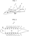
- FIG. 1 is a schematic perspective view of an aircraft 1. As illustrated in FIG. 1 , the aircraft 1 includes a fuselage 3, main wings 5, horizontal tails 7, and a vertical tail 9. The main wings 5, the horizontal tails 7, and the vertical tail 9 may also be simply referred to as "wings" below.
- the fuselage 3 extends in a roll axis direction that joins the nose side and the tail side of the aircraft 1 with each other.
- Each main wing 5 is provided on a central portion of the fuselage 3 in the roll axis direction.
- the main wings 5 are provided in a pair, one on the left side and one on the right side of the fuselage 3 in a pitch axis direction orthogonal to the roll axis direction.
- the main wings 5 extend outward from the fuselage 3 in the pitch axis direction.
- Each main wing 5 has the function of generating a vertically upward lift at the aircraft 1.
- the horizontal tails 7 are provided on the fuselage 3 rearward of (on the tail side with respect to) the main wings 5.
- the horizontal tails 7 are provided in a pair, one on the left side and the other on the right side of the fuselage 3 in the pitch axis direction.
- the horizontal tails 7 extend outward from the fuselage 3 in the pitch axis direction.
- Each horizontal tail 7 has the function of maintaining the stability of the aircraft 1 around the pitch axis.
- the vertical tail 9 is provided on the fuselage 3 rearward of (on the tail side with respect to) the main wings 5.
- the vertical tail 9 extends outward from the fuselage 3 in a yaw axis direction orthogonal to the roll axis direction and the pitch axis direction.
- the vertical tail 9 has the function of maintaining the stability of the aircraft 1 around the yaw axis.
- FIG. 2 is a schematic sectional view along line II-II of a main wing 5 illustrated in FIG. 1 .
- the main wing 5 includes a skin 11, stringers 13, and a rib 15.
- the skin 11 may serve as a "panel”
- the stringers 13 may serve as “first assembly components”
- the rib 15 may serve as a "second assembly component”.
- the skin 11 is constituted by a plate member and is formed into a streamline-shaped wing. An outer surface of the skin 11 is exposed to an external space S1, and an accommodation space S2 is formed on an inner side of the skin 11.
- Each stringer 13 has an I shape and is accommodated in the accommodation space S2.
- each stringer 13 is coupled to the skin 11 and the other end of each stringer 13 is coupled to the rib 15.
- each stringer 13 is integrated with the skin 11.
- each stringer 13 may be formed separately from the skin 11 and affixed to the skin 11.
- the rib 15 has a hollow rectangular shape and is accommodated in the accommodation space S2.
- the rib 15 spaced apart from the skin 11 is supported by the stringers 13.
- the rib 15 has a fuel containing space S3 therein.
- the rib 15 functions as a part of a fuel tank.
- the rib 15 functions as a reinforcing member that reinforces the main wing 5.
- the main wing 5 is assembled by placing the rib 15 on the stringers 13 integrated with the skin 11 and by fastening the stringers 13 and the rib 15 with a fastener (for example, a bolt).
- a fastener for example, a bolt
- the main wing 5 is assembled by an assembling device 100.
- FIG. 3 is a schematic structural view illustrating a structure of the assembling device 100 according to the present embodiment.
- the rib 15 is illustrated as having a planar shape.
- the assembling device 100 includes a holding member 101 and a processing device 103.
- the holding member 101 includes a first holding member 101a and a second holding member 101b.
- the first holding member 101a is, for example, a jig, and is disposed below the skin 11 and the stringers 13 in a vertical direction.
- the first holding member 101a holds the skin 11 and the stringers 13 in an assembly orientation at a location below the skin 11 and the stringers 13 in the vertical direction.
- a reference position (a reference mark) X1 that serves as a reference for a processing position where processing is performed by the processing device 103 exists on the first holding member 101a.
- the second holding member 101b is, for example, a jig, and is disposed above the rib 15 in the vertical direction.
- the second holding member 101b holds the rib 15 in an assembly orientation at a location above the rib 15 in the vertical direction.
- a reference position (a reference mark) X2 that serves as a reference for a processing position where processing is performed by the processing device 103 exists on the second holding member 101b.
- the skin 11 and the stringers 13 in the assembly orientation face the rib 15 in the vertical direction.
- the first holding member 101 a is formed separately from the second holding member 101b and faces the second holding member 101b in the vertical direction.
- the first holding member 101a and the second holding member 101b may be integrated with each other.
- each stringer 13 includes a first excess thickness portion 13a.
- a design shape (a design value) DVa of each stringer 13 is illustrated by a broken line. Hitherto, each stringer has been formed with this design shape DVa. In the present embodiment, the shape of each stringer 13 is larger than the design shape DVa. A portion of each stringer 13 situated outward with respect to the design shape DVa is the first excess thickness portion 13a.
- each stringer 13 of the present embodiment has a portion that is larger than the design shape DVa, and the larger portion corresponds to the first excess thickness portion 13a.
- Each first excess thickness portion 13a is provided close to (on a side facing) the rib 15 with respect to the design shape DVa of the stringer 13.
- each first excess thickness portion 13a is formed by forming each stringer 13 larger than the design shape DVa, and is integrated with the corresponding stringer 13.
- each first excess thickness portion 13a may be formed separately from the corresponding stringer 13.
- each first excess thickness portion 13a is made of a metal.
- each first excess thickness portion 13a is made of a metal that is the same as the metal out of which each stringer 13 is made.
- each first excess thickness portion 13a may be made of a metal differing from the metal out of which each stringer 13 is made, or may be made of a material differing from a metal.
- each first excess thickness portion 13a may be made of a composite material.
- the rib 15 includes second excess thickness portions 15b.
- a design shape (a design value) DVb of the rib 15 is illustrated by a broken line. Hitherto, the rib 15 has been formed with this design shape DVb. In the present embodiment, the shape of the rib 15 is larger than the design shape DVb.
- Portions of the rib 15 situated outward with respect to the design shape DVb are the second excess thickness portions 15b. That is, the rib 15 of the present embodiment has portions that are larger than the design shape DVb, and the larger portions correspond to the second excess thickness portions 15b. Each second excess thickness portion 15b is provided close to (on a side facing) the stringers 13 with respect to the design shape DVb of the stringer 13.
- each second excess thickness portion 15b is formed by forming the rib 15 larger than the design shape DVb, and is integrated with the rib 15.
- each second excess thickness portion 15b may be formed separately from the rib 15.
- mount adjustment members such as shims or spacers, on a surface of the rib 15 facing the stringers 13, and form the adjustment members as the second excess thickness portions 15b.
- each second excess thickness portion 15b is made of a metal.
- each second excess thickness portion 15b is made of a metal that is the same as the metal out of which the rib 15 is made.
- each second excess thickness portion 15b may be made of a metal differing from the metal out of which the rib 15 is made, or may be made of a material differing from a metal.
- each second excess thickness portion 15b may be made of a composite material.
- the stringers 13 of the present embodiment include the corresponding first excess thickness portions 13a
- the rib 15 of the present embodiment includes the second excess thickness portions 15b, the first excess thickness portions 13a and the second excess thickness portions 15b being provided for adjusting a gap between the stringers 13 and the rib 15.
- the first excess thickness portions 13a and the second excess thickness portions 15b face each other in the vertical direction.
- the processing device 103 is, for example, an NC processing machine, and performs NC processing on the first excess thickness portions 13a of the stringers 13 and the second excess thickness portions 15b of the rib 15.
- the processing device 103 includes a cutting tool, and cuts the first excess thickness portions 13a and the second excess thickness portions 15b.
- the processing device 103 may include a grinding tool, and may grind the first excess thickness portions 13a and the second excess thickness portions 15b.
- a gap may be formed between the plurality of assembly components. Hitherto (for example, in JP 2016-192 237 A ), the thickness of the gap between the plurality of assembly components has been measured, a shim has been manufactured by machining a workpiece three-dimensionally by a processing machine on the basis of the distribution of the measured gap thickness, and then the shim has been inserted into the gap to fill the gap with the shim.
- the first holding member 101a holds the skin 11 and the stringers 13 with the main wing 5 in an assembly orientation.
- the second holding member 101b holds the rib 15 with the main wing 5 in the assembly orientation.
- the stringers 13 include the respective first excess thickness portions 13a for adjusting a facing interval with respect to the rib 15.
- the rib 15 includes the second excess thickness portions 15b for adjusting the facing interval with respect to the stringers 13.
- the first excess thickness portions 13a and the second excess thickness portions 15b spaced apart from each other in the vertical direction face each other.
- the facing interval may correspond to a "gap".
- an assembly design shape (a design value) DSa of the skin 11 and the stringers 13 in which the reference position X1 on the first holding member 101a serves as a reference is illustrated by an alternate long and short dashed lines.
- the assembly design shape DSa is an ideal shape in terms of design when the skin 11 and the stringers 13 in the assembly orientation are held by the first holding member 101a.
- the design shape DVa of the stringers 13 above be the same as the assembly design shape DSa.
- the design shape DVa may not be the same as the assembly design shape DSa.
- FIG. 3 illustrates the case in which the design shape DVa deviates from the assembly design shape DSa due to the effect of, for example, manufacturing errors or distortions.
- the processing device 103 processes the first excess thickness portions 13a in accordance with the assembly design shape DSa.
- the processing device 103 is capable of reducing errors with respect to the assembly design shape DSa.
- the leftmost first excess thickness portion 13a is a first excess thickness portion 13a after being subjected to the NC processing by the processing device 103.
- a surface of the first excess thickness portion 13a facing the second excess thickness portion 15b is cut to the assembly design shape DSa by the processing device 103.
- the middle first excess thickness portion 13a and the rightmost first excess thickness portion 13a are first excess thickness portions 13a before being subjected to the NC processing by the processing device 103.
- each stringer 13 includes the first excess thickness portion 13a, even if the assembly design shape DSa is positioned closer than the design shape DVa to the rib 15, it is possible to perform the NC processing on the stringers 13 (the first excess thickness portions 13a).
- each first excess thickness portion 13a in the vertical direction is determined by considering deviation caused by the effects of, for example, manufacturing errors or distortions of the skin 11 and the stringers 13.
- the height of each first excess thickness portion 13a in the vertical direction is determined by adding to the design shape DVa a value that is greater than or equal to the deviation caused by the effects of, for example, manufacturing errors or distortions of the skin 11 and the stringers 13.
- an assembly design shape (a design value) DSb of the rib 15 in which the reference position X1 on the first holding member 101a serves as a reference is illustrated by an alternate long and short dashed lines.
- the assembly design shape DSb of the rib 15 in which the reference position X1 serves as a reference is described, the assembly design shape DSb of the rib 15 may be a shape in which a reference position X2 serves as a reference.
- the assembly design shape DSb is an ideal shape in terms of design when the rib 15 in the assembly orientation is held by the second holding member 101b.
- the design shape DVb of the rib 15 above be the same as the assembly design shape DSb.
- the design shape DVb of the rib 15 above may not be the same as the assembly design shape DSb.
- FIG 3 illustrates the case in which the design shape DVb deviates from the assembly design shape DSb due to the effect of, for example, manufacturing errors or distortions.
- the processing device 103 performs NC processing on the second excess thickness portions 15b in accordance with the assembly design shape DSb.
- the processing device 103 is capable of reducing errors with respect to the assembly design shape DSb.
- the leftmost second excess thickness portion 15b is a second excess thickness portion 15b after being subjected to the NC processing by the processing device 103.
- a surface of the second excess thickness portion 15b facing the first excess thickness portion 13a is cut to the assembly design shape DSb by the processing device 103.
- the middle second excess thickness portion 15b and the rightmost second excess thickness portion 15b are second excess thickness portions 15b before being subjected to the NC processing by the processing device 103.
- the rib 15 includes the second excess thickness portions 15b, even if the assembly design shape DSb is positioned closer than the design shape DVb to the stringers 13, it is possible to perform the NC processing on the rib 15 (the second excess thickness portions 15b).
- the height of each second excess thickness portion 15b in the vertical direction is determined by considering deviation caused by the effects of, for example, manufacturing errors or distortions of the rib 15.
- each second excess thickness portion 15b in the vertical direction is determined by adding to the design shape DVb a value that is greater than or equal to the deviation caused by the effects of, for example, manufacturing errors or distortions of the rib 15.
- the processing device 103 performs the NC processing on the first excess thickness portions 13a and the second excess thickness portions 15b with reference to the reference position X1 existing on the first holding member 101a.
- the processing device 103 may perform the NC processing on the first excess thickness portions 13a and the second excess thickness portions 15b with reference to the reference position X2 existing on the second holding member 101b.
- the processing device 103 may perform the NC processing on the first excess thickness portions 13a with reference to the reference position XI, and may perform the NC processing on the second excess thickness portions 15b with reference to the reference position X2.
- the processing device 103 After the processing device 103 has performed the NC processing on all of the first excess thickness portions 13a on the basis of the assembly design shape DSa and all of the second excess thickness portions 15b on the basis of the assembly design shape DSb, at least one of the first holding member 101a or the second holding member 101b moves closer to the other of the first holding member 101a and the second holding member 101b.
- the holding states of the first holding member 101a and the second holding member 101b are continued to be maintained.
- the stringers 13 and the rib 15 come into contact with each other, the first holding member 101a and the second holding member 101b stop moving.
- the first excess thickness portions 13a of the respective stringers 13 are subjected to the NC processing to have the assembly design shape DSa
- the second excess thickness portions 15b of the rib 15 are subjected to the NC processing to have the assembly design shape DSb. Therefore, even if manufacturing errors occur when the assembly components (the skin 11, the stringers 13, the rib 15) are manufactured or distortions caused by the self-weights of the assembly components in the assembly orientation occur, it is possible to reduce the gap between the plurality of assembly components that are being assembled to an NC processing precision.
- the assembling device 100 causes the stringers 13 and the rib 15 in contact with each other to be fastened to each other with a fastener (not illustrated; such as a bolt). Therefore, the skin 11, the stringers 13, and the rib 15 are integrated with each other, and thus the main wing 5 is assembled.
- the assembling device 100 of the present embodiment includes the processing device 103, and the processing device 103 processes the first excess thickness portions 13a of the stringers 13 and the second excess thickness portions 15b of the rib 15.
- the processing device 103 is capable of processing the stringers 13 (the first excess thickness portions 13a) and the rib 15 (the second excess thickness portions 15b) in the assembly orientation to the corresponding ideal shapes (the corresponding assembly design shapes DSa and DSb) in terms of design. As a result, it is possible to simplify the operation of filling the gap between the plurality of assembly components and to facilitate the assembly operation of assembling the assembly components.
- the processing device 103 processes the first excess thickness portions 13a and the second excess thickness portions 15b with reference to the reference position X1 existing on the first holding member 101a or the reference position X2 existing on the second holding member 101b.
- first excess thickness portions 13a and the second excess thickness portions 15b By processing the first excess thickness portions 13a and the second excess thickness portions 15b with reference to the reference position existing on the holding member 101, which is a jig, it is possible to process the stringers 13 (the first excess thickness portions 13a) in the assembly orientation and the rib 15 (the second excess thickness portions 15b) in the assembly orientation with high precision to have the corresponding ideal shapes (the corresponding assembly design shapes DSa and DSb) in terms of design.
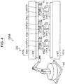
- FIG. 4 is a schematic structural view illustrating a structure of an assembling device 100A according to a modification. Structural components that substantially correspond to those of the embodiment above are given the same reference numerals and are not described below.
- FIG. 4 illustrates first excess thickness portions 113a after being processed into female portions on the basis of the assembly design shape DSa by the processing device 103 and second excess thickness portions 115b after being processed into male portions on the basis of the assembly design shape DSb by the processing device 103.
- the shapes of the processed first excess thickness portions 113a and the shapes of the processed second excess thickness portions 115b differ from the shapes of the first excess thickness portions 13a and the shapes of the second excess thickness portions 15b of the embodiment above. Since the other portions are the same as those of the assembling device 100 of the embodiment above, they are not described.
- the processing device 103 of the present modification processes the first excess thickness portions 113a and the second excess thickness portions 115b so that at least a portion of each first excess thickness portion 113a has a shape differing from the assembly design shape DSa and at least a portion of each second excess thickness portion 115b has a shape differing from the assembly design shape DSb.
- the processing device 103 processes the first excess thickness portions 113a to be smaller than the assembly design shape DSa.
- the processing device 103 processes the second excess thickness portions 115b to be larger than the assembly design shape DSb.
- Each first excess thickness portion 113a has a varying height in the width direction of the stringers 13 (in FIG. 4 , a left-right direction). For example, the height of each first excess thickness portion 113a gradually decreases with decreasing distance from the center of each stringer 13 in the width direction.
- each first excess thickness portion 113a increases gradually with increasing distance from the center of each stringer 13 in the width direction.
- each first excess thickness portion 113a has a hollow portion 113b having a central portion that is depressed with respect to the assembly design shape DSa.
- the hollow portion 113b may serve as "a first position aligner".
- Each second excess thickness portion 115b has a varying height in the width direction of the rib 15 (in FIG. 4 , a left-right direction). For example, the height of each second excess thickness portion 115b gradually increases with decreasing distance from the center of the rib 15 in the width direction. In other words, the height of each second excess thickness portion 115b decreases gradually with increasing distance from the center of the rib 15 in the width direction.
- each second excess thickness portion 115b has a protrusion 115c having a central portion that protrudes with respect to the assembly design shape DSb.
- the protrusion 115c may serve as a "second position aligner".
- the protrusions 115c are inserted into the hollow portions 113b. Facing surfaces of the hollow portions 113b and corresponding facing surfaces of the protrusions 115c that face each other are generally parallel to each other. Therefore, when the hollow portions 113b and the corresponding protrusions 115c have come into contact with each other, the facing surfaces of the hollow portions 113b and the corresponding facing surfaces of the protrusions 115c are in contact with each other.
- the positions of the stringers 13 and the position of the rib 15 in the vertical direction are determined.
- the upper surface of the assembly design shape DSa on the upper side in the vertical direction generally coincides with the lower surface of the assembly design shape DSb on the lower side in the vertical direction.
- the hollow portions 113b and the protrusions 115c When the hollow portions 113b and the protrusions 115c have come into contact with each other, the hollow portions 113b and the protrusions 115c are also in contact with each other in the width direction of the stringers 13 and the rib 15 (in FIG. 4 , the left-right direction). Therefore, the positions of the stringers 13 and the position of the rib 15 in the width direction (in FIG 4 , the left-right direction) are determined.
- the assembling device 100A of the present modification includes the processing device 103, and the processing device 103 forms the hollow portions 113b in the first excess thickness portions 113a and forms the protrusions 115c on the second excess thickness portions 115b.
- the hollow portion 113b and the protrusion 115c may serve as a "first position aligner” and a "second position aligner” respectively.
- the protrusions 115c are formed in correspondence with the hollow portions 113b.
- the hollow portions 113b and the protrusions 115c are formed for performing aligning in a direction orthogonal to the direction in which the stringers 13 and the rib 15 face each other (in FIG. 4 , the left-right direction).
- the assembling device 100A is capable of facilitating the positioning of the stringers 13 and the rib 15 in the width direction in addition to the positioning of the stringers 13 and the rib 15 in the vertical direction. As in the embodiment above, it is possible to simplify the operation of filling the gap between the plurality of assembly components and to facilitate the assembly operation of assembling the assembly components.
- the assembling devices 100 and 100A are described as being used to assemble a main wing 5 by using a skin 11, stringers 13, and a rib 15.
- the assembling devices 100 and 100A may be used to assemble the other types of wings by using a skin 11, stringers 13, and a rib 15.
- the assembling devices 100 and 100A may be used to assemble a horizontal tail 7, a vertical tail 9, or a central wing by using a skin 11, stringers 13, and a rib 15.
- the first excess thickness portions 13a and 113a and the second excess thickness portions 15b and 115b are described as being made of a metal.
- the first excess thickness portions 13a and 113a and the second excess thickness portions 15b and 115b may be made of a composite material.
- the processing device 103 performs NC processing (cutting), an oxide film is removed.
- the processing device 103 is described as processing the first excess thickness portions 13a and 113a and the second excess thickness portions 15b and 115b with reference to the reference position X1 existing on the holding member 101 or the reference position X2 existing on the holding member 101.
- the processing device 103 may process the first excess thickness portions 13a and 113a and the second excess thickness portions 15b and 115b with reference to a reference position differing from the reference positions X1 and X2.
- the processing device 103 may process the first excess thickness portions 13a and 113a and the second excess thickness portions 15b and 115b with reference to a reference position existing on the ground.
- the processing device 103 is described as forming the hollow portions 113b in the first excess thickness portions 113a and as forming the protrusions 115c on the second excess thickness portions 115b.
- the processing device 103 may form the protrusions 115c on the first excess thickness portions 113a and the hollow portions 113b in the second excess thickness portions 115b.
Landscapes
- Engineering & Computer Science (AREA)
- Mechanical Engineering (AREA)
- Manufacturing & Machinery (AREA)
- Robotics (AREA)
- Transportation (AREA)
- Aviation & Aerospace Engineering (AREA)
- Automatic Assembly (AREA)
- Numerical Control (AREA)
- Connection Of Plates (AREA)
- Moulding By Coating Moulds (AREA)
Abstract
Description
- The invention relates to an assembling device.
- For example, when assembling the fuselage and wings of an aircraft, a shim is inserted into a gap between a plurality of assembly components and the gap is filled with the shim. Japanese Unexamined Patent Application Publication
JP 2016-192 237 A - An aspect of the invention provides an assembling device including a holding member and a processing device. The holding member is configured to hold a first assembly component and a second assembly component. The processing device is configured to process a first excess thickness portion and a second excess thickness portion.
- The first excess thickness portion is provided at the first assembly component and is configured to adjust a gap between the first assembly component and the second assembly component. The second excess thickness portion is provided at the second assembly component and is configured to adjust the gap.
- The accompanying drawings are included to provide a further understanding of the invention and are incorporated in and constitute a part of this specification. The drawings illustrate embodiments and, together with the specification, serve to explain the principles of the invention.
- FIG. 1
- is a schematic perspective view of an aircraft;
- FIG. 2
- is a schematic sectional view along line II-II of a main wing illustrated in
FIG. 1 ; - FIG. 3
- is a schematic structural view illustrating a structure of an assembling device according to an embodiment; and
- FIG. 4
- is a schematic structural view illustrating a structure of an assembling device according to a modification.
- In
JP 2016-192 237 A - It is desirable to provide an assembling device that makes it possible to facilitate an assembly operation of assembling assembly components.
- In the following, an embodiment of the invention is described in detail with reference to the accompanying drawings. Note that the following description is directed to an illustrative example of the invention and not to be construed as limiting to the invention. Factors including, without limitation, numerical values, shapes, materials, components, positions of the components, and how the components are coupled to each other are illustrative only and not to be construed as limiting to the invention.
- Further, elements in the following embodiment which are not recited in a most-generic independent claim of the invention are optional and may be provided on an as-needed basis. The drawings are schematic and are not intended to be drawn to scale. Throughout the present specification and the drawings, elements having substantially the same function and configuration are denoted with the same numerals to avoid any redundant description.
-
FIG. 1 is a schematic perspective view of anaircraft 1. As illustrated inFIG. 1 , theaircraft 1 includes afuselage 3,main wings 5,horizontal tails 7, and avertical tail 9. Themain wings 5, thehorizontal tails 7, and thevertical tail 9 may also be simply referred to as "wings" below. - The
fuselage 3 extends in a roll axis direction that joins the nose side and the tail side of theaircraft 1 with each other. Eachmain wing 5 is provided on a central portion of thefuselage 3 in the roll axis direction. - The
main wings 5 are provided in a pair, one on the left side and one on the right side of thefuselage 3 in a pitch axis direction orthogonal to the roll axis direction. Themain wings 5 extend outward from thefuselage 3 in the pitch axis direction. Eachmain wing 5 has the function of generating a vertically upward lift at theaircraft 1. - The
horizontal tails 7 are provided on thefuselage 3 rearward of (on the tail side with respect to) themain wings 5. Thehorizontal tails 7 are provided in a pair, one on the left side and the other on the right side of thefuselage 3 in the pitch axis direction. Thehorizontal tails 7 extend outward from thefuselage 3 in the pitch axis direction. Eachhorizontal tail 7 has the function of maintaining the stability of theaircraft 1 around the pitch axis. - The
vertical tail 9 is provided on thefuselage 3 rearward of (on the tail side with respect to) themain wings 5. Thevertical tail 9 extends outward from thefuselage 3 in a yaw axis direction orthogonal to the roll axis direction and the pitch axis direction. Thevertical tail 9 has the function of maintaining the stability of theaircraft 1 around the yaw axis. -
FIG. 2 is a schematic sectional view along line II-II of amain wing 5 illustrated inFIG. 1 . As illustrated inFIG. 2 , themain wing 5 includes askin 11,stringers 13, and arib 15. In one embodiment, theskin 11 may serve as a "panel", thestringers 13 may serve as "first assembly components", and therib 15 may serve as a "second assembly component". - The
skin 11 is constituted by a plate member and is formed into a streamline-shaped wing. An outer surface of theskin 11 is exposed to an external space S1, and an accommodation space S2 is formed on an inner side of theskin 11. Eachstringer 13 has an I shape and is accommodated in the accommodation space S2. - One end of each
stringer 13 is coupled to theskin 11 and the other end of eachstringer 13 is coupled to therib 15. In the present embodiment, eachstringer 13 is integrated with theskin 11. However, eachstringer 13 may be formed separately from theskin 11 and affixed to theskin 11. - The
rib 15 has a hollow rectangular shape and is accommodated in the accommodation space S2. Therib 15 spaced apart from theskin 11 is supported by thestringers 13. Therib 15 has a fuel containing space S3 therein. In the present embodiment, therib 15 functions as a part of a fuel tank. In addition, therib 15 functions as a reinforcing member that reinforces themain wing 5. - The
main wing 5 is assembled by placing therib 15 on thestringers 13 integrated with theskin 11 and by fastening thestringers 13 and therib 15 with a fastener (for example, a bolt). In the present embodiment, themain wing 5 is assembled by an assemblingdevice 100. -
FIG. 3 is a schematic structural view illustrating a structure of the assemblingdevice 100 according to the present embodiment. In order to make it easier to viewFIG. 3 , therib 15 is illustrated as having a planar shape. As illustrated inFIG. 3 , the assemblingdevice 100 includes a holdingmember 101 and aprocessing device 103. The holdingmember 101 includes afirst holding member 101a and asecond holding member 101b. - The
first holding member 101a is, for example, a jig, and is disposed below theskin 11 and thestringers 13 in a vertical direction. Thefirst holding member 101a holds theskin 11 and thestringers 13 in an assembly orientation at a location below theskin 11 and thestringers 13 in the vertical direction. A reference position (a reference mark) X1 that serves as a reference for a processing position where processing is performed by theprocessing device 103 exists on the first holdingmember 101a. - The
second holding member 101b is, for example, a jig, and is disposed above therib 15 in the vertical direction. Thesecond holding member 101b holds therib 15 in an assembly orientation at a location above therib 15 in the vertical direction. A reference position (a reference mark) X2 that serves as a reference for a processing position where processing is performed by theprocessing device 103 exists on the second holdingmember 101b. - The
skin 11 and thestringers 13 in the assembly orientation face therib 15 in the vertical direction. In the present embodiment, the first holdingmember 101 a is formed separately from the second holdingmember 101b and faces the second holdingmember 101b in the vertical direction. However, the first holdingmember 101a and the second holdingmember 101b may be integrated with each other. - As illustrated in
FIG. 3 , eachstringer 13 includes a firstexcess thickness portion 13a. InFIG. 3 , a design shape (a design value) DVa of eachstringer 13 is illustrated by a broken line. Hitherto, each stringer has been formed with this design shape DVa. In the present embodiment, the shape of eachstringer 13 is larger than the design shape DVa. A portion of eachstringer 13 situated outward with respect to the design shape DVa is the firstexcess thickness portion 13a. - That is, each
stringer 13 of the present embodiment has a portion that is larger than the design shape DVa, and the larger portion corresponds to the firstexcess thickness portion 13a. Each firstexcess thickness portion 13a is provided close to (on a side facing) therib 15 with respect to the design shape DVa of thestringer 13. - In the present embodiment, each first
excess thickness portion 13a is formed by forming eachstringer 13 larger than the design shape DVa, and is integrated with the correspondingstringer 13. However, each firstexcess thickness portion 13a may be formed separately from the correspondingstringer 13. For example, it is possible to form eachstringer 13 with the design shape DVa, mount an adjustment member, such as a shim or a spacer, on a surface of eachstringer 13 facing therib 15, and form the adjustment member as the firstexcess thickness portion 13a. - In the present embodiment, each first
excess thickness portion 13a is made of a metal. For example, each firstexcess thickness portion 13a is made of a metal that is the same as the metal out of which eachstringer 13 is made. However, each firstexcess thickness portion 13a may be made of a metal differing from the metal out of which eachstringer 13 is made, or may be made of a material differing from a metal. For example, each firstexcess thickness portion 13a may be made of a composite material. - The
rib 15 includes secondexcess thickness portions 15b. InFIG. 3 , a design shape (a design value) DVb of therib 15 is illustrated by a broken line. Hitherto, therib 15 has been formed with this design shape DVb. In the present embodiment, the shape of therib 15 is larger than the design shape DVb. - Portions of the
rib 15 situated outward with respect to the design shape DVb are the secondexcess thickness portions 15b. That is, therib 15 of the present embodiment has portions that are larger than the design shape DVb, and the larger portions correspond to the secondexcess thickness portions 15b. Each secondexcess thickness portion 15b is provided close to (on a side facing) thestringers 13 with respect to the design shape DVb of thestringer 13. - In the present embodiment, each second
excess thickness portion 15b is formed by forming therib 15 larger than the design shape DVb, and is integrated with therib 15. However, each secondexcess thickness portion 15b may be formed separately from therib 15. For example, it is possible to form therib 15 with the design shape DVb, mount adjustment members, such as shims or spacers, on a surface of therib 15 facing thestringers 13, and form the adjustment members as the secondexcess thickness portions 15b. - In the present embodiment, each second
excess thickness portion 15b is made of a metal. For example, each secondexcess thickness portion 15b is made of a metal that is the same as the metal out of which therib 15 is made. - However, each second
excess thickness portion 15b may be made of a metal differing from the metal out of which therib 15 is made, or may be made of a material differing from a metal. For example, each secondexcess thickness portion 15b may be made of a composite material. - In this way, the
stringers 13 of the present embodiment include the corresponding firstexcess thickness portions 13a, and therib 15 of the present embodiment includes the secondexcess thickness portions 15b, the firstexcess thickness portions 13a and the secondexcess thickness portions 15b being provided for adjusting a gap between thestringers 13 and therib 15. The firstexcess thickness portions 13a and the secondexcess thickness portions 15b face each other in the vertical direction. - The
processing device 103 is, for example, an NC processing machine, and performs NC processing on the firstexcess thickness portions 13a of thestringers 13 and the secondexcess thickness portions 15b of therib 15. In the present embodiment, theprocessing device 103 includes a cutting tool, and cuts the firstexcess thickness portions 13a and the secondexcess thickness portions 15b. However, theprocessing device 103 may include a grinding tool, and may grind the firstexcess thickness portions 13a and the secondexcess thickness portions 15b. - When the
fuselage 3 and the wings (themain wings 5, thehorizontal tails 7, and the vertical tail 9) of theaircraft 1 are to be assembled, a gap may be formed between the plurality of assembly components. Hitherto (for example, inJP 2016-192 237 A - In this way, hitherto, in order to fill the gap between the plurality of assembly components, many operational steps, such as the step of measuring the gap between the plurality of assembly components, the step of manufacturing a shim, and the step of inserting the shim, have been performed. Therefore, the assembly operation of assembling the assembly components may be complicated.
- The assembly operation of assembling a
main wing 5 by the assemblingdevice 100 of the present embodiment is described below. As illustrated inFIG. 3 , first, the first holdingmember 101a holds theskin 11 and thestringers 13 with themain wing 5 in an assembly orientation. Thesecond holding member 101b holds therib 15 with themain wing 5 in the assembly orientation. - Here, as described above, the
stringers 13 include the respective firstexcess thickness portions 13a for adjusting a facing interval with respect to therib 15. Therib 15 includes the secondexcess thickness portions 15b for adjusting the facing interval with respect to thestringers 13. In the assembly orientation, the firstexcess thickness portions 13a and the secondexcess thickness portions 15b spaced apart from each other in the vertical direction face each other. In one embodiment, the facing interval may correspond to a "gap". - Next, the
processing device 103 performs NC processing on the firstexcess thickness portions 13a and the secondexcess thickness portions 15b. InFIG. 3 , an assembly design shape (a design value) DSa of theskin 11 and thestringers 13 in which the reference position X1 on the first holdingmember 101a serves as a reference is illustrated by an alternate long and short dashed lines. The assembly design shape DSa is an ideal shape in terms of design when theskin 11 and thestringers 13 in the assembly orientation are held by the first holdingmember 101a. - It is desirable that the design shape DVa of the
stringers 13 above be the same as the assembly design shape DSa. However, due to, for example, manufacturing errors occurring when theskin 11 and thestringers 13 have been manufactured or distortions caused by the self-weights of theskin 11 and thestringers 13 in the assembly orientation, the design shape DVa may not be the same as the assembly design shape DSa.FIG. 3 illustrates the case in which the design shape DVa deviates from the assembly design shape DSa due to the effect of, for example, manufacturing errors or distortions. - With reference to the reference position X1 existing on the first holding
member 101a, theprocessing device 103 processes the firstexcess thickness portions 13a in accordance with the assembly design shape DSa. By performing NC processing on the firstexcess thickness portions 13a with theskin 11 and thestringers 13 in the assembly orientation, theprocessing device 103 is capable of reducing errors with respect to the assembly design shape DSa. - In
FIG. 3 , among the three firstexcess thickness portions 13a, the leftmost firstexcess thickness portion 13a is a firstexcess thickness portion 13a after being subjected to the NC processing by theprocessing device 103. A surface of the firstexcess thickness portion 13a facing the secondexcess thickness portion 15b is cut to the assembly design shape DSa by theprocessing device 103. - In
FIG. 3 , among the three firstexcess thickness portions 13a, the middle firstexcess thickness portion 13a and the rightmost firstexcess thickness portion 13a are firstexcess thickness portions 13a before being subjected to the NC processing by theprocessing device 103. - Since each
stringer 13 includes the firstexcess thickness portion 13a, even if the assembly design shape DSa is positioned closer than the design shape DVa to therib 15, it is possible to perform the NC processing on the stringers 13 (the firstexcess thickness portions 13a). - Here, the height of each first
excess thickness portion 13a in the vertical direction is determined by considering deviation caused by the effects of, for example, manufacturing errors or distortions of theskin 11 and thestringers 13. For example, the height of each firstexcess thickness portion 13a in the vertical direction is determined by adding to the design shape DVa a value that is greater than or equal to the deviation caused by the effects of, for example, manufacturing errors or distortions of theskin 11 and thestringers 13. - In
FIG. 3 , an assembly design shape (a design value) DSb of therib 15 in which the reference position X1 on the first holdingmember 101a serves as a reference is illustrated by an alternate long and short dashed lines. Here, although the assembly design shape DSb of therib 15 in which the reference position X1 serves as a reference is described, the assembly design shape DSb of therib 15 may be a shape in which a reference position X2 serves as a reference. The assembly design shape DSb is an ideal shape in terms of design when therib 15 in the assembly orientation is held by the second holdingmember 101b. - It is desirable that the design shape DVb of the
rib 15 above be the same as the assembly design shape DSb. However, due to, for example, manufacturing errors occurring when therib 15 has been manufactured or distortions caused by the self-weight of therib 15 in the assembly orientation, the design shape DVb of therib 15 above may not be the same as the assembly design shape DSb.FIG 3 illustrates the case in which the design shape DVb deviates from the assembly design shape DSb due to the effect of, for example, manufacturing errors or distortions. - With reference to the reference position X1 existing on the first holding
member 101a, theprocessing device 103 performs NC processing on the secondexcess thickness portions 15b in accordance with the assembly design shape DSb. By performing the NC processing on the secondexcess thickness portions 15b with therib 15 in the assembly orientation, theprocessing device 103 is capable of reducing errors with respect to the assembly design shape DSb. InFIG. 3 , among the three secondexcess thickness portions 15b, the leftmost secondexcess thickness portion 15b is a secondexcess thickness portion 15b after being subjected to the NC processing by theprocessing device 103. - A surface of the second
excess thickness portion 15b facing the firstexcess thickness portion 13a is cut to the assembly design shape DSb by theprocessing device 103. InFIG. 3 , among the three secondexcess thickness portions 15b, the middle secondexcess thickness portion 15b and the rightmost secondexcess thickness portion 15b are secondexcess thickness portions 15b before being subjected to the NC processing by theprocessing device 103. - Since the
rib 15 includes the secondexcess thickness portions 15b, even if the assembly design shape DSb is positioned closer than the design shape DVb to thestringers 13, it is possible to perform the NC processing on the rib 15 (the secondexcess thickness portions 15b). Here, the height of each secondexcess thickness portion 15b in the vertical direction is determined by considering deviation caused by the effects of, for example, manufacturing errors or distortions of therib 15. - For example, the height of each second
excess thickness portion 15b in the vertical direction is determined by adding to the design shape DVb a value that is greater than or equal to the deviation caused by the effects of, for example, manufacturing errors or distortions of therib 15. - In this way, in the present embodiment, the
processing device 103 performs the NC processing on the firstexcess thickness portions 13a and the secondexcess thickness portions 15b with reference to the reference position X1 existing on the first holdingmember 101a. However, theprocessing device 103 may perform the NC processing on the firstexcess thickness portions 13a and the secondexcess thickness portions 15b with reference to the reference position X2 existing on the second holdingmember 101b. - Alternatively, the
processing device 103 may perform the NC processing on the firstexcess thickness portions 13a with reference to the reference position XI, and may perform the NC processing on the secondexcess thickness portions 15b with reference to the reference position X2. - After the
processing device 103 has performed the NC processing on all of the firstexcess thickness portions 13a on the basis of the assembly design shape DSa and all of the secondexcess thickness portions 15b on the basis of the assembly design shape DSb, at least one of the first holdingmember 101a or the second holdingmember 101b moves closer to the other of the first holdingmember 101a and the second holdingmember 101b. - Here, the holding states of the first holding
member 101a and the second holdingmember 101b (that is, the assembly orientations of theskin 11, thestringers 13, and the rib 15) are continued to be maintained. When thestringers 13 and therib 15 come into contact with each other, the first holdingmember 101a and the second holdingmember 101b stop moving. - Here, the first
excess thickness portions 13a of therespective stringers 13 are subjected to the NC processing to have the assembly design shape DSa, and the secondexcess thickness portions 15b of therib 15 are subjected to the NC processing to have the assembly design shape DSb. Therefore, even if manufacturing errors occur when the assembly components (theskin 11, thestringers 13, the rib 15) are manufactured or distortions caused by the self-weights of the assembly components in the assembly orientation occur, it is possible to reduce the gap between the plurality of assembly components that are being assembled to an NC processing precision. - Therefore, it is possible not to perform, for example, the step of measuring the gap between the plurality of assembly components, the step of manufacturing a shim, and the step of inserting the shim, and to simplify the operation of filling the gap between the plurality of assembly components.
- The assembling
device 100 causes thestringers 13 and therib 15 in contact with each other to be fastened to each other with a fastener (not illustrated; such as a bolt). Therefore, theskin 11, thestringers 13, and therib 15 are integrated with each other, and thus themain wing 5 is assembled. - As described above, the assembling
device 100 of the present embodiment includes theprocessing device 103, and theprocessing device 103 processes the firstexcess thickness portions 13a of thestringers 13 and the secondexcess thickness portions 15b of therib 15. - Therefore, the
processing device 103 is capable of processing the stringers 13 (the firstexcess thickness portions 13a) and the rib 15 (the secondexcess thickness portions 15b) in the assembly orientation to the corresponding ideal shapes (the corresponding assembly design shapes DSa and DSb) in terms of design. As a result, it is possible to simplify the operation of filling the gap between the plurality of assembly components and to facilitate the assembly operation of assembling the assembly components. - The
processing device 103 processes the firstexcess thickness portions 13a and the secondexcess thickness portions 15b with reference to the reference position X1 existing on the first holdingmember 101a or the reference position X2 existing on the second holdingmember 101b. - By processing the first
excess thickness portions 13a and the secondexcess thickness portions 15b with reference to the reference position existing on the holdingmember 101, which is a jig, it is possible to process the stringers 13 (the firstexcess thickness portions 13a) in the assembly orientation and the rib 15 (the secondexcess thickness portions 15b) in the assembly orientation with high precision to have the corresponding ideal shapes (the corresponding assembly design shapes DSa and DSb) in terms of design. -
FIG. 4 is a schematic structural view illustrating a structure of anassembling device 100A according to a modification. Structural components that substantially correspond to those of the embodiment above are given the same reference numerals and are not described below. -
FIG. 4 illustrates firstexcess thickness portions 113a after being processed into female portions on the basis of the assembly design shape DSa by theprocessing device 103 and second excess thickness portions 115b after being processed into male portions on the basis of the assembly design shape DSb by theprocessing device 103. - As illustrated in
FIG. 4 , in theassembling device 100A of the present modification, the shapes of the processed firstexcess thickness portions 113a and the shapes of the processed second excess thickness portions 115b differ from the shapes of the firstexcess thickness portions 13a and the shapes of the secondexcess thickness portions 15b of the embodiment above. Since the other portions are the same as those of the assemblingdevice 100 of the embodiment above, they are not described. - The
processing device 103 of the present modification processes the firstexcess thickness portions 113a and the second excess thickness portions 115b so that at least a portion of each firstexcess thickness portion 113a has a shape differing from the assembly design shape DSa and at least a portion of each second excess thickness portion 115b has a shape differing from the assembly design shape DSb. For example, theprocessing device 103 processes the firstexcess thickness portions 113a to be smaller than the assembly design shape DSa. In addition, theprocessing device 103 processes the second excess thickness portions 115b to be larger than the assembly design shape DSb. - Each first
excess thickness portion 113a has a varying height in the width direction of the stringers 13 (inFIG. 4 , a left-right direction). For example, the height of each firstexcess thickness portion 113a gradually decreases with decreasing distance from the center of eachstringer 13 in the width direction. - In other words, the height of each first
excess thickness portion 113a increases gradually with increasing distance from the center of eachstringer 13 in the width direction. As illustrated inFIG. 4 , each firstexcess thickness portion 113a has ahollow portion 113b having a central portion that is depressed with respect to the assembly design shape DSa. In one embodiment, thehollow portion 113b may serve as "a first position aligner". - Each second excess thickness portion 115b has a varying height in the width direction of the rib 15 (in
FIG. 4 , a left-right direction). For example, the height of each second excess thickness portion 115b gradually increases with decreasing distance from the center of therib 15 in the width direction. In other words, the height of each second excess thickness portion 115b decreases gradually with increasing distance from the center of therib 15 in the width direction. - As illustrated in
FIG. 4 , each second excess thickness portion 115b has a protrusion 115c having a central portion that protrudes with respect to the assembly design shape DSb. In one embodiment, the protrusion 115c may serve as a "second position aligner". - When the first
excess thickness portions 113a and the second excess thickness portions 115b come close to each other, the protrusions 115c are inserted into thehollow portions 113b. Facing surfaces of thehollow portions 113b and corresponding facing surfaces of the protrusions 115c that face each other are generally parallel to each other. Therefore, when thehollow portions 113b and the corresponding protrusions 115c have come into contact with each other, the facing surfaces of thehollow portions 113b and the corresponding facing surfaces of the protrusions 115c are in contact with each other. - When the
hollow portions 113b and the protrusions 115c have come into contact with each other, the positions of thestringers 13 and the position of therib 15 in the vertical direction are determined. Here, the upper surface of the assembly design shape DSa on the upper side in the vertical direction generally coincides with the lower surface of the assembly design shape DSb on the lower side in the vertical direction. - When the
hollow portions 113b and the protrusions 115c have come into contact with each other, thehollow portions 113b and the protrusions 115c are also in contact with each other in the width direction of thestringers 13 and the rib 15 (inFIG. 4 , the left-right direction). Therefore, the positions of thestringers 13 and the position of therib 15 in the width direction (inFIG 4 , the left-right direction) are determined. - As described above, the assembling
device 100A of the present modification includes theprocessing device 103, and theprocessing device 103 forms thehollow portions 113b in the firstexcess thickness portions 113a and forms the protrusions 115c on the second excess thickness portions 115b. In one embodiment, thehollow portion 113b and the protrusion 115c may serve as a "first position aligner" and a "second position aligner" respectively. The protrusions 115c are formed in correspondence with thehollow portions 113b. Thehollow portions 113b and the protrusions 115c are formed for performing aligning in a direction orthogonal to the direction in which thestringers 13 and therib 15 face each other (inFIG. 4 , the left-right direction). - Therefore, the assembling
device 100A is capable of facilitating the positioning of thestringers 13 and therib 15 in the width direction in addition to the positioning of thestringers 13 and therib 15 in the vertical direction. As in the embodiment above, it is possible to simplify the operation of filling the gap between the plurality of assembly components and to facilitate the assembly operation of assembling the assembly components. - Although an embodiment and a modification of the invention have been described above with reference to the attached drawings, needless to say, the invention is not limited to such an embodiment and a modification. It is obvious that any person skilled in the art can arrive at various exemplary changes and modifications within the category described in the scope of the claims, and such changes and modifications are understood to naturally belong to the technical scope of the embodiment of the invention.
- In the embodiment and the modification above, the assembling
devices main wing 5 by using askin 11,stringers 13, and arib 15. However, the assemblingdevices skin 11,stringers 13, and arib 15. For example, the assemblingdevices horizontal tail 7, avertical tail 9, or a central wing by using askin 11,stringers 13, and arib 15. - In the embodiment and the modification above, the first
excess thickness portions excess thickness portions 15b and 115b are described as being made of a metal. However, the firstexcess thickness portions excess thickness portions 15b and 115b may be made of a composite material. Here, when the firstexcess thickness portions excess thickness portions 15b and 115b are made of a metal, if theprocessing device 103 performs NC processing (cutting), an oxide film is removed. - Therefore, post-processing for applying the oxide film is performed. In contrast, making the first
excess thickness portions excess thickness portions 15b and 115b out of a composite material is advantageous in that such post-processing for applying an oxide film after theprocessing device 103 has performed NC processing is not performed. - In the embodiment and the modification above, the
processing device 103 is described as processing the firstexcess thickness portions excess thickness portions 15b and 115b with reference to the reference position X1 existing on the holdingmember 101 or the reference position X2 existing on the holdingmember 101. - However, the
processing device 103 may process the firstexcess thickness portions excess thickness portions 15b and 115b with reference to a reference position differing from the reference positions X1 and X2. For example, theprocessing device 103 may process the firstexcess thickness portions excess thickness portions 15b and 115b with reference to a reference position existing on the ground. - In the modification above, the
processing device 103 is described as forming thehollow portions 113b in the firstexcess thickness portions 113a and as forming the protrusions 115c on the second excess thickness portions 115b. However, theprocessing device 103 may form the protrusions 115c on the firstexcess thickness portions 113a and thehollow portions 113b in the second excess thickness portions 115b. -
- 1
- aircraft
- 3
- fuselage
- 5
- main wings
- 7
- horizontal tails
- 9
- vertical tail
- 11
- skin
- 13
- stringers
- 13a
- first excess thickness portion
- 15
- rib
- 15b
- second excess thickness portion
- 100
- assembling device
- 100A
- assembling device
- 101
- holding member
- 101a
- first holding member
- 101b
- second holding member
- 103
- processing device
- 113a
- first excess thickness portion
- 113b
- hollow portions
- 115b
- second excess thickness portion
- 115c
- protrusions
- S1
- external space
- S2
- accommodation space
- X1
- reference position
- X2
- reference position
- DVa
- design shape of 13
- DVb
- design shape of 15
- DSa
- design shape of 11
- DSb
- design shape of 15
Claims (4)
- An assembling device (100) comprising:- a holding member (101) configured to hold a first assembly component (13) and a second assembly component (15); and- a processing device (103) configured to process a first excess thickness portion (13a) and a second excess thickness portion (15b), the first excess thickness portion (13a) being provided at the first assembly component (13) and being configured to adjust a gap between the first assembly component (13) and the second assembly component (15), the second excess thickness portion (15b) being provided at the second assembly component (15) and being configured to adjust the gap.
- The assembling device (100) according to claim 1,
wherein the processing device (103) is configured to process the first excess thickness portion (13a) and the second excess thickness portion (15b) with reference to a reference position (XI, X2) existing on the holding member (101). - The assembling device (100) according to claim 1 or claim 2,
wherein the processing device (103) is configured to process the first excess thickness portion (13a) and the second excess thickness portion (15b) on a basis of a design shape (DVa) of the first assembly component (13) and a design shape (DVb) of the second assembly component (15). - The assembling device (100) according to any one of claims 1 to 3,
wherein the processing device (103) is configured to form a first position aligner (113b) at the first excess thickness portion (113a) and to form a second position aligner (115c) at the second excess thickness portion (115b), the first position aligner (113b) being configured to perform aligning of the first excess thickness portion (113a) and the second excess thickness portion (115b) in a direction orthogonal to a direction in which the first assembly component (13) and the second assembly component (15) face each other, the second position aligner (115c) being provided in correspondence with the first position aligner (113b).
Applications Claiming Priority (1)
| Application Number | Priority Date | Filing Date | Title |
|---|---|---|---|
| JP2019180416A JP7324109B2 (en) | 2019-09-30 | 2019-09-30 | Assembly equipment |
Publications (3)
| Publication Number | Publication Date |
|---|---|
| EP3798135A1 true EP3798135A1 (en) | 2021-03-31 |
| EP3798135C0 EP3798135C0 (en) | 2024-10-02 |
| EP3798135B1 EP3798135B1 (en) | 2024-10-02 |
Family
ID=72521367
Family Applications (1)
| Application Number | Title | Priority Date | Filing Date |
|---|---|---|---|
| EP20192968.4A Active EP3798135B1 (en) | 2019-09-30 | 2020-08-26 | Assembling device |
Country Status (3)
| Country | Link |
|---|---|
| US (1) | US11679457B2 (en) |
| EP (1) | EP3798135B1 (en) |
| JP (1) | JP7324109B2 (en) |
Families Citing this family (2)
| Publication number | Priority date | Publication date | Assignee | Title |
|---|---|---|---|---|
| JP7820126B2 (en) * | 2020-11-18 | 2026-02-25 | ザ・ボーイング・カンパニー | Assembly line manufacturing and aircraft wing assembly |
| CN115285372B (en) * | 2022-08-11 | 2024-11-12 | 天津飞悦航空科技股份有限公司 | Tooling equipment and assembly method for vertical tail leading edge structure |
Citations (5)
| Publication number | Priority date | Publication date | Assignee | Title |
|---|---|---|---|---|
| US20020078545A1 (en) * | 1996-03-22 | 2002-06-27 | Munk Clayton L. | Determinant wing assembly |
| WO2014168681A1 (en) * | 2013-04-11 | 2014-10-16 | Raytheon Company | Inverse-Contour Machining to Eliminate Residual Stress Distortion |
| JP2016192237A (en) | 2016-08-04 | 2016-11-10 | 加賀産業株式会社 | Sim production method |
| EP3315418A1 (en) * | 2016-10-26 | 2018-05-02 | Embraer S.A. | Automated system and method to manufacture aeronautic junction parts |
| US20190031315A1 (en) * | 2017-07-31 | 2019-01-31 | Airbus Operations Limited | Assembly apparatus for forming an interfay joint during manufacture of an aircraft |
Family Cites Families (4)
| Publication number | Priority date | Publication date | Assignee | Title |
|---|---|---|---|---|
| US3979817A (en) * | 1974-11-04 | 1976-09-14 | Norfield Manufacturing Co. | Door hinge applying method |
| JPH01295726A (en) * | 1988-05-19 | 1989-11-29 | Aida Eng Ltd | Assembly method for equipment having clearance between members |
| JP2001300823A (en) | 2000-04-19 | 2001-10-30 | Japan Aircraft Mfg Co Ltd | Assembly jig device |
| US7043331B2 (en) * | 2004-04-22 | 2006-05-09 | Hallgrimur Sigtryggsson | Method of manufacturing a plurality of wooden products |
-
2019
- 2019-09-30 JP JP2019180416A patent/JP7324109B2/en active Active
-
2020
- 2020-08-26 EP EP20192968.4A patent/EP3798135B1/en active Active
- 2020-08-27 US US16/947,999 patent/US11679457B2/en active Active
Patent Citations (6)
| Publication number | Priority date | Publication date | Assignee | Title |
|---|---|---|---|---|
| US20020078545A1 (en) * | 1996-03-22 | 2002-06-27 | Munk Clayton L. | Determinant wing assembly |
| WO2014168681A1 (en) * | 2013-04-11 | 2014-10-16 | Raytheon Company | Inverse-Contour Machining to Eliminate Residual Stress Distortion |
| JP2016192237A (en) | 2016-08-04 | 2016-11-10 | 加賀産業株式会社 | Sim production method |
| EP3315418A1 (en) * | 2016-10-26 | 2018-05-02 | Embraer S.A. | Automated system and method to manufacture aeronautic junction parts |
| US10324426B2 (en) * | 2016-10-26 | 2019-06-18 | Embraer S.A. | Automated system and method to manufacture aeronautic junction parts |
| US20190031315A1 (en) * | 2017-07-31 | 2019-01-31 | Airbus Operations Limited | Assembly apparatus for forming an interfay joint during manufacture of an aircraft |
Also Published As
| Publication number | Publication date |
|---|---|
| JP7324109B2 (en) | 2023-08-09 |
| US11679457B2 (en) | 2023-06-20 |
| US20210094133A1 (en) | 2021-04-01 |
| EP3798135C0 (en) | 2024-10-02 |
| EP3798135B1 (en) | 2024-10-02 |
| JP2021053764A (en) | 2021-04-08 |
Similar Documents
| Publication | Publication Date | Title |
|---|---|---|
| EP3798135B1 (en) | Assembling device | |
| CN104476118A (en) | Manufacturing method of airplane chemical milling skin three-dimensional chemical milling sample plate | |
| CN101987338A (en) | Punch tool comprising a stamp supported in a floating manner | |
| EP2583814B1 (en) | Method for manufacturing t-shaped aircraft beams and a curing tool used during same | |
| JP6927849B2 (en) | Automatic systems and methods for manufacturing aircraft junction parts | |
| EP3827924A1 (en) | Assembly apparatus | |
| EP3331761B1 (en) | Aircraft part assembly | |
| CN109719308B (en) | Annular mortise machining tool setting method | |
| CN103143747B (en) | Processing method for double-layered separating wall kind-part hole and assembly clamp of double-layered separating wall kind-part | |
| CN221476216U (en) | Forming assembly frame | |
| CN114633133B (en) | Airplane special-shaped part clamping auxiliary device and clamping method thereof | |
| US8696340B2 (en) | Re-usable retainers for co-bonding uncured stringers | |
| CN112906141A (en) | Method for compensating axial size of circular knife | |
| EP2492191B1 (en) | Panel member, aircraft main wing, and method for forming panel member | |
| US11904420B2 (en) | Method for manufacturing a turbomachine compressor blade by compacting | |
| WO2022059047A1 (en) | Composite component and method for producing composite component | |
| CN115741152A (en) | Machining method for ensuring geometric tolerance of key assembly hole of long-shaft part | |
| CN121105436B (en) | Precise hole making process method for large-size carbon fiber composite material wallboard | |
| CN110434625A (en) | A kind of method and device for blade surplus centering long-pending folded axle when uneven | |
| US20240017498A1 (en) | Method for manufacturing an article on top of a base device | |
| CN209918915U (en) | Tool holder assembly with high tool holder positioning accuracy | |
| KR101923070B1 (en) | Manufacturing Method of Storbe Light housing | |
| CN113953778A (en) | Precision machining method for large-scale framework welding structure combined square box | |
| CN110715719A (en) | Flexible hinge module, flexible hinge module processing auxiliary device and method | |
| EP3127821A1 (en) | Aircraft part assembly |
Legal Events
| Date | Code | Title | Description |
|---|---|---|---|
| PUAI | Public reference made under article 153(3) epc to a published international application that has entered the european phase |
Free format text: ORIGINAL CODE: 0009012 |
|
| STAA | Information on the status of an ep patent application or granted ep patent |
Free format text: STATUS: THE APPLICATION HAS BEEN PUBLISHED |
|
| AK | Designated contracting states |
Kind code of ref document: A1 Designated state(s): AL AT BE BG CH CY CZ DE DK EE ES FI FR GB GR HR HU IE IS IT LI LT LU LV MC MK MT NL NO PL PT RO RS SE SI SK SM TR |
|
| AX | Request for extension of the european patent |
Extension state: BA ME |
|
| STAA | Information on the status of an ep patent application or granted ep patent |
Free format text: STATUS: REQUEST FOR EXAMINATION WAS MADE |
|
| 17P | Request for examination filed |
Effective date: 20210927 |
|
| RBV | Designated contracting states (corrected) |
Designated state(s): AL AT BE BG CH CY CZ DE DK EE ES FI FR GB GR HR HU IE IS IT LI LT LU LV MC MK MT NL NO PL PT RO RS SE SI SK SM TR |
|
| STAA | Information on the status of an ep patent application or granted ep patent |
Free format text: STATUS: EXAMINATION IS IN PROGRESS |
|
| 17Q | First examination report despatched |
Effective date: 20221118 |
|
| GRAP | Despatch of communication of intention to grant a patent |
Free format text: ORIGINAL CODE: EPIDOSNIGR1 |
|
| STAA | Information on the status of an ep patent application or granted ep patent |
Free format text: STATUS: GRANT OF PATENT IS INTENDED |
|
| INTG | Intention to grant announced |
Effective date: 20240321 |
|
| GRAS | Grant fee paid |
Free format text: ORIGINAL CODE: EPIDOSNIGR3 |
|
| GRAA | (expected) grant |
Free format text: ORIGINAL CODE: 0009210 |
|
| STAA | Information on the status of an ep patent application or granted ep patent |
Free format text: STATUS: THE PATENT HAS BEEN GRANTED |
|
| AK | Designated contracting states |
Kind code of ref document: B1 Designated state(s): AL AT BE BG CH CY CZ DE DK EE ES FI FR GB GR HR HU IE IS IT LI LT LU LV MC MK MT NL NO PL PT RO RS SE SI SK SM TR |
|
| REG | Reference to a national code |
Ref country code: GB Ref legal event code: FG4D |
|
| REG | Reference to a national code |
Ref country code: CH Ref legal event code: EP |
|
| REG | Reference to a national code |
Ref country code: DE Ref legal event code: R096 Ref document number: 602020038617 Country of ref document: DE |
|
| REG | Reference to a national code |
Ref country code: IE Ref legal event code: FG4D |
|
| U01 | Request for unitary effect filed |
Effective date: 20241023 |
|
| U07 | Unitary effect registered |
Designated state(s): AT BE BG DE DK EE FI FR IT LT LU LV MT NL PT RO SE SI Effective date: 20241106 |
|
| PG25 | Lapsed in a contracting state [announced via postgrant information from national office to epo] |
Ref country code: IS Free format text: LAPSE BECAUSE OF FAILURE TO SUBMIT A TRANSLATION OF THE DESCRIPTION OR TO PAY THE FEE WITHIN THE PRESCRIBED TIME-LIMIT Effective date: 20250202 Ref country code: HR Free format text: LAPSE BECAUSE OF FAILURE TO SUBMIT A TRANSLATION OF THE DESCRIPTION OR TO PAY THE FEE WITHIN THE PRESCRIBED TIME-LIMIT Effective date: 20241002 |
|
| PG25 | Lapsed in a contracting state [announced via postgrant information from national office to epo] |
Ref country code: ES Free format text: LAPSE BECAUSE OF FAILURE TO SUBMIT A TRANSLATION OF THE DESCRIPTION OR TO PAY THE FEE WITHIN THE PRESCRIBED TIME-LIMIT Effective date: 20241002 |
|
| PG25 | Lapsed in a contracting state [announced via postgrant information from national office to epo] |
Ref country code: NO Free format text: LAPSE BECAUSE OF FAILURE TO SUBMIT A TRANSLATION OF THE DESCRIPTION OR TO PAY THE FEE WITHIN THE PRESCRIBED TIME-LIMIT Effective date: 20250102 |
|
| PG25 | Lapsed in a contracting state [announced via postgrant information from national office to epo] |
Ref country code: GR Free format text: LAPSE BECAUSE OF FAILURE TO SUBMIT A TRANSLATION OF THE DESCRIPTION OR TO PAY THE FEE WITHIN THE PRESCRIBED TIME-LIMIT Effective date: 20250103 |
|
| PG25 | Lapsed in a contracting state [announced via postgrant information from national office to epo] |
Ref country code: CZ Free format text: LAPSE BECAUSE OF FAILURE TO SUBMIT A TRANSLATION OF THE DESCRIPTION OR TO PAY THE FEE WITHIN THE PRESCRIBED TIME-LIMIT Effective date: 20241002 Ref country code: PL Free format text: LAPSE BECAUSE OF FAILURE TO SUBMIT A TRANSLATION OF THE DESCRIPTION OR TO PAY THE FEE WITHIN THE PRESCRIBED TIME-LIMIT Effective date: 20241002 |
|
| PG25 | Lapsed in a contracting state [announced via postgrant information from national office to epo] |
Ref country code: RS Free format text: LAPSE BECAUSE OF FAILURE TO SUBMIT A TRANSLATION OF THE DESCRIPTION OR TO PAY THE FEE WITHIN THE PRESCRIBED TIME-LIMIT Effective date: 20250102 |
|
| PG25 | Lapsed in a contracting state [announced via postgrant information from national office to epo] |
Ref country code: SM Free format text: LAPSE BECAUSE OF FAILURE TO SUBMIT A TRANSLATION OF THE DESCRIPTION OR TO PAY THE FEE WITHIN THE PRESCRIBED TIME-LIMIT Effective date: 20241002 |
|
| PG25 | Lapsed in a contracting state [announced via postgrant information from national office to epo] |
Ref country code: SK Free format text: LAPSE BECAUSE OF FAILURE TO SUBMIT A TRANSLATION OF THE DESCRIPTION OR TO PAY THE FEE WITHIN THE PRESCRIBED TIME-LIMIT Effective date: 20241002 |
|
| PLBE | No opposition filed within time limit |
Free format text: ORIGINAL CODE: 0009261 |
|
| STAA | Information on the status of an ep patent application or granted ep patent |
Free format text: STATUS: NO OPPOSITION FILED WITHIN TIME LIMIT |
|
| 26N | No opposition filed |
Effective date: 20250703 |
|
| U20 | Renewal fee for the european patent with unitary effect paid |
Year of fee payment: 6 Effective date: 20250827 |
|
| REG | Reference to a national code |
Ref country code: CH Ref legal event code: H13 Free format text: ST27 STATUS EVENT CODE: U-0-0-H10-H13 (AS PROVIDED BY THE NATIONAL OFFICE) Effective date: 20260324 |
|
| PG25 | Lapsed in a contracting state [announced via postgrant information from national office to epo] |
Ref country code: MC Free format text: LAPSE BECAUSE OF FAILURE TO SUBMIT A TRANSLATION OF THE DESCRIPTION OR TO PAY THE FEE WITHIN THE PRESCRIBED TIME-LIMIT Effective date: 20241002 |
|
| PG25 | Lapsed in a contracting state [announced via postgrant information from national office to epo] |
Ref country code: CH Free format text: LAPSE BECAUSE OF NON-PAYMENT OF DUE FEES Effective date: 20250831 |
|
| GBPC | Gb: european patent ceased through non-payment of renewal fee |
Effective date: 20250826 |