EP3798134B1 - Linkage(s) between inner and outer cowl doors - Google Patents
Linkage(s) between inner and outer cowl doors Download PDFInfo
- Publication number
- EP3798134B1 EP3798134B1 EP20199457.1A EP20199457A EP3798134B1 EP 3798134 B1 EP3798134 B1 EP 3798134B1 EP 20199457 A EP20199457 A EP 20199457A EP 3798134 B1 EP3798134 B1 EP 3798134B1
- Authority
- EP
- European Patent Office
- Prior art keywords
- cowl door
- door
- linkage
- inner cowl
- outer cowl
- Prior art date
- Legal status (The legal status is an assumption and is not a legal conclusion. Google has not performed a legal analysis and makes no representation as to the accuracy of the status listed.)
- Active
Links
Images





Classifications
-
- B—PERFORMING OPERATIONS; TRANSPORTING
- B64—AIRCRAFT; AVIATION; COSMONAUTICS
- B64D—EQUIPMENT FOR FITTING IN OR TO AIRCRAFT; FLIGHT SUITS; PARACHUTES; ARRANGEMENT OR MOUNTING OF POWER PLANTS OR PROPULSION TRANSMISSIONS IN AIRCRAFT
- B64D29/00—Power-plant nacelles, fairings or cowlings
- B64D29/08—Inspection panels for power plants
-
- B—PERFORMING OPERATIONS; TRANSPORTING
- B64—AIRCRAFT; AVIATION; COSMONAUTICS
- B64D—EQUIPMENT FOR FITTING IN OR TO AIRCRAFT; FLIGHT SUITS; PARACHUTES; ARRANGEMENT OR MOUNTING OF POWER PLANTS OR PROPULSION TRANSMISSIONS IN AIRCRAFT
- B64D29/00—Power-plant nacelles, fairings or cowlings
- B64D29/06—Attaching of nacelles, fairings or cowlings
-
- F—MECHANICAL ENGINEERING; LIGHTING; HEATING; WEAPONS; BLASTING
- F01—MACHINES OR ENGINES IN GENERAL; ENGINE PLANTS IN GENERAL; STEAM ENGINES
- F01D—NON-POSITIVE DISPLACEMENT MACHINES OR ENGINES, e.g. STEAM TURBINES
- F01D25/00—Component parts, details, or accessories, not provided for in, or of interest apart from, other groups
- F01D25/24—Casings; Casing parts, e.g. diaphragms, casing fastenings
-
- F—MECHANICAL ENGINEERING; LIGHTING; HEATING; WEAPONS; BLASTING
- F05—INDEXING SCHEMES RELATING TO ENGINES OR PUMPS IN VARIOUS SUBCLASSES OF CLASSES F01-F04
- F05D—INDEXING SCHEME FOR ASPECTS RELATING TO NON-POSITIVE-DISPLACEMENT MACHINES OR ENGINES, GAS-TURBINES OR JET-PROPULSION PLANTS
- F05D2220/00—Application
- F05D2220/30—Application in turbines
- F05D2220/32—Application in turbines in gas turbines
- F05D2220/323—Application in turbines in gas turbines for aircraft propulsion, e.g. jet engines
-
- F—MECHANICAL ENGINEERING; LIGHTING; HEATING; WEAPONS; BLASTING
- F05—INDEXING SCHEMES RELATING TO ENGINES OR PUMPS IN VARIOUS SUBCLASSES OF CLASSES F01-F04
- F05D—INDEXING SCHEME FOR ASPECTS RELATING TO NON-POSITIVE-DISPLACEMENT MACHINES OR ENGINES, GAS-TURBINES OR JET-PROPULSION PLANTS
- F05D2230/00—Manufacture
- F05D2230/72—Maintenance
-
- F—MECHANICAL ENGINEERING; LIGHTING; HEATING; WEAPONS; BLASTING
- F05—INDEXING SCHEMES RELATING TO ENGINES OR PUMPS IN VARIOUS SUBCLASSES OF CLASSES F01-F04
- F05D—INDEXING SCHEME FOR ASPECTS RELATING TO NON-POSITIVE-DISPLACEMENT MACHINES OR ENGINES, GAS-TURBINES OR JET-PROPULSION PLANTS
- F05D2240/00—Components
- F05D2240/10—Stators
- F05D2240/14—Casings or housings protecting or supporting assemblies within
-
- F—MECHANICAL ENGINEERING; LIGHTING; HEATING; WEAPONS; BLASTING
- F05—INDEXING SCHEMES RELATING TO ENGINES OR PUMPS IN VARIOUS SUBCLASSES OF CLASSES F01-F04
- F05D—INDEXING SCHEME FOR ASPECTS RELATING TO NON-POSITIVE-DISPLACEMENT MACHINES OR ENGINES, GAS-TURBINES OR JET-PROPULSION PLANTS
- F05D2260/00—Function
- F05D2260/50—Kinematic linkage, i.e. transmission of position
- F05D2260/57—Kinematic linkage, i.e. transmission of position using servos, independent actuators, etc.
Definitions
- This disclosure relates generally to an aircraft propulsion system and, more particularly, to operatively linking components of a nacelle together.
- a modern aircraft propulsion system includes a nacelle for housing a gas turbine engine.
- the nacelle may include various cowl doors, which doors are pivotally mounted to provide access to the gas turbine engine and/or accessories configured with the gas turbine engine. While known nacelles and cowl doors have various advantages, there is still room in the art for improvement.
- a prior art assembly for an aircraft propulsion system having the features of the preamble of claim 1 is disclosed in GB 2 483 908 A . Further prior art assemblies for aircraft propulsion systems are disclosed in US 9 885 253 B2 , WO 2019/129961 A1 , US 2004/068978 A1 and EP 3 103 995 A2 .
- an assembly is provided for an aircraft propulsion system, as claimed in claim 1.
- the inner cowl door may have a midpoint halfway circumferentially along the inner cowl door between the first end and the second end.
- the linkage may be movably connected to the inner cowl door at a connection point circumferentially between the midpoint and the first end.
- connection point may be circumferentially closer to the first end than the midpoint.
- the outer cowl door may extend circumferentially between a first end and a second end with a midpoint halfway circumferentially along the outer cowl door between the first end and the second end.
- the outer cowl door may be pivotally connected to the fixed structure at the first end.
- the linkage may be movably connected to the outer cowl door at a connection point circumferentially between the midpoint and the first end.
- connection point may be circumferentially closer to the first end than the midpoint.
- the linkage may be configured to push against and thereby open the outer cowl door as the inner cowl door is opened.
- the assembly may also include a lock configured to lock a position of the linkage.
- the assembly may also include an actuator configured to push open the inner cowl door.
- the assembly may also include an actuator configured to pull open the outer cowl door.
- a portion of a bypass flowpath within the aircraft propulsion system may be formed by and may extend radially between the inner cowl door and the outer cowl door.
- the assembly may also include a nacelle outer structure and a nacelle inner structure.
- the nacelle outer structure may be configured as or otherwise include the outer cowl door.
- the nacelle inner structure may be configured as or otherwise include the inner cowl door.
- the present disclosure may include any one or more of the individual features disclosed above and/or below alone or in any combination thereof.
- FIG. 1 illustrates an aircraft propulsion system 10 for an aircraft such as, but not limited to, a commercial airliner or a cargo plane.
- the propulsion system 10 includes a nacelle 12 and a gas turbine engine.
- This gas turbine engine may be configured as a high-bypass turbofan engine. Alternatively, the gas turbine engine may be configured as any other type of gas turbine engine capable of propelling the aircraft during flight.
- the nacelle 12 is configured to house and provide an aerodynamic cover for the gas turbine engine.
- the nacelle 12 of FIG. 1 includes a nacelle outer structure 14 and a nacelle inner structure 16, which inner structure 16 may sometimes be referred to as an inner fixed structure (IPS).
- IPS inner fixed structure
- the inner structure 16 covers a core 18 of the gas turbine engine.
- This engine core 18 may include a compressor section, a combustor section and a turbine section.
- the inner structure 16 includes an inner barrel 20 and at least one bifurcation structure 22; e.g., an upper bifurcation cowl.
- the inner barrel 20 may be a generally cylindrical and/or barrel-shaped cowl that extends circumferentially around and axially along the engine core 18 and/or an axial centerline 23 of the aircraft propulsion system 10 and/or its gas turbine engine, which axial centerline 23 may be coaxial with a rotational axis of the gas turbine engine.
- the inner barrel 20 at least partially forms an internal compartment 24 (e.g., a core compartment) within the nacelle 12. This internal compartment 24 at least partially or completely houses the engine core 18.
- the engine core 18 is thereby arranged within the internal compartment 24.
- the bifurcation structure 22 provides an aerodynamic housing for a pylon 26 which mounts the aircraft propulsion system 10 to the aircraft.
- the bifurcation structure 22 extends radially between the inner barrel 20 and the outer structure 14.
- the bifurcation structure 22 and/or the pylon 26 may each be configured as part of a fixed structure 27 of the aircraft propulsion system 10.
- the outer structure 14 covers a fan section (not shown) of the gas turbine engine; e.g., the outer structure 14 covers a fan case 29 of the fan section; see FIG. 1 .
- the outer structure 14 covers at least a forward portion of the inner structure 16 and its inner barrel 20 so as to form a bypass duct and an associated bypass flowpath 28 radially between the structures 14 and 16.
- the outer structure 14 may also be configured with a thrust reverser for redirecting airflow from the bypass flowpath 28 out of the nacelle 12 in a forward and outward direction.
- the present disclosure is not limited to the foregoing exemplary general nacelle configuration.
- the bypass duct of FIG. 2 is configured as an O-Duct.
- the term "O-duct” may describe a duct through which only a single bifurcation extends between and connects a nacelle outer structure and a nacelle inner structure.
- the term “C-Duct” or “D-duct” may describe a duct through which two bifurcations (e.g., an upper bifurcation and a lower bifurcation) extends between and connect a nacelle outer structure and a nacelle inner structure.
- the exemplary duct shown in FIG. 2 is an O-duct, the present disclosure is not limited to any particular duct configurations. In particular, the present disclosure also contemplates the nacelle 12 having a C-duct or a D-duct.
- the inner structure 16 is configured with one or more movable (e.g., pivotable) inner structure components 30.
- These inner structure components 30 are configured as or otherwise include inner cowl doors 32.
- Each of these inner cowl doors 32 extends circumferentially about the axial centerline 23.
- each inner cowl door 32 extends circumferentially between an inner cowl first (e.g., upper) end 34 and an inner cowl second (e.g., lower) end 36.
- the inner cowl door 32 is pivotally connected to the fixed structure 27 (e.g., the bifurcation structure 22 and/or the pylon 26), such as at the inner cowl first end 34 by, for example, a hinge at a pivot point 37.
- Each inner cowl door 32 is thereby operable to move (e.g., pivot about the pivot point 37) between an inner cowl door closed position (position of FIG. 2 ) and an inner cowl door open position (position of FIG. 3 ).
- the inner cowl second ends 36 of the inner cowl doors 32 may be configured to latch together so as to at least partially or completely form the inner barrel 20.
- the outer structure 14 is configured with one or more movable (e.g., pivotable) outer structure components 38.
- These outer structure components 38 are configured as or otherwise include outer cowl doors 40.
- Each of these outer cowl doors 40 extends circumferentially about the axial centerline 23.
- each outer cowl door 40 extends circumferentially between an outer cowl first (e.g., upper) end 42 and an outer cowl second (e.g., lower) end 44.
- the outer cowl door 40 is pivotally connected to the fixed structure 27 (e.g., the bifurcation structure 22 and/or the pylon 26), such as at the outer cowl first end 42 by, for example, a hinge at a pivot point 45.
- Each outer cowl door 40 is thereby operable to move (e.g., pivot about the pivot point 45) between an outer cowl door closed position (position of FIG. 2 ) and an outer cowl door open position (position of FIG. 3 ).
- the outer cowl second ends 44 of the outer cowl doors 40 may be configured to latch together so as to at least partially or completely form, for example, a translatable sleeve of the outer structure 14.
- the nacelle 12 is configured with one or more linkages 46.
- Each of these linkages 46 is connected to a respective one of the outer structure components 38 (outer cowl doors 40) and a respective one of the inner structure components 30 (inner cowl doors 32).
- each linkage 46 of FIGS. 4 and 5 is moveably (pivotally) connected to the respective outer cowl door 40, for example at a first connection point 49 (e.g., an outer pivot point) via a first pivot joint; e.g., an outer pin connection.
- a second (e.g., inner) end 50 of each linkage 46 of FIGS. 4 and 5 is moveably (pivotally) connected to the respective outer cowl door 40, for example at a second connection point 51 (e.g., an inner pivot point) via a second pivot joint; e.g., an inner pin connection.
- Each linkage 46 extends (e.g., radially) between the respective outer cowl door 40 and the respective inner cowl door 32. In the specific embodiment of FIGS. 4 and 5 , each linkage 46 completes a four-bar mechanism between the components 27, 30/32 and 38/40.
- Each linkage 46 is arranged proximate the fixed structure 27; e.g., the bifurcation structure 22 and/or the pylon 26. Each linkage 46, for example, may be arranged closer to the fixed structure 27 than the ends 36 and/or 44.
- the first connection point 49 is located circumferentially along the component 38, 40 between the end 42 and a circumferential midpoint 53 (e.g., center) of the component 38, 40, which midpoint 53 may be located circumferentially (e.g., halfway) along the component 38, 40 between its ends 42 and 44.
- the connection point 49 of FIGS. 4 and 5 for example, is located circumferentially closer to the end 42 than the midpoint 53.
- connection point 51 is located circumferentially along the component 30, 32 between the end 34 and a circumferential midpoint 55 (e.g., center) of the component 30, 32, which midpoint 55 may be located circumferentially (e.g., halfway) along the component 30, 32 between its ends 34 and 36.
- the connection point 51 of FIGS. 4 and 5 is located circumferentially closer to the end 34 than the midpoint 55.
- the present disclosure is not limited to such an exemplary linkage 46 location.
- the linkages 46 may be located circumferentially towards the midpoints 53, 55.
- Each linkage 46 is configured to link movement (e.g., pivoting) of the respective outer structure component 38 (e.g., outer cowl door 40) and the respective inner structure component 30 (e.g., inner cowl door 32).
- the linkages 46 will pull the inner cowl doors 32 open (e.g., concurrently) with the outer cowl doors 40.
- one or each linkage 46 may be configured as a single rigid link such as, but not limited to, a push (or pull) rod.
- Each linkage 46 has a longitudinal fixed length.
- each linkage 46 may be configured with a lock 56; e.g., a locking mechanism.
- each linkage 46 of FIG. 8 may include two (e.g., fixed or variable length) links 58 and 60 configured to provide an over-center lock when those links 58 and 60 are over extended. With such a configuration, outside the wording of the claims, each linkage 46 may have a longitudinal variable length.
- one or each linkage 46 may be permanently mounted with the cowl doors 32, 40. In other words, the linkages 46 may remain mounted with the cowl doors 32, 40 during turbine engine operation. However, in other embodiments, one or each linkage 46 may be removably mounted with the cowl doors 32, 40 such that those linkages 46 are removed for turbine engine operation. Thus, the linkages 46 may be installed only for turbine engine maintenance and/or inspection.
Landscapes
- Engineering & Computer Science (AREA)
- Aviation & Aerospace Engineering (AREA)
- Mechanical Engineering (AREA)
- General Engineering & Computer Science (AREA)
- Wind Motors (AREA)
Description
- This application claims priority to
U.S. Provisional Patent Application No. 62/907,813 filed September 30, 2019 - This disclosure relates generally to an aircraft propulsion system and, more particularly, to operatively linking components of a nacelle together.
- A modern aircraft propulsion system includes a nacelle for housing a gas turbine engine. The nacelle may include various cowl doors, which doors are pivotally mounted to provide access to the gas turbine engine and/or accessories configured with the gas turbine engine. While known nacelles and cowl doors have various advantages, there is still room in the art for improvement.
- A prior art assembly for an aircraft propulsion system having the features of the preamble of claim 1 is disclosed in
GB 2 483 908 A US 9 885 253 B2 WO 2019/129961 A1 ,US 2004/068978 A1 andEP 3 103 995 A2 . - According to an aspect of the present invention, an assembly is provided for an aircraft propulsion system, as claimed in claim 1.
- The inner cowl door may have a midpoint halfway circumferentially along the inner cowl door between the first end and the second end. The linkage may be movably connected to the inner cowl door at a connection point circumferentially between the midpoint and the first end.
- The connection point may be circumferentially closer to the first end than the midpoint.
- The outer cowl door may extend circumferentially between a first end and a second end with a midpoint halfway circumferentially along the outer cowl door between the first end and the second end. The outer cowl door may be pivotally connected to the fixed structure at the first end. The linkage may be movably connected to the outer cowl door at a connection point circumferentially between the midpoint and the first end.
- The connection point may be circumferentially closer to the first end than the midpoint.
- The linkage may be configured to push against and thereby open the outer cowl door as the inner cowl door is opened.
- The assembly may also include a lock configured to lock a position of the linkage.
- The assembly may also include an actuator configured to push open the inner cowl door.
- The assembly may also include an actuator configured to pull open the outer cowl door.
- A portion of a bypass flowpath within the aircraft propulsion system may be formed by and may extend radially between the inner cowl door and the outer cowl door.
- The assembly may also include a nacelle outer structure and a nacelle inner structure. The nacelle outer structure may be configured as or otherwise include the outer cowl door. The nacelle inner structure may be configured as or otherwise include the inner cowl door.
- The present disclosure may include any one or more of the individual features disclosed above and/or below alone or in any combination thereof.
- The foregoing features and the operation of the invention will become more apparent in light of the following description and the accompanying drawings.
-
-
FIG. 1 is a side illustration of an aircraft propulsion system. -
FIG. 2 is a cross-sectional illustration of the aircraft propulsion system with cowl doors in closed positions. -
FIG. 3 is a cross-sectional illustration of the aircraft propulsion system with the cowl doors in open positions. -
FIG. 4 is a cross-sectional illustration of the aircraft propulsion system ofFIG. 2 configured with one or more linkages. -
FIG. 5 is a cross-sectional illustration of the aircraft propulsion system ofFIG. 3 configured with the one or more linkages. -
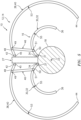
FIG. 6 is a cross-sectional illustration of the aircraft propulsion system ofFIG. 5 configured with one or more actuators for outer cowl doors. -
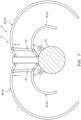
FIG. 7 is a cross-sectional illustration of the aircraft propulsion system ofFIG. 5 configured with one or more actuators for inner cowl doors. -
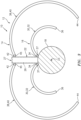
FIG. 8 is a cross-sectional illustration of the aircraft propulsion system ofFIG. 3 configured with one or more alternative linkages outside the wording of the claims. -
FIG. 1 illustrates anaircraft propulsion system 10 for an aircraft such as, but not limited to, a commercial airliner or a cargo plane. Thepropulsion system 10 includes anacelle 12 and a gas turbine engine. This gas turbine engine may be configured as a high-bypass turbofan engine. Alternatively, the gas turbine engine may be configured as any other type of gas turbine engine capable of propelling the aircraft during flight. - The
nacelle 12 is configured to house and provide an aerodynamic cover for the gas turbine engine. Thenacelle 12 ofFIG. 1 includes a nacelleouter structure 14 and a nacelleinner structure 16, whichinner structure 16 may sometimes be referred to as an inner fixed structure (IPS). - Referring to
FIG. 2 , theinner structure 16 covers acore 18 of the gas turbine engine. Thisengine core 18 may include a compressor section, a combustor section and a turbine section. - The
inner structure 16 includes an inner barrel 20 and at least onebifurcation structure 22; e.g., an upper bifurcation cowl. The inner barrel 20 may be a generally cylindrical and/or barrel-shaped cowl that extends circumferentially around and axially along theengine core 18 and/or anaxial centerline 23 of theaircraft propulsion system 10 and/or its gas turbine engine, whichaxial centerline 23 may be coaxial with a rotational axis of the gas turbine engine. The inner barrel 20 at least partially forms an internal compartment 24 (e.g., a core compartment) within thenacelle 12. Thisinternal compartment 24 at least partially or completely houses theengine core 18. Theengine core 18 is thereby arranged within theinternal compartment 24. Thebifurcation structure 22 provides an aerodynamic housing for apylon 26 which mounts theaircraft propulsion system 10 to the aircraft. Thebifurcation structure 22 extends radially between the inner barrel 20 and theouter structure 14. Thebifurcation structure 22 and/or thepylon 26 may each be configured as part of afixed structure 27 of theaircraft propulsion system 10. - The
outer structure 14 covers a fan section (not shown) of the gas turbine engine; e.g., theouter structure 14 covers afan case 29 of the fan section; seeFIG. 1 . Theouter structure 14 covers at least a forward portion of theinner structure 16 and its inner barrel 20 so as to form a bypass duct and an associatedbypass flowpath 28 radially between thestructures outer structure 14 may also be configured with a thrust reverser for redirecting airflow from thebypass flowpath 28 out of thenacelle 12 in a forward and outward direction. The present disclosure, however, is not limited to the foregoing exemplary general nacelle configuration. - Briefly, the bypass duct of
FIG. 2 is configured as an O-Duct. The term "O-duct" may describe a duct through which only a single bifurcation extends between and connects a nacelle outer structure and a nacelle inner structure. By contrast, the term "C-Duct" or "D-duct" may describe a duct through which two bifurcations (e.g., an upper bifurcation and a lower bifurcation) extends between and connect a nacelle outer structure and a nacelle inner structure. Of course, although the exemplary duct shown inFIG. 2 is an O-duct, the present disclosure is not limited to any particular duct configurations. In particular, the present disclosure also contemplates thenacelle 12 having a C-duct or a D-duct. - Referring still to
FIG. 2 , theinner structure 16 is configured with one or more movable (e.g., pivotable) inner structure components 30. These inner structure components 30 are configured as or otherwise include inner cowl doors 32. Each of these inner cowl doors 32 extends circumferentially about theaxial centerline 23. In particular, each inner cowl door 32 extends circumferentially between an inner cowl first (e.g., upper) end 34 and an inner cowl second (e.g., lower)end 36. The inner cowl door 32 is pivotally connected to the fixed structure 27 (e.g., thebifurcation structure 22 and/or the pylon 26), such as at the inner cowlfirst end 34 by, for example, a hinge at apivot point 37. Each inner cowl door 32 is thereby operable to move (e.g., pivot about the pivot point 37) between an inner cowl door closed position (position ofFIG. 2 ) and an inner cowl door open position (position ofFIG. 3 ). Referring again toFIG. 2 , the inner cowl second ends 36 of the inner cowl doors 32 may be configured to latch together so as to at least partially or completely form the inner barrel 20. - The
outer structure 14 is configured with one or more movable (e.g., pivotable) outer structure components 38. These outer structure components 38 are configured as or otherwise include outer cowl doors 40. Each of these outer cowl doors 40 extends circumferentially about theaxial centerline 23. In particular, each outer cowl door 40 extends circumferentially between an outer cowl first (e.g., upper) end 42 and an outer cowl second (e.g., lower)end 44. The outer cowl door 40 is pivotally connected to the fixed structure 27 (e.g., thebifurcation structure 22 and/or the pylon 26), such as at the outer cowlfirst end 42 by, for example, a hinge at apivot point 45. Each outer cowl door 40 is thereby operable to move (e.g., pivot about the pivot point 45) between an outer cowl door closed position (position ofFIG. 2 ) and an outer cowl door open position (position ofFIG. 3 ). Referring again toFIG. 2 , the outer cowl second ends 44 of the outer cowl doors 40 may be configured to latch together so as to at least partially or completely form, for example, a translatable sleeve of theouter structure 14. - Referring to
FIGS. 4 and5 , to assist and/or otherwise facilitate in the opening of and/or the closing of and/or the holding of the components 30 and/or 38 (e.g., the cowl doors 32 and/or 40), thenacelle 12 is configured with one ormore linkages 46. Each of theselinkages 46 is connected to a respective one of the outer structure components 38 (outer cowl doors 40) and a respective one of the inner structure components 30 (inner cowl doors 32). A first (e.g., outer) end 48 of eachlinkage 46 ofFIGS. 4 and5 is moveably (pivotally) connected to the respective outer cowl door 40, for example at a first connection point 49 (e.g., an outer pivot point) via a first pivot joint; e.g., an outer pin connection. A second (e.g., inner) end 50 of eachlinkage 46 ofFIGS. 4 and5 is moveably (pivotally) connected to the respective outer cowl door 40, for example at a second connection point 51 (e.g., an inner pivot point) via a second pivot joint; e.g., an inner pin connection. Eachlinkage 46 extends (e.g., radially) between the respective outer cowl door 40 and the respective inner cowl door 32. In the specific embodiment ofFIGS. 4 and5 , eachlinkage 46 completes a four-bar mechanism between thecomponents 27, 30/32 and 38/40. - Each
linkage 46 is arranged proximate the fixedstructure 27; e.g., thebifurcation structure 22 and/or thepylon 26. Eachlinkage 46, for example, may be arranged closer to the fixedstructure 27 than theends 36 and/or 44. In some embodiments, thefirst connection point 49 is located circumferentially along the component 38, 40 between theend 42 and a circumferential midpoint 53 (e.g., center) of the component 38, 40, whichmidpoint 53 may be located circumferentially (e.g., halfway) along the component 38, 40 between itsends connection point 49 ofFIGS. 4 and5 , for example, is located circumferentially closer to theend 42 than themidpoint 53. In addition or alternatively, thesecond connection point 51 is located circumferentially along the component 30, 32 between theend 34 and a circumferential midpoint 55 (e.g., center) of the component 30, 32, whichmidpoint 55 may be located circumferentially (e.g., halfway) along the component 30, 32 between itsends connection point 51 ofFIGS. 4 and5 , for example, is located circumferentially closer to theend 34 than themidpoint 55. The present disclosure, however, is not limited to such anexemplary linkage 46 location. For example, in other embodiments, thelinkages 46 may be located circumferentially towards themidpoints - Each
linkage 46 is configured to link movement (e.g., pivoting) of the respective outer structure component 38 (e.g., outer cowl door 40) and the respective inner structure component 30 (e.g., inner cowl door 32). In accordance with the present invention, as demonstrated inFIG. 6 , if the outer cowl doors 40 are pulled or otherwise opened (e.g., via one ormore actuators 52 located, for example, outside of the nacelle 12), then thelinkages 46 will pull the inner cowl doors 32 open (e.g., concurrently) with the outer cowl doors 40. In the embodiment ofFIG. 7 , if the inner cowl doors 32 are pushed or otherwise opened (e.g., via one ormore actuators 54 located, for example, within the nacelle (e.g., configured with the engine core 18)), then thelinkages 46 will push the outer cowl doors 40 open (e.g., concurrently) with the inner cowl doors 32. - In some embodiments, referring to
FIGS. 4 and5 , one or eachlinkage 46 may be configured as a single rigid link such as, but not limited to, a push (or pull) rod. Eachlinkage 46 has a longitudinal fixed length. - In some embodiments, referring to
FIG. 8 , one or eachlinkage 46 may be configured with alock 56; e.g., a locking mechanism. In an example outside the wording of the claims, eachlinkage 46 ofFIG. 8 may include two (e.g., fixed or variable length) links 58 and 60 configured to provide an over-center lock when thoselinks linkage 46 may have a longitudinal variable length. - In some embodiments, one or each
linkage 46 may be permanently mounted with the cowl doors 32, 40. In other words, thelinkages 46 may remain mounted with the cowl doors 32, 40 during turbine engine operation. However, in other embodiments, one or eachlinkage 46 may be removably mounted with the cowl doors 32, 40 such that thoselinkages 46 are removed for turbine engine operation. Thus, thelinkages 46 may be installed only for turbine engine maintenance and/or inspection. - While various embodiments of the present invention have been disclosed, it will be apparent to those of ordinary skill in the art that many more embodiments and implementations are possible within the scope of the attached claims.
Claims (12)
- An assembly for an aircraft propulsion system (10), comprising:a fixed structure (27);an inner cowl door (32) extending circumferentially between an inner cowl door first end (34) and an inner cowl door second end (36), the inner cowl door (32) pivotally connected to the fixed structure (27) at the inner cowl door first end (34);an outer cowl door (40) pivotally connected to the fixed structure (27), the outer cowl door (40) radially outboard of and overlapping the inner cowl door (32); anda linkage (46) extending between and movably connected to the inner cowl door (32) and the outer cowl door (40), the linkage (46) pivotally connected to the inner cowl door (32) and pivotally connected to the outer cowl door (40), wherein the linkage (46) is arranged proximate the fixed structure (27),characterized in that:
the linkage (46) has a fixed length and is arranged closer to the fixed structure (27) than to the inner cowl door second end (36), and the linkage (46) is configured to pull against and thereby open the inner cowl door (32) as the outer cowl door (40) is opened. - The assembly of claim 1, whereinthe inner cowl door (32) has an inner cowl door midpoint (55) halfway circumferentially along the inner cowl door (32) between the inner cowl door first end (34) and the inner cowl door second end (36); andthe linkage (46) is movably connected to the inner cowl door (32) at an inner cowl door connection point (51) circumferentially between the inner cowl door midpoint (55) and the inner cowl door first end (34).
- The assembly of claim 2, wherein the inner cowl door connection point (51) is circumferentially closer to the inner cowl door first end (34) than the inner cowl door midpoint (55).
- The assembly of claim 1, 2 or 3, whereinthe outer cowl door (40) extends circumferentially between an outer cowl door first end (42) and an outer cowl door second end (44) with an outer cowl door midpoint (53) halfway circumferentially along the outer cowl door (40) between the outer cowl door first end (42) and the outer cowl door second end (44);the outer cowl door (40) is pivotally connected to the fixed structure (27) at the outer cowl door first end (42); andthe linkage (46) is movably connected to the outer cowl door (40) at an outer cowl door connection point (49) circumferentially between the outer cowl door midpoint (53) and the outer cowl door first end (42).
- The assembly of claim 4, wherein the outer cowl door connection point (49) is circumferentially closer to the outer cowl door first end (42) than the outer cowl door midpoint (53).
- The assembly of any preceding claim, wherein the linkage (46) is configured to push against and thereby open the outer cowl door (40) as the inner cowl door (32) is opened.
- The assembly of any preceding claim, further comprising a lock (56) configured to lock a position of the linkage (46).
- The assembly of any preceding claim, further comprising an inner cowl door actuator (54) configured to push open the inner cowl door (32).
- The assembly of any preceding claim, further comprising an outer cowl door actuator (52) configured to pull open the outer cowl door (40).
- The assembly of any preceding claim, wherein a portion of a bypass flowpath within the aircraft propulsion system (10) is formed by and extends radially between the inner cowl door (32) and the outer cowl door (40).
- The assembly of any preceding claim, further comprising:a nacelle outer structure (14) comprising the outer cowl door (40); anda nacelle inner structure (16) comprising the inner cowl door (32).
- The assembly of claim 1, further comprising:a nacelle inner structure (16) comprising the inner cowl door (32), the inner cowl door (32) pivotally connected to the fixed structure (27) at a first pivot point (37), and the inner cowl door (32) configured to pivot about the first pivot point (37) between an inner cowl door closed position and an inner cowl door open position; anda nacelle outer structure (14) extending circumferentially about and overlapping the nacelle inner structure (16), the nacelle outer structure (14) comprising the outer cowl door (40), the outer cowl door (40) pivotally connected to the fixed structure (27) at a second pivot point (45), and the outer cowl door (40) configured to pivot about the second pivot point (45) between an outer cowl door closed position and an outer cowl door open position,the linkage (46) extending between and pivotally connected to the inner cowl door (32) at an inner cowl door connection point (51) and the outer cowl door (40) at an outer connection point (49), wherein the inner cowl door connection point (51) is located circumferentially along the inner cowl door (32) between an inner cowl door midpoint (55) of the inner cowl door (32) and the first pivot point (37), and/or the outer connection point (49) is located circumferentially along the outer cowl door (40) between an outer cowl door midpoint (53) of the outer cowl door (40) and the second pivot point (45).
Applications Claiming Priority (1)
| Application Number | Priority Date | Filing Date | Title |
|---|---|---|---|
| US201962907813P | 2019-09-30 | 2019-09-30 |
Publications (2)
| Publication Number | Publication Date |
|---|---|
| EP3798134A1 EP3798134A1 (en) | 2021-03-31 |
| EP3798134B1 true EP3798134B1 (en) | 2024-05-29 |
Family
ID=72709224
Family Applications (1)
| Application Number | Title | Priority Date | Filing Date |
|---|---|---|---|
| EP20199457.1A Active EP3798134B1 (en) | 2019-09-30 | 2020-09-30 | Linkage(s) between inner and outer cowl doors |
Country Status (2)
| Country | Link |
|---|---|
| US (1) | US11511874B2 (en) |
| EP (1) | EP3798134B1 (en) |
Families Citing this family (3)
| Publication number | Priority date | Publication date | Assignee | Title |
|---|---|---|---|---|
| EP3798133B1 (en) * | 2019-09-30 | 2023-06-21 | Rohr, Inc. | Linkage supporting a door of an aircraft propulsion system |
| US12214892B2 (en) * | 2022-08-20 | 2025-02-04 | Hamilton Sundstrand Corporation | One-way speed limiter for a power door opening system for an aircraft |
| FR3160676A1 (en) * | 2024-03-27 | 2025-10-03 | Airbus Operations | Aircraft turbojet engine comprising at least one structural panel connected to a structure by at least one removable connection and at least one articulation |
Family Cites Families (18)
| Publication number | Priority date | Publication date | Assignee | Title |
|---|---|---|---|---|
| FR2379434A1 (en) | 1977-02-08 | 1978-09-01 | Snecma | TURBOREACTOR NACELLE SLIDING COVER LOCKING SYSTEM |
| US4385423A (en) | 1980-12-22 | 1983-05-31 | The Boeing Company | Over-center latching coupling |
| FR2560854B1 (en) * | 1984-03-07 | 1986-09-12 | Snecma | STRUCTURAL HOODS PARTICIPATING IN THE ASSEMBLY RIGIDITY OF A TURBO-JET |
| US4679750A (en) * | 1984-06-20 | 1987-07-14 | The Boeing Company | Latch system |
| US4585189A (en) * | 1984-10-22 | 1986-04-29 | Lockheed Corporation | Counterbalanced cowling assembly for a pylon-mounted engine and nacelle therefor |
| BR0315201A (en) | 2002-10-11 | 2005-08-16 | Nordam Group Inc | Double Fold Boost Inverter |
| GB2483908B (en) * | 2010-09-24 | 2012-07-11 | Short Brothers Plc | Nacelle |
| US9650917B2 (en) * | 2010-09-24 | 2017-05-16 | Short Brothers Plc | Nacelle with hinged cowl doors enabling access to the engine |
| US20150275766A1 (en) | 2012-10-10 | 2015-10-01 | United Technologies Corporation | Geared turbine engine with a d-duct and a thrust reverser |
| US9435293B2 (en) | 2013-02-22 | 2016-09-06 | United Technologies Corporation | Full ring sliding nacelle with thrust reverser |
| US9221545B2 (en) * | 2013-04-03 | 2015-12-29 | The Boeing Company | Aircraft nacelle assemblies |
| CN110259599B (en) * | 2013-10-07 | 2021-11-09 | 罗尔公司 | Hybrid internal fixation structure with metal and composite construction |
| FR3037039B1 (en) * | 2015-06-03 | 2017-06-02 | Aircelle Sa | DEVICE FOR LOCKING PIVOTING HOODS OF A PUSH INVERTER |
| US10041443B2 (en) | 2015-06-09 | 2018-08-07 | The Boeing Company | Thrust reverser apparatus and method |
| US10267060B2 (en) | 2016-12-21 | 2019-04-23 | The Boeing Company | Apparatuses and methods for cowl latch indication |
| US10618664B2 (en) | 2017-06-16 | 2020-04-14 | Rohr, Inc. | Self-latching nacelle |
| FR3076323B1 (en) * | 2017-12-28 | 2020-01-10 | Safran Nacelles | GRID DRIVER INVERTER FOR TURBOJET |
| FR3078111B1 (en) * | 2018-02-22 | 2020-01-17 | Airbus Sas | TURBOREACTOR COMPRISING A NACELLE EQUIPPED WITH A REVERSING SYSTEM COMPRISING EXTERNAL AND INTERIOR DOORS |
-
2020
- 2020-09-30 US US17/037,896 patent/US11511874B2/en active Active
- 2020-09-30 EP EP20199457.1A patent/EP3798134B1/en active Active
Also Published As
| Publication number | Publication date |
|---|---|
| US11511874B2 (en) | 2022-11-29 |
| US20210094697A1 (en) | 2021-04-01 |
| EP3798134A1 (en) | 2021-03-31 |
Similar Documents
| Publication | Publication Date | Title |
|---|---|---|
| US8713910B2 (en) | Integrated thrust reverser/pylon assembly | |
| EP3626959B1 (en) | Thrust reverser with blocker door folding linkage | |
| EP3871979B1 (en) | Structural panel with integrated coupler | |
| EP3798133B1 (en) | Linkage supporting a door of an aircraft propulsion system | |
| EP2562405B1 (en) | Gas turbine engine access door | |
| US20180372024A1 (en) | Thrust Reverser System Having Limited Aerodynamic Disturbance | |
| US11511874B2 (en) | Linkage(s) between inner and outer cowl doors | |
| EP3591204B1 (en) | Thrust reverser with displaceable trailing edge body | |
| EP3489496B1 (en) | Pre-exit pivot door thrust reverser | |
| US10697396B2 (en) | Fan cowl mounted to thrust reverser | |
| EP4163487B1 (en) | Thrust reverser system with hidden turning door | |
| US20100193628A1 (en) | Continuous composite fan duct and thrust reverser | |
| US20120247571A1 (en) | Jet engine nacelle rear assembly | |
| EP3943737B1 (en) | Hidden door thrust reverser system for an aircraft propulsion system | |
| US11512641B2 (en) | Upper axial retention for a cascade-type thrust reverser with sliding vanes of D-shaped structure | |
| US20170283081A1 (en) | Securing a translating fanlet for an aircraft propulsion system nacelle | |
| US12385448B2 (en) | Thrust reverser with lost motion device | |
| US12158122B2 (en) | Nacelle for an aircraft propulsion assembly comprising a flap for closing a recess for the passage of an actuator | |
| US12612171B2 (en) | Multi-system thrust reverser for aircraft propulsion system | |
| EP4123152B1 (en) | Thrust reverser system latch assembly and method of operating same | |
| US12104556B1 (en) | Blocker door retention assembly for an aircraft propulsion system thrust reverser |
Legal Events
| Date | Code | Title | Description |
|---|---|---|---|
| PUAI | Public reference made under article 153(3) epc to a published international application that has entered the european phase |
Free format text: ORIGINAL CODE: 0009012 |
|
| STAA | Information on the status of an ep patent application or granted ep patent |
Free format text: STATUS: THE APPLICATION HAS BEEN PUBLISHED |
|
| AK | Designated contracting states |
Kind code of ref document: A1 Designated state(s): AL AT BE BG CH CY CZ DE DK EE ES FI FR GB GR HR HU IE IS IT LI LT LU LV MC MK MT NL NO PL PT RO RS SE SI SK SM TR |
|
| AX | Request for extension of the european patent |
Extension state: BA ME |
|
| STAA | Information on the status of an ep patent application or granted ep patent |
Free format text: STATUS: REQUEST FOR EXAMINATION WAS MADE |
|
| 17P | Request for examination filed |
Effective date: 20210930 |
|
| RBV | Designated contracting states (corrected) |
Designated state(s): AL AT BE BG CH CY CZ DE DK EE ES FI FR GB GR HR HU IE IS IT LI LT LU LV MC MK MT NL NO PL PT RO RS SE SI SK SM TR |
|
| STAA | Information on the status of an ep patent application or granted ep patent |
Free format text: STATUS: EXAMINATION IS IN PROGRESS |
|
| 17Q | First examination report despatched |
Effective date: 20220726 |
|
| GRAP | Despatch of communication of intention to grant a patent |
Free format text: ORIGINAL CODE: EPIDOSNIGR1 |
|
| STAA | Information on the status of an ep patent application or granted ep patent |
Free format text: STATUS: GRANT OF PATENT IS INTENDED |
|
| INTG | Intention to grant announced |
Effective date: 20231219 |
|
| GRAS | Grant fee paid |
Free format text: ORIGINAL CODE: EPIDOSNIGR3 |
|
| GRAA | (expected) grant |
Free format text: ORIGINAL CODE: 0009210 |
|
| STAA | Information on the status of an ep patent application or granted ep patent |
Free format text: STATUS: THE PATENT HAS BEEN GRANTED |
|
| AK | Designated contracting states |
Kind code of ref document: B1 Designated state(s): AL AT BE BG CH CY CZ DE DK EE ES FI FR GB GR HR HU IE IS IT LI LT LU LV MC MK MT NL NO PL PT RO RS SE SI SK SM TR |
|
| REG | Reference to a national code |
Ref country code: CH Ref legal event code: EP |
|
| REG | Reference to a national code |
Ref country code: IE Ref legal event code: FG4D |
|
| REG | Reference to a national code |
Ref country code: DE Ref legal event code: R096 Ref document number: 602020031553 Country of ref document: DE |
|
| REG | Reference to a national code |
Ref country code: LT Ref legal event code: MG9D |
|
| REG | Reference to a national code |
Ref country code: NL Ref legal event code: MP Effective date: 20240529 |
|
| PG25 | Lapsed in a contracting state [announced via postgrant information from national office to epo] |
Ref country code: IS Free format text: LAPSE BECAUSE OF FAILURE TO SUBMIT A TRANSLATION OF THE DESCRIPTION OR TO PAY THE FEE WITHIN THE PRESCRIBED TIME-LIMIT Effective date: 20240929 |
|
| PG25 | Lapsed in a contracting state [announced via postgrant information from national office to epo] |
Ref country code: BG Free format text: LAPSE BECAUSE OF FAILURE TO SUBMIT A TRANSLATION OF THE DESCRIPTION OR TO PAY THE FEE WITHIN THE PRESCRIBED TIME-LIMIT Effective date: 20240529 |
|
| PG25 | Lapsed in a contracting state [announced via postgrant information from national office to epo] |
Ref country code: FI Free format text: LAPSE BECAUSE OF FAILURE TO SUBMIT A TRANSLATION OF THE DESCRIPTION OR TO PAY THE FEE WITHIN THE PRESCRIBED TIME-LIMIT Effective date: 20240529 Ref country code: HR Free format text: LAPSE BECAUSE OF FAILURE TO SUBMIT A TRANSLATION OF THE DESCRIPTION OR TO PAY THE FEE WITHIN THE PRESCRIBED TIME-LIMIT Effective date: 20240529 |
|
| PG25 | Lapsed in a contracting state [announced via postgrant information from national office to epo] |
Ref country code: GR Free format text: LAPSE BECAUSE OF FAILURE TO SUBMIT A TRANSLATION OF THE DESCRIPTION OR TO PAY THE FEE WITHIN THE PRESCRIBED TIME-LIMIT Effective date: 20240830 |
|
| REG | Reference to a national code |
Ref country code: AT Ref legal event code: MK05 Ref document number: 1690442 Country of ref document: AT Kind code of ref document: T Effective date: 20240529 |
|
| PG25 | Lapsed in a contracting state [announced via postgrant information from national office to epo] |
Ref country code: ES Free format text: LAPSE BECAUSE OF FAILURE TO SUBMIT A TRANSLATION OF THE DESCRIPTION OR TO PAY THE FEE WITHIN THE PRESCRIBED TIME-LIMIT Effective date: 20240529 |
|
| PG25 | Lapsed in a contracting state [announced via postgrant information from national office to epo] |
Ref country code: AT Free format text: LAPSE BECAUSE OF FAILURE TO SUBMIT A TRANSLATION OF THE DESCRIPTION OR TO PAY THE FEE WITHIN THE PRESCRIBED TIME-LIMIT Effective date: 20240529 |
|
| PG25 | Lapsed in a contracting state [announced via postgrant information from national office to epo] |
Ref country code: PL Free format text: LAPSE BECAUSE OF FAILURE TO SUBMIT A TRANSLATION OF THE DESCRIPTION OR TO PAY THE FEE WITHIN THE PRESCRIBED TIME-LIMIT Effective date: 20240529 |
|
| PG25 | Lapsed in a contracting state [announced via postgrant information from national office to epo] |
Ref country code: LV Free format text: LAPSE BECAUSE OF FAILURE TO SUBMIT A TRANSLATION OF THE DESCRIPTION OR TO PAY THE FEE WITHIN THE PRESCRIBED TIME-LIMIT Effective date: 20240529 |
|
| PG25 | Lapsed in a contracting state [announced via postgrant information from national office to epo] |
Ref country code: PL Free format text: LAPSE BECAUSE OF FAILURE TO SUBMIT A TRANSLATION OF THE DESCRIPTION OR TO PAY THE FEE WITHIN THE PRESCRIBED TIME-LIMIT Effective date: 20240529 Ref country code: NO Free format text: LAPSE BECAUSE OF FAILURE TO SUBMIT A TRANSLATION OF THE DESCRIPTION OR TO PAY THE FEE WITHIN THE PRESCRIBED TIME-LIMIT Effective date: 20240829 Ref country code: LV Free format text: LAPSE BECAUSE OF FAILURE TO SUBMIT A TRANSLATION OF THE DESCRIPTION OR TO PAY THE FEE WITHIN THE PRESCRIBED TIME-LIMIT Effective date: 20240529 Ref country code: IS Free format text: LAPSE BECAUSE OF FAILURE TO SUBMIT A TRANSLATION OF THE DESCRIPTION OR TO PAY THE FEE WITHIN THE PRESCRIBED TIME-LIMIT Effective date: 20240929 Ref country code: HR Free format text: LAPSE BECAUSE OF FAILURE TO SUBMIT A TRANSLATION OF THE DESCRIPTION OR TO PAY THE FEE WITHIN THE PRESCRIBED TIME-LIMIT Effective date: 20240529 Ref country code: GR Free format text: LAPSE BECAUSE OF FAILURE TO SUBMIT A TRANSLATION OF THE DESCRIPTION OR TO PAY THE FEE WITHIN THE PRESCRIBED TIME-LIMIT Effective date: 20240830 Ref country code: FI Free format text: LAPSE BECAUSE OF FAILURE TO SUBMIT A TRANSLATION OF THE DESCRIPTION OR TO PAY THE FEE WITHIN THE PRESCRIBED TIME-LIMIT Effective date: 20240529 Ref country code: ES Free format text: LAPSE BECAUSE OF FAILURE TO SUBMIT A TRANSLATION OF THE DESCRIPTION OR TO PAY THE FEE WITHIN THE PRESCRIBED TIME-LIMIT Effective date: 20240529 Ref country code: BG Free format text: LAPSE BECAUSE OF FAILURE TO SUBMIT A TRANSLATION OF THE DESCRIPTION OR TO PAY THE FEE WITHIN THE PRESCRIBED TIME-LIMIT Effective date: 20240529 Ref country code: AT Free format text: LAPSE BECAUSE OF FAILURE TO SUBMIT A TRANSLATION OF THE DESCRIPTION OR TO PAY THE FEE WITHIN THE PRESCRIBED TIME-LIMIT Effective date: 20240529 Ref country code: RS Free format text: LAPSE BECAUSE OF FAILURE TO SUBMIT A TRANSLATION OF THE DESCRIPTION OR TO PAY THE FEE WITHIN THE PRESCRIBED TIME-LIMIT Effective date: 20240829 |
|
| PG25 | Lapsed in a contracting state [announced via postgrant information from national office to epo] |
Ref country code: NL Free format text: LAPSE BECAUSE OF FAILURE TO SUBMIT A TRANSLATION OF THE DESCRIPTION OR TO PAY THE FEE WITHIN THE PRESCRIBED TIME-LIMIT Effective date: 20240529 |
|
| PG25 | Lapsed in a contracting state [announced via postgrant information from national office to epo] |
Ref country code: NL Free format text: LAPSE BECAUSE OF FAILURE TO SUBMIT A TRANSLATION OF THE DESCRIPTION OR TO PAY THE FEE WITHIN THE PRESCRIBED TIME-LIMIT Effective date: 20240529 |
|
| PG25 | Lapsed in a contracting state [announced via postgrant information from national office to epo] |
Ref country code: DK Free format text: LAPSE BECAUSE OF FAILURE TO SUBMIT A TRANSLATION OF THE DESCRIPTION OR TO PAY THE FEE WITHIN THE PRESCRIBED TIME-LIMIT Effective date: 20240529 |
|
| PG25 | Lapsed in a contracting state [announced via postgrant information from national office to epo] |
Ref country code: EE Free format text: LAPSE BECAUSE OF FAILURE TO SUBMIT A TRANSLATION OF THE DESCRIPTION OR TO PAY THE FEE WITHIN THE PRESCRIBED TIME-LIMIT Effective date: 20240529 |
|
| PG25 | Lapsed in a contracting state [announced via postgrant information from national office to epo] |
Ref country code: CZ Free format text: LAPSE BECAUSE OF FAILURE TO SUBMIT A TRANSLATION OF THE DESCRIPTION OR TO PAY THE FEE WITHIN THE PRESCRIBED TIME-LIMIT Effective date: 20240529 |
|
| PG25 | Lapsed in a contracting state [announced via postgrant information from national office to epo] |
Ref country code: SK Free format text: LAPSE BECAUSE OF FAILURE TO SUBMIT A TRANSLATION OF THE DESCRIPTION OR TO PAY THE FEE WITHIN THE PRESCRIBED TIME-LIMIT Effective date: 20240529 Ref country code: RO Free format text: LAPSE BECAUSE OF FAILURE TO SUBMIT A TRANSLATION OF THE DESCRIPTION OR TO PAY THE FEE WITHIN THE PRESCRIBED TIME-LIMIT Effective date: 20240529 |
|
| PG25 | Lapsed in a contracting state [announced via postgrant information from national office to epo] |
Ref country code: SM Free format text: LAPSE BECAUSE OF FAILURE TO SUBMIT A TRANSLATION OF THE DESCRIPTION OR TO PAY THE FEE WITHIN THE PRESCRIBED TIME-LIMIT Effective date: 20240529 |
|
| PG25 | Lapsed in a contracting state [announced via postgrant information from national office to epo] |
Ref country code: SM Free format text: LAPSE BECAUSE OF FAILURE TO SUBMIT A TRANSLATION OF THE DESCRIPTION OR TO PAY THE FEE WITHIN THE PRESCRIBED TIME-LIMIT Effective date: 20240529 Ref country code: SK Free format text: LAPSE BECAUSE OF FAILURE TO SUBMIT A TRANSLATION OF THE DESCRIPTION OR TO PAY THE FEE WITHIN THE PRESCRIBED TIME-LIMIT Effective date: 20240529 Ref country code: RO Free format text: LAPSE BECAUSE OF FAILURE TO SUBMIT A TRANSLATION OF THE DESCRIPTION OR TO PAY THE FEE WITHIN THE PRESCRIBED TIME-LIMIT Effective date: 20240529 Ref country code: EE Free format text: LAPSE BECAUSE OF FAILURE TO SUBMIT A TRANSLATION OF THE DESCRIPTION OR TO PAY THE FEE WITHIN THE PRESCRIBED TIME-LIMIT Effective date: 20240529 Ref country code: DK Free format text: LAPSE BECAUSE OF FAILURE TO SUBMIT A TRANSLATION OF THE DESCRIPTION OR TO PAY THE FEE WITHIN THE PRESCRIBED TIME-LIMIT Effective date: 20240529 Ref country code: CZ Free format text: LAPSE BECAUSE OF FAILURE TO SUBMIT A TRANSLATION OF THE DESCRIPTION OR TO PAY THE FEE WITHIN THE PRESCRIBED TIME-LIMIT Effective date: 20240529 |
|
| PG25 | Lapsed in a contracting state [announced via postgrant information from national office to epo] |
Ref country code: IT Free format text: LAPSE BECAUSE OF FAILURE TO SUBMIT A TRANSLATION OF THE DESCRIPTION OR TO PAY THE FEE WITHIN THE PRESCRIBED TIME-LIMIT Effective date: 20240529 |
|
| REG | Reference to a national code |
Ref country code: DE Ref legal event code: R097 Ref document number: 602020031553 Country of ref document: DE |
|
| PLBE | No opposition filed within time limit |
Free format text: ORIGINAL CODE: 0009261 |
|
| STAA | Information on the status of an ep patent application or granted ep patent |
Free format text: STATUS: NO OPPOSITION FILED WITHIN TIME LIMIT |
|
| PG25 | Lapsed in a contracting state [announced via postgrant information from national office to epo] |
Ref country code: SI Free format text: LAPSE BECAUSE OF FAILURE TO SUBMIT A TRANSLATION OF THE DESCRIPTION OR TO PAY THE FEE WITHIN THE PRESCRIBED TIME-LIMIT Effective date: 20240529 Ref country code: MC Free format text: LAPSE BECAUSE OF FAILURE TO SUBMIT A TRANSLATION OF THE DESCRIPTION OR TO PAY THE FEE WITHIN THE PRESCRIBED TIME-LIMIT Effective date: 20240529 |
|
| REG | Reference to a national code |
Ref country code: CH Ref legal event code: PL |
|
| 26N | No opposition filed |
Effective date: 20250303 |
|
| PG25 | Lapsed in a contracting state [announced via postgrant information from national office to epo] |
Ref country code: LU Free format text: LAPSE BECAUSE OF NON-PAYMENT OF DUE FEES Effective date: 20240930 |
|
| REG | Reference to a national code |
Ref country code: BE Ref legal event code: MM Effective date: 20240930 |
|
| PG25 | Lapsed in a contracting state [announced via postgrant information from national office to epo] |
Ref country code: BE Free format text: LAPSE BECAUSE OF NON-PAYMENT OF DUE FEES Effective date: 20240930 |
|
| PG25 | Lapsed in a contracting state [announced via postgrant information from national office to epo] |
Ref country code: CH Free format text: LAPSE BECAUSE OF NON-PAYMENT OF DUE FEES Effective date: 20240930 |
|
| PG25 | Lapsed in a contracting state [announced via postgrant information from national office to epo] |
Ref country code: IE Free format text: LAPSE BECAUSE OF NON-PAYMENT OF DUE FEES Effective date: 20240930 |
|
| PG25 | Lapsed in a contracting state [announced via postgrant information from national office to epo] |
Ref country code: SE Free format text: LAPSE BECAUSE OF FAILURE TO SUBMIT A TRANSLATION OF THE DESCRIPTION OR TO PAY THE FEE WITHIN THE PRESCRIBED TIME-LIMIT Effective date: 20240529 |
|
| PGFP | Annual fee paid to national office [announced via postgrant information from national office to epo] |
Ref country code: DE Payment date: 20250820 Year of fee payment: 6 |
|
| PGFP | Annual fee paid to national office [announced via postgrant information from national office to epo] |
Ref country code: GB Payment date: 20250822 Year of fee payment: 6 |
|
| PGFP | Annual fee paid to national office [announced via postgrant information from national office to epo] |
Ref country code: FR Payment date: 20250820 Year of fee payment: 6 |
|
| PG25 | Lapsed in a contracting state [announced via postgrant information from national office to epo] |
Ref country code: PT Free format text: LAPSE BECAUSE OF NON-PAYMENT OF DUE FEES Effective date: 20240529 |
|
| PG25 | Lapsed in a contracting state [announced via postgrant information from national office to epo] |
Ref country code: CY Free format text: LAPSE BECAUSE OF FAILURE TO SUBMIT A TRANSLATION OF THE DESCRIPTION OR TO PAY THE FEE WITHIN THE PRESCRIBED TIME-LIMIT; INVALID AB INITIO Effective date: 20200930 |
|
| PG25 | Lapsed in a contracting state [announced via postgrant information from national office to epo] |
Ref country code: HU Free format text: LAPSE BECAUSE OF FAILURE TO SUBMIT A TRANSLATION OF THE DESCRIPTION OR TO PAY THE FEE WITHIN THE PRESCRIBED TIME-LIMIT; INVALID AB INITIO Effective date: 20200930 |