EP3798056A1 - Vehicle comprising a rear combination lamp comprising a display - Google Patents
Vehicle comprising a rear combination lamp comprising a display Download PDFInfo
- Publication number
- EP3798056A1 EP3798056A1 EP20207501.6A EP20207501A EP3798056A1 EP 3798056 A1 EP3798056 A1 EP 3798056A1 EP 20207501 A EP20207501 A EP 20207501A EP 3798056 A1 EP3798056 A1 EP 3798056A1
- Authority
- EP
- European Patent Office
- Prior art keywords
- vehicle
- display
- information
- processor
- image
- Prior art date
- Legal status (The legal status is an assumption and is not a legal conclusion. Google has not performed a legal analysis and makes no representation as to the accuracy of the status listed.)
- Pending
Links
- 239000005357 flat glass Substances 0.000 claims description 12
- 238000010586 diagram Methods 0.000 description 63
- 238000004891 communication Methods 0.000 description 58
- 238000001514 detection method Methods 0.000 description 57
- 230000008921 facial expression Effects 0.000 description 22
- 230000006870 function Effects 0.000 description 22
- 238000012545 processing Methods 0.000 description 15
- 238000000034 method Methods 0.000 description 12
- 238000013461 design Methods 0.000 description 11
- 206010039203 Road traffic accident Diseases 0.000 description 8
- 230000001133 acceleration Effects 0.000 description 8
- 238000010276 construction Methods 0.000 description 8
- 230000008451 emotion Effects 0.000 description 7
- 239000000446 fuel Substances 0.000 description 7
- 238000005516 engineering process Methods 0.000 description 6
- 230000003287 optical effect Effects 0.000 description 5
- 230000007423 decrease Effects 0.000 description 4
- 239000007788 liquid Substances 0.000 description 4
- 239000010705 motor oil Substances 0.000 description 4
- 239000003921 oil Substances 0.000 description 4
- 230000005236 sound signal Effects 0.000 description 4
- 239000000725 suspension Substances 0.000 description 4
- 238000004378 air conditioning Methods 0.000 description 3
- 238000003491 array Methods 0.000 description 3
- 239000004973 liquid crystal related substance Substances 0.000 description 3
- 238000005259 measurement Methods 0.000 description 3
- 230000004397 blinking Effects 0.000 description 2
- 239000000470 constituent Substances 0.000 description 2
- 230000001815 facial effect Effects 0.000 description 2
- 230000007774 longterm Effects 0.000 description 2
- 230000004044 response Effects 0.000 description 2
- 235000004522 Pentaglottis sempervirens Nutrition 0.000 description 1
- 230000003321 amplification Effects 0.000 description 1
- 238000004364 calculation method Methods 0.000 description 1
- 238000002485 combustion reaction Methods 0.000 description 1
- 230000000694 effects Effects 0.000 description 1
- 230000005611 electricity Effects 0.000 description 1
- 238000005401 electroluminescence Methods 0.000 description 1
- 239000002803 fossil fuel Substances 0.000 description 1
- 210000003128 head Anatomy 0.000 description 1
- 238000002156 mixing Methods 0.000 description 1
- 230000007935 neutral effect Effects 0.000 description 1
- 238000003199 nucleic acid amplification method Methods 0.000 description 1
- 239000004065 semiconductor Substances 0.000 description 1
- 239000010409 thin film Substances 0.000 description 1
- XLYOFNOQVPJJNP-UHFFFAOYSA-N water Substances O XLYOFNOQVPJJNP-UHFFFAOYSA-N 0.000 description 1
Images


Classifications
-
- F—MECHANICAL ENGINEERING; LIGHTING; HEATING; WEAPONS; BLASTING
- F21—LIGHTING
- F21S—NON-PORTABLE LIGHTING DEVICES; SYSTEMS THEREOF; VEHICLE LIGHTING DEVICES SPECIALLY ADAPTED FOR VEHICLE EXTERIORS
- F21S43/00—Signalling devices specially adapted for vehicle exteriors, e.g. brake lamps, direction indicator lights or reversing lights
-
- B—PERFORMING OPERATIONS; TRANSPORTING
- B60—VEHICLES IN GENERAL
- B60K—ARRANGEMENT OR MOUNTING OF PROPULSION UNITS OR OF TRANSMISSIONS IN VEHICLES; ARRANGEMENT OR MOUNTING OF PLURAL DIVERSE PRIME-MOVERS IN VEHICLES; AUXILIARY DRIVES FOR VEHICLES; INSTRUMENTATION OR DASHBOARDS FOR VEHICLES; ARRANGEMENTS IN CONNECTION WITH COOLING, AIR INTAKE, GAS EXHAUST OR FUEL SUPPLY OF PROPULSION UNITS IN VEHICLES
- B60K35/00—Arrangement of adaptations of instruments
-
- B—PERFORMING OPERATIONS; TRANSPORTING
- B60—VEHICLES IN GENERAL
- B60Q—ARRANGEMENT OF SIGNALLING OR LIGHTING DEVICES, THE MOUNTING OR SUPPORTING THEREOF OR CIRCUITS THEREFOR, FOR VEHICLES IN GENERAL
- B60Q1/00—Arrangement of optical signalling or lighting devices, the mounting or supporting thereof or circuits therefor
- B60Q1/26—Arrangement of optical signalling or lighting devices, the mounting or supporting thereof or circuits therefor the devices being primarily intended to indicate the vehicle, or parts thereof, or to give signals, to other traffic
-
- B60K35/10—
-
- B60K35/28—
-
- B60K35/29—
-
- B60K35/60—
-
- B60K35/65—
-
- B—PERFORMING OPERATIONS; TRANSPORTING
- B60—VEHICLES IN GENERAL
- B60Q—ARRANGEMENT OF SIGNALLING OR LIGHTING DEVICES, THE MOUNTING OR SUPPORTING THEREOF OR CIRCUITS THEREFOR, FOR VEHICLES IN GENERAL
- B60Q1/00—Arrangement of optical signalling or lighting devices, the mounting or supporting thereof or circuits therefor
- B60Q1/0076—Switches therefor
-
- B—PERFORMING OPERATIONS; TRANSPORTING
- B60—VEHICLES IN GENERAL
- B60Q—ARRANGEMENT OF SIGNALLING OR LIGHTING DEVICES, THE MOUNTING OR SUPPORTING THEREOF OR CIRCUITS THEREFOR, FOR VEHICLES IN GENERAL
- B60Q1/00—Arrangement of optical signalling or lighting devices, the mounting or supporting thereof or circuits therefor
- B60Q1/02—Arrangement of optical signalling or lighting devices, the mounting or supporting thereof or circuits therefor the devices being primarily intended to illuminate the way ahead or to illuminate other areas of way or environments
- B60Q1/22—Arrangement of optical signalling or lighting devices, the mounting or supporting thereof or circuits therefor the devices being primarily intended to illuminate the way ahead or to illuminate other areas of way or environments for reverse drive
-
- B—PERFORMING OPERATIONS; TRANSPORTING
- B60—VEHICLES IN GENERAL
- B60Q—ARRANGEMENT OF SIGNALLING OR LIGHTING DEVICES, THE MOUNTING OR SUPPORTING THEREOF OR CIRCUITS THEREFOR, FOR VEHICLES IN GENERAL
- B60Q1/00—Arrangement of optical signalling or lighting devices, the mounting or supporting thereof or circuits therefor
- B60Q1/26—Arrangement of optical signalling or lighting devices, the mounting or supporting thereof or circuits therefor the devices being primarily intended to indicate the vehicle, or parts thereof, or to give signals, to other traffic
- B60Q1/2603—Attenuation of the light according to ambient luminiosity, e.g. for braking or direction indicating lamps
-
- B—PERFORMING OPERATIONS; TRANSPORTING
- B60—VEHICLES IN GENERAL
- B60Q—ARRANGEMENT OF SIGNALLING OR LIGHTING DEVICES, THE MOUNTING OR SUPPORTING THEREOF OR CIRCUITS THEREFOR, FOR VEHICLES IN GENERAL
- B60Q1/00—Arrangement of optical signalling or lighting devices, the mounting or supporting thereof or circuits therefor
- B60Q1/26—Arrangement of optical signalling or lighting devices, the mounting or supporting thereof or circuits therefor the devices being primarily intended to indicate the vehicle, or parts thereof, or to give signals, to other traffic
- B60Q1/2607—Arrangement of optical signalling or lighting devices, the mounting or supporting thereof or circuits therefor the devices being primarily intended to indicate the vehicle, or parts thereof, or to give signals, to other traffic comprising at least two indicating lamps
-
- B—PERFORMING OPERATIONS; TRANSPORTING
- B60—VEHICLES IN GENERAL
- B60Q—ARRANGEMENT OF SIGNALLING OR LIGHTING DEVICES, THE MOUNTING OR SUPPORTING THEREOF OR CIRCUITS THEREFOR, FOR VEHICLES IN GENERAL
- B60Q1/00—Arrangement of optical signalling or lighting devices, the mounting or supporting thereof or circuits therefor
- B60Q1/26—Arrangement of optical signalling or lighting devices, the mounting or supporting thereof or circuits therefor the devices being primarily intended to indicate the vehicle, or parts thereof, or to give signals, to other traffic
- B60Q1/30—Arrangement of optical signalling or lighting devices, the mounting or supporting thereof or circuits therefor the devices being primarily intended to indicate the vehicle, or parts thereof, or to give signals, to other traffic for indicating rear of vehicle, e.g. by means of reflecting surfaces
- B60Q1/302—Arrangement of optical signalling or lighting devices, the mounting or supporting thereof or circuits therefor the devices being primarily intended to indicate the vehicle, or parts thereof, or to give signals, to other traffic for indicating rear of vehicle, e.g. by means of reflecting surfaces mounted in the vicinity, e.g. in the middle, of a rear window
-
- B—PERFORMING OPERATIONS; TRANSPORTING
- B60—VEHICLES IN GENERAL
- B60Q—ARRANGEMENT OF SIGNALLING OR LIGHTING DEVICES, THE MOUNTING OR SUPPORTING THEREOF OR CIRCUITS THEREFOR, FOR VEHICLES IN GENERAL
- B60Q1/00—Arrangement of optical signalling or lighting devices, the mounting or supporting thereof or circuits therefor
- B60Q1/26—Arrangement of optical signalling or lighting devices, the mounting or supporting thereof or circuits therefor the devices being primarily intended to indicate the vehicle, or parts thereof, or to give signals, to other traffic
- B60Q1/34—Arrangement of optical signalling or lighting devices, the mounting or supporting thereof or circuits therefor the devices being primarily intended to indicate the vehicle, or parts thereof, or to give signals, to other traffic for indicating change of drive direction
-
- B—PERFORMING OPERATIONS; TRANSPORTING
- B60—VEHICLES IN GENERAL
- B60Q—ARRANGEMENT OF SIGNALLING OR LIGHTING DEVICES, THE MOUNTING OR SUPPORTING THEREOF OR CIRCUITS THEREFOR, FOR VEHICLES IN GENERAL
- B60Q1/00—Arrangement of optical signalling or lighting devices, the mounting or supporting thereof or circuits therefor
- B60Q1/26—Arrangement of optical signalling or lighting devices, the mounting or supporting thereof or circuits therefor the devices being primarily intended to indicate the vehicle, or parts thereof, or to give signals, to other traffic
- B60Q1/44—Arrangement of optical signalling or lighting devices, the mounting or supporting thereof or circuits therefor the devices being primarily intended to indicate the vehicle, or parts thereof, or to give signals, to other traffic for indicating braking action or preparation for braking, e.g. by detection of the foot approaching the brake pedal
-
- B—PERFORMING OPERATIONS; TRANSPORTING
- B60—VEHICLES IN GENERAL
- B60Q—ARRANGEMENT OF SIGNALLING OR LIGHTING DEVICES, THE MOUNTING OR SUPPORTING THEREOF OR CIRCUITS THEREFOR, FOR VEHICLES IN GENERAL
- B60Q1/00—Arrangement of optical signalling or lighting devices, the mounting or supporting thereof or circuits therefor
- B60Q1/26—Arrangement of optical signalling or lighting devices, the mounting or supporting thereof or circuits therefor the devices being primarily intended to indicate the vehicle, or parts thereof, or to give signals, to other traffic
- B60Q1/48—Arrangement of optical signalling or lighting devices, the mounting or supporting thereof or circuits therefor the devices being primarily intended to indicate the vehicle, or parts thereof, or to give signals, to other traffic for parking purposes
- B60Q1/486—Arrangement of optical signalling or lighting devices, the mounting or supporting thereof or circuits therefor the devices being primarily intended to indicate the vehicle, or parts thereof, or to give signals, to other traffic for parking purposes for indicating that vehicle is in a parked state
-
- B—PERFORMING OPERATIONS; TRANSPORTING
- B60—VEHICLES IN GENERAL
- B60Q—ARRANGEMENT OF SIGNALLING OR LIGHTING DEVICES, THE MOUNTING OR SUPPORTING THEREOF OR CIRCUITS THEREFOR, FOR VEHICLES IN GENERAL
- B60Q1/00—Arrangement of optical signalling or lighting devices, the mounting or supporting thereof or circuits therefor
- B60Q1/26—Arrangement of optical signalling or lighting devices, the mounting or supporting thereof or circuits therefor the devices being primarily intended to indicate the vehicle, or parts thereof, or to give signals, to other traffic
- B60Q1/50—Arrangement of optical signalling or lighting devices, the mounting or supporting thereof or circuits therefor the devices being primarily intended to indicate the vehicle, or parts thereof, or to give signals, to other traffic for indicating other intentions or conditions, e.g. request for waiting or overtaking
- B60Q1/503—Arrangement of optical signalling or lighting devices, the mounting or supporting thereof or circuits therefor the devices being primarily intended to indicate the vehicle, or parts thereof, or to give signals, to other traffic for indicating other intentions or conditions, e.g. request for waiting or overtaking using luminous text or symbol displays in or on the vehicle, e.g. static text
- B60Q1/5035—Arrangement of optical signalling or lighting devices, the mounting or supporting thereof or circuits therefor the devices being primarily intended to indicate the vehicle, or parts thereof, or to give signals, to other traffic for indicating other intentions or conditions, e.g. request for waiting or overtaking using luminous text or symbol displays in or on the vehicle, e.g. static text electronic displays
-
- B—PERFORMING OPERATIONS; TRANSPORTING
- B60—VEHICLES IN GENERAL
- B60Q—ARRANGEMENT OF SIGNALLING OR LIGHTING DEVICES, THE MOUNTING OR SUPPORTING THEREOF OR CIRCUITS THEREFOR, FOR VEHICLES IN GENERAL
- B60Q1/00—Arrangement of optical signalling or lighting devices, the mounting or supporting thereof or circuits therefor
- B60Q1/26—Arrangement of optical signalling or lighting devices, the mounting or supporting thereof or circuits therefor the devices being primarily intended to indicate the vehicle, or parts thereof, or to give signals, to other traffic
- B60Q1/50—Arrangement of optical signalling or lighting devices, the mounting or supporting thereof or circuits therefor the devices being primarily intended to indicate the vehicle, or parts thereof, or to give signals, to other traffic for indicating other intentions or conditions, e.g. request for waiting or overtaking
- B60Q1/52—Arrangement of optical signalling or lighting devices, the mounting or supporting thereof or circuits therefor the devices being primarily intended to indicate the vehicle, or parts thereof, or to give signals, to other traffic for indicating other intentions or conditions, e.g. request for waiting or overtaking for indicating emergencies
-
- B—PERFORMING OPERATIONS; TRANSPORTING
- B60—VEHICLES IN GENERAL
- B60Q—ARRANGEMENT OF SIGNALLING OR LIGHTING DEVICES, THE MOUNTING OR SUPPORTING THEREOF OR CIRCUITS THEREFOR, FOR VEHICLES IN GENERAL
- B60Q1/00—Arrangement of optical signalling or lighting devices, the mounting or supporting thereof or circuits therefor
- B60Q1/26—Arrangement of optical signalling or lighting devices, the mounting or supporting thereof or circuits therefor the devices being primarily intended to indicate the vehicle, or parts thereof, or to give signals, to other traffic
- B60Q1/50—Arrangement of optical signalling or lighting devices, the mounting or supporting thereof or circuits therefor the devices being primarily intended to indicate the vehicle, or parts thereof, or to give signals, to other traffic for indicating other intentions or conditions, e.g. request for waiting or overtaking
- B60Q1/525—Arrangement of optical signalling or lighting devices, the mounting or supporting thereof or circuits therefor the devices being primarily intended to indicate the vehicle, or parts thereof, or to give signals, to other traffic for indicating other intentions or conditions, e.g. request for waiting or overtaking automatically indicating risk of collision between vehicles in traffic or with pedestrians, e.g. after risk assessment using the vehicle sensor data
- B60Q1/535—Arrangement of optical signalling or lighting devices, the mounting or supporting thereof or circuits therefor the devices being primarily intended to indicate the vehicle, or parts thereof, or to give signals, to other traffic for indicating other intentions or conditions, e.g. request for waiting or overtaking automatically indicating risk of collision between vehicles in traffic or with pedestrians, e.g. after risk assessment using the vehicle sensor data to prevent rear-end collisions, e.g. by indicating safety distance at the rear of the vehicle
-
- B—PERFORMING OPERATIONS; TRANSPORTING
- B60—VEHICLES IN GENERAL
- B60Q—ARRANGEMENT OF SIGNALLING OR LIGHTING DEVICES, THE MOUNTING OR SUPPORTING THEREOF OR CIRCUITS THEREFOR, FOR VEHICLES IN GENERAL
- B60Q1/00—Arrangement of optical signalling or lighting devices, the mounting or supporting thereof or circuits therefor
- B60Q1/26—Arrangement of optical signalling or lighting devices, the mounting or supporting thereof or circuits therefor the devices being primarily intended to indicate the vehicle, or parts thereof, or to give signals, to other traffic
- B60Q1/50—Arrangement of optical signalling or lighting devices, the mounting or supporting thereof or circuits therefor the devices being primarily intended to indicate the vehicle, or parts thereof, or to give signals, to other traffic for indicating other intentions or conditions, e.g. request for waiting or overtaking
- B60Q1/54—Arrangement of optical signalling or lighting devices, the mounting or supporting thereof or circuits therefor the devices being primarily intended to indicate the vehicle, or parts thereof, or to give signals, to other traffic for indicating other intentions or conditions, e.g. request for waiting or overtaking for indicating speed outside of the vehicle
-
- B—PERFORMING OPERATIONS; TRANSPORTING
- B60—VEHICLES IN GENERAL
- B60Q—ARRANGEMENT OF SIGNALLING OR LIGHTING DEVICES, THE MOUNTING OR SUPPORTING THEREOF OR CIRCUITS THEREFOR, FOR VEHICLES IN GENERAL
- B60Q1/00—Arrangement of optical signalling or lighting devices, the mounting or supporting thereof or circuits therefor
- B60Q1/26—Arrangement of optical signalling or lighting devices, the mounting or supporting thereof or circuits therefor the devices being primarily intended to indicate the vehicle, or parts thereof, or to give signals, to other traffic
- B60Q1/50—Arrangement of optical signalling or lighting devices, the mounting or supporting thereof or circuits therefor the devices being primarily intended to indicate the vehicle, or parts thereof, or to give signals, to other traffic for indicating other intentions or conditions, e.g. request for waiting or overtaking
- B60Q1/543—Arrangement of optical signalling or lighting devices, the mounting or supporting thereof or circuits therefor the devices being primarily intended to indicate the vehicle, or parts thereof, or to give signals, to other traffic for indicating other intentions or conditions, e.g. request for waiting or overtaking for indicating other states or conditions of the vehicle
-
- B—PERFORMING OPERATIONS; TRANSPORTING
- B60—VEHICLES IN GENERAL
- B60Q—ARRANGEMENT OF SIGNALLING OR LIGHTING DEVICES, THE MOUNTING OR SUPPORTING THEREOF OR CIRCUITS THEREFOR, FOR VEHICLES IN GENERAL
- B60Q1/00—Arrangement of optical signalling or lighting devices, the mounting or supporting thereof or circuits therefor
- B60Q1/26—Arrangement of optical signalling or lighting devices, the mounting or supporting thereof or circuits therefor the devices being primarily intended to indicate the vehicle, or parts thereof, or to give signals, to other traffic
- B60Q1/50—Arrangement of optical signalling or lighting devices, the mounting or supporting thereof or circuits therefor the devices being primarily intended to indicate the vehicle, or parts thereof, or to give signals, to other traffic for indicating other intentions or conditions, e.g. request for waiting or overtaking
- B60Q1/545—Arrangement of optical signalling or lighting devices, the mounting or supporting thereof or circuits therefor the devices being primarily intended to indicate the vehicle, or parts thereof, or to give signals, to other traffic for indicating other intentions or conditions, e.g. request for waiting or overtaking for indicating other traffic conditions, e.g. fog, heavy traffic
-
- F—MECHANICAL ENGINEERING; LIGHTING; HEATING; WEAPONS; BLASTING
- F21—LIGHTING
- F21S—NON-PORTABLE LIGHTING DEVICES; SYSTEMS THEREOF; VEHICLE LIGHTING DEVICES SPECIALLY ADAPTED FOR VEHICLE EXTERIORS
- F21S10/00—Lighting devices or systems producing a varying lighting effect
-
- F—MECHANICAL ENGINEERING; LIGHTING; HEATING; WEAPONS; BLASTING
- F21—LIGHTING
- F21S—NON-PORTABLE LIGHTING DEVICES; SYSTEMS THEREOF; VEHICLE LIGHTING DEVICES SPECIALLY ADAPTED FOR VEHICLE EXTERIORS
- F21S43/00—Signalling devices specially adapted for vehicle exteriors, e.g. brake lamps, direction indicator lights or reversing lights
- F21S43/10—Signalling devices specially adapted for vehicle exteriors, e.g. brake lamps, direction indicator lights or reversing lights characterised by the light source
- F21S43/13—Signalling devices specially adapted for vehicle exteriors, e.g. brake lamps, direction indicator lights or reversing lights characterised by the light source characterised by the type of light source
- F21S43/14—Light emitting diodes [LED]
- F21S43/145—Surface emitters, e.g. organic light emitting diodes [OLED]
-
- F—MECHANICAL ENGINEERING; LIGHTING; HEATING; WEAPONS; BLASTING
- F21—LIGHTING
- F21S—NON-PORTABLE LIGHTING DEVICES; SYSTEMS THEREOF; VEHICLE LIGHTING DEVICES SPECIALLY ADAPTED FOR VEHICLE EXTERIORS
- F21S45/00—Arrangements within vehicle lighting devices specially adapted for vehicle exteriors, for purposes other than emission or distribution of light
-
- G—PHYSICS
- G06—COMPUTING; CALCULATING OR COUNTING
- G06F—ELECTRIC DIGITAL DATA PROCESSING
- G06F3/00—Input arrangements for transferring data to be processed into a form capable of being handled by the computer; Output arrangements for transferring data from processing unit to output unit, e.g. interface arrangements
- G06F3/01—Input arrangements or combined input and output arrangements for interaction between user and computer
- G06F3/048—Interaction techniques based on graphical user interfaces [GUI]
- G06F3/0481—Interaction techniques based on graphical user interfaces [GUI] based on specific properties of the displayed interaction object or a metaphor-based environment, e.g. interaction with desktop elements like windows or icons, or assisted by a cursor's changing behaviour or appearance
- G06F3/0482—Interaction with lists of selectable items, e.g. menus
-
- G—PHYSICS
- G06—COMPUTING; CALCULATING OR COUNTING
- G06Q—INFORMATION AND COMMUNICATION TECHNOLOGY [ICT] SPECIALLY ADAPTED FOR ADMINISTRATIVE, COMMERCIAL, FINANCIAL, MANAGERIAL OR SUPERVISORY PURPOSES; SYSTEMS OR METHODS SPECIALLY ADAPTED FOR ADMINISTRATIVE, COMMERCIAL, FINANCIAL, MANAGERIAL OR SUPERVISORY PURPOSES, NOT OTHERWISE PROVIDED FOR
- G06Q20/00—Payment architectures, schemes or protocols
- G06Q20/08—Payment architectures
- G06Q20/14—Payment architectures specially adapted for billing systems
-
- G—PHYSICS
- G06—COMPUTING; CALCULATING OR COUNTING
- G06V—IMAGE OR VIDEO RECOGNITION OR UNDERSTANDING
- G06V20/00—Scenes; Scene-specific elements
- G06V20/50—Context or environment of the image
- G06V20/56—Context or environment of the image exterior to a vehicle by using sensors mounted on the vehicle
- G06V20/58—Recognition of moving objects or obstacles, e.g. vehicles or pedestrians; Recognition of traffic objects, e.g. traffic signs, traffic lights or roads
- G06V20/584—Recognition of moving objects or obstacles, e.g. vehicles or pedestrians; Recognition of traffic objects, e.g. traffic signs, traffic lights or roads of vehicle lights or traffic lights
-
- G—PHYSICS
- G06—COMPUTING; CALCULATING OR COUNTING
- G06V—IMAGE OR VIDEO RECOGNITION OR UNDERSTANDING
- G06V20/00—Scenes; Scene-specific elements
- G06V20/50—Context or environment of the image
- G06V20/59—Context or environment of the image inside of a vehicle, e.g. relating to seat occupancy, driver state or inner lighting conditions
- G06V20/597—Recognising the driver's state or behaviour, e.g. attention or drowsiness
-
- G—PHYSICS
- G06—COMPUTING; CALCULATING OR COUNTING
- G06V—IMAGE OR VIDEO RECOGNITION OR UNDERSTANDING
- G06V40/00—Recognition of biometric, human-related or animal-related patterns in image or video data
- G06V40/10—Human or animal bodies, e.g. vehicle occupants or pedestrians; Body parts, e.g. hands
- G06V40/16—Human faces, e.g. facial parts, sketches or expressions
- G06V40/174—Facial expression recognition
-
- G—PHYSICS
- G09—EDUCATION; CRYPTOGRAPHY; DISPLAY; ADVERTISING; SEALS
- G09G—ARRANGEMENTS OR CIRCUITS FOR CONTROL OF INDICATING DEVICES USING STATIC MEANS TO PRESENT VARIABLE INFORMATION
- G09G3/00—Control arrangements or circuits, of interest only in connection with visual indicators other than cathode-ray tubes
- G09G3/20—Control arrangements or circuits, of interest only in connection with visual indicators other than cathode-ray tubes for presentation of an assembly of a number of characters, e.g. a page, by composing the assembly by combination of individual elements arranged in a matrix no fixed position being assigned to or needed to be assigned to the individual characters or partial characters
- G09G3/22—Control arrangements or circuits, of interest only in connection with visual indicators other than cathode-ray tubes for presentation of an assembly of a number of characters, e.g. a page, by composing the assembly by combination of individual elements arranged in a matrix no fixed position being assigned to or needed to be assigned to the individual characters or partial characters using controlled light sources
- G09G3/30—Control arrangements or circuits, of interest only in connection with visual indicators other than cathode-ray tubes for presentation of an assembly of a number of characters, e.g. a page, by composing the assembly by combination of individual elements arranged in a matrix no fixed position being assigned to or needed to be assigned to the individual characters or partial characters using controlled light sources using electroluminescent panels
- G09G3/32—Control arrangements or circuits, of interest only in connection with visual indicators other than cathode-ray tubes for presentation of an assembly of a number of characters, e.g. a page, by composing the assembly by combination of individual elements arranged in a matrix no fixed position being assigned to or needed to be assigned to the individual characters or partial characters using controlled light sources using electroluminescent panels semiconductive, e.g. using light-emitting diodes [LED]
- G09G3/3208—Control arrangements or circuits, of interest only in connection with visual indicators other than cathode-ray tubes for presentation of an assembly of a number of characters, e.g. a page, by composing the assembly by combination of individual elements arranged in a matrix no fixed position being assigned to or needed to be assigned to the individual characters or partial characters using controlled light sources using electroluminescent panels semiconductive, e.g. using light-emitting diodes [LED] organic, e.g. using organic light-emitting diodes [OLED]
-
- G—PHYSICS
- G09—EDUCATION; CRYPTOGRAPHY; DISPLAY; ADVERTISING; SEALS
- G09G—ARRANGEMENTS OR CIRCUITS FOR CONTROL OF INDICATING DEVICES USING STATIC MEANS TO PRESENT VARIABLE INFORMATION
- G09G5/00—Control arrangements or circuits for visual indicators common to cathode-ray tube indicators and other visual indicators
- G09G5/003—Details of a display terminal, the details relating to the control arrangement of the display terminal and to the interfaces thereto
- G09G5/006—Details of the interface to the display terminal
-
- H—ELECTRICITY
- H05—ELECTRIC TECHNIQUES NOT OTHERWISE PROVIDED FOR
- H05B—ELECTRIC HEATING; ELECTRIC LIGHT SOURCES NOT OTHERWISE PROVIDED FOR; CIRCUIT ARRANGEMENTS FOR ELECTRIC LIGHT SOURCES, IN GENERAL
- H05B47/00—Circuit arrangements for operating light sources in general, i.e. where the type of light source is not relevant
- H05B47/10—Controlling the light source
- H05B47/105—Controlling the light source in response to determined parameters
-
- H—ELECTRICITY
- H05—ELECTRIC TECHNIQUES NOT OTHERWISE PROVIDED FOR
- H05B—ELECTRIC HEATING; ELECTRIC LIGHT SOURCES NOT OTHERWISE PROVIDED FOR; CIRCUIT ARRANGEMENTS FOR ELECTRIC LIGHT SOURCES, IN GENERAL
- H05B47/00—Circuit arrangements for operating light sources in general, i.e. where the type of light source is not relevant
- H05B47/10—Controlling the light source
- H05B47/175—Controlling the light source by remote control
- H05B47/19—Controlling the light source by remote control via wireless transmission
-
- B60K2360/11—
-
- B60K2360/115—
-
- B60K2360/16—
-
- B60K2360/167—
-
- B60K2360/172—
-
- B60K2360/179—
-
- B60K2360/1868—
-
- B60K2360/741—
-
- B60K2360/797—
-
- B—PERFORMING OPERATIONS; TRANSPORTING
- B60—VEHICLES IN GENERAL
- B60Q—ARRANGEMENT OF SIGNALLING OR LIGHTING DEVICES, THE MOUNTING OR SUPPORTING THEREOF OR CIRCUITS THEREFOR, FOR VEHICLES IN GENERAL
- B60Q1/00—Arrangement of optical signalling or lighting devices, the mounting or supporting thereof or circuits therefor
- B60Q1/26—Arrangement of optical signalling or lighting devices, the mounting or supporting thereof or circuits therefor the devices being primarily intended to indicate the vehicle, or parts thereof, or to give signals, to other traffic
- B60Q1/30—Arrangement of optical signalling or lighting devices, the mounting or supporting thereof or circuits therefor the devices being primarily intended to indicate the vehicle, or parts thereof, or to give signals, to other traffic for indicating rear of vehicle, e.g. by means of reflecting surfaces
-
- B—PERFORMING OPERATIONS; TRANSPORTING
- B60—VEHICLES IN GENERAL
- B60Q—ARRANGEMENT OF SIGNALLING OR LIGHTING DEVICES, THE MOUNTING OR SUPPORTING THEREOF OR CIRCUITS THEREFOR, FOR VEHICLES IN GENERAL
- B60Q2400/00—Special features or arrangements of exterior signal lamps for vehicles
- B60Q2400/20—Multi-color single source or LED matrix, e.g. yellow blinker and red brake lamp generated by single lamp
-
- B—PERFORMING OPERATIONS; TRANSPORTING
- B60—VEHICLES IN GENERAL
- B60Q—ARRANGEMENT OF SIGNALLING OR LIGHTING DEVICES, THE MOUNTING OR SUPPORTING THEREOF OR CIRCUITS THEREFOR, FOR VEHICLES IN GENERAL
- B60Q2400/00—Special features or arrangements of exterior signal lamps for vehicles
- B60Q2400/30—Daytime running lights [DRL], e.g. circuits or arrangements therefor
-
- B—PERFORMING OPERATIONS; TRANSPORTING
- B60—VEHICLES IN GENERAL
- B60Q—ARRANGEMENT OF SIGNALLING OR LIGHTING DEVICES, THE MOUNTING OR SUPPORTING THEREOF OR CIRCUITS THEREFOR, FOR VEHICLES IN GENERAL
- B60Q2900/00—Features of lamps not covered by other groups in B60Q
- B60Q2900/50—Arrangements to reconfigure features of lighting or signalling devices, or to choose from a list of pre-defined settings
-
- F—MECHANICAL ENGINEERING; LIGHTING; HEATING; WEAPONS; BLASTING
- F21—LIGHTING
- F21W—INDEXING SCHEME ASSOCIATED WITH SUBCLASSES F21K, F21L, F21S and F21V, RELATING TO USES OR APPLICATIONS OF LIGHTING DEVICES OR SYSTEMS
- F21W2103/00—Exterior vehicle lighting devices for signalling purposes
-
- F—MECHANICAL ENGINEERING; LIGHTING; HEATING; WEAPONS; BLASTING
- F21—LIGHTING
- F21Y—INDEXING SCHEME ASSOCIATED WITH SUBCLASSES F21K, F21L, F21S and F21V, RELATING TO THE FORM OR THE KIND OF THE LIGHT SOURCES OR OF THE COLOUR OF THE LIGHT EMITTED
- F21Y2105/00—Planar light sources
-
- F—MECHANICAL ENGINEERING; LIGHTING; HEATING; WEAPONS; BLASTING
- F21—LIGHTING
- F21Y—INDEXING SCHEME ASSOCIATED WITH SUBCLASSES F21K, F21L, F21S and F21V, RELATING TO THE FORM OR THE KIND OF THE LIGHT SOURCES OR OF THE COLOUR OF THE LIGHT EMITTED
- F21Y2115/00—Light-generating elements of semiconductor light sources
- F21Y2115/10—Light-emitting diodes [LED]
- F21Y2115/15—Organic light-emitting diodes [OLED]
-
- G—PHYSICS
- G09—EDUCATION; CRYPTOGRAPHY; DISPLAY; ADVERTISING; SEALS
- G09G—ARRANGEMENTS OR CIRCUITS FOR CONTROL OF INDICATING DEVICES USING STATIC MEANS TO PRESENT VARIABLE INFORMATION
- G09G2354/00—Aspects of interface with display user
-
- G—PHYSICS
- G09—EDUCATION; CRYPTOGRAPHY; DISPLAY; ADVERTISING; SEALS
- G09G—ARRANGEMENTS OR CIRCUITS FOR CONTROL OF INDICATING DEVICES USING STATIC MEANS TO PRESENT VARIABLE INFORMATION
- G09G2380/00—Specific applications
- G09G2380/10—Automotive applications
Definitions
- the present disclosure generally relates to a vehicle comprising a rear lamp combination.
- a vehicle is an apparatus that moves into a specific direction as a driver operates.
- a common example of a vehicle is a car.
- a vehicle is equipped with various lamps including a headlamp and a rear combination lamp.
- the rear combination lamp delivers information, such as braking and turning, to pedestrians or other drivers.
- a rear combination lamp for a vehicle includes a display to implement exterior styling. A user can change the design of the rear combination lamp without replacing the rear combination lamp.
- the rear combination lamp includes a display to deliver various information to other vehicles.
- a vehicle comprises the features of claim 1.
- the rear combination lamp comprising: a display disposed on a vehicle, the display comprising a plurality of light emitting devices and being oriented to display information toward one or more other vehicles located to a rear of the vehicle on which the display is disposed; and a processor configured to control the display to perform exterior styling using the plurality of light emitting devices by: determining at least one condition related to driving of the vehicle on which the display is disposed, selecting, from among multiple exterior style images, at least one exterior style image to display based on the determined at least one condition related to driving of the vehicle, and controlling the display to display the at least one exterior style image selected.
- the display may include organic light emitting diodes (OLED).
- OLED organic light emitting diodes
- the processor may be configured to control the display to present an image corresponding to a stop lamp, taillight, turn signal lamp, fog light, sidelight or reverse light on at least one part of the display.
- the processor may be configured to set a maximum value and a minimum value of an intensity of light outputted from the display, and is configured to control the plurality of light emitting devices to output light with an intensity between the maximum value and the minimum value.
- the processor may be configured to control the display to adjust an intensity of light outputted from the display based on a driving environment.
- the processor may be configured to set the intensity of light outputted from the display to be higher in daytime than at night.
- the processor may be configured to control the display to adjust the intensity of light outputted from the display based on weather.
- the rear combination may further comprise an interface unit configured to receive distance information that indicates a distance between the vehicle and another vehicle that follows the vehicle.
- the processor may be configured to, based on the distance information, adjust an intensity of light generated by the plurality of light emitting devices or the processor is configured to, based on the distance information, control a pattern of light generated by turning on or off the plurality of light emitting devices.
- the rear combination may further comprise a memory configured to store exterior style data.
- the processor may be configured to control the display to perform the exterior styling based on the exterior style data stored in the memory.
- the memory may store default exterior style data or exterior style data applied in response to user input.
- the rear combination may further comprise an interface unit configured to receive sensed user facial expression information from an internal camera.
- the processor may be configured to determine the at least one condition related to driving of the vehicle by determining the sensed user facial expression information, select, from among multiple exterior style images, the at least one exterior style image to display by selecting, from among multiple exterior style images, at least one exterior style image to display based on the sensed user facial expression information.
- the rear combination may further comprise an interface unit configured to receive exterior style data.
- the processor may be configured to control the display to perform the exterior styling based on the received exterior style data.
- exterior style data may be received from an external server based on payment of a fee for use of the exterior style data.
- the exterior style data may be received from a mobile terminal based on payment of a fee for use of the exterior style data.
- the exterior style data may be generated in response to user input.
- the exterior style data may be generated from an image of one or more vehicles detected by a camera.
- the camera may be provided in the vehicle.
- the camera may be configured to acquire a front view image of the vehicle or a surrounding image of the vehicle, and wherein the camera is configured to detect the one or more vehicles in the front view image or the surrounding image of the vehicle.
- the rear combination may further comprise an interface unit configured to receive location information about a road.
- the processor may be configured to determine the at least one condition related to driving of the vehicle by determining traffic laws applied to the road, select, from among multiple exterior style images, the at least one exterior style image to display by selecting, from among multiple exterior style images, at least one exterior style image to display based on the traffic laws applied to the road.
- the processor may be configured to control the display to present an image corresponding to a stop lamp, taillight, turn signal lamp, fog light, sidelight or reverse light on at least one part of the display.
- the processor may be configured to control the display to perform the exterior styling based on the traffic laws for a size, disposition, light intensity, or color of a display.
- the display may be located on a rear window glass of the vehicle.
- the processor may be configured to control the display to present an image corresponding to a stop lamp, taillight, turn signal lamp, fog light, sidelight or reverse light on at least one area of the display.
- an image corresponding to the stop lamp may comprise an image corresponding to a center high mounted stop lamp (CHMSL).
- CHMSL center high mounted stop lamp
- the display may comprise a first display unit adapted to face outward of the vehicle and a second display unit adapted to face inward of the vehicle.
- the processor may be configured to control the first display unit to perform the exterior styling.
- the processor may be configured to control the second display unit to provide predetermined content.
- a vehicle comprising a rear combination lamp, wherein the rear combination lamp comprising a display disposed on a vehicle, the display comprising a plurality of light emitting devices and being oriented to display information toward one or more other vehicles located to a rear of the vehicle on which the display is disposed; and a processor configured to control the display to perform exterior styling using the plurality of light emitting devices by: determining at least one condition related to driving of the vehicle on which the display is disposed, selecting, from among multiple exterior style images, at least one exterior style image to display based on the determined at least one condition related to driving of the vehicle, and controlling the display to display the at least one exterior style image selected.
- the vehicle may further comprise a driver assistance system configured to: acquire a front view image of the vehicle or a surrounding image of the vehicle; detect one or more vehicles in the front view image or in the surrounding image; generate exterior style data based on one or more rear combination lamps of the detected one or more vehicles; and provide the exterior style data to the rear combination lamp of the vehicle.
- a driver assistance system configured to: acquire a front view image of the vehicle or a surrounding image of the vehicle; detect one or more vehicles in the front view image or in the surrounding image; generate exterior style data based on one or more rear combination lamps of the detected one or more vehicles; and provide the exterior style data to the rear combination lamp of the vehicle.
- the vehicle may further comprise a display apparatus configured to display, when a plurality of exterior styles is generated by the driver assistance system, the plurality of exterior styles, and receive user input that selects one of the displayed exterior styles.
- the processor may be configured to control the display to perform the exterior styling based on an image of the selected exterior style
- the vehicle may further comprise a display apparatus for vehicles configured to display at least one exterior style image generated based on user input, and provide, to the rear combination lamp and based on the exterior style image being selected, an exterior style datum corresponding to the exterior style image.
- a display apparatus for vehicles configured to display at least one exterior style image generated based on user input, and provide, to the rear combination lamp and based on the exterior style image being selected, an exterior style datum corresponding to the exterior style image.
- the vehicle may further comprise a communication unit configured to communicate with an external server to receive exterior style data from the external server, and provide the received exterior style data to the rear combination lamp.
- the vehicle may further comprise a display apparatus configured to display a plurality of exterior style images based on the exterior style data being received from the external server, and receive user input that selects one of the displayed exterior style images.
- the processor may be configured to control the display to perform the exterior styling based on the selected exterior style image.
- the communication unit may exchange payment information with the external server.
- the vehicle may further comprise a communication unit configured to communicate with a mobile terminal to receive exterior style data from the mobile terminal, and provide the received exterior style data to the rear combination lamp.
- the vehicle may further comprise a display apparatus configured to display, based on the exterior style data being received from the mobile terminal, a plurality of exterior style images, and receive user input that selects one of the displayed exterior style images.
- the processor may be configured to control the display such that exterior styling is implemented according to the selected exterior style image.
- the vehicle may further comprise a display apparatus configured to display, based on a plurality of exterior style data being stored, images of a plurality of exterior styles corresponding to the plurality of exterior style data, and receive user input that selects one of the displayed exterior styles.
- the processor is configured to control the display to perform the exterior styling based on the selected exterior style.
- a vehicle described in this specification may include a car and a motorcycle.
- description will be given focusing on a car as the vehicle.
- the vehicle described in this specification may include a motor vehicle equipped with an internal combustion engine as a power source, a hybrid vehicle equipped with both an engine and an electric motor as a power source, and an electric vehicle equipped with an electric motor as a power source.
- the left side of a vehicle means the left side with respect to the forward driving direction of the vehicle
- the right side of the vehicle means the right side with respect to the forward driving direction of the vehicle
- front indicates the forward driving direction of the vehicle
- rear indicates the rearward driving direction of the vehicle
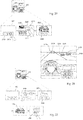
- FIG. 1A illustrates an example exterior of a vehicle including a rear combination lamp.
- FIG. 1B illustrates an example exterior of a vehicle including a rear combination lamp.
- a vehicle 700 may include wheels 103FR, 103FL, 103RR rotated by a power source, a driver assistance system 100 provided in the vehicle 700, and a rear combination lamp 200.
- the driver assistance system 100 may be provided with at least one camera, and images acquired by the at least one camera may be signal-processed in a processor 170 (see FIGS. 7A to 7C ).
- the driver assistance system 100 is provided with two cameras.
- the rear combination lamp includes various lamps attached to the back of the vehicle 700.
- the rear combination lamp may include at least one of a stop lamp, a taillight, a turn signal lamp, a fog light, a sidelight and a reverse light.
- the overall length refers to the length of the vehicle 700 from the front to back of the vehicle
- the width refers to width of the vehicle 700
- the height refers to the distance from the bottom of a wheel to the roof of the vehicle.
- the overall-length direction L may indicate a direction in which measurement of overall length of the vehicle 700 is performed
- the width direction W may indicate a direction in which measurement of width of the vehicle 700 is performed
- the height direction H may indicate a direction in which measurement of height of the vehicle 700 is performed.
- FIG. 2 is a diagram illustrating an example rear combination lamp, taken along line A-A in FIG. 1B .
- the rear combination lamp may include a display 250.
- the display 250 may include a plurality of light emitting devices.
- the display 250 may display various images in respective areas according to the control operation of a processor 270 (see FIG. 3 ).
- the display 250 may be divided into a plurality of areas, such that images corresponding to a stop lamp, a taillight, a turn signal lamp, a fog light, a sidelight and a reverse light are displayed in the respective areas.
- a lens 320 may be formed at the rear end of the display 250.
- the lens 320 may cause light generated in the display 250 to be refracted or transmitted therethrough.
- An amplification unit (e.g., a light amplifier) for amplifying the light generated in the display 250 may be further provided.
- FIG. 3 is a diagram illustrating an example rear combination lamp.
- the rear combination lamp 200 for vehicles may include a communication unit 205, an input unit 210, a memory 230, a display 250, a processor 270, an interface unit 280, and a power supply 290.
- the communication unit 205 may include at least one communication module enabling wireless communication with an external device.
- the communication unit 205 may also include a communication module for connecting the rear combination lamp 200 to at least one network.
- the communication unit 205 may exchange data with the external device.
- the external device may be a mobile terminal 600, an external server 510, or another vehicle 520.
- the communication unit 205 is configured to receive exterior style data of the rear combination lamp from the external device.
- the exterior style data may be image data provided to enable exterior styling of the rear combination lamp.
- the input unit 210 may include an input device capable of receiving user input for controlling operation of the rear combination lamp 200.
- the input unit 210 may be disposed in the vehicle 700.
- the input unit 210 may include a touch input device or a mechanical input device.
- the input unit 210 is configured to receive user inputs for controlling various operations of the rear combination lamp 200.
- the input unit 210 is configured to receive a user input for generating exterior style data of the rear combination lamp.
- the exterior style data may be image data provided to allow implementation of exterior styling of the rear combination lamp.
- the memory 230 may store basic data for each unit of the rear combination lamp 200, control data for controlling operation of each unit, and data input to and output from the rear combination lamp 200.
- the memory 230 may include various storage devices such as a ROM, RAM, EPROM, flash drive, and hard drive.
- the memory 230 may store various kinds of data for overall operation of the rear combination lamp 200 including a program for processing or controlling operation of the processor 270.
- the memory 230 may include at least one exterior style datum.
- the exterior style data may be image data provided to allow implementation of exterior styling of the rear combination lamp.
- the processor 270 is configured to control the display 250 based on the exterior style data stored in the memory 230, thereby performing exterior styling of the rear combination lamp.
- the memory 230 may store exterior style data applied as the default.
- the memory 230 may store exterior style data applied as the default when the vehicle 700 is released from the factory.
- the memory 230 may store a plurality of exterior style data. One of the exterior style data stored in the memory 230 may be selected and applied according to user input.
- the processor 270 may perform a control operation such that the exterior style datum selected from among the plurality of exterior style data stored in the memory 230 is displayed on the display 250.
- the display 250 may be disposed on the rear side of the vehicle 700.
- the display 250 may include a plurality of light emitting devices.
- the display 250 may include one of a liquid crystal display (LCD), a plasma display panel (PDP), an electroluminescence display (ELD), an organic light-emitting diode (OLED), a light-emitting diode (LED), a field emission display (FED), a vacuum fluorescent display (VFD) and an electrophoretic display (EPD).
- LCD liquid crystal display
- PDP plasma display panel
- ELD electroluminescence display
- OLED organic light-emitting diode
- LED light-emitting diode
- FED field emission display
- VFD vacuum fluorescent display
- EPD electrophoretic display
- the display 250 may be an OLED display.
- the display 250 may operate based on a control signal received from the processor 270.
- Predetermined content may be displayed in one area of the display 250.
- the content may be configuration of the rear combination lamp.
- the display 250 may be divided into a plurality of areas.
- An image corresponding to a stop lamp, taillight, turn signal lamp, fog light, sidelight or reverse light may be formed in at least one divided area of the display 250.
- the function of the stop lamp, taillight, turn signal lamp, fog light, sidelight or reverse light may be performed by emission of light from light emitting devices corresponding to the respective areas.
- the display 250 may be a transparent display.
- the display 250 may form a rear window glass 705 of the vehicle 700.
- the display 250 may include a first display unit and a second display unit.
- the first display unit may be adapted to face outward of the vehicle 700.
- the second display unit may be adapted to face inward of the vehicle 700.
- the first display unit may display an image for implementing exterior styling of the rear combination lamp.
- the second display unit may display content to be provided to the user.
- the display 250 is controlled by the processor 270.
- the processor 270 is configured to control overall operation of each unit in the rear combination lamp 200.
- the processor 270 may implement exterior styling of the rear combination lamp using light generated by the plurality of light emitting devices included in the display 250.
- the processor 270 is configured to control the display 250 to enable exterior styling.
- the processor 270 may receive condition related to driving of the vehicle.
- the condition may include at least one of forward objects information, rearward objects information, navigation information, road information, vehicle condition information, vehicle driving information, in-vehicle situation information and driving environment information.
- the processor 270 may determine at least one condition related to driving of the vehicle on which the display is disposed.
- the processor 270 may select, from among multiple exterior style images, at least one exterior style image to display based on the determined at least one condition related to driving of the vehicle.
- the processor 270 may control the display to display the at least one exterior style image selected.
- the processor 270 is configured to control the display 250 such that the image of the rear combination lamp is displayed on the display 250.
- the processor 270 may divide the display 250 into a plurality of areas.
- the processor 270 may perform a control operation such that a plurality of an image corresponding to a stop lamp, taillight, turn signal lamp, fog light, sidelight or reverse light is displayed in the plurality of divided areas of the display 250.
- the processor 270 may perform a control operation such that the rear combination lamp image displayed on the display 250 performs the function of the rear combination lamp.
- an image corresponding to the stop lamp in the rear combination lamp image may be controlled to be displayed and to function as the stop lamp.
- the processor 270 is configured to control an image corresponding to the taillight in the rear combination lamp image to be displayed and to function as the taillight.
- the processor 270 when a turn signal is received, the processor 270 is configured to control an image corresponding to the turn signal lamp in the rear combination lamp image to be displayed in a flickering manner and function as the turn signal lamp.
- the processor 270 is configured to control an image corresponding to the fog light in the rear combination lamp image to be displayed and function as the fog light.
- the fog information may be detected by the driver assistance system 100.
- the fog information may be received through a communication unit 710 of the vehicle.
- the processor 270 is configured to control an image corresponding to the sidelight in the rear combination lamp image to be displayed and function as the sidelight.
- the processor 270 is configured to control an image corresponding to the reverse light in the rear combination lamp image and function as the reverse light.
- the processor 270 may set the maximum and minimum values of the intensity of light output from the display 250.
- the processor 270 is configured to control a plurality of light emitting devices included in the display 250 such that light whose intensity is between the maximum and minimum values is output.
- the processor 270 may adjust the intensity of light output from the display 250 according to the driving situation or driving environment.
- the processor 270 is configured to receive information about the driving situation or driving environment through the interface unit 280.
- the processor 270 is configured to control the display 250 such that the intensity of light output from the display 250 in the daytime is higher than the intensity of light output from the display 250 at night. For example, determining whether it is daytime or night may be based on illuminance information sensed through an illuminance sensor.
- the processor 270 is configured to control the display 250 such that intensity of light output from the display in accordance with the weather information is adjusted.
- the processor 270 is configured to receive the weather information through the interface unit 280.
- the weather information may be detected by the driver assistance system 100. Alternatively, the weather information may be received through the communication unit 710 of the vehicle.
- the processor 270 may adjust the intensity of output light of the display 250 according to the illuminance information received through the interface unit 280.
- the processor 270 is configured to receive distance-from-following vehicle information through the interface unit 280.
- the distance-from-following vehicle information may be detected by the driver assistance system 100.
- the processor 270 may adjust the intensity of light generated by the plurality of light emitting devices included in the display 250, based on the distance-from-following vehicle information. For example, the processor 270 may adjust the intensity of light in proportion to a distance between the vehicle 700 and a following vehicle. For example, the processor 270 may cause the intensity of light to decrease as the distance between the vehicle 700 and the following vehicle decreases. For example, the processor 270 may cause the intensity of light to increase as the distance between the vehicle 700 and the following vehicle increases.
- the processor 270 is configured to control the pattern of generated light by turning on/off the plurality of light emitting devices included in the display 250 based on the distance-from-following vehicle information. For example, the processor 270 is configured to control the number of light emitting devices which are turned on such that the number increases in proportion to the distance between the vehicle 700 and the following vehicle. For example, the processor 270 is configured to control the number of light emitting devices which are turned off such that the number increase in proportion to the distance between the vehicle 700 and the following vehicle.
- the processor 270 is configured to control the display 250 to implement exterior styling based on the exterior style data stored in the memory 230.
- the processor 270 is configured to control the display 250 such that exterior styling is performed based on the user's facial expression sensed through an internal camera 195c (see FIG. 4 ). For example, if a smiling expression of the user is sensed through the internal camera 195c (see FIG. 4 ), the user facial expression information may be delivered to the processor 270 through the interface unit 280.
- the processor 270 is configured to control the display 250 such that exterior styling corresponding to the smiling expression information is performed.
- the processor 270 determine the at least one condition related to driving of the vehicle by determining the sensed user facial expression information.
- the processor 270 select, from among multiple exterior style images, the at least one exterior style image to display by selecting, from among multiple exterior style images, at least one exterior style image to display based on the sensed user facial expression information.
- the processor 270 is configured to receive exterior style data through the interface unit 280.
- the exterior style data may be image data provided such that exterior styling of the rear combination lamp is performed.
- the processor 270 is configured to control the display 250 such that exterior styling is performed based on the received exterior style data.
- the exterior style data received through the interface unit 280 may be data received from an external device 600, 510 or 520 by payment of a fee for use of the exterior style data or for free.
- the external device may be a mobile terminal 600, an external server 510 or another vehicle 520.
- the exterior style data received through the interface unit 280 may be data generated according to a user input.
- the user input may be received through a user input unit 720 or display apparatus 400 of the vehicle.
- the exterior style data received through the interface unit 280 may be data generated from an image of another vehicle acquired from a camera 195.
- the camera 195 may include a mono camera, stereo cameras 195a and 195b, or around view cameras 195d, 195e, 195f and 195g included in the driver assistance system 100.
- the camera 195 may acquire a vehicle front view image or a vehicle surroundings image.
- the camera 195 is configured to detect another vehicle in the vehicle front view image or a vehicle surroundings image.
- the processor 270 is configured to receive location information about a road on which the vehicle is traveling, through the interface unit 280.
- the processor 270 is configured to control the display 250 such that exterior styling is performed in consideration of traffic laws applied to the road.
- the processor 270 may determine the at least one condition related to driving of the vehicle by determining traffic laws applied to the road.
- the processor 270 may select, from among multiple exterior style images, the at least one exterior style image to display by selecting, from among multiple exterior style images, at least one exterior style image to display based on the traffic laws applied to the road.
- the processor 270 is configured to control the display 250 such that an image corresponding to a stop lamp, taillight, turn signal lamp, fog light, sidelight or reverse light is formed in at least one area of the display 250.
- the processor 270 is configured to control the display 250 to implement exterior styling such that the size, disposition, light intensity or color of each area for displaying an image of the stop lamp, taillight, turn signal lamp, fog light, sidelight or reverse light complies with the traffic laws.
- the processor 270 is configured to control the display 250 such that images corresponding to the stop lamp, taillight, turn signal lamp, fog light, sidelight or reverse light are displayed in at least one area of the display 250.
- the images corresponding to the stop lamp may include an image corresponding to a center high mounted stop lamp (CHMSL).
- the processor 270 may display the image of the rear combination lamp for exterior styling on the first display unit of the display 250.
- the processor 270 is configured to control the second display unit of the display 250 to display predetermined content for a user positioned inside the vehicle 700.
- the processor 270 is configured to receive, through the interface unit 280, forward objects information, rearward objects information, navigation information, road information, vehicle condition information, vehicle driving information, in-vehicle situation information or driving environment information.
- the processor 270 is configured to control the display 250 to display the received forward objects information, rearward objects information, navigation information, road information, vehicle condition information, vehicle driving information, in-vehicle situation information or driving environment information.
- the forward objects information may include traffic sign recognition (TSR) information and speed bump detection information.
- TSR traffic sign recognition
- speed bump detection information may include speed bump detection information.
- the processor 270 is configured to control the display 250 to display TSR information and speed bump detection information.
- the TSR information may include detection information on a design or text indicated on a traffic signboard, detection information on a signal output from a traffic light, and detection information on a design or text indicated on a road surface.
- the processor 270 is configured to control the display 250 to display information corresponding to a design or text indicated on a traffic signboard, a signal output from a traffic light, or a design or text indicated on a road surface.
- the processor 270 is configured to control the display 250 to display a bump image corresponding to the speed bump detection information.
- the forward objects information may include another-vehicle detection information, two-wheeled vehicle detection information, pedestrian detection information, traffic accident information, construction information or road congestion information.
- another vehicle, a two-wheeled vehicle, a pedestrian, a traffic accident situation, construction or a road congestion situation may be called an obstacle.
- the processor 270 is configured to control the display 250 to display the another-vehicle detection information, two-wheeled vehicle detection information, pedestrian detection information, traffic accident information, construction information, or road congestion information.
- the rearward objects information may be information about another vehicle traveling behind the vehicle 700.
- the navigation information may include driving route information, predetermined destination information, remaining distance information, driving area information, driving road information, and speed camera information.
- the processor 270 is configured to control the display 250 to display the driving route information, predetermined destination information, remaining distance information, driving area information, driving road information or speed camera information.
- the processor 270 may display driving route information through turn-by-turn (TBT) navigation.
- the processor 270 is configured to control the display 250 to display the driving route information with a straight arrow, a left turn arrow, a right turn arrow or a U-turn arrow.
- the road information may include information about the inclination or curvature of the road on which the vehicle is traveling.
- the processor 270 is configured to control the display 250 to display the inclination or curvature information.
- the vehicle condition information may be On Board Diagnostics (OBD) information.
- OBD On Board Diagnostics
- the vehicle condition information may include parking brake state information, high beam on/off information, washer liquid level information, engine oil level information, power source temperature information, remaining energy information, tire pressure information, brake oil level information or door opening information.
- the processor 270 is configured to control the display 250 to display the OBD information.
- the processor 270 is configured to control the display 250 to display the parking brake state information, high beam on/ off information, washer liquid level information, engine oil level information, power source temperature information, remaining energy information, tire pressure information, brake oil level information, or door opening information.
- the vehicle driving information may include driving speed information, gear shift information or turn signal information delivered to the turn signal lamp.
- the processor 270 is configured to control the display 250 to display the driving speed information, gear shift information or turn signal information.
- the processor 270 is configured to receive, through the interface unit 280, a user input that is input through the input unit 720 of the vehicle 700. In some implementations, the processor 270 is configured to control the display 250 to display information corresponding to the user input.
- the in-vehicle situation information may be patient evacuation situation information, emergency aid request information, infant-on-board information or inexperienced driver information.
- the in-vehicle situation information may be generated through the input unit 720 of the vehicle 700 according to user input.
- the driving environment information may include weather information or time information.
- the processor 270 is configured to control the display 250 to display the weather information or time information.
- the processor 270 may be controlled by the controller 770.
- the processor 270 may be implemented as hardware using at least one of application specific integrated circuits (ASICs), digital signal processors (DSPs), digital signal processing devices (DSPDs), programmable logic devices (PLDs), field programmable gate arrays (FPGAs), processors, controllers, micro-controllers, microprocessors, and electric units for performing other functions.
- ASICs application specific integrated circuits
- DSPs digital signal processors
- DSPDs digital signal processing devices
- PLDs programmable logic devices
- FPGAs field programmable gate arrays
- processors controllers, micro-controllers, microprocessors, and electric units for performing other functions.
- the interface unit 280 may exchange date with the controller 770, sensing unit 760 or driver assistance system 100 of the vehicle 700.
- the interface unit 280 is configured to receive vehicle-related data or user inputs or transmit, to the outside, a signal processed or generated by the processor 270. To this end, the interface unit 280 may perform data communication with the controller 770, the sensing unit 760, or the driver assistance system 100 provided in the vehicle in a wired or wireless manner.
- the interface unit 280 is configured to receive sensor information from the controller 770 or the sensing unit 760.
- the sensor information may include at least one of vehicle direction information, vehicle location information (GPS information), vehicle orientation information, vehicle speed information, vehicle acceleration information, vehicle inclination information, vehicle drive/reverse information, battery information, fuel information, tire information, vehicular lamp information, interior temperature information, interior humidity information, and exterior illuminance information.
- GPS information vehicle location information
- vehicle orientation information vehicle speed information
- vehicle acceleration information vehicle acceleration information
- vehicle inclination information vehicle drive/reverse information
- battery information fuel information
- tire information tire information
- vehicular lamp information interior temperature information
- interior humidity information interior humidity information
- exterior illuminance information exterior illuminance information
- Such sensor information may be acquired from a heading sensor, a yaw sensor, a gyro sensor, a position module, a vehicle drive/reverse sensor, a wheel sensor, a vehicle speed sensor, a vehicle body tilt sensor, a battery sensor, a fuel sensor, a tire sensor, a steering sensor based on turning of the steering wheel, an interior temperature sensor, an interior humidity sensor, and an illuminance sensor.
- the position module may include a GPS module for receiving GPS information.
- the vehicle direction information, vehicle location information, vehicle orientation information, vehicle speed information and vehicle inclination information which are related to traveling of the vehicle, may be called vehicle travel information.
- the interface unit 280 is configured to receive user facial expression information acquired by the internal camera 195c (see FIG. 4 ).
- the interface unit 280 is configured to receive user's emotion information.
- the emotion information may be generated based on the information input through the input unit 720 of the vehicle 700.
- the emotion information may be generated by analyzing the user's facial expression or voice input through the internal camera 195c or a microphone 723.
- the interface unit 280 is configured to receive, from the controller 770 or the driver assistance system 100, object information detected by the driver assistance system 100.
- the driver assistance system 100 may perform lane detection (LD), vehicle detection (VD), pedestrian detection (PD), bright spot detection (BD), traffic sign recognition (TSR), and road surface detection, based on an acquired front view image of the vehicle 700.
- the driver assistance system 100 may generate information about a distance to a detected object.
- the interface unit 280 is configured to receive the detected object information from the driver assistance system 100. Alternatively, the interface unit 280 is configured to receive the detected object information via the controller 770.
- the interface unit 280 is configured to receive forward objects information, rearward objects information, navigation information, road information, vehicle condition information, vehicle driving information, in-vehicle situation information or driving environment information.
- the interface unit 280 is configured to receive information about a distance to an object in front of or behind the vehicle.
- the interface unit 280 is configured to receive a user input that is input through the input unit 720 of the vehicle 700.
- the interface unit 280 is configured to receive exterior style data.
- the exterior style data may be image data provided to enable implementation of exterior styling of the rear combination lamp.
- the exterior style data may be received from an external device 600, 510 or 520 (see FIG. 4 ) by payment or for free.
- the external device may be a mobile terminal 600, a server 510, or another vehicle 520.
- exterior style data may be generated by user input.
- the exterior style data may be generated from an image of another vehicle detected by the camera 195 for photographing the outside of the vehicle 700.
- the interface unit 280 is configured to receive navigation information through data communication with the controller 770, the display apparatus 400 or a separate navigation device.
- the navigation information may include predetermined destination information, route information according to the destination, map information, and current location information, wherein the map information and the current location information are related to traveling of the vehicle.
- the navigation information may include information about the location of the vehicle on the road.
- the driver assistance system 100 will be described in more detail with reference to FIGS. 5 to 7C .
- the power supply 290 may be controlled by the processor 270 to supply electric power necessary for operation of each unit of the rear combination lamp 200.
- the power supply 290 is configured to receive power from, for example, a battery in the vehicle 700.
- FIG. 4 is a diagram illustrating an example vehicle.
- the vehicle 700 may include a communication unit 710, an input unit 720, a sensing unit 760, an output unit 740, a vehicle drive unit 750, a memory 730, an interface unit 780, a controller 770, a power supply 790, a driver assistance system 100, a rear combination lamp 200 and a display apparatus 400.
- the communication unit 710 may include at least one module enabling wireless communication between the vehicle 700 and the mobile terminal 600, between the vehicle 700 and the external server 510 or between the vehicle 700 and another vehicle 520.
- the communication unit 710 may also include at least one module for connecting the vehicle 700 to at least one network.
- the communication unit 710 is configured to receive exterior style data from an external device 600, 510 or 520 by communicating with the external device.
- the communication unit 710 may provide the received exterior style data to the rear combination lamp 200.
- the communication unit 710 is configured to receive the exterior style data from the external device 600, 510 or 520 by payment or for free.
- the communication unit 710 may exchange payment information with the external devices 600, 510 and 520.
- the communication unit 710 is configured to receive the exterior style data through a short-range communication module 713.
- the communication unit 710 is configured to receive the exterior style data through a wireless Internet module 712.
- the communication unit 710 is configured to receive traffic accident information, construction information or road congestion information from the external devices 600, 510 and 520.
- the communication unit 710 is configured to receive traffic accident information, construction information or road congestion information through the wireless Internet module 712.
- the communication unit 710 may include a broadcast reception module 711, the wireless Internet module 712, the short-range communication module 713, the location information module 714 and an optical communication module 715.
- the broadcast reception module 711 receives a broadcast signal or broadcast-related information from an external broadcast management server over a broadcast channel.
- the broadcast includes radio broadcast or TV broadcast.
- the wireless Internet module 712 which refers to a module for wireless Internet access, may be internally or externally installed on the vehicle 700.
- the wireless Internet module 712 is configured to transmit and receive a radio signal on a communication network according to wireless Internet technologies.
- wireless Internet technologies include Wireless LAN (WLAN), Wi-Fi, Wi-Fi Direct, Digital Living Network Alliance (DLNA), Wireless Broadband (WiBro), World Interoperability for Microwave Access (WiMAX), High Speed Downlink Packet Access (HSDPA), High Speed Uplink Packet Access (HSUPA), Long Term Evolution (LTE), and Long Term Evolution-Advanced (LTE-A).
- the wireless Internet module 712 transmits and receives data according to at least one wireless Internet technology selected from among wireless Internet technologies including the aforementioned technologies.
- the wireless Internet module 712 may wirelessly exchange data with the external server 510.
- the wireless Internet module 712 is configured to receive weather information and traffic situation information (e.g., TPEG (Transport Protocol Expert Group)) from the external server 510.
- TPEG Transport Protocol Expert Group
- the short-range communication module 713 which is intended for short-range communication, may support short-range communication using at least one of BluetoothTM, Radio Frequency Identification (RFID), Infrared Data Association (IrDA), Ultra Wideband (UWB), ZigBee, Near Field Communication (NFC), Wi-Fi, Wi-Fi Direct, and Wireless Universal Serial Bus (Wireless USB) technologies.
- RFID Radio Frequency Identification
- IrDA Infrared Data Association
- UWB Ultra Wideband
- ZigBee Near Field Communication
- Wi-Fi Wi-Fi Direct
- Wireless Universal Serial Bus Wireless Universal Serial Bus
- the short-range communication module 713 may establish a wireless local area network to implement short-range communication between the vehicle 700 and at least one external device.
- the short-range communication module 713 may wirelessly exchange data with the mobile terminal 600.
- the short-range communication module 713 is configured to receive weather information, and traffic situation information (e.g., TPEG (Transport Protocol Expert Group)) from the mobile terminal 600.
- traffic situation information e.g., TPEG (Transport Protocol Expert Group)
- a typical example of the location information module 714 which serves to acquire the location of the vehicle 700, is a global positioning system (GPS) module.
- GPS global positioning system
- the location of the vehicle may be acquired using a signal from a GPS satellite.
- the optical communication module 715 may include a light transmitter and a light receiver.
- the light receiver may covert a light signal to an electrical signal to receiver information.
- the light receiver may include a photodiode (PD) for receiving light.
- the PD is capable of converting light into an electrical signal.
- the light receiver is configured to receive information on a foregoing vehicle through light emitted from a light source included in the foregoing vehicle.
- the light transmitter may include at least one light emitting device for converting an electrical signal to a light signal.
- the light emitting device is a light emitting diode (LED).
- the light transmitter coverts an electrical signal into a light signal and transmits the light signal outside.
- the light transmitter transmits a light signal by blinking a light emitting device at a predetermined frequency.
- the light transmitter may include an array of a plurality of light emitting devices.
- the light transmitter may be integrated with a lamp provided to the vehicle 700.
- the light transmitter may be at least one of a headlight, a taillight, a stop lamp, a turn signal lamp and a sidelight.
- the optical communication module 715 may exchange data with another vehicle 520 through optical communication.
- the input unit 720 may include a driving manipulation device 721, a camera 195, a microphone 723 and a user input unit 724.
- the driving manipulation device 721 receives user input for driving the vehicle 700.
- the driving manipulation device 721 may include a steering input device 721a, a shift input device 721b, an acceleration input device 721c, and a brake input device 721d.
- the steering input device 721a receives a travel direction input of the vehicle 700 from the user.
- the steering input device 721a is preferably formed in the shape of a wheel such that steering can be input by a turning operation.
- the steering input device 721a may be defined in the form of a touchscreen, touch pad, or button.
- the shift input device 721b receives, from the user, inputs of Park (P), Drive (D), Neutral (N) and Reverse (R) of the vehicle 700.
- the shift input device 721b is formed in the shape of a lever.
- the shift input device 721b may be defined in the form of a touchscreen, touch pad, or button.
- the acceleration input device 721c receives an input for accelerating the vehicle 700 from the user.
- the brake input device 721d receives an input for decelerating the vehicle 700 from the user.
- the acceleration input device 721c and the brake input device 721d are formed in the shape of a pedal.
- the acceleration input device 721c or the brake input device 721d may be defined in the form of a touchscreen, touch pad, or button.
- the camera 195 may include an image sensor and an image processing module.
- the camera 195 may process a still image or a moving image obtained by the image sensor (e.g., CMOS or CCD).
- the image processing module may process the still image or moving image acquired through the image sensor to extract necessary information and deliver the extracted information to the controller 770.
- the vehicle 700 may include a camera 195 for capturing an image of a front view or surroundings of the vehicle and an internal camera 195c for capturing an image of the inside of the vehicle.
- the internal camera 195c may acquire an image of a person on board.
- the internal camera 195c may obtain an image for biometric identification of the person.
- FIG. 4 illustrates the camera 195 as being included in the input unit 720, the camera 195 may be included in the driver assistance system 100.
- the microphone 723 may process an external sound signal to create electrical data.
- the data created through the processing may be utilized for various purposes according to a function in execution in the vehicle 700.
- the microphone 723 may convert a voice command from the user into electrical data.
- the electrical data may be delivered to the controller 770.
- the camera 722 or the microphone 723 may be included in the sensing unit 760 rather than in the input unit 720.
- the user input unit 724 is intended to receive information input by the user.
- the controller 770 is configured to control operation of the vehicle 700 in accordance with the input information.
- the user input unit 724 may include a touch input device or a mechanical input device.
- the user input unit 724 may be disposed in one area of the steering wheel.
- the driver may manipulate the user input unit 724 with fingers while holding the steering wheel.
- the sensing unit 760 senses a signal related to traveling of the vehicle 700.
- the sensing unit 760 may include a collision sensor, a wheel sensor, a speed sensor, a tilt sensor, a weight sensor, a heading sensor, a yaw sensor, a gyro sensor, a position module, a vehicle drive/reverse sensor, a battery sensor, a fuel sensor, a tire sensor, a steering sensor based on turning of the steering wheel, an interior temperature sensor, an interior humidity sensor, an ultrasonic sensor, radar, lidar, and an illuminance sensor.
- the sensing unit 760 may acquire vehicle collision information, vehicle direction information, vehicle location information (GPS information), vehicle orientation information, vehicle speed information, vehicle acceleration information, vehicle inclination information, vehicle drive/reverse information, battery information, fuel information, tire information, vehicular lamp information, interior temperature information, interior humidity information, a sensing signal for an angle by which the steering wheel is rotated, and illuminance information on the exterior of the vehicle.
- GPS information vehicle location information
- vehicle orientation information vehicle speed information
- vehicle acceleration information vehicle acceleration information
- vehicle inclination information vehicle drive/reverse information
- battery information fuel information
- tire information tire information
- vehicular lamp information interior temperature information
- interior humidity information interior humidity information
- a sensing signal for an angle by which the steering wheel is rotated illuminance information on the exterior of the vehicle.
- the sensing unit 760 may further include an accelerator pedal sensor, a pressure sensor, an engine speed sensor, an air flow sensor (AFS), an intake air temperature sensor (ATS), a water temperature sensor (WTS), a throttle position sensor (TPS), a TDC sensor, and a crankshaft angle sensor (CAS).
- AFS air flow sensor
- ATS intake air temperature sensor
- WTS water temperature sensor
- TPS throttle position sensor
- TDC TDC sensor
- CAS crankshaft angle sensor
- the sensing unit 760 may include a biometric identification information sensing unit.
- the biometric identification information sensing unit senses and acquires biometric identification information of a passenger.
- the biometric identification information may include fingerprint information, iris-scan information, retina-scan information, hand geometry information, facial recognition information, and voice recognition information.
- the biometric identification information sensing unit may include a sensor for sensing biometric identification information of a passenger.
- the internal camera 195c and the microphone 723 may operate as sensors.
- the biometric identification information sensing unit may acquire hand geometry information and facial recognition information through the internal camera 195c.
- the output unit 740 which serves to output information processed by the controller 770, may include a display unit 741, a sound output unit 742 and a haptic output unit 743.
- the display unit 741 may display information processed by the controller 770.
- the display unit 741 may display vehicle-related information.
- the vehicle-related information may include vehicle control information for direction control of the vehicle or vehicle driving assistance information for assisting the driver in driving.
- the vehicle-related information may also include vehicle condition information indicating the current condition of the vehicle or vehicle driving information related to driving of the vehicle.
- the display unit 741 may include at least one of a liquid crystal display (LCD), a thin film transistor-liquid crystal display (TFT LCD), an organic light-emitting diode (OLED), a flexible display, a 3D display, and an e-ink display.
- LCD liquid crystal display
- TFT LCD thin film transistor-liquid crystal display
- OLED organic light-emitting diode
- the display unit 741 may form a layered architecture together with a touch sensor or be integrated with the touch sensor, thereby implementing a touchscreen.
- Such touchscreen may function as the user input unit 724 providing an input interface between the vehicle 700 and the user and also as an output interface between the vehicle 700 and the user.
- the display unit 741 may include a touch sensor for sensing a touch applied to the display unit 741 in order to receive a control command in a touch manner. Thereby, when the display unit 741 is touched, the touch sensor may sense the touch, and the controller 770 may generate a control command corresponding to the touch.
- Content input through touch may include characters, numbers, or menu items which can be indicated or designated in various modes.
- the display unit 741 may include a cluster to allow a driver to check the vehicle condition information or vehicle driving information while driving the engine.
- the cluster may be positioned on the dashboard.
- the driver can check the information displayed on the cluster while looking forward of the vehicle.
- the display unit 741 may be implemented as a head up display (HUD). If the display unit 741 is implemented as the HUD, information may be output through a transparent display provided to the windshield. Alternatively, the display unit 741 may be provided with a projection module, thereby, outputting information through an image projected on the windshield.
- HUD head up display
- a display unit 141 may be integrated with the display apparatus 400, which will be described later.
- the sound output unit 742 converts an electrical signal from the controller 770 into an audio signal and outputs the audio signal. To this end, the sound output unit 742 may be provided with a speaker. The sound output unit 742 may output a sound corresponding to an operation of the user input unit 724.
- the haptic output unit 743 generates a haptic output.
- the haptic output unit 743 may vibrate the steering wheel, a seat belt and a seat to allow the user to recognize the output.
- the vehicle drive unit 750 is configured to control operation of various vehicular devices.
- the vehicle drive unit 750 may include a power source drive unit 751, a steering drive unit 752, a brake drive unit 753, a lamp drive unit 754, an air conditioning drive unit 755, a window drive unit 756, an airbag drive unit 757, a sunroof drive unit 758 and a suspension drive unit 759.
- the power source drive unit 751 may perform electronic control of the power source in the vehicle 700.
- the power source drive unit 751 may perform electric control on the engine. Thereby, the output torque of the engine may be controlled. If the power source drive unit 751 is an engine, the output torque of the engine may be controlled by the controller 770 to limit the speed of the vehicle.
- the power source drive unit 751 may perform control operation on the motor. Thereby, the rotational speed and torque of the motor may be controlled.
- the steering drive unit 752 may perform electronic control of the steering apparatus in the vehicle 700. Thereby, the travel direction of the vehicle may be changed.
- the brake drive unit 753 may perform electronic control of a brake apparatus in the vehicle 700. For example, by controlling the operation of the brakes disposed on the wheels, the speed of the vehicle 700 may be reduced. In another example, the brake disposed on a left wheel may be operated differently from the brake disposed on a right wheel in order to adjust the travel direction of the vehicle 700 to the left or right.
- the air conditioning drive unit 755 may perform electronic control of an air conditioner in the vehicle 700. For example, if the temperature of the inside of the vehicle is high, the air conditioning drive unit 755 is configured to control the air conditioner to supply cool air to the inside of the vehicle.
- the window drive unit 756 may perform electronic control of a window apparatus in the vehicle 700.
- the unit is configured to control opening or closing of the left and right windows on both sides of the vehicle.
- the airbag drive unit 757 may perform electronic control of an airbag apparatus in the vehicle 700.
- the unit is configured to control the airbag apparatus such that the airbags are inflated when the vehicle is exposed to danger.
- the sunroof drive unit 758 may perform electronic control of a sunroof apparatus in the vehicle 700.
- the unit is configured to control opening or closing of the sunroof.
- the suspension drive unit 759 may perform electronic control of a suspension apparatus in the vehicle 700. For example, when a road surface is uneven, the unit is configured to control the suspension apparatus to attenuate vibration of the vehicle 700.
- the memory 730 is electrically connected to the controller 770.
- the memory 730 may store basic data for each unit, control data for controlling operation of each unit, and input/output data.
- the memory 730 may include various storage devices such as a ROM, RAM, EPROM, flash drive, and hard drive.
- the memory 730 may store various kinds of data for overall operation of the vehicle 700 including a program for processing or controlling operation of the controller 770.
- the interface unit 780 may serve as a path between the vehicle 700 and various kinds of external devices connected thereto.
- the interface unit 780 may be provided with a port connectable to the mobile terminal 600, and thus be connected to the mobile terminal 600 through the port.
- the interface unit 780 may exchange data with the mobile terminal 600.
- the interface unit 780 may also serve as a path through which electric energy is supplied to the mobile terminal 600 connected thereto. If the mobile terminal 600 is electrically connected to the interface unit 780, the interface unit 780 is controlled by the controller 770 to provide the mobile terminal 600 with electric energy supplied from the power supply 790.
- the controller 770 is configured to control overall operations of the respective units in the vehicle 700.
- the controller 770 may be called an electronic control unit (ECU).
- ECU electronice control unit
- the controller 770 may be implemented as hardware using at least one of application specific integrated circuits (ASICs), digital signal processors (DSPs), digital signal processing devices (DSPDs), programmable logic devices (PLDs), field programmable gate arrays (FPGAs), processors, controllers, micro-controllers, microprocessors, and electric units for performing other functions.
- ASICs application specific integrated circuits
- DSPs digital signal processors
- DSPDs digital signal processing devices
- PLDs programmable logic devices
- FPGAs field programmable gate arrays
- processors controllers, micro-controllers, microprocessors, and electric units for performing other functions.
- the power supply 790 may be controlled by the controller 770 to supply electric power necessary for operation of respective constituents.
- the power supply 790 is configured to receive power from, for example, a battery in the vehicle.
- the driver assistance system 100 may exchange data with the controller 770.
- a signal or data from the driver assistance system 100 may be output to the controller 770.
- a signal or data from the driver assistance system 100 may be output to the rear combination lamp 200.
- the rear combination lamp 200 may be the rear combination lamp for vehicles described above with reference to FIGS. 1 to 3 .
- the display apparatus 400 may exchange data with the controller 770.
- a signal or data from the display apparatus 400 may be output to the controller 770.
- a signal or data from the display apparatus 400 may be output to the rear combination lamp 200.
- the display apparatus 400 may be integrated with the user input unit 724 and the display unit 741 described above. In some implementations, the display apparatus 400 is configured to receive user input according to a touch gesture. In addition, the display apparatus 400 may display predetermined content.
- the display apparatus 400 may display a plurality of exterior style images.
- the display apparatus 400 is configured to receive user input of selecting one of the displayed exterior style images.
- the exterior style data include exterior style images.
- the exterior style data may be image data provided to enable implementation of exterior styling of the rear combination lamp.
- the processor 270 of the rear combination lamp 200 for vehicles is configured to control the display 250 to perform the exterior styling based on the selected exterior style image.
- the exterior style data may be data received from an external device 600, 510 or 520 by payment or for free.
- the external device may be a mobile terminal 600, an external server 510 or another vehicle 520.
- the exterior style data may be data generated according to user input.
- the user input may be received through the user input unit 720 or display apparatus 400 of the vehicle.
- the exterior style data may be data generated from an image of another vehicle acquired from the camera 195.
- the camera 195 may include a mono camera, stereo cameras 195a and 195b, or around view cameras 195d, 195e, 195f and 195g as included in the driver assistance system 100.
- the display apparatus 400 for vehicles may display at least one exterior style image generated by a user input. If the exterior style image is selected, the display apparatus 400 may provide exterior style data corresponding to the exterior style image to the rear combination lamp 200.
- the display apparatus 400 may display a plurality of exterior style images.
- the display apparatus 400 is configured to receive user input of selecting one of the displayed exterior style images.
- the processor 270 of the rear combination lamp 200 is configured to control the display 250 such that exterior styling is performed according to the selected exterior style image.
- the display apparatus 400 may display a plurality of exterior style images corresponding to the plurality of exterior style data.
- the display apparatus 400 is configured to receive user input of selecting one of the displayed exterior style images.
- the processor 270 of the rear combination lamp 200 is configured to control the display 250 such that exterior styling is performed according to the selected exterior style image.
- the display apparatus 400 may be controlled by the controller 770.
- FIG. 5 is a diagram illustrating an example camera attached to the vehicle.
- FIG. 6A is a diagram illustrating an example camera attached to the vehicle.
- FIG. 6B is a diagram illustrating an example camera attached to the vehicle.
- a driving assistance system including cameras 195a and 195b for acquiring an image of the front view of the vehicle, with reference to FIG. 5 .
- driver assistance system 100 is illustrated as including two cameras in FIG. 5 , it is apparent that the number of cameras is not limited thereto.
- the driver assistance system 100 may include a first camera 195a provided with a first lens 193a and a second camera 195b provided with a second lens 193b.
- the camera 195 may be called a stereo camera.
- the driver assistance system 100 may include a first light shield 192a and a second light shield 192b, which are intended to shield light incident on the first lens 193a and the second lens 193b, respectively.
- the driver assistance system 100 shown in the figure may be detachably attached to the ceiling or windshield of the vehicle 700.
- the driver assistance system 100 may acquire stereo images of the front view of the vehicle from the first and second cameras 195a and 195b, perform disparity detection based on the stereo images, perform object detection in at least one stereo image based on the disparity information, and continuously track movement of an object after the object detection.
- a driving assistance system including cameras 195d, 195e, 195f and 195g for acquiring images of the surroundings of the vehicle with reference to FIGS. 6A and 6B .
- FIGS. 6A and 6B illustrate the driver assistance system 100 as including four cameras, it is apparent that the number of cameras is not limited thereto.
- the driver assistance system 100 may include a plurality of cameras 195d, 195e, 195f and 195g.
- the camera 195 may be called an around view camera.
- the cameras 195d, 195e, 195f and 195g may be disposed at the left, back, right and front of the vehicle, respectively.
- the left camera 195d may be disposed in a case surrounding the left side-view mirror. Alternatively, the left camera 195d may be disposed at the exterior of the case surrounding the left side-view mirror. Alternatively, the left camera 195d may be disposed in one outer area of the left front door, left rear door or left fender.
- the right camera 195f may be disposed in a case surrounding the right side-view mirror. Alternatively, the right camera 195f may be disposed at the exterior of the case surrounding the right side-view mirror. Alternatively, the right camera 195f may be disposed at one outer area of the right front door, right rear door or right fender.
- the rear camera 195e may be disposed near the rear license plate or trunk switch.
- the front camera 195g may be disposed near the badge or radiator grille.
- Images captured by the plurality of cameras 195d, 195e, 195f and 195g may be delivered to the processor 170, and the processor 170 may synthesize the images to generate an image of the surroundings of the vehicle.
- FIG. 6B shows an exemplary image of the surroundings of the vehicle.
- a vehicle surroundings image 201 may include a first image area 195di of an image captured by the left camera 195d, a second image area 195ei of an image captured by the rear camera 195e, the third image area 195fi of an image captured by the right camera 195f, and the fourth image area of an image captured by the front camera 195g.
- boundary parts may be produced among the respective image areas.
- the boundary parts may be processed through image blending to expression natural when they are displayed.
- boundary lines 202a, 202b, 202c, and 202d may be displayed on the respective boundaries of a plurality of images.
- the vehicle surroundings image 201 may include a vehicle image 700i.
- the vehicle image 700i may be generated by the processor 170.
- the vehicle surroundings image 201 may be displayed through the display unit 741 of the vehicle or the display unit 180 of the driver assistance system.
- FIG. 7A is a diagram illustrating an example interior of a driver assistance system.
- FIG. 7B is a diagram illustrating an example interior of a driver assistance system.
- FIG. 7C is a diagram illustrating an example interior of a driver assistance system.
- the driver assistance system 100 may generate vehicle-related information by performing signal processing of an image received from the camera 195 based on computer vision.
- the vehicle-related information may include vehicle control information for direction control of the vehicle or vehicle driving assistance information for assisting the driver in driving.
- the camera 195 may be a mono camera for capturing images of the front view or rear view of the vehicle.
- the camera 195 may include stereo cameras 195a and 195b for capturing images of the front view or rear view of the vehicle.
- the camera 195 may include around view cameras 195d, 195e, 195f and 195g for capturing images of surroundings of the vehicle.
- FIG. 7A is a block diagram illustrating the interior of the driver assistance system 100.
- the driver assistance system 100 may include an input unit 110, a communication unit 120, an interface unit 130, a memory 140, a processor 170, a power supply 190, a camera 195, a display unit 180 and an audio output unit 185.
- the input unit 110 may be equipped with a plurality of buttons or a touchscreen attached to the driver assistance system 100, in particular, the internal camera 195c.
- the driver assistance system 100 may be turned on and operated through the plurality of buttons or the touchscreen.
- Various input operations may also be performed through the buttons or touchscreen.
- the communication unit 120 may wirelessly exchange data with the mobile terminal 600 or the server 500.
- the communication unit 120 may wirelessly exchange data with a mobile terminal of the vehicle driver.
- Wireless data communication schemes may include Bluetooth, Wi-Fi Direct, Wi-Fi, APiX, and NFC.
- the communication unit 120 is configured to receive weather information and traffic situation information (e.g., TPEG (Transport Protocol Expert Group)) from the mobile terminal 600 or the server 500.
- the driver assistance system 100 may transmit recognized real-time information to the mobile terminal 600 or the server 500.
- the mobile terminal 600 of the user may be paired with the driver assistance system 100 automatically or by execution of an application by the user.
- the communication unit 120 is configured to receive change-of-traffic light information from the external server 510.
- the external server 510 may be a server positioned at a traffic control center that controls traffic.
- the interface unit 130 is configured to receive vehicle-related data or transmit a signal processed or generated by the processor 170. To this end, the interface unit 130 may perform data communication with the controller 770, the display apparatus 400, the sensing unit 760 and the like which are included in the vehicle through wired or wireless communication.
- the interface unit 130 is configured to receive navigation information through data communication with the controller 770, the display apparatus 400 or a separate navigation apparatus.
- the navigation information may include predetermined destination information, route information according to the destination, map information, and current location information, wherein the map information and the current location information are related to traveling of the vehicle.
- the navigation information may include information about the location of the vehicle on the road.
- the interface unit 130 is configured to receive sensor information from the controller 770 or the sensing unit 760.
- the sensor information may include at least one of vehicle direction information, vehicle location information (GPS information), vehicle orientation information, vehicle speed information, vehicle acceleration information, vehicle inclination information, vehicle drive/reverse information, battery information, fuel information, tire information, vehicular lamp information, and interior temperature information, interior humidity information.
- GPS information vehicle location information
- vehicle orientation information vehicle speed information
- vehicle acceleration information vehicle acceleration information
- vehicle inclination information vehicle drive/reverse information
- battery information fuel information
- tire information tire information
- vehicular lamp information vehicular lamp information
- interior temperature information, interior humidity information interior humidity information.
- Such sensor information may be acquired from a heading sensor, a yaw sensor, a gyro sensor, a position module, a vehicle drive/reverse sensor, a wheel sensor, a vehicle speed sensor, a vehicle body tilt sensor, a battery sensor, a fuel sensor, a tire sensor, a steering sensor based on turning of the steering wheel, a interior temperature sensor, and a interior humidity sensor.
- the position module may include GPS module for receiving GPS information.
- the vehicle direction information, vehicle location information, vehicle orientation information, vehicle speed information and vehicle inclination information which are related to traveling of the vehicle, may be called vehicle travel information.
- the memory 140 may store various kinds of data for overall operation of the driver assistance system 100 including a program for processing or controlling operation of the processor 170.
- the memory 140 may store data for identifying an object. For example, if a predetermined object is detected in an image acquired through the camera 195, the memory 140 may store data for identifying the object according to a predetermined algorithm.
- the memory 140 may store traffic information data. For example, if predetermined traffic information is detected in an image acquired through the camera 195, the memory 140 may store data for identifying the traffic information according to a predetermined algorithm.
- the memory 140 may include various storage devices such as a ROM, RAM, EPROM, flash drive, and hard drive.
- the processor 170 is configured to control overall operation of each unit in the driver assistance system 100.
- the processor 170 may process an image of the vehicle front view image or a vehicle surroundings image acquired by the camera 195.
- the processor 170 performs signal processing based on computer vision.
- the processor 170 may acquire an image of the front view or surroundings of the vehicle from the camera 195, and is configured to detect and track an object based on the image.
- the processor 170 may perform lane detection (LD), vehicle detection (VD), pedestrian detection (PD), bright spot detection (BD), traffic sign recognition (TSR), and road surface detection.
- LD lane detection
- VD vehicle detection
- PD pedestrian detection
- BD bright spot detection
- TSR traffic sign recognition
- a traffic sign may represent predetermined information which can be delivered to the driver of the vehicle 700.
- the traffic sign may be delivered to the deriver through a traffic light, a traffic signboard or a road surface.
- the traffic sign may be a Go or Stop signal output from a traffic light for a vehicle or pedestrian.
- the traffic sign may include various designs or texts marked on traffic signboards.
- the traffic sign may include various designs or texts marked on the road surface.
- the processor 170 is configured to detect information in a vehicle front view image, vehicle rear view image or surroundings-of-vehicle image acquired by the camera 195.
- the information may include forward objects information, rearward objects information, and road information.
- the processor 170 may compare the detection information with information stored in the memory 140 to identify the information.
- the processor 170 is configured to control zoom of the camera 195.
- the processor 170 is configured to control zoom of the camera 195 according to a result of the object detection. For example, if a traffic signboard is detected, but details marked on the traffic signboard are not detected, the processor 170 is configured to control the camera 195 such that the camera 195 zooms in.
- the processor 170 is configured to receive weather information and traffic situation information (e.g., TPEG (Transport Protocol Expert Group)) through the communication unit 120.
- TPEG Transport Protocol Expert Group
- the processor 170 may recognize, in real time, information about a traffic situation around the vehicle recognized by the driver assistance system 100 based on stereo images.
- the processor 170 is configured to receive navigation information from the display apparatus 400 or a separate navigation apparatus through the interface unit 130.
- the processor 170 is configured to receive sensor information from the controller 770 or the sensing unit 760 through the interface unit 130.
- the sensor information may include at least one of vehicle direction information, vehicle location information (GPS information), vehicle orientation information, vehicle speed information, vehicle acceleration information, vehicle inclination information, vehicle drive/reverse information, battery information, fuel information, tire information, vehicular lamp information, interior temperature information, interior humidity information and steering wheel rotation information.
- the processor 170 is configured to receive navigation information from the controller 770, the display apparatus 400, or a separate navigation apparatus through the interface unit 130.
- the processor 170 is configured to detect a relative distance to an object based on change in size of the object detected in time.
- the processor 170 is configured to detect a relative speed of the detected object based on the detected relative distance and vehicle speed.
- the processor 170 is configured to detect a front object.
- the processor 170 is configured to detect a relative distance to the front object based on change in size of the front object detected in time.
- the front object may be a foregoing vehicle.
- the processor 170 is configured to detect a rear object.
- the processor 170 is configured to detect a relative distance to the rear object based on change in size of the rear object detected in time.
- the rear object may be a following vehicle.
- the processor 170 is configured to detect another vehicle in a vehicle front view image or surroundings-of-vehicle image.
- the processor 170 may generate exterior style data based on the rear combination lamp of the detected vehicle.
- the processor 170 may provide the exterior style data to the rear combination lamp 200.
- the processor 170 may provide an image of the detected vehicle to the rear combination lamp 200.
- the processor 270 of the rear combination lamp 200 may generate exterior style data based on the received image of the vehicle.
- the processor 170 may be implemented using at least one of application specific integrated circuits (ASICs), digital signal processors (DSPs), digital signal processing devices (DSPDs), programmable logic devices (PLDs), field programmable gate arrays (FPGAs), processors, controllers, micro-controllers, microprocessors, and electric units for performing other functions.
- ASICs application specific integrated circuits
- DSPs digital signal processors
- DSPDs digital signal processing devices
- PLDs programmable logic devices
- FPGAs field programmable gate arrays
- processors controllers, micro-controllers, microprocessors, and electric units for performing other functions.
- the processor 170 may be controlled by the controller 770.
- the display unit 180 may display various kinds of information processed by the processor 170.
- the display unit 180 may display an image related to operation of the driver assistance system 100.
- the display unit 180 may include a cluster or HUD on the inner front of the vehicle. If the display unit 180 is an HUD, the unit may include a projection module for projecting an image onto the wind shied of the vehicle 700.
- the audio output unit 185 may output sound based on an audio signal processed by the processor 170.
- the audio output unit 185 may include at least one speaker.
- An audio input unit is configured to receive a user's voice.
- the unit may include a microphone.
- the received voice may be converted into an electrical signal and delivered to the processor 170.
- the power supply 190 may be controlled by the processor 170 to supply electric power necessary for operation of respective constituents.
- the power supply 190 is configured to receive power from, for example, a battery in the vehicle.
- the camera 195 acquires a vehicle front view image, a vehicle rear view image or a surroundings-of-vehicle image.
- the camera 195 may be a mono camera or stereo camera 195a, 195b for capturing the vehicle front view image or rear view image.
- the camera 195 may include a plurality of cameras 195d, 195e, 195f and 195g for capturing a surroundings-of-vehicle image.
- the camera 195 may include an image sensor (e.g., CMOS or CCD) and an image processing module.
- an image sensor e.g., CMOS or CCD
- an image processing module e.g., CMOS or CCD
- the camera 195 may process a still image or a moving image obtained by the image sensor.
- the image processing module may process the still image or moving image acquired through the image sensor.
- the image processing module may be configured separately from the processor 170 or integrated with the processor 170.
- Zoom of the camera 195 may be controlled by the processor 170.
- a zoom barrel included in the camera 195 may be moved as controlled by the processor 170, thereby setting the zoom.
- the camera 195 may be controlled by the processor 170 to set the focus.
- a focus barrel included in the camera 195 may be moved as controlled by the processor 170, thereby setting the focus.
- the focus may be automatically set based on the zoom setting.
- the processor 170 may automatically control the focus according to zoom control of the camera 195.
- the camera 195 is configured to detect a front object or rear object of the vehicle.
- FIG. 7B is a block diagram illustrating the interior of the driver assistance system 100.
- the driver assistance system 100 of FIG. 7B differs from the driver assistance system 100 of FIG. 7A in that the system of FIG. 7B includes stereo cameras 195a and 195b.
- the system of FIG. 7B includes stereo cameras 195a and 195b.
- the driver assistance system 100 may include first and second cameras 195a and 195b.
- the first and second cameras 195a and 195b may be called stereo cameras.
- the stereo camera 195a and 195b may be detachably formed on the ceiling or windshield of the vehicle 700.
- the stereo camera 195a and 195b may include a first lens 193a and a second lens 193b.
- the stereo camera 195a and 195b may include a first light shield 192a and a second light shield 192b, which are intended to shield light incident on the first lens 193a and the second lens 193b, respectively.
- the first camera 195a acquires a first image of the front view of the vehicle.
- the second camera 195b acquires a second image of the front view of the vehicle.
- the second camera 195b is spaced a predetermined distance from the first camera 195a.
- a disparity therebetween is produced, and a distance to an object may be detected according to the disparity.
- the processor 170 performs signal processing based on computer vision. Thereby, the processor 170 may acquire stereo images of the front view of the vehicle from the stereo cameras 195a and 195b, perform disparity calculation based on the stereo images, perform object detection in at least one of the stereo images based on the calculated disparity information, and continuously track movement of an object after object detection. For example, the stereo images are based on the first image received from the first camera 195a and the second image received from the second camera 195b.
- the processor 170 may perform lane detection (LD), vehicle detection (VD), pedestrian detection (PD), bright spot detection (BD), traffic sign recognition (TSR), and road surface detection.
- LD lane detection
- VD vehicle detection
- PD pedestrian detection
- BD bright spot detection
- TSR traffic sign recognition
- the processor 170 may calculate the distance to a detected vehicle, the speed of the detected vehicle, and difference in speed from the detected vehicle.
- the processor 170 is configured to control zoom of the first and second cameras 195a and 195b individually.
- the processor 170 may periodically change the zoom ratio of the second camera 195b, keeping the zoom ratio of the first camera 195a constant.
- the processor 170 may periodically change the zoom ratio of the first camera 195a, keeping the zoom ratio of the second camera 195b constant.
- the processor 170 is configured to control the first or second camera 195a or 195b to zoom in or out with a predetermined periodicity.
- the processor 170 may set a high zoom ratio of the first camera 195a to readily detect a distant object.
- the processor 170 may also set a low zoom ratio of the second camera 195b to readily detect a nearby object.
- the processor 170 is configured to control the first camera 195a and the second camera 195b such that the first camera 195a zooms in and the second camera 195b zooms out.
- the processor 170 may set a low zoom ratio of the first camera 195a to readily detect a nearby object.
- the processor 170 may also set a high zoom ratio of the second camera 195b to readily detect a distant object.
- the processor 170 is configured to control the first camera 195a and the second camera 195b such that the first camera 195a zooms out and the second camera 195b zooms in.
- the processor 170 is configured to control zoom of the first camera 195a or the second camera 195b according to a result of the object detection. For example, if a traffic signboard is detected, but details marked on the traffic signboard are not detected, the processor 170 is configured to control the first camera 195a or the second camera 195b to zoom in.
- the processor 170 may automatically control the focus according to zoom control of the camera 195.
- FIG. 7C is a block diagram illustrating the interior of the driver assistance system 100.
- the driver assistance system 100 of FIG. 7C differs from the driver assistance system 100 of FIG. 7A in that the driver assistance system 100 of FIG. 7C includes around view cameras 195d, 195e, 195f and 195g.
- description will be given focusing on this difference.
- the driver assistance system 100 may include around view cameras 195d, 195e, 195f and 195g.
- Each of the around view cameras 195d, 195e, 195f and 195g may include a lens and a light shield for shielding light incident on the lens.
- the around view cameras may include a left camera 195d, a rear camera 195e, a right camera 195f and a front camera 195g.
- the left camera 195d acquires an image of the left side view of the vehicle.
- the rear camera 195e acquires an image of the rear view of the vehicle.
- the right camera 195f acquires an image of the right side view of the vehicle.
- the front camera 195g acquires an image of the front view of the vehicle.
- Images acquired by the around view cameras 195d, 195e, 195f and 195g are delivered to the processor 170.
- the processor 170 may synthesize a left view image, rear view image, right view image and front view image of the vehicle to generate a surroundings-of-vehicle image.
- the surroundings-of-vehicle image may be a top view image or bird's eye view image.
- the processor 170 is configured to receive and synthesize the left view image, rear view image, right view image and front view image of the vehicle, and convert the synthesize image into a top view image to generate a surroundings-of-vehicle image.
- the processor 170 is configured to detect an object based on the surroundings-of-vehicle image. In particular, in detecting an object, the processor 170 may perform lane detection (LD), vehicle detection (VD), pedestrian detection (PD), bright spot detection (BD), traffic sign recognition (TSR), and road surface detection.
- LD lane detection
- VD vehicle detection
- PD pedestrian detection
- BD bright spot detection
- TSR traffic sign recognition
- the processor 170 is configured to detect a relative distance to the detected object or a relative speed of the object. Detection of the relative distance or relative speed may be performed as described above with reference to FIG. 7A or 7B .
- the processor 170 may individually control zoom of the around view cameras 195d, 195e, 195f and 195g. Zoom control of the processor 170 may be performed in the same manner as zoom control of stereo cameras described above with reference to FIG. 7B .
- FIG. 8A is a diagram illustrating an example rear combination lamp controlling the light intensity of light output from a display based on a driving environment.
- FIG. 9A is a diagram illustrating an example rear combination lamp controlling the light intensity of light output from a display based on a driving environment.
- FIG. 9B is a diagram illustrating an example rear combination lamp controlling the light intensity of light output from a display based on a driving environment.
- FIG. 8A shows a vehicle 700 traveling in the daytime
- FIG. 8B shows the vehicle 700 traveling at night.
- the processor 270 of the rear combination lamp 200 for vehicles is configured to control the display 250 such that intensity of light output from the display 250 is adjusted according to a driving environment.
- the processor 270 may adjust the intensity of light output from the display 250 by controlling a plurality of light emitting devices included in the display 250.
- the processor 270 is configured to control the display 250 such that the intensity of light output from the display 250 is higher than at night.
- the processor 270 is configured to control the display 250 such that the intensity of light output from the display 250 is lower than in the daytime.
- the processor 270 may determine whether it is daytime or night based on the illuminance information sensed by an illuminance sensor included in the sensing unit 760 of the vehicle. For example, if the sensed illuminance is greater or equal to a first reference value, the processor 270 may determine that it is daytime. For example, if the sensed illuminance is less than or equal to a second reference value, the processor 270 may determine that it is daytime.
- FIG. 9A shows the vehicle 700 traveling in clear weather
- FIG. 9B shows the vehicle 700 traveling when it rains, snows or is foggy.
- the processor 270 of the rear combination lamp is configured to control the display 250 such that the intensity of light output from the display 250 is adjusted according to the weather information.
- the processor 270 is configured to control the display 250 such that the intensity of light output from the display 250 is higher than when the vehicle is traveling in clear weather.
- the weather information may be received from the external devices 600, 510 and 520 through the communication unit 710 of the vehicle. Alternatively, the weather information may be detected in an image acquired by the driver assistance system 100.
- FIG. 10A is a diagram illustrating an example rear combination lamp controlling a display based on distance-to-following vehicle information.
- FIG. 10B is a diagram illustrating an example rear combination lamp controlling a display based on distance-to-following vehicle information.
- the processor 270 of the rear combination lamp 200 is configured to receive detection information on a following vehicle 1010 through the interface unit 280.
- the following vehicle detection information may include information on a distance 1020, 1025 between the vehicle 700 and the following vehicle 1010.
- the camera 195 of the driver assistance system 100 may be installed to face rearward of the vehicle.
- the camera 195 may acquire a vehicle rear view image.
- the driver assistance system 100 is configured to detect the following vehicle 1010 in the acquired vehicle rear view image.
- the driver assistance system 100 is configured to detect the distance 1020, 1025 to the detected following vehicle 1010.
- the driver assistance system 100 may acquire information on the distance to the following vehicle 1010 based on change in size of the following vehicle 1010 which is detected in time.
- the stereo cameras 195a and 195b are provided, information on the distance to the following vehicle 1010 may be acquired based on the disparity information detected in acquired stereo images.
- the following vehicle detection information including the distance information may be delivered to the rear combination lamp 200.
- the processor 270 of the rear combination lamp 200 may adjust the intensity of light generated by a plurality of light emitting devices included in the display 250, based on the information on the distance 1020, 1025 to the following vehicle 1010. For example, the processor 270 may adjust the intensity of light in proportion to the distance between the vehicle 700 and the following vehicle. For example, the processor 270 may decrease the intensity of light as the distance between the vehicle 700 and the following vehicle decreases. For example, the processor 270 may increase the intensity of light as the distance between the vehicle 700 and the following vehicle increases. As shown in FIGS. 10A and 10B , if the distance to the following vehicle is a second distance 1025, the processor 270 of the rear combination lamp 200 may adjust the intensity of light such that the intensity is higher than when the distance is a first distance 1020.
- the processor 270 of the rear combination lamp 200 is configured to control the pattern of generated light by turning on/ off the plurality of light emitting devices included in the display 250 based on the information on the distance 1020, 1025 to the following vehicle 1010. For example, the processor 270 is configured to control the number of light emitting devices which are turned on such that the number increases in proportion to the distance between the vehicle 700 and the following vehicle. For example, the processor 270 is configured to control the number of light emitting devices which are turned off such that the number increases in proportion to the distance between the vehicle 700 and the following vehicle. As shown in FIGS. 10A and 10B , if the distance to the following vehicle is the second distance 1025, the processor 270 of the rear combination lamp 200 increases the number of light emitting devices which are turned on over the number in the case of the first distance 1020.
- signals or information with good visibility may be provided to the driver of the following vehicle 1010, and driving may not interrupted.
- FIG. 11A is a diagram illustrating an example flow of exterior style data.
- FIG. 11B is a diagram illustrating an example flow of exterior style data.
- Exterior style data may be image data provided to allow implementation of exterior styling of the rear combination lamp.
- the memory 230 of the rear combination lamp 200 may store at least one exterior style datum.
- the memory 230 may store exterior style data applied as the default when the vehicle 700 is released from the factory.
- the memory 230 may also store exterior style data received through the interface unit 280.
- the memory 230 may store a plurality of exterior style data. One of the exterior style data stored in the memory 230 may be selected and applied according to user input. For example, the user input may be received through the input unit 210 of the rear combination lamp 200, the input unit 720 of the vehicle 700 or the display apparatus 400 of the vehicle.
- the processor 270 of the rear combination lamp 200 is configured to control the display 250 to perform the exterior styling based on the exterior style data stored in the memory 230 (1110). In other words, the processor 270 of the rear combination lamp 200 is configured to control the display 250 such that the exterior style datum selected from among the plurality of exterior style data stored in the memory 230 is displayed on the display 250.
- the interface unit 280 of the rear combination lamp 200 is configured to receive exterior style data from the outside. As shown in FIG. 11A , the interface unit 280 is configured to receive exterior style data from the controller 770 of the vehicle 700.
- the processor 270 of the rear combination lamp 200 is configured to control the display 250 such that exterior styling is performed based on the received exterior style data. In other words, the processor 270 of the rear combination lamp 200 is configured to control the display 250 such that an exterior style image corresponding to the exterior style data received through the interface unit 280 is displayed on the display 250.
- Exterior style data may be transmitted from the driver assistance system 100, the display apparatus 400, the mobile terminal 600, the external server 510 or another vehicle 520 to the controller 770.
- the exterior style data received from the driver assistance system 100 may be exterior style data generated based on an image acquired by the camera 195.
- the exterior style data received from the display apparatus 400 may be exterior style data generated by user input.
- Exterior style data may be received from the mobile terminal 600 or the external server 510 by payment or for free.
- exterior style data may be directly received from the mobile terminal 600, the external server 510 or another vehicle 520.
- the interface unit 280 of the rear combination lamp 200 is configured to receive exterior style data not via the controller 770 of the vehicle 700, but directly from the driver assistance system 100 or the display apparatus 400.
- the exterior style data received through the interface unit 280 of the rear combination lamp 200 may be stored in the memory 230 of the rear combination lamp 200.
- FIG. 12A is a diagram illustrating an example rear combination lamp controlling a display based on user facial expression information.
- FIG. 12B is a diagram illustrating an example rear combination lamp controlling a display based on user facial expression information.
- the vehicle 700 may include an internal camera 195c.
- the internal camera 195c may capture an image of the user's face 1210, and acquire user's emotion or facial expression information based the captured face image.
- the internal camera 195c is configured to detect the eyes and mouth in the face image and track change of the shapes and positions of the eyes and mouth to acquire the user's emotion or facial expression information.
- the acquired emotion information or facial expression information may be delivered to the rear combination lamp 200.
- the processor 270 of the rear combination lamp 200 is configured to control the display 250 based on the emotion information or facial expression information.
- the processor 270 is configured to control the display 250 such that an exterior style image 1220 corresponding to smile is displayed on the display 250.
- the processor 270 is configured to control the display 250 such that an exterior style image 1230 corresponding to absence of expression is displayed on the display 250.
- the processor 270 is configured to control the display 250 such that an exterior style image 1240 corresponding to anger is displayed on the display 250.
- the processor 270 is configured to control the display 250 such that an exterior style image 1250 corresponding to surprise is displayed on the display 250.
- the processor 270 is configured to control the display 250 such that an exterior style image 1260 corresponding to sadness is displayed on the display 250.
- FIG. 13 is a diagram illustrating an example rear combination lamp displaying predetermined information on a display.
- FIG. 14 is a diagram illustrating an example rear combination lamp displaying predetermined information on a display.
- FIG. 15 is a diagram illustrating an example rear combination lamp displaying predetermined information on a display.
- the processor 270 of the rear combination lamp 200 is configured to receive forward objects information, rearward objects information, navigation information, road information, vehicle condition information, vehicle driving information, in-vehicle situation information or driving environment information through the interface unit 280.
- the processor 270 is configured to control the display 250 such that the received forward objects information, rearward objects information, navigation information, road information, vehicle condition information, vehicle driving information, in-vehicle situation information or driving environment information is displayed on the display 250.
- the forward objects information may include traffic sign recognition (TSR) information and speed bump detection information.
- TSR traffic sign recognition
- speed bump detection information may include speed bump detection information.
- the processor 270 is configured to control the display 250 to display the TSR information and speed bump detection information.
- the TSR information indicated on a traffic signboard detection information on a signal output from a traffic light, and detection information on a design or text indicated on a road surface.
- the processor 270 is configured to control the display 250 to display information 1310 corresponding to a design or text indicated on a traffic signboard, a signal output from a traffic light, or a design or text indicated on a road surface.
- the processor 270 is configured to control the display 250 to display a bump image 1410 corresponding to the speed bump detection information.
- the forward objects information may include another-vehicle detection information, two-wheeled vehicle detection information, pedestrian detection information, traffic accident information, construction information or road congestion information.
- another vehicle, a two-wheeled vehicle, a pedestrian, a traffic accident situation, construction or a road congestion situation may be called an obstacle.
- the processor 270 is configured to control the display 250 to display the another-vehicle detection information, two-wheeled vehicle detection information, pedestrian detection information, traffic accident information, construction information, and road congestion information.
- the rearward objects information may be information about another vehicle traveling behind the vehicle 700.
- the navigation information may include driving route information, predetermined destination information, remaining distance information, driving area information, road information, and speed camera information.
- the processor 270 is configured to control the display 250 to display the driving route information, predetermined destination information, remaining distance information, driving area information, road information or speed camera information.
- the processor 270 may display driving route information through turn-by-turn (TBT) navigation.
- the processor 270 is configured to control the display 250 to display the driving route information with a straight arrow, a left turn arrow, a right turn arrow or a U-turn arrow.
- the road information may include information about the inclination or curvature of the road on which the vehicle is traveling.
- the processor 270 is configured to control the display 250 to display the information about the inclination or curvature of the road.
- the vehicle condition information may be On Board Diagnostics (OBD) information.
- OBD On Board Diagnostics
- the vehicle condition information may include parking brake state information, high beam on/off information, washer liquid level information, engine oil level information, power source temperature information, remaining energy information, tire pressure information, brake oil level information or door opening information.
- the processor 270 is configured to control the display 250 to display the OBD information.
- the processor 270 is configured to control the display 250 to display the parking brake state information, high beam on/ off information, washer liquid level information, engine oil level information, power source temperature information, remaining energy information, tire pressure information, brake oil level information, or door opening information.
- the vehicle driving information may include driving speed information, gear shift information or turn signal information delivered to the turn signal lamp.
- the processor 270 is configured to control the display 250 to display the driving speed information 1510, gear shift information or turn signal information.
- the processor 270 is configured to receive, through the interface unit 280, a user input that is input through the input unit 720 of the vehicle 700. In some implementations, the processor 270 is configured to control the display 250 to display information corresponding to the user input.
- the in-vehicle situation information may be patient evacuation situation information, emergency aid request information, infant-on-board information or inexperienced driver information.
- the in-vehicle situation information may be generated through the input unit 720 of the vehicle 700 according to a user input.
- the driving environment information may include weather information or time information.
- the processor 270 is configured to control the display 250 to display the weather information or time information.
- FIG. 16 is a diagram illustrating an example display formed on a rear window glass of a vehicle.
- FIG. 17 is a diagram illustrating an example display formed on a rear window glass of a vehicle.
- the display 250 may form a part or the entirety of the rear window glass 705 of the vehicle 700.
- the display 250 may serve not only as the window glass 705 but also as the rear combination lamp 200.
- the processor 270 of the rear combination lamp 200 is configured to control the display 250 to display an image 200 corresponding to a stop lamp, taillight, turn signal lamp, fog light, sidelight or reverse light in at least one area of the display 250.
- the processor 270 is configured to control the rear combination lamp image displayed on the display 250 to perform the function of the rear combination lamp.
- an image corresponding to the stop lamp in the rear combination lamp image may be controlled to be displayed and to function as the stop lamp.
- the processor 270 is configured to control an image corresponding to the taillight in the rear combination lamp image to be displayed and to function as the taillight.
- the processor 270 when a turn signal is received, the processor 270 is configured to control an image corresponding to the turn signal lamp in the rear combination lamp image to be displayed in a blinking manner and function as the turn signal lamp.
- the processor 270 is configured to control an image corresponding to the fog light in the rear combination lamp image to be displayed and function as the fog light.
- the fog information may be detected by the driver assistance system 100.
- the fog information may be received through a communication unit 710 of the vehicle.
- the processor 270 is configured to control an image corresponding to the sidelight in the rear combination lamp image to be displayed and function as the sidelight.
- the processor 270 is configured to control an image corresponding to the reverse light in the rear combination lamp image and function as the reverse light.
- Images 200 and 201 corresponding to the stop lamp may include an image 201 corresponding to a center high mounted stop lamp (CHMSL).
- CHMSL center high mounted stop lamp
- the rear combination lamp 200 may also perform the function of the CHMSL such that the following vehicle readily recognizes the vehicle even though a separate CHMSL is not provided.
- the display 250 may include a first display unit 705a and a second display unit 705b.
- the first display unit 705a may be adapted to face outward of the vehicle 700 as shown in FIG. 16 .
- the second display unit 705b may be adapted to face inward of the vehicle 700 as shown in FIG. 17 .
- the first display unit 705a may display an image for implementing exterior styling of the rear combination lamp.
- the second display unit 705b may display content to be provided to the user as exemplarily shown in FIG. 17 .
- the content provided through the second display unit 705b may include content related to various kinds of images, SNS, Internet, a telephone call, an instant message, navigation, an email, a document or a schedule.
- the processor 270 of the rear combination lamp 200 is configured to control the second display unit 705b and make the second display unit turn dark to block external light.
- the processor 270 of the rear combination lamp 200 is configured to control the second display unit 705b and make the second display unit turn dark such that the inside of the vehicle cannot be seen from the outside.
- FIG. 18 is a diagram illustrating an example vehicle receiving exterior style data.
- the vehicle 700 is configured to receive exterior style data from an external device 600, 510 and 520 through the communication unit 710.
- the exterior style data may be received for free or by payment.
- the external device may be a mobile terminal 600, an external server 510 or another vehicle 520.
- the vehicle 700 is configured to receive the exterior style data through a short-range communication module 713.
- the vehicle 700 is configured to receive the exterior style data through a wireless Internet module 712.
- exterior style data may be generated through user input using the display apparatus 400.
- the display apparatus 400 may display an exterior style image corresponding to the exterior style data generated according to the user input.
- the display apparatus 400 may provide exterior style data corresponding to the exterior style image to the rear combination lamp 200.
- Exterior style data may be generated based on an image acquired through the driver assistance system 100. Alternatively, exterior style data may be pre-stored in the memory 730 of the vehicle 700 or the memory 230 of the rear combination lamp 200.
- FIG. 19 is a diagram illustrating an example operation of selecting one of a plurality of rear combination data.
- the display apparatus 400 is configured to receive user input 1905 for selecting an exterior style design. For example, if a touch input to a button 1910 for selecting an exterior style is received, the display apparatus 400 displays a plurality of exterior style images.
- Exterior style data corresponding to the exterior style images may be pre-stored in the memory 230 of the rear combination lamp 200 or the memory 730 of the vehicle 700.
- Exterior style data corresponding to the exterior style images may be generated by user input through the display apparatus 400.
- Exterior style data corresponding to the exterior style images may be received from the external devices 600, 510 and 520.
- Exterior style data corresponding to the exterior style images may be generated based on an image acquired by the driver assistance system 100.
- the display apparatus 400 is configured to receive user input 1925 for selecting a first exterior style image 1920 from among the exterior style images.
- the display apparatus 400 may display an image the vehicle 700 with the first exterior style image applied.
- the display apparatus 400 may display a selection complete message 1940.
- the display apparatus 400 may transmit exterior style data corresponding to the first exterior style image to the rear combination lamp 200.
- the processor 270 of the rear combination lamp 200 is configured to control the display 250 based on the received exterior style data to perform styling.
- FIG. 20 is a diagram illustrating an example display apparatus for generating exterior style data based on a user input.
- the display apparatus 400 is configured to receive a user input for generating an exterior style image. For example, if touch input to a button 2010 for generating an exterior style image is received, the display apparatus 400 may display a screen 2015 for generating the exterior style image.
- the display apparatus 400 is configured to receive user input 2017 for creating an exterior style image.
- Icon type tools 2030 for creating an exterior style image may be displayed in one area of the screen 2015.
- the display apparatus 400 may create an exterior style image according to the user input 2017.
- the display apparatus 400 may display an image of the vehicle 700 with the created exterior style image applied.
- the display apparatus 400 may display a creation complete message 2040.
- the display apparatus 400 may transmit exterior style data corresponding to the created exterior style image to the rear combination lamp 200.
- the processor 270 of the rear combination lamp 200 is configured to control the display 250 based on the received exterior style data to perform styling.
- FIG. 21 is a diagram illustrating an example exterior styling performed based on an image acquired through a driver assistance system.
- FIG. 22 is a diagram illustrating an example exterior styling performed based on an image acquired through a driver assistance system.
- the driver assistance system 100 may acquire a front view image or surroundings image of the vehicle.
- the camera 195 may include a mono camera, stereo cameras 195a and 195b, or around view cameras 195d, 195e, 195f and 195g.
- the driver assistance system 100 is configured to detect other vehicles 2110, 2120 and 2130 in the acquired front view image or surroundings image of the vehicle.
- the driver assistance system 100 is configured to detect rear combination lamps 2115, 2125 and 2135 of other vehicles.
- the detection operation may be performed by the processor 170 of the driver assistance system 100.
- the driver assistance system 100 may generate exterior style data based on the detected rear combination lamps 2115, 2125 and 2135 of other vehicles.
- the driver assistance system 100 may transmit the generated exterior style data to the rear combination lamp 200.
- the exterior style data generated by the driver assistance system 100 may be transmitted to the display apparatus 400.
- the driver assistance system 100 may perform only operations leading up to the detection operation, and then transmit data for the detected vehicles 2110, 2120 and 2130 or the detected rear combination lamps 2115, 2125 and 2135 of other vehicles to the rear combination lamp 200.
- the processor 270 of the rear combination lamp 200 may generate exterior style data based on the received data. The exterior style data generated by the rear combination lamp 200 may be transmitted to the display apparatus 400.
- the display apparatus 400 is configured to receive exterior style data generated by the driver assistance system 100 or the rear combination lamp 200.
- the display apparatus 400 may display at least one exterior style image corresponding to the received exterior style data.
- the display apparatus 400 may magnify and display the selected first exterior style image 2210.
- the display apparatus 400 may be display a selection complete message 2220.
- the display apparatus 400 may display an image 2230 of the vehicle 700 with the first exterior style image applied.
- the display apparatus 400 is configured to receive a user selection input 2240 for determining whether to perform rear combination lamp styling of the vehicle 700 based on the first exterior style image.
- the display apparatus 400 may transmit exterior style data corresponding to the first exterior style image to the rear combination lamp 200.
- the processor 270 of the rear combination lamp 200 is configured to control the display 250 to display an exterior style image corresponding to the received exterior style data, thereby performing exterior styling.
- FIG. 23 is a diagram illustrating an example exterior styling performed based on exterior style data received from an external device.
- the vehicle 700 is configured to receive exterior style data from the external devices 600, 510 and 520.
- the display apparatus 400 may display a screen for indicating progress in receiving the exterior style data.
- the display apparatus 400 may display at least one exterior style image corresponding to the received exterior style data.
- the display apparatus 400 may magnify and display the selected first exterior style image 2310.
- the display apparatus 400 may display a selection complete message 2320.
- the display apparatus 400 may display an image 2330 of the vehicle 700 with the first exterior style image applied.
- the display apparatus 400 may display a price 2340 for downloading the selected first exterior style image.
- the display apparatus 400 may display a screen 2340 for confirming whether or not to purchase the first exterior style image.
- the display apparatus 400 is configured to receive a user selection input 2360 for confirming whether or not to perform rear combination lamp styling of the vehicle 700 based on the first exterior style image.
- the display apparatus 400 may transmit exterior style data corresponding to the first exterior style image to the rear combination lamp 200.
- the processor 270 of the rear combination lamp 200 is configured to control the display 250 to display an exterior style image corresponding to the received exterior style data, thereby performing exterior styling.
- Apparatuses implementing these techniques may include appropriate input and output devices, a computer processor, and/or tangible computer-readable storage media storing instructions for execution by a processor.
- a process implementing techniques disclosed herein may be performed by a processor executing instructions stored on a tangible computer-readable storage medium for performing desired functions by operating on input data and generating appropriate output.
- Suitable processors include, by way of example, both general and special purpose microprocessors.
- Suitable computer-readable storage devices for storing executable instructions include all forms of non-volatile memory, including, by way of example, semiconductor memory devices, such as Erasable Programmable Read-Only Memory (EPROM), Electrically Erasable Programmable Read-Only Memory (EEPROM), and flash memory devices; magnetic disks such as fixed, floppy, and removable disks; other magnetic media including tape; and optical media such as Compact Discs (CDs) or Digital Video Disks (DVDs). Any of the foregoing may be supplemented by, or incorporated in, specially designed application-specific integrated circuits (ASICs).
- ASICs application-specific integrated circuits
- user convenience can be provided by changing styling of a rear combination lamp according to user selection based on a plurality of exterior style data stored in a memory.
- styling of the rear combination lamp can be changed in compliance with traffic laws.
- information can be provided to the driver of a following vehicle with visibility of the information enhanced by adaptively changing the intensity or pattern of light output from the rear combination lamp based on the driving environment or a distance to a nearby vehicle.
Abstract
- a display (250) disposed on a vehicle (700), the display (250) comprising a plurality of light emitting devices,
- an interface unit (280) configured to receive exterior style data, and
- a processor (270) configured to control the display to perform exterior styling using the plurality of light emitting devices, wherein the processor (270) is configured to control the display (250) to perform the exterior styling based on the received exterior style data, wherein the rear combination lamp (200) is further comprising:
an interface unit configured to receive location information about a road, wherein the processor is configured to:
- determine the at least one condition related to driving of the vehicle by determining traffic laws applied to the road,
- select, from among multiple exterior style images, the at least one exterior style image to display by selecting, from among multiple exterior style images, at least one exterior style image to display based on the traffic laws applied to the road.
Description
- The present disclosure generally relates to a vehicle comprising a rear lamp combination.
- A vehicle is an apparatus that moves into a specific direction as a driver operates. A common example of a vehicle is a car.
- A vehicle is equipped with various lamps including a headlamp and a rear combination lamp. The rear combination lamp delivers information, such as braking and turning, to pedestrians or other drivers.
- A rear combination lamp for a vehicle includes a display to implement exterior styling. A user can change the design of the rear combination lamp without replacing the rear combination lamp.
- In addition, the rear combination lamp includes a display to deliver various information to other vehicles.
- All the below described embodiment may combined cumulatively or alternatively to be an object of the present invention.
- In accordance with the present invention, a vehicle comprises the features of claim 1. In an embodiment, the rear combination lamp, comprising: a display disposed on a vehicle, the display comprising a plurality of light emitting devices and being oriented to display information toward one or more other vehicles located to a rear of the vehicle on which the display is disposed; and a processor configured to control the display to perform exterior styling using the plurality of light emitting devices by: determining at least one condition related to driving of the vehicle on which the display is disposed, selecting, from among multiple exterior style images, at least one exterior style image to display based on the determined at least one condition related to driving of the vehicle, and controlling the display to display the at least one exterior style image selected.
- In a possible embodiment, the display may include organic light emitting diodes (OLED).
- In a possible embodiment, the processor may be configured to control the display to present an image corresponding to a stop lamp, taillight, turn signal lamp, fog light, sidelight or reverse light on at least one part of the display.
- In a possible embodiment, the processor may be configured to set a maximum value and a minimum value of an intensity of light outputted from the display, and is configured to control the plurality of light emitting devices to output light with an intensity between the maximum value and the minimum value.
- In a possible embodiment, the processor may be configured to control the display to adjust an intensity of light outputted from the display based on a driving environment.
- In a possible embodiment, the processor may be configured to set the intensity of light outputted from the display to be higher in daytime than at night.
- In a possible embodiment, the processor may be configured to control the display to adjust the intensity of light outputted from the display based on weather.
- In a possible embodiment, the rear combination may further comprise an interface unit configured to receive distance information that indicates a distance between the vehicle and another vehicle that follows the vehicle. The processor may be configured to, based on the distance information, adjust an intensity of light generated by the plurality of light emitting devices or the processor is configured to, based on the distance information, control a pattern of light generated by turning on or off the plurality of light emitting devices.
- In a possible embodiment, the rear combination may further comprise a memory configured to store exterior style data. The processor may be configured to control the display to perform the exterior styling based on the exterior style data stored in the memory.
- In a possible embodiment, the memory may store default exterior style data or exterior style data applied in response to user input.
- In a possible embodiment, the rear combination may further comprise an interface unit configured to receive sensed user facial expression information from an internal camera. The processor may be configured to determine the at least one condition related to driving of the vehicle by determining the sensed user facial expression information, select, from among multiple exterior style images, the at least one exterior style image to display by selecting, from among multiple exterior style images, at least one exterior style image to display based on the sensed user facial expression information.
- In a possible embodiment, the rear combination may further comprise an interface unit configured to receive exterior style data. The processor may be configured to control the display to perform the exterior styling based on the received exterior style data.
- In a possible embodiment, exterior style data may be received from an external server based on payment of a fee for use of the exterior style data.
- In a possible embodiment, the exterior style data may be received from a mobile terminal based on payment of a fee for use of the exterior style data.
- In a possible embodiment, the exterior style data may be generated in response to user input.
- In a possible embodiment, the exterior style data may be generated from an image of one or more vehicles detected by a camera.
- In a possible embodiment, the camera may be provided in the vehicle. The camera may be configured to acquire a front view image of the vehicle or a surrounding image of the vehicle, and wherein the camera is configured to detect the one or more vehicles in the front view image or the surrounding image of the vehicle.
- According to the invention, the rear combination may further comprise an interface unit configured to receive location information about a road. The processor may be configured to determine the at least one condition related to driving of the vehicle by determining traffic laws applied to the road, select, from among multiple exterior style images, the at least one exterior style image to display by selecting, from among multiple exterior style images, at least one exterior style image to display based on the traffic laws applied to the road.
- In a possible embodiment, the processor may be configured to control the display to present an image corresponding to a stop lamp, taillight, turn signal lamp, fog light, sidelight or reverse light on at least one part of the display. The processor may be configured to control the display to perform the exterior styling based on the traffic laws for a size, disposition, light intensity, or color of a display.
- In a possible embodiment, the display may be located on a rear window glass of the vehicle.
- In a possible embodiment, the processor may be configured to control the display to present an image corresponding to a stop lamp, taillight, turn signal lamp, fog light, sidelight or reverse light on at least one area of the display.
- In a possible embodiment, an image corresponding to the stop lamp may comprise an image corresponding to a center high mounted stop lamp (CHMSL).
- In a possible embodiment, the display may comprise a first display unit adapted to face outward of the vehicle and a second display unit adapted to face inward of the vehicle. The processor may be configured to control the first display unit to perform the exterior styling. The processor may be configured to control the second display unit to provide predetermined content.
- In accordance with one embodiment of the present invention, A vehicle comprising a rear combination lamp, wherein the rear combination lamp comprising a display disposed on a vehicle, the display comprising a plurality of light emitting devices and being oriented to display information toward one or more other vehicles located to a rear of the vehicle on which the display is disposed; and a processor configured to control the display to perform exterior styling using the plurality of light emitting devices by: determining at least one condition related to driving of the vehicle on which the display is disposed, selecting, from among multiple exterior style images, at least one exterior style image to display based on the determined at least one condition related to driving of the vehicle, and controlling the display to display the at least one exterior style image selected.
- In a possible embodiment, the vehicle may further comprise a driver assistance system configured to: acquire a front view image of the vehicle or a surrounding image of the vehicle; detect one or more vehicles in the front view image or in the surrounding image; generate exterior style data based on one or more rear combination lamps of the detected one or more vehicles; and provide the exterior style data to the rear combination lamp of the vehicle.
- In a possible embodiment, the vehicle may further comprise a display apparatus configured to display, when a plurality of exterior styles is generated by the driver assistance system, the plurality of exterior styles, and receive user input that selects one of the displayed exterior styles. The processor may be configured to control the display to perform the exterior styling based on an image of the selected exterior style
- In a possible embodiment, the vehicle may further comprise a display apparatus for vehicles configured to display at least one exterior style image generated based on user input, and provide, to the rear combination lamp and based on the exterior style image being selected, an exterior style datum corresponding to the exterior style image.
- In a possible embodiment, the vehicle may further comprise a communication unit configured to communicate with an external server to receive exterior style data from the external server, and provide the received exterior style data to the rear combination lamp.
- In a possible embodiment, the vehicle may further comprise a display apparatus configured to display a plurality of exterior style images based on the exterior style data being received from the external server, and receive user input that selects one of the displayed exterior style images. The processor may be configured to control the display to perform the exterior styling based on the selected exterior style image.
- In a possible embodiment, the communication unit may exchange payment information with the external server.
- In a possible embodiment, the vehicle may further comprise a communication unit configured to communicate with a mobile terminal to receive exterior style data from the mobile terminal, and provide the received exterior style data to the rear combination lamp.
- In a possible embodiment, the vehicle may further comprise a display apparatus configured to display, based on the exterior style data being received from the mobile terminal, a plurality of exterior style images, and receive user input that selects one of the displayed exterior style images. The processor may be configured to control the display such that exterior styling is implemented according to the selected exterior style image.
- In a possible embodiment, the vehicle may further comprise a display apparatus configured to display, based on a plurality of exterior style data being stored, images of a plurality of exterior styles corresponding to the plurality of exterior style data, and receive user input that selects one of the displayed exterior styles. The processor is configured to control the display to perform the exterior styling based on the selected exterior style.
-
-
FIG. 1A is a diagram illustrating an example exterior of a vehicle including a rear combination lamp. -
FIG. 1B is a diagram illustrating an example exterior of a vehicle including a rear combination lamp. -
FIG. 2 is a diagram illustrating an example rear combination lamp, taken along line A-A inFIG. 1B . -
FIG. 3 is a diagram illustrating an example rear combination lamp. -
FIG. 4 is a diagram illustrating an example vehicle. -
FIG. 5 is a diagram illustrating an example camera attached to the vehicle. -
FIG. 6A is a diagram illustrating an example camera attached to the vehicle. -
FIG. 6B is a diagram illustrating an example camera attached to the vehicle. -
FIG. 7A is a diagram illustrating an example interior of a driver assistance system. -
FIG. 7B is a diagram illustrating an example interior of a driver assistance system. -
FIG. 7C is a diagram illustrating an example interior of a driver assistance system. -
FIG. 8A is a diagram illustrating an example rear combination lamp controlling the light intensity of light output from a display based on a driving environment. -
FIG. 9A is a diagram illustrating an example rear combination lamp controlling the light intensity of light output from a display based on a driving environment. -
FIG. 9B is a diagram illustrating an example rear combination lamp controlling the light intensity of light output from a display based on a driving environment. -
FIG. 10A is a diagram illustrating an example rear combination lamp controlling a display based on distance-to-following vehicle information. -
FIG. 10B is a diagram illustrating an example rear combination lamp controlling a display based on distance-to-following vehicle information. -
FIG. 11A is a diagram illustrating an example flow of exterior style data.FIG. 11B is a diagram illustrating an example flow of exterior style data. -
FIG. 12A is a diagram illustrating an example rear combination lamp controlling a display based on user facial expression information.FIG. 12B is a diagram illustrating an example rear combination lamp controlling a display based on user facial expression information. -
FIG. 13 is a diagram illustrating an example rear combination lamp displaying predetermined information on a display. -
FIG. 14 is a diagram illustrating an example rear combination lamp displaying predetermined information on a display. -
FIG. 15 is a diagram illustrating an example rear combination lamp displaying predetermined information on a display. -
FIG. 16 is a diagram illustrating an example display formed on a rear window glass of a vehicle.FIG. 17 is a diagram illustrating an example display formed on a rear window glass of a vehicle. -
FIG. 18 is a diagram illustrating an example vehicle receiving exterior style data.FIG. 19 is a diagram illustrating an example operation of selecting one of a plurality of rear combination data. -
FIG. 20 is a diagram illustrating an example display apparatus for generating exterior style data based on a user input.FIG. 21 is a diagram illustrating an example exterior styling performed based on an image acquired through a driver assistance system. -
FIG. 22 is a diagram illustrating an example exterior styling performed based on an image acquired through a driver assistance system.FIG. 23 is a diagram illustrating an example exterior styling performed based on exterior style data received from an external device. - Like reference numbers and designations in the various drawings indicate like elements.
- A vehicle described in this specification may include a car and a motorcycle. Hereinafter, description will be given focusing on a car as the vehicle.
- The vehicle described in this specification may include a motor vehicle equipped with an internal combustion engine as a power source, a hybrid vehicle equipped with both an engine and an electric motor as a power source, and an electric vehicle equipped with an electric motor as a power source.
- In the description given below, the left side of a vehicle means the left side with respect to the forward driving direction of the vehicle, and the right side of the vehicle means the right side with respect to the forward driving direction of the vehicle.
- In the description given below, the term "front" indicates the forward driving direction of the vehicle, and "rear" indicates the rearward driving direction of the vehicle.
-
FIG. 1A illustrates an example exterior of a vehicle including a rear combination lamp.FIG. 1B illustrates an example exterior of a vehicle including a rear combination lamp. - Referring to
FIG. 1 , avehicle 700 may include wheels 103FR, 103FL, 103RR rotated by a power source, adriver assistance system 100 provided in thevehicle 700, and arear combination lamp 200. - The
driver assistance system 100 may be provided with at least one camera, and images acquired by the at least one camera may be signal-processed in a processor 170 (seeFIGS. 7A to 7C ). - In the illustrated example, the
driver assistance system 100 is provided with two cameras. - The rear combination lamp includes various lamps attached to the back of the
vehicle 700. The rear combination lamp may include at least one of a stop lamp, a taillight, a turn signal lamp, a fog light, a sidelight and a reverse light. - Meanwhile, the overall length refers to the length of the
vehicle 700 from the front to back of the vehicle, the width refers to width of thevehicle 700, and the height refers to the distance from the bottom of a wheel to the roof of the vehicle. In the description below, the overall-length direction L may indicate a direction in which measurement of overall length of thevehicle 700 is performed, the width direction W may indicate a direction in which measurement of width of thevehicle 700 is performed, and the height direction H may indicate a direction in which measurement of height of thevehicle 700 is performed. -
FIG. 2 is a diagram illustrating an example rear combination lamp, taken along line A-A inFIG. 1B . - Referring to
FIG. 2 , the rear combination lamp may include adisplay 250. - The
display 250 may include a plurality of light emitting devices. Thedisplay 250 may display various images in respective areas according to the control operation of a processor 270 (seeFIG. 3 ). Thedisplay 250 may be divided into a plurality of areas, such that images corresponding to a stop lamp, a taillight, a turn signal lamp, a fog light, a sidelight and a reverse light are displayed in the respective areas. - Meanwhile, a
lens 320 may be formed at the rear end of thedisplay 250. Thelens 320 may cause light generated in thedisplay 250 to be refracted or transmitted therethrough. - An amplification unit (e.g., a light amplifier) for amplifying the light generated in the
display 250 may be further provided. -
FIG. 3 is a diagram illustrating an example rear combination lamp. - Referring to
FIG. 3 , therear combination lamp 200 for vehicles may include acommunication unit 205, aninput unit 210, amemory 230, adisplay 250, aprocessor 270, aninterface unit 280, and apower supply 290. - The
communication unit 205 may include at least one communication module enabling wireless communication with an external device. Thecommunication unit 205 may also include a communication module for connecting therear combination lamp 200 to at least one network. Thecommunication unit 205 may exchange data with the external device. For example, the external device may be amobile terminal 600, anexternal server 510, or anothervehicle 520. - The
communication unit 205 is configured to receive exterior style data of the rear combination lamp from the external device. For example, the exterior style data may be image data provided to enable exterior styling of the rear combination lamp. - The
input unit 210 may include an input device capable of receiving user input for controlling operation of therear combination lamp 200. Theinput unit 210 may be disposed in thevehicle 700. Theinput unit 210 may include a touch input device or a mechanical input device. Theinput unit 210 is configured to receive user inputs for controlling various operations of therear combination lamp 200. - The
input unit 210 is configured to receive a user input for generating exterior style data of the rear combination lamp. For example, the exterior style data may be image data provided to allow implementation of exterior styling of the rear combination lamp. - The
memory 230 may store basic data for each unit of therear combination lamp 200, control data for controlling operation of each unit, and data input to and output from therear combination lamp 200. - When implemented through hardware, the
memory 230 may include various storage devices such as a ROM, RAM, EPROM, flash drive, and hard drive. - The
memory 230 may store various kinds of data for overall operation of therear combination lamp 200 including a program for processing or controlling operation of theprocessor 270. - The
memory 230 may include at least one exterior style datum. For example, the exterior style data may be image data provided to allow implementation of exterior styling of the rear combination lamp. In some implementations, theprocessor 270 is configured to control thedisplay 250 based on the exterior style data stored in thememory 230, thereby performing exterior styling of the rear combination lamp. - The
memory 230 may store exterior style data applied as the default. Thememory 230 may store exterior style data applied as the default when thevehicle 700 is released from the factory. Thememory 230 may store a plurality of exterior style data. One of the exterior style data stored in thememory 230 may be selected and applied according to user input. In other words, theprocessor 270 may perform a control operation such that the exterior style datum selected from among the plurality of exterior style data stored in thememory 230 is displayed on thedisplay 250. - The
display 250 may be disposed on the rear side of thevehicle 700. Thedisplay 250 may include a plurality of light emitting devices. - The
display 250 may include one of a liquid crystal display (LCD), a plasma display panel (PDP), an electroluminescence display (ELD), an organic light-emitting diode (OLED), a light-emitting diode (LED), a field emission display (FED), a vacuum fluorescent display (VFD) and an electrophoretic display (EPD). Preferably, thedisplay 250 may be an OLED display. - The
display 250 may operate based on a control signal received from theprocessor 270. - Predetermined content may be displayed in one area of the
display 250. For example, the content may be configuration of the rear combination lamp. Specifically, thedisplay 250 may be divided into a plurality of areas. An image corresponding to a stop lamp, taillight, turn signal lamp, fog light, sidelight or reverse light may be formed in at least one divided area of thedisplay 250. In addition, the function of the stop lamp, taillight, turn signal lamp, fog light, sidelight or reverse light may be performed by emission of light from light emitting devices corresponding to the respective areas. - The
display 250 may be a transparent display. - The
display 250 may form arear window glass 705 of thevehicle 700. - The
display 250 may include a first display unit and a second display unit. The first display unit may be adapted to face outward of thevehicle 700. The second display unit may be adapted to face inward of thevehicle 700. The first display unit may display an image for implementing exterior styling of the rear combination lamp. The second display unit may display content to be provided to the user. - The
display 250 is controlled by theprocessor 270. - The
processor 270 is configured to control overall operation of each unit in therear combination lamp 200. - The
processor 270 may implement exterior styling of the rear combination lamp using light generated by the plurality of light emitting devices included in thedisplay 250. Theprocessor 270 is configured to control thedisplay 250 to enable exterior styling. - The
processor 270 may receive condition related to driving of the vehicle. The condition may include at least one of forward objects information, rearward objects information, navigation information, road information, vehicle condition information, vehicle driving information, in-vehicle situation information and driving environment information. - The
processor 270 may determine at least one condition related to driving of the vehicle on which the display is disposed. - The
processor 270 may select, from among multiple exterior style images, at least one exterior style image to display based on the determined at least one condition related to driving of the vehicle. - The
processor 270 may control the display to display the at least one exterior style image selected. - The
processor 270 is configured to control thedisplay 250 such that the image of the rear combination lamp is displayed on thedisplay 250. Theprocessor 270 may divide thedisplay 250 into a plurality of areas. - The
processor 270 may perform a control operation such that a plurality of an image corresponding to a stop lamp, taillight, turn signal lamp, fog light, sidelight or reverse light is displayed in the plurality of divided areas of thedisplay 250. - The
processor 270 may perform a control operation such that the rear combination lamp image displayed on thedisplay 250 performs the function of the rear combination lamp. - For example, when the brakes are put on the
vehicle 700, an image corresponding to the stop lamp in the rear combination lamp image may be controlled to be displayed and to function as the stop lamp. - For example, when sensed illuminance information is received and the sensed illuminance is less than or equal to a reference value, the
processor 270 is configured to control an image corresponding to the taillight in the rear combination lamp image to be displayed and to function as the taillight. - For example, when a turn signal is received, the
processor 270 is configured to control an image corresponding to the turn signal lamp in the rear combination lamp image to be displayed in a flickering manner and function as the turn signal lamp. - For example, when fog information about a road on which the vehicle is traveling is received, the
processor 270 is configured to control an image corresponding to the fog light in the rear combination lamp image to be displayed and function as the fog light. For example, the fog information may be detected by thedriver assistance system 100. Alternatively, the fog information may be received through acommunication unit 710 of the vehicle. - For example, the
processor 270 is configured to control an image corresponding to the sidelight in the rear combination lamp image to be displayed and function as the sidelight. - For example, when gear shift information corresponding to the backup state is received, the
processor 270 is configured to control an image corresponding to the reverse light in the rear combination lamp image and function as the reverse light. - The
processor 270 may set the maximum and minimum values of the intensity of light output from thedisplay 250. Theprocessor 270 is configured to control a plurality of light emitting devices included in thedisplay 250 such that light whose intensity is between the maximum and minimum values is output. - The
processor 270 may adjust the intensity of light output from thedisplay 250 according to the driving situation or driving environment. Theprocessor 270 is configured to receive information about the driving situation or driving environment through theinterface unit 280. - The
processor 270 is configured to control thedisplay 250 such that the intensity of light output from thedisplay 250 in the daytime is higher than the intensity of light output from thedisplay 250 at night. For example, determining whether it is daytime or night may be based on illuminance information sensed through an illuminance sensor. - The
processor 270 is configured to control thedisplay 250 such that intensity of light output from the display in accordance with the weather information is adjusted. In this case, theprocessor 270 is configured to receive the weather information through theinterface unit 280. The weather information may be detected by thedriver assistance system 100. Alternatively, the weather information may be received through thecommunication unit 710 of the vehicle. - The
processor 270 may adjust the intensity of output light of thedisplay 250 according to the illuminance information received through theinterface unit 280. - The
processor 270 is configured to receive distance-from-following vehicle information through theinterface unit 280. For example, the distance-from-following vehicle information may be detected by thedriver assistance system 100. - The
processor 270 may adjust the intensity of light generated by the plurality of light emitting devices included in thedisplay 250, based on the distance-from-following vehicle information. For example, theprocessor 270 may adjust the intensity of light in proportion to a distance between thevehicle 700 and a following vehicle. For example, theprocessor 270 may cause the intensity of light to decrease as the distance between thevehicle 700 and the following vehicle decreases. For example, theprocessor 270 may cause the intensity of light to increase as the distance between thevehicle 700 and the following vehicle increases. - The
processor 270 is configured to control the pattern of generated light by turning on/off the plurality of light emitting devices included in thedisplay 250 based on the distance-from-following vehicle information. For example, theprocessor 270 is configured to control the number of light emitting devices which are turned on such that the number increases in proportion to the distance between thevehicle 700 and the following vehicle. For example, theprocessor 270 is configured to control the number of light emitting devices which are turned off such that the number increase in proportion to the distance between thevehicle 700 and the following vehicle. - The
processor 270 is configured to control thedisplay 250 to implement exterior styling based on the exterior style data stored in thememory 230. - The
processor 270 is configured to control thedisplay 250 such that exterior styling is performed based on the user's facial expression sensed through aninternal camera 195c (seeFIG. 4 ). For example, if a smiling expression of the user is sensed through theinternal camera 195c (seeFIG. 4 ), the user facial expression information may be delivered to theprocessor 270 through theinterface unit 280. Theprocessor 270 is configured to control thedisplay 250 such that exterior styling corresponding to the smiling expression information is performed. - The
processor 270 determine the at least one condition related to driving of the vehicle by determining the sensed user facial expression information. - The
processor 270 select, from among multiple exterior style images, the at least one exterior style image to display by selecting, from among multiple exterior style images, at least one exterior style image to display based on the sensed user facial expression information. - The
processor 270 is configured to receive exterior style data through theinterface unit 280. For example, the exterior style data may be image data provided such that exterior styling of the rear combination lamp is performed. - The
processor 270 is configured to control thedisplay 250 such that exterior styling is performed based on the received exterior style data. - The exterior style data received through the
interface unit 280 may be data received from anexternal device mobile terminal 600, anexternal server 510 or anothervehicle 520. - The exterior style data received through the
interface unit 280 may be data generated according to a user input. The user input may be received through auser input unit 720 ordisplay apparatus 400 of the vehicle. - The exterior style data received through the
interface unit 280 may be data generated from an image of another vehicle acquired from acamera 195. For example, thecamera 195 may include a mono camera,stereo cameras view cameras driver assistance system 100. For example, thecamera 195 may acquire a vehicle front view image or a vehicle surroundings image. Thecamera 195 is configured to detect another vehicle in the vehicle front view image or a vehicle surroundings image. - The
processor 270 is configured to receive location information about a road on which the vehicle is traveling, through theinterface unit 280. Theprocessor 270 is configured to control thedisplay 250 such that exterior styling is performed in consideration of traffic laws applied to the road. - The
processor 270 may determine the at least one condition related to driving of the vehicle by determining traffic laws applied to the road. - The
processor 270 may select, from among multiple exterior style images, the at least one exterior style image to display by selecting, from among multiple exterior style images, at least one exterior style image to display based on the traffic laws applied to the road. - As described above, the
processor 270 is configured to control thedisplay 250 such that an image corresponding to a stop lamp, taillight, turn signal lamp, fog light, sidelight or reverse light is formed in at least one area of thedisplay 250. In some implementations, theprocessor 270 is configured to control thedisplay 250 to implement exterior styling such that the size, disposition, light intensity or color of each area for displaying an image of the stop lamp, taillight, turn signal lamp, fog light, sidelight or reverse light complies with the traffic laws. - In the case where the
display 250 defines therear window glass 705 of the vehicle, theprocessor 270 is configured to control thedisplay 250 such that images corresponding to the stop lamp, taillight, turn signal lamp, fog light, sidelight or reverse light are displayed in at least one area of thedisplay 250. In some implementations, the images corresponding to the stop lamp may include an image corresponding to a center high mounted stop lamp (CHMSL). - In the case where the
display 250 defines therear window glass 705 of the vehicle, theprocessor 270 may display the image of the rear combination lamp for exterior styling on the first display unit of thedisplay 250. Theprocessor 270 is configured to control the second display unit of thedisplay 250 to display predetermined content for a user positioned inside thevehicle 700. - The
processor 270 is configured to receive, through theinterface unit 280, forward objects information, rearward objects information, navigation information, road information, vehicle condition information, vehicle driving information, in-vehicle situation information or driving environment information. - The
processor 270 is configured to control thedisplay 250 to display the received forward objects information, rearward objects information, navigation information, road information, vehicle condition information, vehicle driving information, in-vehicle situation information or driving environment information. - The forward objects information may include traffic sign recognition (TSR) information and speed bump detection information.
- The
processor 270 is configured to control thedisplay 250 to display TSR information and speed bump detection information. - The TSR information may include detection information on a design or text indicated on a traffic signboard, detection information on a signal output from a traffic light, and detection information on a design or text indicated on a road surface.
- The
processor 270 is configured to control thedisplay 250 to display information corresponding to a design or text indicated on a traffic signboard, a signal output from a traffic light, or a design or text indicated on a road surface. - The
processor 270 is configured to control thedisplay 250 to display a bump image corresponding to the speed bump detection information. - The forward objects information may include another-vehicle detection information, two-wheeled vehicle detection information, pedestrian detection information, traffic accident information, construction information or road congestion information. For example, another vehicle, a two-wheeled vehicle, a pedestrian, a traffic accident situation, construction or a road congestion situation may be called an obstacle.
- The
processor 270 is configured to control thedisplay 250 to display the another-vehicle detection information, two-wheeled vehicle detection information, pedestrian detection information, traffic accident information, construction information, or road congestion information. - The rearward objects information may be information about another vehicle traveling behind the
vehicle 700. - The navigation information may include driving route information, predetermined destination information, remaining distance information, driving area information, driving road information, and speed camera information.
- The
processor 270 is configured to control thedisplay 250 to display the driving route information, predetermined destination information, remaining distance information, driving area information, driving road information or speed camera information. - The
processor 270 may display driving route information through turn-by-turn (TBT) navigation. Theprocessor 270 is configured to control thedisplay 250 to display the driving route information with a straight arrow, a left turn arrow, a right turn arrow or a U-turn arrow. - The road information may include information about the inclination or curvature of the road on which the vehicle is traveling.
- The
processor 270 is configured to control thedisplay 250 to display the inclination or curvature information. - The vehicle condition information may be On Board Diagnostics (OBD) information. The vehicle condition information may include parking brake state information, high beam on/off information, washer liquid level information, engine oil level information, power source temperature information, remaining energy information, tire pressure information, brake oil level information or door opening information.
- The
processor 270 is configured to control thedisplay 250 to display the OBD information. Theprocessor 270 is configured to control thedisplay 250 to display the parking brake state information, high beam on/ off information, washer liquid level information, engine oil level information, power source temperature information, remaining energy information, tire pressure information, brake oil level information, or door opening information. - The vehicle driving information may include driving speed information, gear shift information or turn signal information delivered to the turn signal lamp.
- The
processor 270 is configured to control thedisplay 250 to display the driving speed information, gear shift information or turn signal information. - Meanwhile, the
processor 270 is configured to receive, through theinterface unit 280, a user input that is input through theinput unit 720 of thevehicle 700. In some implementations, theprocessor 270 is configured to control thedisplay 250 to display information corresponding to the user input. - The in-vehicle situation information may be patient evacuation situation information, emergency aid request information, infant-on-board information or inexperienced driver information. For example, the in-vehicle situation information may be generated through the
input unit 720 of thevehicle 700 according to user input. - The driving environment information may include weather information or time information.
- The
processor 270 is configured to control thedisplay 250 to display the weather information or time information. - The
processor 270 may be controlled by thecontroller 770. - The
processor 270 may be implemented as hardware using at least one of application specific integrated circuits (ASICs), digital signal processors (DSPs), digital signal processing devices (DSPDs), programmable logic devices (PLDs), field programmable gate arrays (FPGAs), processors, controllers, micro-controllers, microprocessors, and electric units for performing other functions. - The
interface unit 280 may exchange date with thecontroller 770, sensingunit 760 ordriver assistance system 100 of thevehicle 700. - The
interface unit 280 is configured to receive vehicle-related data or user inputs or transmit, to the outside, a signal processed or generated by theprocessor 270. To this end, theinterface unit 280 may perform data communication with thecontroller 770, thesensing unit 760, or thedriver assistance system 100 provided in the vehicle in a wired or wireless manner. - The
interface unit 280 is configured to receive sensor information from thecontroller 770 or thesensing unit 760. - For example, the sensor information may include at least one of vehicle direction information, vehicle location information (GPS information), vehicle orientation information, vehicle speed information, vehicle acceleration information, vehicle inclination information, vehicle drive/reverse information, battery information, fuel information, tire information, vehicular lamp information, interior temperature information, interior humidity information, and exterior illuminance information.
- Such sensor information may be acquired from a heading sensor, a yaw sensor, a gyro sensor, a position module, a vehicle drive/reverse sensor, a wheel sensor, a vehicle speed sensor, a vehicle body tilt sensor, a battery sensor, a fuel sensor, a tire sensor, a steering sensor based on turning of the steering wheel, an interior temperature sensor, an interior humidity sensor, and an illuminance sensor. The position module may include a GPS module for receiving GPS information.
- Among the pieces of sensor information, the vehicle direction information, vehicle location information, vehicle orientation information, vehicle speed information and vehicle inclination information, which are related to traveling of the vehicle, may be called vehicle travel information.
- The
interface unit 280 is configured to receive user facial expression information acquired by theinternal camera 195c (seeFIG. 4 ). - The
interface unit 280 is configured to receive user's emotion information. For example, the emotion information may be generated based on the information input through theinput unit 720 of thevehicle 700. For example, the emotion information may be generated by analyzing the user's facial expression or voice input through theinternal camera 195c or amicrophone 723. - Meanwhile, the
interface unit 280 is configured to receive, from thecontroller 770 or thedriver assistance system 100, object information detected by thedriver assistance system 100. - The
driver assistance system 100 may perform lane detection (LD), vehicle detection (VD), pedestrian detection (PD), bright spot detection (BD), traffic sign recognition (TSR), and road surface detection, based on an acquired front view image of thevehicle 700. Thedriver assistance system 100 may generate information about a distance to a detected object. - The
interface unit 280 is configured to receive the detected object information from thedriver assistance system 100. Alternatively, theinterface unit 280 is configured to receive the detected object information via thecontroller 770. - The
interface unit 280 is configured to receive forward objects information, rearward objects information, navigation information, road information, vehicle condition information, vehicle driving information, in-vehicle situation information or driving environment information. Theinterface unit 280 is configured to receive information about a distance to an object in front of or behind the vehicle. - The
interface unit 280 is configured to receive a user input that is input through theinput unit 720 of thevehicle 700. - The
interface unit 280 is configured to receive exterior style data. For example, the exterior style data may be image data provided to enable implementation of exterior styling of the rear combination lamp. The exterior style data may be received from anexternal device FIG. 4 ) by payment or for free. For example, the external device may be amobile terminal 600, aserver 510, or anothervehicle 520. Additionally, exterior style data may be generated by user input. Alternatively, the exterior style data may be generated from an image of another vehicle detected by thecamera 195 for photographing the outside of thevehicle 700. - The
interface unit 280 is configured to receive navigation information through data communication with thecontroller 770, thedisplay apparatus 400 or a separate navigation device. For example, the navigation information may include predetermined destination information, route information according to the destination, map information, and current location information, wherein the map information and the current location information are related to traveling of the vehicle. The navigation information may include information about the location of the vehicle on the road. - The
driver assistance system 100 will be described in more detail with reference toFIGS. 5 to 7C . - The
power supply 290 may be controlled by theprocessor 270 to supply electric power necessary for operation of each unit of therear combination lamp 200. In particular, thepower supply 290 is configured to receive power from, for example, a battery in thevehicle 700. -
FIG. 4 is a diagram illustrating an example vehicle. - Referring to
FIG. 4 , thevehicle 700 may include acommunication unit 710, aninput unit 720, asensing unit 760, anoutput unit 740, avehicle drive unit 750, amemory 730, aninterface unit 780, acontroller 770, apower supply 790, adriver assistance system 100, arear combination lamp 200 and adisplay apparatus 400. - The
communication unit 710 may include at least one module enabling wireless communication between thevehicle 700 and themobile terminal 600, between thevehicle 700 and theexternal server 510 or between thevehicle 700 and anothervehicle 520. Thecommunication unit 710 may also include at least one module for connecting thevehicle 700 to at least one network. - The
communication unit 710 is configured to receive exterior style data from anexternal device communication unit 710 may provide the received exterior style data to therear combination lamp 200. - The
communication unit 710 is configured to receive the exterior style data from theexternal device - If the exterior style data is received from the
external device communication unit 710 may exchange payment information with theexternal devices - If the external device is the
mobile terminal 600, thecommunication unit 710 is configured to receive the exterior style data through a short-range communication module 713. - If the external device is the
server 510 or anothervehicle 520, thecommunication unit 710 is configured to receive the exterior style data through awireless Internet module 712. - The
communication unit 710 is configured to receive traffic accident information, construction information or road congestion information from theexternal devices communication unit 710 is configured to receive traffic accident information, construction information or road congestion information through thewireless Internet module 712. - The
communication unit 710 may include abroadcast reception module 711, thewireless Internet module 712, the short-range communication module 713, thelocation information module 714 and anoptical communication module 715. - The
broadcast reception module 711 receives a broadcast signal or broadcast-related information from an external broadcast management server over a broadcast channel. For example, the broadcast includes radio broadcast or TV broadcast. - The
wireless Internet module 712, which refers to a module for wireless Internet access, may be internally or externally installed on thevehicle 700. Thewireless Internet module 712 is configured to transmit and receive a radio signal on a communication network according to wireless Internet technologies. - Examples of wireless Internet technologies include Wireless LAN (WLAN), Wi-Fi, Wi-Fi Direct, Digital Living Network Alliance (DLNA), Wireless Broadband (WiBro), World Interoperability for Microwave Access (WiMAX), High Speed Downlink Packet Access (HSDPA), High Speed Uplink Packet Access (HSUPA), Long Term Evolution (LTE), and Long Term Evolution-Advanced (LTE-A). The
wireless Internet module 712 transmits and receives data according to at least one wireless Internet technology selected from among wireless Internet technologies including the aforementioned technologies. For example, thewireless Internet module 712 may wirelessly exchange data with theexternal server 510. Thewireless Internet module 712 is configured to receive weather information and traffic situation information (e.g., TPEG (Transport Protocol Expert Group)) from theexternal server 510. - The short-
range communication module 713, which is intended for short-range communication, may support short-range communication using at least one of Bluetooth™, Radio Frequency Identification (RFID), Infrared Data Association (IrDA), Ultra Wideband (UWB), ZigBee, Near Field Communication (NFC), Wi-Fi, Wi-Fi Direct, and Wireless Universal Serial Bus (Wireless USB) technologies. - The short-
range communication module 713 may establish a wireless local area network to implement short-range communication between thevehicle 700 and at least one external device. For example, the short-range communication module 713 may wirelessly exchange data with themobile terminal 600. The short-range communication module 713 is configured to receive weather information, and traffic situation information (e.g., TPEG (Transport Protocol Expert Group)) from themobile terminal 600. For example, when a user enters thevehicle 700, themobile terminal 600 of the user may be paired with thevehicle 700 automatically or by execution of an application by the user. - A typical example of the
location information module 714, which serves to acquire the location of thevehicle 700, is a global positioning system (GPS) module. For example, if the vehicle utilizes the GPS module, the location of the vehicle may be acquired using a signal from a GPS satellite. - The
optical communication module 715 may include a light transmitter and a light receiver. - The light receiver may covert a light signal to an electrical signal to receiver information. The light receiver may include a photodiode (PD) for receiving light. The PD is capable of converting light into an electrical signal. For example, the light receiver is configured to receive information on a foregoing vehicle through light emitted from a light source included in the foregoing vehicle.
- The light transmitter may include at least one light emitting device for converting an electrical signal to a light signal. Preferably, the light emitting device is a light emitting diode (LED). The light transmitter coverts an electrical signal into a light signal and transmits the light signal outside. For example, the light transmitter transmits a light signal by blinking a light emitting device at a predetermined frequency. In some implementations, the light transmitter may include an array of a plurality of light emitting devices. In some implementations, the light transmitter may be integrated with a lamp provided to the
vehicle 700. For example, the light transmitter may be at least one of a headlight, a taillight, a stop lamp, a turn signal lamp and a sidelight. For example, theoptical communication module 715 may exchange data with anothervehicle 520 through optical communication. - The
input unit 720 may include a drivingmanipulation device 721, acamera 195, amicrophone 723 and auser input unit 724. - The driving
manipulation device 721 receives user input for driving thevehicle 700. The drivingmanipulation device 721 may include a steering input device 721a, a shift input device 721b, an acceleration input device 721c, and a brake input device 721d. - The steering input device 721a receives a travel direction input of the
vehicle 700 from the user. The steering input device 721a is preferably formed in the shape of a wheel such that steering can be input by a turning operation. In some implementations, the steering input device 721a may be defined in the form of a touchscreen, touch pad, or button. - The shift input device 721b receives, from the user, inputs of Park (P), Drive (D), Neutral (N) and Reverse (R) of the
vehicle 700. Preferably, the shift input device 721b is formed in the shape of a lever. In some implementations, the shift input device 721b may be defined in the form of a touchscreen, touch pad, or button. - The acceleration input device 721c receives an input for accelerating the
vehicle 700 from the user. The brake input device 721d receives an input for decelerating thevehicle 700 from the user. Preferably, the acceleration input device 721c and the brake input device 721d are formed in the shape of a pedal. In some implementations, the acceleration input device 721c or the brake input device 721d may be defined in the form of a touchscreen, touch pad, or button. - The
camera 195 may include an image sensor and an image processing module. Thecamera 195 may process a still image or a moving image obtained by the image sensor (e.g., CMOS or CCD). The image processing module may process the still image or moving image acquired through the image sensor to extract necessary information and deliver the extracted information to thecontroller 770. Meanwhile, thevehicle 700 may include acamera 195 for capturing an image of a front view or surroundings of the vehicle and aninternal camera 195c for capturing an image of the inside of the vehicle. - The
internal camera 195c may acquire an image of a person on board. Theinternal camera 195c may obtain an image for biometric identification of the person. - While
FIG. 4 illustrates thecamera 195 as being included in theinput unit 720, thecamera 195 may be included in thedriver assistance system 100. - The
microphone 723 may process an external sound signal to create electrical data. The data created through the processing may be utilized for various purposes according to a function in execution in thevehicle 700. Themicrophone 723 may convert a voice command from the user into electrical data. The electrical data may be delivered to thecontroller 770. - In some implementations, the camera 722 or the
microphone 723 may be included in thesensing unit 760 rather than in theinput unit 720. - The
user input unit 724 is intended to receive information input by the user. When information is input through theuser input unit 724, thecontroller 770 is configured to control operation of thevehicle 700 in accordance with the input information. Theuser input unit 724 may include a touch input device or a mechanical input device. In some implementations theuser input unit 724 may be disposed in one area of the steering wheel. In some implementations, the driver may manipulate theuser input unit 724 with fingers while holding the steering wheel. - The
sensing unit 760 senses a signal related to traveling of thevehicle 700. To this end, thesensing unit 760 may include a collision sensor, a wheel sensor, a speed sensor, a tilt sensor, a weight sensor, a heading sensor, a yaw sensor, a gyro sensor, a position module, a vehicle drive/reverse sensor, a battery sensor, a fuel sensor, a tire sensor, a steering sensor based on turning of the steering wheel, an interior temperature sensor, an interior humidity sensor, an ultrasonic sensor, radar, lidar, and an illuminance sensor. - Thereby, the
sensing unit 760 may acquire vehicle collision information, vehicle direction information, vehicle location information (GPS information), vehicle orientation information, vehicle speed information, vehicle acceleration information, vehicle inclination information, vehicle drive/reverse information, battery information, fuel information, tire information, vehicular lamp information, interior temperature information, interior humidity information, a sensing signal for an angle by which the steering wheel is rotated, and illuminance information on the exterior of the vehicle. - The
sensing unit 760 may further include an accelerator pedal sensor, a pressure sensor, an engine speed sensor, an air flow sensor (AFS), an intake air temperature sensor (ATS), a water temperature sensor (WTS), a throttle position sensor (TPS), a TDC sensor, and a crankshaft angle sensor (CAS). - The
sensing unit 760 may include a biometric identification information sensing unit. The biometric identification information sensing unit senses and acquires biometric identification information of a passenger. The biometric identification information may include fingerprint information, iris-scan information, retina-scan information, hand geometry information, facial recognition information, and voice recognition information. The biometric identification information sensing unit may include a sensor for sensing biometric identification information of a passenger. For example, theinternal camera 195c and themicrophone 723 may operate as sensors. The biometric identification information sensing unit may acquire hand geometry information and facial recognition information through theinternal camera 195c. - The
output unit 740, which serves to output information processed by thecontroller 770, may include adisplay unit 741, asound output unit 742 and a haptic output unit 743. - The
display unit 741 may display information processed by thecontroller 770. For example, thedisplay unit 741 may display vehicle-related information. For example, the vehicle-related information may include vehicle control information for direction control of the vehicle or vehicle driving assistance information for assisting the driver in driving. The vehicle-related information may also include vehicle condition information indicating the current condition of the vehicle or vehicle driving information related to driving of the vehicle. - The
display unit 741 may include at least one of a liquid crystal display (LCD), a thin film transistor-liquid crystal display (TFT LCD), an organic light-emitting diode (OLED), a flexible display, a 3D display, and an e-ink display. - The
display unit 741 may form a layered architecture together with a touch sensor or be integrated with the touch sensor, thereby implementing a touchscreen. Such touchscreen may function as theuser input unit 724 providing an input interface between thevehicle 700 and the user and also as an output interface between thevehicle 700 and the user. In some implementations, thedisplay unit 741 may include a touch sensor for sensing a touch applied to thedisplay unit 741 in order to receive a control command in a touch manner. Thereby, when thedisplay unit 741 is touched, the touch sensor may sense the touch, and thecontroller 770 may generate a control command corresponding to the touch. Content input through touch may include characters, numbers, or menu items which can be indicated or designated in various modes. - Meanwhile, the
display unit 741 may include a cluster to allow a driver to check the vehicle condition information or vehicle driving information while driving the engine. The cluster may be positioned on the dashboard. In some implementations, the driver can check the information displayed on the cluster while looking forward of the vehicle. - In some implementations, the
display unit 741 may be implemented as a head up display (HUD). If thedisplay unit 741 is implemented as the HUD, information may be output through a transparent display provided to the windshield. Alternatively, thedisplay unit 741 may be provided with a projection module, thereby, outputting information through an image projected on the windshield. - Meanwhile, a display unit 141 may be integrated with the
display apparatus 400, which will be described later. - The
sound output unit 742 converts an electrical signal from thecontroller 770 into an audio signal and outputs the audio signal. To this end, thesound output unit 742 may be provided with a speaker. Thesound output unit 742 may output a sound corresponding to an operation of theuser input unit 724. - The haptic output unit 743 generates a haptic output. For example, the haptic output unit 743 may vibrate the steering wheel, a seat belt and a seat to allow the user to recognize the output.
- The
vehicle drive unit 750 is configured to control operation of various vehicular devices. Thevehicle drive unit 750 may include a powersource drive unit 751, asteering drive unit 752, abrake drive unit 753, a lamp drive unit 754, an airconditioning drive unit 755, awindow drive unit 756, anairbag drive unit 757, asunroof drive unit 758 and asuspension drive unit 759. - The power
source drive unit 751 may perform electronic control of the power source in thevehicle 700. - For example, if a fossil fuel-based engine is the power source, the power
source drive unit 751 may perform electric control on the engine. Thereby, the output torque of the engine may be controlled. If the powersource drive unit 751 is an engine, the output torque of the engine may be controlled by thecontroller 770 to limit the speed of the vehicle. - As another example, if an electricity-based motor is the power source, the power
source drive unit 751 may perform control operation on the motor. Thereby, the rotational speed and torque of the motor may be controlled. - The
steering drive unit 752 may perform electronic control of the steering apparatus in thevehicle 700. Thereby, the travel direction of the vehicle may be changed. - The
brake drive unit 753 may perform electronic control of a brake apparatus in thevehicle 700. For example, by controlling the operation of the brakes disposed on the wheels, the speed of thevehicle 700 may be reduced. In another example, the brake disposed on a left wheel may be operated differently from the brake disposed on a right wheel in order to adjust the travel direction of thevehicle 700 to the left or right. - The air
conditioning drive unit 755 may perform electronic control of an air conditioner in thevehicle 700. For example, if the temperature of the inside of the vehicle is high, the airconditioning drive unit 755 is configured to control the air conditioner to supply cool air to the inside of the vehicle. - The
window drive unit 756 may perform electronic control of a window apparatus in thevehicle 700. For example, the unit is configured to control opening or closing of the left and right windows on both sides of the vehicle. - The
airbag drive unit 757 may perform electronic control of an airbag apparatus in thevehicle 700. For example, the unit is configured to control the airbag apparatus such that the airbags are inflated when the vehicle is exposed to danger. - The
sunroof drive unit 758 may perform electronic control of a sunroof apparatus in thevehicle 700. For example, the unit is configured to control opening or closing of the sunroof. - The
suspension drive unit 759 may perform electronic control of a suspension apparatus in thevehicle 700. For example, when a road surface is uneven, the unit is configured to control the suspension apparatus to attenuate vibration of thevehicle 700. - The
memory 730 is electrically connected to thecontroller 770. Thememory 730 may store basic data for each unit, control data for controlling operation of each unit, and input/output data. When implemented through hardware, thememory 730 may include various storage devices such as a ROM, RAM, EPROM, flash drive, and hard drive. Thememory 730 may store various kinds of data for overall operation of thevehicle 700 including a program for processing or controlling operation of thecontroller 770. - The
interface unit 780 may serve as a path between thevehicle 700 and various kinds of external devices connected thereto. For example, theinterface unit 780 may be provided with a port connectable to themobile terminal 600, and thus be connected to themobile terminal 600 through the port. In some implementations, theinterface unit 780 may exchange data with themobile terminal 600. - The
interface unit 780 may also serve as a path through which electric energy is supplied to themobile terminal 600 connected thereto. If themobile terminal 600 is electrically connected to theinterface unit 780, theinterface unit 780 is controlled by thecontroller 770 to provide themobile terminal 600 with electric energy supplied from thepower supply 790. - The
controller 770 is configured to control overall operations of the respective units in thevehicle 700. Thecontroller 770 may be called an electronic control unit (ECU). - The
controller 770 may be implemented as hardware using at least one of application specific integrated circuits (ASICs), digital signal processors (DSPs), digital signal processing devices (DSPDs), programmable logic devices (PLDs), field programmable gate arrays (FPGAs), processors, controllers, micro-controllers, microprocessors, and electric units for performing other functions. - The
power supply 790 may be controlled by thecontroller 770 to supply electric power necessary for operation of respective constituents. In particular, thepower supply 790 is configured to receive power from, for example, a battery in the vehicle. - The
driver assistance system 100 may exchange data with thecontroller 770. A signal or data from thedriver assistance system 100 may be output to thecontroller 770. Alternatively, a signal or data from thedriver assistance system 100 may be output to therear combination lamp 200. - The
rear combination lamp 200 may be the rear combination lamp for vehicles described above with reference toFIGS. 1 to 3 . - The
display apparatus 400 may exchange data with thecontroller 770. A signal or data from thedisplay apparatus 400 may be output to thecontroller 770. Alternatively, a signal or data from thedisplay apparatus 400 may be output to therear combination lamp 200. - The
display apparatus 400 may be integrated with theuser input unit 724 and thedisplay unit 741 described above. In some implementations, thedisplay apparatus 400 is configured to receive user input according to a touch gesture. In addition, thedisplay apparatus 400 may display predetermined content. - The
display apparatus 400 may display a plurality of exterior style images. Thedisplay apparatus 400 is configured to receive user input of selecting one of the displayed exterior style images. In some implementations, the exterior style data include exterior style images. The exterior style data may be image data provided to enable implementation of exterior styling of the rear combination lamp. In some implementations, theprocessor 270 of therear combination lamp 200 for vehicles is configured to control thedisplay 250 to perform the exterior styling based on the selected exterior style image. - The exterior style data may be data received from an
external device mobile terminal 600, anexternal server 510 or anothervehicle 520. - The exterior style data may be data generated according to user input. The user input may be received through the
user input unit 720 ordisplay apparatus 400 of the vehicle. - The exterior style data may be data generated from an image of another vehicle acquired from the
camera 195. For example, thecamera 195 may include a mono camera,stereo cameras view cameras driver assistance system 100. - The
display apparatus 400 for vehicles may display at least one exterior style image generated by a user input. If the exterior style image is selected, thedisplay apparatus 400 may provide exterior style data corresponding to the exterior style image to therear combination lamp 200. - When a plurality of exterior style data is received from the
external server 510, thedisplay apparatus 400 may display a plurality of exterior style images. Thedisplay apparatus 400 is configured to receive user input of selecting one of the displayed exterior style images. In some implementations, theprocessor 270 of therear combination lamp 200 is configured to control thedisplay 250 such that exterior styling is performed according to the selected exterior style image. - When a plurality of exterior style data is received from the
mobile terminal 600, thedisplay apparatus 400 may display a plurality of exterior style images. Thedisplay apparatus 400 is configured to receive user input of selecting one of the displayed exterior style images. In some implementations, theprocessor 270 of therear combination lamp 200 is configured to control thedisplay 250 such that exterior styling is performed according to the selected exterior style image. - When a plurality of exterior style data is stored in the
memory 230 of therear combination lamp 200, thedisplay apparatus 400 may display a plurality of exterior style images corresponding to the plurality of exterior style data. Thedisplay apparatus 400 is configured to receive user input of selecting one of the displayed exterior style images. In some implementations, theprocessor 270 of therear combination lamp 200 is configured to control thedisplay 250 such that exterior styling is performed according to the selected exterior style image. - Meanwhile, the
display apparatus 400 may be controlled by thecontroller 770. -
FIG. 5 is a diagram illustrating an example camera attached to the vehicle.FIG. 6A is a diagram illustrating an example camera attached to the vehicle.FIG. 6B is a diagram illustrating an example camera attached to the vehicle. - Hereinafter, description will be given of a driving assistance
system including cameras FIG. 5 . - While the
driver assistance system 100 is illustrated as including two cameras inFIG. 5 , it is apparent that the number of cameras is not limited thereto. - Referring to
FIG. 5 , thedriver assistance system 100 may include afirst camera 195a provided with afirst lens 193a and asecond camera 195b provided with asecond lens 193b. In some implementations, thecamera 195 may be called a stereo camera. - The
driver assistance system 100 may include afirst light shield 192a and a second light shield 192b, which are intended to shield light incident on thefirst lens 193a and thesecond lens 193b, respectively. - The
driver assistance system 100 shown in the figure may be detachably attached to the ceiling or windshield of thevehicle 700. - The
driver assistance system 100 may acquire stereo images of the front view of the vehicle from the first andsecond cameras - Hereinafter, description will be given of a driving assistance
system including cameras FIGS. 6A and 6B . - While
FIGS. 6A and 6B illustrate thedriver assistance system 100 as including four cameras, it is apparent that the number of cameras is not limited thereto. - Referring to
FIGS. 6A and 6B , thedriver assistance system 100 may include a plurality ofcameras camera 195 may be called an around view camera. - The
cameras - The
left camera 195d may be disposed in a case surrounding the left side-view mirror. Alternatively, theleft camera 195d may be disposed at the exterior of the case surrounding the left side-view mirror. Alternatively, theleft camera 195d may be disposed in one outer area of the left front door, left rear door or left fender. - The
right camera 195f may be disposed in a case surrounding the right side-view mirror. Alternatively, theright camera 195f may be disposed at the exterior of the case surrounding the right side-view mirror. Alternatively, theright camera 195f may be disposed at one outer area of the right front door, right rear door or right fender. - The
rear camera 195e may be disposed near the rear license plate or trunk switch. - The
front camera 195g may be disposed near the badge or radiator grille. - Images captured by the plurality of
cameras processor 170, and theprocessor 170 may synthesize the images to generate an image of the surroundings of the vehicle. -
FIG. 6B shows an exemplary image of the surroundings of the vehicle. Avehicle surroundings image 201 may include a first image area 195di of an image captured by theleft camera 195d, a second image area 195ei of an image captured by therear camera 195e, the third image area 195fi of an image captured by theright camera 195f, and the fourth image area of an image captured by thefront camera 195g. - When an around view image is generated from the plurality of cameras, boundary parts may be produced among the respective image areas. The boundary parts may be processed through image blending to expression natural when they are displayed.
- Meanwhile,
boundary lines - The
vehicle surroundings image 201 may include a vehicle image 700i. For example, the vehicle image 700i may be generated by theprocessor 170. - The
vehicle surroundings image 201 may be displayed through thedisplay unit 741 of the vehicle or thedisplay unit 180 of the driver assistance system. -
FIG. 7A is a diagram illustrating an example interior of a driver assistance system.FIG. 7B is a diagram illustrating an example interior of a driver assistance system.FIG. 7C is a diagram illustrating an example interior of a driver assistance system. - In
FIGS. 7A and 7B , thedriver assistance system 100 may generate vehicle-related information by performing signal processing of an image received from thecamera 195 based on computer vision. For example, the vehicle-related information may include vehicle control information for direction control of the vehicle or vehicle driving assistance information for assisting the driver in driving. - For example, the
camera 195 may be a mono camera for capturing images of the front view or rear view of the vehicle. Alternatively, thecamera 195 may includestereo cameras camera 195 may include aroundview cameras -
FIG. 7A is a block diagram illustrating the interior of thedriver assistance system 100. - Referring to
FIG. 7A , thedriver assistance system 100 may include aninput unit 110, acommunication unit 120, aninterface unit 130, amemory 140, aprocessor 170, apower supply 190, acamera 195, adisplay unit 180 and anaudio output unit 185. - The
input unit 110 may be equipped with a plurality of buttons or a touchscreen attached to thedriver assistance system 100, in particular, theinternal camera 195c. Thedriver assistance system 100 may be turned on and operated through the plurality of buttons or the touchscreen. Various input operations may also be performed through the buttons or touchscreen. - The
communication unit 120 may wirelessly exchange data with themobile terminal 600 or the server 500. In particular, thecommunication unit 120 may wirelessly exchange data with a mobile terminal of the vehicle driver. Wireless data communication schemes may include Bluetooth, Wi-Fi Direct, Wi-Fi, APiX, and NFC. - The
communication unit 120 is configured to receive weather information and traffic situation information (e.g., TPEG (Transport Protocol Expert Group)) from themobile terminal 600 or the server 500. Thedriver assistance system 100 may transmit recognized real-time information to themobile terminal 600 or the server 500. - When a user enters the vehicle, the
mobile terminal 600 of the user may be paired with thedriver assistance system 100 automatically or by execution of an application by the user. - The
communication unit 120 is configured to receive change-of-traffic light information from theexternal server 510. For example, theexternal server 510 may be a server positioned at a traffic control center that controls traffic. - The
interface unit 130 is configured to receive vehicle-related data or transmit a signal processed or generated by theprocessor 170. To this end, theinterface unit 130 may perform data communication with thecontroller 770, thedisplay apparatus 400, thesensing unit 760 and the like which are included in the vehicle through wired or wireless communication. - The
interface unit 130 is configured to receive navigation information through data communication with thecontroller 770, thedisplay apparatus 400 or a separate navigation apparatus. For example, the navigation information may include predetermined destination information, route information according to the destination, map information, and current location information, wherein the map information and the current location information are related to traveling of the vehicle. The navigation information may include information about the location of the vehicle on the road. - Meanwhile, the
interface unit 130 is configured to receive sensor information from thecontroller 770 or thesensing unit 760. - For example, the sensor information may include at least one of vehicle direction information, vehicle location information (GPS information), vehicle orientation information, vehicle speed information, vehicle acceleration information, vehicle inclination information, vehicle drive/reverse information, battery information, fuel information, tire information, vehicular lamp information, and interior temperature information, interior humidity information.
- Such sensor information may be acquired from a heading sensor, a yaw sensor, a gyro sensor, a position module, a vehicle drive/reverse sensor, a wheel sensor, a vehicle speed sensor, a vehicle body tilt sensor, a battery sensor, a fuel sensor, a tire sensor, a steering sensor based on turning of the steering wheel, a interior temperature sensor, and a interior humidity sensor. The position module may include GPS module for receiving GPS information.
- Among the pieces of sensor information, the vehicle direction information, vehicle location information, vehicle orientation information, vehicle speed information and vehicle inclination information, which are related to traveling of the vehicle, may be called vehicle travel information.
- The
memory 140 may store various kinds of data for overall operation of thedriver assistance system 100 including a program for processing or controlling operation of theprocessor 170. - The
memory 140 may store data for identifying an object. For example, if a predetermined object is detected in an image acquired through thecamera 195, thememory 140 may store data for identifying the object according to a predetermined algorithm. - The
memory 140 may store traffic information data. For example, if predetermined traffic information is detected in an image acquired through thecamera 195, thememory 140 may store data for identifying the traffic information according to a predetermined algorithm. - When implemented through hardware, the
memory 140 may include various storage devices such as a ROM, RAM, EPROM, flash drive, and hard drive. - The
processor 170 is configured to control overall operation of each unit in thedriver assistance system 100. - The
processor 170 may process an image of the vehicle front view image or a vehicle surroundings image acquired by thecamera 195. In particular, theprocessor 170 performs signal processing based on computer vision. Thereby, theprocessor 170 may acquire an image of the front view or surroundings of the vehicle from thecamera 195, and is configured to detect and track an object based on the image. In particular, in detecting an object, theprocessor 170 may perform lane detection (LD), vehicle detection (VD), pedestrian detection (PD), bright spot detection (BD), traffic sign recognition (TSR), and road surface detection. - A traffic sign may represent predetermined information which can be delivered to the driver of the
vehicle 700. The traffic sign may be delivered to the deriver through a traffic light, a traffic signboard or a road surface. For example, the traffic sign may be a Go or Stop signal output from a traffic light for a vehicle or pedestrian. For example, the traffic sign may include various designs or texts marked on traffic signboards. For example, the traffic sign may include various designs or texts marked on the road surface. - The
processor 170 is configured to detect information in a vehicle front view image, vehicle rear view image or surroundings-of-vehicle image acquired by thecamera 195. - The information may include forward objects information, rearward objects information, and road information.
- The
processor 170 may compare the detection information with information stored in thememory 140 to identify the information. - Meanwhile, the
processor 170 is configured to control zoom of thecamera 195. For example, theprocessor 170 is configured to control zoom of thecamera 195 according to a result of the object detection. For example, if a traffic signboard is detected, but details marked on the traffic signboard are not detected, theprocessor 170 is configured to control thecamera 195 such that thecamera 195 zooms in. - The
processor 170 is configured to receive weather information and traffic situation information (e.g., TPEG (Transport Protocol Expert Group)) through thecommunication unit 120. - The
processor 170 may recognize, in real time, information about a traffic situation around the vehicle recognized by thedriver assistance system 100 based on stereo images. - The
processor 170 is configured to receive navigation information from thedisplay apparatus 400 or a separate navigation apparatus through theinterface unit 130. - The
processor 170 is configured to receive sensor information from thecontroller 770 or thesensing unit 760 through theinterface unit 130. For example, the sensor information may include at least one of vehicle direction information, vehicle location information (GPS information), vehicle orientation information, vehicle speed information, vehicle acceleration information, vehicle inclination information, vehicle drive/reverse information, battery information, fuel information, tire information, vehicular lamp information, interior temperature information, interior humidity information and steering wheel rotation information. - The
processor 170 is configured to receive navigation information from thecontroller 770, thedisplay apparatus 400, or a separate navigation apparatus through theinterface unit 130. - The
processor 170 is configured to detect a relative distance to an object based on change in size of the object detected in time. Theprocessor 170 is configured to detect a relative speed of the detected object based on the detected relative distance and vehicle speed. - For example, if the
camera 195 captures a front view image of thevehicle 700, theprocessor 170 is configured to detect a front object. Theprocessor 170 is configured to detect a relative distance to the front object based on change in size of the front object detected in time. For example, the front object may be a foregoing vehicle. - For example, if the
camera 195 captures a rear view image of thevehicle 700, theprocessor 170 is configured to detect a rear object. Theprocessor 170 is configured to detect a relative distance to the rear object based on change in size of the rear object detected in time. For example, the rear object may be a following vehicle. - The
processor 170 is configured to detect another vehicle in a vehicle front view image or surroundings-of-vehicle image. Theprocessor 170 may generate exterior style data based on the rear combination lamp of the detected vehicle. Theprocessor 170 may provide the exterior style data to therear combination lamp 200. - In some implementations, the
processor 170 may provide an image of the detected vehicle to therear combination lamp 200. In some implementations, theprocessor 270 of therear combination lamp 200 may generate exterior style data based on the received image of the vehicle. - Meanwhile, the
processor 170 may be implemented using at least one of application specific integrated circuits (ASICs), digital signal processors (DSPs), digital signal processing devices (DSPDs), programmable logic devices (PLDs), field programmable gate arrays (FPGAs), processors, controllers, micro-controllers, microprocessors, and electric units for performing other functions. - The
processor 170 may be controlled by thecontroller 770. - The
display unit 180 may display various kinds of information processed by theprocessor 170. Thedisplay unit 180 may display an image related to operation of thedriver assistance system 100. To display such image, thedisplay unit 180 may include a cluster or HUD on the inner front of the vehicle. If thedisplay unit 180 is an HUD, the unit may include a projection module for projecting an image onto the wind shied of thevehicle 700. - The
audio output unit 185 may output sound based on an audio signal processed by theprocessor 170. To this end, theaudio output unit 185 may include at least one speaker. - An audio input unit is configured to receive a user's voice. To this end, the unit may include a microphone. The received voice may be converted into an electrical signal and delivered to the
processor 170. - The
power supply 190 may be controlled by theprocessor 170 to supply electric power necessary for operation of respective constituents. In particular, thepower supply 190 is configured to receive power from, for example, a battery in the vehicle. - The
camera 195 acquires a vehicle front view image, a vehicle rear view image or a surroundings-of-vehicle image. Thecamera 195 may be a mono camera orstereo camera camera 195 may include a plurality ofcameras - The
camera 195 may include an image sensor (e.g., CMOS or CCD) and an image processing module. - The
camera 195 may process a still image or a moving image obtained by the image sensor. The image processing module may process the still image or moving image acquired through the image sensor. In some implementations, the image processing module may be configured separately from theprocessor 170 or integrated with theprocessor 170. - Zoom of the
camera 195 may be controlled by theprocessor 170. For example, a zoom barrel included in thecamera 195 may be moved as controlled by theprocessor 170, thereby setting the zoom. - The
camera 195 may be controlled by theprocessor 170 to set the focus. For example, a focus barrel included in thecamera 195 may be moved as controlled by theprocessor 170, thereby setting the focus. The focus may be automatically set based on the zoom setting. - Meanwhile, the
processor 170 may automatically control the focus according to zoom control of thecamera 195. - The
camera 195 is configured to detect a front object or rear object of the vehicle. -
FIG. 7B is a block diagram illustrating the interior of thedriver assistance system 100. - Referring to
FIG. 7B , thedriver assistance system 100 ofFIG. 7B differs from thedriver assistance system 100 ofFIG. 7A in that the system ofFIG. 7B includesstereo cameras - The
driver assistance system 100 may include first andsecond cameras second cameras - The
stereo camera vehicle 700. Thestereo camera first lens 193a and asecond lens 193b. - The
stereo camera first light shield 192a and a second light shield 192b, which are intended to shield light incident on thefirst lens 193a and thesecond lens 193b, respectively. - The
first camera 195a acquires a first image of the front view of the vehicle. thesecond camera 195b acquires a second image of the front view of the vehicle. Thesecond camera 195b is spaced a predetermined distance from thefirst camera 195a. As the first andsecond cameras - If the
driver assistance system 100 includes thestereo cameras processor 170 performs signal processing based on computer vision. Thereby, theprocessor 170 may acquire stereo images of the front view of the vehicle from thestereo cameras first camera 195a and the second image received from thesecond camera 195b. - In particular, in detecting an object, the
processor 170 may perform lane detection (LD), vehicle detection (VD), pedestrian detection (PD), bright spot detection (BD), traffic sign recognition (TSR), and road surface detection. - In addition, the
processor 170 may calculate the distance to a detected vehicle, the speed of the detected vehicle, and difference in speed from the detected vehicle. - The
processor 170 is configured to control zoom of the first andsecond cameras processor 170 may periodically change the zoom ratio of thesecond camera 195b, keeping the zoom ratio of thefirst camera 195a constant. Theprocessor 170 may periodically change the zoom ratio of thefirst camera 195a, keeping the zoom ratio of thesecond camera 195b constant. - The
processor 170 is configured to control the first orsecond camera - The
processor 170 may set a high zoom ratio of thefirst camera 195a to readily detect a distant object. Theprocessor 170 may also set a low zoom ratio of thesecond camera 195b to readily detect a nearby object. Theprocessor 170 is configured to control thefirst camera 195a and thesecond camera 195b such that thefirst camera 195a zooms in and thesecond camera 195b zooms out. - Alternatively, the
processor 170 may set a low zoom ratio of thefirst camera 195a to readily detect a nearby object. Theprocessor 170 may also set a high zoom ratio of thesecond camera 195b to readily detect a distant object. Theprocessor 170 is configured to control thefirst camera 195a and thesecond camera 195b such that thefirst camera 195a zooms out and thesecond camera 195b zooms in. - For example, the
processor 170 is configured to control zoom of thefirst camera 195a or thesecond camera 195b according to a result of the object detection. For example, if a traffic signboard is detected, but details marked on the traffic signboard are not detected, theprocessor 170 is configured to control thefirst camera 195a or thesecond camera 195b to zoom in. - Meanwhile, the
processor 170 may automatically control the focus according to zoom control of thecamera 195. -
FIG. 7C is a block diagram illustrating the interior of thedriver assistance system 100. - The
driver assistance system 100 ofFIG. 7C differs from thedriver assistance system 100 ofFIG. 7A in that thedriver assistance system 100 ofFIG. 7C includes aroundview cameras - The
driver assistance system 100 may include aroundview cameras - Each of the
around view cameras - The around view cameras may include a
left camera 195d, arear camera 195e, aright camera 195f and afront camera 195g. - The
left camera 195d acquires an image of the left side view of the vehicle. Therear camera 195e acquires an image of the rear view of the vehicle. Theright camera 195f acquires an image of the right side view of the vehicle. Thefront camera 195g acquires an image of the front view of the vehicle. - Images acquired by the
around view cameras processor 170. - The
processor 170 may synthesize a left view image, rear view image, right view image and front view image of the vehicle to generate a surroundings-of-vehicle image. In some implementations, the surroundings-of-vehicle image may be a top view image or bird's eye view image. Theprocessor 170 is configured to receive and synthesize the left view image, rear view image, right view image and front view image of the vehicle, and convert the synthesize image into a top view image to generate a surroundings-of-vehicle image. - The
processor 170 is configured to detect an object based on the surroundings-of-vehicle image. In particular, in detecting an object, theprocessor 170 may perform lane detection (LD), vehicle detection (VD), pedestrian detection (PD), bright spot detection (BD), traffic sign recognition (TSR), and road surface detection. - The
processor 170 is configured to detect a relative distance to the detected object or a relative speed of the object. Detection of the relative distance or relative speed may be performed as described above with reference toFIG. 7A or 7B . - The
processor 170 may individually control zoom of thearound view cameras processor 170 may be performed in the same manner as zoom control of stereo cameras described above with reference toFIG. 7B . -
FIG. 8A is a diagram illustrating an example rear combination lamp controlling the light intensity of light output from a display based on a driving environment.FIG. 9A is a diagram illustrating an example rear combination lamp controlling the light intensity of light output from a display based on a driving environment.FIG. 9B is a diagram illustrating an example rear combination lamp controlling the light intensity of light output from a display based on a driving environment.FIG. 8A shows avehicle 700 traveling in the daytime, andFIG. 8B shows thevehicle 700 traveling at night. - The
processor 270 of therear combination lamp 200 for vehicles is configured to control thedisplay 250 such that intensity of light output from thedisplay 250 is adjusted according to a driving environment. Theprocessor 270 may adjust the intensity of light output from thedisplay 250 by controlling a plurality of light emitting devices included in thedisplay 250. - When the vehicle is traveling in the daytime as shown in
FIG. 8A , theprocessor 270 is configured to control thedisplay 250 such that the intensity of light output from thedisplay 250 is higher than at night. - On the other hand, when the vehicle is traveling at night as shown in
FIG. 8B , theprocessor 270 is configured to control thedisplay 250 such that the intensity of light output from thedisplay 250 is lower than in the daytime. - Since visibility of light output from the rear combination lamp of the
vehicle 700 in the daytime is lower than at night, a higher intensity of light should be output in the daytime than at night. According to this operation, information or signals output from therear combination lamp 200 can be effectively provided to the driver of a following vehicle in the daytime. - Meanwhile, the
processor 270 may determine whether it is daytime or night based on the illuminance information sensed by an illuminance sensor included in thesensing unit 760 of the vehicle. For example, if the sensed illuminance is greater or equal to a first reference value, theprocessor 270 may determine that it is daytime. For example, if the sensed illuminance is less than or equal to a second reference value, theprocessor 270 may determine that it is daytime. -
FIG. 9A shows thevehicle 700 traveling in clear weather, andFIG. 9B shows thevehicle 700 traveling when it rains, snows or is foggy. - The
processor 270 of the rear combination lamp is configured to control thedisplay 250 such that the intensity of light output from thedisplay 250 is adjusted according to the weather information. - As shown in
FIGS. 9A and 9B , when thevehicle 700 is traveling in rainy, snowy or foggy weather, theprocessor 270 is configured to control thedisplay 250 such that the intensity of light output from thedisplay 250 is higher than when the vehicle is traveling in clear weather. - In rainy, snowy or foggy weather, visibility of signals or information output from the rear combination lamp of the
vehicle 700 to the driver of a following vehicle is lowered, and thus higher intensity of light needs to be output than in clear weather. According to this operation, information or signals output from therear combination lamp 200 can be effectively provided to the driver of a following vehicle in rainy, snowy or foggy weather. - The weather information may be received from the
external devices communication unit 710 of the vehicle. Alternatively, the weather information may be detected in an image acquired by thedriver assistance system 100. -
FIG. 10A is a diagram illustrating an example rear combination lamp controlling a display based on distance-to-following vehicle information.FIG. 10B is a diagram illustrating an example rear combination lamp controlling a display based on distance-to-following vehicle information. - Referring to
FIGS. 10A and 10B , theprocessor 270 of therear combination lamp 200 is configured to receive detection information on a following vehicle 1010 through theinterface unit 280. For example, the following vehicle detection information may include information on adistance vehicle 700 and the following vehicle 1010. - The
camera 195 of thedriver assistance system 100 may be installed to face rearward of the vehicle. In some implementations, thecamera 195 may acquire a vehicle rear view image. Thedriver assistance system 100 is configured to detect the following vehicle 1010 in the acquired vehicle rear view image. Thedriver assistance system 100 is configured to detect thedistance driver assistance system 100 may acquire information on the distance to the following vehicle 1010 based on change in size of the following vehicle 1010 which is detected in time. Alternatively, if thestereo cameras rear combination lamp 200. - The
processor 270 of therear combination lamp 200 may adjust the intensity of light generated by a plurality of light emitting devices included in thedisplay 250, based on the information on thedistance processor 270 may adjust the intensity of light in proportion to the distance between thevehicle 700 and the following vehicle. For example, theprocessor 270 may decrease the intensity of light as the distance between thevehicle 700 and the following vehicle decreases. For example, theprocessor 270 may increase the intensity of light as the distance between thevehicle 700 and the following vehicle increases. As shown inFIGS. 10A and 10B , if the distance to the following vehicle is asecond distance 1025, theprocessor 270 of therear combination lamp 200 may adjust the intensity of light such that the intensity is higher than when the distance is afirst distance 1020. - The
processor 270 of therear combination lamp 200 is configured to control the pattern of generated light by turning on/ off the plurality of light emitting devices included in thedisplay 250 based on the information on thedistance processor 270 is configured to control the number of light emitting devices which are turned on such that the number increases in proportion to the distance between thevehicle 700 and the following vehicle. For example, theprocessor 270 is configured to control the number of light emitting devices which are turned off such that the number increases in proportion to the distance between thevehicle 700 and the following vehicle. As shown inFIGS. 10A and 10B , if the distance to the following vehicle is thesecond distance 1025, theprocessor 270 of therear combination lamp 200 increases the number of light emitting devices which are turned on over the number in the case of thefirst distance 1020. - As the intensity of light or the number of light emitting devices which are turned on/off is controlled in accordance with the
distance -
FIG. 11A is a diagram illustrating an example flow of exterior style data.FIG. 11B is a diagram illustrating an example flow of exterior style data. - Exterior style data may be image data provided to allow implementation of exterior styling of the rear combination lamp.
- Referring to
FIG. 11A , thememory 230 of therear combination lamp 200 may store at least one exterior style datum. Thememory 230 may store exterior style data applied as the default when thevehicle 700 is released from the factory. Thememory 230 may also store exterior style data received through theinterface unit 280. - The
memory 230 may store a plurality of exterior style data. One of the exterior style data stored in thememory 230 may be selected and applied according to user input. For example, the user input may be received through theinput unit 210 of therear combination lamp 200, theinput unit 720 of thevehicle 700 or thedisplay apparatus 400 of the vehicle. - The
processor 270 of therear combination lamp 200 is configured to control thedisplay 250 to perform the exterior styling based on the exterior style data stored in the memory 230 (1110). In other words, theprocessor 270 of therear combination lamp 200 is configured to control thedisplay 250 such that the exterior style datum selected from among the plurality of exterior style data stored in thememory 230 is displayed on thedisplay 250. - The
interface unit 280 of therear combination lamp 200 is configured to receive exterior style data from the outside. As shown inFIG. 11A , theinterface unit 280 is configured to receive exterior style data from thecontroller 770 of thevehicle 700. Theprocessor 270 of therear combination lamp 200 is configured to control thedisplay 250 such that exterior styling is performed based on the received exterior style data. In other words, theprocessor 270 of therear combination lamp 200 is configured to control thedisplay 250 such that an exterior style image corresponding to the exterior style data received through theinterface unit 280 is displayed on thedisplay 250. - Exterior style data may be transmitted from the
driver assistance system 100, thedisplay apparatus 400, themobile terminal 600, theexternal server 510 or anothervehicle 520 to thecontroller 770. - The exterior style data received from the
driver assistance system 100 may be exterior style data generated based on an image acquired by thecamera 195. - The exterior style data received from the
display apparatus 400 may be exterior style data generated by user input. - Exterior style data may be received from the
mobile terminal 600 or theexternal server 510 by payment or for free. - As shown in
FIG. 11B , if therear combination lamp 200 includes acommunication unit 205, exterior style data may be directly received from themobile terminal 600, theexternal server 510 or anothervehicle 520. - In addition, the
interface unit 280 of therear combination lamp 200 is configured to receive exterior style data not via thecontroller 770 of thevehicle 700, but directly from thedriver assistance system 100 or thedisplay apparatus 400. - The exterior style data received through the
interface unit 280 of therear combination lamp 200 may be stored in thememory 230 of therear combination lamp 200. -
FIG. 12A is a diagram illustrating an example rear combination lamp controlling a display based on user facial expression information.FIG. 12B is a diagram illustrating an example rear combination lamp controlling a display based on user facial expression information. - Referring to
FIGS. 12A and 12B , thevehicle 700 may include aninternal camera 195c. Theinternal camera 195c may capture an image of the user'sface 1210, and acquire user's emotion or facial expression information based the captured face image. Specifically, theinternal camera 195c is configured to detect the eyes and mouth in the face image and track change of the shapes and positions of the eyes and mouth to acquire the user's emotion or facial expression information. - The acquired emotion information or facial expression information may be delivered to the
rear combination lamp 200. - As shown in
FIG. 12B , theprocessor 270 of therear combination lamp 200 is configured to control thedisplay 250 based on the emotion information or facial expression information. - For example, if the facial expression information indicates smile, the
processor 270 is configured to control thedisplay 250 such that anexterior style image 1220 corresponding to smile is displayed on thedisplay 250. - For example, if the facial expression information indicates a blank face, the
processor 270 is configured to control thedisplay 250 such that anexterior style image 1230 corresponding to absence of expression is displayed on thedisplay 250. - For example, if the facial expression information indicates anger, the
processor 270 is configured to control thedisplay 250 such that anexterior style image 1240 corresponding to anger is displayed on thedisplay 250. - For example, if the facial expression information indicates surprise, the
processor 270 is configured to control thedisplay 250 such that anexterior style image 1250 corresponding to surprise is displayed on thedisplay 250. - For example, if the facial expression information indicates sadness, the
processor 270 is configured to control thedisplay 250 such that anexterior style image 1260 corresponding to sadness is displayed on thedisplay 250. -
FIG. 13 is a diagram illustrating an example rear combination lamp displaying predetermined information on a display.FIG. 14 is a diagram illustrating an example rear combination lamp displaying predetermined information on a display.FIG. 15 is a diagram illustrating an example rear combination lamp displaying predetermined information on a display. - The
processor 270 of therear combination lamp 200 is configured to receive forward objects information, rearward objects information, navigation information, road information, vehicle condition information, vehicle driving information, in-vehicle situation information or driving environment information through theinterface unit 280. - The
processor 270 is configured to control thedisplay 250 such that the received forward objects information, rearward objects information, navigation information, road information, vehicle condition information, vehicle driving information, in-vehicle situation information or driving environment information is displayed on thedisplay 250. - The forward objects information may include traffic sign recognition (TSR) information and speed bump detection information.
- As shown in
FIGS. 13 and 14 , theprocessor 270 is configured to control thedisplay 250 to display the TSR information and speed bump detection information. - The TSR information indicated on a traffic signboard, detection information on a signal output from a traffic light, and detection information on a design or text indicated on a road surface.
- The
processor 270 is configured to control thedisplay 250 to displayinformation 1310 corresponding to a design or text indicated on a traffic signboard, a signal output from a traffic light, or a design or text indicated on a road surface. - The
processor 270 is configured to control thedisplay 250 to display abump image 1410 corresponding to the speed bump detection information. - The forward objects information may include another-vehicle detection information, two-wheeled vehicle detection information, pedestrian detection information, traffic accident information, construction information or road congestion information. For example, another vehicle, a two-wheeled vehicle, a pedestrian, a traffic accident situation, construction or a road congestion situation may be called an obstacle.
- The
processor 270 is configured to control thedisplay 250 to display the another-vehicle detection information, two-wheeled vehicle detection information, pedestrian detection information, traffic accident information, construction information, and road congestion information. - The rearward objects information may be information about another vehicle traveling behind the
vehicle 700. - The navigation information may include driving route information, predetermined destination information, remaining distance information, driving area information, road information, and speed camera information.
- The
processor 270 is configured to control thedisplay 250 to display the driving route information, predetermined destination information, remaining distance information, driving area information, road information or speed camera information. - The
processor 270 may display driving route information through turn-by-turn (TBT) navigation. Theprocessor 270 is configured to control thedisplay 250 to display the driving route information with a straight arrow, a left turn arrow, a right turn arrow or a U-turn arrow. - The road information may include information about the inclination or curvature of the road on which the vehicle is traveling.
- The
processor 270 is configured to control thedisplay 250 to display the information about the inclination or curvature of the road. - The vehicle condition information may be On Board Diagnostics (OBD) information. The vehicle condition information may include parking brake state information, high beam on/off information, washer liquid level information, engine oil level information, power source temperature information, remaining energy information, tire pressure information, brake oil level information or door opening information.
- The
processor 270 is configured to control thedisplay 250 to display the OBD information. Theprocessor 270 is configured to control thedisplay 250 to display the parking brake state information, high beam on/ off information, washer liquid level information, engine oil level information, power source temperature information, remaining energy information, tire pressure information, brake oil level information, or door opening information. - The vehicle driving information may include driving speed information, gear shift information or turn signal information delivered to the turn signal lamp.
- The
processor 270 is configured to control thedisplay 250 to display thedriving speed information 1510, gear shift information or turn signal information. - Meanwhile, the
processor 270 is configured to receive, through theinterface unit 280, a user input that is input through theinput unit 720 of thevehicle 700. In some implementations, theprocessor 270 is configured to control thedisplay 250 to display information corresponding to the user input. - The in-vehicle situation information may be patient evacuation situation information, emergency aid request information, infant-on-board information or inexperienced driver information. For example, the in-vehicle situation information may be generated through the
input unit 720 of thevehicle 700 according to a user input. - The driving environment information may include weather information or time information.
- The
processor 270 is configured to control thedisplay 250 to display the weather information or time information. -
FIG. 16 is a diagram illustrating an example display formed on a rear window glass of a vehicle.FIG. 17 is a diagram illustrating an example display formed on a rear window glass of a vehicle. - Referring to
FIG. 16 , thedisplay 250 may form a part or the entirety of therear window glass 705 of thevehicle 700. In some implementations, thedisplay 250 may serve not only as thewindow glass 705 but also as therear combination lamp 200. - With the
display 250 forming therear window glass 705, theprocessor 270 of therear combination lamp 200 is configured to control thedisplay 250 to display animage 200 corresponding to a stop lamp, taillight, turn signal lamp, fog light, sidelight or reverse light in at least one area of thedisplay 250. - The
processor 270 is configured to control the rear combination lamp image displayed on thedisplay 250 to perform the function of the rear combination lamp. - For example, when the
vehicle 700 brakes, an image corresponding to the stop lamp in the rear combination lamp image may be controlled to be displayed and to function as the stop lamp. - For example, when sensed illuminance information is received and the sensed illuminance is less than or equal to a reference value, the
processor 270 is configured to control an image corresponding to the taillight in the rear combination lamp image to be displayed and to function as the taillight. - For example, when a turn signal is received, the
processor 270 is configured to control an image corresponding to the turn signal lamp in the rear combination lamp image to be displayed in a blinking manner and function as the turn signal lamp. - For example, when fog information about a road on which the vehicle is traveling is received, the
processor 270 is configured to control an image corresponding to the fog light in the rear combination lamp image to be displayed and function as the fog light. For example, the fog information may be detected by thedriver assistance system 100. Alternatively, the fog information may be received through acommunication unit 710 of the vehicle. - For example, the
processor 270 is configured to control an image corresponding to the sidelight in the rear combination lamp image to be displayed and function as the sidelight. - For example, when gear shift information corresponding to the backup state is received, the
processor 270 is configured to control an image corresponding to the reverse light in the rear combination lamp image and function as the reverse light. -
Images image 201 corresponding to a center high mounted stop lamp (CHMSL). - In some implementations, the
rear combination lamp 200 may also perform the function of the CHMSL such that the following vehicle readily recognizes the vehicle even though a separate CHMSL is not provided. - Meanwhile, the
display 250 may include afirst display unit 705a and asecond display unit 705b. Thefirst display unit 705a may be adapted to face outward of thevehicle 700 as shown inFIG. 16 . Thesecond display unit 705b may be adapted to face inward of thevehicle 700 as shown inFIG. 17 . - As described above, the
first display unit 705a may display an image for implementing exterior styling of the rear combination lamp. - The
second display unit 705b may display content to be provided to the user as exemplarily shown inFIG. 17 . - The content provided through the
second display unit 705b may include content related to various kinds of images, SNS, Internet, a telephone call, an instant message, navigation, an email, a document or a schedule. - Meanwhile, the
processor 270 of therear combination lamp 200 is configured to control thesecond display unit 705b and make the second display unit turn dark to block external light. Alternatively, theprocessor 270 of therear combination lamp 200 is configured to control thesecond display unit 705b and make the second display unit turn dark such that the inside of the vehicle cannot be seen from the outside. -
FIG. 18 is a diagram illustrating an example vehicle receiving exterior style data. - Referring to
FIG. 18 , thevehicle 700 is configured to receive exterior style data from anexternal device communication unit 710. In some implementations, the exterior style data may be received for free or by payment. The external device may be amobile terminal 600, anexternal server 510 or anothervehicle 520. - If the external device is the
mobile terminal 600, thevehicle 700 is configured to receive the exterior style data through a short-range communication module 713. - If the external device is the
server 510 or anothervehicle 520, thevehicle 700 is configured to receive the exterior style data through awireless Internet module 712. - Meanwhile, exterior style data may be generated through user input using the
display apparatus 400. Thedisplay apparatus 400 may display an exterior style image corresponding to the exterior style data generated according to the user input. When the exterior style image is selected, thedisplay apparatus 400 may provide exterior style data corresponding to the exterior style image to therear combination lamp 200. - Exterior style data may be generated based on an image acquired through the
driver assistance system 100. Alternatively, exterior style data may be pre-stored in thememory 730 of thevehicle 700 or thememory 230 of therear combination lamp 200. -
FIG. 19 is a diagram illustrating an example operation of selecting one of a plurality of rear combination data. - Referring to
FIG. 19 , thedisplay apparatus 400 is configured to receiveuser input 1905 for selecting an exterior style design. For example, if a touch input to abutton 1910 for selecting an exterior style is received, thedisplay apparatus 400 displays a plurality of exterior style images. - Exterior style data corresponding to the exterior style images may be pre-stored in the
memory 230 of therear combination lamp 200 or thememory 730 of thevehicle 700. - Exterior style data corresponding to the exterior style images may be generated by user input through the
display apparatus 400. - Exterior style data corresponding to the exterior style images may be received from the
external devices - Exterior style data corresponding to the exterior style images may be generated based on an image acquired by the
driver assistance system 100. - With the plurality of exterior style images displayed, the
display apparatus 400 is configured to receiveuser input 1925 for selecting a firstexterior style image 1920 from among the exterior style images. - If the first
exterior style image 1920 is selected, thedisplay apparatus 400 may display an image thevehicle 700 with the first exterior style image applied. Thedisplay apparatus 400 may display a selectioncomplete message 1940. - Thereafter, the
display apparatus 400 may transmit exterior style data corresponding to the first exterior style image to therear combination lamp 200. Theprocessor 270 of therear combination lamp 200 is configured to control thedisplay 250 based on the received exterior style data to perform styling. -
FIG. 20 is a diagram illustrating an example display apparatus for generating exterior style data based on a user input. - Referring to
FIG. 20 , thedisplay apparatus 400 is configured to receive a user input for generating an exterior style image. For example, if touch input to abutton 2010 for generating an exterior style image is received, thedisplay apparatus 400 may display ascreen 2015 for generating the exterior style image. - With the
screen 2015 displayed, thedisplay apparatus 400 is configured to receiveuser input 2017 for creating an exterior style image.Icon type tools 2030 for creating an exterior style image may be displayed in one area of thescreen 2015. - The
display apparatus 400 may create an exterior style image according to theuser input 2017. - With an exterior style image created, the
display apparatus 400 may display an image of thevehicle 700 with the created exterior style image applied. Thedisplay apparatus 400 may display a creationcomplete message 2040. - The
display apparatus 400 may transmit exterior style data corresponding to the created exterior style image to therear combination lamp 200. Theprocessor 270 of therear combination lamp 200 is configured to control thedisplay 250 based on the received exterior style data to perform styling. -
FIG. 21 is a diagram illustrating an example exterior styling performed based on an image acquired through a driver assistance system.FIG. 22 is a diagram illustrating an example exterior styling performed based on an image acquired through a driver assistance system. - Referring to
FIG. 21 , thedriver assistance system 100 may acquire a front view image or surroundings image of the vehicle. For example, thecamera 195 may include a mono camera,stereo cameras view cameras - The
driver assistance system 100 is configured to detectother vehicles driver assistance system 100 is configured to detectrear combination lamps processor 170 of thedriver assistance system 100. - The
driver assistance system 100 may generate exterior style data based on the detectedrear combination lamps driver assistance system 100 may transmit the generated exterior style data to therear combination lamp 200. The exterior style data generated by thedriver assistance system 100 may be transmitted to thedisplay apparatus 400. - The
driver assistance system 100 may perform only operations leading up to the detection operation, and then transmit data for the detectedvehicles rear combination lamps rear combination lamp 200. In some implementations, theprocessor 270 of therear combination lamp 200 may generate exterior style data based on the received data. The exterior style data generated by therear combination lamp 200 may be transmitted to thedisplay apparatus 400. - Referring to
FIG. 22 , thedisplay apparatus 400 is configured to receive exterior style data generated by thedriver assistance system 100 or therear combination lamp 200. - The
display apparatus 400 may display at least one exterior style image corresponding to the received exterior style data. - If a first
exterior style image 2210 is selected according to user input, thedisplay apparatus 400 may magnify and display the selected firstexterior style image 2210. Thedisplay apparatus 400 may be display a selectioncomplete message 2220. - Thereafter, the
display apparatus 400 may display animage 2230 of thevehicle 700 with the first exterior style image applied. - Thereafter, the
display apparatus 400 is configured to receive auser selection input 2240 for determining whether to perform rear combination lamp styling of thevehicle 700 based on the first exterior style image. - Once the selection input is received, the
display apparatus 400 may transmit exterior style data corresponding to the first exterior style image to therear combination lamp 200. Theprocessor 270 of therear combination lamp 200 is configured to control thedisplay 250 to display an exterior style image corresponding to the received exterior style data, thereby performing exterior styling. -
FIG. 23 is a diagram illustrating an example exterior styling performed based on exterior style data received from an external device. Referring toFIG. 23 , thevehicle 700 is configured to receive exterior style data from theexternal devices - The
display apparatus 400 may display a screen for indicating progress in receiving the exterior style data. - The
display apparatus 400 may display at least one exterior style image corresponding to the received exterior style data. - If a first
exterior style image 2310 is selected according to user input, thedisplay apparatus 400 may magnify and display the selected firstexterior style image 2310. Thedisplay apparatus 400 may display a selectioncomplete message 2320. - Thereafter, the
display apparatus 400 may display animage 2330 of thevehicle 700 with the first exterior style image applied. - If receiving an exterior style image is charged, the
display apparatus 400 may display aprice 2340 for downloading the selected first exterior style image. Thedisplay apparatus 400 may display ascreen 2340 for confirming whether or not to purchase the first exterior style image. - When a
purchase selection 2350 of the user is received, thedisplay apparatus 400 is configured to receive auser selection input 2360 for confirming whether or not to perform rear combination lamp styling of thevehicle 700 based on the first exterior style image. - If a select input is received, the
display apparatus 400 may transmit exterior style data corresponding to the first exterior style image to therear combination lamp 200. Theprocessor 270 of therear combination lamp 200 is configured to control thedisplay 250 to display an exterior style image corresponding to the received exterior style data, thereby performing exterior styling. - The methods, techniques, systems, and apparatuses described herein may be implemented in digital electronic circuitry or computer hardware, for example, by executing instructions stored in tangible computer-readable storage media.
- Apparatuses implementing these techniques may include appropriate input and output devices, a computer processor, and/or tangible computer-readable storage media storing instructions for execution by a processor.
- A process implementing techniques disclosed herein may be performed by a processor executing instructions stored on a tangible computer-readable storage medium for performing desired functions by operating on input data and generating appropriate output. Suitable processors include, by way of example, both general and special purpose microprocessors. Suitable computer-readable storage devices for storing executable instructions include all forms of non-volatile memory, including, by way of example, semiconductor memory devices, such as Erasable Programmable Read-Only Memory (EPROM), Electrically Erasable Programmable Read-Only Memory (EEPROM), and flash memory devices; magnetic disks such as fixed, floppy, and removable disks; other magnetic media including tape; and optical media such as Compact Discs (CDs) or Digital Video Disks (DVDs). Any of the foregoing may be supplemented by, or incorporated in, specially designed application-specific integrated circuits (ASICs).
- Although the operations of the disclosed techniques may be described herein as being performed in a certain order and/or in certain combinations, in some implementations, individual operations may be rearranged in a different order, combined with other operations described herein, and/or eliminated, and desired results still may be achieved. Similarly, components in the disclosed systems may be combined in a different manner and/or replaced or supplemented by other components and desired results still may be achieved.
- As is apparent from the above description, at least one of the following effects can be obtained.
- First, user convenience can be provided by changing styling of a rear combination lamp according to user selection based on a plurality of exterior style data stored in a memory.
- Second, styling of the rear combination lamp can be changed in compliance with traffic laws.
- Third, user convenience can be provided by applying a rear combination lamp style of another vehicle acquired through a camera.
- Fourth, user convenience can be provided by performing rear combination lamp styling based on styling data received from an external device.
- Fifth, user convenience can be provided by performing rear combination lamp styling based on styling data generated by a user.
- Sixth, various kinds of information can be provided to following vehicles by displaying the information on the rear combination lamp.
- Seventh, information can be provided to the driver of a following vehicle with visibility of the information enhanced by adaptively changing the intensity or pattern of light output from the rear combination lamp based on the driving environment or a distance to a nearby vehicle.
Claims (6)
- Vehicle (700) comprising a camera (195) and a rear combination lamp (200), the rear combination lamp (200) comprising:- a display (250) disposed on a vehicle (700), the display (250) comprising a plurality of light emitting devices,- an interface unit (280) configured to receive exterior style data, and- a processor (270) configured to control the display to perform exterior styling using the plurality of light emitting devices, wherein the processor (270) is configured to control the display (250) to perform the exterior styling based on the received exterior style data,
characterized in that
the rear combination lamp (200) is further comprising:
an interface unit configured to receive location information about a road, wherein the processor is configured to:- determine the at least one condition related to driving of the vehicle by determining traffic laws applied to the road,- select, from among multiple exterior style images, the at least one exterior style image to display by selecting, from among multiple exterior style images, at least one exterior style image to display based on the traffic laws applied to the road. - Vehicle (700) according to claim 1, wherein the display (270) includes organic light emitting diodes (OLED).
- Vehicle (700) according to claim 1 or 2, wherein the processor (270) is configured to control the display (250) to present an image corresponding to a stop lamp, taillight, turn signal lamp, fog light, sidelight or reverse light on at least one part of the display.
- Vehicle (700) according to anyone of claims 1 to 3, wherein the processor (270) is configured to set a maximum value and a minimum value of an intensity of light outputted from the display, and is configured to control the plurality of light emitting devices to output light with an intensity between the maximum value and the minimum value.
- Vehicle (700) according to anyone of claims 1 to 4, wherein the processor (270) is configured to control the display (250) to adjust an intensity of light outputted from the display based on a driving environment.
- Vehicle (700) according to claim 1, wherein the display (250) is located on a rear window glass (705) of the vehicle (700).
Applications Claiming Priority (2)
| Application Number | Priority Date | Filing Date | Title |
|---|---|---|---|
| KR1020150065482A KR101732983B1 (en) | 2015-05-11 | 2015-05-11 | Rear combination lamp for vehicle and Vehicle including the same |
| EP16169192.8A EP3093192B1 (en) | 2015-05-11 | 2016-05-11 | Rear combination lamp for vehicle comprising a display |
Related Parent Applications (2)
| Application Number | Title | Priority Date | Filing Date |
|---|---|---|---|
| EP16169192.8A Division-Into EP3093192B1 (en) | 2015-05-11 | 2016-05-11 | Rear combination lamp for vehicle comprising a display |
| EP16169192.8A Division EP3093192B1 (en) | 2015-05-11 | 2016-05-11 | Rear combination lamp for vehicle comprising a display |
Publications (1)
| Publication Number | Publication Date |
|---|---|
| EP3798056A1 true EP3798056A1 (en) | 2021-03-31 |
Family
ID=55968966
Family Applications (2)
| Application Number | Title | Priority Date | Filing Date |
|---|---|---|---|
| EP20207501.6A Pending EP3798056A1 (en) | 2015-05-11 | 2016-05-11 | Vehicle comprising a rear combination lamp comprising a display |
| EP16169192.8A Active EP3093192B1 (en) | 2015-05-11 | 2016-05-11 | Rear combination lamp for vehicle comprising a display |
Family Applications After (1)
| Application Number | Title | Priority Date | Filing Date |
|---|---|---|---|
| EP16169192.8A Active EP3093192B1 (en) | 2015-05-11 | 2016-05-11 | Rear combination lamp for vehicle comprising a display |
Country Status (4)
| Country | Link |
|---|---|
| US (1) | US20160332562A1 (en) |
| EP (2) | EP3798056A1 (en) |
| KR (1) | KR101732983B1 (en) |
| CN (1) | CN106143282B (en) |
Families Citing this family (33)
| Publication number | Priority date | Publication date | Assignee | Title |
|---|---|---|---|---|
| JP6281483B2 (en) * | 2014-04-17 | 2018-02-21 | 株式会社デンソー | Failure detection system, information processing apparatus, and vehicle mounting apparatus |
| US20170246988A1 (en) * | 2014-12-01 | 2017-08-31 | Chukwudi IHEDINMAH | Vehicle digital message display |
| US10686984B1 (en) | 2015-02-13 | 2020-06-16 | Waylens, Inc. | Connected camera system |
| WO2018043953A1 (en) * | 2016-08-31 | 2018-03-08 | 박경준 | Method and apparatus for automatically adjusting luminance of vehicle tail light |
| US10272825B2 (en) * | 2017-01-05 | 2019-04-30 | Toyota Motor Engineering & Manufacturing North America, Inc. | Systems, vehicles, and methods for adjusting lighting of a towing hitch region of a vehicle |
| CN110431035A (en) * | 2017-02-09 | 2019-11-08 | 福特全球技术公司 | The display of back light for vehicle |
| JP7270339B2 (en) * | 2017-05-23 | 2023-05-10 | 株式会社小糸製作所 | VEHICLE DISPLAY DEVICE, CONTROL METHOD AND PROGRAM FOR VEHICLE DISPLAY DEVICE |
| WO2018216471A1 (en) * | 2017-05-23 | 2018-11-29 | 株式会社小糸製作所 | Display device for vehicles, control method for same, program and computer-readable storage medium |
| DE102017208837A1 (en) * | 2017-05-24 | 2018-11-29 | Volkswagen Aktiengesellschaft | Customizable lighting system for a vehicle |
| CN110740899B (en) * | 2017-06-15 | 2022-11-01 | 本田技研工业株式会社 | Lighting system of vehicle |
| FR3073796B1 (en) * | 2017-11-21 | 2021-04-02 | Renault Sas | AUTOMOTIVE VEHICLE COMMUNICATION SYSTEM INCLUDING A TOUCH DEVICE |
| JP2019114480A (en) * | 2017-12-25 | 2019-07-11 | トヨタ自動車株式会社 | Vehicular lighting fixture |
| US11884205B2 (en) * | 2018-01-10 | 2024-01-30 | Mod Worldwide, Llc | Messaging system |
| CN108569206A (en) * | 2018-03-23 | 2018-09-25 | 常州星宇车灯股份有限公司 | A kind of headlamp control system and its control method based on LiFi |
| JP7035712B2 (en) * | 2018-03-29 | 2022-03-15 | トヨタ自動車株式会社 | Rear monitoring device |
| CN110386055B (en) * | 2018-04-20 | 2021-09-21 | 比亚迪股份有限公司 | Vehicle and control method and device of vehicle tail lamp |
| EP3620330A1 (en) * | 2018-09-07 | 2020-03-11 | odelo GmbH | Method for controlling of light functions of an automobile light, device comprising such an automobile light and computer program product for carrying out the method |
| CN109532653B (en) * | 2018-10-11 | 2020-01-21 | 百度在线网络技术(北京)有限公司 | Method, device, computer equipment and storage medium for communicating with rear vehicle |
| KR102634349B1 (en) * | 2018-10-11 | 2024-02-07 | 현대자동차주식회사 | Apparatus and method for controlling display of vehicle |
| DE102018217803A1 (en) * | 2018-10-17 | 2020-04-23 | Volkswagen Aktiengesellschaft | Vehicle with control system for a filling process |
| JP7053437B2 (en) * | 2018-11-26 | 2022-04-12 | 本田技研工業株式会社 | Driving support equipment and vehicles |
| CN110035588B (en) * | 2019-04-03 | 2021-07-13 | 广州小鹏汽车科技有限公司 | Programmable lamp system, lamp effect output method and vehicle |
| CN109941182B (en) * | 2019-04-03 | 2021-12-07 | 广州小鹏汽车科技有限公司 | Lamp effect control method applied to automobile, automobile lamp system and automobile |
| FR3095029A1 (en) * | 2019-04-11 | 2020-10-16 | Psa Automobiles Sa | Method for managing the lighting of a connected vehicle |
| CN110053548A (en) * | 2019-04-29 | 2019-07-26 | 山东交通职业学院 | A kind of automobile brake lamp control system and control method |
| CN110271562A (en) * | 2019-06-10 | 2019-09-24 | 北京汽车股份有限公司 | Vehicle control system, method and vehicle |
| BR102019019086B1 (en) * | 2019-09-13 | 2022-12-20 | Wellington Jorge Juliatti Dos Santos | COMPLEMENTARY REAR SIGNALING SYSTEM FOR AUTOMOTIVE AND SIMILAR VEHICLES |
| CN111251983A (en) * | 2020-02-28 | 2020-06-09 | 华域视觉科技(上海)有限公司 | Road condition prompting system and method and vehicle |
| US20210394616A1 (en) * | 2020-06-23 | 2021-12-23 | Bruce Matthew Paggeot | Method and Apparatus for Real-Time Acceleration Indication |
| DE102020120596A1 (en) * | 2020-08-05 | 2022-02-10 | Audi Aktiengesellschaft | Method for operating a rear light of a motor vehicle and motor vehicle |
| WO2022130418A1 (en) * | 2020-12-17 | 2022-06-23 | Italdesign-Giugiaro S.P.A. | System for controlling a light assembly of a vehicle |
| DE102021100982A1 (en) * | 2021-01-19 | 2022-07-21 | Audi Aktiengesellschaft | Motor vehicle and method for operating a motor vehicle |
| FR3130708B1 (en) * | 2021-12-21 | 2024-03-22 | Renault Sas | Arrangement comprising a cash register and a display device |
Citations (8)
| Publication number | Priority date | Publication date | Assignee | Title |
|---|---|---|---|---|
| DE10011843A1 (en) * | 2000-03-10 | 2001-09-20 | Volkswagen Ag | Motor vehicle light has different signaling states, especially flashing, braking and reversing, set up by varying parameters of light emitting surface such as size, shape and position in light |
| WO2006095118A1 (en) * | 2005-03-07 | 2006-09-14 | Shaukat Consultants Limited | Lamps for a road vehicle |
| DE102010039164A1 (en) * | 2010-08-10 | 2012-02-16 | Robert Bosch Gmbh | Vehicle lamp for use in arrangement of multiple vehicle lamps, has multiple lamp bodies which are controlled individually or in groups, interface that is provided at input device, memory and control unit |
| DE102011076330A1 (en) * | 2011-05-24 | 2012-11-29 | Osram Ag | Exterior lighting unit e.g. brake light of motor vehicle e.g. passenger car, has light-generating unit that is equipped with screen formed with several controllable pixels arranged in matrix form |
| DE102011119558A1 (en) * | 2011-11-26 | 2013-05-29 | GM Global Technology Operations LLC (n. d. Gesetzen des Staates Delaware) | Method for parameter-dependent controlling of lamp unit on motor vehicle, involves controlling predefined part of lamp unit which produces pattern, where parameter is detected |
| DE202013103655U1 (en) * | 2013-08-13 | 2013-09-12 | Odelo Gmbh | Motor vehicle light |
| US8547018B2 (en) * | 2010-08-03 | 2013-10-01 | Deere & Company | Control system for vehicle headlights |
| TW201406576A (en) * | 2012-08-08 | 2014-02-16 | Univ Nat Formosa | Car third braking lighting system with using GPS signal |
Family Cites Families (18)
| Publication number | Priority date | Publication date | Assignee | Title |
|---|---|---|---|---|
| DE19624046A1 (en) * | 1996-06-17 | 1997-12-18 | Bayerische Motoren Werke Ag | Method and device for indicating the braking strength or deceleration in a vehicle |
| US7653215B2 (en) * | 1997-04-02 | 2010-01-26 | Gentex Corporation | System for controlling exterior vehicle lights |
| KR200312930Y1 (en) | 2003-01-16 | 2003-05-14 | 김재월 | Rear lamp using of led |
| DE102006015332A1 (en) * | 2005-04-04 | 2006-11-16 | Denso Corp., Kariya | Guest service system for vehicle users |
| DE102005059688A1 (en) * | 2005-12-14 | 2007-06-21 | Daimlerchrysler Ag | Motor vehicle with an Auffahrwarnvorrichtung |
| US7791465B1 (en) * | 2008-02-01 | 2010-09-07 | El-Massry Amr S | Graphical taillight system |
| KR100962554B1 (en) | 2009-11-02 | 2010-06-11 | 김봉상 | Method for providing configuration data of automobile rear combination lamp, and computer readable recording medium for program conducting the same |
| US20130179035A1 (en) * | 2010-09-24 | 2013-07-11 | Adc Technology Inc. | Vehicle |
| US8876352B2 (en) * | 2011-07-27 | 2014-11-04 | Grote Industries, Llc | Method and system for flexible illuminated devices having edge lighting utilizing light active sheet material with integrated light emitting diode |
| FR2979593B1 (en) * | 2011-09-02 | 2014-09-12 | Valeo Vision | OPTICAL DEVICE, IN PARTICULAR FOR MOTOR VEHICLE |
| US20180032997A1 (en) * | 2012-10-09 | 2018-02-01 | George A. Gordon | System, method, and computer program product for determining whether to prompt an action by a platform in connection with a mobile device |
| KR101344847B1 (en) * | 2012-02-06 | 2013-12-24 | 이준석 | System for controlling a variable brake light using an user terminal and the controlling method thereof |
| US9168863B2 (en) * | 2012-12-03 | 2015-10-27 | Upfitters, L.L.C. | Flasher vehicle interface module |
| US9347825B2 (en) * | 2013-03-15 | 2016-05-24 | Ford Global Technologies, Llc | Vehicle lamps with uniform apparent brightness |
| KR102128050B1 (en) * | 2013-07-25 | 2020-06-29 | 현대모비스 주식회사 | Apparatus and method for adjusting light amount of vehicle using visible light communication |
| KR101500399B1 (en) * | 2013-12-02 | 2015-03-09 | 현대자동차 주식회사 | Curved display apparatus for providing rear combination lamp function |
| JP6326963B2 (en) * | 2014-05-22 | 2018-05-23 | 市光工業株式会社 | Vehicle light guide member, vehicle lamp |
| FR3026689A1 (en) * | 2014-10-02 | 2016-04-08 | Valeo Vision | A PICTOGRAM DISPLAY SIGNALING DEVICE FOR A MOTOR VEHICLE, AND A SIGNALING LIGHT PROVIDED WITH SUCH A LUMINOUS DEVICE |
-
2015
- 2015-05-11 KR KR1020150065482A patent/KR101732983B1/en active IP Right Grant
-
2016
- 2016-05-10 CN CN201610305473.1A patent/CN106143282B/en active Active
- 2016-05-11 EP EP20207501.6A patent/EP3798056A1/en active Pending
- 2016-05-11 EP EP16169192.8A patent/EP3093192B1/en active Active
- 2016-05-11 US US15/151,591 patent/US20160332562A1/en not_active Abandoned
Patent Citations (8)
| Publication number | Priority date | Publication date | Assignee | Title |
|---|---|---|---|---|
| DE10011843A1 (en) * | 2000-03-10 | 2001-09-20 | Volkswagen Ag | Motor vehicle light has different signaling states, especially flashing, braking and reversing, set up by varying parameters of light emitting surface such as size, shape and position in light |
| WO2006095118A1 (en) * | 2005-03-07 | 2006-09-14 | Shaukat Consultants Limited | Lamps for a road vehicle |
| US8547018B2 (en) * | 2010-08-03 | 2013-10-01 | Deere & Company | Control system for vehicle headlights |
| DE102010039164A1 (en) * | 2010-08-10 | 2012-02-16 | Robert Bosch Gmbh | Vehicle lamp for use in arrangement of multiple vehicle lamps, has multiple lamp bodies which are controlled individually or in groups, interface that is provided at input device, memory and control unit |
| DE102011076330A1 (en) * | 2011-05-24 | 2012-11-29 | Osram Ag | Exterior lighting unit e.g. brake light of motor vehicle e.g. passenger car, has light-generating unit that is equipped with screen formed with several controllable pixels arranged in matrix form |
| DE102011119558A1 (en) * | 2011-11-26 | 2013-05-29 | GM Global Technology Operations LLC (n. d. Gesetzen des Staates Delaware) | Method for parameter-dependent controlling of lamp unit on motor vehicle, involves controlling predefined part of lamp unit which produces pattern, where parameter is detected |
| TW201406576A (en) * | 2012-08-08 | 2014-02-16 | Univ Nat Formosa | Car third braking lighting system with using GPS signal |
| DE202013103655U1 (en) * | 2013-08-13 | 2013-09-12 | Odelo Gmbh | Motor vehicle light |
Also Published As
| Publication number | Publication date |
|---|---|
| EP3093192B1 (en) | 2020-12-30 |
| CN106143282B (en) | 2019-03-22 |
| US20160332562A1 (en) | 2016-11-17 |
| KR20160132655A (en) | 2016-11-21 |
| CN106143282A (en) | 2016-11-23 |
| EP3093192A1 (en) | 2016-11-16 |
| KR101732983B1 (en) | 2017-05-08 |
Similar Documents
| Publication | Publication Date | Title |
|---|---|---|
| EP3093192B1 (en) | Rear combination lamp for vehicle comprising a display | |
| US10773646B2 (en) | Lamp for vehicle | |
| CN109910749B (en) | Vehicle control device provided in vehicle and vehicle control method | |
| US10047925B2 (en) | Headlamp for vehicle | |
| US10496892B2 (en) | Apparatus for providing around view image, and vehicle | |
| KR101844885B1 (en) | Driver Assistance Apparatus and Vehicle Having The Same | |
| CN106915302B (en) | Display device for vehicle and control method thereof | |
| CN106205175B (en) | Display device for vehicle and vehicle | |
| US10296083B2 (en) | Driver assistance apparatus and method for controlling the same | |
| EP3326865B1 (en) | Driver assistance apparatus and control method for the same | |
| KR101942793B1 (en) | Driver Assistance Apparatus and Vehicle Having The Same | |
| CN106467060B (en) | Display device and vehicle including the display device | |
| KR102551099B1 (en) | Apparatus of providing an around view, method thereof and vehicle having the same | |
| KR101790426B1 (en) | Apparatus for automatic parking and vehicle having the same | |
| KR20160147557A (en) | Automatic parking apparatus for vehicle and Vehicle | |
| US10703374B2 (en) | Vehicle driving assisting apparatus and vehicle comprising same | |
| KR101732263B1 (en) | Driver Assistance Apparatus and Vehicle Having The Same | |
| US20220383556A1 (en) | Image output device and method for controlling the same | |
| KR20170005663A (en) | Display control apparatus for vehicle and operating method for the same | |
| KR102043954B1 (en) | Robot for vehicle mounted on the vehcile and method for controlling the robot for vehicle | |
| US20210333869A1 (en) | Vehicle control device and vehicle control method | |
| KR101929288B1 (en) | Parking Assistance Apparatus and Vehicle Having The Same | |
| KR101728964B1 (en) | Display Apparatus |
Legal Events
| Date | Code | Title | Description |
|---|---|---|---|
| PUAI | Public reference made under article 153(3) epc to a published international application that has entered the european phase |
Free format text: ORIGINAL CODE: 0009012 |
|
| STAA | Information on the status of an ep patent application or granted ep patent |
Free format text: STATUS: THE APPLICATION HAS BEEN PUBLISHED |
|
| AC | Divisional application: reference to earlier application |
Ref document number: 3093192 Country of ref document: EP Kind code of ref document: P |
|
| AK | Designated contracting states |
Kind code of ref document: A1 Designated state(s): AL AT BE BG CH CY CZ DE DK EE ES FI FR GB GR HR HU IE IS IT LI LT LU LV MC MK MT NL NO PL PT RO RS SE SI SK SM TR |
|
| STAA | Information on the status of an ep patent application or granted ep patent |
Free format text: STATUS: REQUEST FOR EXAMINATION WAS MADE |
|
| 17P | Request for examination filed |
Effective date: 20210909 |
|
| RBV | Designated contracting states (corrected) |
Designated state(s): AL AT BE BG CH CY CZ DE DK EE ES FI FR GB GR HR HU IE IS IT LI LT LU LV MC MK MT NL NO PL PT RO RS SE SI SK SM TR |
|
| STAA | Information on the status of an ep patent application or granted ep patent |
Free format text: STATUS: EXAMINATION IS IN PROGRESS |
|
| 17Q | First examination report despatched |
Effective date: 20221005 |