EP3798008A1 - Inkjet printing apparatus and inkjet printing method - Google Patents
Inkjet printing apparatus and inkjet printing method Download PDFInfo
- Publication number
- EP3798008A1 EP3798008A1 EP20196443.4A EP20196443A EP3798008A1 EP 3798008 A1 EP3798008 A1 EP 3798008A1 EP 20196443 A EP20196443 A EP 20196443A EP 3798008 A1 EP3798008 A1 EP 3798008A1
- Authority
- EP
- European Patent Office
- Prior art keywords
- process chamber
- recording medium
- casing
- inkjet printing
- printing apparatus
- Prior art date
- Legal status (The legal status is an assumption and is not a legal conclusion. Google has not performed a legal analysis and makes no representation as to the accuracy of the status listed.)
- Granted
Links
Images




Classifications
-
- B—PERFORMING OPERATIONS; TRANSPORTING
- B41—PRINTING; LINING MACHINES; TYPEWRITERS; STAMPS
- B41J—TYPEWRITERS; SELECTIVE PRINTING MECHANISMS, i.e. MECHANISMS PRINTING OTHERWISE THAN FROM A FORME; CORRECTION OF TYPOGRAPHICAL ERRORS
- B41J11/00—Devices or arrangements of selective printing mechanisms, e.g. ink-jet printers or thermal printers, for supporting or handling copy material in sheet or web form
- B41J11/0015—Devices or arrangements of selective printing mechanisms, e.g. ink-jet printers or thermal printers, for supporting or handling copy material in sheet or web form for treating before, during or after printing or for uniform coating or laminating the copy material before or after printing
- B41J11/002—Curing or drying the ink on the copy materials, e.g. by heating or irradiating
- B41J11/0021—Curing or drying the ink on the copy materials, e.g. by heating or irradiating using irradiation
- B41J11/00214—Curing or drying the ink on the copy materials, e.g. by heating or irradiating using irradiation using UV radiation
-
- B—PERFORMING OPERATIONS; TRANSPORTING
- B41—PRINTING; LINING MACHINES; TYPEWRITERS; STAMPS
- B41J—TYPEWRITERS; SELECTIVE PRINTING MECHANISMS, i.e. MECHANISMS PRINTING OTHERWISE THAN FROM A FORME; CORRECTION OF TYPOGRAPHICAL ERRORS
- B41J11/00—Devices or arrangements of selective printing mechanisms, e.g. ink-jet printers or thermal printers, for supporting or handling copy material in sheet or web form
- B41J11/0015—Devices or arrangements of selective printing mechanisms, e.g. ink-jet printers or thermal printers, for supporting or handling copy material in sheet or web form for treating before, during or after printing or for uniform coating or laminating the copy material before or after printing
- B41J11/002—Curing or drying the ink on the copy materials, e.g. by heating or irradiating
- B41J11/0021—Curing or drying the ink on the copy materials, e.g. by heating or irradiating using irradiation
- B41J11/00218—Constructional details of the irradiation means, e.g. radiation source attached to reciprocating print head assembly or shutter means provided on the radiation source
Definitions
- the present invention relates to an inkjet printing apparatus and an inkjet printing method.
- inkjet printing apparatus that transports a strip-shaped recording medium and records an image on a surface of the recording medium by ejecting ink from multiple heads.
- ink to be cured in response to irradiation with an active energy ray such as an ultraviolet ray or an electron ray is used in some cases.
- active energy ray such as an ultraviolet ray or an electron ray
- Curing the ink through irradiation with the active energy ray is known to inhibit curing of the ink as a result of influence of oxygen around the ink.
- an oxygen concentration around the ink is desirably reduced by replacing an air layer on the surface of the recording medium with an inert gas, for example.
- Japanese Patent Application Laid-Open No. 2012-166539 discloses an active energy ray irradiation apparatus including: a boundary layer stripping part with a gas suction port for stripping off a gas boundary layer in the vicinity of a surface of a medium given an active energy ray-curable material; an inert gas supplier that supplies an inert gas to the surface of the medium after stripping of the gas boundary layer; a layer flow securing section that secures a layer flow of the inert gas on the surface of the medium; and an energy ray irradiation unit that emits an active energy ray toward the material-applied surface of the medium through the layer flow of the inert gas.
- Japanese Patent Application Laid-Open No. 2012-166539 says that supplying the inert gas after stripping of the gas boundary layer on the medium allows reduction in oxygen concentration locally on the medium, and this results in efficient
- the conventional technique causes a likelihood that the inert gas supplied for ink curing will move from an irradiation area of irradiation with the active energy ray to an ejection area of ink ejection.
- Increase in inert gas concentration in the ejection area causes relative reduction in oxygen concentration, and this may cause change in characteristic (wettability, for example) of the ink.
- wettability for example
- reduction in oxygen concentration increases viscosity to reduce wettability. This makes it difficult for the ink adhering to a recording medium to spread over the recording medium sufficiently, causing a risk of reduction in printing quality due to the occurrence of a pin hole, for example.
- An object of the present invention is to provide a technique of alleviating reduction in printing quality to be caused by inert gas during printing of an inkjet system.
- a first aspect is intended for an inkjet printing apparatus that records an image by ejecting electromagnetic curing type ink to a recording medium.
- the inkjet printing apparatus includes: a casing; a transport mechanism that transports a recording medium inside the casing along a prescribed transport path; an ejection head arranged inside the casing and ejecting the ink to the recording medium; a process chamber having a first inlet and a first outlet arranged downstream from the ejection head and for passage of the recording medium, the process chamber communicating with the interior of the casing through the first inlet; an irradiation unit that irradiates the recording medium inside the process chamber with an electromagnetic wave; an inert gas supplier that supplies an inert gas into the process chamber; and an air discharge part that discharges atmosphere inside the process chamber to the outside of the process chamber and to the outside of the casing.
- An internal pressure in the process chamber is less than an internal pressure in the casing.
- the amount of supply of the inert gas by the inert gas supplier is less than the amount of discharge of the atmosphere by the air discharge part.
- the inkjet printing apparatus according to the first or second aspect further includes an irradiation chamber arranged inside the process chamber and having a second inlet and a second outlet for passage of the recording medium.
- the irradiation unit irradiates the recording medium inside the irradiation chamber with the electromagnetic wave.
- the inert gas supplier supplies the inert gas into the irradiation chamber.
- the inert gas contains gas lighter than air, and the air discharge part discharges the atmosphere through an intake port provided at the process chamber and at a higher position than the irradiation chamber.
- the air discharge part includes an exhaust duct connected to the intake port.
- the exhaust duct is fitted in a removable manner to the intake port.
- the first outlet communicates with the outside of the casing.
- the inkjet printing apparatus according to any one of the first to sixth aspects further includes a door for opening and closing the process chamber .
- a part of a partition member surrounding the process chamber includes a rubber wall made of rubber and forming an opening communicating with the outside of the process chamber, the rubber wall contacts an outer surface of a contained object arranged inside the process chamber, and at least a part of the contained object is arranged beyond the process chamber through the opening.
- the inkjet printing apparatus according to any one of the first to eighth aspects further includes a chill roller arranged inside the process chamber.
- the chill roller cools the recording medium while supporting the recording medium on an outer peripheral surface of the chill roller.
- the irradiation unit is arranged inside the process chamber and irradiates a part of the recording medium supported by the chill roller with the electromagnetic wave.
- the air discharge part discharges the atmosphere to the outside of the casing from a lower part of the casing.
- the transport mechanism includes a transport roller extending in a width direction of the recording medium, and an edge of the first inlet extends parallel to the transport roller while facing the transport roller.
- the inkjet printing apparatus further includes a pre-curing unit that emits an electromagnetic wave for pre-curing the ink ejected from the ejection head toward the recording medium.
- a fourteenth aspect is intended for an inkjet printing method of recording an image by ejecting electromagnetic curing type ink to a recording medium.
- the inkjet printing method includes: (a) a transport step of transporting a recording medium inside a casing along a prescribed transport path; (b) an ink ejection step of ejecting the ink to the recording medium from an ejection head arranged inside the casing; (c) an incoming step of transporting the recording medium into a process chamber having a first inlet and a first outlet through the first inlet, the first inlet being arranged downstream from the ejection head and communicating with the interior of the casing, the first outlet being arranged downstream from the first inlet; (d) an irradiation step of irradiating the recording medium with an electromagnetic wave inside the process chamber; (e) an inert gas supply step of supplying an inert gas into the process chamber; (f) an outgoing step of transporting the recording medium to the outside of the process chamber through the first outlet of the
- the atmosphere inside the process chamber is discharged to the outside of the process chamber and to the outside of the casing. Further, an internal pressure in the process chamber is less than an internal pressure in the casing. Thus, it becomes possible to suppress move of the atmosphere containing the inert gas from the process chamber into the casing. In this way, move of the atmosphere containing the inert gas toward the ejection head and its vicinity is suppressed to alleviate reduction in printing quality.
- the inkjet printing apparatus allows suppression of move of the atmosphere containing the inert gas in the process chamber from the process chamber into the casing.
- supplying the inert gas into the irradiation chamber narrower than the process chamber allows an inert gas concentration inside the irradiation chamber to be increased easily.
- the inert gas is lighter than air
- the inert gas leaking from the irradiation chamber into the process chamber moves closer to an upper side than the irradiation chamber.
- discharging the atmosphere inside the process chamber through the intake port at a higher position than the irradiation chamber allows the inert gas to be discharged efficiently from the process chamber.
- removing the exhaust duct allows implementation of maintenance work inside the process chamber through the intake port.
- opening and closing the door allows the interior of the process chamber to be opened.
- contact of the rubber wall with the outer surface of the contained object allows the opening defined by the rubber wall to be deformed to follow the outer shape of the contained object. This achieves reduction in a gap between the opening and the contained object to achieve increased hermeticity of the process chamber.
- the presence of the chill roller inside the process chamber allows the recording medium to be cooled in the process chamber.
- the inkjet printing apparatus allows irradiation with the electromagnetic wave to a part of the recording medium cooled by the chill roller.
- the inkjet printing apparatus allows the atmosphere inside the process chamber to be discharged to the outside of the casing from the lower part of the casing.
- supporting the recording medium with the transport roller suppresses fluttering of the recording medium. For this reason, even if the first inlet and the transport roller get closer to each other, the recording medium is still prevented from contacting the first outlet.
- the atmosphere inside the process chamber is discharged to the outside of the process chamber and to the outside of the casing. Further, an internal pressure in the process chamber is less than an internal pressure in the casing. Thus, it becomes possible to suppress move of the atmosphere containing the inert gas from the process chamber into the casing. In this way, move of the atmosphere containing the inert gas toward the ejection head and its vicinity is suppressed to alleviate reduction in printing quality.
- arrows are added to show an X direction, a Y direction, and a Z direction perpendicular to each other.
- the X direction and the Y direction are defined as horizontal directions parallel to a horizontal plane
- the Z direction is defined as a direction parallel to a vertical direction.
- a direction in which the tip of each arrow is pointed is defined as a + direction (positive direction)
- a direction opposite to the former direction is defined as a - direction (negative direction).
- the +Z side means an upper side
- the -Z side means a lower side.
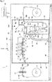
- Fig. 1 is a plan view schematically showing the configuration of an inkjet printing apparatus 1 according to a preferred embodiment.
- Fig. 2 is a side view schematically showing the configuration of the inkjet printing apparatus 1 according to the preferred embodiment.
- the inkjet printing apparatus 1 is a device that records an image on a recording surface of an elongated strip-shaped recording medium 9 (printing paper, for example) by ejecting droplets of ink from a plurality of ejection heads 21 while transporting the recording medium 9 along a prescribed transport path TR1.
- Ultraviolet curable ink to be cured by irradiation with an ultraviolet ray as an electromagnetic wave is applicable to the ink used in the inkjet printing apparatus 1.
- This ink can contain a curing initiator as a component for facilitating curing, for example.
- the inkjet printing apparatus 1 has an image recording area A1 and an electric component area A2.
- the electric component area A2 is an area for allocation of electric devices, pipes, and others.
- the electric component area A2 is surrounded by a rectangular electric component housing 100 as viewed from the upper side.
- the electric component housing 100 includes a partition wall 101 for demarcation on the +Y side, a partition wall 102 for demarcation on the -Y side, a partition wall 103 for demarcation on the +X side, and a partition wall 104 for demarcation on the -X side.
- the electric component housing 100 further includes a bottom plate 105 for demarcation on the lower side and a top plate (not shown in the drawings) for demarcation on the upper side.
- the image recording area A1 is an area for implementation of a process of recording an image on the recording medium 9.
- the image recording area A1 is surrounded by a rectangular casing 90 in a plan view.
- the casing 90 includes a partition wall 91 for demarcation on the +Y side, a partition wall 92 for demarcation on the -Y side, and a door 93 for demarcation on the +X side.
- the casing 90 further includes a bottom plate 94 for demarcation on the lower side and a top plate 95 (see Fig. 2 ) for demarcation on the upper side.
- Each of the partition walls 91 and 92 has an end on the -X side connected to the partition wall 103.
- the casing 90 is demarcated on the -X side by the partition wall 103.
- the door 93 includes two plate-like members. One of the two plate-like members of the door 93 is connected through a hinge (not shown in the drawings) to an end of the partition wall 91 on the +X side, and the other is connected through a hinge (not shown in the drawings) to an end of the partition wall 92 on the +X side. As indicated by dashes in Fig. 1 , each of the plate-like members of the door 93 rotates about the hinge to open and close the door 93.
- the inkjet printing apparatus 1 includes a transport mechanism 10, an image recording section 20, a support unit 30, a process chamber 40, an inert gas supplier 50, an air discharge part 60, an irradiation unit 70, and a controller 80.
- the image recording section 20, the support unit 30, the process chamber 40, the inert gas supplier 50, the air discharge part 60, and the irradiation unit 70 are arranged inside the casing 90 in the image recording area A1.
- the controller 80 is arranged inside the electric component housing 100 in the electric component area A2.
- a part of the transport mechanism 10 (including an unwinding roller 11 and a winding roller 14, for example) is arranged outside the casing 90.
- the transport mechanism 10 is a mechanism for transporting the recording medium 9 in a moving direction conforming to a longitudinal direction of the recording medium 9.
- the transport mechanism 10 includes the unwinding roller 11, a plurality of transport rollers 12, a chill roller 13, the winding roller 14, and a rotary driver 16.
- the transport rollers 12 include a transport roller 121, a transport roller 122, and a nip roller 123 described later.
- the recording medium 9 is unwound from the unwinding roller 11 and transported along the transport path TR1 composed of the transport rollers 12.
- Each of the transport rollers 12 rotates about a horizontal axis to guide the recording medium 9 downstream of the moving direction. After the transport of the recording medium 9, the recording medium 9 is collected on the winding roller 14.
- the recording medium 9 is supported by the transport rollers 12, the chill roller 13 and others arranged at prescribed positions to be transported along the prescribed transport path TR1.
- the rotary driver 16 rotates the unwinding roller 11, the winding roller 14, and the chill roller 13 while synchronizing these rollers with each other.
- the rotary driver 16 is arranged inside the electric component housing 100 in the electric component area A2.
- the nip roller 123 rotates actively at a constant speed while contacting a recording surface 9a and a rear surface 9b of the recording medium 9 and grasping the recording medium 9.
- the transport mechanism 10 adjusts the rotation speed of the unwinding roller 11 according to the rotation speed of the nip roller 123. This applies tension to the recording medium 9. As a result, sags or creases of the recording medium 9 are reduced during the transport.
- a direction of moving the recording medium 9 along the transport path TR1 may simply be called a "moving direction.”
- the X direction is perpendicular to the moving direction and conforms to a width direction parallel to a surface of the recording medium 9.
- a downstream side of the moving direction may simply be called “a downstream side”
- an upstream side of the moving direction may simply be called “an upstream side.”
- the cleaner 15 includes a plurality of suction rollers 151 arranged proximately vertically.
- the suction rollers 151 rotate while contacting the recording surface 9a and the rear surface 9b of the recording medium 9. Foreign matters adhering to the recording surface 9a and the rear surface 9b of the recording medium 9 are adsorbed on the suction rollers 151 and removed. By doing so, the number of foreign matters adhering to the recording medium 9 before printing is reduced. This reduces the occurrence of a printing defect such as rejection or exuding of ink due to foreign matters.
- the cleaner 15 may be equipped with another system (such as a suction mechanism) other than the suction rollers 151.
- the recording medium 9 moves into the casing 90 through an inlet 90A formed at the partition wall 92 of the casing 90. Then, the recording medium 9 moves under the image recording section 20 substantially horizontally in a direction in which the ejection heads 21 are aligned. During the move under the image recording section 20, the recording surface 9a of the recording medium 9 is pointed upward (toward the ejection heads 21).
- the image recording section 20 is a mechanism that ejects ultraviolet-curable ink to the recording medium 9 transported by the transport mechanism 10.
- the image recording section 20 of the preferred embodiment includes four ejection heads 21.
- the four ejection heads 21 are aligned in the moving direction of the recording medium 9.
- droplets of ink of each color of C (cyan), M (magenta), Y (yellow), and K (black) are ejected from the four ejection heads 21 respectively toward the recording surface 9a of the recording medium 9.
- the droplets of each color ink become color components of a color image.
- the color image is formed on the recording surface 9a of the recording medium 9.
- a step of ejecting the ink from the ejection head 21 to the recording medium 9 is an example of an ink ejection step.
- the support unit 30 includes a plurality of support tables 31 aligned in the moving direction of the recording medium 9.
- the four ejection heads 21 are each attached to one of these support tables 31. In this way, the four ejection heads 21 are supported and the positions of these heads relative to each other are fixed.
- Each of the support tables 31 has a through hole 311 formed at the center of the support table 31. A lower end of the ejection head 21 is inserted into through hole 311. In this way, the lower surface of the ejection head 21 attached to the support table 31 is caused to face the recording surface 9a of the recording medium 9 without being blocked by the support table 31.
- Fig. 3 is a vertical sectional view of the ejection head 21 and the support table 31.
- the lower surface of each ejection head 21 is provided with a plurality of nozzles 211 for ejecting droplets of ink.
- the nozzles 211 are aligned regularly in the width direction of the recording medium 9 perpendicular to the moving direction of the recording medium 9 in such a manner as to cover the width of the recording medium 9 substantially entirely.
- the ejection head 21 is fixed to the support table 31 while the lower end of the ejection head 21 is fitted in the through hole 311 of the support table 31.
- the lower surface of the ejection head 21 is a nozzle surface 212 where the nozzles 211 are formed.
- the transport roller 121 as a switcher is arranged downstream as viewed from the image recording section 20.
- the transport roller 121 rotates about a horizontal axis extending in the X direction while contacting the rear surface 9b of the recording medium 9. This bends the recording medium 9 to a direction opposing the recording surface 9a.
- the moving direction of the recording medium 9 is switched from a first direction (a substantially horizontal direction) to a second direction (a vertically downward direction).
- the process chamber 40 is provided inside the casing 90.
- the process chamber 40 includes a partition wall 41 for demarcation on the -Y side and a door 43 for demarcation on the +X side.
- the process chamber 40 is demarcated on the +Y side by the partition wall 91 and is demarcated on the -X side by the partition wall 103.
- the partition wall 41 has an end on the -X side connected to the partition wall 103.
- the door 43 has an end on the +Y side connected to the partition wall 91 through a hinge (not shown in the drawings).
- the process chamber 40 includes a plate-like top plate 45 for demarcation on the upper side.
- the interior of the casing 90 is partitioned by the partition wall 41, the door 43, and the top plate 45 into the process chamber 40 and a printing chamber 97.
- the image recording section 20 described above is arranged inside the printing chamber 97.
- the process chamber 40 includes an inlet 40A (first inlet) and an outlet 40B (first outlet).
- the inlet 40A and the outlet 40B are rectangular openings.
- the transport mechanism 10 transports the recording medium 9 into the process chamber 40 through the inlet 40A.
- the transport mechanism 10 transports the recording medium 9 in the process chamber 40 to the outside of the process chamber 40 through the outlet 40B.
- the inlet 40A is formed at the top plate 45.
- the outlet 40B is formed at the partition wall 91.
- the inlet 40A is arranged downstream from the image recording section 20.
- the process chamber 40 has internal space R1 communicating through the inlet 40A with internal space R2 in the casing 90 (printing chamber 97).
- the "communicating state" means a state of being connected in a manner allowing passage of a fluid.
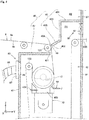
- Fig. 4 is a sectional view schematically showing a part of the process chamber 40.
- the top plate 45 includes a first plate 46 located on the +Y side and a second plate 47 located on the -Y side.
- the first plate 46 has an end on the +Y side connected to a surface of the partition wall 91 on the -Y side.
- the first plate 46 includes a horizontal section 461 extending in the -Y direction from the partition wall 91, a vertical section 463 extending toward the lower side from a tip of the horizontal section 461, and a tilting section 465 extending downward in the -Y direction from a tip of the vertical section 463.
- the tilting section 465 has a tip 466 facing the outer peripheral surface of the transport roller 121.
- the tip 466 extends in the X direction (width direction) parallel to the outer peripheral surface of the transport roller 121 and forms a certain gap between the tip 466 and the outer peripheral surface of the transport roller 121.
- the second plate 47 has an end on the -Y side connected to the upper end of the partition wall 41.
- the second plate 47 extends in the +Y direction from the upper end of the partition wall 41 to a position below the transport roller 121.
- the second plate 47 has an end on the +Y side facing the rear surface 9b of the recording medium 9 pointed from the transport roller 121 toward the chill roller 13.
- the inlet 40A is composed of the tip 466 of the tilting section 465, a tip 471 of the second plate 47, a connector 48 connecting respective ends of the tips 466 and 471 on the -X side, and a connector (not shown in the drawings) connecting respective ends of the tips 466 and 471 on the +X side.
- the transport roller 121 is partially arranged inside the inlet 40A.
- Tension is applied to a part of the recording medium 9 supported by the transport roller 121 to suppress fluttering of the recording medium 9. For this reason, even if a tip of the tilting section 465 forming the inlet 40A is moved closer to the transport roller 121, the recording medium 9 is still prevented from contacting the tip of the tilting section 465. This allows narrowing of the gap between the tip 466 of the inlet 40A and the transport roller 121.
- Fig. 5 is a side view schematically showing the irradiation unit 70 and its vicinity in the inkjet printing apparatus 1.
- the chill roller 13 rotates about a horizontal axis 131 extending in the X direction while contacting the rear surface 9b of the recording medium 9.
- the horizontal axis 131 is rotatably supported by side walls 133 of the chill roller 13 arranged on the +X side and the -X side.
- the rotary axis of the transport roller 122 may also be supported on the side walls 133.
- the horizontal axis 131 is connected to the rotary driver 16 through an opening 111 at the partition wall 103.
- the chill roller 13 has a greater outer diameter than the transport rollers 121 and 122.
- the chill roller 13 is arranged substantially vertical above an irradiation chamber 400 and the irradiation unit 70.
- the chill roller 13 has an outer peripheral surface 13S. The diameter of the outer surface 13S is greater than the diameter of an outer peripheral surfaces of the transport rollers 12.
- Coolant 130 is stored inside the chill roller 13.
- the coolant 130 is circulated appropriately by a circulation device not shown in the drawings.
- the circulation device may be provided in a part of the interior of the electric component housing 100.
- the coolant 130 is used for cooling the surface of the chill roller 13 and maintaining the surface at a certain temperature.
- a structure, a mechanism, and others for storing and circulating the coolant 130 are examples of a cooling mechanism.
- the irradiation chamber 400 is arranged inside the process chamber 40.
- the irradiation chamber 400 is arranged downstream from a position where ink from the ejection head 21 is to adhere to the recording medium 9.
- the irradiation chamber 400 is demarcated on the upper side by the chill roller 13, demarcated on the lower side by a housing 73 of the irradiation unit 70, demarcated on the +Y side by a block 401, and demarcated on the -Y side by a block 403.
- the irradiation chamber 400 is further demarcated on the +X side and the -X side by the respective side walls 133. In this way, the irradiation chamber 400 forms substantially enclosed irradiation space 40R.
- the blocks 401 and 403 have respective upper surfaces that are curved surfaces of arc-like shapes corresponding to the outer peripheral surface 13S of the chill roller 13. A certain gap is formed between each of these upper surfaces and the outer peripheral surface 13S.
- the block 401 has an upstream end forming an inlet 411 (second inlet) together with the outer peripheral surface 13S.
- the block 403 has a downstream end forming an outlet 413 (second outlet) together with the outer peripheral surface 13S.
- the outer peripheral surface 13S and the upper surface of the block 401 form a first flow path 421.
- the outer peripheral surface 13S and the upper surface of the block 403 form a second flow path 423.
- the recording medium 9 supported by the chill roller 13 passes through the inlet 411, the first flow path 421, and the irradiation space 40R sequentially.
- the recording medium 9 passes through irradiation space 40R, the second flow path 423, and the outlet 413 sequentially to move out of the irradiation chamber 400.
- the irradiation chamber 400 is provided with an oximeter 431.
- the oximeter 431 measures an oxygen concentration in the irradiation space 40R, and outputs a signal indicating a result of the measurement to the controller 80.
- the inert gas supplier 50 supplies an inert gas into the irradiation chamber 400.
- the inert gas supplier 50 has a supply port 51 for supplying nitrogen gas toward the recording surface 9a of the recording medium 9.
- An inert gas source 54 which is composed of a gas cylinder, for example, is connected to the supply port 51 through a pipe 52 and an open/close valve 53. Opening and closing the open/close valve 53 controls supply of nitrogen gas from the inert gas source 54 to the supply port 51. By executing opening control of the open/close valve 53, the amount of supply of nitrogen gas is controlled.
- a pressure adjusting mechanism of adjusting the pressure of nitrogen gas supplied from the supply port 51 may be provided separately from the open/close valve 53.
- the supply port 51 may be provided with an additional ejection mechanism such as what is called an air knife.
- the pipe 52 and the open/close valve 53 are arranged inside the electric component housing 100.
- the inert gas source 54 is arranged outside the electric component housing 100, and the pipe 52 extends to the outside of the electric component housing 100.
- the inert gas source 54 may be provided inside the electric component housing 100.
- supplying an inert gas to the irradiation chamber 400 can be understood as supplying the inert gas to the process chamber 40.
- a step implemented by the inert gas supplier 50 of supplying the inert gas into the irradiation chamber 400 is an example of an inert gas supply step.
- the supply port 51 is formed at the upper surface of the block 401 facing the chill roller 13. Nitrogen gas emitted from the supply port 51 moves downstream in the first flow path 421 together with the recording medium 9 being moved by the chill roller 13. In this way, the irradiation space 40R is filled with the nitrogen gas to allow an oxygen concentration in the irradiation space 40R to be reduced relatively.
- the supply port 51 faces the recording surface 9a of the recording medium 9. This allows impinging of the nitrogen gas on the recording surface 9a to achieve efficient replacement of atmosphere on the recording surface 9a with the nitrogen gas. Supplying the nitrogen gas into the irradiation chamber 400 narrower than the process chamber 40 allows a nitrogen concentration around a surface of the recording medium 9 to be increased more efficiently than in a case of supplying the nitrogen gas into the process chamber 40.
- the irradiation unit 70 is arranged downstream from the inert gas supplier 50 and substantially vertically below the chill roller 13.
- the irradiation unit 70 is arranged directly below the irradiation chamber 400.
- the irradiation unit 70 performs an irradiation process of irradiating the recording medium 9 supported by the chill roller 13 with irradiation light.
- the irradiation unit 70 of the preferred embodiment includes a metal halide lamp 71, a reflector 72, and the housing 73.
- the metal halide lamp 71 is a tubular light source extending in the X direction.
- the reflector 72 has a U-shape opened upward as viewed from the +X side.
- the metal halide lamp 71 is arranged inside the reflector 72.
- the housing 73 accommodates the metal halide lamp 71 and the reflector 72.
- the housing 73 has a shape like a rectangular parallelepiped and has an upper section made of a material having
- Irradiation light emitted from the metal halide lamp 71 contains an ultraviolet ray (electromagnetic wave) in a wavelength band effective in curing ink ejected from the ejection head 21.
- the irradiation light emitted from the metal halide lamp 71 has a light quantity sufficient for curing the ink completely.
- the ink is cured to fix the ink to the recording medium 9. As a result, an image is recorded on the recording surface 9a of the recording medium 9.
- a step performed by the irradiation unit 70 of irradiating the recording surface 9a of the recording medium 9 with an ultraviolet ray inside the irradiation chamber 400 is an example of an irradiation step.
- the recording medium 9 passes through the irradiation unit 70, the recording medium 9 passes through the chill roller 13 and a plurality of rollers including the transport roller 122 and the nip roller 123 to be collected on the winding roller 14.
- the irradiation unit 70 irradiates a part of the recording medium 9 supported by the chill roller 13, namely, a part of the recording medium 9 contacting the chill roller 13 with an ultraviolet ray. In this case, temperature increase of the recording medium 9 caused by the irradiation process is suppressed.
- the recording medium 9 is bent by the chill roller 13 to an opposing direction to switch an advancing direction of the recording medium 9.
- a switching angle of the advancing direction determined by the chill roller 13 is preferably equal to or greater than 180 degrees. In this case, the recording medium 9 contacts the chill roller 13 for a longer period of time to be cooled sufficiently. In this way, temperature increase of the recording medium 9 caused by the irradiation process is suppressed.
- the recording medium 9 receives tension applied by being supported by the chill roller 13. This reduces sags or creases of the recording medium 9 to be caused by thermal expansion.
- a part of the partition wall 103 facing the interior of the process chamber 40 (a part facing the door 43) is provided with the rectangular opening 111 as a through hole.
- Fig. 6 shows the opening 111 and its vicinity at the partition wall 103.
- Fig. 7 shows the opening 111 to which the partition member 113 is attached.
- the plate-like partition member 113 is provided inside the opening 111.
- the partition member 113 has a rectangular opening 114 formed at the center of the partition member 113.
- the partition member 113 includes a rubber wall 115 on the lower side and an iron plate 119 on the upper side.
- the rubber wall 115 has a recess 116 depressed toward the lower side formed at the center of the top of the rubber wall 115.
- the iron plate 119 has a recess 120 depressed toward the upper side formed at the center of the bottom of the iron plate 119.
- the recess 116 and the recess 120 are combined in the Z direction to form the opening 114 as a through hole.
- the interior of the process chamber 40 communicates with the outside of the process chamber 40 (more specifically, with the interior of the electric component housing 100) through the opening 114.
- the recess 116 of the rubber wall 115 has an inner edge provided with a plurality of slits 117 extending toward the outer edge of the rubber wall 115 and spaced at predetermined intervals in the Z direction.
- the recess 116 is located at the height of the irradiation unit 70 to be fitted in the process chamber 40.
- the housing 73 of the irradiation unit 70 is inserted into the recess 116.
- the horizontal axis 131 of the chill roller 13 is passed through inside the recess 120 of the iron plate 119.
- Figs. 8 and 9 are sectional views both taken at a position along a line A-A in Fig. 7 .
- the door 93 of the casing 90 is opened and the door 43 of the process chamber 40 is opened (see Fig. 1 ).
- the irradiation unit 70 is transported into the process chamber 40.
- the housing 73 of the irradiation unit 70 is inserted into the recess 116 of the rubber wall 115.
- the housing 73 is installed inside the process chamber 40 with an end of the housing 73 on the +X side protruding into the electric component area A2, as shown in Fig. 9 .
- a connector such as electric wires 701 in the electric component area A2 is connected appropriately to a connection interface provided at an end surface of the housing 73 on the +X side.
- the recess 116 has a width W1 in the Y direction less than a width W2 of the housing 73 in the Y direction.
- the inner edge of the recess 116 is caused to contact the outer surface of the housing 73 to deform in such a manner as to collapse toward the -X side.
- the slits 117 at the inner edge of the recess 116 the inner edge of the recess 116 deforms easily to follow the outer shape of the housing 73. This makes it possible to reduce a gap between the opening 114 defined by the inner edge of the recess 116 and the housing 73.
- the process chamber 40 is given increased hermeticity. This particularly acts to suppress move of atmosphere containing nitrogen gas inside the process chamber 40 into the electric component housing 100 in the electric component area A2. In this way, move of the atmosphere containing the nitrogen gas from inside the electric component housing 100 toward the printing chamber 97 is suppressed.
- the housing 73 is not always required to be installed in such a manner as to protrude into the electric component area A2.
- the housing 73 may alternatively be installed in such a manner as to be accommodated entirely inside the process chamber 40.
- an electric wire bundle with the electric wires 701 tied together may be passed through the recess 116 of the rubber wall 115.
- the recess 116 may be formed into a shape conforming to the outer shape of the electric wire bundle.
- the inner edge of the recess 116 may be deformed to follow the outer shape of the electric wire bundle by making the inner diameter of the recess 116 less than the outer diameter of the electric wire bundle. This allows reduction in a gap between the recess 116 and the electric wire bundle.
- the air discharge part 60 discharges air inside the process chamber 40 to the outside of the process chamber 40 and to the outside of the casing 90.
- the air discharge part 60 includes a first exhaust fan 61, a second exhaust fan 63, an exhaust duct 65, and a duct connector 67.
- the first exhaust fan 61 is provided at a position of the partition wall 91 facing the interior of the process chamber 40.
- the first exhaust fan 61 is located closer to the upper side than the outlet 40B.
- the first exhaust fan 61 is attached to overlap a through hole formed at the partition wall 91.
- a discharge side of the first exhaust fan 61 communicates with the outside of the casing 90.
- atmosphere inside the process chamber 40 is discharged to the outside of the process chamber 40 and to the outside of the casing 90.
- the second exhaust fan 63 is provided at the bottom plate 94 forming a lower part of the casing 90.
- the second exhaust fan 63 is arranged closer to the -Y side than the partition wall 41.
- One end of the exhaust duct 65 is connected to the second exhaust fan 63.
- the other end of the exhaust duct 65 is connected to the duct connector 67.
- the duct connector 67 is attached to an opening 44 as an through hole formed at the partition wall 41.
- the duct connector 67 is attached in a removable manner to the partition wall 41. Removing the duct connector 67 from the partition wall 41 allows the interior of the process chamber 40 to be checked visually through the opening 44 and allows implementation of work inside the process chamber 40 with a hand put into the process chamber 40. As shown in Fig. 2 , for example, the opening 44 is located at the same height as the transport roller 122 in the Z direction. In the inkjet printing apparatus 1, placement work is done for placing the recording medium 9 along the transport path TR1 from the unwinding roller 11 to the winding roller 14. More specifically, a user does this work by pulling the recording medium 9 from the unwinding roller 11 and then putting the recording medium 9 over each of the transport rollers 12 or over the chill roller 13, for example.
- the user is allowed to put the recording medium 9 over the transport roller 122, for example, from the outside of the process chamber 40 through the opening 44.
- the user is also allowed to do maintenance work on each element in the process chamber 40 through the opening 44.
- the air discharge part 60 includes a barometer 691 and a barometer 693.
- the barometer 691 is provided inside the process chamber 40 and used for measuring an internal pressure in the process chamber 40.
- the barometer 693 is provided inside the printing chamber 97 and used for measuring an internal pressure in the printing chamber 97.
- the barometers 691 and 693 transmit signals indicating measured barometric pressure values to the controller 80.
- Nitrogen gas supplied to the irradiation chamber 400 moves into the process chamber 40 through the inlet 411 or the outlet 413, for example. If atmosphere containing a large quantity of the nitrogen gas inside the process chamber 40 moves toward the ejection head 21 and its vicinity in the printing chamber 97 through the inlet 40A, for example, the characteristics of ink (wettability, for example) adhering to the recording medium 9 may be changed to cause a likelihood of reduction in printing quality.
- the first and second exhaust fans 61 and 63 of the air discharge part 60 discharge the atmosphere in the process chamber 40 to the outside of the casing 90. This reduces move of the atmosphere inside the process chamber 40 to the printing chamber 97. In this way, it becomes possible to suppress move of the atmosphere containing the nitrogen gas to the ejection head 21 to alleviate reduction in printing quality.
- the nitrogen gas leaking from the irradiation chamber 400 into the process chamber 40 is lighter than air, so that it is prone to move to be closer to the upper side than the irradiation chamber 400.
- the first exhaust fan 61 is provided closer to the upper side than the irradiation chamber 400.
- the opening 44 which is an intake port of the second exhaust fan 63, is also provided closer to the upper side than the irradiation chamber 400.
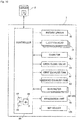
- Fig. 10 shows electrical connection of the controller 80 in the inkjet printing apparatus 1.
- the controller 80 is configured using a computer including a calculation processing unit 81 such as a CPU, a memory 82 such as a RAM, and an auxiliary memory 83 such as a hard disc.
- the controller 80 is connected to each of the rotary driver 16, the four ejection heads 21, the oximeter 431, the open/close valve 53, the first exhaust fan 61, the second exhaust fan 63, the barometers 691 and 693, the irradiation unit 70, and the nip roller 123.
- the controller 80 controls the motion of each element connected to the irradiation unit 70 by causing the calculation processing unit 81 to execute a computer program P installed on the auxiliary memory 83.
- a printing process proceeds in the inkjet printing apparatus 1 under the control by the controller 80.
- the controller 80 may electrically be connected to a server 2 installed external to the inkjet printing apparatus 1.
- the server 2 stores image data D to be printed, for example.
- the recording medium 9 is transported by the transport mechanism 10, and the controller 80 reads the designated image data D from the server 2 and ejects ink of each color from a corresponding one of the ejection heads 21 on the basis of the image data D.
- an image responsive to the image data D is recorded on the recording surface 9a of the recording medium 9.
- the image data D may be provided to the controller 80 without intervention of the server 2.
- the controller 80 may control the open/close valve 53 in response to output from the oximeter 431. More specifically, if an oxygen concentration indicated by the oximeter 431 is higher than a predetermined threshold, the controller 80 may increase the amount of supply of nitrogen gas from the supply port 51 by controlling the open/close valve 53. This allows reduction in the oxygen concentration in the irradiation chamber 400, so that the oxygen concentration in the irradiation chamber 400 is maintained at a level suitable for curing of ink.
- the controller 80 may control the first and second exhaust fans 61 and 63 in response to the amount of supply per unit time (hereinafter simply called “the amount of supply”) of nitrogen gas from the supply port 51. More specifically, the controller 80 may control the first and second exhaust fans 61 and 63 in terms of rotation number, for example, in such a manner that the amount of supply of the nitrogen gas by the inert gas supplier 50 becomes less than the amount of discharge per unit time (hereinafter simply called "the amount of discharge”) of atmosphere by the first and second exhaust fans 61 and 63.
- the controller 80 may control the first and second exhaust fans 61 and 63 in response to outputs from the barometers 691 and 693. More specifically, the controller 80 may control the first and second exhaust fans 61 and 63 in such a manner that an internal pressure in the process chamber 40 indicated by the barometer 691 becomes less than an internal pressure in the printing chamber 97 indicated by the barometer 693. By the execution of this control, it becomes possible to suppress move of atmosphere containing nitrogen gas inside the process chamber 40 into the printing chamber 97. In this way, move of the atmosphere containing the nitrogen gas toward the ejection head 21 and its vicinity is suppressed to alleviate reduction in printing quality.
- Control of the first and second exhaust fans 61 and 63 by the controller 80 is not an absolute necessity.
- the amount of discharge by the first and second exhaust fans 61 and 63 may be made sufficiently greater than the amount of supply of nitrogen gas by the inert gas supplier 50.
- an internal pressure in the process chamber 40 may be made less than an internal pressure in the printing chamber 97 by increasing the amount of discharge by the first and second exhaust fans 61 and 63 sufficiently.
- the support unit 30 of the image recording section 20 includes the four support tables 31, and the ejection heads 21 are each attached to one of these support tables 31.
- a pre-curing unit 23 for emitting light toward the recording medium 9 may be attached to the support table 31.
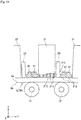
- Fig. 11 is a vertical sectional view of the support unit 30 and the support table 31 according to a modification.
- the pre-curing unit 23 is a member that emits an electromagnetic wave (ultraviolet ray) toward the recording medium 9 to pre-cure ink ejected on the recording medium 9. As shown in Fig.
- the pre-curing unit 23 is attached onto the support table 31 to be located downstream from the ejection head 21 of the Y direction. Pre-curing the ink on the recording medium 9 using the pre-curing unit 23 allows the irradiation unit 70 to more efficiently cure the ink on the recording medium 9 completely.
- the viscosity of the ink on the recording medium 9 is increased slightly by the light from the pre-curing unit 23. Increase in the viscosity of the ink reduces wettability. If the ink of the increased viscosity is exposed to low-oxygen atmosphere, the increase in the viscosity and the exposure to the low-oxygen atmosphere achieve a synergistic effect to cause a likelihood of further reduction in the wettability of the ink. In response to this, in the inkjet printing apparatus 1, leakage of nitrogen gas in the internal space R1 in the process chamber 40 into the internal space R2 in the casing 90 is suppressed to make it unlikely that the internal space R2 will be placed in low-oxygen atmosphere. Thus, even in the presence of the pre-curing unit 23 attached to the image recording section 20, reduction in the wettability of the ink is still suppressed to ensure printing quality.
- the viscosity of ink on the recording medium 9 is also increased slightly if the interior of the casing 90 is placed in a high temperature by a device such as a power supply. If the ink on the recording medium 9 is exposed to low-oxygen atmosphere while the viscosity of the ink is increased by the temperature increase, the viscosity of the ink is increased further to cause a likelihood of reduction in wettability. In response to this, in the inkjet printing apparatus 1, the occurrence of low-oxygen atmosphere in the internal space R2 is reduced. Thus, even if the interior of the casing 90 is placed in a high temperature for some reason, reduction in the wettability of the ink is still suppressed to ensure printing quality.
- the inkjet printing apparatus 1 described above is to record an image on printing paper as a recording medium.
- the inkjet printing apparatus of the present invention may be configured to record an image on a strip-shaped recording medium other than paper generally used (a resin film, for example).
- nitrogen gas available at low cost is used as the inert gas supplied from the supplier.
- the inert gas may be a different type of gas such as helium or argon, or a mixed gas of such gases.
- an electromagnetic wave emitted from the irradiation unit is an ultraviolet ray.
- the irradiation unit may be configured to emit an electromagnetic wave other than ultraviolet light.
- the transport mechanism 10 is a mechanism of a roll-to-roll system.
- the transport mechanism of the present invention is not limited to this system.
- the transport mechanism may be a mechanism of an adsorption carrying method of adsorbing and transporting a recording medium using a belt wound around a pair of rollers and an adsorbing device provided to the belt. If the adsorption carrying method is used for the transport mechanism, a sheet-fed recording medium may be used instead of a strip-shaped recording medium.
Landscapes
- Health & Medical Sciences (AREA)
- General Health & Medical Sciences (AREA)
- Toxicology (AREA)
- Ink Jet (AREA)
Abstract
Description
- The present invention relates to an inkjet printing apparatus and an inkjet printing method.
- There is an inkjet printing apparatus that transports a strip-shaped recording medium and records an image on a surface of the recording medium by ejecting ink from multiple heads. In this type of inkjet printing apparatus, ink to be cured in response to irradiation with an active energy ray such as an ultraviolet ray or an electron ray is used in some cases. In such cases, after the ink is ejected to a recording surface of the recording medium, ink adhering to the recording medium is irradiated with active energy. This causes the ink to be cured and an image to be printed on the recording medium. Curing the ink through irradiation with the active energy ray is known to inhibit curing of the ink as a result of influence of oxygen around the ink. For curing the ink efficiently, an oxygen concentration around the ink is desirably reduced by replacing an air layer on the surface of the recording medium with an inert gas, for example.
- A technique for reduction in oxygen concentration on the surface of the recording medium is disclosed in Japanese Patent Application Laid-Open No.
2012-166539 2012-166539 2012-166539 - The conventional technique causes a likelihood that the inert gas supplied for ink curing will move from an irradiation area of irradiation with the active energy ray to an ejection area of ink ejection. Increase in inert gas concentration in the ejection area causes relative reduction in oxygen concentration, and this may cause change in characteristic (wettability, for example) of the ink. In the case of ultraviolet-curable ink, for example, reduction in oxygen concentration increases viscosity to reduce wettability. This makes it difficult for the ink adhering to a recording medium to spread over the recording medium sufficiently, causing a risk of reduction in printing quality due to the occurrence of a pin hole, for example.
- An object of the present invention is to provide a technique of alleviating reduction in printing quality to be caused by inert gas during printing of an inkjet system.
- A first aspect is intended for an inkjet printing apparatus that records an image by ejecting electromagnetic curing type ink to a recording medium. The inkjet printing apparatus includes: a casing; a transport mechanism that transports a recording medium inside the casing along a prescribed transport path; an ejection head arranged inside the casing and ejecting the ink to the recording medium; a process chamber having a first inlet and a first outlet arranged downstream from the ejection head and for passage of the recording medium, the process chamber communicating with the interior of the casing through the first inlet; an irradiation unit that irradiates the recording medium inside the process chamber with an electromagnetic wave; an inert gas supplier that supplies an inert gas into the process chamber; and an air discharge part that discharges atmosphere inside the process chamber to the outside of the process chamber and to the outside of the casing. An internal pressure in the process chamber is less than an internal pressure in the casing.
- According to a second aspect, in the inkjet printing apparatus according to the first aspect, the amount of supply of the inert gas by the inert gas supplier is less than the amount of discharge of the atmosphere by the air discharge part.
- According to a third aspect, the inkjet printing apparatus according to the first or second aspect further includes an irradiation chamber arranged inside the process chamber and having a second inlet and a second outlet for passage of the recording medium. The irradiation unit irradiates the recording medium inside the irradiation chamber with the electromagnetic wave. The inert gas supplier supplies the inert gas into the irradiation chamber.
- According to a fourth aspect, in the inkjet printing apparatus according to the third aspect, the inert gas contains gas lighter than air, and the air discharge part discharges the atmosphere through an intake port provided at the process chamber and at a higher position than the irradiation chamber.
- According to a fifth aspect, in the inkjet printing apparatus according to the fourth aspect, the air discharge part includes an exhaust duct connected to the intake port. The exhaust duct is fitted in a removable manner to the intake port.
- According to a sixth aspect, in the inkjet printing apparatus according to any one of the first to fifth aspects, the first outlet communicates with the outside of the casing.
- According to a seventh aspect, the inkjet printing apparatus according to any one of the first to sixth aspects further includes a door for opening and closing the process chamber .
- According to an eighth aspect, in the inkjet printing apparatus according to any one of the first to seventh aspects, a part of a partition member surrounding the process chamber includes a rubber wall made of rubber and forming an opening communicating with the outside of the process chamber, the rubber wall contacts an outer surface of a contained object arranged inside the process chamber, and at least a part of the contained object is arranged beyond the process chamber through the opening.
- According to a ninth aspect, the inkjet printing apparatus according to any one of the first to eighth aspects further includes a chill roller arranged inside the process chamber. The chill roller cools the recording medium while supporting the recording medium on an outer peripheral surface of the chill roller.
- According to a tenth aspect, in the inkjet printing apparatus according to the ninth aspect, the irradiation unit is arranged inside the process chamber and irradiates a part of the recording medium supported by the chill roller with the electromagnetic wave.
- According to an eleventh aspect, in the inkjet printing apparatus according to any one of the first to tenth aspects, the air discharge part discharges the atmosphere to the outside of the casing from a lower part of the casing.
- According to a twelfth aspect, in the inkjet printing apparatus according to any one of the first to eleventh aspects, the transport mechanism includes a transport roller extending in a width direction of the recording medium, and an edge of the first inlet extends parallel to the transport roller while facing the transport roller.
- According to a thirteenth aspect, the inkjet printing apparatus according to any one of the first to twelfth aspects further includes a pre-curing unit that emits an electromagnetic wave for pre-curing the ink ejected from the ejection head toward the recording medium.
- A fourteenth aspect is intended for an inkjet printing method of recording an image by ejecting electromagnetic curing type ink to a recording medium. The inkjet printing method includes: (a) a transport step of transporting a recording medium inside a casing along a prescribed transport path; (b) an ink ejection step of ejecting the ink to the recording medium from an ejection head arranged inside the casing; (c) an incoming step of transporting the recording medium into a process chamber having a first inlet and a first outlet through the first inlet, the first inlet being arranged downstream from the ejection head and communicating with the interior of the casing, the first outlet being arranged downstream from the first inlet; (d) an irradiation step of irradiating the recording medium with an electromagnetic wave inside the process chamber; (e) an inert gas supply step of supplying an inert gas into the process chamber; (f) an outgoing step of transporting the recording medium to the outside of the process chamber through the first outlet of the process chamber; and (g) an air discharge step of discharging atmosphere inside the process chamber to the outside of the process chamber and to the outside of the casing. An internal pressure in the process chamber is less than an internal pressure in the casing.
- In the inkjet printing apparatus according to the first aspect, the atmosphere inside the process chamber is discharged to the outside of the process chamber and to the outside of the casing. Further, an internal pressure in the process chamber is less than an internal pressure in the casing. Thus, it becomes possible to suppress move of the atmosphere containing the inert gas from the process chamber into the casing. In this way, move of the atmosphere containing the inert gas toward the ejection head and its vicinity is suppressed to alleviate reduction in printing quality.
- The inkjet printing apparatus according to the second aspect allows suppression of move of the atmosphere containing the inert gas in the process chamber from the process chamber into the casing.
- In the inkjet printing apparatus according to the third aspect, supplying the inert gas into the irradiation chamber narrower than the process chamber allows an inert gas concentration inside the irradiation chamber to be increased easily.
- In the inkjet printing apparatus according to the fourth aspect, as the inert gas is lighter than air, the inert gas leaking from the irradiation chamber into the process chamber moves closer to an upper side than the irradiation chamber. In this regard, discharging the atmosphere inside the process chamber through the intake port at a higher position than the irradiation chamber allows the inert gas to be discharged efficiently from the process chamber.
- In the inkjet printing apparatus according to the fifth aspect, removing the exhaust duct allows implementation of maintenance work inside the process chamber through the intake port.
- In the inkjet printing apparatus according to the sixth aspect, move of the inert gas leaking through the first outlet into the casing is suppressed. This allows alleviation of reduction in printing quality.
- In the inkjet printing apparatus according to the seventh aspect, opening and closing the door allows the interior of the process chamber to be opened.
- In the inkjet printing apparatus according to the eighth aspect, contact of the rubber wall with the outer surface of the contained object allows the opening defined by the rubber wall to be deformed to follow the outer shape of the contained object. This achieves reduction in a gap between the opening and the contained object to achieve increased hermeticity of the process chamber.
- In the inkjet printing apparatus according to the ninth aspect, the presence of the chill roller inside the process chamber allows the recording medium to be cooled in the process chamber.
- The inkjet printing apparatus according to the tenth aspect allows irradiation with the electromagnetic wave to a part of the recording medium cooled by the chill roller.
- The inkjet printing apparatus according to the eleventh aspect allows the atmosphere inside the process chamber to be discharged to the outside of the casing from the lower part of the casing.
- In the inkjet printing apparatus according to the twelfth aspect, supporting the recording medium with the transport roller suppresses fluttering of the recording medium. For this reason, even if the first inlet and the transport roller get closer to each other, the recording medium is still prevented from contacting the first outlet.
- In the inkjet printing apparatus according to the thirteenth aspect, even if the viscosity of the ink on the recording medium is increased by the electromagnetic wave from the pre-curing unit, reduction in printing quality resulting from reduction in the wettability of the ink is still alleviated.
- In the inkjet printing method according to the fourteenth aspect, the atmosphere inside the process chamber is discharged to the outside of the process chamber and to the outside of the casing. Further, an internal pressure in the process chamber is less than an internal pressure in the casing. Thus, it becomes possible to suppress move of the atmosphere containing the inert gas from the process chamber into the casing. In this way, move of the atmosphere containing the inert gas toward the ejection head and its vicinity is suppressed to alleviate reduction in printing quality.
-
-
Fig. 1 is a plan view schematically showing the configuration of aninkjet printing apparatus 1 according to a preferred embodiment; -
Fig. 2 is a side view schematically showing the configuration of theinkjet printing apparatus 1 according to the preferred embodiment; -
Fig. 3 is a vertical sectional view of anejection head 21 and a support table 31; -
Fig. 4 is a sectional view schematically showing a part of aprocess chamber 40; -
Fig. 5 is a side view schematically showing anirradiation unit 70 and its vicinity in theinkjet printing apparatus 1; -
Fig. 6 shows anopening 111 and its vicinity at apartition wall 103; -
Fig. 7 shows theopening 111 to which apartition member 113 is attached; -
Fig. 8 is a sectional view taken at a position along a line A-A inFig. 7 ; -
Fig. 9 is a sectional view taken at the position along the line A-A inFig. 7 ; -
Fig. 10 shows electrical connection of acontroller 80 in theinkjet printing apparatus 1; and -
Fig. 11 is a vertical sectional view of theejection head 21 and the support table 31 according to a modification. - A preferred embodiment of the present invention will be described below by referring to the accompanying drawings. Constituting elements in the preferred embodiment are described merely as examples, and the scope of the present invention is not to be limited only to these elements. To facilitate understanding, the size of each part or the number of such parts in the drawings may be illustrated in an exaggerated or simplified manner, if appropriate.
- In some of the drawings, to facilitate understanding of the positions of elements relative to each other, arrows are added to show an X direction, a Y direction, and a Z direction perpendicular to each other. In the following description, the X direction and the Y direction are defined as horizontal directions parallel to a horizontal plane, and the Z direction is defined as a direction parallel to a vertical direction. A direction in which the tip of each arrow is pointed is defined as a + direction (positive direction), and a direction opposite to the former direction is defined as a - direction (negative direction). In the following description, the +Z side means an upper side, and the -Z side means a lower side.
-
Fig. 1 is a plan view schematically showing the configuration of aninkjet printing apparatus 1 according to a preferred embodiment.Fig. 2 is a side view schematically showing the configuration of theinkjet printing apparatus 1 according to the preferred embodiment. Theinkjet printing apparatus 1 is a device that records an image on a recording surface of an elongated strip-shaped recording medium 9 (printing paper, for example) by ejecting droplets of ink from a plurality of ejection heads 21 while transporting therecording medium 9 along a prescribed transport path TR1. Ultraviolet curable ink to be cured by irradiation with an ultraviolet ray as an electromagnetic wave is applicable to the ink used in theinkjet printing apparatus 1. This ink can contain a curing initiator as a component for facilitating curing, for example. - As shown in
Fig. 1 , theinkjet printing apparatus 1 has an image recording area A1 and an electric component area A2. The electric component area A2 is an area for allocation of electric devices, pipes, and others. The electric component area A2 is surrounded by a rectangularelectric component housing 100 as viewed from the upper side. Theelectric component housing 100 includes apartition wall 101 for demarcation on the +Y side, apartition wall 102 for demarcation on the -Y side, apartition wall 103 for demarcation on the +X side, and apartition wall 104 for demarcation on the -X side. Theelectric component housing 100 further includes abottom plate 105 for demarcation on the lower side and a top plate (not shown in the drawings) for demarcation on the upper side. - The image recording area A1 is an area for implementation of a process of recording an image on the
recording medium 9. The image recording area A1 is surrounded by arectangular casing 90 in a plan view. Thecasing 90 includes apartition wall 91 for demarcation on the +Y side, apartition wall 92 for demarcation on the -Y side, and adoor 93 for demarcation on the +X side. Thecasing 90 further includes abottom plate 94 for demarcation on the lower side and a top plate 95 (seeFig. 2 ) for demarcation on the upper side. Each of thepartition walls partition wall 103. Thecasing 90 is demarcated on the -X side by thepartition wall 103. - The
door 93 includes two plate-like members. One of the two plate-like members of thedoor 93 is connected through a hinge (not shown in the drawings) to an end of thepartition wall 91 on the +X side, and the other is connected through a hinge (not shown in the drawings) to an end of thepartition wall 92 on the +X side. As indicated by dashes inFig. 1 , each of the plate-like members of thedoor 93 rotates about the hinge to open and close thedoor 93. - As shown in
Fig. 2 , theinkjet printing apparatus 1 includes atransport mechanism 10, animage recording section 20, asupport unit 30, aprocess chamber 40, aninert gas supplier 50, anair discharge part 60, anirradiation unit 70, and acontroller 80. Theimage recording section 20, thesupport unit 30, theprocess chamber 40, theinert gas supplier 50, theair discharge part 60, and theirradiation unit 70 are arranged inside thecasing 90 in the image recording area A1. Thecontroller 80 is arranged inside theelectric component housing 100 in the electric component area A2. A part of the transport mechanism 10 (including an unwindingroller 11 and a windingroller 14, for example) is arranged outside thecasing 90. - The
transport mechanism 10 is a mechanism for transporting therecording medium 9 in a moving direction conforming to a longitudinal direction of therecording medium 9. Thetransport mechanism 10 includes the unwindingroller 11, a plurality oftransport rollers 12, achill roller 13, the windingroller 14, and arotary driver 16. Thetransport rollers 12 include atransport roller 121, atransport roller 122, and a niproller 123 described later. Therecording medium 9 is unwound from the unwindingroller 11 and transported along the transport path TR1 composed of thetransport rollers 12. Each of thetransport rollers 12 rotates about a horizontal axis to guide therecording medium 9 downstream of the moving direction. After the transport of therecording medium 9, therecording medium 9 is collected on the windingroller 14. In this way, therecording medium 9 is supported by thetransport rollers 12, thechill roller 13 and others arranged at prescribed positions to be transported along the prescribed transport path TR1. As shown inFig. 1 , therotary driver 16 rotates the unwindingroller 11, the windingroller 14, and thechill roller 13 while synchronizing these rollers with each other. Therotary driver 16 is arranged inside theelectric component housing 100 in the electric component area A2. - As shown in
Fig. 2 , thenip roller 123 rotates actively at a constant speed while contacting arecording surface 9a and arear surface 9b of therecording medium 9 and grasping therecording medium 9. Thetransport mechanism 10 adjusts the rotation speed of the unwindingroller 11 according to the rotation speed of thenip roller 123. This applies tension to therecording medium 9. As a result, sags or creases of therecording medium 9 are reduced during the transport. - In the following description, a direction of moving the
recording medium 9 along the transport path TR1 may simply be called a "moving direction." The X direction is perpendicular to the moving direction and conforms to a width direction parallel to a surface of therecording medium 9. In the following description, a downstream side of the moving direction may simply be called "a downstream side," and an upstream side of the moving direction may simply be called "an upstream side." - As shown in
Fig. 2 , after being unwound from the unwindingroller 11, therecording medium 9 first passes through a cleaner 15. The cleaner 15 includes a plurality ofsuction rollers 151 arranged proximately vertically. Thesuction rollers 151 rotate while contacting therecording surface 9a and therear surface 9b of therecording medium 9. Foreign matters adhering to therecording surface 9a and therear surface 9b of therecording medium 9 are adsorbed on thesuction rollers 151 and removed. By doing so, the number of foreign matters adhering to therecording medium 9 before printing is reduced. This reduces the occurrence of a printing defect such as rejection or exuding of ink due to foreign matters. The cleaner 15 may be equipped with another system (such as a suction mechanism) other than thesuction rollers 151. - After passing through the cleaner 15, the
recording medium 9 moves into thecasing 90 through aninlet 90A formed at thepartition wall 92 of thecasing 90. Then, therecording medium 9 moves under theimage recording section 20 substantially horizontally in a direction in which the ejection heads 21 are aligned. During the move under theimage recording section 20, therecording surface 9a of therecording medium 9 is pointed upward (toward the ejection heads 21). - The
image recording section 20 is a mechanism that ejects ultraviolet-curable ink to therecording medium 9 transported by thetransport mechanism 10. Theimage recording section 20 of the preferred embodiment includes four ejection heads 21. The four ejection heads 21 are aligned in the moving direction of therecording medium 9. During printing, droplets of ink of each color of C (cyan), M (magenta), Y (yellow), and K (black) are ejected from the four ejection heads 21 respectively toward therecording surface 9a of therecording medium 9. The droplets of each color ink become color components of a color image. Thus, the color image is formed on therecording surface 9a of therecording medium 9. A step of ejecting the ink from theejection head 21 to therecording medium 9 is an example of an ink ejection step. - The
support unit 30 includes a plurality of support tables 31 aligned in the moving direction of therecording medium 9. The four ejection heads 21 are each attached to one of these support tables 31. In this way, the four ejection heads 21 are supported and the positions of these heads relative to each other are fixed. Each of the support tables 31 has a throughhole 311 formed at the center of the support table 31. A lower end of theejection head 21 is inserted into throughhole 311. In this way, the lower surface of theejection head 21 attached to the support table 31 is caused to face therecording surface 9a of therecording medium 9 without being blocked by the support table 31. -
Fig. 3 is a vertical sectional view of theejection head 21 and the support table 31. The lower surface of eachejection head 21 is provided with a plurality ofnozzles 211 for ejecting droplets of ink. Thenozzles 211 are aligned regularly in the width direction of therecording medium 9 perpendicular to the moving direction of therecording medium 9 in such a manner as to cover the width of therecording medium 9 substantially entirely. Theejection head 21 is fixed to the support table 31 while the lower end of theejection head 21 is fitted in the throughhole 311 of the support table 31. The lower surface of theejection head 21 is anozzle surface 212 where thenozzles 211 are formed. - As shown in
Fig. 2 , thetransport roller 121 as a switcher is arranged downstream as viewed from theimage recording section 20. Thetransport roller 121 rotates about a horizontal axis extending in the X direction while contacting therear surface 9b of therecording medium 9. This bends therecording medium 9 to a direction opposing therecording surface 9a. As a result, the moving direction of therecording medium 9 is switched from a first direction (a substantially horizontal direction) to a second direction (a vertically downward direction). - The
process chamber 40 is provided inside thecasing 90. As shown inFig. 1 , theprocess chamber 40 includes apartition wall 41 for demarcation on the -Y side and adoor 43 for demarcation on the +X side. Theprocess chamber 40 is demarcated on the +Y side by thepartition wall 91 and is demarcated on the -X side by thepartition wall 103. Thepartition wall 41 has an end on the -X side connected to thepartition wall 103. Thedoor 43 has an end on the +Y side connected to thepartition wall 91 through a hinge (not shown in the drawings). As shown inFig. 2 , theprocess chamber 40 includes a plate-liketop plate 45 for demarcation on the upper side. The interior of thecasing 90 is partitioned by thepartition wall 41, thedoor 43, and thetop plate 45 into theprocess chamber 40 and aprinting chamber 97. Theimage recording section 20 described above is arranged inside theprinting chamber 97. - As shown in
Fig. 2 , theprocess chamber 40 includes aninlet 40A (first inlet) and anoutlet 40B (first outlet). Theinlet 40A and theoutlet 40B are rectangular openings. Thetransport mechanism 10 transports therecording medium 9 into theprocess chamber 40 through theinlet 40A. Thetransport mechanism 10 transports therecording medium 9 in theprocess chamber 40 to the outside of theprocess chamber 40 through theoutlet 40B. Theinlet 40A is formed at thetop plate 45. Theoutlet 40B is formed at thepartition wall 91. Theinlet 40A is arranged downstream from theimage recording section 20. Theprocess chamber 40 has internal space R1 communicating through theinlet 40A with internal space R2 in the casing 90 (printing chamber 97). The "communicating state" means a state of being connected in a manner allowing passage of a fluid. -
Fig. 4 is a sectional view schematically showing a part of theprocess chamber 40. Thetop plate 45 includes afirst plate 46 located on the +Y side and asecond plate 47 located on the -Y side. Thefirst plate 46 has an end on the +Y side connected to a surface of thepartition wall 91 on the -Y side. Thefirst plate 46 includes ahorizontal section 461 extending in the -Y direction from thepartition wall 91, avertical section 463 extending toward the lower side from a tip of thehorizontal section 461, and atilting section 465 extending downward in the -Y direction from a tip of thevertical section 463. Thetilting section 465 has atip 466 facing the outer peripheral surface of thetransport roller 121. Thetip 466 extends in the X direction (width direction) parallel to the outer peripheral surface of thetransport roller 121 and forms a certain gap between thetip 466 and the outer peripheral surface of thetransport roller 121. - The
second plate 47 has an end on the -Y side connected to the upper end of thepartition wall 41. Thesecond plate 47 extends in the +Y direction from the upper end of thepartition wall 41 to a position below thetransport roller 121. Thesecond plate 47 has an end on the +Y side facing therear surface 9b of therecording medium 9 pointed from thetransport roller 121 toward thechill roller 13. - The
inlet 40A is composed of thetip 466 of thetilting section 465, atip 471 of thesecond plate 47, aconnector 48 connecting respective ends of thetips tips transport roller 121 is partially arranged inside theinlet 40A. - Tension is applied to a part of the
recording medium 9 supported by thetransport roller 121 to suppress fluttering of therecording medium 9. For this reason, even if a tip of thetilting section 465 forming theinlet 40A is moved closer to thetransport roller 121, therecording medium 9 is still prevented from contacting the tip of thetilting section 465. This allows narrowing of the gap between thetip 466 of theinlet 40A and thetransport roller 121. -
Fig. 5 is a side view schematically showing theirradiation unit 70 and its vicinity in theinkjet printing apparatus 1. Thechill roller 13 rotates about ahorizontal axis 131 extending in the X direction while contacting therear surface 9b of therecording medium 9. Thehorizontal axis 131 is rotatably supported byside walls 133 of thechill roller 13 arranged on the +X side and the -X side. The rotary axis of thetransport roller 122 may also be supported on theside walls 133. - As shown in
Fig. 1 , thehorizontal axis 131 is connected to therotary driver 16 through anopening 111 at thepartition wall 103. Thechill roller 13 has a greater outer diameter than thetransport rollers chill roller 13 is arranged substantially vertical above anirradiation chamber 400 and theirradiation unit 70. Thechill roller 13 has an outerperipheral surface 13S. The diameter of theouter surface 13S is greater than the diameter of an outer peripheral surfaces of thetransport rollers 12. -
Coolant 130 is stored inside thechill roller 13. Thecoolant 130 is circulated appropriately by a circulation device not shown in the drawings. The circulation device may be provided in a part of the interior of theelectric component housing 100. Thecoolant 130 is used for cooling the surface of thechill roller 13 and maintaining the surface at a certain temperature. A structure, a mechanism, and others for storing and circulating thecoolant 130 are examples of a cooling mechanism. - The
irradiation chamber 400 is arranged inside theprocess chamber 40. Theirradiation chamber 400 is arranged downstream from a position where ink from theejection head 21 is to adhere to therecording medium 9. Theirradiation chamber 400 is demarcated on the upper side by thechill roller 13, demarcated on the lower side by ahousing 73 of theirradiation unit 70, demarcated on the +Y side by ablock 401, and demarcated on the -Y side by ablock 403. Theirradiation chamber 400 is further demarcated on the +X side and the -X side by therespective side walls 133. In this way, theirradiation chamber 400 forms substantiallyenclosed irradiation space 40R. - The
blocks peripheral surface 13S of thechill roller 13. A certain gap is formed between each of these upper surfaces and the outerperipheral surface 13S. Theblock 401 has an upstream end forming an inlet 411 (second inlet) together with the outerperipheral surface 13S. Theblock 403 has a downstream end forming an outlet 413 (second outlet) together with the outerperipheral surface 13S. The outerperipheral surface 13S and the upper surface of theblock 401 form afirst flow path 421. The outerperipheral surface 13S and the upper surface of theblock 403 form asecond flow path 423. Therecording medium 9 supported by thechill roller 13 passes through theinlet 411, thefirst flow path 421, and theirradiation space 40R sequentially. Therecording medium 9 passes throughirradiation space 40R, thesecond flow path 423, and theoutlet 413 sequentially to move out of theirradiation chamber 400. - The
irradiation chamber 400 is provided with anoximeter 431. Theoximeter 431 measures an oxygen concentration in theirradiation space 40R, and outputs a signal indicating a result of the measurement to thecontroller 80. - The
inert gas supplier 50 supplies an inert gas into theirradiation chamber 400. As shown inFig. 5 , theinert gas supplier 50 has asupply port 51 for supplying nitrogen gas toward therecording surface 9a of therecording medium 9. Aninert gas source 54, which is composed of a gas cylinder, for example, is connected to thesupply port 51 through apipe 52 and an open/close valve 53. Opening and closing the open/close valve 53 controls supply of nitrogen gas from theinert gas source 54 to thesupply port 51. By executing opening control of the open/close valve 53, the amount of supply of nitrogen gas is controlled. A pressure adjusting mechanism of adjusting the pressure of nitrogen gas supplied from thesupply port 51 may be provided separately from the open/close valve 53. To realize supply of nitrogen gas of a higher pressure, thesupply port 51 may be provided with an additional ejection mechanism such as what is called an air knife. - As shown in
Fig. 1 , thepipe 52 and the open/close valve 53 are arranged inside theelectric component housing 100. Theinert gas source 54 is arranged outside theelectric component housing 100, and thepipe 52 extends to the outside of theelectric component housing 100. Theinert gas source 54 may be provided inside theelectric component housing 100. - As the
irradiation chamber 400 is provided inside theprocess chamber 40, supplying an inert gas to theirradiation chamber 400 can be understood as supplying the inert gas to theprocess chamber 40. A step implemented by theinert gas supplier 50 of supplying the inert gas into theirradiation chamber 400 is an example of an inert gas supply step. - In this example, the
supply port 51 is formed at the upper surface of theblock 401 facing thechill roller 13. Nitrogen gas emitted from thesupply port 51 moves downstream in thefirst flow path 421 together with therecording medium 9 being moved by thechill roller 13. In this way, theirradiation space 40R is filled with the nitrogen gas to allow an oxygen concentration in theirradiation space 40R to be reduced relatively. Thesupply port 51 faces therecording surface 9a of therecording medium 9. This allows impinging of the nitrogen gas on therecording surface 9a to achieve efficient replacement of atmosphere on therecording surface 9a with the nitrogen gas. Supplying the nitrogen gas into theirradiation chamber 400 narrower than theprocess chamber 40 allows a nitrogen concentration around a surface of therecording medium 9 to be increased more efficiently than in a case of supplying the nitrogen gas into theprocess chamber 40. - The
irradiation unit 70 is arranged downstream from theinert gas supplier 50 and substantially vertically below thechill roller 13. Theirradiation unit 70 is arranged directly below theirradiation chamber 400. Theirradiation unit 70 performs an irradiation process of irradiating therecording medium 9 supported by thechill roller 13 with irradiation light. Theirradiation unit 70 of the preferred embodiment includes ametal halide lamp 71, areflector 72, and thehousing 73. Themetal halide lamp 71 is a tubular light source extending in the X direction. Thereflector 72 has a U-shape opened upward as viewed from the +X side. Themetal halide lamp 71 is arranged inside thereflector 72. Thehousing 73 accommodates themetal halide lamp 71 and thereflector 72. Thehousing 73 has a shape like a rectangular parallelepiped and has an upper section made of a material having permeability to an ultraviolet ray. - Irradiation light emitted from the
metal halide lamp 71 contains an ultraviolet ray (electromagnetic wave) in a wavelength band effective in curing ink ejected from theejection head 21. The irradiation light emitted from themetal halide lamp 71 has a light quantity sufficient for curing the ink completely. After implementation of the irradiation process on the ink on therecording medium 9, the ink is cured to fix the ink to therecording medium 9. As a result, an image is recorded on therecording surface 9a of therecording medium 9. A step performed by theirradiation unit 70 of irradiating therecording surface 9a of therecording medium 9 with an ultraviolet ray inside theirradiation chamber 400 is an example of an irradiation step. As shown inFig. 2 , after therecording medium 9 passes through theirradiation unit 70, therecording medium 9 passes through thechill roller 13 and a plurality of rollers including thetransport roller 122 and thenip roller 123 to be collected on the windingroller 14. - The
irradiation unit 70 irradiates a part of therecording medium 9 supported by thechill roller 13, namely, a part of therecording medium 9 contacting thechill roller 13 with an ultraviolet ray. In this case, temperature increase of therecording medium 9 caused by the irradiation process is suppressed. Therecording medium 9 is bent by thechill roller 13 to an opposing direction to switch an advancing direction of therecording medium 9. A switching angle of the advancing direction determined by thechill roller 13 is preferably equal to or greater than 180 degrees. In this case, therecording medium 9 contacts thechill roller 13 for a longer period of time to be cooled sufficiently. In this way, temperature increase of therecording medium 9 caused by the irradiation process is suppressed. Therecording medium 9 receives tension applied by being supported by thechill roller 13. This reduces sags or creases of therecording medium 9 to be caused by thermal expansion. - As shown in
Fig. 1 , a part of thepartition wall 103 facing the interior of the process chamber 40 (a part facing the door 43) is provided with therectangular opening 111 as a through hole.Fig. 6 shows theopening 111 and its vicinity at thepartition wall 103.Fig. 7 shows theopening 111 to which thepartition member 113 is attached. - As shown in
Figs. 6 and 7 , the plate-like partition member 113 is provided inside theopening 111. Thepartition member 113 has arectangular opening 114 formed at the center of thepartition member 113. Thepartition member 113 includes arubber wall 115 on the lower side and aniron plate 119 on the upper side. - The
rubber wall 115 has arecess 116 depressed toward the lower side formed at the center of the top of therubber wall 115. Theiron plate 119 has arecess 120 depressed toward the upper side formed at the center of the bottom of theiron plate 119. Therecess 116 and therecess 120 are combined in the Z direction to form theopening 114 as a through hole. The interior of theprocess chamber 40 communicates with the outside of the process chamber 40 (more specifically, with the interior of the electric component housing 100) through theopening 114. - The
recess 116 of therubber wall 115 has an inner edge provided with a plurality ofslits 117 extending toward the outer edge of therubber wall 115 and spaced at predetermined intervals in the Z direction. Therecess 116 is located at the height of theirradiation unit 70 to be fitted in theprocess chamber 40. Thehousing 73 of theirradiation unit 70 is inserted into therecess 116. Thehorizontal axis 131 of thechill roller 13 is passed through inside therecess 120 of theiron plate 119. -
Figs. 8 and 9 are sectional views both taken at a position along a line A-A inFig. 7 . For installation of theirradiation unit 70 inside theprocess chamber 40, thedoor 93 of thecasing 90 is opened and thedoor 43 of theprocess chamber 40 is opened (seeFig. 1 ). Next, as shown inFig. 8 , theirradiation unit 70 is transported into theprocess chamber 40. Then, thehousing 73 of theirradiation unit 70 is inserted into therecess 116 of therubber wall 115. By doing so, thehousing 73 is installed inside theprocess chamber 40 with an end of thehousing 73 on the +X side protruding into the electric component area A2, as shown inFig. 9 . After thehousing 73 is located at the position shown inFig. 9 , a connector such aselectric wires 701 in the electric component area A2 is connected appropriately to a connection interface provided at an end surface of thehousing 73 on the +X side. - As shown in
Fig. 8 , therecess 116 has a width W1 in the Y direction less than a width W2 of thehousing 73 in the Y direction. Thus, as shown inFig. 9 , by inserting thehousing 73 into therecess 116, the inner edge of therecess 116 is caused to contact the outer surface of thehousing 73 to deform in such a manner as to collapse toward the -X side. By the presence of theslits 117 at the inner edge of therecess 116, the inner edge of therecess 116 deforms easily to follow the outer shape of thehousing 73. This makes it possible to reduce a gap between the opening 114 defined by the inner edge of therecess 116 and thehousing 73. As a result, theprocess chamber 40 is given increased hermeticity. This particularly acts to suppress move of atmosphere containing nitrogen gas inside theprocess chamber 40 into theelectric component housing 100 in the electric component area A2. In this way, move of the atmosphere containing the nitrogen gas from inside theelectric component housing 100 toward theprinting chamber 97 is suppressed. - The
housing 73 is not always required to be installed in such a manner as to protrude into the electric component area A2. Thehousing 73 may alternatively be installed in such a manner as to be accommodated entirely inside theprocess chamber 40. In this case, for connection of theelectric wires 701 in the electric component area A2 to theirradiation unit 70, an electric wire bundle with theelectric wires 701 tied together may be passed through therecess 116 of therubber wall 115. In this case, therecess 116 may be formed into a shape conforming to the outer shape of the electric wire bundle. For example, the inner edge of therecess 116 may be deformed to follow the outer shape of the electric wire bundle by making the inner diameter of therecess 116 less than the outer diameter of the electric wire bundle. This allows reduction in a gap between therecess 116 and the electric wire bundle. - As shown in
Figs. 2 and4 , theair discharge part 60 discharges air inside theprocess chamber 40 to the outside of theprocess chamber 40 and to the outside of thecasing 90. Theair discharge part 60 includes afirst exhaust fan 61, asecond exhaust fan 63, anexhaust duct 65, and aduct connector 67. - The
first exhaust fan 61 is provided at a position of thepartition wall 91 facing the interior of theprocess chamber 40. Thefirst exhaust fan 61 is located closer to the upper side than theoutlet 40B. Thefirst exhaust fan 61 is attached to overlap a through hole formed at thepartition wall 91. A discharge side of thefirst exhaust fan 61 communicates with the outside of thecasing 90. In response to actuation of thefirst exhaust fan 61, atmosphere inside theprocess chamber 40 is discharged to the outside of theprocess chamber 40 and to the outside of thecasing 90. - The
second exhaust fan 63 is provided at thebottom plate 94 forming a lower part of thecasing 90. Thesecond exhaust fan 63 is arranged closer to the -Y side than thepartition wall 41. One end of theexhaust duct 65 is connected to thesecond exhaust fan 63. The other end of theexhaust duct 65 is connected to theduct connector 67. Theduct connector 67 is attached to anopening 44 as an through hole formed at thepartition wall 41. In response to actuation of thesecond exhaust fan 63, atmosphere inside theprocess chamber 40 is discharged from the lower part of thecasing 90 to the outside of thecasing 90 through theopening 44. - The
duct connector 67 is attached in a removable manner to thepartition wall 41. Removing theduct connector 67 from thepartition wall 41 allows the interior of theprocess chamber 40 to be checked visually through theopening 44 and allows implementation of work inside theprocess chamber 40 with a hand put into theprocess chamber 40. As shown inFig. 2 , for example, theopening 44 is located at the same height as thetransport roller 122 in the Z direction. In theinkjet printing apparatus 1, placement work is done for placing therecording medium 9 along the transport path TR1 from the unwindingroller 11 to the windingroller 14. More specifically, a user does this work by pulling therecording medium 9 from the unwindingroller 11 and then putting therecording medium 9 over each of thetransport rollers 12 or over thechill roller 13, for example. During the work of placing therecording medium 9 in theprocess chamber 40, the user is allowed to put therecording medium 9 over thetransport roller 122, for example, from the outside of theprocess chamber 40 through theopening 44. In addition to the work of placing therecording medium 9, the user is also allowed to do maintenance work on each element in theprocess chamber 40 through theopening 44. - As shown in
Fig. 2 , theair discharge part 60 includes abarometer 691 and abarometer 693. Thebarometer 691 is provided inside theprocess chamber 40 and used for measuring an internal pressure in theprocess chamber 40. Thebarometer 693 is provided inside theprinting chamber 97 and used for measuring an internal pressure in theprinting chamber 97. Thebarometers controller 80. - Nitrogen gas supplied to the
irradiation chamber 400 moves into theprocess chamber 40 through theinlet 411 or theoutlet 413, for example. If atmosphere containing a large quantity of the nitrogen gas inside theprocess chamber 40 moves toward theejection head 21 and its vicinity in theprinting chamber 97 through theinlet 40A, for example, the characteristics of ink (wettability, for example) adhering to therecording medium 9 may be changed to cause a likelihood of reduction in printing quality. In response to this, in theinkjet printing apparatus 1, the first andsecond exhaust fans air discharge part 60 discharge the atmosphere in theprocess chamber 40 to the outside of thecasing 90. This reduces move of the atmosphere inside theprocess chamber 40 to theprinting chamber 97. In this way, it becomes possible to suppress move of the atmosphere containing the nitrogen gas to theejection head 21 to alleviate reduction in printing quality. - The nitrogen gas leaking from the
irradiation chamber 400 into theprocess chamber 40 is lighter than air, so that it is prone to move to be closer to the upper side than theirradiation chamber 400. As shown inFig. 2 or4 , thefirst exhaust fan 61 is provided closer to the upper side than theirradiation chamber 400. Theopening 44, which is an intake port of thesecond exhaust fan 63, is also provided closer to the upper side than theirradiation chamber 400. Thus, the first andsecond exhaust fans irradiation chamber 400 efficiently from theprocess chamber 40. -
Fig. 10 shows electrical connection of thecontroller 80 in theinkjet printing apparatus 1. Thecontroller 80 is configured using a computer including acalculation processing unit 81 such as a CPU, amemory 82 such as a RAM, and anauxiliary memory 83 such as a hard disc. Thecontroller 80 is connected to each of therotary driver 16, the four ejection heads 21, theoximeter 431, the open/close valve 53, thefirst exhaust fan 61, thesecond exhaust fan 63, thebarometers irradiation unit 70, and thenip roller 123. Thecontroller 80 controls the motion of each element connected to theirradiation unit 70 by causing thecalculation processing unit 81 to execute a computer program P installed on theauxiliary memory 83. A printing process proceeds in theinkjet printing apparatus 1 under the control by thecontroller 80. - As shown in
Fig. 10 , thecontroller 80 may electrically be connected to aserver 2 installed external to theinkjet printing apparatus 1. Theserver 2 stores image data D to be printed, for example. During implementation of the printing process, therecording medium 9 is transported by thetransport mechanism 10, and thecontroller 80 reads the designated image data D from theserver 2 and ejects ink of each color from a corresponding one of the ejection heads 21 on the basis of the image data D. As a result, an image responsive to the image data D is recorded on therecording surface 9a of therecording medium 9. The image data D may be provided to thecontroller 80 without intervention of theserver 2. - The
controller 80 may control the open/close valve 53 in response to output from theoximeter 431. More specifically, if an oxygen concentration indicated by theoximeter 431 is higher than a predetermined threshold, thecontroller 80 may increase the amount of supply of nitrogen gas from thesupply port 51 by controlling the open/close valve 53. This allows reduction in the oxygen concentration in theirradiation chamber 400, so that the oxygen concentration in theirradiation chamber 400 is maintained at a level suitable for curing of ink. - To suppress move of atmosphere containing nitrogen gas into the
printing chamber 97, thecontroller 80 may control the first andsecond exhaust fans supply port 51. More specifically, thecontroller 80 may control the first andsecond exhaust fans inert gas supplier 50 becomes less than the amount of discharge per unit time (hereinafter simply called "the amount of discharge") of atmosphere by the first andsecond exhaust fans printing chamber 97 through theinlet 40A of theprocess chamber 40. In this way, move of the atmosphere containing the nitrogen gas toward theejection head 21 and its vicinity arranged upstream from theprocess chamber 40 is suppressed to alleviate reduction in printing quality. - The
controller 80 may control the first andsecond exhaust fans barometers controller 80 may control the first andsecond exhaust fans process chamber 40 indicated by thebarometer 691 becomes less than an internal pressure in theprinting chamber 97 indicated by thebarometer 693. By the execution of this control, it becomes possible to suppress move of atmosphere containing nitrogen gas inside theprocess chamber 40 into theprinting chamber 97. In this way, move of the atmosphere containing the nitrogen gas toward theejection head 21 and its vicinity is suppressed to alleviate reduction in printing quality. - Control of the first and
second exhaust fans controller 80 is not an absolute necessity. For example, the amount of discharge by the first andsecond exhaust fans inert gas supplier 50. In another case, an internal pressure in theprocess chamber 40 may be made less than an internal pressure in theprinting chamber 97 by increasing the amount of discharge by the first andsecond exhaust fans - While the preferred embodiment has been described hereinabove, the present invention is not limited to the foregoing preferred embodiment but can be modified in various ways.
- For example, in the foregoing preferred embodiment, the
support unit 30 of theimage recording section 20 includes the four support tables 31, and the ejection heads 21 are each attached to one of these support tables 31. In another case, in addition to theejection head 21, apre-curing unit 23 for emitting light toward therecording medium 9 may be attached to the support table 31.Fig. 11 is a vertical sectional view of thesupport unit 30 and the support table 31 according to a modification. Thepre-curing unit 23 is a member that emits an electromagnetic wave (ultraviolet ray) toward therecording medium 9 to pre-cure ink ejected on therecording medium 9. As shown inFig. 11 , thepre-curing unit 23 is attached onto the support table 31 to be located downstream from theejection head 21 of the Y direction. Pre-curing the ink on therecording medium 9 using thepre-curing unit 23 allows theirradiation unit 70 to more efficiently cure the ink on therecording medium 9 completely. - The viscosity of the ink on the
recording medium 9 is increased slightly by the light from thepre-curing unit 23. Increase in the viscosity of the ink reduces wettability. If the ink of the increased viscosity is exposed to low-oxygen atmosphere, the increase in the viscosity and the exposure to the low-oxygen atmosphere achieve a synergistic effect to cause a likelihood of further reduction in the wettability of the ink. In response to this, in theinkjet printing apparatus 1, leakage of nitrogen gas in the internal space R1 in theprocess chamber 40 into the internal space R2 in thecasing 90 is suppressed to make it unlikely that the internal space R2 will be placed in low-oxygen atmosphere. Thus, even in the presence of thepre-curing unit 23 attached to theimage recording section 20, reduction in the wettability of the ink is still suppressed to ensure printing quality. - In some cases, the viscosity of ink on the
recording medium 9 is also increased slightly if the interior of thecasing 90 is placed in a high temperature by a device such as a power supply. If the ink on therecording medium 9 is exposed to low-oxygen atmosphere while the viscosity of the ink is increased by the temperature increase, the viscosity of the ink is increased further to cause a likelihood of reduction in wettability. In response to this, in theinkjet printing apparatus 1, the occurrence of low-oxygen atmosphere in the internal space R2 is reduced. Thus, even if the interior of thecasing 90 is placed in a high temperature for some reason, reduction in the wettability of the ink is still suppressed to ensure printing quality. - The
inkjet printing apparatus 1 described above is to record an image on printing paper as a recording medium. Alternatively, the inkjet printing apparatus of the present invention may be configured to record an image on a strip-shaped recording medium other than paper generally used (a resin film, for example). - In the foregoing preferred embodiment, nitrogen gas available at low cost is used as the inert gas supplied from the supplier. Alternatively, the inert gas may be a different type of gas such as helium or argon, or a mixed gas of such gases. In the foregoing preferred embodiment, an electromagnetic wave emitted from the irradiation unit is an ultraviolet ray. Alternatively, the irradiation unit may be configured to emit an electromagnetic wave other than ultraviolet light.
- In the foregoing preferred embodiment, the
transport mechanism 10 is a mechanism of a roll-to-roll system. However, the transport mechanism of the present invention is not limited to this system. For example, the transport mechanism may be a mechanism of an adsorption carrying method of adsorbing and transporting a recording medium using a belt wound around a pair of rollers and an adsorbing device provided to the belt. If the adsorption carrying method is used for the transport mechanism, a sheet-fed recording medium may be used instead of a strip-shaped recording medium. - While the invention has been shown and described in detail, the foregoing description is in all aspects illustrative and does not limit the invention. It is therefore understood that numerous modifications and variations not shown can be devised without departing from the scope of the invention. The components described in the foregoing preferred embodiment and in the modifications may be combined together or omitted, as appropriate, without inconsistencies.
-
- 1
- Inkjet printing apparatus
- 10
- Transport mechanism
- 121
- Transport roller
- 13
- Chill roller
- 114
- Opening
- 115
- Rubber wall
- 116
- Recess
- 20
- Image recording section
- 21
- Ejection head
- 23
- Pre-curing unit
- 40
- Process chamber
- 40A
- Inlet (first inlet)
- 40B
- Outlet (first outlet)
- 43
- Door
- 44
- Opening (intake port)
- 400
- Irradiation chamber
- 411
- Inlet (second inlet)
- 413
- Outlet (second outlet)
- 50
- Inert gas supplier
- 60
- Air discharge part
- 61
- First exhaust fan
- 63
- Second exhaust fan
- 65
- Exhaust duct
- 67
- Duct connector
- 70
- Irradiation unit
- 73
- Housing (contained object)
- 80
- Controller
- 9
- Recording medium
- 90
- Casing
- 94
- Bottom plate
- TR1
- Transport path
Claims (14)
- An inkjet printing apparatus (1) that records an image by ejecting electromagnetic curing type ink to a recording medium (9), comprising:a casing (90);a transport mechanism (10) that transports a recording medium (9) inside said casing (90) along a prescribed transport path (TR1);an ejection head (21) arranged inside said casing (90) and ejecting said ink to said recording medium (9);a process chamber (40) having a first inlet (40A) and a first outlet (40B) arranged downstream from said ejection head (21) and for passage of said recording medium (9), said process chamber (40) communicating with the interior of said casing (90) through said first inlet (40A);an irradiation unit (70) that irradiates said recording medium (9) inside said process chamber (40) with an electromagnetic wave;an inert gas supplier (50) that supplies an inert gas into said process chamber (40); andan air discharge part (60) that discharges atmosphere inside said process chamber (40) to the outside of said process chamber (40) and to the outside of said casing (90), whereinan internal pressure in said process chamber (40) is less than an internal pressure in said casing (90).
- The inkjet printing apparatus (1) according to claim 1, wherein
the amount of supply of said inert gas by said inert gas supplier (50) is less than the amount of discharge of said atmosphere by said air discharge part (60). - The inkjet printing apparatus (1) according to claim 1 or 2, further comprising:an irradiation chamber (400) arranged inside said process chamber (40) and having a second inlet (411) and a second outlet (413) for passage of said recording medium (9), whereinsaid irradiation unit (70) irradiates said recording medium (9) inside said irradiation chamber (400) with said electromagnetic wave, andsaid inert gas supplier (50) supplies said inert gas into said irradiation chamber (400).
- The inkjet printing apparatus (1) according to claim 3, wherein
said inert gas contains gas lighter than air, and
said air discharge part (60) discharges said atmosphere through an intake port (44) provided at said process chamber (40) and at a higher position than said irradiation chamber (400). - The inkjet printing apparatus (1) according to claim 4, wherein
said air discharge part (60) includes an exhaust duct (65) connected to said intake port (44), and
said exhaust duct (65) is fitted in a removable manner to said intake port (44). - The inkjet printing apparatus (1) according to any one of claims 1 to 5, wherein
said first outlet (40B) communicates with the outside of said casing (90). - The inkjet printing apparatus (1) according to any one of claims 1 to 6, further comprising:
a door (43) for opening and closing said process chamber (40). - The inkjet printing apparatus (1) according to any one of claims 1 to 7, wherein
a part of a partition member (113) surrounding said process chamber (40) includes a rubber wall (115) made of rubber and forming an opening (114) communicating with the outside of said process chamber (40),
said rubber wall (115) contacts an outer surface of a contained object (73) arranged inside said process chamber (40), and
at least a part of said contained object (73) is arranged beyond said process chamber (40) through said opening (114). - The inkjet printing apparatus (1) according to any one of claims 1 to 8, further comprising:
a chill roller (13) arranged inside said process chamber (40), said chill roller (13) cooling said recording medium (9) while supporting said recording medium (9) on an outer peripheral surface (13S) of said chill roller (13). - The inkjet printing apparatus (1) according to claim 9, wherein
said irradiation unit (70) is arranged inside said process chamber (40) and irradiates a part of said recording medium (9) supported by said chill roller (13) with said electromagnetic wave. - The inkjet printing apparatus (1) according to any one of claims 1 to 10, wherein
said air discharge part (60) discharges said atmosphere to the outside of said casing (90) from a lower part of said casing (90). - The inkjet printing apparatus (1) according to any one of claims 1 to 11, wherein
said transport mechanism (10) includes a transport roller (121) extending in a width direction of said recording medium (9), and
an edge of said first inlet (40A) extends parallel to said transport roller (121) while facing said transport roller (121). - The inkjet printing apparatus (1) according to any one of claims 1 to 12, further comprising:
a pre-curing unit (23) that emits an electromagnetic wave for pre-curing said ink ejected from said ejection head (21) toward said recording medium (9). - An inkjet printing method of recording an image by ejecting electromagnetic curing type ink to a recording medium (9), comprising:(a) a transport step of transporting a recording medium (9) inside a casing (90) along a prescribed transport path (TR1);(b) an ink ejection step of ejecting said ink to said recording medium (9) from an ejection head (21) arranged inside said casing (90);(c) an incoming step of transporting said recording medium (9) into a process chamber (40) having a first inlet (40A) and a first outlet (40B) through said first inlet (40A), said first inlet (40A) being arranged downstream from said ejection head (21) and communicating with the interior of said casing (90), said first outlet (40B) being arranged downstream from said first inlet (40A);(d) an irradiation step of irradiating said recording medium (9) with an electromagnetic wave inside said process chamber (40);(e) an inert gas supply step of supplying an inert gas into said process chamber (40);(f) an outgoing step of transporting said recording medium (9) to the outside of said process chamber (40) through said first outlet (40B) of said process chamber (40); and(g) an air discharge step of discharging atmosphere inside said process chamber (40) to the outside of said process chamber (40) and to the outside of said casing (90), whereinan internal pressure in said process chamber (40) is less than an internal pressure in said casing (90).
Applications Claiming Priority (1)
| Application Number | Priority Date | Filing Date | Title |
|---|---|---|---|
| JP2019172468A JP7313245B2 (en) | 2019-09-24 | 2019-09-24 | Inkjet printing device and inkjet printing method |
Publications (2)
| Publication Number | Publication Date |
|---|---|
| EP3798008A1 true EP3798008A1 (en) | 2021-03-31 |
| EP3798008B1 EP3798008B1 (en) | 2023-07-26 |
Family
ID=72521532
Family Applications (1)
| Application Number | Title | Priority Date | Filing Date |
|---|---|---|---|
| EP20196443.4A Active EP3798008B1 (en) | 2019-09-24 | 2020-09-16 | Inkjet printing apparatus and inkjet printing method |
Country Status (2)
| Country | Link |
|---|---|
| EP (1) | EP3798008B1 (en) |
| JP (1) | JP7313245B2 (en) |
Families Citing this family (1)
| Publication number | Priority date | Publication date | Assignee | Title |
|---|---|---|---|---|
| JP7777018B2 (en) | 2022-03-22 | 2025-11-27 | 株式会社Screenホールディングス | Light irradiation unit, printing device, and printing system |
Citations (8)
| Publication number | Priority date | Publication date | Assignee | Title |
|---|---|---|---|---|
| JP2003285431A (en) * | 2002-03-27 | 2003-10-07 | Konica Corp | Inkjet printer and method for printing image |
| JP2010022916A (en) * | 2008-07-17 | 2010-02-04 | Inoue Kinzoku Kogyo Co Ltd | Wet-on-wet coating facilities |
| JP4524608B2 (en) * | 2004-10-28 | 2010-08-18 | セイコーエプソン株式会社 | Wiring pattern forming method and wiring pattern forming system |
| JP2012166539A (en) | 2011-01-28 | 2012-09-06 | Fujifilm Corp | Active-energy-ray irradiation device and method, and image forming apparatus |
| JP2017064985A (en) * | 2015-09-29 | 2017-04-06 | 株式会社Screenホールディングス | Ink jet printing device and ink jet printing method |
| DE102015222996A1 (en) * | 2015-11-20 | 2017-05-24 | Krones Ag | Curing station and method for curing ink of direct printing on containers |
| WO2017134165A1 (en) * | 2016-02-04 | 2017-08-10 | Schmid Rhyner Ag | Device for applying plastic coatings, device for implementing the method, and coated substrate that can be produced according to the method |
| EP3530460A1 (en) * | 2018-02-23 | 2019-08-28 | Hapa AG | Curing chamber for printed products |
Family Cites Families (5)
| Publication number | Priority date | Publication date | Assignee | Title |
|---|---|---|---|---|
| JP2003285425A (en) | 2002-03-27 | 2003-10-07 | Konica Corp | Inkjet printer |
| JP2005034734A (en) | 2003-07-14 | 2005-02-10 | Tomoegawa Paper Co Ltd | UV irradiation equipment |
| JP4961150B2 (en) | 2006-03-08 | 2012-06-27 | 富士フイルム株式会社 | Active energy curable ink jet recording apparatus |
| JP4737083B2 (en) | 2006-12-28 | 2011-07-27 | 東京エレクトロン株式会社 | Heating device, coating, developing device and heating method |
| CN207241182U (en) | 2017-09-19 | 2018-04-17 | 李星 | The gas-circulating system suppressed for oxygen |
-
2019
- 2019-09-24 JP JP2019172468A patent/JP7313245B2/en active Active
-
2020
- 2020-09-16 EP EP20196443.4A patent/EP3798008B1/en active Active
Patent Citations (8)
| Publication number | Priority date | Publication date | Assignee | Title |
|---|---|---|---|---|
| JP2003285431A (en) * | 2002-03-27 | 2003-10-07 | Konica Corp | Inkjet printer and method for printing image |
| JP4524608B2 (en) * | 2004-10-28 | 2010-08-18 | セイコーエプソン株式会社 | Wiring pattern forming method and wiring pattern forming system |
| JP2010022916A (en) * | 2008-07-17 | 2010-02-04 | Inoue Kinzoku Kogyo Co Ltd | Wet-on-wet coating facilities |
| JP2012166539A (en) | 2011-01-28 | 2012-09-06 | Fujifilm Corp | Active-energy-ray irradiation device and method, and image forming apparatus |
| JP2017064985A (en) * | 2015-09-29 | 2017-04-06 | 株式会社Screenホールディングス | Ink jet printing device and ink jet printing method |
| DE102015222996A1 (en) * | 2015-11-20 | 2017-05-24 | Krones Ag | Curing station and method for curing ink of direct printing on containers |
| WO2017134165A1 (en) * | 2016-02-04 | 2017-08-10 | Schmid Rhyner Ag | Device for applying plastic coatings, device for implementing the method, and coated substrate that can be produced according to the method |
| EP3530460A1 (en) * | 2018-02-23 | 2019-08-28 | Hapa AG | Curing chamber for printed products |
Also Published As
| Publication number | Publication date |
|---|---|
| JP2021049655A (en) | 2021-04-01 |
| EP3798008B1 (en) | 2023-07-26 |
| JP7313245B2 (en) | 2023-07-24 |
Similar Documents
| Publication | Publication Date | Title |
|---|---|---|
| US9862207B2 (en) | Drying device, printing apparatus, and drying method | |
| US11673395B2 (en) | Ink-jet printer and ink-jet printing method | |
| EP2883702B1 (en) | Inkjet apparatus and method of collecting mist | |
| JP6602627B2 (en) | Inkjet printing apparatus and inkjet printing method | |
| EP3798008B1 (en) | Inkjet printing apparatus and inkjet printing method | |
| EP3756898B1 (en) | Inkjet printing apparatus and inkjet printing method | |
| EP3184309A1 (en) | Inkjet printer and method of checking liquid feeding state | |
| EP1518699B1 (en) | Ink-jet recording apparatus | |
| CN104080613A (en) | Vent through a printhead support structure | |
| JP2003285424A (en) | Inkjet printer | |
| US9744778B2 (en) | Image recording apparatus and image recording method | |
| US8801151B2 (en) | Liquid ejection apparatus and drive method for inkjet head | |
| JP7738460B2 (en) | Ink ejection head and inkjet printing device | |
| JP7777018B2 (en) | Light irradiation unit, printing device, and printing system | |
| US20250360728A1 (en) | Printing apparatus | |
| JP2025161096A (en) | Recording device | |
| JP2012050953A (en) | Droplet discharging apparatus | |
| JP2003285426A (en) | Inkjet printer |
Legal Events
| Date | Code | Title | Description |
|---|---|---|---|
| PUAI | Public reference made under article 153(3) epc to a published international application that has entered the european phase |
Free format text: ORIGINAL CODE: 0009012 |
|
| STAA | Information on the status of an ep patent application or granted ep patent |
Free format text: STATUS: THE APPLICATION HAS BEEN PUBLISHED |
|
| AK | Designated contracting states |
Kind code of ref document: A1 Designated state(s): AL AT BE BG CH CY CZ DE DK EE ES FI FR GB GR HR HU IE IS IT LI LT LU LV MC MK MT NL NO PL PT RO RS SE SI SK SM TR |
|
| AX | Request for extension of the european patent |
Extension state: BA ME |
|
| STAA | Information on the status of an ep patent application or granted ep patent |
Free format text: STATUS: REQUEST FOR EXAMINATION WAS MADE |
|
| 17P | Request for examination filed |
Effective date: 20210929 |
|
| RBV | Designated contracting states (corrected) |
Designated state(s): AL AT BE BG CH CY CZ DE DK EE ES FI FR GB GR HR HU IE IS IT LI LT LU LV MC MK MT NL NO PL PT RO RS SE SI SK SM TR |
|
| STAA | Information on the status of an ep patent application or granted ep patent |
Free format text: STATUS: EXAMINATION IS IN PROGRESS |
|
| 17Q | First examination report despatched |
Effective date: 20220907 |
|
| GRAP | Despatch of communication of intention to grant a patent |
Free format text: ORIGINAL CODE: EPIDOSNIGR1 |
|
| STAA | Information on the status of an ep patent application or granted ep patent |
Free format text: STATUS: GRANT OF PATENT IS INTENDED |
|
| INTG | Intention to grant announced |
Effective date: 20230208 |
|
| GRAS | Grant fee paid |
Free format text: ORIGINAL CODE: EPIDOSNIGR3 |
|
| GRAA | (expected) grant |
Free format text: ORIGINAL CODE: 0009210 |
|
| STAA | Information on the status of an ep patent application or granted ep patent |
Free format text: STATUS: THE PATENT HAS BEEN GRANTED |
|
| P01 | Opt-out of the competence of the unified patent court (upc) registered |
Effective date: 20230522 |
|
| AK | Designated contracting states |
Kind code of ref document: B1 Designated state(s): AL AT BE BG CH CY CZ DE DK EE ES FI FR GB GR HR HU IE IS IT LI LT LU LV MC MK MT NL NO PL PT RO RS SE SI SK SM TR |
|
| REG | Reference to a national code |
Ref country code: CH Ref legal event code: EP |
|
| REG | Reference to a national code |
Ref country code: DE Ref legal event code: R096 Ref document number: 602020014354 Country of ref document: DE |
|
| REG | Reference to a national code |
Ref country code: IE Ref legal event code: FG4D |
|
| REG | Reference to a national code |
Ref country code: LT Ref legal event code: MG9D |
|
| REG | Reference to a national code |
Ref country code: NL Ref legal event code: MP Effective date: 20230726 |
|
| REG | Reference to a national code |
Ref country code: AT Ref legal event code: MK05 Ref document number: 1591552 Country of ref document: AT Kind code of ref document: T Effective date: 20230726 |
|
| PG25 | Lapsed in a contracting state [announced via postgrant information from national office to epo] |
Ref country code: NL Free format text: LAPSE BECAUSE OF FAILURE TO SUBMIT A TRANSLATION OF THE DESCRIPTION OR TO PAY THE FEE WITHIN THE PRESCRIBED TIME-LIMIT Effective date: 20230726 |
|
| PG25 | Lapsed in a contracting state [announced via postgrant information from national office to epo] |
Ref country code: GR Free format text: LAPSE BECAUSE OF FAILURE TO SUBMIT A TRANSLATION OF THE DESCRIPTION OR TO PAY THE FEE WITHIN THE PRESCRIBED TIME-LIMIT Effective date: 20231027 |
|
| PG25 | Lapsed in a contracting state [announced via postgrant information from national office to epo] |
Ref country code: IS Free format text: LAPSE BECAUSE OF FAILURE TO SUBMIT A TRANSLATION OF THE DESCRIPTION OR TO PAY THE FEE WITHIN THE PRESCRIBED TIME-LIMIT Effective date: 20231126 |
|
| PG25 | Lapsed in a contracting state [announced via postgrant information from national office to epo] |
Ref country code: SE Free format text: LAPSE BECAUSE OF FAILURE TO SUBMIT A TRANSLATION OF THE DESCRIPTION OR TO PAY THE FEE WITHIN THE PRESCRIBED TIME-LIMIT Effective date: 20230726 Ref country code: RS Free format text: LAPSE BECAUSE OF FAILURE TO SUBMIT A TRANSLATION OF THE DESCRIPTION OR TO PAY THE FEE WITHIN THE PRESCRIBED TIME-LIMIT Effective date: 20230726 Ref country code: PT Free format text: LAPSE BECAUSE OF FAILURE TO SUBMIT A TRANSLATION OF THE DESCRIPTION OR TO PAY THE FEE WITHIN THE PRESCRIBED TIME-LIMIT Effective date: 20231127 Ref country code: NO Free format text: LAPSE BECAUSE OF FAILURE TO SUBMIT A TRANSLATION OF THE DESCRIPTION OR TO PAY THE FEE WITHIN THE PRESCRIBED TIME-LIMIT Effective date: 20231026 Ref country code: LV Free format text: LAPSE BECAUSE OF FAILURE TO SUBMIT A TRANSLATION OF THE DESCRIPTION OR TO PAY THE FEE WITHIN THE PRESCRIBED TIME-LIMIT Effective date: 20230726 Ref country code: LT Free format text: LAPSE BECAUSE OF FAILURE TO SUBMIT A TRANSLATION OF THE DESCRIPTION OR TO PAY THE FEE WITHIN THE PRESCRIBED TIME-LIMIT Effective date: 20230726 Ref country code: IS Free format text: LAPSE BECAUSE OF FAILURE TO SUBMIT A TRANSLATION OF THE DESCRIPTION OR TO PAY THE FEE WITHIN THE PRESCRIBED TIME-LIMIT Effective date: 20231126 Ref country code: HR Free format text: LAPSE BECAUSE OF FAILURE TO SUBMIT A TRANSLATION OF THE DESCRIPTION OR TO PAY THE FEE WITHIN THE PRESCRIBED TIME-LIMIT Effective date: 20230726 Ref country code: GR Free format text: LAPSE BECAUSE OF FAILURE TO SUBMIT A TRANSLATION OF THE DESCRIPTION OR TO PAY THE FEE WITHIN THE PRESCRIBED TIME-LIMIT Effective date: 20231027 Ref country code: FI Free format text: LAPSE BECAUSE OF FAILURE TO SUBMIT A TRANSLATION OF THE DESCRIPTION OR TO PAY THE FEE WITHIN THE PRESCRIBED TIME-LIMIT Effective date: 20230726 Ref country code: AT Free format text: LAPSE BECAUSE OF FAILURE TO SUBMIT A TRANSLATION OF THE DESCRIPTION OR TO PAY THE FEE WITHIN THE PRESCRIBED TIME-LIMIT Effective date: 20230726 |
|
| PG25 | Lapsed in a contracting state [announced via postgrant information from national office to epo] |
Ref country code: PL Free format text: LAPSE BECAUSE OF FAILURE TO SUBMIT A TRANSLATION OF THE DESCRIPTION OR TO PAY THE FEE WITHIN THE PRESCRIBED TIME-LIMIT Effective date: 20230726 |
|
| PG25 | Lapsed in a contracting state [announced via postgrant information from national office to epo] |
Ref country code: ES Free format text: LAPSE BECAUSE OF FAILURE TO SUBMIT A TRANSLATION OF THE DESCRIPTION OR TO PAY THE FEE WITHIN THE PRESCRIBED TIME-LIMIT Effective date: 20230726 |
|
| REG | Reference to a national code |
Ref country code: DE Ref legal event code: R097 Ref document number: 602020014354 Country of ref document: DE |
|
| PG25 | Lapsed in a contracting state [announced via postgrant information from national office to epo] |
Ref country code: SM Free format text: LAPSE BECAUSE OF FAILURE TO SUBMIT A TRANSLATION OF THE DESCRIPTION OR TO PAY THE FEE WITHIN THE PRESCRIBED TIME-LIMIT Effective date: 20230726 Ref country code: RO Free format text: LAPSE BECAUSE OF FAILURE TO SUBMIT A TRANSLATION OF THE DESCRIPTION OR TO PAY THE FEE WITHIN THE PRESCRIBED TIME-LIMIT Effective date: 20230726 Ref country code: ES Free format text: LAPSE BECAUSE OF FAILURE TO SUBMIT A TRANSLATION OF THE DESCRIPTION OR TO PAY THE FEE WITHIN THE PRESCRIBED TIME-LIMIT Effective date: 20230726 Ref country code: EE Free format text: LAPSE BECAUSE OF FAILURE TO SUBMIT A TRANSLATION OF THE DESCRIPTION OR TO PAY THE FEE WITHIN THE PRESCRIBED TIME-LIMIT Effective date: 20230726 Ref country code: DK Free format text: LAPSE BECAUSE OF FAILURE TO SUBMIT A TRANSLATION OF THE DESCRIPTION OR TO PAY THE FEE WITHIN THE PRESCRIBED TIME-LIMIT Effective date: 20230726 Ref country code: CZ Free format text: LAPSE BECAUSE OF FAILURE TO SUBMIT A TRANSLATION OF THE DESCRIPTION OR TO PAY THE FEE WITHIN THE PRESCRIBED TIME-LIMIT Effective date: 20230726 Ref country code: SK Free format text: LAPSE BECAUSE OF FAILURE TO SUBMIT A TRANSLATION OF THE DESCRIPTION OR TO PAY THE FEE WITHIN THE PRESCRIBED TIME-LIMIT Effective date: 20230726 |
|
| REG | Reference to a national code |
Ref country code: CH Ref legal event code: PL |
|
| PG25 | Lapsed in a contracting state [announced via postgrant information from national office to epo] |
Ref country code: LU Free format text: LAPSE BECAUSE OF NON-PAYMENT OF DUE FEES Effective date: 20230916 |
|
| REG | Reference to a national code |
Ref country code: BE Ref legal event code: MM Effective date: 20230930 |
|
| PG25 | Lapsed in a contracting state [announced via postgrant information from national office to epo] |
Ref country code: LU Free format text: LAPSE BECAUSE OF NON-PAYMENT OF DUE FEES Effective date: 20230916 Ref country code: IT Free format text: LAPSE BECAUSE OF FAILURE TO SUBMIT A TRANSLATION OF THE DESCRIPTION OR TO PAY THE FEE WITHIN THE PRESCRIBED TIME-LIMIT Effective date: 20230726 Ref country code: MC Free format text: LAPSE BECAUSE OF FAILURE TO SUBMIT A TRANSLATION OF THE DESCRIPTION OR TO PAY THE FEE WITHIN THE PRESCRIBED TIME-LIMIT Effective date: 20230726 |
|
| PLBE | No opposition filed within time limit |
Free format text: ORIGINAL CODE: 0009261 |
|
| STAA | Information on the status of an ep patent application or granted ep patent |
Free format text: STATUS: NO OPPOSITION FILED WITHIN TIME LIMIT |
|
| 26N | No opposition filed |
Effective date: 20240429 |
|
| REG | Reference to a national code |
Ref country code: IE Ref legal event code: MM4A |
|
| PG25 | Lapsed in a contracting state [announced via postgrant information from national office to epo] |
Ref country code: IE Free format text: LAPSE BECAUSE OF NON-PAYMENT OF DUE FEES Effective date: 20230916 |
|
| PG25 | Lapsed in a contracting state [announced via postgrant information from national office to epo] |
Ref country code: CH Free format text: LAPSE BECAUSE OF NON-PAYMENT OF DUE FEES Effective date: 20230930 |
|
| PG25 | Lapsed in a contracting state [announced via postgrant information from national office to epo] |
Ref country code: IE Free format text: LAPSE BECAUSE OF NON-PAYMENT OF DUE FEES Effective date: 20230916 Ref country code: CH Free format text: LAPSE BECAUSE OF NON-PAYMENT OF DUE FEES Effective date: 20230930 Ref country code: SI Free format text: LAPSE BECAUSE OF FAILURE TO SUBMIT A TRANSLATION OF THE DESCRIPTION OR TO PAY THE FEE WITHIN THE PRESCRIBED TIME-LIMIT Effective date: 20230726 |
|
| PG25 | Lapsed in a contracting state [announced via postgrant information from national office to epo] |
Ref country code: BE Free format text: LAPSE BECAUSE OF NON-PAYMENT OF DUE FEES Effective date: 20230930 |
|
| PG25 | Lapsed in a contracting state [announced via postgrant information from national office to epo] |
Ref country code: BG Free format text: LAPSE BECAUSE OF FAILURE TO SUBMIT A TRANSLATION OF THE DESCRIPTION OR TO PAY THE FEE WITHIN THE PRESCRIBED TIME-LIMIT Effective date: 20230726 |
|
| PG25 | Lapsed in a contracting state [announced via postgrant information from national office to epo] |
Ref country code: BG Free format text: LAPSE BECAUSE OF FAILURE TO SUBMIT A TRANSLATION OF THE DESCRIPTION OR TO PAY THE FEE WITHIN THE PRESCRIBED TIME-LIMIT Effective date: 20230726 |
|
| PG25 | Lapsed in a contracting state [announced via postgrant information from national office to epo] |
Ref country code: CY Free format text: LAPSE BECAUSE OF FAILURE TO SUBMIT A TRANSLATION OF THE DESCRIPTION OR TO PAY THE FEE WITHIN THE PRESCRIBED TIME-LIMIT; INVALID AB INITIO Effective date: 20200916 |
|
| PG25 | Lapsed in a contracting state [announced via postgrant information from national office to epo] |
Ref country code: HU Free format text: LAPSE BECAUSE OF FAILURE TO SUBMIT A TRANSLATION OF THE DESCRIPTION OR TO PAY THE FEE WITHIN THE PRESCRIBED TIME-LIMIT; INVALID AB INITIO Effective date: 20200916 |
|
| PGFP | Annual fee paid to national office [announced via postgrant information from national office to epo] |
Ref country code: DE Payment date: 20250730 Year of fee payment: 6 |
|
| PGFP | Annual fee paid to national office [announced via postgrant information from national office to epo] |
Ref country code: GB Payment date: 20250731 Year of fee payment: 6 |
|
| PGFP | Annual fee paid to national office [announced via postgrant information from national office to epo] |
Ref country code: FR Payment date: 20250808 Year of fee payment: 6 |
|
| PG25 | Lapsed in a contracting state [announced via postgrant information from national office to epo] |
Ref country code: TR Free format text: LAPSE BECAUSE OF FAILURE TO SUBMIT A TRANSLATION OF THE DESCRIPTION OR TO PAY THE FEE WITHIN THE PRESCRIBED TIME-LIMIT Effective date: 20230726 |