EP3797963A1 - Method and tool for manufacturing a composite aircraft window frame - Google Patents
Method and tool for manufacturing a composite aircraft window frame Download PDFInfo
- Publication number
- EP3797963A1 EP3797963A1 EP20198195.8A EP20198195A EP3797963A1 EP 3797963 A1 EP3797963 A1 EP 3797963A1 EP 20198195 A EP20198195 A EP 20198195A EP 3797963 A1 EP3797963 A1 EP 3797963A1
- Authority
- EP
- European Patent Office
- Prior art keywords
- mold
- preform
- resin
- gap
- tool
- Prior art date
- Legal status (The legal status is an assumption and is not a legal conclusion. Google has not performed a legal analysis and makes no representation as to the accuracy of the status listed.)
- Granted
Links
Images


Classifications
-
- B—PERFORMING OPERATIONS; TRANSPORTING
- B29—WORKING OF PLASTICS; WORKING OF SUBSTANCES IN A PLASTIC STATE IN GENERAL
- B29C—SHAPING OR JOINING OF PLASTICS; SHAPING OF MATERIAL IN A PLASTIC STATE, NOT OTHERWISE PROVIDED FOR; AFTER-TREATMENT OF THE SHAPED PRODUCTS, e.g. REPAIRING
- B29C70/00—Shaping composites, i.e. plastics material comprising reinforcements, fillers or preformed parts, e.g. inserts
- B29C70/04—Shaping composites, i.e. plastics material comprising reinforcements, fillers or preformed parts, e.g. inserts comprising reinforcements only, e.g. self-reinforcing plastics
- B29C70/28—Shaping operations therefor
- B29C70/40—Shaping or impregnating by compression not applied
- B29C70/42—Shaping or impregnating by compression not applied for producing articles of definite length, i.e. discrete articles
- B29C70/46—Shaping or impregnating by compression not applied for producing articles of definite length, i.e. discrete articles using matched moulds, e.g. for deforming sheet moulding compounds [SMC] or prepregs
- B29C70/48—Shaping or impregnating by compression not applied for producing articles of definite length, i.e. discrete articles using matched moulds, e.g. for deforming sheet moulding compounds [SMC] or prepregs and impregnating the reinforcements in the closed mould, e.g. resin transfer moulding [RTM], e.g. by vacuum
-
- B—PERFORMING OPERATIONS; TRANSPORTING
- B29—WORKING OF PLASTICS; WORKING OF SUBSTANCES IN A PLASTIC STATE IN GENERAL
- B29C—SHAPING OR JOINING OF PLASTICS; SHAPING OF MATERIAL IN A PLASTIC STATE, NOT OTHERWISE PROVIDED FOR; AFTER-TREATMENT OF THE SHAPED PRODUCTS, e.g. REPAIRING
- B29C33/00—Moulds or cores; Details thereof or accessories therefor
- B29C33/0061—Moulds or cores; Details thereof or accessories therefor characterised by the configuration of the material feeding channel
-
- B—PERFORMING OPERATIONS; TRANSPORTING
- B29—WORKING OF PLASTICS; WORKING OF SUBSTANCES IN A PLASTIC STATE IN GENERAL
- B29B—PREPARATION OR PRETREATMENT OF THE MATERIAL TO BE SHAPED; MAKING GRANULES OR PREFORMS; RECOVERY OF PLASTICS OR OTHER CONSTITUENTS OF WASTE MATERIAL CONTAINING PLASTICS
- B29B11/00—Making preforms
- B29B11/06—Making preforms by moulding the material
-
- B—PERFORMING OPERATIONS; TRANSPORTING
- B29—WORKING OF PLASTICS; WORKING OF SUBSTANCES IN A PLASTIC STATE IN GENERAL
- B29C—SHAPING OR JOINING OF PLASTICS; SHAPING OF MATERIAL IN A PLASTIC STATE, NOT OTHERWISE PROVIDED FOR; AFTER-TREATMENT OF THE SHAPED PRODUCTS, e.g. REPAIRING
- B29C33/00—Moulds or cores; Details thereof or accessories therefor
- B29C33/0055—Moulds or cores; Details thereof or accessories therefor with incorporated overflow cavities
-
- B—PERFORMING OPERATIONS; TRANSPORTING
- B29—WORKING OF PLASTICS; WORKING OF SUBSTANCES IN A PLASTIC STATE IN GENERAL
- B29C—SHAPING OR JOINING OF PLASTICS; SHAPING OF MATERIAL IN A PLASTIC STATE, NOT OTHERWISE PROVIDED FOR; AFTER-TREATMENT OF THE SHAPED PRODUCTS, e.g. REPAIRING
- B29C45/00—Injection moulding, i.e. forcing the required volume of moulding material through a nozzle into a closed mould; Apparatus therefor
- B29C45/14—Injection moulding, i.e. forcing the required volume of moulding material through a nozzle into a closed mould; Apparatus therefor incorporating preformed parts or layers, e.g. injection moulding around inserts or for coating articles
- B29C45/14065—Positioning or centering articles in the mould
-
- B—PERFORMING OPERATIONS; TRANSPORTING
- B29—WORKING OF PLASTICS; WORKING OF SUBSTANCES IN A PLASTIC STATE IN GENERAL
- B29C—SHAPING OR JOINING OF PLASTICS; SHAPING OF MATERIAL IN A PLASTIC STATE, NOT OTHERWISE PROVIDED FOR; AFTER-TREATMENT OF THE SHAPED PRODUCTS, e.g. REPAIRING
- B29C45/00—Injection moulding, i.e. forcing the required volume of moulding material through a nozzle into a closed mould; Apparatus therefor
- B29C45/14—Injection moulding, i.e. forcing the required volume of moulding material through a nozzle into a closed mould; Apparatus therefor incorporating preformed parts or layers, e.g. injection moulding around inserts or for coating articles
- B29C45/1459—Coating annular articles
-
- B—PERFORMING OPERATIONS; TRANSPORTING
- B29—WORKING OF PLASTICS; WORKING OF SUBSTANCES IN A PLASTIC STATE IN GENERAL
- B29C—SHAPING OR JOINING OF PLASTICS; SHAPING OF MATERIAL IN A PLASTIC STATE, NOT OTHERWISE PROVIDED FOR; AFTER-TREATMENT OF THE SHAPED PRODUCTS, e.g. REPAIRING
- B29C45/00—Injection moulding, i.e. forcing the required volume of moulding material through a nozzle into a closed mould; Apparatus therefor
- B29C45/17—Component parts, details or accessories; Auxiliary operations
- B29C45/26—Moulds
- B29C45/2602—Mould construction elements
-
- B—PERFORMING OPERATIONS; TRANSPORTING
- B29—WORKING OF PLASTICS; WORKING OF SUBSTANCES IN A PLASTIC STATE IN GENERAL
- B29C—SHAPING OR JOINING OF PLASTICS; SHAPING OF MATERIAL IN A PLASTIC STATE, NOT OTHERWISE PROVIDED FOR; AFTER-TREATMENT OF THE SHAPED PRODUCTS, e.g. REPAIRING
- B29C70/00—Shaping composites, i.e. plastics material comprising reinforcements, fillers or preformed parts, e.g. inserts
- B29C70/04—Shaping composites, i.e. plastics material comprising reinforcements, fillers or preformed parts, e.g. inserts comprising reinforcements only, e.g. self-reinforcing plastics
- B29C70/06—Fibrous reinforcements only
- B29C70/10—Fibrous reinforcements only characterised by the structure of fibrous reinforcements, e.g. hollow fibres
- B29C70/16—Fibrous reinforcements only characterised by the structure of fibrous reinforcements, e.g. hollow fibres using fibres of substantial or continuous length
- B29C70/20—Fibrous reinforcements only characterised by the structure of fibrous reinforcements, e.g. hollow fibres using fibres of substantial or continuous length oriented in a single direction, e.g. roofing or other parallel fibres
-
- B—PERFORMING OPERATIONS; TRANSPORTING
- B29—WORKING OF PLASTICS; WORKING OF SUBSTANCES IN A PLASTIC STATE IN GENERAL
- B29C—SHAPING OR JOINING OF PLASTICS; SHAPING OF MATERIAL IN A PLASTIC STATE, NOT OTHERWISE PROVIDED FOR; AFTER-TREATMENT OF THE SHAPED PRODUCTS, e.g. REPAIRING
- B29C70/00—Shaping composites, i.e. plastics material comprising reinforcements, fillers or preformed parts, e.g. inserts
- B29C70/04—Shaping composites, i.e. plastics material comprising reinforcements, fillers or preformed parts, e.g. inserts comprising reinforcements only, e.g. self-reinforcing plastics
- B29C70/28—Shaping operations therefor
- B29C70/40—Shaping or impregnating by compression not applied
- B29C70/42—Shaping or impregnating by compression not applied for producing articles of definite length, i.e. discrete articles
- B29C70/44—Shaping or impregnating by compression not applied for producing articles of definite length, i.e. discrete articles using isostatic pressure, e.g. pressure difference-moulding, vacuum bag-moulding, autoclave-moulding or expanding rubber-moulding
- B29C70/443—Shaping or impregnating by compression not applied for producing articles of definite length, i.e. discrete articles using isostatic pressure, e.g. pressure difference-moulding, vacuum bag-moulding, autoclave-moulding or expanding rubber-moulding and impregnating by vacuum or injection
-
- B—PERFORMING OPERATIONS; TRANSPORTING
- B29—WORKING OF PLASTICS; WORKING OF SUBSTANCES IN A PLASTIC STATE IN GENERAL
- B29C—SHAPING OR JOINING OF PLASTICS; SHAPING OF MATERIAL IN A PLASTIC STATE, NOT OTHERWISE PROVIDED FOR; AFTER-TREATMENT OF THE SHAPED PRODUCTS, e.g. REPAIRING
- B29C70/00—Shaping composites, i.e. plastics material comprising reinforcements, fillers or preformed parts, e.g. inserts
- B29C70/04—Shaping composites, i.e. plastics material comprising reinforcements, fillers or preformed parts, e.g. inserts comprising reinforcements only, e.g. self-reinforcing plastics
- B29C70/28—Shaping operations therefor
- B29C70/54—Component parts, details or accessories; Auxiliary operations, e.g. feeding or storage of prepregs or SMC after impregnation or during ageing
-
- B—PERFORMING OPERATIONS; TRANSPORTING
- B64—AIRCRAFT; AVIATION; COSMONAUTICS
- B64C—AEROPLANES; HELICOPTERS
- B64C1/00—Fuselages; Constructional features common to fuselages, wings, stabilising surfaces or the like
- B64C1/14—Windows; Doors; Hatch covers or access panels; Surrounding frame structures; Canopies; Windscreens accessories therefor, e.g. pressure sensors, water deflectors, hinges, seals, handles, latches, windscreen wipers
- B64C1/1476—Canopies; Windscreens or similar transparent elements
- B64C1/1492—Structure and mounting of the transparent elements in the window or windscreen
-
- B—PERFORMING OPERATIONS; TRANSPORTING
- B64—AIRCRAFT; AVIATION; COSMONAUTICS
- B64F—GROUND OR AIRCRAFT-CARRIER-DECK INSTALLATIONS SPECIALLY ADAPTED FOR USE IN CONNECTION WITH AIRCRAFT; DESIGNING, MANUFACTURING, ASSEMBLING, CLEANING, MAINTAINING OR REPAIRING AIRCRAFT, NOT OTHERWISE PROVIDED FOR; HANDLING, TRANSPORTING, TESTING OR INSPECTING AIRCRAFT COMPONENTS, NOT OTHERWISE PROVIDED FOR
- B64F5/00—Designing, manufacturing, assembling, cleaning, maintaining or repairing aircraft, not otherwise provided for; Handling, transporting, testing or inspecting aircraft components, not otherwise provided for
- B64F5/10—Manufacturing or assembling aircraft, e.g. jigs therefor
-
- B—PERFORMING OPERATIONS; TRANSPORTING
- B29—WORKING OF PLASTICS; WORKING OF SUBSTANCES IN A PLASTIC STATE IN GENERAL
- B29B—PREPARATION OR PRETREATMENT OF THE MATERIAL TO BE SHAPED; MAKING GRANULES OR PREFORMS; RECOVERY OF PLASTICS OR OTHER CONSTITUENTS OF WASTE MATERIAL CONTAINING PLASTICS
- B29B11/00—Making preforms
- B29B11/06—Making preforms by moulding the material
- B29B11/08—Injection moulding
-
- B—PERFORMING OPERATIONS; TRANSPORTING
- B29—WORKING OF PLASTICS; WORKING OF SUBSTANCES IN A PLASTIC STATE IN GENERAL
- B29C—SHAPING OR JOINING OF PLASTICS; SHAPING OF MATERIAL IN A PLASTIC STATE, NOT OTHERWISE PROVIDED FOR; AFTER-TREATMENT OF THE SHAPED PRODUCTS, e.g. REPAIRING
- B29C2791/00—Shaping characteristics in general
- B29C2791/004—Shaping under special conditions
- B29C2791/006—Using vacuum
-
- B—PERFORMING OPERATIONS; TRANSPORTING
- B29—WORKING OF PLASTICS; WORKING OF SUBSTANCES IN A PLASTIC STATE IN GENERAL
- B29C—SHAPING OR JOINING OF PLASTICS; SHAPING OF MATERIAL IN A PLASTIC STATE, NOT OTHERWISE PROVIDED FOR; AFTER-TREATMENT OF THE SHAPED PRODUCTS, e.g. REPAIRING
- B29C45/00—Injection moulding, i.e. forcing the required volume of moulding material through a nozzle into a closed mould; Apparatus therefor
- B29C45/0005—Injection moulding, i.e. forcing the required volume of moulding material through a nozzle into a closed mould; Apparatus therefor using fibre reinforcements
-
- B—PERFORMING OPERATIONS; TRANSPORTING
- B29—WORKING OF PLASTICS; WORKING OF SUBSTANCES IN A PLASTIC STATE IN GENERAL
- B29K—INDEXING SCHEME ASSOCIATED WITH SUBCLASSES B29B, B29C OR B29D, RELATING TO MOULDING MATERIALS OR TO MATERIALS FOR MOULDS, REINFORCEMENTS, FILLERS OR PREFORMED PARTS, e.g. INSERTS
- B29K2101/00—Use of unspecified macromolecular compounds as moulding material
- B29K2101/10—Thermosetting resins
-
- B—PERFORMING OPERATIONS; TRANSPORTING
- B29—WORKING OF PLASTICS; WORKING OF SUBSTANCES IN A PLASTIC STATE IN GENERAL
- B29K—INDEXING SCHEME ASSOCIATED WITH SUBCLASSES B29B, B29C OR B29D, RELATING TO MOULDING MATERIALS OR TO MATERIALS FOR MOULDS, REINFORCEMENTS, FILLERS OR PREFORMED PARTS, e.g. INSERTS
- B29K2105/00—Condition, form or state of moulded material or of the material to be shaped
- B29K2105/06—Condition, form or state of moulded material or of the material to be shaped containing reinforcements, fillers or inserts
- B29K2105/08—Condition, form or state of moulded material or of the material to be shaped containing reinforcements, fillers or inserts of continuous length, e.g. cords, rovings, mats, fabrics, strands or yarns
- B29K2105/0872—Prepregs
-
- B—PERFORMING OPERATIONS; TRANSPORTING
- B29—WORKING OF PLASTICS; WORKING OF SUBSTANCES IN A PLASTIC STATE IN GENERAL
- B29K—INDEXING SCHEME ASSOCIATED WITH SUBCLASSES B29B, B29C OR B29D, RELATING TO MOULDING MATERIALS OR TO MATERIALS FOR MOULDS, REINFORCEMENTS, FILLERS OR PREFORMED PARTS, e.g. INSERTS
- B29K2105/00—Condition, form or state of moulded material or of the material to be shaped
- B29K2105/06—Condition, form or state of moulded material or of the material to be shaped containing reinforcements, fillers or inserts
- B29K2105/08—Condition, form or state of moulded material or of the material to be shaped containing reinforcements, fillers or inserts of continuous length, e.g. cords, rovings, mats, fabrics, strands or yarns
- B29K2105/0872—Prepregs
- B29K2105/0881—Prepregs unidirectional
-
- B—PERFORMING OPERATIONS; TRANSPORTING
- B29—WORKING OF PLASTICS; WORKING OF SUBSTANCES IN A PLASTIC STATE IN GENERAL
- B29L—INDEXING SCHEME ASSOCIATED WITH SUBCLASS B29C, RELATING TO PARTICULAR ARTICLES
- B29L2031/00—Other particular articles
- B29L2031/001—Profiled members, e.g. beams, sections
- B29L2031/003—Profiled members, e.g. beams, sections having a profiled transverse cross-section
- B29L2031/005—Profiled members, e.g. beams, sections having a profiled transverse cross-section for making window frames
-
- B—PERFORMING OPERATIONS; TRANSPORTING
- B29—WORKING OF PLASTICS; WORKING OF SUBSTANCES IN A PLASTIC STATE IN GENERAL
- B29L—INDEXING SCHEME ASSOCIATED WITH SUBCLASS B29C, RELATING TO PARTICULAR ARTICLES
- B29L2031/00—Other particular articles
- B29L2031/30—Vehicles, e.g. ships or aircraft, or body parts thereof
- B29L2031/3076—Aircrafts
-
- B—PERFORMING OPERATIONS; TRANSPORTING
- B64—AIRCRAFT; AVIATION; COSMONAUTICS
- B64C—AEROPLANES; HELICOPTERS
- B64C1/00—Fuselages; Constructional features common to fuselages, wings, stabilising surfaces or the like
- B64C1/14—Windows; Doors; Hatch covers or access panels; Surrounding frame structures; Canopies; Windscreens accessories therefor, e.g. pressure sensors, water deflectors, hinges, seals, handles, latches, windscreen wipers
- B64C1/1476—Canopies; Windscreens or similar transparent elements
- B64C1/1484—Windows
-
- C—CHEMISTRY; METALLURGY
- C08—ORGANIC MACROMOLECULAR COMPOUNDS; THEIR PREPARATION OR CHEMICAL WORKING-UP; COMPOSITIONS BASED THEREON
- C08J—WORKING-UP; GENERAL PROCESSES OF COMPOUNDING; AFTER-TREATMENT NOT COVERED BY SUBCLASSES C08B, C08C, C08F, C08G or C08H
- C08J5/00—Manufacture of articles or shaped materials containing macromolecular substances
- C08J5/04—Reinforcing macromolecular compounds with loose or coherent fibrous material
- C08J5/0405—Reinforcing macromolecular compounds with loose or coherent fibrous material with inorganic fibres
- C08J5/042—Reinforcing macromolecular compounds with loose or coherent fibrous material with inorganic fibres with carbon fibres
-
- Y—GENERAL TAGGING OF NEW TECHNOLOGICAL DEVELOPMENTS; GENERAL TAGGING OF CROSS-SECTIONAL TECHNOLOGIES SPANNING OVER SEVERAL SECTIONS OF THE IPC; TECHNICAL SUBJECTS COVERED BY FORMER USPC CROSS-REFERENCE ART COLLECTIONS [XRACs] AND DIGESTS
- Y02—TECHNOLOGIES OR APPLICATIONS FOR MITIGATION OR ADAPTATION AGAINST CLIMATE CHANGE
- Y02T—CLIMATE CHANGE MITIGATION TECHNOLOGIES RELATED TO TRANSPORTATION
- Y02T50/00—Aeronautics or air transport
- Y02T50/40—Weight reduction
Definitions
- the present invention relates to a method for manufacturing a composite aircraft window frame.
- the present invention also relates to a tool for manufacturing a composite aircraft window frame.
- Structural components for example fuselages and parts thereof, made of composite material, used in the aviation field are known.
- the use of said material was dictated by the need to reduce the overall weight of aircraft and to eliminate or minimize the corrosion problems of aeronautical structures.
- RTM Resin Transfer Molding
- the component thus obtained i.e., the preform in fiber impregnated with the resin and cured
- demoulded, or extracted, from the mold demoulded, or extracted, from the mold
- a pre-compression step of the dry preform is always necessary before the resin injection, since the thickness of the dry preforms is always greater than the nominal thickness; this step can take a long time and is extremely dependent on the experience of specialized personnel.
- the aim of the present invention is to provide a method for manufacturing a composite aircraft window frame, which is highly reliable and of limited cost, and which allows to overcome at least one of the drawbacks specified above and connected with the known methods for manufacturing composite aircraft window frames.
- this aim is achieved by a method for manufacturing a composite aircraft window frame as claimed in claim 1.
- a further aim of the present invention is to realise a tool for manufacturing a composite aircraft window frame, which is highly reliable and of limited cost, and which allows to obviate at least one of the drawbacks specified above and connected with the known tools for manufacturing aircraft window frames.
- this aim is achieved by a tool for manufacturing a composite aircraft window frame as claimed in claim 7.
- the numeral 1 indicates as a whole a tool for manufacturing a composite frame for a window, or side window, of an aircraft, for example an airplane.
- the tool 1 comprises a mold 3.
- the mold comprises at least: a first part, in particular an upper part 3a, a second part, in particular a lower part 3b, and a third part, in particular an intermediate part 3c, interposed, in use, between the lower part 3b and the upper part 3a.
- the parts 3a, 3b, and 3c are configured to be closed, in use, around a preform 4 made of pre-impregnated material including dispersed fibers, with a predefined orientation, in a thermosetting resin matrix.
- the preform 4 has a substantially annular shape and defines the base component from which the window frame will be obtained, once the manufacturing method according to the present invention has been applied.
- annular is used in the present description and in the claims to designate any closed frame element, with a curvilinear profile (for example circular, oval, elliptical and the like), polygonal in the strict sense or polygonal in the broad sense, that is with rounded vertices.
- thermosetting resin is a toughened epoxy resin, for example Solvay 977 HM, or a resin with innovative properties, for example a resin added with nanofillers for conferring physical properties such as in particular a greater resistance to aging.
- the lower part 3b comprises a shaped portion defining a peripheral annular compartment 5 configured to receive and support the preform 4.
- the preform 4 has an "S" profiled cross section; therefore, the compartment 5 is conveniently shaped so as to be able to receive and house said preform 4.
- the preform 4 is obtained by laminating two or more layers (not illustrated) of the aforesaid material including fibers with a predefined orientation, for example carbon fibers, and by means of one or more successive consolidation steps of the aforesaid layers ("debulking") by applying vacuum.
- the preform 4 thus obtained is positioned in the mold 3, in particular laid down and housed in the compartment 5 afforded in the lower part 3a.
- the prepreg thus obtained has a weight in grams comprised between 150 and 250 g/m2, preferably 190 g/m2, is impregnated at a percentage by weight of a value comprised between 35% and 45%, preferably 40%, with the thermosetting resin matrix.
- the final preform 4 has a nominal thickness comprised between 2.40 and 2.70 mm, preferably equal to 2.58 mm.
- the preform 4 has a substantially constant thickness.
- the preform 4 could also have a variable thickness; possibly this variable thickness could be obtained with localized reinforcements.
- the upper part 3a has a shaped portion 15 in relief which reproduces and follows the "S" profile of the preform 4 and the compartment 5, when the mold 3 is closed, that is when the parts 3a, 3b and 3c are clamped and joined together.
- the gap 6 has a substantially constant thickness, in the case illustrated comprised between 0.35 and 0.45 mm, preferably equal to 0.42 mm, and has a profile that reproduces and follows the "S" profile of the preform 4 and compartment 5.
- the gap 6 extends annularly and above the preform 4 and, therefore, the compartment 5.
- Conventional means such as for example screws or bolts (not illustrated), are provided for positioning, closing and clamping the various parts 3a, 3b and 3c of the mold 3.
- the mold 3 comprises at least one inlet channel 10 arranged, that is afforded, in the upper part 3a, in particular in a peripheral portion of the upper part 3a, and configured to allow the passage of fluid inside the closed mold 3.
- the inlet channel 10 is configured to allow the injection of thermosetting resin inside the closed mold 3, so as to fill the gap 6 and completely lap the upper surface 7 of the preform 4.
- the inlet channel 10 comprises an inlet opening 11 through which the resin, in use, flows into the inlet channel 10 itself and then into the gap 6 through a passage 12.
- the resin flows from a suitable tank (not illustrated) towards the inside of the mold 3, through the inlet channel 10; from this, the resin flows into the passage 12 and, finally, from the passage 12 to the gap 6.
- the mold 3 might comprise two or more inlet channels 10; the number and the position of the inlet channels 10 depends on the geometry of the component to be treated.
- the mold 3 also comprises an outlet channel 13, arranged, that is afforded, in the upper part 3a, in particular in a central portion of the upper part 3a, and configured to allow the passage of fluid from the inside of the mold 3 towards the outside of the mold 3 itself.
- the outlet channel 13 is configured to allow the exit of the resin, previously injected, outside the mold 3.
- the injection of the resin takes place by sucking the resin inside the mold 3 by applying a vacuum inside the mold 3 itself.
- the tool 1 comprises a vacuum source (known per se and not illustrated) configured to be fluidly connected, in use, with the outlet channel 13 and to apply the vacuum inside the mold 3, suitably sealed, so as to cause a suction that sucks the resin through the inlet channel 10.
- a vacuum source known per se and not illustrated
- the application of the vacuum helps to facilitate the flow of the resin in its path inside the mold 3 and towards the outlet channel 13.
- the resin injection takes place by applying a positive thrust pressure, which forces the flow of the resin from the tank towards the inlet channel 10.
- the mold 3 could comprise two or more outlet channels 13, where the number and the position of the outlet channels 13 depends on the geometry of the component to be treated.
- the mold also comprises a number of intermediate channels 16 afforded in the lower portion 3b, fluidly interposed between the inlet channel 10 and the outlet channel 13 and configured to receive the resin in excess from the gap 6 and to supply such resin to the outlet channel 13.
- the intermediate channels 16 are arranged so as to convey the resin from the gap 6 to a collecting portion 17 arranged upstream of the outlet channel 13 and at the aforesaid central portion of the upper part 3a.
- the collecting portion 17 is arranged below the outlet channel 13, and is facing the latter.
- the mold 3 comprises four intermediate channels 16 arranged (i.e. distributed) symmetrically with respect to the collecting portion 17.
- the intermediate channels 16 are afforded in the lower portion 3b so as to form a cross with the arms mutually perpendicular and intersecting with one another at the collecting portion 17.
- the intermediate channels could be arranged so as to form an X, the arms of which are transverse to each other but not orthogonal, are arranged symmetrically with respect to the collecting portion 17 and intersect one another at the collecting portion 17.
- the mold 3 could comprise more than four intermediate channels 16, arranged symmetrically with respect to the collecting portion 17 so as to form an asterisk and intersect one another at the collecting portion 17.
- the symmetrical arrangement of the intermediate channels 16 allows a uniform evacuation of the resin from the mold 3 and consequently favours a uniform distribution of the flow of the resin flowing from the gap 6 to the outlet channel 13.
- the mold 3 further comprises heating means, in particular at least one electrical resistance conveniently included in the body of the mold 3, for example in the upper portion 3a, or in the lower portion 3b, or in both, and configured to be energized with current electric so as to heat the mold 3 by means of Joule effect.
- heating means in particular at least one electrical resistance conveniently included in the body of the mold 3, for example in the upper portion 3a, or in the lower portion 3b, or in both, and configured to be energized with current electric so as to heat the mold 3 by means of Joule effect.
- the resistance can be included in the intermediate part 3c or in any combination of the parts 3a, 3b and 3c of the mold 3.
- the mold 3 could be heated with hot oil or other hot fluid circulating inside suitable ducts afforded in the mold 3 itself or by passive heating due to the contact of the mold 3 with not represented independent hot elements.
- the gap 6 is well defined and delimited by the surface 7 of the preform 4 and by the surface 8 of the upper part 3a. Therefore, the resin is injected inside the mold 3, so as to fill the gap 6, to flow through the intermediate channels 16 and the outlet channel 13. The verification that the gap 6 has been completely filled up by the injected resin is provided by the resin exit from the outlet opening 13.
- This step causes an increase in pressure inside the mold 3, in particular inside the gap 6, and the consequent application of a uniform hydrostatic pressure by the resin (more precisely through the continuous injection of the latter) on the upper surface 7 of the preform 4.
- the predetermined hydrostatic consolidation pressure for example 5 bar
- the injection of the resin is stopped. In this condition, the resin does not further impregnate the preform 4, but merely laps the upper surface 7 thereof, applying the aforesaid hydrostatic pressure.
- the step for applying the hydrostatic pressure is carried out by opening the outlet 14 which is sealed at the same time when the heat is applied, for example by means of the systems described above.
- a cure or cocure cycle of the preform 4 in the mold 3 is carried out together with the injected resin present inside the mold 3 itself so as to achieve the consolidation of the material constituting the finished window frame.
- the mold 3 After completing said cure or cocure cycle and an appropriate cooling cycle, carried out always by maintaining the consolidation hydrostatic pressure, the mold 3 is opened, i.e. the upper part 3a is separated from the lower part 3b, and the preform 4 is extracted from the mold 3 itself.
- the layer 20 of thermosetting resin which fills the gap 6 and which is arranged in contact with the upper surface 7 remains in contact with the preform 4, becoming an integral part thereof, even after the extraction of the preform 4 itself, without however impregnating it.
- the window frame formed by the preform 4 made of pre-impregnated fibrous material and consolidated by hydrostatic pressure, and comprising the layer 20 of resin injected and consolidated on the surface 7, is thus obtained.
- the window frame obtained by the method and the tool according to the present invention maintains the orientation of the fibers of the preform 4, which, as specified above, are not impregnated in an uncontrolled manner during the injection of resin into the mold 3. This allows to guarantee the direction of the fibers of the preform 4.
- the method described above allows to obtain frames with low levels of surface porosity and high aesthetic finish.
- the window frames thus obtained do not require further processing.
Landscapes
- Engineering & Computer Science (AREA)
- Mechanical Engineering (AREA)
- Manufacturing & Machinery (AREA)
- Chemical & Material Sciences (AREA)
- Composite Materials (AREA)
- Aviation & Aerospace Engineering (AREA)
- Textile Engineering (AREA)
- Transportation (AREA)
- Casting Or Compression Moulding Of Plastics Or The Like (AREA)
- Moulding By Coating Moulds (AREA)
Abstract
a) positioning in a mold (3) a preform (4) made of pre-impregnated material including dispersed fibers, with a predefined orientation, in a thermosetting resin matrix;
b) closing the mold (3) so as to define a gap (6) between at least one surface (7) of said preform (4) and a portion (15) of said mold (3);
c) injecting thermosetting resin into the closed mold (3) through an inlet opening (11) of the mold (3) itself, so as to fill the gap (6) and completely lap said surface (7) of the preform (4); and
d) applying a uniform hydrostatic pressure on the surface (7) by the injection of the resin.
Description
- This patent application claims priority from Italian patent application no.
102019000017420 filed on September 27, 2019 - The present invention relates to a method for manufacturing a composite aircraft window frame.
- The present invention also relates to a tool for manufacturing a composite aircraft window frame.
- Structural components, for example fuselages and parts thereof, made of composite material, used in the aviation field are known. The use of said material was dictated by the need to reduce the overall weight of aircraft and to eliminate or minimize the corrosion problems of aeronautical structures.
- According to the state of the art, there are aeronautical structural elements that are produced in light alloy and, therefore, in metallic material, for example the window frames, or side windows, which must then be applied to the fuselage.
- The use of said metallic elements and their assembly in contact with the composite structures cause problems of galvanic coupling with related risks of corrosion of the metal and the need to increase inspection levels. This leads to an increase in total costs for the producers of these components and, therefore, for the airlines.
- Therefore, the need to make these structural elements also in composite material arises.
- In this regard, the technique called "Resin Transfer Molding" (RTM) is known in the sector, which basically comprises the following steps:
- making a dry composite preform, for example by laminating two or more layers of material, usually fiber material, for example carbon fiber;
- positioning the preform in a suitably shaped injection mold so as to impart the desired shape to the frame;
- injecting the fluid resin into the mold under pressure, in order to infuse the preform with the resin itself and thus impregnate the fibers; and
- carrying out one or more cure cycles inside the mold, at high temperature and pressure.
- At the end of the aforesaid process, the component thus obtained (i.e., the preform in fiber impregnated with the resin and cured) is demoulded, or extracted, from the mold ("demoulding" step).
- The window frames made according to the process described above, while having numerous advantages (for example, low defects, high repeatability of the physical-mechanical performances) are not, however, free from drawbacks, some of which are highlighted below.
- First, it is very complex to guarantee the original direction of the fibers of the dry preform after their infusion with the resin under pressure. This might result in very long post-forming process times.
- Furthermore, a pre-compression step of the dry preform is always necessary before the resin injection, since the thickness of the dry preforms is always greater than the nominal thickness; this step can take a long time and is extremely dependent on the experience of specialized personnel.
- In addition, the use of a dry preform implies a reduction in thickness during the process, which can lead to the formation of defects, with a consequent increase in waste.
- The need is therefore felt in the sector to improve the manufacturing process of aircraft window frames made of composite material.
- The aim of the present invention is to provide a method for manufacturing a composite aircraft window frame, which is highly reliable and of limited cost, and which allows to overcome at least one of the drawbacks specified above and connected with the known methods for manufacturing composite aircraft window frames.
- According to the invention, this aim is achieved by a method for manufacturing a composite aircraft window frame as claimed in
claim 1. - A further aim of the present invention is to realise a tool for manufacturing a composite aircraft window frame, which is highly reliable and of limited cost, and which allows to obviate at least one of the drawbacks specified above and connected with the known tools for manufacturing aircraft window frames.
- According to the invention, this aim is achieved by a tool for manufacturing a composite aircraft window frame as claimed in
claim 7. - For a better understanding of the present invention, a preferred non-limiting embodiment is described below, purely by way of example and with the aid of the attached drawings, in which:
-
Figure 1 is an exploded perspective view with parts removed for clarity of a tool according to the present invention for manufacturing an aircraft window frame starting from a preform; -
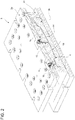
Figure 2 is a perspective view, partially sectioned and on an enlarged scale, of the tool ofFigure 1 in the assembled configuration and with parts removed for clarity; -
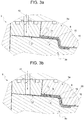
Figures 3a and 3b are section views, on an enlarged scale and with parts removed for clarity, of a detail of the tool ofFigure 2 , during two different operating conditions; and -
Figures 4a and 4b are perspective views on an enlarged scale, respectively from the bottom and from the top, of two different components of the tool ofFigure 1 , with parts removed for clarity. - With reference to
Figures 1 and2 , thenumeral 1 indicates as a whole a tool for manufacturing a composite frame for a window, or side window, of an aircraft, for example an airplane. - The
tool 1 comprises amold 3. - It should be noted that terms such as "upper", "lower", or the like that will be used in the following refer to a reference system in which the vertical direction is defined by the direction of the force of gravity, without thereby losing generality.
- The mold comprises at least: a first part, in particular an
upper part 3a, a second part, in particular alower part 3b, and a third part, in particular anintermediate part 3c, interposed, in use, between thelower part 3b and theupper part 3a. - The
parts preform 4 made of pre-impregnated material including dispersed fibers, with a predefined orientation, in a thermosetting resin matrix. - According to said preferred embodiment, the
preform 4 has a substantially annular shape and defines the base component from which the window frame will be obtained, once the manufacturing method according to the present invention has been applied. - It should be noted that the term "annular" is used in the present description and in the claims to designate any closed frame element, with a curvilinear profile (for example circular, oval, elliptical and the like), polygonal in the strict sense or polygonal in the broad sense, that is with rounded vertices.
- Preferably, the thermosetting resin is a toughened epoxy resin, for example Solvay 977 HM, or a resin with innovative properties, for example a resin added with nanofillers for conferring physical properties such as in particular a greater resistance to aging.
- The
lower part 3b comprises a shaped portion defining a peripheralannular compartment 5 configured to receive and support thepreform 4. - In the illustrated example, the
preform 4 has an "S" profiled cross section; therefore, thecompartment 5 is conveniently shaped so as to be able to receive and house said preform 4. - According to a known process not described in detail, the
preform 4 is obtained by laminating two or more layers (not illustrated) of the aforesaid material including fibers with a predefined orientation, for example carbon fibers, and by means of one or more successive consolidation steps of the aforesaid layers ("debulking") by applying vacuum. - The
preform 4 thus obtained, of the type known as "prepreg", is positioned in themold 3, in particular laid down and housed in thecompartment 5 afforded in thelower part 3a. - In particular, the prepreg thus obtained has a weight in grams comprised between 150 and 250 g/m2, preferably 190 g/m2, is impregnated at a percentage by weight of a value comprised between 35% and 45%, preferably 40%, with the thermosetting resin matrix.
- The
final preform 4 has a nominal thickness comprised between 2.40 and 2.70 mm, preferably equal to 2.58 mm. - In the case illustrated, the
preform 4 has a substantially constant thickness. - According to a possible alternative, not illustrated, the
preform 4 could also have a variable thickness; possibly this variable thickness could be obtained with localized reinforcements. - As shown in
Figure 2 , once thepreform 4 has been positioned in thecompartment 5, themold 3 is closed, so that agap 6 is defined, in use, between anupper surface 7 of thepreform 4 and aninternal surface 8 of theupper part 3a facing the upper surface 7 (figure 3a ) . - More precisely, the
upper part 3a has ashaped portion 15 in relief which reproduces and follows the "S" profile of thepreform 4 and thecompartment 5, when themold 3 is closed, that is when theparts - In particular, the
gap 6 has a substantially constant thickness, in the case illustrated comprised between 0.35 and 0.45 mm, preferably equal to 0.42 mm, and has a profile that reproduces and follows the "S" profile of thepreform 4 andcompartment 5. - Consequently, the
gap 6 extends annularly and above thepreform 4 and, therefore, thecompartment 5. - Conventional means, such as for example screws or bolts (not illustrated), are provided for positioning, closing and clamping the
various parts mold 3. - The
mold 3 comprises at least oneinlet channel 10 arranged, that is afforded, in theupper part 3a, in particular in a peripheral portion of theupper part 3a, and configured to allow the passage of fluid inside the closedmold 3. - In greater detail, the
inlet channel 10 is configured to allow the injection of thermosetting resin inside the closedmold 3, so as to fill thegap 6 and completely lap theupper surface 7 of thepreform 4. - In this regard, as shown in
Figures 1 ,2 ,3a and 3b , theinlet channel 10 comprises an inlet opening 11 through which the resin, in use, flows into theinlet channel 10 itself and then into thegap 6 through apassage 12. - In practice, in use, the resin flows from a suitable tank (not illustrated) towards the inside of the
mold 3, through theinlet channel 10; from this, the resin flows into thepassage 12 and, finally, from thepassage 12 to thegap 6. - According to an alternative embodiment not illustrated, the
mold 3 might comprise two ormore inlet channels 10; the number and the position of theinlet channels 10 depends on the geometry of the component to be treated. - As can be seen in
Figure 2 , themold 3 also comprises anoutlet channel 13, arranged, that is afforded, in theupper part 3a, in particular in a central portion of theupper part 3a, and configured to allow the passage of fluid from the inside of themold 3 towards the outside of themold 3 itself. - More precisely, the
outlet channel 13 is configured to allow the exit of the resin, previously injected, outside themold 3. - In detail, as soon as the resin has filled, in use, the
entire gap 6, it is supplied to theoutlet channel 13 and flows towards the outside of themold 3 through an outlet opening 14 (Figure 4a ) of theoutlet channel 13 itself. - In the example described, the injection of the resin takes place by sucking the resin inside the
mold 3 by applying a vacuum inside themold 3 itself. - In particular, the
tool 1 comprises a vacuum source (known per se and not illustrated) configured to be fluidly connected, in use, with theoutlet channel 13 and to apply the vacuum inside themold 3, suitably sealed, so as to cause a suction that sucks the resin through theinlet channel 10. - The application of the vacuum helps to facilitate the flow of the resin in its path inside the
mold 3 and towards theoutlet channel 13. - Alternatively, the resin injection takes place by applying a positive thrust pressure, which forces the flow of the resin from the tank towards the
inlet channel 10. - According to an alternative embodiment not illustrated, the
mold 3 could comprise two ormore outlet channels 13, where the number and the position of theoutlet channels 13 depends on the geometry of the component to be treated. - As can be seen in
Figures 1 and4b , the mold also comprises a number ofintermediate channels 16 afforded in thelower portion 3b, fluidly interposed between theinlet channel 10 and theoutlet channel 13 and configured to receive the resin in excess from thegap 6 and to supply such resin to theoutlet channel 13. - In detail, the
intermediate channels 16 are arranged so as to convey the resin from thegap 6 to a collectingportion 17 arranged upstream of theoutlet channel 13 and at the aforesaid central portion of theupper part 3a. - In greater detail, the collecting
portion 17 is arranged below theoutlet channel 13, and is facing the latter. - According to said preferred and non-limiting embodiment, the
mold 3 comprises fourintermediate channels 16 arranged (i.e. distributed) symmetrically with respect to the collectingportion 17. - More precisely, the
intermediate channels 16 are afforded in thelower portion 3b so as to form a cross with the arms mutually perpendicular and intersecting with one another at the collectingportion 17. - According to an alternative embodiment not illustrated, the intermediate channels could be arranged so as to form an X, the arms of which are transverse to each other but not orthogonal, are arranged symmetrically with respect to the collecting
portion 17 and intersect one another at the collectingportion 17. - According to a further alternative embodiment not illustrated, the
mold 3 could comprise more than fourintermediate channels 16, arranged symmetrically with respect to the collectingportion 17 so as to form an asterisk and intersect one another at the collectingportion 17. - The symmetrical arrangement of the
intermediate channels 16 allows a uniform evacuation of the resin from themold 3 and consequently favours a uniform distribution of the flow of the resin flowing from thegap 6 to theoutlet channel 13. - Preferably, the
mold 3 further comprises heating means, in particular at least one electrical resistance conveniently included in the body of themold 3, for example in theupper portion 3a, or in thelower portion 3b, or in both, and configured to be energized with current electric so as to heat themold 3 by means of Joule effect. - This heating is exploited to carry out, in use, a cure or cocure cycle of the
preform 4, after the latter has been consolidated according to the method described below. - Alternatively, the resistance can be included in the
intermediate part 3c or in any combination of theparts mold 3. - According to another possible alternative, not illustrated, the
mold 3 could be heated with hot oil or other hot fluid circulating inside suitable ducts afforded in themold 3 itself or by passive heating due to the contact of themold 3 with not represented independent hot elements. - The process for manufacturing the window frame by means of the
tool 1 according to the present invention will be described below, with particular reference to an initial condition in which thepreform 4 is positioned in thecompartment 5, themold 3 is closed (according to the method described above) and theoutlet channel 13 and, therefore, theoutlet opening 14 are open. - In this condition, the
gap 6 is well defined and delimited by thesurface 7 of thepreform 4 and by thesurface 8 of theupper part 3a. Therefore, the resin is injected inside themold 3, so as to fill thegap 6, to flow through theintermediate channels 16 and theoutlet channel 13. The verification that thegap 6 has been completely filled up by the injected resin is provided by the resin exit from theoutlet opening 13. - At this point, the
outlet channel 13 and, therefore, theoutlet opening 14 are sealed in a fluid-tight manner. At the same time, the resin continues to be injected into themold 3. - This step causes an increase in pressure inside the
mold 3, in particular inside thegap 6, and the consequent application of a uniform hydrostatic pressure by the resin (more precisely through the continuous injection of the latter) on theupper surface 7 of thepreform 4. Once the predetermined hydrostatic consolidation pressure is reached, for example 5 bar, the injection of the resin is stopped. In this condition, the resin does not further impregnate thepreform 4, but merely laps theupper surface 7 thereof, applying the aforesaid hydrostatic pressure. - In practice, the step for applying the hydrostatic pressure is carried out by opening the
outlet 14 which is sealed at the same time when the heat is applied, for example by means of the systems described above. - Thus, a cure or cocure cycle of the
preform 4 in themold 3 is carried out together with the injected resin present inside themold 3 itself so as to achieve the consolidation of the material constituting the finished window frame. - After completing said cure or cocure cycle and an appropriate cooling cycle, carried out always by maintaining the consolidation hydrostatic pressure, the
mold 3 is opened, i.e. theupper part 3a is separated from thelower part 3b, and thepreform 4 is extracted from themold 3 itself. - It should be noted that, at the end of the process, the
layer 20 of thermosetting resin which fills thegap 6 and which is arranged in contact with theupper surface 7 remains in contact with thepreform 4, becoming an integral part thereof, even after the extraction of thepreform 4 itself, without however impregnating it. - The window frame, formed by the
preform 4 made of pre-impregnated fibrous material and consolidated by hydrostatic pressure, and comprising thelayer 20 of resin injected and consolidated on thesurface 7, is thus obtained. - From an examination of the features of the method and of the
tool 1 for manufacturing the aircraft window frame made according to the present invention, the advantages that it allows to obtain are evident. - In particular, the window frame obtained by the method and the tool according to the present invention maintains the orientation of the fibers of the
preform 4, which, as specified above, are not impregnated in an uncontrolled manner during the injection of resin into themold 3. This allows to guarantee the direction of the fibers of thepreform 4. - Furthermore, the method described above allows to obtain frames with low levels of surface porosity and high aesthetic finish.
- In addition, the window frames thus obtained do not require further processing.
- It is clear that modifications and variations may be made to the method and to the
tool 1 described and illustrated here without thereby departing from the scope of protection defined by the claims.
Claims (9)
- Method for manufacturing a composite aircraft window frame; the method comprising the steps of:a) positioning in a mold (3) a preform (4) made of pre-impregnated material including dispersed fibers, with a predefined orientation, in a thermosetting resin matrix;b) closing the mold (3) so as to define a gap (6) between at least one surface (7) of said preform (4) and a portion (15) of said mold (3);c) injecting thermosetting resin into the closed mold (3) through an inlet opening (11) of the mold (3) itself, so as to fill said gap (6) and completely lap said surface (7) of the preform (4); andd) applying a uniform hydrostatic pressure on said surface (7) by the injection of said resin.
- The method as claimed in claim 1, wherein the step d) comprises the steps of:e) sealing the mold (3) in a fluid-tight manner, with the exception of said inlet opening (11); andf) continuing to inject the resin through said inlet opening (11).
- The method as claimed in claim 2, wherein the mold (3) comprises an outlet opening (14) through which the resin exits, in use, from the mold (3) itself; and in which the step c) is carried out with the outlet opening (14) opened and the step d) is carried out with the outlet opening (14) sealed.
- The method as claimed in any one of the foregoing claims, wherein, in steps c) and d), the thermosetting resin is injected onto said surface (7), without impregnating the preform (4).
- The method as claimed in any one of the foregoing claims, wherein, in step c), the resin is sucked inside the mold (3) by applying vacuum.
- The method as claimed in any one of the foregoing claims, further comprising the step of supplying heat to the material present in said mold (3) during the step d) so as to carry out a cure or cocure cycle at least of the preform (4).
- A tool (1) for manufacturing a composite aircraft window frame starting from a preform (4) made of pre-impregnated material including dispersed fibers, with predefined orientation, in a thermosetting resin matrix;
said tool (1) comprising a mold (3) apt to house said preform (4) and configured to be closed around said preform (4) so that a gap (6) is defined, in use, between a surface (7) of said preform (4) and an inner surface (8) of said mold (3);
said mold (3) comprising at least one inlet channel (10), configured to allow the injection of thermosetting resin into the closed mold (3), so as to completely lap said surface (7) of said preform (4), to fill said gap (6) and to apply a uniform hydrostatic pressure on said surface (7) of said preform (4), and at least one outlet channel (13), configured to allow the exit of thermosetting resin from said mold (3);
wherein said mold (3) further comprises intermediate channels (16) fluidly interposed between said inlet channel (10) and said outlet channel (13) and configured to receive the resin in excess from said gap (6) and to supply such resin to said output channel (13) ;
said intermediate channels (16) being arranged so as to convey the resin to a collecting portion (17) arranged upstream of said outlet channel (13) relative to a direction of flow of the resin from the inlet channel (10) to the outlet channel (13);
said intermediate channels (16) being arranged symmetrically with respect to said collecting portion (17) . - The tool as claimed in claim 7, wherein said intermediate channels (16) are arranged so as to form a cross or an asterisk, intersecting with one another at said collecting portion (17).
- The tool as claimed in claim 7 or 8, further comprising at least one electric resistance arranged in correspondence of said mold (3) and configured to be energized with electric current so as to heat the mold (3) by means of Joule effect.
Applications Claiming Priority (1)
| Application Number | Priority Date | Filing Date | Title |
|---|---|---|---|
| IT102019000017420A IT201900017420A1 (en) | 2019-09-27 | 2019-09-27 | METHOD AND TOOL FOR MANUFACTURING A COMPOSITE MATERIAL FRAME OF AN AIRCRAFT WINDOW |
Publications (2)
| Publication Number | Publication Date |
|---|---|
| EP3797963A1 true EP3797963A1 (en) | 2021-03-31 |
| EP3797963B1 EP3797963B1 (en) | 2022-08-17 |
Family
ID=69375865
Family Applications (1)
| Application Number | Title | Priority Date | Filing Date |
|---|---|---|---|
| EP20198195.8A Active EP3797963B1 (en) | 2019-09-27 | 2020-09-24 | Method and tool for manufacturing a composite aircraft window frame |
Country Status (8)
| Country | Link |
|---|---|
| US (1) | US11498291B2 (en) |
| EP (1) | EP3797963B1 (en) |
| JP (1) | JP7621761B2 (en) |
| CN (1) | CN112571833A (en) |
| CA (1) | CA3094278A1 (en) |
| ES (1) | ES2929562T3 (en) |
| IT (1) | IT201900017420A1 (en) |
| PL (1) | PL3797963T3 (en) |
Cited By (1)
| Publication number | Priority date | Publication date | Assignee | Title |
|---|---|---|---|---|
| US12257788B2 (en) | 2022-10-31 | 2025-03-25 | GM Global Technology Operations LLC | Preform with variable fiber density, forming and molding tool and method for forming of composite materials |
Families Citing this family (6)
| Publication number | Priority date | Publication date | Assignee | Title |
|---|---|---|---|---|
| DE102021117594B4 (en) | 2021-07-07 | 2023-05-17 | Deutsches Zentrum für Luft- und Raumfahrt e.V. | Outer paneling for flying objects and method for the production thereof |
| CN113263664B (en) * | 2021-07-20 | 2021-11-09 | 常州市新创智能科技有限公司 | Window frame curing forming die and method |
| CN114872342B (en) * | 2022-04-29 | 2023-01-31 | 常州市新创智能科技有限公司 | Novel fabric preforming method for inner buckling part and preparation mold thereof |
| CN115384079B (en) * | 2022-07-29 | 2024-09-20 | 北京卫星制造厂有限公司 | Rigid material cladding composite type compression molding tool and method |
| CN118082252A (en) * | 2024-03-13 | 2024-05-28 | 上海中船船舶设计技术国家工程研究中心有限公司 | A method for manufacturing a high-speed boat driving platform |
| WO2025203873A1 (en) * | 2024-03-29 | 2025-10-02 | 川崎重工業株式会社 | Window frame manufacturing method and aircraft window frame |
Citations (3)
| Publication number | Priority date | Publication date | Assignee | Title |
|---|---|---|---|---|
| EP0332899A2 (en) * | 1988-03-14 | 1989-09-20 | AlliedSignal Inc. | Injection molding of fabric-reinforced elastomeric diaphragm |
| DE102012110307A1 (en) * | 2012-10-29 | 2014-04-30 | Kraussmaffei Technologies Gmbh | Process for the production of composite plastic components by high pressure resin transfer presses and associated high pressure resin transfer press tool |
| US20160176085A1 (en) * | 2014-12-19 | 2016-06-23 | Airbus Operations Gmbh | Method and system for producing composite structures |
Family Cites Families (9)
| Publication number | Priority date | Publication date | Assignee | Title |
|---|---|---|---|---|
| US5023041A (en) * | 1987-12-10 | 1991-06-11 | General Electric Company | Method for making a fiber reinforced composite article |
| US6406659B1 (en) * | 1995-03-28 | 2002-06-18 | Eric Lang | Composite molding method and apparatus |
| DE10106923A1 (en) * | 2001-02-15 | 2002-09-19 | Bpw Bergische Achsen Kg | Process for the production of components made of fiber-reinforced plastic |
| EP2565019A1 (en) * | 2004-02-17 | 2013-03-06 | Toray Industries, Inc. | RTM molding method |
| US20070063393A1 (en) * | 2005-09-22 | 2007-03-22 | Nicolas Vernin | Vacuum assisted resin transfer molding techniques with flow flooding chamber |
| ITTO20070796A1 (en) * | 2007-11-08 | 2009-05-09 | Alenia Aeronautica Spa | EQUIPMENT FOR RESIN INFUSION IN A CLOSED MOLD PREFORM. |
| US8574484B2 (en) * | 2009-01-29 | 2013-11-05 | Toray Industries, Inc. | RTM method and method for manufacturing fiber-reinforced resin molded body |
| JP5693296B2 (en) * | 2011-02-28 | 2015-04-01 | 三菱重工業株式会社 | RTM molding device, RTM molding method, and semi-molded body |
| MX2016001158A (en) * | 2013-07-26 | 2016-04-29 | Magna Int Inc | Mould arrangement and method for compression moulding fiber reinforced preforms. |
-
2019
- 2019-09-27 IT IT102019000017420A patent/IT201900017420A1/en unknown
-
2020
- 2020-09-16 JP JP2020155771A patent/JP7621761B2/en active Active
- 2020-09-22 CN CN202011001473.5A patent/CN112571833A/en active Pending
- 2020-09-24 US US17/030,920 patent/US11498291B2/en active Active
- 2020-09-24 PL PL20198195.8T patent/PL3797963T3/en unknown
- 2020-09-24 ES ES20198195T patent/ES2929562T3/en active Active
- 2020-09-24 CA CA3094278A patent/CA3094278A1/en active Pending
- 2020-09-24 EP EP20198195.8A patent/EP3797963B1/en active Active
Patent Citations (3)
| Publication number | Priority date | Publication date | Assignee | Title |
|---|---|---|---|---|
| EP0332899A2 (en) * | 1988-03-14 | 1989-09-20 | AlliedSignal Inc. | Injection molding of fabric-reinforced elastomeric diaphragm |
| DE102012110307A1 (en) * | 2012-10-29 | 2014-04-30 | Kraussmaffei Technologies Gmbh | Process for the production of composite plastic components by high pressure resin transfer presses and associated high pressure resin transfer press tool |
| US20160176085A1 (en) * | 2014-12-19 | 2016-06-23 | Airbus Operations Gmbh | Method and system for producing composite structures |
Cited By (1)
| Publication number | Priority date | Publication date | Assignee | Title |
|---|---|---|---|---|
| US12257788B2 (en) | 2022-10-31 | 2025-03-25 | GM Global Technology Operations LLC | Preform with variable fiber density, forming and molding tool and method for forming of composite materials |
Also Published As
| Publication number | Publication date |
|---|---|
| JP7621761B2 (en) | 2025-01-27 |
| EP3797963B1 (en) | 2022-08-17 |
| CA3094278A1 (en) | 2021-03-27 |
| RU2020131488A (en) | 2022-03-24 |
| ES2929562T3 (en) | 2022-11-30 |
| IT201900017420A1 (en) | 2021-03-27 |
| BR102020019263A2 (en) | 2021-04-20 |
| PL3797963T3 (en) | 2022-12-27 |
| US11498291B2 (en) | 2022-11-15 |
| JP2021054398A (en) | 2021-04-08 |
| US20210094248A1 (en) | 2021-04-01 |
| CN112571833A (en) | 2021-03-30 |
Similar Documents
| Publication | Publication Date | Title |
|---|---|---|
| EP3797963B1 (en) | Method and tool for manufacturing a composite aircraft window frame | |
| US6861017B1 (en) | Method for forming composite parts from volatile-emitting materials using breathable tooling | |
| CN110077015B (en) | Fillet filler and method for manufacturing fillet filler and composite structure | |
| EP3533594B1 (en) | Method of making composite structures having intergrated stiffeners with smooth runouts | |
| EP2953786B1 (en) | Method and apparatus for reworking structures | |
| CN101743117B (en) | Molds and methods for manufacturing aircraft frames from composite materials | |
| CA2975572C (en) | Apparatus and method for forming fibre reinforced composite structures | |
| CN111936303A (en) | Method of manufacturing a blade with an assembled metal leading edge for a gas turbine engine from a composite material | |
| EP2736707A2 (en) | Methods and systems for forming reinforced composite articles having variable thickness corners | |
| US20150137430A1 (en) | Over-molded vacuum barrier and inner mold line bag carrier with soluble details in trapped closed mold tooling | |
| CN102470613A (en) | Laminated composite material rod, fabrication method and use in composite material structure | |
| EP2481558B1 (en) | Method for manufacturing of preimpregnated preform | |
| CN106739004A (en) | The preparation method and gained Special-shaped I beam of carbon fibre composite Special-shaped I beam | |
| JP2022510269A (en) | Wind turbine mold B surface heating and cooling method using a vacuum bag with a fluid channel | |
| EP2983899B1 (en) | Multi-component composite structures | |
| CA2836015C (en) | Resin transfer molding method and resin transfer molding apparatus | |
| RU2819190C2 (en) | Method and tooling for making composite frame of aircraft window | |
| BR102020019263B1 (en) | METHOD FOR FABRICATING A COMPOSITE AIRCRAFT WINDOW FRAME, AND TOOL | |
| EP4520503A1 (en) | Thermoplastic composite components and method for forming same | |
| HK1158139A (en) | Composite structure and method of making same |
Legal Events
| Date | Code | Title | Description |
|---|---|---|---|
| PUAI | Public reference made under article 153(3) epc to a published international application that has entered the european phase |
Free format text: ORIGINAL CODE: 0009012 |
|
| STAA | Information on the status of an ep patent application or granted ep patent |
Free format text: STATUS: THE APPLICATION HAS BEEN PUBLISHED |
|
| STAA | Information on the status of an ep patent application or granted ep patent |
Free format text: STATUS: REQUEST FOR EXAMINATION WAS MADE |
|
| AK | Designated contracting states |
Kind code of ref document: A1 Designated state(s): AL AT BE BG CH CY CZ DE DK EE ES FI FR GB GR HR HU IE IS IT LI LT LU LV MC MK MT NL NO PL PT RO RS SE SI SK SM TR |
|
| AX | Request for extension of the european patent |
Extension state: BA ME |
|
| 17P | Request for examination filed |
Effective date: 20210316 |
|
| RBV | Designated contracting states (corrected) |
Designated state(s): AL AT BE BG CH CY CZ DE DK EE ES FI FR GB GR HR HU IE IS IT LI LT LU LV MC MK MT NL NO PL PT RO RS SE SI SK SM TR |
|
| GRAP | Despatch of communication of intention to grant a patent |
Free format text: ORIGINAL CODE: EPIDOSNIGR1 |
|
| STAA | Information on the status of an ep patent application or granted ep patent |
Free format text: STATUS: GRANT OF PATENT IS INTENDED |
|
| RIC1 | Information provided on ipc code assigned before grant |
Ipc: B29L 31/30 20060101ALN20220216BHEP Ipc: B29K 105/08 20060101ALN20220216BHEP Ipc: B29L 31/00 20060101ALN20220216BHEP Ipc: B29K 101/10 20060101ALN20220216BHEP Ipc: B64C 1/14 20060101ALI20220216BHEP Ipc: B29C 33/00 20060101ALI20220216BHEP Ipc: B29C 45/14 20060101AFI20220216BHEP |
|
| INTG | Intention to grant announced |
Effective date: 20220310 |
|
| GRAS | Grant fee paid |
Free format text: ORIGINAL CODE: EPIDOSNIGR3 |
|
| GRAA | (expected) grant |
Free format text: ORIGINAL CODE: 0009210 |
|
| STAA | Information on the status of an ep patent application or granted ep patent |
Free format text: STATUS: THE PATENT HAS BEEN GRANTED |
|
| AK | Designated contracting states |
Kind code of ref document: B1 Designated state(s): AL AT BE BG CH CY CZ DE DK EE ES FI FR GB GR HR HU IE IS IT LI LT LU LV MC MK MT NL NO PL PT RO RS SE SI SK SM TR |
|
| REG | Reference to a national code |
Ref country code: CH Ref legal event code: EP |
|
| REG | Reference to a national code |
Ref country code: DE Ref legal event code: R096 Ref document number: 602020004562 Country of ref document: DE |
|
| REG | Reference to a national code |
Ref country code: IE Ref legal event code: FG4D |
|
| REG | Reference to a national code |
Ref country code: AT Ref legal event code: REF Ref document number: 1511899 Country of ref document: AT Kind code of ref document: T Effective date: 20220915 |
|
| REG | Reference to a national code |
Ref country code: RO Ref legal event code: EPE Ref country code: SE Ref legal event code: TRGR |
|
| REG | Reference to a national code |
Ref country code: NL Ref legal event code: FP |
|
| REG | Reference to a national code |
Ref country code: ES Ref legal event code: FG2A Ref document number: 2929562 Country of ref document: ES Kind code of ref document: T3 Effective date: 20221130 |
|
| REG | Reference to a national code |
Ref country code: NO Ref legal event code: T2 Effective date: 20220817 |
|
| REG | Reference to a national code |
Ref country code: LT Ref legal event code: MG9D |
|
| PG25 | Lapsed in a contracting state [announced via postgrant information from national office to epo] |
Ref country code: RS Free format text: LAPSE BECAUSE OF FAILURE TO SUBMIT A TRANSLATION OF THE DESCRIPTION OR TO PAY THE FEE WITHIN THE PRESCRIBED TIME-LIMIT Effective date: 20220817 Ref country code: PT Free format text: LAPSE BECAUSE OF FAILURE TO SUBMIT A TRANSLATION OF THE DESCRIPTION OR TO PAY THE FEE WITHIN THE PRESCRIBED TIME-LIMIT Effective date: 20221219 Ref country code: LV Free format text: LAPSE BECAUSE OF FAILURE TO SUBMIT A TRANSLATION OF THE DESCRIPTION OR TO PAY THE FEE WITHIN THE PRESCRIBED TIME-LIMIT Effective date: 20220817 Ref country code: LT Free format text: LAPSE BECAUSE OF FAILURE TO SUBMIT A TRANSLATION OF THE DESCRIPTION OR TO PAY THE FEE WITHIN THE PRESCRIBED TIME-LIMIT Effective date: 20220817 Ref country code: FI Free format text: LAPSE BECAUSE OF FAILURE TO SUBMIT A TRANSLATION OF THE DESCRIPTION OR TO PAY THE FEE WITHIN THE PRESCRIBED TIME-LIMIT Effective date: 20220817 |
|
| PG25 | Lapsed in a contracting state [announced via postgrant information from national office to epo] |
Ref country code: IS Free format text: LAPSE BECAUSE OF FAILURE TO SUBMIT A TRANSLATION OF THE DESCRIPTION OR TO PAY THE FEE WITHIN THE PRESCRIBED TIME-LIMIT Effective date: 20221217 Ref country code: HR Free format text: LAPSE BECAUSE OF FAILURE TO SUBMIT A TRANSLATION OF THE DESCRIPTION OR TO PAY THE FEE WITHIN THE PRESCRIBED TIME-LIMIT Effective date: 20220817 Ref country code: GR Free format text: LAPSE BECAUSE OF FAILURE TO SUBMIT A TRANSLATION OF THE DESCRIPTION OR TO PAY THE FEE WITHIN THE PRESCRIBED TIME-LIMIT Effective date: 20221118 |
|
| PG25 | Lapsed in a contracting state [announced via postgrant information from national office to epo] |
Ref country code: SM Free format text: LAPSE BECAUSE OF FAILURE TO SUBMIT A TRANSLATION OF THE DESCRIPTION OR TO PAY THE FEE WITHIN THE PRESCRIBED TIME-LIMIT Effective date: 20220817 Ref country code: DK Free format text: LAPSE BECAUSE OF FAILURE TO SUBMIT A TRANSLATION OF THE DESCRIPTION OR TO PAY THE FEE WITHIN THE PRESCRIBED TIME-LIMIT Effective date: 20220817 Ref country code: CZ Free format text: LAPSE BECAUSE OF FAILURE TO SUBMIT A TRANSLATION OF THE DESCRIPTION OR TO PAY THE FEE WITHIN THE PRESCRIBED TIME-LIMIT Effective date: 20220817 |
|
| REG | Reference to a national code |
Ref country code: DE Ref legal event code: R097 Ref document number: 602020004562 Country of ref document: DE |
|
| REG | Reference to a national code |
Ref country code: BE Ref legal event code: MM Effective date: 20220930 |
|
| PG25 | Lapsed in a contracting state [announced via postgrant information from national office to epo] |
Ref country code: SK Free format text: LAPSE BECAUSE OF FAILURE TO SUBMIT A TRANSLATION OF THE DESCRIPTION OR TO PAY THE FEE WITHIN THE PRESCRIBED TIME-LIMIT Effective date: 20220817 Ref country code: MC Free format text: LAPSE BECAUSE OF FAILURE TO SUBMIT A TRANSLATION OF THE DESCRIPTION OR TO PAY THE FEE WITHIN THE PRESCRIBED TIME-LIMIT Effective date: 20220817 Ref country code: EE Free format text: LAPSE BECAUSE OF FAILURE TO SUBMIT A TRANSLATION OF THE DESCRIPTION OR TO PAY THE FEE WITHIN THE PRESCRIBED TIME-LIMIT Effective date: 20220817 |
|
| PLBE | No opposition filed within time limit |
Free format text: ORIGINAL CODE: 0009261 |
|
| STAA | Information on the status of an ep patent application or granted ep patent |
Free format text: STATUS: NO OPPOSITION FILED WITHIN TIME LIMIT |
|
| PG25 | Lapsed in a contracting state [announced via postgrant information from national office to epo] |
Ref country code: LU Free format text: LAPSE BECAUSE OF NON-PAYMENT OF DUE FEES Effective date: 20220924 Ref country code: AL Free format text: LAPSE BECAUSE OF FAILURE TO SUBMIT A TRANSLATION OF THE DESCRIPTION OR TO PAY THE FEE WITHIN THE PRESCRIBED TIME-LIMIT Effective date: 20220817 |
|
| 26N | No opposition filed |
Effective date: 20230519 |
|
| REG | Reference to a national code |
Ref country code: AT Ref legal event code: UEP Ref document number: 1511899 Country of ref document: AT Kind code of ref document: T Effective date: 20220817 |
|
| PG25 | Lapsed in a contracting state [announced via postgrant information from national office to epo] |
Ref country code: SI Free format text: LAPSE BECAUSE OF FAILURE TO SUBMIT A TRANSLATION OF THE DESCRIPTION OR TO PAY THE FEE WITHIN THE PRESCRIBED TIME-LIMIT Effective date: 20220817 |
|
| PG25 | Lapsed in a contracting state [announced via postgrant information from national office to epo] |
Ref country code: BE Free format text: LAPSE BECAUSE OF NON-PAYMENT OF DUE FEES Effective date: 20220930 |
|
| PG25 | Lapsed in a contracting state [announced via postgrant information from national office to epo] |
Ref country code: CY Free format text: LAPSE BECAUSE OF FAILURE TO SUBMIT A TRANSLATION OF THE DESCRIPTION OR TO PAY THE FEE WITHIN THE PRESCRIBED TIME-LIMIT Effective date: 20220817 |
|
| PG25 | Lapsed in a contracting state [announced via postgrant information from national office to epo] |
Ref country code: MK Free format text: LAPSE BECAUSE OF FAILURE TO SUBMIT A TRANSLATION OF THE DESCRIPTION OR TO PAY THE FEE WITHIN THE PRESCRIBED TIME-LIMIT Effective date: 20220817 |
|
| PG25 | Lapsed in a contracting state [announced via postgrant information from national office to epo] |
Ref country code: HU Free format text: LAPSE BECAUSE OF FAILURE TO SUBMIT A TRANSLATION OF THE DESCRIPTION OR TO PAY THE FEE WITHIN THE PRESCRIBED TIME-LIMIT; INVALID AB INITIO Effective date: 20200924 Ref country code: BG Free format text: LAPSE BECAUSE OF FAILURE TO SUBMIT A TRANSLATION OF THE DESCRIPTION OR TO PAY THE FEE WITHIN THE PRESCRIBED TIME-LIMIT Effective date: 20220817 |
|
| PG25 | Lapsed in a contracting state [announced via postgrant information from national office to epo] |
Ref country code: MT Free format text: LAPSE BECAUSE OF FAILURE TO SUBMIT A TRANSLATION OF THE DESCRIPTION OR TO PAY THE FEE WITHIN THE PRESCRIBED TIME-LIMIT Effective date: 20220817 |
|
| REG | Reference to a national code |
Ref country code: CH Ref legal event code: U11 Free format text: ST27 STATUS EVENT CODE: U-0-0-U10-U11 (AS PROVIDED BY THE NATIONAL OFFICE) Effective date: 20251001 |
|
| PGFP | Annual fee paid to national office [announced via postgrant information from national office to epo] |
Ref country code: DE Payment date: 20250926 Year of fee payment: 6 |
|
| PGFP | Annual fee paid to national office [announced via postgrant information from national office to epo] |
Ref country code: NO Payment date: 20250917 Year of fee payment: 6 |
|
| PGFP | Annual fee paid to national office [announced via postgrant information from national office to epo] |
Ref country code: TR Payment date: 20250904 Year of fee payment: 6 Ref country code: PL Payment date: 20250916 Year of fee payment: 6 Ref country code: NL Payment date: 20250925 Year of fee payment: 6 Ref country code: IT Payment date: 20250903 Year of fee payment: 6 |
|
| PGFP | Annual fee paid to national office [announced via postgrant information from national office to epo] |
Ref country code: GB Payment date: 20250923 Year of fee payment: 6 |
|
| PGFP | Annual fee paid to national office [announced via postgrant information from national office to epo] |
Ref country code: FR Payment date: 20250925 Year of fee payment: 6 Ref country code: AT Payment date: 20250917 Year of fee payment: 6 |
|
| PGFP | Annual fee paid to national office [announced via postgrant information from national office to epo] |
Ref country code: SE Payment date: 20250924 Year of fee payment: 6 |
|
| PGFP | Annual fee paid to national office [announced via postgrant information from national office to epo] |
Ref country code: IE Payment date: 20250917 Year of fee payment: 6 |
|
| PGFP | Annual fee paid to national office [announced via postgrant information from national office to epo] |
Ref country code: RO Payment date: 20250909 Year of fee payment: 6 |
|
| PGFP | Annual fee paid to national office [announced via postgrant information from national office to epo] |
Ref country code: CH Payment date: 20251001 Year of fee payment: 6 |
|
| PGFP | Annual fee paid to national office [announced via postgrant information from national office to epo] |
Ref country code: ES Payment date: 20251015 Year of fee payment: 6 |