EP3797947A1 - Razor cartridge - Google Patents
Razor cartridge Download PDFInfo
- Publication number
- EP3797947A1 EP3797947A1 EP19199652.9A EP19199652A EP3797947A1 EP 3797947 A1 EP3797947 A1 EP 3797947A1 EP 19199652 A EP19199652 A EP 19199652A EP 3797947 A1 EP3797947 A1 EP 3797947A1
- Authority
- EP
- European Patent Office
- Prior art keywords
- cutting member
- longitudinal
- cutting
- razor cartridge
- cartridge
- Prior art date
- Legal status (The legal status is an assumption and is not a legal conclusion. Google has not performed a legal analysis and makes no representation as to the accuracy of the status listed.)
- Granted
Links
Images





Classifications
-
- B—PERFORMING OPERATIONS; TRANSPORTING
- B26—HAND CUTTING TOOLS; CUTTING; SEVERING
- B26B—HAND-HELD CUTTING TOOLS NOT OTHERWISE PROVIDED FOR
- B26B21/00—Razors of the open or knife type; Safety razors or other shaving implements of the planing type; Hair-trimming devices involving a razor-blade; Equipment therefor
- B26B21/40—Details or accessories
- B26B21/4012—Housing details, e.g. for cartridges
- B26B21/4031—Housing details, e.g. for cartridges characterised by special geometric shaving parameters, e.g. blade span or exposure
-
- A—HUMAN NECESSITIES
- A45—HAND OR TRAVELLING ARTICLES
- A45D—HAIRDRESSING OR SHAVING EQUIPMENT; EQUIPMENT FOR COSMETICS OR COSMETIC TREATMENTS, e.g. FOR MANICURING OR PEDICURING
- A45D27/00—Shaving accessories
- A45D27/22—Containers or carriers for storing shaving appliances
- A45D27/24—Containers or carriers for storing shaving appliances for storing thin flat razor blades, e.g. after use
-
- B—PERFORMING OPERATIONS; TRANSPORTING
- B26—HAND CUTTING TOOLS; CUTTING; SEVERING
- B26B—HAND-HELD CUTTING TOOLS NOT OTHERWISE PROVIDED FOR
- B26B21/00—Razors of the open or knife type; Safety razors or other shaving implements of the planing type; Hair-trimming devices involving a razor-blade; Equipment therefor
- B26B21/40—Details or accessories
- B26B21/4012—Housing details, e.g. for cartridges
-
- B—PERFORMING OPERATIONS; TRANSPORTING
- B26—HAND CUTTING TOOLS; CUTTING; SEVERING
- B26B—HAND-HELD CUTTING TOOLS NOT OTHERWISE PROVIDED FOR
- B26B21/00—Razors of the open or knife type; Safety razors or other shaving implements of the planing type; Hair-trimming devices involving a razor-blade; Equipment therefor
- B26B21/40—Details or accessories
- B26B21/4068—Mounting devices; Manufacture of razors or cartridges
-
- B—PERFORMING OPERATIONS; TRANSPORTING
- B26—HAND CUTTING TOOLS; CUTTING; SEVERING
- B26B—HAND-HELD CUTTING TOOLS NOT OTHERWISE PROVIDED FOR
- B26B21/00—Razors of the open or knife type; Safety razors or other shaving implements of the planing type; Hair-trimming devices involving a razor-blade; Equipment therefor
- B26B21/02—Razors of the open or knife type; Safety razors or other shaving implements of the planing type; Hair-trimming devices involving a razor-blade; Equipment therefor involving unchangeable blades
- B26B21/06—Safety razors with fixed blade, e.g. with moulded-in blade
-
- B—PERFORMING OPERATIONS; TRANSPORTING
- B26—HAND CUTTING TOOLS; CUTTING; SEVERING
- B26B—HAND-HELD CUTTING TOOLS NOT OTHERWISE PROVIDED FOR
- B26B21/00—Razors of the open or knife type; Safety razors or other shaving implements of the planing type; Hair-trimming devices involving a razor-blade; Equipment therefor
- B26B21/08—Razors of the open or knife type; Safety razors or other shaving implements of the planing type; Hair-trimming devices involving a razor-blade; Equipment therefor involving changeable blades
- B26B21/14—Safety razors with one or more blades arranged transversely to the handle
- B26B21/22—Safety razors with one or more blades arranged transversely to the handle involving several blades to be used simultaneously
- B26B21/222—Safety razors with one or more blades arranged transversely to the handle involving several blades to be used simultaneously with the blades moulded into, or attached to, a changeable unit
- B26B21/227—Safety razors with one or more blades arranged transversely to the handle involving several blades to be used simultaneously with the blades moulded into, or attached to, a changeable unit with blades being resiliently mounted in the changeable unit
Definitions
- the aspects described in the following disclosure relate to a razor cartridge, a method for manufacturing a razor cartridge, a shaving razor assembly and an associated kit of parts.
- Razor cartridges are permanently or removably attached to a razor handle that, in use, is oriented in shaving direction.
- Razor cartridges typically comprise one or more cutting members, each supporting a blade, mounted perpendicular to the shaving direction.
- Razor cartridges are also typically provided with a guard (at a leading longitudinal side of the razor cartridge in the shaving direction) and a cap (at a trailing longitudinal side of the razor cartridge in the shaving direction). In use, a user holds the razor handle in the shaving direction and brings the razor cartridge into contact with a portion of skin defining a shaving plane.
- the shaving plane is defined as the tangential line intersecting the first and second skin contact points of, for example, cutting edges of the shaving head. More simply, the shaving plane may be approximated as a line between the highest points on the skin-contacting surfaced of a razor cartridge - for example, the flat plane between the top of a guard and the top of a cap of the shaving head. Movement of the razor handle causes the blades of the razor cartridge to be moved across the shaving plane in the shaving direction, enabling the blades to remove unwanted hair.
- the performance of razor cartridges may be further improved.
- a razor cartridge comprising a frame.
- the frame comprises a leading longitudinal member and a trailing longitudinal member defining a cartridge plane, and at least one transverse frame member disposed in between, and joining, the leading longitudinal member and the trailing longitudinal member, in a transverse direction of the razor cartridge.
- the at least one transverse frame member comprises a plurality of cutting member guides defining a plurality of cutting member support slots, each cutting member support slot configured to accommodate a longitudinal cutting member.
- the razor cartridge further comprises a plurality of longitudinal cutting members, wherein each cutting member is disposed in a respective cutting member support slot.
- At least one cutting member guide comprises a first planar face proximate to a first cutting member support slot.
- the at least one cutting member guide further comprises an intermediate portion that is a greater distance away from the first cutting member support slot than the first planar face in the transverse direction of the razor cartridge.
- a first longitudinal distance is defined by the width of the first planar face of the at least one cutting member guide in the cartridge plane, and a second longitudinal distance is defined by width of the intermediate portion of the first cutting member guide at the widest point of the first cutting member guide in the cartridge plane.
- a ratio of the first longitudinal distance and the second longitudinal distance is in the range 0.1 : 0.8.
- a method for manufacturing a razor cartridge comprises:
- a shaving razor assembly comprising: a razor handle, and a razor cartridge according to the first aspect.
- the razor cartridge is either releasably attached to the razor handle, integrally formed with the razor handle via a non-pivotable connection, or integrally formed with the razor handle via a pivotable connection.
- a kit of parts comprising a razor cartridge holder comprising a plurality of razor cartridges according to the first aspect.
- the cutting members (blades) of a razor cartridge are supported by cutting member guides that are strengthened owing to their shape.
- the cutting member guides can better resist deflection when a force is applied to them by a cutting member support during shaving, for example. Undesired movement of the cutting members during shaving is therefore significantly reduced.
- the stability of the cutting member guides designed according to the technique discussed herein enables the provision of an open architecture shaver head that facilitates the rinsing and cleansing of debris from the shaver head during shaving.
- cutting member means a component of a razor cartridge that, in use, contacts the skin of a user and cuts protruding hairs.
- a cutting member can mean at least a razor blade having a blade with a cutting edge glued, or laser welded, to a separate bent support member.
- the bent support member is fitted into a cutting member support slot in-between two opposed cutting member guides, such as protrusions from a transverse frame member of the razor cartridge.
- the blade can be attached to the face of the bent support member that faces towards a user of the razor cartridge, in use.
- the blade can be attached to the face of the bent support member that faces away from a user of the razor cartridge, in use.
- each cutting member has two contact points with the skin of the user (the blade edge, and the distal end of the bent support member), to thus reduce pressure on the user's skin.
- the cutting member may be a "bent blade". This is an integrally formed cutting member comprising a radiused bend, and a cutting edge formed at a distal end of the radiused bend.
- a “group of cutting members” may consist of the same type of cutting members, or may comprise at least one bent blade, or another type of blade for example.
- the term “cartridge plane” means a plane passing through the joint of one or more protuberances forming cutting member guides with a transverse frame member of the razor cartridge upon which the protuberances are formed.
- the cartridge plane is substantially parallel to a shaving plane of the razor cartridge, but the cartridge plane is further away from the shaving plane because it is aligned with the surface nearest to the shaving plane of the transverse frame members of a razor cartridge upon which the protuberances forming the cutting member supports are formed.
- leading means the side of the razor cartridge that contacts a portion of a user's skin first, in normal use.
- the term “trailing” means the side of the razor cartridge that contacts a portion of a user's skin last, in normal use.
- FIG 1 is a perspective view of a shaving razor assembly 1 according to an aspect.
- the shaving razor assembly comprises cutting members which are not driven by a motor.
- the shaving razor assembly 1 comprises a handle 2 extending in a handle direction H between a proximal portion 4 and a distal portion 6 of the handle 2.
- a razor cartridge 20 is mounted at the distal portion 6 of the handle 2. The razor cartridge 20 will be discussed in more detail following discussion of the shaving razor assembly 1.
- the mounting of the razor cartridge 20 to the distal portion 6 of the handle 2 in the illustration is, in an embodiment, via a pivotable bearing member 8, enabling a frame of reference of the handle 2 to vary relative to a frame of reference of the razor cartridge 20. This enables the angle of the razor cartridge against the skin of a user to vary and adapt to changes during use.
- the razor cartridge 20 pivots relative to the handle 2 about the longitudinal axis L of the razor cartridge 20, in use.
- the pivoting enables the user to adapt to contours of the body, for example.
- the longitudinal axis L of the razor cartridge 20 is substantially perpendicular to the shaving direction along the handle 2.
- Another example of a connection mechanism for connecting the razor cartridge 20 to the handle 2 is discussed in WO2006/027018 A1 .
- Another example is a razor cartridge 20 that may pivot relative to a second pivot axis (a rocking axis), substantially perpendicular to axis L.
- the pivotable bearing member 8 may be omitted (not illustrated) and the handle 2 provided as an integrally connected part of the support of the razor cartridge 20.
- the pivotable bearing member 8 may further comprise, or be replaced by, a release mechanism 5a, 5b, enabling rapid release of an exhausted razor cartridge from the handle 2.
- the handle 2 and the support of the razor cartridge 20 are integrally formed with a pivotable bearing member (not illustrated) such as a resilient plastic spring member.
- the handle 2 is provided with a handle grip 9 formed of a rubber, or rubber-like material to improve gripping friction.
- the handle is provided with a thumb-rest 7 to enable a more secure grip of the handle 2 by a user.
- Figure 2 is a perspective partial exploded view of a razor cartridge 20 according to an example of the first aspect. "Partial exploded view” means that some minor components of the razor cartridge 20 have been omitted from the exploded view to aid clarity of the drawing.
- a razor cartridge 20 comprising a frame 21.
- the frame 21 comprises a leading longitudinal member 24 and a trailing longitudinal member 25 and at least one transverse frame member 35 defining a cartridge plane CP disposed in between, and joining, the leading longitudinal member 24 and the trailing longitudinal member 25, in a transverse direction of the razor cartridge 20.
- the at least one transverse frame member 35 comprises a plurality of cutting member guides 36a-d defining a plurality of cutting member support slots, each cutting member support slot configured to accommodate a longitudinal cutting member.
- the razor cartridge 20 further comprises a plurality of cutting members 28a-d, wherein each cutting member 28a-d is disposed in a respective cutting member support slot.
- At least one cutting member guide 36a-d comprises a first planar face proximate to a first cutting member support slot.
- the cutting member guide further comprises an intermediate portion that is a greater distance away from the first cutting member support slot than the first planar face in the transverse direction of the razor cartridge 20.
- a first longitudinal distance d1 is defined by the width of the first planar face 50 of the at least one cutting member guide 36a in the cartridge plane CP, and a second longitudinal distance d2 is defined by the width of the intermediate portion 53b of the first cutting member guide 36a at the widest point of the first cutting member guide in the cartridge plane CP.
- a ratio of the first longitudinal distance d1 and the second longitudinal distance d2 is in the range 0.1 : 0.8.
- the shaving direction S is depicted in Figure 2 using arrow S.
- the razor cartridge 20 contacts a shaving plane SH (not shown in Figure 4 ), and is translated by the user across the shaving plane SH in the direction of arrow S.
- a frame 21 may be fabricated partially or completely of synthetic materials, such as plastic, resin, or elastomers.
- the frame 21 comprises a platform member 22 connectable to a handle 2 of a shaving razor assembly 1 either integrally, or by a connection mechanism such as a pivotable bearing member 8a or by an interconnecting member (not shown).
- a guard member 23 is, in an example, provided as a substantially longitudinal edge of the razor cartridge 20.
- the guard member 23 is the first portion of the razor cartridge 20 to contact uncut hairs, and it is thus located at a leading longitudinal member 24 of the razor cartridge 20.
- the side of the razor cartridge 20 opposite to the leading longitudinal member 24 of the razor cartridge 20 and opposite to the shaving direction is the trailing longitudinal member 25 of the razor cartridge 20.
- the trailing longitudinal member 25 is thus the final portion of the razor cartridge 20 to contact the shaving plane SH, in use.
- leading longitudinal member 24 and “trailing longitudinal member 25” are used to denote specific locations on the razor cartridge 20, and do not imply or require the absence or presence of a particular feature.
- a guard member 23 may in one example be located at the side comprising the "leading longitudinal member 24"
- a trimming blade (not shown in Figure 4 ) may be located at the side comprising the "trailing longitudinal member 25" in another example, but it is not essential that these sides of the razor cartridge 20 comprise such features.
- the guard member 23 in an example, comprises an elastomeric member (not shown in Figure 2 ).
- the elastomeric layer comprises one or more fins extending longitudinally in parallel to the guard member 23 and substantially perpendicularly to the shaving direction.
- One purpose of such an elastomeric layer is, for example, to tension the skin prior to cutting.
- the razor cartridge 20 may, in embodiments, further comprise a cap member (not shown in Figure 2 ) at, or near to, the trailing longitudinal side 25 but this is not illustrated in the embodiment of Figure 2 as an aid to clarity.
- the razor cartridge 20 further comprises a group of cutting members 28a-d accommodated in a cutting member receiving section 31 of the frame 21.
- the group of cutting members 28a-d comprises a plurality of longitudinal cutting members 28a-d.
- each of the longitudinal cutting members 28a-d comprises a blade 33a-d having a cutting edge 30a-d.
- the group of cutting members 28a-d is disposed in the frame 21 longitudinally and transverse to the shaving direction S such that in use, the blades 33a-d of the cutting members 28a-d contact a shaving plane SH and cut hair present on the shaving plane SH as the razor cartridge 20 is moved across the shaving plane SH in the shaving direction S.
- the particular design of the cutting members 28a-d of the group of cutting members 28a-d will be discussed subsequently.
- a razor cartridge 20 is provided with three cutting members. In an example, a razor cartridge is provided with four cutting members. In an example, a razor cartridge is provided with five cutting members. In an example, a razor cartridge is provided with six cutting members. In an example, a razor cartridge is provided with seven or more cutting members.
- the group of cutting members 28a-d defines a plurality of substantially parallel inter-blade spans 40, 41, 42.
- each inter-blade span is measured to be constant in a range of about 1.05 mm to 1.5 mm.
- the number of inter-blade spans 40, 41, 42 is one fewer than the number of cutting members.
- the frame 21 further comprises first retainer 26 and second retainer 27 configured to hold the cutting members 28a-d within razor cartridge 20 housing.
- the frame 21 further comprises first 16 and second 18 side portions. When the razor cartridge 20 is assembled, the first and second side portions 16, 18 are configured to confine the longitudinal ends of the guard member 23, a cap member (if present, not shown in Figure 2 ) and the group of cutting members 28a-d.
- the first side retainer 26 and second retainer 27 may comprise, for example, plastic, an elastomer, or a metal material and furthermore may be of a different shape to that illustrated.
- a pivotable bearing member 8 may, in an example, be provided on the side of the razor cartridge 20 configured to connect to a pivotable handle 2.
- a pivotable bearing member 8 in an example, comprises two or more shell bearings configured to connect to the pivotable bearing member 8a of the handle 2.
- the cutting members 28a-d comprised in the group of cutting members 28a-d are disposed in the razor cartridge 20 such that two cutting edges 30a,b comprised, respectively, on the two foremost (nearest to the leading longitudinal member 24 of the razor cartridge 20) cutting members 28a,b of the group of cutting members 28a-d define a leading inter-blade span that is closest to the leading longitudinal side 24 of the razor cartridge 20 and that is greater than a trailing inter-blade span defined between the two cutting edges that are closest to the trailing longitudinal side 25 of the razor cartridge.
- An embodiment of a razor cartridge 20 having a variable inter blade span is illustrated further in Figures 9 and 10 and discussed subsequently.
- the razor cartridge 20 of Figure 2 comprises four resilient fingers 38a, 38b, 38c, 38d under the first retainer 26.
- the razor cartridge 20 comprises four resilient fingers under the second retainer 27 that are in transverse corresponding alignment with the four resilient fingers 38a, 38b, 38c, 38d under the first retainer 26.
- the eight resilient fingers each exert a bias force against respective cutting members 28a-d of the group of cutting members 28a-d in the direction of the shaving plane SH, such that the cutting members 28a-d of the group of cutting members 28a-d are in a rest position, when the razor cartridge 20 is assembled.
- the cutting edges 30 of the blades 33 of the cutting members 28a-d bear against corresponding stop portions at each lateral end of the blades 33 near the first 26 and second 27 retainers, for example.
- the stop portions may be the first 26 and second 27 retainer.
- the rest position of the cutting members 28a-d is well defined, enabling a high shaving precision.
- the illustrated biasing arrangement has many variations.
- a further plurality of resilient fingers may be provided on one or more of the transverse frame members 35.
- the resilient fingers may be omitted.
- the number of resilient fingers 38 to be provided is related to the number of cutting members 28a-d in the group of cutting members 28a-d, and that fewer or more than eight resilient fingers 38 can be provided.
- each cutting member 28a-d in the group of cutting members 28a-d comprise a longitudinal blade support 32.
- a longitudinal blade 33 is mounted on the blade support 32.
- the cutting edge 30 of a blade 28a-d is oriented forward in the direction of shaving S.
- the blade support 32 of a blade 28a-d is an elongated, bent piece of rigid material.
- the blade support 32 is a metal such as austenitic stainless steel.
- Each cutting member 28a-d in the group of cutting members 28a-d is, in an example, resiliently mounted in a blade receiving section 31 of the razor cartridge 20.
- the blade receiving section 31 comprises a longitudinal space in the razor cartridge 20 that is sized to accommodate the group of cutting members 28a-d.
- At least one cutting member 28a of the group of cutting members 28a-d, up to all cutting members in the group of cutting members 28a-d may be resiliently mounted in the blade receiving section 31.
- the transverse inner sides of frame 21 comprise a plurality of holding slots 34.
- Each holding slot 34 on the transverse inner sides is configured to accept and retain an end of one side of a blade support 32 of a cutting member 28a of the group of cutting members 28a-d so that the cutting members 28a-d of the group of cutting members 28a-d are held in the blade receiving section 31 with a substantially parallel inter-blade span in the transverse direction (-x to x). Therefore, as many holding slots 34 are provided in each transverse inner side of frame 21 as there are blades.
- transverse frame members 35 that are integrally formed with the frame 21.
- the transverse frame members 35 comprises a plurality of cutting member guides 36a-d provided as a plurality of protuberances aligned with the holding slots 34a-d on the transverse inner sides of the frame 21.
- the cutting member guides 36a-d function to regulate the parallel inter-blade span.
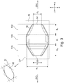
- FIG. 3 is a schematic plan view of a cutting member guide 36 of a razor cartridge 20 according to the first aspect.
- the cutting member guide 36 is provided on a portion of the transverse frame member 35 as a protrusion.
- the cutting member guide 36 is provided as an injection-moulded protrusion of the transverse frame member 35.
- the cutting member guide 36 is integrally formed with the transverse frame member 35.
- each cutting member guide 36 of the plurality of cutting member guides 36a-d is aligned on a common axis of the at least one transverse frame member.
- each cutting member guide of the plurality of cutting member guides is aligned on a central axis 58 of the at least one transverse frame member 35.
- at least one cutting member guide 36 is aligned away from a common axis or central axis 35 of the at least one transverse frame member 35.
- the cutting member guide 36 illustrated in Figure 3 has a complicated shape, and it will be appreciated by a skilled person that not all details of the shape illustrated in Figure 3 are essential features.
- the cutting member guide 36 is divided into a leading longitudinal portion 53a, an intermediate longitudinal portion 53b, and a trailing longitudinal portion 53c.
- the leading longitudinal portion 53a comprises a first planar face 50 running parallel to the direction of a longitudinal cutting member 28 (not shown in Figure 3 ) when positioned in a cutting member support slot next to the first planar face 50(not shown in Figure 3 ).
- the first planar face 50 of a first cutting member guide 36a makes an interference fit with a cutting member 28.
- the distance that the first planar face 50 of the cutting member guide 36 contacts the cutting member 28 (not shown in Figure 3 ) is the first longitudinal distance d 1 .
- the first longitudinal distance d 1 is defined by the width of the first planar face 50 of the at least one cutting member guide 36 in the cartridge plane CP.
- the cartridge plane CP is illustrated by the dotted line box.
- the intermediate longitudinal portion 53b of the cutting member guide 36 has a wider extent across the cartridge plane CP compared to the first longitudinal distance d1. Therefore, a second longitudinal distance d2 is defined by the width of the intermediate longitudinal portion 53b in the cartridge plane CP.
- the leading longitudinal portion 53a approximates the form of a trapezoid
- the intermediate longitudinal portion 53b approximates the form of a rectangle
- the trailing longitudinal portion 53c also approximates the form of a trapezoid.
- the transverse length of intermediate longitudinal portion 53b may be substantially zero, causing the plan form of the cutting member guide 36 on the cartridge plane CP to resemble an irregular hexagon or truncated diamond.
- the total transverse length of the cutting member guide 36 illustrated in Figure 3 is the sum of the transverse lengths (d3 + d4 + d5) of the leading longitudinal portion 53a, the intermediate longitudinal portion 53b, and the trailing longitudinal portion 53c.
- the total transverse length (d3, d4, d5) of the at least one cutting member guide (36) is in the range of 0.30mm to 1.00mm.
- the ratio of the first longitudinal distance d1 and the second longitudinal distance d2 is in the range 0.1 : 0.8. More specifically, the ratio is in the range 0.2 : 0.7. More specifically, the ratio is in the range 0.3 : 0.6. More specifically, the ratio is in the range 0.45 : 0.55.
- the first longitudinal distance d1 is 0.35mm
- the second longitudinal distance d2 is 1.0mm, providing a ratio of 0.35
- the leading longitudinal portion 53a has a length in the transverse direction (-y to y) of 0.60mm
- the intermediate longitudinal portion 53b has a length in the transverse direction (-y to y) of 0.48mm
- the trailing longitudinal portion 53c has a length in the transverse direction (-y to y) of 0.50mm.
- the described trapezoidal shape of the leading longitudinal portion 53a and/or the trailing longitudinal portion 53c of the cutting member guide 36 enhances the strength of the cutting member guides which consequently ensures that the cutting members will be steadily held within the shaving head. This prevents or reduces cutting member deflection during shaving.
- a leading longitudinal portion 53a and/or a trailing longitudinal portion 53c of the at least one cutting member guide 36 has the form of a trapezium in the cartridge plane CP.
- the cutting member guide 36 further comprises a second planar face 52 proximate to a second cutting member support slot and on the opposite side of the cutting member guide 36 to the side having the first planar face 50.
- a third longitudinal distance d6 is defined by the width of the second planar face 52 of the cutting member guide 36 in the cartridge plane CP.
- a ratio of the third longitudinal distance d6 in the cartridge plane DP and the second longitudinal distance d2 in the cartridge plane CP is in the range 0.1: 0.8.
- the cutting member guide 36 has the form of a truncated rhombus in the cartridge plane CP.
- a truncated rhombus 54 is illustrated in Figure 3 by a dotted line inset.
- An effect is that a cutting member guide 36 in the form of a truncated rhombus is stiffer, and can support a cutting member 28a in a razor cartridge 20 with a greater degree of stability.
- each cutting member guide 36 of the plurality of cutting member guides 36 has the form of a truncated rhombus in the cartridge plane CP.
- a skilled person will appreciate that not all of the cutting member guides 36 of a razor cartridge need to meet the condition for the beneficial effect to be achieved.
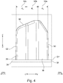
- FIG 4 is a schematic side view of the same cutting member guide 36 illustrated in Figure 3 .
- the cutting member guide 36 is an integral protuberance of a transverse frame member 35.
- the upper portion of the cutting member guide 36 has an arbitrary height and shape suitable for accommodating the transverse cross section of a cutting member.
- the member guide 36 underlying the bent blade may have a curved profile.
- Figure 5 is a schematic end view of a first end of the same cutting member guide 36 illustrated in Figure 3 showing the first planar face 50.
- Figure 6 is a schematic end view of a second end of the same cutting member guide 36 illustrated in Figure 3 showing the second planar face 52.
- a cutting member guide 36 in accordance with the first aspect may have many different shapes, provided the ratio of the first longitudinal distance d1 and the second longitudinal distance d2 (as described above) is in the range 0.1 : 0.8. Furthermore, where a plurality of cutting member guides 36 is provided, a subset of cutting member guides in a plurality of cutting member guides may have a different shape provided at least one cutting member guide 36 has a first longitudinal distance d1 and a second longitudinal distance d2 (as described above) having a ratio in the range 0.1 : 0.8.
- Figure 7a is a schematic plan view of three cutting member guides 36 arranged along a common centre line 58 of a transverse frame member 35 of a razor cartridge 20.
- Figure 7a illustrates a first 36a cutting member guide 36a, a second 36b cutting member guide 36b, and a third 36c cutting member guide 36c.
- the first, second, and third cutting member guides have the same shape.
- each cutting member guide of the plurality of cutting member guides 36 may have a different shape, provided one cutting member guide has a ratio of the first longitudinal distance d1 (of a first planar face 50) and the second longitudinal distance d2 is in the range 0.1 : 0.8.
- Figure 7a also demonstrates a leading end support 60 comprising a cutting member guide in the form of a trapezium in the cartridge plane CP, and a trailing end support 62 comprising a cutting member guide 36 in the form of a trapezium in the cartridge plane CP.
- the leading end support 60 and the trailing end support 62 may have different shapes.
- the leading end support 60 and/or the trailing end support 62 comprise planar faces that contact a cutting member 36 (not shown in Figure 7a ).
- the leading end support 60 and the trailing end support 62 comprise a width greater than their respective planar faces at the portion where they respectively join the leading longitudinal member 24 or the trailing longitudinal member of the frame 21.
- the ratio of the width of the planar face of the leading end support 60 and the width of the portion of the leading end support 60 that contacts the leading longitudinal member 24 is also in the range 0.1 : 0.8.
- the ratio of the width of the planar face of the trailing end support 62 and the width of the portion of the trailing end support 62 that contacts the trailing longitudinal member 25 is in the range 0.1 : 0.8.
- the razor cartridge 20 exemplified in Figure 7a has a frame intended to hold four cutting members 28a-d, in a first cutting member support slot 64a, second cutting member support slot 64b, third cutting member support slot 64c, and fourth cutting member support slot 64d.
- the cutting member support slots are formed by the planar faces of two consecutive cutting member guides 36 and/or one cutting member guide 36 in combination with the leading end support 60 or the trailing end support 62.
- the distance d7 in the transverse direction (-y to y) of the cartridge plane CP (transverse length) between the planar faces of two consecutive cutting member guides 36 and/or one cutting member guide 36 in combination with the leading end support 60 or the trailing end support 62 that form the cutting member support slots 64a-d is in the range 0.1mm to 0.35mm, and more specifically 0.15mm to 0.3mm.
- Figure 7b is a schematic side view of the first 36a, second 36b, third 36c cutting member guides 36 arranged along a common centre line of a transverse frame member 35 of a razor cartridge 20 illustrated in Figure 7a .
- Figure 8 is a schematic plan view of a frame 21 according to an embodiment with the cutting members and retainers omitted.
- a first 35a transverse frame member and a second 35b transverse frame member comprising cutting member guides 36 are shown.
- the first plurality of cutting member guides 36 is provided as three integral protuberances from a first transverse frame member 35a.
- the second plurality of cutting member guides 36 is provided as three integral protuberances from a second transverse frame member 35b.
- the first plurality of cutting member guides 36 and the second plurality of cutting member guides respectively, centrally oriented on a central axis 58 on their respective transverse frame members 35a and 35b.
- the cutting member guides 36 could be provided at an offset from the central axes 58 of the respective transverse frame members 35a and 35b.
- Figure 8 illustrates another advantage of using cutting member guides 36 according to the first aspect.
- the improved strength and firmness of the cutting member guides 36 means that a razor cartridge 20 having a reduced number of transverse frame members 35 but a comparable cutting member stiffness can be provided.
- a razor cartridge 20 having cutting member guides 36 on the transverse frame members 35 that are not in accordance with the first aspect provides less cutting member stiffness.
- three transverse frame members 35 may be required rather than two transverse frame members 35. This is of practical importance, because an increased number of transverse frame members 35 reduces the effectiveness of a water rinse of the razor cartridge 20 by blocking the passage of water through the razor cartridge 20.
- the special shape of the cutting member guides 36 disclosed herein enables the number of transverse frame members 35 to be reduced, whilst substantially maintaining stiffness of the cutting members 28a-d in use, improving the debris washing potential of a razor cartridge 20 in accordance with the first aspect.
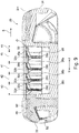
- Figure 9 is a schematic side view of an alternative razor cartridge design in accordance with the first aspect showing the cutting members fitted in position.
- Figure 9 illustrates an alternative razor cartridge design in accordance with the first aspect comprising, for example, a longitudinal skincare element 50 held on an example longitudinal trailing assembly 49.
- the alternative razor cartridge comprises a trimming blade assembly 53.
- the example longitudinal trailing assembly 49 may be omitted without loss of generality.
- Figure 9 illustrates cutting members 28a-d comprising blade supports 32a - 32d and their blades 33 positioned in-between the cutting member guides 36a-36d.
- the razor cartridge 20 is designed to accommodate two, three, four, five, six, or more cutting members 28a-d comprising blade supports 32a - 32d (and their blades).
- the blade supports 32a - 32d each comprise blades facing towards the shaving plane SH (not illustrated).
- the blade supports 32a - 32d each comprise blades facing away from the shaving plane SH.
- the blades may be mounted "underneath the blade support".
- the phrase "underneath the blade support” for the purposes of this specification means a side of a blade support of a razor cartridge that is furthest from a shaving plane SH (skin) of a user when the razor cartridge is in use, as illustrated in Figure 9 .
- the blade guides 36a-36d are configured to support "bent blades" having a radiused portion in which the cutting edge is integral with (formed from the same piece of metal) as the blade support, as known to a skilled person.
- Blade guides 36a-36d configured to support "bent blades” may, for example, comprise a curved upper portion configured to support or accommodate the radius portion of the "bent blade”; for example.
- a leading cutting member to frame span 44 is the transverse span (substantially aligned with the shaving direction S) that is perpendicular to the longitudinal orientation of the cutting member 28a of the group of cutting members 28a-d that spans the space between the internal leading longitudinal wall of the cutting member receiving section 55 that is closest to a shaving plane SH in use (the origin) and the cutting edge 30d of the leading cutting member of the group of cutting members 28a-d.
- a leading inter-blade span 40 that is the closest inter-blade span to the leading longitudinal side 24 of the razor cartridge is a transverse span (substantially aligned with the shaving direction S in use) that is substantially perpendicular to the longitudinal orientation of the cutting members 28 of the group of cutting members 28a-d.
- the leading inter-blade span 40 begins at a point on cutting edge 30a and ends on to a corresponding point on the cutting edge 30c of the first intermediate blade 33b.
- a first intermediate inter-blade span 41 is a transverse span (substantially aligned with the shaving direction S in use) that is substantially perpendicular to the longitudinal orientation of the cutting members of the group of cutting members 28a-d.
- the first intermediate inter-blade span 41 begins at a point on cutting edge 30b and ends on a corresponding point on the cutting edge 30c of the second intermediate blade 33b.
- a trailing inter-blade span 42 is a transverse span (substantially aligned with the shaving direction S in use) that is perpendicular to the longitudinal orientation of the cutting members 28 of the group of cutting members 28a-d.
- the trailing inter-blade span 42 begins a point on cutting edge 30c and ends on a corresponding point on the cutting edge 30d of the blade 33a that is closest to the trailing longitudinal side 25 of the razor cartridge 20.
- a trailing blade to frame span 45 that is a transverse span (substantially aligned with the shaving direction S in use) that is perpendicular to the longitudinal orientation of the cutting members of the group of cutting members 28a-d the cutting edge 30a and a corresponding point on the internal trailing longitudinal wall of cutting member receiving section 56.
- the total span of the cutting member receiving section 31 corresponds to the sum of spans 44, 40, 41, 42, and 45.
- the total span of the cutting member receiving section may be in the range of 7 to 15 mm.
- each cutting member mounting portion 71 is disposed on an inner surface 66 of a respective blade support 32 that, in use, faces away from a shaving plane SH.
- the cutting edge 30 extends forward from the front of the blade support 32.
- the blade support 32 has a non-negligible thickness.
- the blade support 32 has a thickness in the range 0.12 mm - 0.21 mm, and more specifically in the range 0.155 mm - 0.185, and most specifically 0.17 mm.
- At least one blade support 32 of the group of cutting members 28a-d has a different thickness and/or tilt angle to the remainder of the blade supports 32.
- a leading blade to frame span 44 is a transverse span (substantially aligned with the shaving direction S in use) that is perpendicular to the longitudinal orientation of the cutting members of the group of cutting members 28a-d.
- the leading blade to frame span 44 begins at a point on the internal leading longitudinal wall 55 that is, in an example, closest to the shaving plane SH.
- the leading blade to frame span ends at a corresponding point on the cutting edge 30a of the blade 33a of the leading cutting member 28a that is in an example, closest to the shaving plane SH.
- leading frame to blade span 44 is 0.5 mm to 0.9 mm, and specifically 0.7 mm
- a trailing blade to frame span 45 is a transverse span (substantially aligned with the shaving direction S in use) that is perpendicular to the longitudinal orientation of the cutting members of the group of cutting members 28a-d.
- the following blade to frame span begins at a point on the cutting edge 30d of the blade 33d of the trailing cutting member 28a-d.
- the trailing blade to frame span 45 ends at a corresponding point on the internal trailing longitudinal wall 57 that is, in an example, closest to the shaving plane SH.
- the trailing frame to blade span 44 is 1.6 mm to 2.0 mm, and specifically 1.8 mm. In an example, the leading blade to frame span 44 is greater than the trailing blade to frame span 45. In an example, the leading blade to frame span 44 is smaller than the trailing blade to frame span 45. In an example, the leading blade to frame span 44 is substantially equal to than the trailing blade to frame span 45. In an example, the leading blade to frame span 44 is greater than the leading inter-blade span 40. In an example, the leading blade to frame span 44 is substantially equal to than the leading inter-blade span 40. In an example, the leading blade to frame span 44 is smaller than to the leading inter-blade span 40.
- the trailing blade to frame span 45 is greater than the trailing inter-blade span 42. In an example, the trailing blade to frame span 45 is substantially equal to the trailing inter-blade span 42. In an example, the trailing blade to frame span 45 is smaller than the trailing inter-blade span 42. In an example, the first intermediate inter-blade span 41 and the second intermediate inter-blade span 42 are each substantially equal to the leading inter-blade span 40. In an example, the first intermediate inter-blade span 41 and the second intermediate inter-blade span are each substantially equal to the trailing inter-blade span 42. In an example, the first intermediate inter-blade span 41 is less than the leading inter-blade span 41 and greater than the second intermediate inter-blade span.
- the second intermediate inter-blade span is equal to the trailing inter-blade span 42.
- a leading inter-blade span that is closest to the leading longitudinal side of the razor cartridge is greater than a trailing inter-blade span that is closest to the trailing longitudinal side of the razor cartridge.
- Figure 9 also illustrates a debris run-off portion underneath the group of cutting members 28a-d.
- the width of the debris run-off portions is defined by the relative spacing of the cutting members of the group of cutting members 28a-d.
- An effect of variable inter blade spacing is that, in use, a greater amount of hair clippings and foam can be removed via the first (relatively wider) debris run-off portion. This reduces the risk of blockage of the debris run-off portions, particularly when the razor cartridge is used by infrequent shaver users, because the most troublesome debris can escape via the first (relatively wider) debris run-off portion.
- the leading blade to frame span 44 may be larger than, equal to, or smaller than the leading inter-blade span 40.
- the trailing blade to frame span 45 may be larger than, equal to, or smaller than the trailing inter-blade span 42.
- the leading inter-blade span 40 is greater than the trailing inter-blade span 42.
- the first intermediate inter-blade span is equal to, or less than, the leading inter-blade span. In an example, the first intermediate inter-blade span is equal to, or greater than, the trailing inter-blade span.
- the present specification also includes a razor cartridge comprising three cutting members 28, or greater than four cutting members 28.
- five substantially parallel cutting members 28 may be disposed in a shaving direction of the razor cartridge 20, wherein a second intermediate inter-blade span is defined adjacent to the trailing inter-blade span 42.
- first intermediate inter-blade span 41 and the second intermediate inter-blade span are each substantially equal to the leading inter-blade span. In an example, the first intermediate inter-blade span 41 and the second intermediate inter-blade span are each substantially equal to the trailing inter-blade span 42. In an example, the first intermediate inter-blade span is less than the leading inter-blade span 40 and greater than the second intermediate inter-blade span. In an example, the second intermediate inter-blade span is equal to the trailing inter-blade span 42.
- consecutive inter-blade spans of the razor cartridge successively decrease between the leading longitudinal side 24 and the trailing longitudinal side 25 of the razor cartridge in the shaving direction.
- each of the supports 32a-d comprises a shaving plane contact portion 58 that is configured, in use, to contact the shaving plane SH in addition to the cutting edges 30 of the blades, thereby reducing the pressure at each cutting edge contact point with the shaving plane. The pressure at the cutting edge contact points may therefore be reduced.
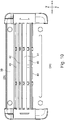
- Figure 10 is a schematic plan view of the alternative razor cartridge 20 having variable inter-blade spacing.
- a razor cartridge 20 according to the first aspect in embodiments, have a variable inter-blade span IBS.
- the spacing of the cutting members is progressively decreased between the leading longitudinal side 24 and the trailing longitudinal side 25 of the razor 20 to generate the variable inter-blade span IBS.
- This has the advantage of providing a relatively large inter-blade space towards the leading longitudinal side 24 of the razor cartridge 20, enabling a wider path for thick debris (cut hairs) to escape.
- a relatively smaller inter-blade space is provided towards the trailing longitudinal side 25 of the razor cartridge 20, enabling a thinner inter-blade spacing that supports the skin more effectively.
- the spacing of the cutting members 28a-d can be progressively increased between the leading longitudinal side 24 and the trailing longitudinal side 25.
- variable inter-blade spacing with a progressively increasing or decreasing inter-blade spacing between the leading longitudinal side 24 and the trailing longitudinal side 25
- variations in the dimensions and/or spacing of the blade guides 36a-d are needed to generate the variable inter-blade spacing.
- variable inter-blade spacing is generated by progressively adjusting the dimensions of the cutting member guides 36a-36d between the leading longitudinal member 24 and the trailing longitudinal member 25.
- a first cutting member guide 36a and a second cutting member guide 36b are provided on a common transverse frame member 35.
- the first cutting member guide 36a is closer to the leading longitudinal member 24 than the second cutting member guide 36b.
- the trailing longitudinal portion 52c of the first cutting member guide 36a and/or the intermediate longitudinal portion 52b of the first cutting member guide 36 are dimensioned to be longer in the transverse direction than the trailing longitudinal portion 52c of the second cutting member guide 36a and/or the intermediate longitudinal portion 52b of the second cutting member guide 36.
- Many different transverse dimensions of intermediate and trailing longitudinal portions may be selected, provided the dimensions of the cutting member guides 64 are sufficient to hold the cutting members in place and generate variable inter-blade spacing.
- a razor cartridge comprising:
- a razor handle 2 According to a third aspect, there is provided a razor handle 2;
- kit of parts comprising a razor cartridge holder comprising a plurality of razor cartridges 20 according to the first aspect or its embodiments, and optionally a razor handle 2.
- thumb rest 48 providing a plurality of cutting members... 8 pivotable bearing member 9 handle grips 49 longitudinal trailing assembly 12 bulging 50 first planar face 14 skin contact point 52 second planar face 16 first side portion 53a leading portion of guide 18 second side portion 53b intermediate portion of guide 20 razor cartridge 53c trailing portion of guide 21 frame 54 truncated rhombus 22 platform member 55 leading longitudinal wall 23 guard member 56 cutting member receiving section 24 leading longitudinal member 58 common centre line 25 trailing longitudinal member 60 leading end support 26 first retainer 62 trailing end support 27 second retainer 64a-d cutting member support slots 28a-d cutting member 66 first plurality of blade guides 30a-d cutting edge 68 second plurality of blade guides
Landscapes
- Life Sciences & Earth Sciences (AREA)
- Forests & Forestry (AREA)
- Engineering & Computer Science (AREA)
- Mechanical Engineering (AREA)
- Physics & Mathematics (AREA)
- Geometry (AREA)
- Packaging Of Annular Or Rod-Shaped Articles, Wearing Apparel, Cassettes, Or The Like (AREA)
- Knives (AREA)
- Dry Shavers And Clippers (AREA)
Abstract
Description
- The aspects described in the following disclosure relate to a razor cartridge, a method for manufacturing a razor cartridge, a shaving razor assembly and an associated kit of parts.
- Razor cartridges (also known as safety razor cartridges) are permanently or removably attached to a razor handle that, in use, is oriented in shaving direction. Razor cartridges typically comprise one or more cutting members, each supporting a blade, mounted perpendicular to the shaving direction. Razor cartridges are also typically provided with a guard (at a leading longitudinal side of the razor cartridge in the shaving direction) and a cap (at a trailing longitudinal side of the razor cartridge in the shaving direction). In use, a user holds the razor handle in the shaving direction and brings the razor cartridge into contact with a portion of skin defining a shaving plane.
- Typically, the shaving plane is defined as the tangential line intersecting the first and second skin contact points of, for example, cutting edges of the shaving head. More simply, the shaving plane may be approximated as a line between the highest points on the skin-contacting surfaced of a razor cartridge - for example, the flat plane between the top of a guard and the top of a cap of the shaving head. Movement of the razor handle causes the blades of the razor cartridge to be moved across the shaving plane in the shaving direction, enabling the blades to remove unwanted hair.
- The performance of razor cartridges may be further improved.
- According to a first aspect, there is provided a razor cartridge comprising a frame. The frame comprises a leading longitudinal member and a trailing longitudinal member defining a cartridge plane, and at least one transverse frame member disposed in between, and joining, the leading longitudinal member and the trailing longitudinal member, in a transverse direction of the razor cartridge.
- The at least one transverse frame member comprises a plurality of cutting member guides defining a plurality of cutting member support slots, each cutting member support slot configured to accommodate a longitudinal cutting member.
- The razor cartridge further comprises a plurality of longitudinal cutting members, wherein each cutting member is disposed in a respective cutting member support slot. At least one cutting member guide comprises a first planar face proximate to a first cutting member support slot. The at least one cutting member guide further comprises an intermediate portion that is a greater distance away from the first cutting member support slot than the first planar face in the transverse direction of the razor cartridge.
- A first longitudinal distance is defined by the width of the first planar face of the at least one cutting member guide in the cartridge plane, and a second longitudinal distance is defined by width of the intermediate portion of the first cutting member guide at the widest point of the first cutting member guide in the cartridge plane.
- A ratio of the first longitudinal distance and the second longitudinal distance is in the range 0.1 : 0.8.
- According to a second aspect, there is provided a method for manufacturing a razor cartridge. The method comprises:
- a) providing a frame comprising a leading longitudinal member and a trailing longitudinal member and at least one transverse frame member defining a cartridge plane, disposed in between, and joining, the leading longitudinal member and the trailing longitudinal member in a transverse direction of the razor cartridge, wherein the at least one transverse frame member comprises a plurality of cutting member guides defining a plurality of cutting member support slots each configured to accommodate a longitudinal cutting member;
wherein at least one cutting member guide comprises a first planar face proximate to a first cutting member support slot, and wherein the at least one cutting member guide further comprises an intermediate portion that is a greater distance away from the first cutting member support slot than the first planar face in the transverse direction of the razor cartridge, and wherein a first longitudinal distance is defined by the width of the first planar face of the at least one cutting member guide in the cartridge plane, and a second longitudinal distance is defined by width of the intermediate portion of the first cutting member guide at the widest point of the first cutting member guide in the cartridge plane, wherein a ratio of the first longitudinal distance and the second longitudinal distance is in the range 0.1 : 0.8; and - b) providing a plurality of cutting members, wherein each cutting member is disposed in a respective cutting member support slot of the at least one transverse frame member.
- According to a third aspect, there is provided a shaving razor assembly comprising: a razor handle, and a razor cartridge according to the first aspect. The razor cartridge is either releasably attached to the razor handle, integrally formed with the razor handle via a non-pivotable connection, or integrally formed with the razor handle via a pivotable connection.
- According to a fourth aspect, there is provided a kit of parts comprising a razor cartridge holder comprising a plurality of razor cartridges according to the first aspect.
- An effect of the aspects discussed above is that the cutting members (blades) of a razor cartridge are supported by cutting member guides that are strengthened owing to their shape. In other words, the cutting member guides can better resist deflection when a force is applied to them by a cutting member support during shaving, for example. Undesired movement of the cutting members during shaving is therefore significantly reduced. The stability of the cutting member guides designed according to the technique discussed herein enables the provision of an open architecture shaver head that facilitates the rinsing and cleansing of debris from the shaver head during shaving.
- Another effect of the aspects discussed above is that a production tool for producing razor cartridges according to aspects discussed herein is simpler, because cutting member guides having thin and sensitive areas are avoided. Cutting member guides comprising such thin and sensitive areas can result in lower production quality and difficulties with repeatability when manufactured with injection moulding systems, for example.
- In the following specification, the term "cutting member" means a component of a razor cartridge that, in use, contacts the skin of a user and cuts protruding hairs. A cutting member can mean at least a razor blade having a blade with a cutting edge glued, or laser welded, to a separate bent support member. The bent support member is fitted into a cutting member support slot in-between two opposed cutting member guides, such as protrusions from a transverse frame member of the razor cartridge. The blade can be attached to the face of the bent support member that faces towards a user of the razor cartridge, in use. Alternatively, the blade can be attached to the face of the bent support member that faces away from a user of the razor cartridge, in use. In this latter case, each cutting member has two contact points with the skin of the user (the blade edge, and the distal end of the bent support member), to thus reduce pressure on the user's skin.
- Alternatively, the cutting member may be a "bent blade". This is an integrally formed cutting member comprising a radiused bend, and a cutting edge formed at a distal end of the radiused bend.
- A "group of cutting members" may consist of the same type of cutting members, or may comprise at least one bent blade, or another type of blade for example.
- In the following specification, the term "cartridge plane" means a plane passing through the joint of one or more protuberances forming cutting member guides with a transverse frame member of the razor cartridge upon which the protuberances are formed. In other words, the cartridge plane is substantially parallel to a shaving plane of the razor cartridge, but the cartridge plane is further away from the shaving plane because it is aligned with the surface nearest to the shaving plane of the transverse frame members of a razor cartridge upon which the protuberances forming the cutting member supports are formed.
- In the following specification, the term "leading" means the side of the razor cartridge that contacts a portion of a user's skin first, in normal use.
- In the following specification, the term "trailing" means the side of the razor cartridge that contacts a portion of a user's skin last, in normal use.
- Embodiments are discussed in the dependent claims and in the detailed description, to which the reader should now refer.
- Other characteristics will be apparent from the accompanying drawings, which form a part of this disclosure. The drawings are intended to further explain the present disclosure and to enable a person skilled in the art to practice it. However, the drawings are intended as nonlimiting examples. Common reference numerals on different figures indicate like or similar features.
-
Figure 1 is a perspective view of a shaving razor assembly. -
Figure 2 is a perspective partial exploded view of a razor cartridge. -
Figure 3 is a schematic plan view of a cutting member guide of a razor cartridge. -
Figure 4 is a schematic side view of a cutting member guide of a razor cartridge. -
Figure 5 is a schematic end view of a first end of a cutting member guide of a razor cartridge. -
Figure 6 is a schematic end view of a second end of a cutting member guide of a razor cartridge. -
Figure 7a is a schematic plan view of several cutting member guides arranged along a common centre line of a transverse frame member of a razor cartridge. -
Figure 7b is a schematic side view of several cutting member guides arranged along a common centre line of a transverse frame member of a razor cartridge. -
Figure 8 is a schematic plan view of a razor cartridge frame member. -
Figure 9 is a schematic side view of an alternative razor cartridge showing the cutting members fitted in position. -
Figure 10 is a schematic plan view of a further alternative razor cartridge having variable inter-blade spacing. -
Figure 11 schematically illustrates a method for manufacturing a razor cartridge. -
Figure 1 is a perspective view of a shavingrazor assembly 1 according to an aspect. The shaving razor assembly comprises cutting members which are not driven by a motor. The shavingrazor assembly 1 comprises ahandle 2 extending in a handle direction H between aproximal portion 4 and adistal portion 6 of thehandle 2. Arazor cartridge 20 is mounted at thedistal portion 6 of thehandle 2. Therazor cartridge 20 will be discussed in more detail following discussion of the shavingrazor assembly 1. - The mounting of the
razor cartridge 20 to thedistal portion 6 of thehandle 2 in the illustration is, in an embodiment, via apivotable bearing member 8, enabling a frame of reference of thehandle 2 to vary relative to a frame of reference of therazor cartridge 20. This enables the angle of the razor cartridge against the skin of a user to vary and adapt to changes during use. - In particular, the
razor cartridge 20 pivots relative to thehandle 2 about the longitudinal axis L of therazor cartridge 20, in use. The pivoting enables the user to adapt to contours of the body, for example. The longitudinal axis L of therazor cartridge 20 is substantially perpendicular to the shaving direction along thehandle 2. Another example of a connection mechanism for connecting therazor cartridge 20 to thehandle 2 is discussed inWO2006/027018 A1 . Another example is arazor cartridge 20 that may pivot relative to a second pivot axis (a rocking axis), substantially perpendicular to axis L. - In examples, the
pivotable bearing member 8 may be omitted (not illustrated) and thehandle 2 provided as an integrally connected part of the support of therazor cartridge 20. - In an example, the
pivotable bearing member 8 may further comprise, or be replaced by, arelease mechanism handle 2. - In an example, the
handle 2 and the support of therazor cartridge 20 are integrally formed with a pivotable bearing member (not illustrated) such as a resilient plastic spring member. - In an example, the
handle 2 is provided with a handle grip 9 formed of a rubber, or rubber-like material to improve gripping friction. In an example, the handle is provided with a thumb-rest 7 to enable a more secure grip of thehandle 2 by a user. -
Figure 2 is a perspective partial exploded view of arazor cartridge 20 according to an example of the first aspect. "Partial exploded view" means that some minor components of therazor cartridge 20 have been omitted from the exploded view to aid clarity of the drawing. - According to a first aspect, there is provided a
razor cartridge 20 comprising aframe 21. Theframe 21 comprises a leadinglongitudinal member 24 and a trailinglongitudinal member 25 and at least onetransverse frame member 35 defining a cartridge plane CP disposed in between, and joining, the leadinglongitudinal member 24 and the trailinglongitudinal member 25, in a transverse direction of therazor cartridge 20. - The at least one
transverse frame member 35 comprises a plurality of cutting member guides 36a-d defining a plurality of cutting member support slots, each cutting member support slot configured to accommodate a longitudinal cutting member. - The
razor cartridge 20 further comprises a plurality of cuttingmembers 28a-d, wherein each cuttingmember 28a-d is disposed in a respective cutting member support slot. At least one cutting member guide 36a-d comprises a first planar face proximate to a first cutting member support slot. The cutting member guide further comprises an intermediate portion that is a greater distance away from the first cutting member support slot than the first planar face in the transverse direction of therazor cartridge 20. - A first longitudinal distance d1 is defined by the width of the first
planar face 50 of the at least one cuttingmember guide 36a in the cartridge plane CP, and a second longitudinal distance d2 is defined by the width of theintermediate portion 53b of the first cuttingmember guide 36a at the widest point of the first cutting member guide in the cartridge plane CP. - A ratio of the first longitudinal distance d1 and the second longitudinal distance d2 is in the range 0.1 : 0.8.
- The shaving direction S is depicted in
Figure 2 using arrow S. In use, therazor cartridge 20 contacts a shaving plane SH (not shown inFigure 4 ), and is translated by the user across the shaving plane SH in the direction of arrow S. - A
frame 21 may be fabricated partially or completely of synthetic materials, such as plastic, resin, or elastomers. Theframe 21 comprises aplatform member 22 connectable to ahandle 2 of a shavingrazor assembly 1 either integrally, or by a connection mechanism such as a pivotable bearing member 8a or by an interconnecting member (not shown). - In an example, a
guard member 23 is, in an example, provided as a substantially longitudinal edge of therazor cartridge 20. In use, theguard member 23 is the first portion of therazor cartridge 20 to contact uncut hairs, and it is thus located at a leadinglongitudinal member 24 of therazor cartridge 20. The side of therazor cartridge 20 opposite to the leadinglongitudinal member 24 of therazor cartridge 20 and opposite to the shaving direction is the trailinglongitudinal member 25 of therazor cartridge 20. The trailinglongitudinal member 25 is thus the final portion of therazor cartridge 20 to contact the shaving plane SH, in use. - It will be noted that the terms "leading
longitudinal member 24" and "trailinglongitudinal member 25" are used to denote specific locations on therazor cartridge 20, and do not imply or require the absence or presence of a particular feature. For example, aguard member 23 may in one example be located at the side comprising the "leadinglongitudinal member 24", and in another example a trimming blade (not shown inFigure 4 ) may be located at the side comprising the "trailinglongitudinal member 25" in another example, but it is not essential that these sides of therazor cartridge 20 comprise such features. - The
guard member 23, in an example, comprises an elastomeric member (not shown inFigure 2 ). In an example, the elastomeric layer comprises one or more fins extending longitudinally in parallel to theguard member 23 and substantially perpendicularly to the shaving direction. One purpose of such an elastomeric layer is, for example, to tension the skin prior to cutting. - The
razor cartridge 20 may, in embodiments, further comprise a cap member (not shown inFigure 2 ) at, or near to, the trailinglongitudinal side 25 but this is not illustrated in the embodiment ofFigure 2 as an aid to clarity. - The
razor cartridge 20 further comprises a group of cuttingmembers 28a-d accommodated in a cuttingmember receiving section 31 of theframe 21. The group of cuttingmembers 28a-d comprises a plurality oflongitudinal cutting members 28a-d. In embodiments, each of thelongitudinal cutting members 28a-d comprises ablade 33a-d having acutting edge 30a-d. The group of cuttingmembers 28a-d is disposed in theframe 21 longitudinally and transverse to the shaving direction S such that in use, theblades 33a-d of the cuttingmembers 28a-d contact a shaving plane SH and cut hair present on the shaving plane SH as therazor cartridge 20 is moved across the shaving plane SH in the shaving direction S. The particular design of the cuttingmembers 28a-d of the group of cuttingmembers 28a-d will be discussed subsequently. - In an example, a
razor cartridge 20 is provided with three cutting members. In an example, a razor cartridge is provided with four cutting members. In an example, a razor cartridge is provided with five cutting members. In an example, a razor cartridge is provided with six cutting members. In an example, a razor cartridge is provided with seven or more cutting members. - The group of cutting
members 28a-d defines a plurality of substantially parallel inter-blade spans 40, 41, 42. In conventional razor cartridges having blades above the support, with three or more blades, each inter-blade span is measured to be constant in a range of about 1.05 mm to 1.5 mm. - The number of inter-blade spans 40, 41, 42 is one fewer than the number of cutting members. The
frame 21 further comprisesfirst retainer 26 andsecond retainer 27 configured to hold thecutting members 28a-d withinrazor cartridge 20 housing. Theframe 21 further comprises first 16 and second 18 side portions. When therazor cartridge 20 is assembled, the first andsecond side portions guard member 23, a cap member (if present, not shown inFigure 2 ) and the group of cuttingmembers 28a-d. Thefirst side retainer 26 andsecond retainer 27 may comprise, for example, plastic, an elastomer, or a metal material and furthermore may be of a different shape to that illustrated. - Although not illustrated, a
pivotable bearing member 8 may, in an example, be provided on the side of therazor cartridge 20 configured to connect to apivotable handle 2. Such apivotable bearing member 8, in an example, comprises two or more shell bearings configured to connect to the pivotable bearing member 8a of thehandle 2. - In an example, the cutting
members 28a-d comprised in the group of cuttingmembers 28a-d are disposed in therazor cartridge 20 such that twocutting edges 30a,b comprised, respectively, on the two foremost (nearest to the leadinglongitudinal member 24 of the razor cartridge 20) cuttingmembers 28a,b of the group of cuttingmembers 28a-d define a leading inter-blade span that is closest to the leadinglongitudinal side 24 of therazor cartridge 20 and that is greater than a trailing inter-blade span defined between the two cutting edges that are closest to the trailinglongitudinal side 25 of the razor cartridge. An embodiment of arazor cartridge 20 having a variable inter blade span is illustrated further inFigures 9 and10 and discussed subsequently. - The
razor cartridge 20 ofFigure 2 comprises fourresilient fingers first retainer 26. Therazor cartridge 20 comprises four resilient fingers under thesecond retainer 27 that are in transverse corresponding alignment with the fourresilient fingers first retainer 26. - In total, the eight resilient fingers each exert a bias force against
respective cutting members 28a-d of the group of cuttingmembers 28a-d in the direction of the shaving plane SH, such that the cuttingmembers 28a-d of the group of cuttingmembers 28a-d are in a rest position, when therazor cartridge 20 is assembled. In the rest position, the cutting edges 30 of the blades 33 of the cuttingmembers 28a-d, bear against corresponding stop portions at each lateral end of the blades 33 near the first 26 and second 27 retainers, for example. In an example, the stop portions may be the first 26 and second 27 retainer. - Accordingly, the rest position of the cutting
members 28a-d is well defined, enabling a high shaving precision. Of course, the illustrated biasing arrangement has many variations. For example, a further plurality of resilient fingers may be provided on one or more of thetransverse frame members 35. In a simplified razor cartridge design (such as for low cost, disposable razors), the resilient fingers may be omitted. A skilled person will appreciate that the number of resilient fingers 38 to be provided is related to the number of cuttingmembers 28a-d in the group of cuttingmembers 28a-d, and that fewer or more than eight resilient fingers 38 can be provided. - In an example, each cutting
member 28a-d in the group of cuttingmembers 28a-d comprise a longitudinal blade support 32. A longitudinal blade 33 is mounted on the blade support 32. The cutting edge 30 of ablade 28a-d is oriented forward in the direction of shaving S. The blade support 32 of ablade 28a-d is an elongated, bent piece of rigid material. In an example, the blade support 32 is a metal such as austenitic stainless steel. - Each cutting
member 28a-d in the group of cuttingmembers 28a-d is, in an example, resiliently mounted in ablade receiving section 31 of therazor cartridge 20. Theblade receiving section 31 comprises a longitudinal space in therazor cartridge 20 that is sized to accommodate the group of cuttingmembers 28a-d. At least one cuttingmember 28a of the group of cuttingmembers 28a-d, up to all cutting members in the group of cuttingmembers 28a-d may be resiliently mounted in theblade receiving section 31. In the illustrated example ofFigure 2 , the transverse inner sides offrame 21 comprise a plurality of holding slots 34. Each holding slot 34 on the transverse inner sides is configured to accept and retain an end of one side of a blade support 32 of a cuttingmember 28a of the group of cuttingmembers 28a-d so that the cuttingmembers 28a-d of the group of cuttingmembers 28a-d are held in theblade receiving section 31 with a substantially parallel inter-blade span in the transverse direction (-x to x). Therefore, as many holding slots 34 are provided in each transverse inner side offrame 21 as there are blades. - Between the cutting
member receiving section 31 and the handle (in a part adjacent to ahandle 2 connection, for example) there are, in examples, provided one or moretransverse frame members 35 that are integrally formed with theframe 21. Thetransverse frame members 35 comprises a plurality of cutting member guides 36a-d provided as a plurality of protuberances aligned with the holdingslots 34a-d on the transverse inner sides of theframe 21. The cutting member guides 36a-d function to regulate the parallel inter-blade span. -
Figure 3 is a schematic plan view of a cuttingmember guide 36 of arazor cartridge 20 according to the first aspect. The cuttingmember guide 36 is provided on a portion of thetransverse frame member 35 as a protrusion. For example, the cuttingmember guide 36 is provided as an injection-moulded protrusion of thetransverse frame member 35. For example, the cuttingmember guide 36 is integrally formed with thetransverse frame member 35. In an example, each cuttingmember guide 36 of the plurality of cutting member guides 36a-d is aligned on a common axis of the at least one transverse frame member. In another example, each cutting member guide of the plurality of cutting member guides is aligned on acentral axis 58 of the at least onetransverse frame member 35. In another example, at least one cuttingmember guide 36 is aligned away from a common axis orcentral axis 35 of the at least onetransverse frame member 35. - The cutting
member guide 36 illustrated inFigure 3 has a complicated shape, and it will be appreciated by a skilled person that not all details of the shape illustrated inFigure 3 are essential features. - The cutting
member guide 36 is divided into a leadinglongitudinal portion 53a, an intermediatelongitudinal portion 53b, and a trailinglongitudinal portion 53c. The leadinglongitudinal portion 53a comprises a firstplanar face 50 running parallel to the direction of a longitudinal cutting member 28 (not shown inFigure 3 ) when positioned in a cutting member support slot next to the first planar face 50(not shown inFigure 3 ). In an example of an assembledrazor cartridge 20, the firstplanar face 50 of a firstcutting member guide 36a makes an interference fit with a cutting member 28. The distance that the firstplanar face 50 of the cutting member guide 36 contacts the cutting member 28 (not shown inFigure 3 ) is the first longitudinal distance d1. In other words, the first longitudinal distance d1 is defined by the width of the firstplanar face 50 of the at least one cuttingmember guide 36 in the cartridge plane CP. InFigure 3 , the cartridge plane CP is illustrated by the dotted line box. - The intermediate
longitudinal portion 53b of the cuttingmember guide 36 has a wider extent across the cartridge plane CP compared to the first longitudinal distance d1. Therefore, a second longitudinal distance d2 is defined by the width of the intermediatelongitudinal portion 53b in the cartridge plane CP. - In the example of
Figure 3 , the leadinglongitudinal portion 53a approximates the form of a trapezoid, and the intermediatelongitudinal portion 53b approximates the form of a rectangle. In the example ofFigure 3 , the trailinglongitudinal portion 53c also approximates the form of a trapezoid. In an embodiment, the transverse length of intermediatelongitudinal portion 53b may be substantially zero, causing the plan form of the cuttingmember guide 36 on the cartridge plane CP to resemble an irregular hexagon or truncated diamond. - The total transverse length of the cutting
member guide 36 illustrated inFigure 3 is the sum of the transverse lengths (d3 + d4 + d5) of the leadinglongitudinal portion 53a, the intermediatelongitudinal portion 53b, and the trailinglongitudinal portion 53c. - In an embodiment, the total transverse length (d3, d4, d5) of the at least one cutting member guide (36) is in the range of 0.30mm to 1.00mm.
- According to the first aspect, the ratio of the first longitudinal distance d1 and the second longitudinal distance d2 is in the range 0.1 : 0.8. More specifically, the ratio is in the range 0.2 : 0.7. More specifically, the ratio is in the range 0.3 : 0.6. More specifically, the ratio is in the range 0.45 : 0.55.
- In a specific example of a cutting
member guide 36, the first longitudinal distance d1 is 0.35mm, and the second longitudinal distance d2 is 1.0mm, providing a ratio of 0.35. Furthermore, the leadinglongitudinal portion 53a has a length in the transverse direction (-y to y) of 0.60mm. The intermediatelongitudinal portion 53b has a length in the transverse direction (-y to y) of 0.48mm. the trailinglongitudinal portion 53c has a length in the transverse direction (-y to y) of 0.50mm. A skilled person will realize that other dimensions may also be used without departing from the teaching of this specification. - The described trapezoidal shape of the leading
longitudinal portion 53a and/or the trailinglongitudinal portion 53c of the cuttingmember guide 36 enhances the strength of the cutting member guides which consequently ensures that the cutting members will be steadily held within the shaving head. This prevents or reduces cutting member deflection during shaving. - In other words, a leading
longitudinal portion 53a and/or a trailinglongitudinal portion 53c of the at least one cuttingmember guide 36 has the form of a trapezium in the cartridge plane CP. - In an embodiment, the cutting
member guide 36 further comprises a secondplanar face 52 proximate to a second cutting member support slot and on the opposite side of the cuttingmember guide 36 to the side having the firstplanar face 50. A third longitudinal distance d6 is defined by the width of the secondplanar face 52 of the cuttingmember guide 36 in the cartridge plane CP. - A ratio of the third longitudinal distance d6 in the cartridge plane DP and the second longitudinal distance d2 in the cartridge plane CP is in the range 0.1: 0.8.
- According to an embodiment, the cutting
member guide 36 has the form of a truncated rhombus in the cartridge plane CP. Atruncated rhombus 54 is illustrated inFigure 3 by a dotted line inset. An effect is that a cuttingmember guide 36 in the form of a truncated rhombus is stiffer, and can support a cuttingmember 28a in arazor cartridge 20 with a greater degree of stability. In embodiments where a plurality of cutting member guides 36 is provided, each cuttingmember guide 36 of the plurality of cutting member guides 36 has the form of a truncated rhombus in the cartridge plane CP. A skilled person will appreciate that not all of the cutting member guides 36 of a razor cartridge need to meet the condition for the beneficial effect to be achieved. -
Figure 4 is a schematic side view of the same cuttingmember guide 36 illustrated inFigure 3 . The cuttingmember guide 36 is an integral protuberance of atransverse frame member 35. The upper portion of the cuttingmember guide 36 has an arbitrary height and shape suitable for accommodating the transverse cross section of a cutting member. For example, in the case where the cuttingmembers 28a-d comprise bent blades, themember guide 36 underlying the bent blade may have a curved profile. -
Figure 5 is a schematic end view of a first end of the same cuttingmember guide 36 illustrated inFigure 3 showing the firstplanar face 50. This -
Figure 6 is a schematic end view of a second end of the same cuttingmember guide 36 illustrated inFigure 3 showing the secondplanar face 52. - A skilled person will appreciate that a cutting
member guide 36 in accordance with the first aspect may have many different shapes, provided the ratio of the first longitudinal distance d1 and the second longitudinal distance d2 (as described above) is in the range 0.1 : 0.8. Furthermore, where a plurality of cutting member guides 36 is provided, a subset of cutting member guides in a plurality of cutting member guides may have a different shape provided at least one cuttingmember guide 36 has a first longitudinal distance d1 and a second longitudinal distance d2 (as described above) having a ratio in the range 0.1 : 0.8. -
Figure 7a is a schematic plan view of three cutting member guides 36 arranged along acommon centre line 58 of atransverse frame member 35 of arazor cartridge 20.Figure 7a illustrates a first 36a cuttingmember guide 36a, a second 36b cuttingmember guide 36b, and a third 36c cuttingmember guide 36c. In the embodiment ofFigure 7a , the first, second, and third cutting member guides have the same shape. However, a skilled person will appreciate that each cutting member guide of the plurality of cutting member guides 36 may have a different shape, provided one cutting member guide has a ratio of the first longitudinal distance d1 (of a first planar face 50) and the second longitudinal distance d2 is in the range 0.1 : 0.8. -
Figure 7a also demonstrates aleading end support 60 comprising a cutting member guide in the form of a trapezium in the cartridge plane CP, and a trailingend support 62 comprising a cuttingmember guide 36 in the form of a trapezium in the cartridge plane CP. Of course, theleading end support 60 and the trailingend support 62 may have different shapes. In common with the cutting member guides 36, theleading end support 60 and/or the trailingend support 62 comprise planar faces that contact a cutting member 36 (not shown inFigure 7a ). Theleading end support 60 and the trailingend support 62 comprise a width greater than their respective planar faces at the portion where they respectively join the leadinglongitudinal member 24 or the trailing longitudinal member of theframe 21. - In an embodiment, the ratio of the width of the planar face of the
leading end support 60 and the width of the portion of theleading end support 60 that contacts the leadinglongitudinal member 24 is also in the range 0.1 : 0.8. - In an embodiment, the ratio of the width of the planar face of the trailing
end support 62 and the width of the portion of the trailingend support 62 that contacts the trailinglongitudinal member 25 is in the range 0.1 : 0.8. - The
razor cartridge 20 exemplified inFigure 7a has a frame intended to hold fourcutting members 28a-d, in a first cuttingmember support slot 64a, second cuttingmember support slot 64b, third cuttingmember support slot 64c, and fourth cuttingmember support slot 64d. The cutting member support slots are formed by the planar faces of two consecutive cutting member guides 36 and/or one cuttingmember guide 36 in combination with theleading end support 60 or the trailingend support 62. - In embodiments, the distance d7 in the transverse direction (-y to y) of the cartridge plane CP (transverse length) between the planar faces of two consecutive cutting member guides 36 and/or one cutting
member guide 36 in combination with theleading end support 60 or the trailingend support 62 that form the cuttingmember support slots 64a-d is in the range 0.1mm to 0.35mm, and more specifically 0.15mm to 0.3mm. -
Figure 7b is a schematic side view of the first 36a, second 36b, third 36c cutting member guides 36 arranged along a common centre line of atransverse frame member 35 of arazor cartridge 20 illustrated inFigure 7a . -
Figure 8 is a schematic plan view of aframe 21 according to an embodiment with the cutting members and retainers omitted. In particular, a first 35a transverse frame member and a second 35b transverse frame member comprising cutting member guides 36 are shown. The first plurality of cutting member guides 36 is provided as three integral protuberances from a firsttransverse frame member 35a. The second plurality of cutting member guides 36 is provided as three integral protuberances from a secondtransverse frame member 35b. The first plurality of cutting member guides 36 and the second plurality of cutting member guides, respectively, centrally oriented on acentral axis 58 on their respectivetransverse frame members central axes 58 of the respectivetransverse frame members -
Figure 8 illustrates another advantage of using cutting member guides 36 according to the first aspect. The improved strength and firmness of the cutting member guides 36 means that arazor cartridge 20 having a reduced number oftransverse frame members 35 but a comparable cutting member stiffness can be provided. For example, arazor cartridge 20 having cutting member guides 36 on thetransverse frame members 35 that are not in accordance with the first aspect provides less cutting member stiffness. Accordingly, threetransverse frame members 35 may be required rather than twotransverse frame members 35. This is of practical importance, because an increased number oftransverse frame members 35 reduces the effectiveness of a water rinse of therazor cartridge 20 by blocking the passage of water through therazor cartridge 20. - In accordance with a
razor cartridge 20 according to the first aspect, the special shape of the cutting member guides 36 disclosed herein enables the number oftransverse frame members 35 to be reduced, whilst substantially maintaining stiffness of the cuttingmembers 28a-d in use, improving the debris washing potential of arazor cartridge 20 in accordance with the first aspect. -
Figure 9 is a schematic side view of an alternative razor cartridge design in accordance with the first aspect showing the cutting members fitted in position. -
Figure 9 illustrates an alternative razor cartridge design in accordance with the first aspect comprising, for example, alongitudinal skincare element 50 held on an example longitudinal trailingassembly 49. In an example, the alternative razor cartridge comprises atrimming blade assembly 53. A skilled person will appreciate that the example longitudinal trailingassembly 49 may be omitted without loss of generality.Figure 9 illustrates cuttingmembers 28a-d comprising blade supports 32a - 32d and their blades 33 positioned in-between the cutting member guides 36a-36d. - In embodiments, the
razor cartridge 20 is designed to accommodate two, three, four, five, six, ormore cutting members 28a-d comprising blade supports 32a - 32d (and their blades). - In embodiments, the blade supports 32a - 32d each comprise blades facing towards the shaving plane SH (not illustrated).
- In embodiments, the blade supports 32a - 32d each comprise blades facing away from the shaving plane SH. In other words, the blades may be mounted "underneath the blade support". The phrase "underneath the blade support" for the purposes of this specification means a side of a blade support of a razor cartridge that is furthest from a shaving plane SH (skin) of a user when the razor cartridge is in use, as illustrated in
Figure 9 . - In embodiments, the blade guides 36a-36d are configured to support "bent blades" having a radiused portion in which the cutting edge is integral with (formed from the same piece of metal) as the blade support, as known to a skilled person. Blade guides 36a-36d configured to support "bent blades" may, for example, comprise a curved upper portion configured to support or accommodate the radius portion of the "bent blade"; for example.
- A leading cutting member to frame
span 44 is the transverse span (substantially aligned with the shaving direction S) that is perpendicular to the longitudinal orientation of the cuttingmember 28a of the group of cuttingmembers 28a-d that spans the space between the internal leading longitudinal wall of the cuttingmember receiving section 55 that is closest to a shaving plane SH in use (the origin) and thecutting edge 30d of the leading cutting member of the group of cuttingmembers 28a-d. - A leading
inter-blade span 40 that is the closest inter-blade span to the leadinglongitudinal side 24 of the razor cartridge is a transverse span (substantially aligned with the shaving direction S in use) that is substantially perpendicular to the longitudinal orientation of the cutting members 28 of the group of cuttingmembers 28a-d. The leadinginter-blade span 40 begins at a point on cuttingedge 30a and ends on to a corresponding point on thecutting edge 30c of the first intermediate blade 33b. - A first intermediate
inter-blade span 41 is a transverse span (substantially aligned with the shaving direction S in use) that is substantially perpendicular to the longitudinal orientation of the cutting members of the group of cuttingmembers 28a-d. The first intermediateinter-blade span 41 begins at a point on cuttingedge 30b and ends on a corresponding point on thecutting edge 30c of the second intermediate blade 33b. - A trailing
inter-blade span 42 is a transverse span (substantially aligned with the shaving direction S in use) that is perpendicular to the longitudinal orientation of the cutting members 28 of the group of cuttingmembers 28a-d. The trailinginter-blade span 42 begins a point on cuttingedge 30c and ends on a corresponding point on thecutting edge 30d of theblade 33a that is closest to the trailinglongitudinal side 25 of therazor cartridge 20. - A trailing blade to frame
span 45 that is a transverse span (substantially aligned with the shaving direction S in use) that is perpendicular to the longitudinal orientation of the cutting members of the group of cuttingmembers 28a-d thecutting edge 30a and a corresponding point on the internal trailing longitudinal wall of cuttingmember receiving section 56. - Thus, the total span of the cutting
member receiving section 31 corresponds to the sum ofspans - As will subsequently be discussed, each cutting member mounting portion 71 is disposed on an
inner surface 66 of a respective blade support 32 that, in use, faces away from a shaving plane SH. The cutting edge 30 extends forward from the front of the blade support 32. However, the blade support 32 has a non-negligible thickness. For example, the blade support 32 has a thickness in the range 0.12 mm - 0.21 mm, and more specifically in the range 0.155 mm - 0.185, and most specifically 0.17 mm. - In an example, at least one blade support 32 of the group of cutting
members 28a-d has a different thickness and/or tilt angle to the remainder of the blade supports 32. - A leading blade to frame
span 44 is a transverse span (substantially aligned with the shaving direction S in use) that is perpendicular to the longitudinal orientation of the cutting members of the group of cuttingmembers 28a-d. The leading blade to framespan 44 begins at a point on the internal leadinglongitudinal wall 55 that is, in an example, closest to the shaving plane SH The leading blade to frame span ends at a corresponding point on thecutting edge 30a of theblade 33a of the leading cuttingmember 28a that is in an example, closest to the shaving plane SH. - In an example the leading frame to
blade span 44 is 0.5 mm to 0.9 mm, and specifically 0.7 mm - A trailing blade to frame
span 45 is a transverse span (substantially aligned with the shaving direction S in use) that is perpendicular to the longitudinal orientation of the cutting members of the group of cuttingmembers 28a-d. The following blade to frame span begins at a point on thecutting edge 30d of the blade 33d of the trailing cuttingmember 28a-d. The trailing blade to framespan 45 ends at a corresponding point on the internal trailing longitudinal wall 57 that is, in an example, closest to the shaving plane SH. - In an example, the trailing frame to
blade span 44 is 1.6 mm to 2.0 mm, and specifically 1.8 mm. In an example, the leading blade to framespan 44 is greater than the trailing blade to framespan 45. In an example, the leading blade to framespan 44 is smaller than the trailing blade to framespan 45. In an example, the leading blade to framespan 44 is substantially equal to than the trailing blade to framespan 45. In an example, the leading blade to framespan 44 is greater than the leadinginter-blade span 40. In an example, the leading blade to framespan 44 is substantially equal to than the leadinginter-blade span 40. In an example, the leading blade to framespan 44 is smaller than to the leadinginter-blade span 40. In an example, the trailing blade to framespan 45 is greater than the trailinginter-blade span 42. In an example, the trailing blade to framespan 45 is substantially equal to the trailinginter-blade span 42. In an example, the trailing blade to framespan 45 is smaller than the trailinginter-blade span 42. In an example, the first intermediateinter-blade span 41 and the second intermediateinter-blade span 42 are each substantially equal to the leadinginter-blade span 40. In an example, the first intermediateinter-blade span 41 and the second intermediate inter-blade span are each substantially equal to the trailinginter-blade span 42. In an example, the first intermediateinter-blade span 41 is less than the leadinginter-blade span 41 and greater than the second intermediate inter-blade span. - In an example, the second intermediate inter-blade span is equal to the trailing
inter-blade span 42. In an example, a leading inter-blade span that is closest to the leading longitudinal side of the razor cartridge is greater than a trailing inter-blade span that is closest to the trailing longitudinal side of the razor cartridge. -
Figure 9 also illustrates a debris run-off portion underneath the group of cuttingmembers 28a-d. The width of the debris run-off portions is defined by the relative spacing of the cutting members of the group of cuttingmembers 28a-d. An effect of variable inter blade spacing is that, in use, a greater amount of hair clippings and foam can be removed via the first (relatively wider) debris run-off portion. This reduces the risk of blockage of the debris run-off portions, particularly when the razor cartridge is used by infrequent shaver users, because the most troublesome debris can escape via the first (relatively wider) debris run-off portion. - The leading blade to frame
span 44 may be larger than, equal to, or smaller than the leadinginter-blade span 40. The trailing blade to framespan 45 may be larger than, equal to, or smaller than the trailinginter-blade span 42. In an example, the leadinginter-blade span 40 is greater than the trailinginter-blade span 42. In an example, the first intermediate inter-blade span is equal to, or less than, the leading inter-blade span. In an example, the first intermediate inter-blade span is equal to, or greater than, the trailing inter-blade span. - Although a razor cartridge with four cutting
members 28a-d has been illustrated, the present specification also includes a razor cartridge comprising three cutting members 28, or greater than four cutting members 28. For example, five substantially parallel cutting members 28 may be disposed in a shaving direction of therazor cartridge 20, wherein a second intermediate inter-blade span is defined adjacent to the trailinginter-blade span 42. - In an example, the first intermediate
inter-blade span 41 and the second intermediate inter-blade span are each substantially equal to the leading inter-blade span. In an example, the first intermediateinter-blade span 41 and the second intermediate inter-blade span are each substantially equal to the trailinginter-blade span 42. In an example, the first intermediate inter-blade span is less than the leadinginter-blade span 40 and greater than the second intermediate inter-blade span. In an example, the second intermediate inter-blade span is equal to the trailinginter-blade span 42. - In an example, consecutive inter-blade spans of the razor cartridge successively decrease between the leading
longitudinal side 24 and the trailinglongitudinal side 25 of the razor cartridge in the shaving direction. - In an example, each of the
supports 32a-d comprises a shavingplane contact portion 58 that is configured, in use, to contact the shaving plane SH in addition to the cutting edges 30 of the blades, thereby reducing the pressure at each cutting edge contact point with the shaving plane. The pressure at the cutting edge contact points may therefore be reduced. -
Figure 10 is a schematic plan view of thealternative razor cartridge 20 having variable inter-blade spacing. - A
razor cartridge 20 according to the first aspect, in embodiments, have a variable inter-blade span IBS. - Therefore, in one variant, the spacing of the cutting members is progressively decreased between the leading
longitudinal side 24 and the trailinglongitudinal side 25 of therazor 20 to generate the variable inter-blade span IBS. This has the advantage of providing a relatively large inter-blade space towards the leadinglongitudinal side 24 of therazor cartridge 20, enabling a wider path for thick debris (cut hairs) to escape. A relatively smaller inter-blade space is provided towards the trailinglongitudinal side 25 of therazor cartridge 20, enabling a thinner inter-blade spacing that supports the skin more effectively. - Alternatively, the spacing of the cutting
members 28a-d can be progressively increased between the leadinglongitudinal side 24 and the trailinglongitudinal side 25. - In either case of providing a variable inter-blade spacing with a progressively increasing or decreasing inter-blade spacing between the leading
longitudinal side 24 and the trailinglongitudinal side 25, variations in the dimensions and/or spacing of the blade guides 36a-d are needed to generate the variable inter-blade spacing. - According to one embodiment, variable inter-blade spacing is generated by progressively adjusting the dimensions of the cutting member guides 36a-36d between the leading
longitudinal member 24 and the trailinglongitudinal member 25. - For example, turning back to
Figure 3 , a firstcutting member guide 36a and a secondcutting member guide 36b are provided on a commontransverse frame member 35. The firstcutting member guide 36a is closer to the leadinglongitudinal member 24 than the secondcutting member guide 36b. - The trailing
longitudinal portion 52c of the first cuttingmember guide 36a and/or the intermediatelongitudinal portion 52b of the first cuttingmember guide 36 are dimensioned to be longer in the transverse direction than the trailinglongitudinal portion 52c of the secondcutting member guide 36a and/or the intermediatelongitudinal portion 52b of the secondcutting member guide 36. Many different transverse dimensions of intermediate and trailing longitudinal portions may be selected, provided the dimensions of the cutting member guides 64 are sufficient to hold the cutting members in place and generate variable inter-blade spacing. - According to a second aspect, there is provided a method for manufacturing a razor cartridge comprising:
- a) providing 46 a frame comprising a leading longitudinal member and a trailing longitudinal member, and at least one transverse frame member defining a cartridge plane disposed in between, and joining, the leading longitudinal member and the trailing longitudinal member in a transverse direction of the razor cartridge, wherein the at least one transverse frame member comprises a plurality of cutting member guides defining a plurality of cutting member support slots each configured to accommodate a longitudinal cutting member;
wherein at least one cutting member guide comprises a firstplanar face 50 proximate to a first cutting member support slot, and wherein the at least one cutting member guide further comprises an intermediate portion that is a greater distance away from the first cutting member support slot than the firstplanar face 50 in the transverse direction of the razor cartridge, and wherein a first longitudinal distance is defined by the width of the first planar face (50) of the at least one cutting member guide in the cartridge plane, and a second longitudinal distance is defined by width of the intermediate portion of the first cutting member guide at the widest point of the first blade guide in the cartridge plane, wherein a ratio of the first longitudinal distance and the second longitudinal distance is in the range 0.1 : 0.8; and - b) providing 48 a plurality of longitudinal cutting members, wherein each cutting member support is disposed in a respective cutting member support slot of the at least one transverse frame member.
- According to a third aspect, there is provided a
razor handle 2; - a
razor cartridge 20 according to the first aspect or its embodiments, wherein the razor cartridge is either releasably attached to the razor handle, integrally formed with the razor handle via a non-pivotable connection, or integrally formed with the razor handle via a pivotable connection. - According to fourth aspect there is provided a kit of parts comprising a razor cartridge holder comprising a plurality of
razor cartridges 20 according to the first aspect or its embodiments, and optionally arazor handle 2. - In the preceding specification, numerous specific details are set forth in order to provide a thorough understanding. It will be apparent, however, to one having ordinary skill in the art that the specific detail need not be employed to practice the present disclosure. In other instances, well-known materials or methods have not been described in detail in order to avoid obscuring the present disclosure.
- Reference throughout the preceding specification to "one embodiment", "an embodiment", "one example" or "an example", "one aspect" or "an aspect" means that a particular feature, structure or characteristic described in connection with the embodiment or example is included in at least one embodiment of the present disclosure. Thus, appearances of the phrases "in one embodiment", "in an embodiment", "one example" or "an example", "one aspect" or "an aspect" in various places throughout this specification are not necessarily all referring to the same embodiment or example.
- Furthermore, the particular features, structures, or characteristics may be combined in any suitable combinations and / or sub-combinations in one or more embodiments or examples.
REFERENCE NUMERALS H Handle direction 31 cutting member receiving section S Shaving direction 32 blade support SH Shaving plane 33a-d blade L Longitudinal direction 34a-d holding slots IBS inter blade span 35 transverse frame member RO inner radius of curvature 36 cutting member guide T1 Razor blade thickness 38a-d resilient finger T2 Blade support thickness 40 leading inter blade span CP cartridge plane 41 first intermediate inter blade span 1 Shaving razor assembly 42 trailing inter-blade span 2 Handle 43a-d cutting edge to blade span 4 proximal portions 44 leading blade to frame span 5a, 5b release mechanism 45 trailing blade to frame span 6 distal portion 46 providing a frame... 7 thumb rest 48 providing a plurality of cutting members... 8 pivotable bearing member 9 handle grips 49 longitudinal trailing assembly 12 bulging 50 first planar face 14 skin contact point 52 second planar face 16 first side portion 53a leading portion of guide 18 second side portion 53b intermediate portion of guide 20 razor cartridge 53c trailing portion of guide 21 frame 54 truncated rhombus 22 platform member 55 leading longitudinal wall 23 guard member 56 cutting member receiving section 24 leading longitudinal member 58 common centre line 25 trailing longitudinal member 60 leading end support 26 first retainer 62 trailing end support 27 second retainer 64a-d cutting member support slots 28a- d cutting member 66 first plurality of blade guides 30a- d cutting edge 68 second plurality of blade guides
Claims (15)
- A razor cartridge (20) comprising:- a frame (21), wherein the frame comprises a leading longitudinal member (24) and a trailing longitudinal member (25), and at least one transverse frame member (35) defining a cartridge plane (CP), disposed in between, and joining, the leading longitudinal member and the trailing longitudinal member, in a transverse direction of the razor cartridge;
wherein the at least one transverse frame member comprises a plurality of cutting member guides (36) defining a plurality of cutting member support slots (64a-d), each cutting member support slot configured to accommodate a longitudinal cutting member; and- a plurality of longitudinal cutting members (28a-d), wherein each cutting member is disposed in a respective cutting member support slot;
wherein at least one cutting member guide (36) comprises a first planar face (50) proximate to a first cutting member support slot (64a), and wherein the at least one cutting member guide (36) further comprises an intermediate portion (53b) that is a greater distance away from the first cutting member support slot (64a) than the first planar face (50) in the transverse direction of the razor cartridge;
wherein a first longitudinal distance (d1) is defined by a width of the first planar face (50) of the at least one cutting member guide (36) in the cartridge plane, and a second longitudinal distance (d2) is defined by width of the intermediate portion (53b) of the first cutting member guide (36) at the widest point of the first cutting member guide in the cartridge plane; and
wherein a ratio of the first longitudinal distance (d1) and the second longitudinal distance (d2) is in the range 0.1 : 0.8. - The razor cartridge (20) according to claim 1,
wherein each cutting member (36) guide of the plurality of cutting member guides is aligned on a common axis of the at least one transverse frame member (35). - The razor cartridge (20) according to one of claims 1 or 2,
wherein a portion of the at least one cutting member guide (36) has the form of a trapezium in the cartridge plane (CP). - The razor cartridge (20) according to one of the preceding claims,
wherein the at least one cutting member guide (36) further comprises a second planar face (52) proximate to a second cutting member support slot (64b) and on the opposite side of the at least one cutting member guide (36) to the first planar face (50),
wherein a third longitudinal distance is defined by the width of the second planar face (52) of the at least one cutting member guide in the cartridge plane (CP); and
wherein a ratio of the third longitudinal distance (d6) and the second longitudinal distance (d2) is in the range 0.1: 0.8. - The razor cartridge (20) according to one of the preceding claims,
wherein the at least one cutting member guide (36) has the form of a truncated rhombus in the cartridge plane (CP), and optionally wherein each cutting member guide of the plurality of cutting member guides (36) has the form of a truncated rhombus in the cartridge plane. - The razor cartridge (20) according to one of the preceding claims,
wherein the at least one cutting member guide (36) is provided as an integrally formed protuberance of the at least one transverse frame member (35). - The razor cartridge (20) according to one of the preceding claims, further comprising:- a second cutting member guide (36b) spaced apart from the at least one cutting member guide (36a) on the at least one transverse frame member (35);
wherein the first cutting member support slot (64a) has a transverse length (d7) of the at least one transverse frame member bounded by the first planar face (50) of the at least one cutting member guide, and a second planar face (52) of the second cutting member guide (36b). - The razor cartridge (20) according to claim 7,
wherein the transverse length (d7) of the first cutting member support slot is between 0.10 mm and 0.35 mm, and more specifically between 0.15 mm to 0.30 mm. - The razor cartridge (20) according to one of the preceding claims,
wherein each cutting member guide (36a) of the plurality of cutting member guides is uniformly spaced apart from a consecutive cutting member guide (36b) on the transverse frame member. - The razor cartridge (20) according to one of claims 4 to 8,
wherein a total transverse length (d3, d4, d5) of the at least one cutting member guide (36a) is different to the total transverse length of the second cutting member guide (36b) in the direction of the at least one transverse frame member (35). - The razor cartridge (20) according to claim 10,
wherein each cutting member guide (36) of the plurality of cutting member guides has a successively increasing or decreasing total transverse length (d3, d4, d5) in the direction of the at least one transverse frame member (35) to thereby provide a plurality of cutting members (28a-d) having an increasing or decreasing inter-blade span. - The razor cartridge (20) according to any of the preceding claims,
wherein the ratio of the first longitudinal distance (d1) and the second longitudinal distance (d2) is in the range 0.2 : 0.7, more specifically, the ratio is in the range 0.3 : 0.6, and most specifically, the ratio is in the range 0.45 : 0.55. - A method for manufacturing a razor cartridge comprising:a) providing (46) a frame comprising a leading longitudinal member and a trailing longitudinal member, and at least one transverse frame member defining a cartridge plane disposed in between, and joining, the leading longitudinal member and the trailing longitudinal member in a transverse direction of the razor cartridge, wherein the at least one transverse frame member comprises a plurality of cutting member guides defining a plurality of cutting member support slots each configured to accommodate a longitudinal cutting member;
wherein at least one cutting member guide comprises a first planar face (50) proximate to a first cutting member support slot, and wherein the at least one cutting member guide further comprises an intermediate portion that is a greater distance away from the first cutting member support slot than the first planar face (50) in the transverse direction of the razor cartridge, and wherein a first longitudinal distance is defined by the width of the first planar face (50) of the at least one cutting member guide in the cartridge plane, and a second longitudinal distance is defined by width of the intermediate portion of the first cutting member guide at the widest point of the first blade guide in the cartridge plane, wherein a ratio of the first longitudinal distance and the second longitudinal distance is in the range 0.1 : 0.8; andb) providing (48) a plurality of longitudinal cutting members, wherein each cutting member support is disposed in a respective cutting member support slot of the at least one transverse frame member. - A shaving razor assembly (1) comprising:- a razor handle (2);- a razor cartridge (20) according to one of claims 1 to 12, wherein the razor cartridge is either releasably attached to the razor handle, integrally formed with the razor handle via a non-pivotable connection, or integrally formed with the razor handle via a pivotable connection.
- A kit of parts comprising:
a razor cartridge holder comprising a plurality of razor cartridges (20) according to one of claims 1 to 12, and optionally a razor handle (2).
Priority Applications (8)
| Application Number | Priority Date | Filing Date | Title |
|---|---|---|---|
| EP19199652.9A EP3797947B1 (en) | 2019-09-25 | 2019-09-25 | Razor cartridge |
| IL290711A IL290711B1 (en) | 2019-09-25 | 2020-09-04 | Razor cartridge |
| BR112022003316-8A BR112022003316B1 (en) | 2019-09-25 | 2020-09-04 | Cartridge with razor, method for making a cartridge with razor, razor set and kit. |
| US17/634,288 US12318954B2 (en) | 2019-09-25 | 2020-09-04 | Razor cartridge |
| CN202080058903.9A CN114269530B (en) | 2019-09-25 | 2020-09-04 | Razor blade holder |
| KR1020227008861A KR20220066273A (en) | 2019-09-25 | 2020-09-04 | razor cartridge |
| MX2022002199A MX2022002199A (en) | 2019-09-25 | 2020-09-04 | RAZOR CARTRIDGE. |
| PCT/EP2020/074710 WO2021058258A1 (en) | 2019-09-25 | 2020-09-04 | Razor cartridge |
Applications Claiming Priority (1)
| Application Number | Priority Date | Filing Date | Title |
|---|---|---|---|
| EP19199652.9A EP3797947B1 (en) | 2019-09-25 | 2019-09-25 | Razor cartridge |
Publications (2)
| Publication Number | Publication Date |
|---|---|
| EP3797947A1 true EP3797947A1 (en) | 2021-03-31 |
| EP3797947B1 EP3797947B1 (en) | 2024-09-04 |
Family
ID=68069599
Family Applications (1)
| Application Number | Title | Priority Date | Filing Date |
|---|---|---|---|
| EP19199652.9A Active EP3797947B1 (en) | 2019-09-25 | 2019-09-25 | Razor cartridge |
Country Status (7)
| Country | Link |
|---|---|
| US (1) | US12318954B2 (en) |
| EP (1) | EP3797947B1 (en) |
| KR (1) | KR20220066273A (en) |
| CN (1) | CN114269530B (en) |
| IL (1) | IL290711B1 (en) |
| MX (1) | MX2022002199A (en) |
| WO (1) | WO2021058258A1 (en) |
Families Citing this family (5)
| Publication number | Priority date | Publication date | Assignee | Title |
|---|---|---|---|---|
| EP3912773B1 (en) * | 2020-05-20 | 2024-03-06 | BIC Violex Single Member S.A. | Razor head with improved spring fingers |
| EP3912772B1 (en) * | 2020-05-20 | 2024-03-06 | BIC Violex Single Member S.A. | Razor head with improved spring fingers |
| KR102851703B1 (en) * | 2021-11-30 | 2025-09-02 | 주식회사 도루코 | Razor cartridge |
| KR102834794B1 (en) * | 2022-08-11 | 2025-07-17 | 주식회사 도루코 | Razor Cartridge |
| CN116372992A (en) * | 2023-03-29 | 2023-07-04 | 佛山市英吉利电器有限公司 | Shaver |
Citations (6)
| Publication number | Priority date | Publication date | Assignee | Title |
|---|---|---|---|---|
| WO2006027018A1 (en) | 2004-09-07 | 2006-03-16 | Bic-Violex Sa | Razor handle and shaver including such a handle |
| WO2008002069A1 (en) * | 2006-06-29 | 2008-01-03 | Dorco Co., Ltd | Shaver |
| EP2823941A1 (en) * | 2013-07-10 | 2015-01-14 | The Gillette Company | Razor cartridges |
| US20160361827A1 (en) * | 2008-05-30 | 2016-12-15 | Michael Hal Bruno | Blade support for multi-blade razor cartridges |
| EP3492227A1 (en) * | 2017-11-29 | 2019-06-05 | Dorco Co., Ltd. | Razor cartridge |
| WO2019190836A1 (en) * | 2018-03-30 | 2019-10-03 | The Gillette Company Llc | Shaving razor cartridge |
Family Cites Families (14)
| Publication number | Priority date | Publication date | Assignee | Title |
|---|---|---|---|---|
| US6035537A (en) * | 1997-09-30 | 2000-03-14 | The Gillette Company | Razor cartridge with metal clip retaining blades |
| GB2408010B (en) * | 2003-11-17 | 2007-03-28 | Knowledge & Merchandising Inc | Shaving product |
| US9308657B2 (en) * | 2008-05-30 | 2016-04-12 | The Gillette Company | Blade support for multi-blade razor cartridges |
| GB2462086A (en) * | 2008-07-22 | 2010-01-27 | Alon Coresh | Articulated Shaving Set |
| KR20100091622A (en) | 2009-02-11 | 2010-08-19 | 주식회사 도루코 | Integrated cartridge |
| KR20110024234A (en) * | 2009-09-01 | 2011-03-09 | 주식회사 도루코 | Shaver cartridges |
| CA2784116A1 (en) * | 2009-12-18 | 2011-06-23 | The Gillette Company | Razor cartridge with non-cutting element |
| US8726518B2 (en) | 2010-03-16 | 2014-05-20 | The Gillette Company | Shaving razors and cartridges |
| PL2707180T3 (en) * | 2011-05-13 | 2017-06-30 | Edgewell Personal Care Brands, Llc | Razor blade supports |
| EP3113918B1 (en) * | 2013-10-02 | 2020-01-08 | Dorco Co., Ltd. | Razor cartridges |
| PL3072648T3 (en) * | 2015-03-25 | 2017-12-29 | The Gillette Company Llc | Shaving razor cartridge |
| US10773404B2 (en) * | 2015-05-13 | 2020-09-15 | The Gillette Company Llc | Shaving razor cartridge |
| EP3292965B1 (en) * | 2016-09-09 | 2021-05-26 | The Gillette Company LLC | Shaving razor cartridge and method of assembling |
| KR101876232B1 (en) * | 2018-01-02 | 2018-07-10 | 주식회사 도루코 | Razor cartridge |
-
2019
- 2019-09-25 EP EP19199652.9A patent/EP3797947B1/en active Active
-
2020
- 2020-09-04 WO PCT/EP2020/074710 patent/WO2021058258A1/en not_active Ceased
- 2020-09-04 MX MX2022002199A patent/MX2022002199A/en unknown
- 2020-09-04 CN CN202080058903.9A patent/CN114269530B/en active Active
- 2020-09-04 IL IL290711A patent/IL290711B1/en unknown
- 2020-09-04 US US17/634,288 patent/US12318954B2/en active Active
- 2020-09-04 KR KR1020227008861A patent/KR20220066273A/en active Pending
Patent Citations (6)
| Publication number | Priority date | Publication date | Assignee | Title |
|---|---|---|---|---|
| WO2006027018A1 (en) | 2004-09-07 | 2006-03-16 | Bic-Violex Sa | Razor handle and shaver including such a handle |
| WO2008002069A1 (en) * | 2006-06-29 | 2008-01-03 | Dorco Co., Ltd | Shaver |
| US20160361827A1 (en) * | 2008-05-30 | 2016-12-15 | Michael Hal Bruno | Blade support for multi-blade razor cartridges |
| EP2823941A1 (en) * | 2013-07-10 | 2015-01-14 | The Gillette Company | Razor cartridges |
| EP3492227A1 (en) * | 2017-11-29 | 2019-06-05 | Dorco Co., Ltd. | Razor cartridge |
| WO2019190836A1 (en) * | 2018-03-30 | 2019-10-03 | The Gillette Company Llc | Shaving razor cartridge |
Also Published As
| Publication number | Publication date |
|---|---|
| EP3797947B1 (en) | 2024-09-04 |
| BR112022003316A2 (en) | 2022-09-06 |
| IL290711B1 (en) | 2026-06-01 |
| CN114269530A (en) | 2022-04-01 |
| CN114269530B (en) | 2024-06-25 |
| WO2021058258A1 (en) | 2021-04-01 |
| US12318954B2 (en) | 2025-06-03 |
| IL290711A (en) | 2022-04-01 |
| MX2022002199A (en) | 2022-03-11 |
| US20220324128A1 (en) | 2022-10-13 |
| KR20220066273A (en) | 2022-05-24 |
Similar Documents
| Publication | Publication Date | Title |
|---|---|---|
| US11059193B2 (en) | Razor cartridge | |
| US12318954B2 (en) | Razor cartridge | |
| US11691306B2 (en) | Razor cartridge | |
| US12600049B2 (en) | Razor cartridge | |
| US12172331B2 (en) | Razor cartridge | |
| KR20070015143A (en) | Shaver | |
| US20220314478A1 (en) | Shaving razor cartridge | |
| EP2823941A1 (en) | Razor cartridges | |
| RU2822647C1 (en) | Razor cartridge | |
| EP3744489A1 (en) | Razor cartridge | |
| EP3744488B1 (en) | Razor cartridge | |
| BR112022003316B1 (en) | Cartridge with razor, method for making a cartridge with razor, razor set and kit. | |
| EP3868526A1 (en) | Razor cartridge |
Legal Events
| Date | Code | Title | Description |
|---|---|---|---|
| PUAI | Public reference made under article 153(3) epc to a published international application that has entered the european phase |
Free format text: ORIGINAL CODE: 0009012 |
|
| STAA | Information on the status of an ep patent application or granted ep patent |
Free format text: STATUS: THE APPLICATION HAS BEEN PUBLISHED |
|
| AK | Designated contracting states |
Kind code of ref document: A1 Designated state(s): AL AT BE BG CH CY CZ DE DK EE ES FI FR GB GR HR HU IE IS IT LI LT LU LV MC MK MT NL NO PL PT RO RS SE SI SK SM TR |
|
| AX | Request for extension of the european patent |
Extension state: BA ME |
|
| STAA | Information on the status of an ep patent application or granted ep patent |
Free format text: STATUS: REQUEST FOR EXAMINATION WAS MADE |
|
| 17P | Request for examination filed |
Effective date: 20210927 |
|
| RBV | Designated contracting states (corrected) |
Designated state(s): AL AT BE BG CH CY CZ DE DK EE ES FI FR GB GR HR HU IE IS IT LI LT LU LV MC MK MT NL NO PL PT RO RS SE SI SK SM TR |
|
| RAP3 | Party data changed (applicant data changed or rights of an application transferred) |
Owner name: BIC VIOLEX SINGLE MEMBER S.A. |
|
| STAA | Information on the status of an ep patent application or granted ep patent |
Free format text: STATUS: EXAMINATION IS IN PROGRESS |
|
| 17Q | First examination report despatched |
Effective date: 20220928 |
|
| GRAP | Despatch of communication of intention to grant a patent |
Free format text: ORIGINAL CODE: EPIDOSNIGR1 |
|
| STAA | Information on the status of an ep patent application or granted ep patent |
Free format text: STATUS: GRANT OF PATENT IS INTENDED |
|
| INTG | Intention to grant announced |
Effective date: 20240405 |
|
| GRAS | Grant fee paid |
Free format text: ORIGINAL CODE: EPIDOSNIGR3 |
|
| GRAA | (expected) grant |
Free format text: ORIGINAL CODE: 0009210 |
|
| STAA | Information on the status of an ep patent application or granted ep patent |
Free format text: STATUS: THE PATENT HAS BEEN GRANTED |
|
| AK | Designated contracting states |
Kind code of ref document: B1 Designated state(s): AL AT BE BG CH CY CZ DE DK EE ES FI FR GB GR HR HU IE IS IT LI LT LU LV MC MK MT NL NO PL PT RO RS SE SI SK SM TR |
|
| REG | Reference to a national code |
Ref country code: GB Ref legal event code: FG4D |
|
| REG | Reference to a national code |
Ref country code: CH Ref legal event code: EP |
|
| REG | Reference to a national code |
Ref country code: IE Ref legal event code: FG4D |
|
| REG | Reference to a national code |
Ref country code: DE Ref legal event code: R096 Ref document number: 602019058210 Country of ref document: DE |
|
| REG | Reference to a national code |
Ref country code: LT Ref legal event code: MG9D |
|
| REG | Reference to a national code |
Ref country code: NL Ref legal event code: MP Effective date: 20240904 |
|
| PG25 | Lapsed in a contracting state [announced via postgrant information from national office to epo] |
Ref country code: NO Free format text: LAPSE BECAUSE OF FAILURE TO SUBMIT A TRANSLATION OF THE DESCRIPTION OR TO PAY THE FEE WITHIN THE PRESCRIBED TIME-LIMIT Effective date: 20241204 |
|
| PG25 | Lapsed in a contracting state [announced via postgrant information from national office to epo] |
Ref country code: PL Free format text: LAPSE BECAUSE OF FAILURE TO SUBMIT A TRANSLATION OF THE DESCRIPTION OR TO PAY THE FEE WITHIN THE PRESCRIBED TIME-LIMIT Effective date: 20240904 Ref country code: FI Free format text: LAPSE BECAUSE OF FAILURE TO SUBMIT A TRANSLATION OF THE DESCRIPTION OR TO PAY THE FEE WITHIN THE PRESCRIBED TIME-LIMIT Effective date: 20240904 Ref country code: GR Free format text: LAPSE BECAUSE OF FAILURE TO SUBMIT A TRANSLATION OF THE DESCRIPTION OR TO PAY THE FEE WITHIN THE PRESCRIBED TIME-LIMIT Effective date: 20241205 |
|
| PG25 | Lapsed in a contracting state [announced via postgrant information from national office to epo] |
Ref country code: BG Free format text: LAPSE BECAUSE OF FAILURE TO SUBMIT A TRANSLATION OF THE DESCRIPTION OR TO PAY THE FEE WITHIN THE PRESCRIBED TIME-LIMIT Effective date: 20240904 |
|
| PG25 | Lapsed in a contracting state [announced via postgrant information from national office to epo] |
Ref country code: LV Free format text: LAPSE BECAUSE OF FAILURE TO SUBMIT A TRANSLATION OF THE DESCRIPTION OR TO PAY THE FEE WITHIN THE PRESCRIBED TIME-LIMIT Effective date: 20240904 |
|
| PG25 | Lapsed in a contracting state [announced via postgrant information from national office to epo] |
Ref country code: HR Free format text: LAPSE BECAUSE OF FAILURE TO SUBMIT A TRANSLATION OF THE DESCRIPTION OR TO PAY THE FEE WITHIN THE PRESCRIBED TIME-LIMIT Effective date: 20240904 |
|
| PG25 | Lapsed in a contracting state [announced via postgrant information from national office to epo] |
Ref country code: ES Free format text: LAPSE BECAUSE OF FAILURE TO SUBMIT A TRANSLATION OF THE DESCRIPTION OR TO PAY THE FEE WITHIN THE PRESCRIBED TIME-LIMIT Effective date: 20240904 Ref country code: RS Free format text: LAPSE BECAUSE OF FAILURE TO SUBMIT A TRANSLATION OF THE DESCRIPTION OR TO PAY THE FEE WITHIN THE PRESCRIBED TIME-LIMIT Effective date: 20241204 |
|
| PG25 | Lapsed in a contracting state [announced via postgrant information from national office to epo] |
Ref country code: RS Free format text: LAPSE BECAUSE OF FAILURE TO SUBMIT A TRANSLATION OF THE DESCRIPTION OR TO PAY THE FEE WITHIN THE PRESCRIBED TIME-LIMIT Effective date: 20241204 Ref country code: PL Free format text: LAPSE BECAUSE OF FAILURE TO SUBMIT A TRANSLATION OF THE DESCRIPTION OR TO PAY THE FEE WITHIN THE PRESCRIBED TIME-LIMIT Effective date: 20240904 Ref country code: NO Free format text: LAPSE BECAUSE OF FAILURE TO SUBMIT A TRANSLATION OF THE DESCRIPTION OR TO PAY THE FEE WITHIN THE PRESCRIBED TIME-LIMIT Effective date: 20241204 Ref country code: LV Free format text: LAPSE BECAUSE OF FAILURE TO SUBMIT A TRANSLATION OF THE DESCRIPTION OR TO PAY THE FEE WITHIN THE PRESCRIBED TIME-LIMIT Effective date: 20240904 Ref country code: HR Free format text: LAPSE BECAUSE OF FAILURE TO SUBMIT A TRANSLATION OF THE DESCRIPTION OR TO PAY THE FEE WITHIN THE PRESCRIBED TIME-LIMIT Effective date: 20240904 Ref country code: GR Free format text: LAPSE BECAUSE OF FAILURE TO SUBMIT A TRANSLATION OF THE DESCRIPTION OR TO PAY THE FEE WITHIN THE PRESCRIBED TIME-LIMIT Effective date: 20241205 Ref country code: FI Free format text: LAPSE BECAUSE OF FAILURE TO SUBMIT A TRANSLATION OF THE DESCRIPTION OR TO PAY THE FEE WITHIN THE PRESCRIBED TIME-LIMIT Effective date: 20240904 Ref country code: ES Free format text: LAPSE BECAUSE OF FAILURE TO SUBMIT A TRANSLATION OF THE DESCRIPTION OR TO PAY THE FEE WITHIN THE PRESCRIBED TIME-LIMIT Effective date: 20240904 Ref country code: BG Free format text: LAPSE BECAUSE OF FAILURE TO SUBMIT A TRANSLATION OF THE DESCRIPTION OR TO PAY THE FEE WITHIN THE PRESCRIBED TIME-LIMIT Effective date: 20240904 |
|
| REG | Reference to a national code |
Ref country code: AT Ref legal event code: MK05 Ref document number: 1719878 Country of ref document: AT Kind code of ref document: T Effective date: 20240904 |
|
| PG25 | Lapsed in a contracting state [announced via postgrant information from national office to epo] |
Ref country code: NL Free format text: LAPSE BECAUSE OF FAILURE TO SUBMIT A TRANSLATION OF THE DESCRIPTION OR TO PAY THE FEE WITHIN THE PRESCRIBED TIME-LIMIT Effective date: 20240904 |
|
| PG25 | Lapsed in a contracting state [announced via postgrant information from national office to epo] |
Ref country code: IS Free format text: LAPSE BECAUSE OF FAILURE TO SUBMIT A TRANSLATION OF THE DESCRIPTION OR TO PAY THE FEE WITHIN THE PRESCRIBED TIME-LIMIT Effective date: 20250104 Ref country code: PT Free format text: LAPSE BECAUSE OF FAILURE TO SUBMIT A TRANSLATION OF THE DESCRIPTION OR TO PAY THE FEE WITHIN THE PRESCRIBED TIME-LIMIT Effective date: 20250106 |
|
| PG25 | Lapsed in a contracting state [announced via postgrant information from national office to epo] |
Ref country code: RO Free format text: LAPSE BECAUSE OF FAILURE TO SUBMIT A TRANSLATION OF THE DESCRIPTION OR TO PAY THE FEE WITHIN THE PRESCRIBED TIME-LIMIT Effective date: 20240904 Ref country code: SM Free format text: LAPSE BECAUSE OF FAILURE TO SUBMIT A TRANSLATION OF THE DESCRIPTION OR TO PAY THE FEE WITHIN THE PRESCRIBED TIME-LIMIT Effective date: 20240904 |
|
| PG25 | Lapsed in a contracting state [announced via postgrant information from national office to epo] |
Ref country code: EE Free format text: LAPSE BECAUSE OF FAILURE TO SUBMIT A TRANSLATION OF THE DESCRIPTION OR TO PAY THE FEE WITHIN THE PRESCRIBED TIME-LIMIT Effective date: 20240904 Ref country code: AT Free format text: LAPSE BECAUSE OF FAILURE TO SUBMIT A TRANSLATION OF THE DESCRIPTION OR TO PAY THE FEE WITHIN THE PRESCRIBED TIME-LIMIT Effective date: 20240904 |
|
| PG25 | Lapsed in a contracting state [announced via postgrant information from national office to epo] |
Ref country code: CZ Free format text: LAPSE BECAUSE OF FAILURE TO SUBMIT A TRANSLATION OF THE DESCRIPTION OR TO PAY THE FEE WITHIN THE PRESCRIBED TIME-LIMIT Effective date: 20240904 |
|
| PG25 | Lapsed in a contracting state [announced via postgrant information from national office to epo] |
Ref country code: IT Free format text: LAPSE BECAUSE OF FAILURE TO SUBMIT A TRANSLATION OF THE DESCRIPTION OR TO PAY THE FEE WITHIN THE PRESCRIBED TIME-LIMIT Effective date: 20240904 Ref country code: SK Free format text: LAPSE BECAUSE OF FAILURE TO SUBMIT A TRANSLATION OF THE DESCRIPTION OR TO PAY THE FEE WITHIN THE PRESCRIBED TIME-LIMIT Effective date: 20240904 |
|
| REG | Reference to a national code |
Ref country code: CH Ref legal event code: PL |
|
| PG25 | Lapsed in a contracting state [announced via postgrant information from national office to epo] |
Ref country code: LU Free format text: LAPSE BECAUSE OF NON-PAYMENT OF DUE FEES Effective date: 20240925 |
|
| REG | Reference to a national code |
Ref country code: DE Ref legal event code: R097 Ref document number: 602019058210 Country of ref document: DE |
|
| PG25 | Lapsed in a contracting state [announced via postgrant information from national office to epo] |
Ref country code: MC Free format text: LAPSE BECAUSE OF FAILURE TO SUBMIT A TRANSLATION OF THE DESCRIPTION OR TO PAY THE FEE WITHIN THE PRESCRIBED TIME-LIMIT Effective date: 20240904 |
|
| PG25 | Lapsed in a contracting state [announced via postgrant information from national office to epo] |
Ref country code: DK Free format text: LAPSE BECAUSE OF FAILURE TO SUBMIT A TRANSLATION OF THE DESCRIPTION OR TO PAY THE FEE WITHIN THE PRESCRIBED TIME-LIMIT Effective date: 20240904 |
|
| REG | Reference to a national code |
Ref country code: BE Ref legal event code: MM Effective date: 20240930 |
|
| PLBE | No opposition filed within time limit |
Free format text: ORIGINAL CODE: 0009261 |
|
| STAA | Information on the status of an ep patent application or granted ep patent |
Free format text: STATUS: NO OPPOSITION FILED WITHIN TIME LIMIT |
|
| PG25 | Lapsed in a contracting state [announced via postgrant information from national office to epo] |
Ref country code: BE Free format text: LAPSE BECAUSE OF NON-PAYMENT OF DUE FEES Effective date: 20240930 |
|
| PG25 | Lapsed in a contracting state [announced via postgrant information from national office to epo] |
Ref country code: CH Free format text: LAPSE BECAUSE OF NON-PAYMENT OF DUE FEES Effective date: 20240930 |
|
| PG25 | Lapsed in a contracting state [announced via postgrant information from national office to epo] |
Ref country code: IE Free format text: LAPSE BECAUSE OF NON-PAYMENT OF DUE FEES Effective date: 20240925 |
|
| 26N | No opposition filed |
Effective date: 20250605 |
|
| PG25 | Lapsed in a contracting state [announced via postgrant information from national office to epo] |
Ref country code: SE Free format text: LAPSE BECAUSE OF FAILURE TO SUBMIT A TRANSLATION OF THE DESCRIPTION OR TO PAY THE FEE WITHIN THE PRESCRIBED TIME-LIMIT Effective date: 20240904 |
|
| PGFP | Annual fee paid to national office [announced via postgrant information from national office to epo] |
Ref country code: DE Payment date: 20250919 Year of fee payment: 7 |
|
| PGFP | Annual fee paid to national office [announced via postgrant information from national office to epo] |
Ref country code: GB Payment date: 20250923 Year of fee payment: 7 |
|
| PGFP | Annual fee paid to national office [announced via postgrant information from national office to epo] |
Ref country code: FR Payment date: 20250922 Year of fee payment: 7 |
|
| PG25 | Lapsed in a contracting state [announced via postgrant information from national office to epo] |
Ref country code: CY Free format text: LAPSE BECAUSE OF FAILURE TO SUBMIT A TRANSLATION OF THE DESCRIPTION OR TO PAY THE FEE WITHIN THE PRESCRIBED TIME-LIMIT; INVALID AB INITIO Effective date: 20190925 |
|
| PG25 | Lapsed in a contracting state [announced via postgrant information from national office to epo] |
Ref country code: HU Free format text: LAPSE BECAUSE OF FAILURE TO SUBMIT A TRANSLATION OF THE DESCRIPTION OR TO PAY THE FEE WITHIN THE PRESCRIBED TIME-LIMIT; INVALID AB INITIO Effective date: 20190925 |
|
| PG25 | Lapsed in a contracting state [announced via postgrant information from national office to epo] |
Ref country code: TR Free format text: LAPSE BECAUSE OF FAILURE TO SUBMIT A TRANSLATION OF THE DESCRIPTION OR TO PAY THE FEE WITHIN THE PRESCRIBED TIME-LIMIT Effective date: 20240904 |
|
| PG25 | Lapsed in a contracting state [announced via postgrant information from national office to epo] |
Ref country code: SI Free format text: LAPSE BECAUSE OF FAILURE TO SUBMIT A TRANSLATION OF THE DESCRIPTION OR TO PAY THE FEE WITHIN THE PRESCRIBED TIME-LIMIT Effective date: 20240904 |
|
| PG25 | Lapsed in a contracting state [announced via postgrant information from national office to epo] |
Ref country code: LT Free format text: LAPSE BECAUSE OF FAILURE TO SUBMIT A TRANSLATION OF THE DESCRIPTION OR TO PAY THE FEE WITHIN THE PRESCRIBED TIME-LIMIT Effective date: 20240904 |