EP3797691A1 - 3d intracardiac activity presentation - Google Patents
3d intracardiac activity presentation Download PDFInfo
- Publication number
- EP3797691A1 EP3797691A1 EP20197871.5A EP20197871A EP3797691A1 EP 3797691 A1 EP3797691 A1 EP 3797691A1 EP 20197871 A EP20197871 A EP 20197871A EP 3797691 A1 EP3797691 A1 EP 3797691A1
- Authority
- EP
- European Patent Office
- Prior art keywords
- catheter
- electrodes
- catheter electrodes
- dimensional surfaces
- positions
- Prior art date
- Legal status (The legal status is an assumption and is not a legal conclusion. Google has not performed a legal analysis and makes no representation as to the accuracy of the status listed.)
- Granted
Links
Images



Classifications
-
- A—HUMAN NECESSITIES
- A61—MEDICAL OR VETERINARY SCIENCE; HYGIENE
- A61B—DIAGNOSIS; SURGERY; IDENTIFICATION
- A61B5/00—Measuring for diagnostic purposes; Identification of persons
- A61B5/24—Detecting, measuring or recording bioelectric or biomagnetic signals of the body or parts thereof
- A61B5/316—Modalities, i.e. specific diagnostic methods
- A61B5/318—Heart-related electrical modalities, e.g. electrocardiography [ECG]
- A61B5/339—Displays specially adapted therefor
-
- A—HUMAN NECESSITIES
- A61—MEDICAL OR VETERINARY SCIENCE; HYGIENE
- A61B—DIAGNOSIS; SURGERY; IDENTIFICATION
- A61B18/00—Surgical instruments, devices or methods for transferring non-mechanical forms of energy to or from the body
- A61B18/04—Surgical instruments, devices or methods for transferring non-mechanical forms of energy to or from the body by heating
- A61B18/12—Surgical instruments, devices or methods for transferring non-mechanical forms of energy to or from the body by heating by passing a current through the tissue to be heated, e.g. high-frequency current
- A61B18/14—Probes or electrodes therefor
- A61B18/1492—Probes or electrodes therefor having a flexible, catheter-like structure, e.g. for heart ablation
-
- A—HUMAN NECESSITIES
- A61—MEDICAL OR VETERINARY SCIENCE; HYGIENE
- A61B—DIAGNOSIS; SURGERY; IDENTIFICATION
- A61B5/00—Measuring for diagnostic purposes; Identification of persons
- A61B5/0033—Features or image-related aspects of imaging apparatus, e.g. for MRI, optical tomography or impedance tomography apparatus; Arrangements of imaging apparatus in a room
-
- A—HUMAN NECESSITIES
- A61—MEDICAL OR VETERINARY SCIENCE; HYGIENE
- A61B—DIAGNOSIS; SURGERY; IDENTIFICATION
- A61B5/00—Measuring for diagnostic purposes; Identification of persons
- A61B5/06—Devices, other than using radiation, for detecting or locating foreign bodies ; Determining position of diagnostic devices within or on the body of the patient
-
- A—HUMAN NECESSITIES
- A61—MEDICAL OR VETERINARY SCIENCE; HYGIENE
- A61B—DIAGNOSIS; SURGERY; IDENTIFICATION
- A61B5/00—Measuring for diagnostic purposes; Identification of persons
- A61B5/06—Devices, other than using radiation, for detecting or locating foreign bodies ; Determining position of diagnostic devices within or on the body of the patient
- A61B5/061—Determining position of a probe within the body employing means separate from the probe, e.g. sensing internal probe position employing impedance electrodes on the surface of the body
-
- A—HUMAN NECESSITIES
- A61—MEDICAL OR VETERINARY SCIENCE; HYGIENE
- A61B—DIAGNOSIS; SURGERY; IDENTIFICATION
- A61B5/00—Measuring for diagnostic purposes; Identification of persons
- A61B5/24—Detecting, measuring or recording bioelectric or biomagnetic signals of the body or parts thereof
- A61B5/25—Bioelectric electrodes therefor
- A61B5/279—Bioelectric electrodes therefor specially adapted for particular uses
- A61B5/28—Bioelectric electrodes therefor specially adapted for particular uses for electrocardiography [ECG]
- A61B5/283—Invasive
- A61B5/287—Holders for multiple electrodes, e.g. electrode catheters for electrophysiological study [EPS]
-
- A—HUMAN NECESSITIES
- A61—MEDICAL OR VETERINARY SCIENCE; HYGIENE
- A61B—DIAGNOSIS; SURGERY; IDENTIFICATION
- A61B5/00—Measuring for diagnostic purposes; Identification of persons
- A61B5/24—Detecting, measuring or recording bioelectric or biomagnetic signals of the body or parts thereof
- A61B5/316—Modalities, i.e. specific diagnostic methods
- A61B5/318—Heart-related electrical modalities, e.g. electrocardiography [ECG]
- A61B5/33—Heart-related electrical modalities, e.g. electrocardiography [ECG] specially adapted for cooperation with other devices
-
- A—HUMAN NECESSITIES
- A61—MEDICAL OR VETERINARY SCIENCE; HYGIENE
- A61B—DIAGNOSIS; SURGERY; IDENTIFICATION
- A61B5/00—Measuring for diagnostic purposes; Identification of persons
- A61B5/24—Detecting, measuring or recording bioelectric or biomagnetic signals of the body or parts thereof
- A61B5/316—Modalities, i.e. specific diagnostic methods
- A61B5/318—Heart-related electrical modalities, e.g. electrocardiography [ECG]
- A61B5/346—Analysis of electrocardiograms
- A61B5/349—Detecting specific parameters of the electrocardiograph cycle
-
- A—HUMAN NECESSITIES
- A61—MEDICAL OR VETERINARY SCIENCE; HYGIENE
- A61B—DIAGNOSIS; SURGERY; IDENTIFICATION
- A61B5/00—Measuring for diagnostic purposes; Identification of persons
- A61B5/68—Arrangements of detecting, measuring or recording means, e.g. sensors, in relation to patient
- A61B5/6846—Arrangements of detecting, measuring or recording means, e.g. sensors, in relation to patient specially adapted to be brought in contact with an internal body part, i.e. invasive
- A61B5/6847—Arrangements of detecting, measuring or recording means, e.g. sensors, in relation to patient specially adapted to be brought in contact with an internal body part, i.e. invasive mounted on an invasive device
- A61B5/6852—Catheters
- A61B5/6859—Catheters with multiple distal splines
-
- A—HUMAN NECESSITIES
- A61—MEDICAL OR VETERINARY SCIENCE; HYGIENE
- A61B—DIAGNOSIS; SURGERY; IDENTIFICATION
- A61B5/00—Measuring for diagnostic purposes; Identification of persons
- A61B5/68—Arrangements of detecting, measuring or recording means, e.g. sensors, in relation to patient
- A61B5/6846—Arrangements of detecting, measuring or recording means, e.g. sensors, in relation to patient specially adapted to be brought in contact with an internal body part, i.e. invasive
- A61B5/6867—Arrangements of detecting, measuring or recording means, e.g. sensors, in relation to patient specially adapted to be brought in contact with an internal body part, i.e. invasive specially adapted to be attached or implanted in a specific body part
- A61B5/6869—Heart
-
- A—HUMAN NECESSITIES
- A61—MEDICAL OR VETERINARY SCIENCE; HYGIENE
- A61B—DIAGNOSIS; SURGERY; IDENTIFICATION
- A61B5/00—Measuring for diagnostic purposes; Identification of persons
- A61B5/74—Details of notification to user or communication with user or patient; User input means
- A61B5/742—Details of notification to user or communication with user or patient; User input means using visual displays
- A61B5/743—Displaying an image simultaneously with additional graphical information, e.g. symbols, charts, function plots
-
- G—PHYSICS
- G06—COMPUTING OR CALCULATING; COUNTING
- G06T—IMAGE DATA PROCESSING OR GENERATION, IN GENERAL
- G06T15/00—Three-dimensional [3D] image rendering
-
- G—PHYSICS
- G16—INFORMATION AND COMMUNICATION TECHNOLOGY [ICT] SPECIALLY ADAPTED FOR SPECIFIC APPLICATION FIELDS
- G16H—HEALTHCARE INFORMATICS, i.e. INFORMATION AND COMMUNICATION TECHNOLOGY [ICT] SPECIALLY ADAPTED FOR THE HANDLING OR PROCESSING OF MEDICAL OR HEALTHCARE DATA
- G16H30/00—ICT specially adapted for the handling or processing of medical images
- G16H30/20—ICT specially adapted for the handling or processing of medical images for handling medical images, e.g. DICOM, HL7 or PACS
-
- A—HUMAN NECESSITIES
- A61—MEDICAL OR VETERINARY SCIENCE; HYGIENE
- A61B—DIAGNOSIS; SURGERY; IDENTIFICATION
- A61B18/00—Surgical instruments, devices or methods for transferring non-mechanical forms of energy to or from the body
- A61B2018/00053—Mechanical features of the instrument of device
- A61B2018/00214—Expandable means emitting energy, e.g. by elements carried thereon
- A61B2018/00267—Expandable means emitting energy, e.g. by elements carried thereon having a basket shaped structure
-
- A—HUMAN NECESSITIES
- A61—MEDICAL OR VETERINARY SCIENCE; HYGIENE
- A61B—DIAGNOSIS; SURGERY; IDENTIFICATION
- A61B18/00—Surgical instruments, devices or methods for transferring non-mechanical forms of energy to or from the body
- A61B2018/00315—Surgical instruments, devices or methods for transferring non-mechanical forms of energy to or from the body for treatment of particular body parts
- A61B2018/00345—Vascular system
- A61B2018/00351—Heart
-
- A—HUMAN NECESSITIES
- A61—MEDICAL OR VETERINARY SCIENCE; HYGIENE
- A61B—DIAGNOSIS; SURGERY; IDENTIFICATION
- A61B18/00—Surgical instruments, devices or methods for transferring non-mechanical forms of energy to or from the body
- A61B2018/00315—Surgical instruments, devices or methods for transferring non-mechanical forms of energy to or from the body for treatment of particular body parts
- A61B2018/00345—Vascular system
- A61B2018/00351—Heart
- A61B2018/00357—Endocardium
-
- A—HUMAN NECESSITIES
- A61—MEDICAL OR VETERINARY SCIENCE; HYGIENE
- A61B—DIAGNOSIS; SURGERY; IDENTIFICATION
- A61B18/00—Surgical instruments, devices or methods for transferring non-mechanical forms of energy to or from the body
- A61B2018/00571—Surgical instruments, devices or methods for transferring non-mechanical forms of energy to or from the body for achieving a particular surgical effect
- A61B2018/00577—Ablation
-
- A—HUMAN NECESSITIES
- A61—MEDICAL OR VETERINARY SCIENCE; HYGIENE
- A61B—DIAGNOSIS; SURGERY; IDENTIFICATION
- A61B18/00—Surgical instruments, devices or methods for transferring non-mechanical forms of energy to or from the body
- A61B2018/00636—Sensing and controlling the application of energy
- A61B2018/00773—Sensed parameters
- A61B2018/00839—Bioelectrical parameters, e.g. ECG, EEG
-
- A—HUMAN NECESSITIES
- A61—MEDICAL OR VETERINARY SCIENCE; HYGIENE
- A61B—DIAGNOSIS; SURGERY; IDENTIFICATION
- A61B18/00—Surgical instruments, devices or methods for transferring non-mechanical forms of energy to or from the body
- A61B2018/00636—Sensing and controlling the application of energy
- A61B2018/00773—Sensed parameters
- A61B2018/00875—Resistance or impedance
-
- A—HUMAN NECESSITIES
- A61—MEDICAL OR VETERINARY SCIENCE; HYGIENE
- A61B—DIAGNOSIS; SURGERY; IDENTIFICATION
- A61B5/00—Measuring for diagnostic purposes; Identification of persons
- A61B5/68—Arrangements of detecting, measuring or recording means, e.g. sensors, in relation to patient
- A61B5/6846—Arrangements of detecting, measuring or recording means, e.g. sensors, in relation to patient specially adapted to be brought in contact with an internal body part, i.e. invasive
- A61B5/6847—Arrangements of detecting, measuring or recording means, e.g. sensors, in relation to patient specially adapted to be brought in contact with an internal body part, i.e. invasive mounted on an invasive device
- A61B5/6852—Catheters
- A61B5/6853—Catheters with a balloon
-
- A—HUMAN NECESSITIES
- A61—MEDICAL OR VETERINARY SCIENCE; HYGIENE
- A61B—DIAGNOSIS; SURGERY; IDENTIFICATION
- A61B5/00—Measuring for diagnostic purposes; Identification of persons
- A61B5/68—Arrangements of detecting, measuring or recording means, e.g. sensors, in relation to patient
- A61B5/6846—Arrangements of detecting, measuring or recording means, e.g. sensors, in relation to patient specially adapted to be brought in contact with an internal body part, i.e. invasive
- A61B5/6847—Arrangements of detecting, measuring or recording means, e.g. sensors, in relation to patient specially adapted to be brought in contact with an internal body part, i.e. invasive mounted on an invasive device
- A61B5/6852—Catheters
- A61B5/6858—Catheters with a distal basket, e.g. expandable basket
Definitions
- the present invention relates to medical systems, and in particular, but not exclusively, to analysis of electrical activity.
- Electrograms may be measured by unipolar or bipolar leads, and are used, e.g., to determine onset of electrical propagation at a point, known as local activation time (LAT).
- LAT local activation time
- US Patent 5,782,773 to Kuo, et al. describes a three-dimensional electrocardiogram display method for 3-D representation of a plurality of cardiac signals.
- a 3-D rectangular coordinate system is defined to display the 3-D representation of the cardiac signals.
- an amplitude display scheme preferably an amplitude-to-color mapping table, is defined to assign various quantization levels of amplitude to specified distinctive colors.
- graphic processing and display means the 3-D representation of the cardiac signals can be generated and displayed.
- the physicians can choose to observe the 3-D graph in various views, including perspective view, sectional view, and top rectangular view. This allows the physicians to make diagnosis of heart diseases by observing just one or two 3-D representations of the cardiac signals.
- the physicians can thus have an overall integral view over a plentiful number of cardiac signals and thereby make diagnosis about the heart conditions of the patient more easily.
- a computer-implemented method and apparatus for displaying electrical impulse data of a human heart for analysis includes receiving cardiac electrical impulse data produced during a cardiac stress test by a plurality of electrode leads adapted for placement on a patient and calculating parameters for a plurality of display windows based on the data and providing a main display in which the plurality of display windows are positioned.
- a three-dimensional color mapping plot is displayed in one of the plurality of display windows and a two dimensional color mapping plot is displayed in another of the plurality of display windows.
- a plot of raw lead data from at least one lead is displayed in one of the plurality of display windows.
- US Patent Publication 2012/0130232 of Markowitz, et al. describes a volume of a patient that can be mapped with a system operable to identify a plurality of locations and save a plurality of locations of a mapping instrument.
- the mapping instrument can include one or more electrodes that can sense a voltage that can be correlated to a three-dimensional location of the electrode at the time of the sensing or measurement. Therefore, a map of a volume can be determined based upon the sensing of the plurality of points without the use of other imaging devices. An implantable medical device can then be navigated relative to the mapping data.
- the localization system and method can be used with systems that perform cardiac mapping, diagnosis and treatment of cardiac abnormalities, as examples, and in the retrieval, processing, and interpretation of such types of information.
- the localization system and method use high impedance inputs, improved isolation, and relatively high drive currents for pairs of electrodes used to establish a multi-axis coordinate system.
- the axes can be rotated and scaled to improve localization.
- a medical system including a catheter configured to be inserted into a chamber of a heart of a living subject, and including catheter electrodes configured to contact tissue at respective locations within the chamber of the heart, a display, and processing circuitry configured to receive signals from the catheter, and in response to the signals sample voltage values of the signals at respective sampling times, compute respective curved three-dimensional surfaces describing electrical activity of the tissue over the catheter electrodes at respective ones of the sampling times, responsively to (a) respective positions of the respective catheter electrodes, and (b) the respective sampled voltage values indicative of electrical activity of the tissue that is sensed by the respective catheter electrodes at the respective locations at the respective sampling times, and render the respective three-dimensional surfaces to the display over time.
- processing circuitry is configured to color respective regions of the respective three-dimensional surfaces responsively to respective ones of the sampled voltage values.
- the respective positions of the respective catheter electrodes are respective projected positions projected onto a plane
- the processing circuitry is configured to compute respective displacements, perpendicular to the plane, from respective ones of the projected positions of respective ones of the catheter electrodes responsively to respective ones of the sampled voltage values at respective ones of the sampling times
- the processing circuitry is configured to fit the respective curved three-dimensional surfaces describing the electrical activity of the tissue over the catheter electrodes at the respective ones of the sampling times, responsively to respective ones of the displacements, perpendicular to the plane, from respective ones of the projected positions.
- processing circuitry is configured to color respective regions of the respective three-dimensional surfaces responsively to respective ones of the displacements.
- the processing circuitry is configured to sample the voltage values of the signals at the respective sampling times at a rate exceeding ten times per second, and render the respective three-dimensional surfaces to the display over time with a new one of the three-dimensional surfaces being displayed at least every tenth of a second so that the rendered three-dimensional surfaces provide an animation of an activation wave associated with the electrical activity of the tissue over the catheter electrodes.
- the system includes an interface configured to receive user input to change a viewing angle of ones of the three-dimensional surfaces, wherein the processing circuitry is configured to render ones of the three-dimensional surfaces with a different viewing angle responsively to the received user input.
- the catheter includes a shaft having a distal end, and a distal end assembly on which the catheter electrodes are disposed, and the respective positions of the respective catheter electrodes are respective positions derived from a static computer model of the catheter.
- the respective positions of the respective catheter electrodes are respective projected positions projected onto a plane perpendicular to an axis of the shaft.
- the catheter includes a shaft having a distal end, and a distal end assembly on which the catheter electrodes are disposed, and the processing circuitry is configured to compute the respective positions of the respective catheter electrodes.
- respective positions of the respective catheter electrodes are respective projected positions projected onto a plane perpendicular to an axis of the shaft.
- a medical method including receiving signals from a catheter, which is configured to be inserted into a chamber of a heart of a living subject, and including catheter electrodes configured to contact tissue at respective locations within the chamber of the heart, in response to the signals, sampling voltage values of the signals at respective sampling times, computing respective curved three-dimensional surfaces describing electrical activity of the tissue over the catheter electrodes at respective ones of the sampling times, responsively to (a) respective positions of the respective catheter electrodes, and (b) the respective sampled voltage values indicative of electrical activity of the tissue that is sensed by the respective catheter electrodes at the respective locations at the respective sampling times, and rendering the respective three-dimensional surfaces to a display over time.
- the method includes coloring respective regions of the respective three-dimensional surfaces responsively to respective ones of the sampled voltage values.
- the respective positions of the respective catheter electrodes are respective projected positions projected onto a plane
- the method further including computing respective displacements, perpendicular to the plane, from respective ones of the projected positions of respective ones of the catheter electrodes responsively to respective ones of the sampled voltage values at respective ones of the sampling times, and fitting the respective curved three-dimensional surfaces describing the electrical activity of the tissue over the catheter electrodes at the respective ones of the sampling times, responsively to respective ones of the displacements, perpendicular to the plane, from respective ones of the projected positions.
- the method includes sampling the voltage values of the signals at the respective sampling times at a rate exceeding ten times per second, wherein the rendering includes rendering the respective three-dimensional surfaces to the display over time with a new one of the three-dimensional surfaces being displayed at least every tenth of a second so that the rendered three-dimensional surfaces provide an animation of an activation wave associated with the electrical activity of the tissue over the catheter electrodes.
- the method includes receiving user input to change a viewing angle of ones of the three-dimensional surfaces, and rendering ones of the three-dimensional surfaces with a different viewing angle responsively to the received user input.
- the catheter includes a shaft having a distal end, and a distal end assembly on which the catheter electrodes are disposed, and the respective positions of the respective catheter electrodes are respective positions derived from a static computer model of the catheter.
- the respective positions of the respective catheter electrodes are respective projected positions projected onto a plane perpendicular to an axis of the shaft.
- the catheter includes a shaft having a distal end, and a distal end assembly on which the catheter electrodes are disposed, and the method further includes computing the respective positions of the respective catheter electrodes.
- respective positions of the respective catheter electrodes are respective projected positions projected onto a plane perpendicular to an axis of the shaft.
- a software product including a non-transient computer-readable medium in which program instructions are stored, which instructions, when read by a central processing unit (CPU), cause the CPU to receive signals from a catheter, which is configured to be inserted into a chamber of a heart of a living subject, and including catheter electrodes configured to contact tissue at respective locations within the chamber of the heart, in response to the signals, sample voltage values of the signals at respective sampling times, compute respective curved three-dimensional surfaces describing electrical activity of the tissue over the catheter electrodes at respective ones of the sampling times, responsively to (a) respective positions of the respective catheter electrodes, and (b) the respective sampled voltage values indicative of electrical activity of the tissue that is sensed by the respective catheter electrodes at the respective locations at the respective sampling times, and render the respective three-dimensional surfaces to a display over time.
- CPU central processing unit
- Embodiments of the present invention solve the above problems by providing a three-dimensional (3D) presentation including respective curved three-dimensional surfaces which describe electrical activity of tissue over catheter electrodes at respective sampling times.
- Intracardiac (IC) signals which are received from the electrodes of a catheter are collected and sampled at different sampling times.
- the electrical activity of the catheter electrodes at one of the sampling times is plotted on the 3D presentation as a curved 3D surface.
- the 3D presentation may be defined by three axes (x, y and z) or any other suitable coordinate system.
- the x and y axes indicate the 2D position of the electrodes of the catheter (for example, by projecting the electrode position on to a plane defined by the x and y-axes).
- the z-axis indicates the voltage of the electrical activity captured by the electrodes at the sampled time.
- the curved 3D surface is computed by fitting the 3D surface to data points defined by the x-y coordinates of the electrode positions of the catheter electrodes and the respective z-coordinates of the sampled voltage.
- the fitting of the 3D surface may be performed by interpolating (and optionally extrapolating) between the data points mentioned above.
- Regions of the 3D surface may be optionally colored according to the voltage level associated with the regions.
- the 3D presentation may be static (e.g. for single sampling times) or may be dynamic (e.g., a video) showing how the electrical activity moves as an activation wave over the electrodes of the catheter providing the physician with a useful diagnostic tool.
- any suitable catheter may be used in the above embodiments, for example, multi-spline catheters (e.g., a PENTARAY® catheter of Biosense Webster, Inc., Irvine, CA USA, or a basket catheter) or other multi-electrode catheters (e.g., balloon catheter, or Lasso catheter).
- multi-spline catheters e.g., a PENTARAY® catheter of Biosense Webster, Inc., Irvine, CA USA, or a basket catheter
- other multi-electrode catheters e.g., balloon catheter, or Lasso catheter.
- the catheter is inserted into the heart chamber of a living subject.
- the catheter may include a shaft having a distal end, and a distal end assembly on which catheter electrodes are disposed.
- the catheter electrodes contact tissue at respective locations within the heart chamber.
- Processing circuitry receives signals from the catheter, and in response to the signals, samples voltage values of the signals at respective sampling times.
- the processing circuitry computes respective positions of the respective catheter electrodes, for example, responsively to signal(s) received from a position transducer (such as a position sensor or sensors of the catheter or an externally placed sensor(s)).
- a position transducer such as a position sensor or sensors of the catheter or an externally placed sensor(s)
- the positions of the respective catheter electrodes, used in the computations described below are derived from a static computer model of the catheter.
- the positions used in the computations described below may be based on the positions of the deflectable splines in a nondeflected position even if the splines are in fact deflected at the respective sampling time.
- the positions of the catheter electrodes are typically projected positions projected onto a plane (e.g., the x-y axes described above).
- the plane is perpendicular to an axis of the shaft of the catheter.
- the processing circuitry computes respective curved three-dimensional surfaces describing electrical activity of the tissue over the catheter electrodes at respective ones of the sampling times. It should be noted that any one of the three-dimensional surfaces describes electrical activity for a corresponding one of the sampling times and not multiple sampling times.
- the sampled voltages of different sampling times yield different three-dimensional surfaces.
- the three-dimensional surfaces are computed responsively to: (a) respective positions (e.g., two-dimensional position coordinates) of the respective catheter electrodes; and (b) the respective sampled voltage values indicative of electrical activity of the tissue that is sensed by the respective catheter electrodes at the respective locations (on the tissue) at the respective sampling times.
- one three-dimensional surface is computed responsively to: (a) respective positions (e.g., two-dimensional position coordinates) of the respective catheter electrodes; and (b) the respective sampled voltage values sampled at one of the respective sampling times.
- the processing circuitry colors respective regions of the respective three-dimensional surfaces responsively to respective ones of the sampled voltage values.
- the processing circuitry computes respective displacements, perpendicular to the plane (e.g., along the z axis away from the x-y axes), from respective projected positions of respective catheter electrodes responsively to respective sampled voltage values at respective sampling times.
- Each displacement provides a z-axis coordinate when a cartesian coordinate system is used.
- a displacement z n is computed according to the sampled voltage, sampled at time t1, of the signal sensed by electrode number n of the catheter.
- Electrode number n has position coordinates x n ,y n on the plane defined by the x-y axes.
- the data point of electrode number n in the 3D presentation for time t1 has coordinates x n ,y n ,z n .
- the processing circuitry fits the respective curved three-dimensional surfaces describing the electrical activity of the tissue over the catheter electrodes at the respective sampling times, responsively to the respective computed displacements, perpendicular to the plane, from respective ones of the projected positions, e.g., according to the data points representing the electrical activity of each of the electrodes in the coordinate system.
- the processing circuitry colors respective regions of the respective three-dimensional surfaces responsively to respective ones of the displacements.
- a user interface may receive user input to change a viewing angle of the three-dimensional surfaces, which may then be rendered with a different viewing angle responsively to the received user input.
- FIG. 1 is a partly pictorial, partly block diagram view of a cardiac analysis system 10 constructed and operative in accordance with an embodiment of the present invention.
- Fig. 1 is a pictorial illustration of a cardiac analysis system 10, constructed and operative in accordance with a disclosed embodiment of the invention, for computing and evaluating electrical activity and optionally for performing ablative procedures on a heart 12 of a living subject.
- the system comprises a catheter 14, such as a catheter, which is percutaneously inserted by an operator 16 through the patient's vascular system into a chamber or vascular structure of the heart 12.
- the operator 16 who is typically a physician, brings a distal tip 18 of the catheter 14 into contact with the heart wall, for example, at an ablation target site or to capture electrical potentials over time at multiple sample location over a surface of one or more chambers of the heart 12.
- Electrical activation maps may be prepared, according to the methods disclosed in U.S. Patents 6,226,542 , 6,301,496 , and 6,892,091 .
- One commercial product embodying elements of the system 10 is available as the CARTO® 3 System, available from Biosense Webster, Inc. This system may be modified by those skilled in the art to embody the principles of the invention described herein.
- Areas determined to be abnormal can be ablated by application of thermal energy, e.g., by passage of radiofrequency electrical current through wires in the catheter to one or more electrodes at the distal tip 18, which apply the radiofrequency energy to the myocardium.
- the energy is absorbed in the tissue, heating it to a temperature (typically about 50°C) at which it permanently loses its electrical excitability.
- this procedure creates non-conducting lesions in the cardiac tissue, which disrupt the abnormal electrical pathway causing the arrhythmia.
- the principles of the invention can be applied to different heart chambers to diagnose and treat many different cardiac arrhythmias.
- the catheter 14 typically comprises a handle 20, having suitable controls on the handle to enable the operator 16 to steer, position and orient the distal tip 18 of the catheter 14 as desired for the ablation.
- a distal portion of the catheter 14 contains position sensors (not shown) that provide signals to processing circuitry 22, located in a console 24.
- the processing circuitry 22 may fulfill several processing functions as described below.
- Ablation energy and electrical signals can be conveyed to and from the heart 12 through catheter electrodes 32 located at or near the distal tip 18 via cable 34 to the console 24.
- the electrodes 32 are configured to contact tissue at respective locations with the chamber of the heart 12 and capture electrical potentials over time at the respective locations.
- other electrodes may be configured to capture electrical potentials over time at multiple sample locations over a surface of one or more chambers of the heart 12.
- Pacing signals and other control signals may be conveyed from the console 24 through the cable 34 and the electrodes 32 to the heart 12.
- the catheter 14 may be implemented without ablation capabilities as an exploratory device having electrodes configured to capture electrical potentials over time at multiple sample locations over a surface of one or more chambers of the heart 12.
- Wire connections 35 link the console 24 with body surface electrodes 30 and other components of a positioning sub-system for measuring location and orientation coordinates of the catheter 14.
- the processing circuitry 22 or another processor may be an element of the positioning sub-system.
- the electrodes 32 and the body surface electrodes 30 may be used to measure tissue impedance at the ablation site as taught in U.S. Patent 7,536,218 .
- a sensor for bioelectric information e.g., a temperature sensor (not shown), typically a thermocouple or thermistor, may be mounted on or near each of the electrodes 32.
- the console 24 typically contains one or more ablation power generators 25.
- the catheter 14 may be adapted to conduct ablative energy to the heart using any known ablation technique, e.g., radiofrequency energy, ultrasound energy, and laser-produced light energy. Such methods are disclosed in U.S. Patents 6,814,733 , 6,997,924 , and 7,156,816 .
- the positioning subsystem comprises a magnetic position tracking arrangement that determines the position and orientation of the catheter 14 by generating magnetic fields in a predefined working volume and sensing these fields at the catheter 14, using field generating coils 28.
- the positioning subsystem is described in U.S. Patents 7,756,576 and 7,536,218 .
- the catheter 14 is coupled to the console 24, which enables the operator 16 to observe and regulate the functions of the catheter 14.
- the processing circuitry 22 may be embodied as a computer with appropriate signal processing circuits.
- the processing circuitry 22 is coupled to drive a display 29 including a display screen 37.
- the signal processing circuits may receive, amplify, filter and digitize signals from the catheter 14, including signals generated by sensors such as electrical, temperature and contact force sensors, and location sensing electrodes (not shown) located distally in the catheter 14.
- the digitized signals are received and used by the console 24 and the positioning sub-system to compute the position and orientation of the catheter 14, and to analyze the electrical signals from the electrodes.
- processing circuitry 22 may be combined in a single physical component or, alternatively, implemented using multiple physical components. These physical components may comprise hard-wired or programmable devices, or a combination of the two. In some embodiments, at least some of the functions of the processing circuitry may be carried out by a programmable processor under the control of suitable software. This software may be downloaded to a device in electronic form, over a network, for example. Alternatively, or additionally, the software may be stored in tangible, non-transitory computer-readable storage media, such as optical, magnetic, or electronic memory.
- the console 24 may also include an interface 39 to receive input commands from the operator 16 via any suitable user input device, for example, but not limited to, a pointing device (such as a mouse of stylus), a keyboard, and/or a touch sensitive screen implemented in the display screen 37.
- a pointing device such as a mouse of stylus
- a keyboard such as a keyboard
- a touch sensitive screen implemented in the display screen 37.
- the system 10 includes other elements, which are not shown in the figures for the sake of simplicity.
- the system 10 may include an electrocardiogram (ECG) monitor, coupled to receive signals from the body surface electrodes 30, in order to provide an ECG synchronization signal to the console 24.
- ECG electrocardiogram
- the system 10 typically also includes a reference position sensor, either on an externally applied reference patch attached to the exterior of the subject's body, or on an internally placed catheter, which is inserted into the heart 12 and maintained in a fixed position relative to the heart 12. Conventional pumps and lines for circulating liquids through the catheter 14 for cooling the ablation site may be provided.
- the system 10 may receive image data from an external imaging modality, such as an MRI unit or the like and includes image processors that can be incorporated in, or invoked by, the processing circuitry 22 for generating and displaying images.
- Figs. 2A-B are schematic view illustrating projecting positions of electrodes 32 to a plane 40 for use in the system 10 of Fig. 1 .
- the catheter 14 shown in Fig. 2A includes a shaft 44 having a distal end 62, and a distal end assembly 64 which comprises multiple splines with the electrodes 32 disposed thereon.
- Any suitable distal end assembly may be used, for example, but not limited to, a basket distal end assembly, a balloon distal end assembly, or a lasso distal end assembly.
- Fig. 2A shows projecting electrodes 32-1 and 32-2 onto positions 42-1, 42-2, respectively, on the plane 40, by projecting in a direction which is perpendicular to the plane 40 and parallel to an axis 45 of the shaft 44 of the catheter 14.
- the electrodes 32 may be projected at any suitable direction on to the plane 40.
- Fig. 2B shows the projected positions 42 (only some labeled for the sake of simplicity) of all the electrodes 32 of the catheter 14.
- the position 42-1 of the electrodes 32-1 has coordinates x1,y1 in the plane 40, which is defined as lying on the x and y-axes.
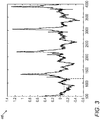
- Fig. 3 is a schematic view of an intracardiac (IC) signal 46 sampled in the system 20 of Fig. 1 .
- Respective IC signals 46 are received from respective electrodes 32 ( Fig. 1 ).
- Fig. 3 shows an example signal 46 received from the electrode 32-1 ( Fig. 2A ).
- Fig. 3 shows the signal 46 being sampled at 1200 milliseconds corresponding with a voltage of approximately -0.1 millivolts.
- the signals received from the other electrodes 32 are also sampled at 1200 milliseconds to find the voltage for the other electrodes 32.
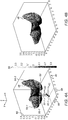
- FIG. 4A is a schematic view of a curved three-dimensional surface 48 describing electrical activity rendered by the system 10 of Fig. 1 .
- Fig. 4A shows some of the positions 42 of the electrodes 32 ( Fig. 2A ) projected on the plane 40 which is on the x-y axes 58.
- the position 42-1 of the electrode 32-1 ( Fig. 2A ) is shown on the plane 40.
- the sampled voltage of electrode 32-1 at time 1200 milliseconds is -0.1 millivolts, as illustrated in Fig. 3 .
- a data point 50-1 of the three-dimensional surface 48 is derived from the position 42-1 and the associated sample voltage of -0.1 volts.
- a displacement 52-1 of the data point 50-1 from the plane 40 in a direction perpendicular to the plane 40 is computed based on the sampled voltage of the electrode 32-1 at time 1200 milliseconds.
- respective data points 50 are computed based on respective projected positions 42 and the computed respective displacements 52.
- the three-dimensional surface 48 is fitted to data points 50 using any suitable surface fitting method, which may include interpolation and optionally extrapolation based on the data points 50.
- Fig. 4A shows the x-y axes 58 and the z-axis 60 being labeled with suitable units of displacement, and voltage, respectively.
- Regions 54 of the three-dimensional surface 48 have been colored with different colors according to the voltage values associated with the regions 54.
- region 54-1 may be red
- region 54-2 may be yellow
- Fig. 4A includes a legend 56 which provides a mapping between color and voltage values.
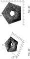
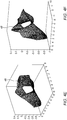
- Figs. 4B-F are schematic views of curved three-dimensional surfaces 48 describing electrical activity rendered by the system 10 of Fig. 1 .
- the three-dimensional surface 48 shown in Fig. 4B represents electrical activity over the electrodes 32 ( Fig. 2A ) at another sampling time, for example, at a sampling time of 1250 milliseconds.
- Fig. 4C shows more of the top of one of the three-dimensional surfaces 48.
- Fig. 4D shows one of the three-dimensional surfaces 48 directly from above so that the z-axis is not even visible.
- Figs. 4E and 4F are further examples of three-dimensional surfaces 48.
- Fig. 5 is a flow-chart 70 including steps in a method of operation of the system 10 of Fig. 1 .
- the catheter is inserted (block 72) into a chamber of the heart 12 ( Fig. 1 ) of the living subject.
- Respective catheter electrodes 32 ( Fig. 2A ) contact tissue at respective locations within the chamber of the heart 12. Some of the catheter electrodes 32 may be in contact with the tissue while other electrodes 32 are not in contact with the tissue. In some cases, all the electrodes 32 may be in contact with the tissue.
- the processing circuitry 22 ( Fig. 1 ) is configured to receive (block 74) signals 46 ( Fig. 3 ) from the catheter 14 ( Fig. 1 ), and in response to the signals 46, sample (block 76) voltage values of the signals 46 at respective sampling times, compute respective curved three-dimensional surfaces 48 ( Figs. 4A-F ), and render the three-dimensional surfaces 48 to the display 29. These steps are described in more detail below.
- the signal 46 of each electrode 32 is typically sampled at each of the respective sampling times.
- the processing circuitry is configured to sample the voltage values of the signals 46 at the respective sampling times at a rate exceeding ten times per second. In other embodiments, the sampling rate is less than, or equal to, ten times per second.
- the processing circuitry 22 is configured to compute (block 78) respective positions 42 ( Figs. 2A-B ) of the respective catheter electrodes 32, for example, responsively to at least one signal received from a position transducer (not shown), which may be part of the catheter and/or part of an external apparatus such as body patches or an external position sensor.
- a position transducer not shown
- the respective positions 42 of the respective catheter electrodes 32, used in the computations described below are respective positions 42 derived from a static computer model of the catheter 14.
- the respective positions 42 of the respective catheter electrodes 32 may be respective projected positions 42 projected onto the plane 40 ( Figs. 2A-B ). In some embodiments, the respective positions 42 of the respective catheter electrodes 32 are respective projected positions 42 projected onto the plane 40, which is perpendicular to the axis 45 of the shaft 44 ( Figs. 2A-B ).
- the processing circuitry 22 is configured to compute (block 80) respective curved three-dimensional surfaces 48 ( Figs. 4A-F ) describing electrical activity of the tissue over the catheter electrodes 32 at respective ones of the sampling times. It should be noted that any one of the three-dimensional surfaces 48 describes electrical activity for one of the sampling times and not multiple sampling times. The sampled voltages of different sampling times yield different three-dimensional surfaces 48.
- the three-dimensional surfaces 48 are computed responsively to: (a) respective positions 42 (e.g., represented by two-dimensional coordinates) of the respective catheter electrodes 32; and (b) the respective sampled voltage values indicative of electrical activity of the tissue that is sensed by the respective catheter electrodes 32 at the respective locations (on the tissue) at the respective sampling times.
- the processing circuitry 22 is configured to compute (block 82) respective displacements 52 ( Fig. 4A ), perpendicular to the plane 40 ( Fig. 4A ), from respective ones of the projected positions 42 of respective ones of the catheter electrodes 32 responsively to respective ones of the sampled voltage values at respective ones of the sampling times.
- the displacement 52 in the z-axis 60 ( Fig. 4A )) from the positions 42 (in the x-y axes 58 ( Fig. 4A )) define the data points 50 ( Fig. 4A ) having x,y,z coordinates.
- the processing circuitry 22 is configured to fit (block 84) the respective curved three-dimensional surfaces 48 describing the electrical activity of the tissue over the catheter electrodes 32 at the respective ones of the sampling times, responsively to respective ones of the displacements 52, perpendicular to the plane 40, from respective ones of the projected positions 42.
- the processing circuitry 22 is configured to fit the respective curved three-dimensional surfaces 48 describing the electrical activity of the tissue over the catheter electrodes 32 at the respective ones of the sampling times, responsively to respective ones of the data points 50 (e.g., having x,y,z coordinates).
- the processing circuitry 22 is configured to compute respective displacements 52 ( Fig. 4A ), perpendicular to the plane 40 ( Fig.
- the processing circuitry 22 is configured to render (block 86) the respective three-dimensional surfaces 48 to the display 29 ( Fig. 1 ) over time.
- the processing circuitry 22 is configured to render the respective three-dimensional surfaces 48 to the display 29 over time with a new one of the three-dimensional surfaces 48 (e.g., corresponding to a next sampling time) being displayed at least every tenth of a second so that the rendered three-dimensional surfaces 48 provide an animation of an activation wave associated with the electrical activity of the tissue over the catheter electrodes 32.
- the processing circuitry 22 is configured to render the respective three-dimensional surfaces 48 to the display 29 over time with a new one of the three-dimensional surfaces 48 being displayed at a rate less that every tenth of a second.
- the processing circuitry is configured to color (block 88) respective regions 54 ( Fig. 4A ) of the respective three-dimensional surfaces 48 responsively to respective ones of the sampled voltage values or respective ones of the displacements 52 ( Fig. 4A ).
- the interface 39 ( Fig. 1 ) is configured to receive (block 90) user input to change a viewing angle of ones of the three-dimensional surfaces 48.
- the processing circuitry 22 is configured to render (block 92) ones of the three-dimensional surfaces 48 with a different viewing angle responsively to the received user input.
- the terms “about” or “approximately” for any numerical values or ranges indicate a suitable dimensional tolerance that allows the part or collection of components to function for its intended purpose as described herein. More specifically, “about” or “approximately” may refer to the range of values ⁇ 20% of the recited value, e.g. "about 90%” may refer to the range of values from 71% to 99%.
Landscapes
- Health & Medical Sciences (AREA)
- Life Sciences & Earth Sciences (AREA)
- Engineering & Computer Science (AREA)
- Surgery (AREA)
- Medical Informatics (AREA)
- Public Health (AREA)
- Physics & Mathematics (AREA)
- General Health & Medical Sciences (AREA)
- Biomedical Technology (AREA)
- Molecular Biology (AREA)
- Animal Behavior & Ethology (AREA)
- Veterinary Medicine (AREA)
- Heart & Thoracic Surgery (AREA)
- Pathology (AREA)
- Biophysics (AREA)
- Cardiology (AREA)
- Nuclear Medicine, Radiotherapy & Molecular Imaging (AREA)
- Radiology & Medical Imaging (AREA)
- Plasma & Fusion (AREA)
- Otolaryngology (AREA)
- Physiology (AREA)
- Human Computer Interaction (AREA)
- Computer Graphics (AREA)
- General Physics & Mathematics (AREA)
- Theoretical Computer Science (AREA)
- Epidemiology (AREA)
- Primary Health Care (AREA)
- Measurement And Recording Of Electrical Phenomena And Electrical Characteristics Of The Living Body (AREA)
- Measuring And Recording Apparatus For Diagnosis (AREA)
Abstract
Description
- The present invention relates to medical systems, and in particular, but not exclusively, to analysis of electrical activity.
- Electrical activity at a point in the heart may be measured by advancing a multiple-electrode catheter to measure electrical activity at multiple points in the heart chamber simultaneously. Other methods, such as using an external vest may provide an indication of cardiac activity. A record derived from time varying electrical potentials as measured by one or more electrodes is known as an electrogram. Electrograms may be measured by unipolar or bipolar leads, and are used, e.g., to determine onset of electrical propagation at a point, known as local activation time (LAT).
-
US Patent 5,782,773 to Kuo, et al. , describes a three-dimensional electrocardiogram display method for 3-D representation of a plurality of cardiac signals. In this method, a 3-D rectangular coordinate system is defined to display the 3-D representation of the cardiac signals. Further, an amplitude display scheme, preferably an amplitude-to-color mapping table, is defined to assign various quantization levels of amplitude to specified distinctive colors. By graphic processing and display means, the 3-D representation of the cardiac signals can be generated and displayed. The physicians can choose to observe the 3-D graph in various views, including perspective view, sectional view, and top rectangular view. This allows the physicians to make diagnosis of heart diseases by observing just one or two 3-D representations of the cardiac signals. The physicians can thus have an overall integral view over a plentiful number of cardiac signals and thereby make diagnosis about the heart conditions of the patient more easily. -
US Patent Publication 2011/0021936 of Luo describes a device and method for displaying medical data for a stress test monitoring system. A computer-implemented method and apparatus for displaying electrical impulse data of a human heart for analysis includes receiving cardiac electrical impulse data produced during a cardiac stress test by a plurality of electrode leads adapted for placement on a patient and calculating parameters for a plurality of display windows based on the data and providing a main display in which the plurality of display windows are positioned. A three-dimensional color mapping plot is displayed in one of the plurality of display windows and a two dimensional color mapping plot is displayed in another of the plurality of display windows. Additionally, a plot of raw lead data from at least one lead is displayed in one of the plurality of display windows. -
US Patent Publication 2012/0130232 of Markowitz, et al. , describes a volume of a patient that can be mapped with a system operable to identify a plurality of locations and save a plurality of locations of a mapping instrument. The mapping instrument can include one or more electrodes that can sense a voltage that can be correlated to a three-dimensional location of the electrode at the time of the sensing or measurement. Therefore, a map of a volume can be determined based upon the sensing of the plurality of points without the use of other imaging devices. An implantable medical device can then be navigated relative to the mapping data. - International Patent Publication
WO 2017/192769 of Acutus Medical Inc., describes a localization system and method useful in the acquisition and analysis of cardiac information. The localization system and method can be used with systems that perform cardiac mapping, diagnosis and treatment of cardiac abnormalities, as examples, and in the retrieval, processing, and interpretation of such types of information. The localization system and method use high impedance inputs, improved isolation, and relatively high drive currents for pairs of electrodes used to establish a multi-axis coordinate system. The axes can be rotated and scaled to improve localization. - There is provided in accordance with an embodiment of the present disclosure, a medical system, including a catheter configured to be inserted into a chamber of a heart of a living subject, and including catheter electrodes configured to contact tissue at respective locations within the chamber of the heart, a display, and processing circuitry configured to receive signals from the catheter, and in response to the signals sample voltage values of the signals at respective sampling times, compute respective curved three-dimensional surfaces describing electrical activity of the tissue over the catheter electrodes at respective ones of the sampling times, responsively to (a) respective positions of the respective catheter electrodes, and (b) the respective sampled voltage values indicative of electrical activity of the tissue that is sensed by the respective catheter electrodes at the respective locations at the respective sampling times, and render the respective three-dimensional surfaces to the display over time.
- Further in accordance with an embodiment of the present disclosure the processing circuitry is configured to color respective regions of the respective three-dimensional surfaces responsively to respective ones of the sampled voltage values.
- Still further in accordance with an embodiment of the present disclosure the respective positions of the respective catheter electrodes are respective projected positions projected onto a plane, the processing circuitry is configured to compute respective displacements, perpendicular to the plane, from respective ones of the projected positions of respective ones of the catheter electrodes responsively to respective ones of the sampled voltage values at respective ones of the sampling times, and the processing circuitry is configured to fit the respective curved three-dimensional surfaces describing the electrical activity of the tissue over the catheter electrodes at the respective ones of the sampling times, responsively to respective ones of the displacements, perpendicular to the plane, from respective ones of the projected positions.
- Additionally, in accordance with an embodiment of the present disclosure the processing circuitry is configured to color respective regions of the respective three-dimensional surfaces responsively to respective ones of the displacements.
- Moreover, in accordance with an embodiment of the present disclosure the processing circuitry is configured to sample the voltage values of the signals at the respective sampling times at a rate exceeding ten times per second, and render the respective three-dimensional surfaces to the display over time with a new one of the three-dimensional surfaces being displayed at least every tenth of a second so that the rendered three-dimensional surfaces provide an animation of an activation wave associated with the electrical activity of the tissue over the catheter electrodes.
- Further in accordance with an embodiment of the present disclosure, the system includes an interface configured to receive user input to change a viewing angle of ones of the three-dimensional surfaces, wherein the processing circuitry is configured to render ones of the three-dimensional surfaces with a different viewing angle responsively to the received user input.
- Still further in accordance with an embodiment of the present disclosure the catheter includes a shaft having a distal end, and a distal end assembly on which the catheter electrodes are disposed, and the respective positions of the respective catheter electrodes are respective positions derived from a static computer model of the catheter.
- Additionally, in accordance with an embodiment of the present disclosure the respective positions of the respective catheter electrodes are respective projected positions projected onto a plane perpendicular to an axis of the shaft.
- Moreover, in accordance with an embodiment of the present disclosure the catheter includes a shaft having a distal end, and a distal end assembly on which the catheter electrodes are disposed, and the processing circuitry is configured to compute the respective positions of the respective catheter electrodes.
- Further in accordance with an embodiment of the present disclosure the respective positions of the respective catheter electrodes are respective projected positions projected onto a plane perpendicular to an axis of the shaft.
- There is also provided in accordance with another embodiment of the present disclosure a medical method, including receiving signals from a catheter, which is configured to be inserted into a chamber of a heart of a living subject, and including catheter electrodes configured to contact tissue at respective locations within the chamber of the heart, in response to the signals, sampling voltage values of the signals at respective sampling times, computing respective curved three-dimensional surfaces describing electrical activity of the tissue over the catheter electrodes at respective ones of the sampling times, responsively to (a) respective positions of the respective catheter electrodes, and (b) the respective sampled voltage values indicative of electrical activity of the tissue that is sensed by the respective catheter electrodes at the respective locations at the respective sampling times, and rendering the respective three-dimensional surfaces to a display over time.
- Still further in accordance with an embodiment of the present disclosure, the method includes coloring respective regions of the respective three-dimensional surfaces responsively to respective ones of the sampled voltage values.
- Additionally, in accordance with an embodiment of the present disclosure the respective positions of the respective catheter electrodes are respective projected positions projected onto a plane, the method further including computing respective displacements, perpendicular to the plane, from respective ones of the projected positions of respective ones of the catheter electrodes responsively to respective ones of the sampled voltage values at respective ones of the sampling times, and fitting the respective curved three-dimensional surfaces describing the electrical activity of the tissue over the catheter electrodes at the respective ones of the sampling times, responsively to respective ones of the displacements, perpendicular to the plane, from respective ones of the projected positions.
- Moreover, in accordance with an embodiment of the present disclosure, the method includes coloring respective regions of the respective three-dimensional surfaces responsively to respective ones of the displacements.
- Further in accordance with an embodiment of the present disclosure, the method includes sampling the voltage values of the signals at the respective sampling times at a rate exceeding ten times per second, wherein the rendering includes rendering the respective three-dimensional surfaces to the display over time with a new one of the three-dimensional surfaces being displayed at least every tenth of a second so that the rendered three-dimensional surfaces provide an animation of an activation wave associated with the electrical activity of the tissue over the catheter electrodes.
- Still further in accordance with an embodiment of the present disclosure, the method includes receiving user input to change a viewing angle of ones of the three-dimensional surfaces, and rendering ones of the three-dimensional surfaces with a different viewing angle responsively to the received user input.
- Additionally, in accordance with an embodiment of the present disclosure the catheter includes a shaft having a distal end, and a distal end assembly on which the catheter electrodes are disposed, and the respective positions of the respective catheter electrodes are respective positions derived from a static computer model of the catheter.
- Moreover, in accordance with an embodiment of the present disclosure the respective positions of the respective catheter electrodes are respective projected positions projected onto a plane perpendicular to an axis of the shaft.
- Further in accordance with an embodiment of the present disclosure the catheter includes a shaft having a distal end, and a distal end assembly on which the catheter electrodes are disposed, and the method further includes computing the respective positions of the respective catheter electrodes.
- Still further in accordance with an embodiment of the present disclosure the respective positions of the respective catheter electrodes are respective projected positions projected onto a plane perpendicular to an axis of the shaft.
- There is also provided in accordance with still another embodiment of the present disclosure a software product, including a non-transient computer-readable medium in which program instructions are stored, which instructions, when read by a central processing unit (CPU), cause the CPU to receive signals from a catheter, which is configured to be inserted into a chamber of a heart of a living subject, and including catheter electrodes configured to contact tissue at respective locations within the chamber of the heart, in response to the signals, sample voltage values of the signals at respective sampling times, compute respective curved three-dimensional surfaces describing electrical activity of the tissue over the catheter electrodes at respective ones of the sampling times, responsively to (a) respective positions of the respective catheter electrodes, and (b) the respective sampled voltage values indicative of electrical activity of the tissue that is sensed by the respective catheter electrodes at the respective locations at the respective sampling times, and render the respective three-dimensional surfaces to a display over time.
- The present invention will be understood from the following detailed description, taken in conjunction with the drawings in which:
-
Fig. 1 is a partly pictorial, partly block diagram view of a cardiac analysis system constructed and operative in accordance with an embodiment of the present invention; -
Figs. 2A-B are schematic view illustrating projecting positions of electrodes to a plane for use in the system ofFig. 1 ; -
Fig. 3 is a schematic view of an intracardiac signal sampled in the system ofFig. 1 ; -
Figs. 4A-F are schematic views of curved three-dimensional surfaces describing electrical activity rendered by the system ofFig. 1 ; and -
Fig. 5 is a flow-chart including steps in a method of operation of the system ofFig. 1 . - Presentation of electrical activity signals from complex multi spline catheters (e.g., a PENTARAY® catheter of Biosense Webster, Inc., Irvine, CA USA, or a basket catheter) or multi-electrodes on linear catheters in a way which is intuitive for the physician is challenging due to the geometric distribution of the electrodes. Presenting the electrical activity in a two-dimensional (2D) list, such as showing multiple intracardiac electrograms (IEGMs) does not reflect the geometry of the catheter.
- Embodiments of the present invention solve the above problems by providing a three-dimensional (3D) presentation including respective curved three-dimensional surfaces which describe electrical activity of tissue over catheter electrodes at respective sampling times.
- Intracardiac (IC) signals, which are received from the electrodes of a catheter are collected and sampled at different sampling times. The electrical activity of the catheter electrodes at one of the sampling times is plotted on the 3D presentation as a curved 3D surface. The 3D presentation may be defined by three axes (x, y and z) or any other suitable coordinate system. The x and y axes indicate the 2D position of the electrodes of the catheter (for example, by projecting the electrode position on to a plane defined by the x and y-axes). The z-axis indicates the voltage of the electrical activity captured by the electrodes at the sampled time. The curved 3D surface is computed by fitting the 3D surface to data points defined by the x-y coordinates of the electrode positions of the catheter electrodes and the respective z-coordinates of the sampled voltage. The fitting of the 3D surface may be performed by interpolating (and optionally extrapolating) between the data points mentioned above. Regions of the 3D surface may be optionally colored according to the voltage level associated with the regions.
- The 3D presentation may be static (e.g. for single sampling times) or may be dynamic (e.g., a video) showing how the electrical activity moves as an activation wave over the electrodes of the catheter providing the physician with a useful diagnostic tool.
- Any suitable catheter may be used in the above embodiments, for example, multi-spline catheters (e.g., a PENTARAY® catheter of Biosense Webster, Inc., Irvine, CA USA, or a basket catheter) or other multi-electrode catheters (e.g., balloon catheter, or Lasso catheter).
- The catheter is inserted into the heart chamber of a living subject. The catheter may include a shaft having a distal end, and a distal end assembly on which catheter electrodes are disposed. The catheter electrodes contact tissue at respective locations within the heart chamber. Processing circuitry receives signals from the catheter, and in response to the signals, samples voltage values of the signals at respective sampling times.
- In some embodiments, the processing circuitry computes respective positions of the respective catheter electrodes, for example, responsively to signal(s) received from a position transducer (such as a position sensor or sensors of the catheter or an externally placed sensor(s)).
- In other embodiments, the positions of the respective catheter electrodes, used in the computations described below, are derived from a static computer model of the catheter. For example, if the catheter being used is a multi-spline catheter with deflectable splines, the positions used in the computations described below may be based on the positions of the deflectable splines in a nondeflected position even if the splines are in fact deflected at the respective sampling time.
- Whether the positions are computed from the received signal(s) or derived from the static computer model, or any other suitable source, the positions of the catheter electrodes are typically projected positions projected onto a plane (e.g., the x-y axes described above). In some embodiments, the plane is perpendicular to an axis of the shaft of the catheter.
- The processing circuitry computes respective curved three-dimensional surfaces describing electrical activity of the tissue over the catheter electrodes at respective ones of the sampling times. It should be noted that any one of the three-dimensional surfaces describes electrical activity for a corresponding one of the sampling times and not multiple sampling times. The sampled voltages of different sampling times yield different three-dimensional surfaces. The three-dimensional surfaces are computed responsively to: (a) respective positions (e.g., two-dimensional position coordinates) of the respective catheter electrodes; and (b) the respective sampled voltage values indicative of electrical activity of the tissue that is sensed by the respective catheter electrodes at the respective locations (on the tissue) at the respective sampling times. For example, one three-dimensional surface is computed responsively to: (a) respective positions (e.g., two-dimensional position coordinates) of the respective catheter electrodes; and (b) the respective sampled voltage values sampled at one of the respective sampling times.
- In some embodiments, the processing circuitry colors respective regions of the respective three-dimensional surfaces responsively to respective ones of the sampled voltage values.
- In some embodiments, the processing circuitry computes respective displacements, perpendicular to the plane (e.g., along the z axis away from the x-y axes), from respective projected positions of respective catheter electrodes responsively to respective sampled voltage values at respective sampling times. Each displacement provides a z-axis coordinate when a cartesian coordinate system is used. For example, a displacement zn is computed according to the sampled voltage, sampled at time t1, of the signal sensed by electrode number n of the catheter. Electrode number n has position coordinates xn,yn on the plane defined by the x-y axes. Therefore, the data point of electrode number n in the 3D presentation for time t1 has coordinates xn,yn,zn. The processing circuitry fits the respective curved three-dimensional surfaces describing the electrical activity of the tissue over the catheter electrodes at the respective sampling times, responsively to the respective computed displacements, perpendicular to the plane, from respective ones of the projected positions, e.g., according to the data points representing the electrical activity of each of the electrodes in the coordinate system. In some embodiments, the processing circuitry colors respective regions of the respective three-dimensional surfaces responsively to respective ones of the displacements.
- The processing circuitry is configured to render the respective three-dimensional surfaces to the display over time. In some embodiments, the processing circuitry renders the respective three-dimensional surfaces to the display over time with a new one of the three-dimensional surfaces being displayed frequently enough (e.g., at least every one-tenth of a second) so that the rendered three-dimensional surfaces provide an animation of an activation wave associated with the electrical activity of the tissue over the catheter electrodes.
- A user interface may receive user input to change a viewing angle of the three-dimensional surfaces, which may then be rendered with a different viewing angle responsively to the received user input.
- Reference is now made to
Fig. 1 , which is a partly pictorial, partly block diagram view of acardiac analysis system 10 constructed and operative in accordance with an embodiment of the present invention. - Turning now to the drawings, reference is initially made to
Fig. 1 , which is a pictorial illustration of acardiac analysis system 10, constructed and operative in accordance with a disclosed embodiment of the invention, for computing and evaluating electrical activity and optionally for performing ablative procedures on aheart 12 of a living subject. The system comprises acatheter 14, such as a catheter, which is percutaneously inserted by anoperator 16 through the patient's vascular system into a chamber or vascular structure of theheart 12. Theoperator 16, who is typically a physician, brings adistal tip 18 of thecatheter 14 into contact with the heart wall, for example, at an ablation target site or to capture electrical potentials over time at multiple sample location over a surface of one or more chambers of theheart 12. Electrical activation maps may be prepared, according to the methods disclosed inU.S. Patents 6,226,542 ,6,301,496 , and6,892,091 . One commercial product embodying elements of thesystem 10 is available as the CARTO® 3 System, available from Biosense Webster, Inc. This system may be modified by those skilled in the art to embody the principles of the invention described herein. - Areas determined to be abnormal, for example by evaluation of the electrical activation maps, can be ablated by application of thermal energy, e.g., by passage of radiofrequency electrical current through wires in the catheter to one or more electrodes at the
distal tip 18, which apply the radiofrequency energy to the myocardium. The energy is absorbed in the tissue, heating it to a temperature (typically about 50°C) at which it permanently loses its electrical excitability. When successful, this procedure creates non-conducting lesions in the cardiac tissue, which disrupt the abnormal electrical pathway causing the arrhythmia. The principles of the invention can be applied to different heart chambers to diagnose and treat many different cardiac arrhythmias. - The
catheter 14 typically comprises ahandle 20, having suitable controls on the handle to enable theoperator 16 to steer, position and orient thedistal tip 18 of thecatheter 14 as desired for the ablation. To aid theoperator 16, a distal portion of thecatheter 14 contains position sensors (not shown) that provide signals to processingcircuitry 22, located in aconsole 24. Theprocessing circuitry 22 may fulfill several processing functions as described below. - Ablation energy and electrical signals can be conveyed to and from the
heart 12 throughcatheter electrodes 32 located at or near thedistal tip 18 viacable 34 to theconsole 24. In such a manner, theelectrodes 32 are configured to contact tissue at respective locations with the chamber of theheart 12 and capture electrical potentials over time at the respective locations. Additionally, or alternatively, other electrodes may be configured to capture electrical potentials over time at multiple sample locations over a surface of one or more chambers of theheart 12. Pacing signals and other control signals may be conveyed from theconsole 24 through thecable 34 and theelectrodes 32 to theheart 12. Thecatheter 14 may be implemented without ablation capabilities as an exploratory device having electrodes configured to capture electrical potentials over time at multiple sample locations over a surface of one or more chambers of theheart 12. -
Wire connections 35 link theconsole 24 withbody surface electrodes 30 and other components of a positioning sub-system for measuring location and orientation coordinates of thecatheter 14. Theprocessing circuitry 22 or another processor (not shown) may be an element of the positioning sub-system. Theelectrodes 32 and thebody surface electrodes 30 may be used to measure tissue impedance at the ablation site as taught inU.S. Patent 7,536,218 . A sensor for bioelectric information, e.g., a temperature sensor (not shown), typically a thermocouple or thermistor, may be mounted on or near each of theelectrodes 32. - The
console 24 typically contains one or moreablation power generators 25. Thecatheter 14 may be adapted to conduct ablative energy to the heart using any known ablation technique, e.g., radiofrequency energy, ultrasound energy, and laser-produced light energy. Such methods are disclosed inU.S. Patents 6,814,733 ,6,997,924 , and7,156,816 . - In one embodiment, the positioning subsystem comprises a magnetic position tracking arrangement that determines the position and orientation of the
catheter 14 by generating magnetic fields in a predefined working volume and sensing these fields at thecatheter 14, using field generating coils 28. The positioning subsystem is described inU.S. Patents 7,756,576 and7,536,218 . - As noted above, the
catheter 14 is coupled to theconsole 24, which enables theoperator 16 to observe and regulate the functions of thecatheter 14. Theprocessing circuitry 22 may be embodied as a computer with appropriate signal processing circuits. Theprocessing circuitry 22 is coupled to drive adisplay 29 including adisplay screen 37. The signal processing circuits may receive, amplify, filter and digitize signals from thecatheter 14, including signals generated by sensors such as electrical, temperature and contact force sensors, and location sensing electrodes (not shown) located distally in thecatheter 14. The digitized signals are received and used by theconsole 24 and the positioning sub-system to compute the position and orientation of thecatheter 14, and to analyze the electrical signals from the electrodes. - In order to generate electroanatomic maps, the
processing circuitry 22 typically comprises an electroanatomic map generator, an image registration program, an image or data analysis program and a graphical user interface configured to present graphical information on thedisplay 29. - In practice, some or all of these functions of the
processing circuitry 22 may be combined in a single physical component or, alternatively, implemented using multiple physical components. These physical components may comprise hard-wired or programmable devices, or a combination of the two. In some embodiments, at least some of the functions of the processing circuitry may be carried out by a programmable processor under the control of suitable software. This software may be downloaded to a device in electronic form, over a network, for example. Alternatively, or additionally, the software may be stored in tangible, non-transitory computer-readable storage media, such as optical, magnetic, or electronic memory. - The
console 24 may also include aninterface 39 to receive input commands from theoperator 16 via any suitable user input device, for example, but not limited to, a pointing device (such as a mouse of stylus), a keyboard, and/or a touch sensitive screen implemented in thedisplay screen 37. - Typically, the
system 10 includes other elements, which are not shown in the figures for the sake of simplicity. For example, thesystem 10 may include an electrocardiogram (ECG) monitor, coupled to receive signals from thebody surface electrodes 30, in order to provide an ECG synchronization signal to theconsole 24. As mentioned above, thesystem 10 typically also includes a reference position sensor, either on an externally applied reference patch attached to the exterior of the subject's body, or on an internally placed catheter, which is inserted into theheart 12 and maintained in a fixed position relative to theheart 12. Conventional pumps and lines for circulating liquids through thecatheter 14 for cooling the ablation site may be provided. Thesystem 10 may receive image data from an external imaging modality, such as an MRI unit or the like and includes image processors that can be incorporated in, or invoked by, theprocessing circuitry 22 for generating and displaying images. - Reference is now made to
Figs. 2A-B , which are schematic view illustrating projecting positions ofelectrodes 32 to aplane 40 for use in thesystem 10 ofFig. 1 . Thecatheter 14 shown inFig. 2A includes ashaft 44 having adistal end 62, and a distal end assembly 64 which comprises multiple splines with theelectrodes 32 disposed thereon. Any suitable distal end assembly may be used, for example, but not limited to, a basket distal end assembly, a balloon distal end assembly, or a lasso distal end assembly. -
Fig. 2A shows projecting electrodes 32-1 and 32-2 onto positions 42-1, 42-2, respectively, on theplane 40, by projecting in a direction which is perpendicular to theplane 40 and parallel to anaxis 45 of theshaft 44 of thecatheter 14. Theelectrodes 32 may be projected at any suitable direction on to theplane 40.Fig. 2B shows the projected positions 42 (only some labeled for the sake of simplicity) of all theelectrodes 32 of thecatheter 14. The position 42-1 of the electrodes 32-1 has coordinates x1,y1 in theplane 40, which is defined as lying on the x and y-axes. - Reference is now made to
Fig. 3 , which is a schematic view of an intracardiac (IC) signal 46 sampled in thesystem 20 ofFig. 1 . Respective IC signals 46 are received from respective electrodes 32 (Fig. 1 ).Fig. 3 shows anexample signal 46 received from the electrode 32-1 (Fig. 2A ).Fig. 3 shows thesignal 46 being sampled at 1200 milliseconds corresponding with a voltage of approximately -0.1 millivolts. Similarly, in this example, the signals received from theother electrodes 32 are also sampled at 1200 milliseconds to find the voltage for theother electrodes 32. - Reference is now made to
Fig. 4A , which is a schematic view of a curved three-dimensional surface 48 describing electrical activity rendered by thesystem 10 ofFig. 1 .Fig. 4A shows some of thepositions 42 of the electrodes 32 (Fig. 2A ) projected on theplane 40 which is on the x-y axes 58. For example, the position 42-1 of the electrode 32-1 (Fig. 2A ) is shown on theplane 40. The sampled voltage of electrode 32-1 at time 1200 milliseconds is -0.1 millivolts, as illustrated inFig. 3 . A data point 50-1 of the three-dimensional surface 48 is derived from the position 42-1 and the associated sample voltage of -0.1 volts. A displacement 52-1 of the data point 50-1 from theplane 40 in a direction perpendicular to the plane 40 (e.g., along the z-axis 60) is computed based on the sampled voltage of the electrode 32-1 at time 1200 milliseconds. Similarly, respective data points 50 (only some shown for the sake of simplicity) are computed based on respective projectedpositions 42 and the computedrespective displacements 52. The three-dimensional surface 48 is fitted todata points 50 using any suitable surface fitting method, which may include interpolation and optionally extrapolation based on the data points 50.Fig. 4A shows thex-y axes 58 and the z-axis 60 being labeled with suitable units of displacement, and voltage, respectively. - Regions 54 of the three-
dimensional surface 48 have been colored with different colors according to the voltage values associated with the regions 54. For example, region 54-1 may be red, while region 54-2 may be yellow.Fig. 4A includes alegend 56 which provides a mapping between color and voltage values. - Reference is now made to
Figs. 4B-F , which are schematic views of curved three-dimensional surfaces 48 describing electrical activity rendered by thesystem 10 ofFig. 1 . The three-dimensional surface 48 shown inFig. 4B represents electrical activity over the electrodes 32 (Fig. 2A ) at another sampling time, for example, at a sampling time of 1250 milliseconds.Fig. 4C shows more of the top of one of the three-dimensional surfaces 48.Fig. 4D shows one of the three-dimensional surfaces 48 directly from above so that the z-axis is not even visible.Figs. 4E and 4F are further examples of three-dimensional surfaces 48. - Reference is now made to
Fig. 5 , which is a flow-chart 70 including steps in a method of operation of thesystem 10 ofFig. 1 . - The catheter is inserted (block 72) into a chamber of the heart 12 (
Fig. 1 ) of the living subject. Respective catheter electrodes 32 (Fig. 2A ) contact tissue at respective locations within the chamber of theheart 12. Some of thecatheter electrodes 32 may be in contact with the tissue whileother electrodes 32 are not in contact with the tissue. In some cases, all theelectrodes 32 may be in contact with the tissue. - The processing circuitry 22 (
Fig. 1 ) is configured to receive (block 74) signals 46 (Fig. 3 ) from the catheter 14 (Fig. 1 ), and in response to thesignals 46, sample (block 76) voltage values of thesignals 46 at respective sampling times, compute respective curved three-dimensional surfaces 48 (Figs. 4A-F ), and render the three-dimensional surfaces 48 to thedisplay 29. These steps are described in more detail below. - The
signal 46 of eachelectrode 32 is typically sampled at each of the respective sampling times. In some embodiments, the processing circuitry is configured to sample the voltage values of thesignals 46 at the respective sampling times at a rate exceeding ten times per second. In other embodiments, the sampling rate is less than, or equal to, ten times per second. - In some embodiments, the
processing circuitry 22 is configured to compute (block 78) respective positions 42 (Figs. 2A-B ) of therespective catheter electrodes 32, for example, responsively to at least one signal received from a position transducer (not shown), which may be part of the catheter and/or part of an external apparatus such as body patches or an external position sensor. In other embodiments, therespective positions 42 of therespective catheter electrodes 32, used in the computations described below, arerespective positions 42 derived from a static computer model of thecatheter 14. - The
respective positions 42 of therespective catheter electrodes 32 may be respective projectedpositions 42 projected onto the plane 40 (Figs. 2A-B ). In some embodiments, therespective positions 42 of therespective catheter electrodes 32 are respective projectedpositions 42 projected onto theplane 40, which is perpendicular to theaxis 45 of the shaft 44 (Figs. 2A-B ). - The
processing circuitry 22 is configured to compute (block 80) respective curved three-dimensional surfaces 48 (Figs. 4A-F ) describing electrical activity of the tissue over thecatheter electrodes 32 at respective ones of the sampling times. It should be noted that any one of the three-dimensional surfaces 48 describes electrical activity for one of the sampling times and not multiple sampling times. The sampled voltages of different sampling times yield different three-dimensional surfaces 48. The three-dimensional surfaces 48 are computed responsively to: (a) respective positions 42 (e.g., represented by two-dimensional coordinates) of therespective catheter electrodes 32; and (b) the respective sampled voltage values indicative of electrical activity of the tissue that is sensed by therespective catheter electrodes 32 at the respective locations (on the tissue) at the respective sampling times. - In some embodiments, the
processing circuitry 22 is configured to compute (block 82) respective displacements 52 (Fig. 4A ), perpendicular to the plane 40 (Fig. 4A ), from respective ones of the projectedpositions 42 of respective ones of thecatheter electrodes 32 responsively to respective ones of the sampled voltage values at respective ones of the sampling times. The displacement 52 (in the z-axis 60 (Fig. 4A )) from the positions 42 (in the x-y axes 58 (Fig. 4A )) define the data points 50 (Fig. 4A ) having x,y,z coordinates. Theprocessing circuitry 22 is configured to fit (block 84) the respective curved three-dimensional surfaces 48 describing the electrical activity of the tissue over thecatheter electrodes 32 at the respective ones of the sampling times, responsively to respective ones of thedisplacements 52, perpendicular to theplane 40, from respective ones of the projected positions 42. In other words, theprocessing circuitry 22 is configured to fit the respective curved three-dimensional surfaces 48 describing the electrical activity of the tissue over thecatheter electrodes 32 at the respective ones of the sampling times, responsively to respective ones of the data points 50 (e.g., having x,y,z coordinates). For example, for one three-dimensional surface 48, theprocessing circuitry 22 is configured to compute respective displacements 52 (Fig. 4A ), perpendicular to the plane 40 (Fig. 4A ), from respective ones of the projectedpositions 42 of respective ones of thecatheter electrodes 32 responsively to respective ones of the sampled voltage values at one sampling time yieldingrespective data points 50, and fit that curved three-dimensional surface 48 describing the electrical activity of the tissue over thecatheter electrodes 32 at that sampling time, responsively to respective ones of the displacements 52 (i.e., the data points 50). - The
processing circuitry 22 is configured to render (block 86) the respective three-dimensional surfaces 48 to the display 29 (Fig. 1 ) over time. In some embodiments, theprocessing circuitry 22 is configured to render the respective three-dimensional surfaces 48 to thedisplay 29 over time with a new one of the three-dimensional surfaces 48 (e.g., corresponding to a next sampling time) being displayed at least every tenth of a second so that the rendered three-dimensional surfaces 48 provide an animation of an activation wave associated with the electrical activity of the tissue over thecatheter electrodes 32. In some embodiments, theprocessing circuitry 22 is configured to render the respective three-dimensional surfaces 48 to thedisplay 29 over time with a new one of the three-dimensional surfaces 48 being displayed at a rate less that every tenth of a second. - In some embodiments, the processing circuitry is configured to color (block 88) respective regions 54 (
Fig. 4A ) of the respective three-dimensional surfaces 48 responsively to respective ones of the sampled voltage values or respective ones of the displacements 52 (Fig. 4A ). - The interface 39 (
Fig. 1 ) is configured to receive (block 90) user input to change a viewing angle of ones of the three-dimensional surfaces 48. Theprocessing circuitry 22 is configured to render (block 92) ones of the three-dimensional surfaces 48 with a different viewing angle responsively to the received user input. - As used herein, the terms "about" or "approximately" for any numerical values or ranges indicate a suitable dimensional tolerance that allows the part or collection of components to function for its intended purpose as described herein. More specifically, "about" or "approximately" may refer to the range of values ±20% of the recited value, e.g. "about 90%" may refer to the range of values from 71% to 99%.
- Various features of the invention which are, for clarity, described in the contexts of separate embodiments may also be provided in combination in a single embodiment. Conversely, various features of the invention which are, for brevity, described in the context of a single embodiment may also be provided separately or in any suitable sub-combination.
- The embodiments described above are cited by way of example, and the present invention is not limited by what has been particularly shown and described hereinabove. Rather the scope of the invention includes both combinations and subcombinations of the various features described hereinabove, as well as variations and modifications thereof which would occur to persons skilled in the art upon reading the foregoing description and which are not disclosed in the prior art.
-
- 1. A medical method, comprising:
- receiving signals from a catheter, which is configured to be inserted into a chamber of a heart of a living subject, and including catheter electrodes configured to contact tissue at respective locations within the chamber of the heart;
- in response to the signals, sampling voltage values of the signals at respective sampling times;
- computing respective curved three-dimensional surfaces describing electrical activity of the tissue over the catheter electrodes at respective ones of the sampling times, responsively to: (a) respective positions of the respective catheter electrodes; and (b) the respective sampled voltage values indicative of electrical activity of the tissue that is sensed by the respective catheter electrodes at the respective locations at the respective sampling times; and
- rendering the respective three-dimensional surfaces to a display over time.
- 2. The method according to
aspect 1, further comprising coloring respective regions of the respective three-dimensional surfaces responsively to respective ones of the sampled voltage values. - 3. The method according to
aspect 1, wherein the respective positions of the respective catheter electrodes are respective projected positions projected onto a plane, the method further comprising:- computing respective displacements, perpendicular to the plane, from respective ones of the projected positions of respective ones of the catheter electrodes responsively to respective ones of the sampled voltage values at respective ones of the sampling times; and
- fitting the respective curved three-dimensional surfaces describing the electrical activity of the tissue over the catheter electrodes at the respective ones of the sampling times, responsively to respective ones of the displacements, perpendicular to the plane, from respective ones of the projected positions.
- 4. The method according to aspect 3, further comprising coloring respective regions of the respective three-dimensional surfaces responsively to respective ones of the displacements.
- 5. The method according to
aspect 1, further comprising sampling the voltage values of the signals at the respective sampling times at a rate exceeding ten times per second, wherein the rendering includes rendering the respective three-dimensional surfaces to the display over time with a new one of the three-dimensional surfaces being displayed at least every tenth of a second so that the rendered three-dimensional surfaces provide an animation of an activation wave associated with the electrical activity of the tissue over the catheter electrodes. - 6. The method according to
aspect 1, further comprising:- receiving user input to change a viewing angle of ones of the three-dimensional surfaces; and
- rendering ones of the three-dimensional surfaces with a different viewing angle responsively to the received user input.
- 7. The method according to
aspect 1, wherein:- the catheter comprises: a shaft having a distal end; and a distal end assembly on which the catheter electrodes are disposed; and
- the respective positions of the respective catheter electrodes are respective positions derived from a static computer model of the catheter.
- 8. The method according to aspect 7, wherein the respective positions of the respective catheter electrodes are respective projected positions projected onto a plane perpendicular to an axis of the shaft.
- 9. The method according to
aspect 1, wherein the catheter comprises: a shaft having a distal end; and a distal end assembly on which the catheter electrodes are disposed, and the method further comprises computing the respective positions of the respective catheter electrodes. - 10. The method according to aspect 9, wherein the respective positions of the respective catheter electrodes are respective projected positions projected onto a plane perpendicular to an axis of the shaft.
Claims (11)
- A medical system, comprising:a catheter configured to be inserted into a chamber of a heart of a living subject, and including catheter electrodes configured to contact tissue at respective locations within the chamber of the heart;a display; andprocessing circuitry configured to receive signals from the catheter, and in response to the signals:sample voltage values of the signals at respective sampling times;compute respective curved three-dimensional surfaces describing electrical activity of the tissue over the catheter electrodes at respective ones of the sampling times, responsively to: (a) respective positions of the respective catheter electrodes; and (b) the respective sampled voltage values indicative of electrical activity of the tissue that is sensed by the respective catheter electrodes at the respective locations at the respective sampling times; andrender the respective three-dimensional surfaces to the display over time.
- The system according to claim 1, wherein the processing circuitry is configured to color respective regions of the respective three-dimensional surfaces responsively to respective ones of the sampled voltage values.
- The system according to claim 1, wherein:the respective positions of the respective catheter electrodes are respective projected positions projected onto a plane;the processing circuitry is configured to compute respective displacements, perpendicular to the plane, from respective ones of the projected positions of respective ones of the catheter electrodes responsively to respective ones of the sampled voltage values at respective ones of the sampling times; andthe processing circuitry is configured to fit the respective curved three-dimensional surfaces describing the electrical activity of the tissue over the catheter electrodes at the respective ones of the sampling times, responsively to respective ones of the displacements, perpendicular to the plane, from respective ones of the projected positions.
- The system according to claim 3, wherein the processing circuitry is configured to color respective regions of the respective three-dimensional surfaces responsively to respective ones of the displacements.
- The system according to claim 1, wherein the processing circuitry is configured to:sample the voltage values of the signals at the respective sampling times at a rate exceeding ten times per second; andrender the respective three-dimensional surfaces to the display over time with a new one of the three-dimensional surfaces being displayed at least every tenth of a second so that the rendered three-dimensional surfaces provide an animation of an activation wave associated with the electrical activity of the tissue over the catheter electrodes.
- The system according to claim 1, further comprising an interface configured to receive user input to change a viewing angle of ones of the three-dimensional surfaces, wherein the processing circuitry is configured to render ones of the three-dimensional surfaces with a different viewing angle responsively to the received user input.
- The system according to claim 1, wherein:the catheter comprises: a shaft having a distal end; and a distal end assembly on which the catheter electrodes are disposed; andthe respective positions of the respective catheter electrodes are respective positions derived from a static computer model of the catheter.
- The system according to claim 7, wherein the respective positions of the respective catheter electrodes are respective projected positions projected onto a plane perpendicular to an axis of the shaft.
- The system according to claim 1, wherein:the catheter comprises: a shaft having a distal end; and a distal end assembly on which the catheter electrodes are disposed; andthe processing circuitry is configured to compute the respective positions of the respective catheter electrodes.
- The system according to claim 9, wherein the respective positions of the respective catheter electrodes are respective projected positions projected onto a plane perpendicular to an axis of the shaft.
- A software product, comprising a non-transient computer-readable medium in which program instructions are stored, which instructions, when read by a central processing unit (CPU), cause the CPU to:receive signals from a catheter, which is configured to be inserted into a chamber of a heart of a living subject, and including catheter electrodes configured to contact tissue at respective locations within the chamber of the heart;in response to the signals, sample voltage values of the signals at respective sampling times;compute respective curved three-dimensional surfaces describing electrical activity of the tissue over the catheter electrodes at respective ones of the sampling times, responsively to: (a) respective positions of the respective catheter electrodes; and (b) the respective sampled voltage values indicative of electrical activity of the tissue that is sensed by the respective catheter electrodes at the respective locations at the respective sampling times; andrender the respective three-dimensional surfaces to a display over time.
Applications Claiming Priority (1)
| Application Number | Priority Date | Filing Date | Title |
|---|---|---|---|
| US16/580,151 US12285258B2 (en) | 2019-09-24 | 2019-09-24 | 3D intracardiac activity presentation |
Publications (3)
| Publication Number | Publication Date |
|---|---|
| EP3797691A1 true EP3797691A1 (en) | 2021-03-31 |
| EP3797691C0 EP3797691C0 (en) | 2024-03-06 |
| EP3797691B1 EP3797691B1 (en) | 2024-03-06 |
Family
ID=72644050
Family Applications (1)
| Application Number | Title | Priority Date | Filing Date |
|---|---|---|---|
| EP20197871.5A Active EP3797691B1 (en) | 2019-09-24 | 2020-09-23 | 3d intracardiac activity presentation |
Country Status (7)
| Country | Link |
|---|---|
| US (1) | US12285258B2 (en) |
| EP (1) | EP3797691B1 (en) |
| JP (1) | JP7605396B2 (en) |
| KR (1) | KR20210036273A (en) |
| CN (1) | CN112617842B (en) |
| IL (1) | IL276664B2 (en) |
| RU (1) | RU2756369C1 (en) |
Families Citing this family (39)
| Publication number | Priority date | Publication date | Assignee | Title |
|---|---|---|---|---|
| US10905329B2 (en) | 2016-06-09 | 2021-02-02 | Biosense Webster (Israel) Ltd. | Multi-function conducting elements for a catheter |
| US12029545B2 (en) | 2017-05-30 | 2024-07-09 | Biosense Webster (Israel) Ltd. | Catheter splines as location sensors |
| US20190314083A1 (en) | 2018-04-11 | 2019-10-17 | Biosense Webster (Israel) Ltd. | Flexible Multi-Arm Catheter with Diametrically Opposed Sensing Electrodes |
| US11045628B2 (en) | 2018-12-11 | 2021-06-29 | Biosense Webster (Israel) Ltd. | Balloon catheter with high articulation |
| US11207016B2 (en) | 2018-12-28 | 2021-12-28 | Biosense Webster (Israel) Ltd. | Mapping ECG signals using a multipole electrode assembly |
| US11850051B2 (en) | 2019-04-30 | 2023-12-26 | Biosense Webster (Israel) Ltd. | Mapping grid with high density electrode array |
| US11712172B2 (en) | 2019-07-18 | 2023-08-01 | Biosense Webster (Israel) Ltd. | Visual guidance for positioning a distal end of a medical probe |
| US11759150B2 (en) | 2019-08-27 | 2023-09-19 | Biosense Webster (Israel) Ltd. | Accurate basket catheter tracking |
| US11950930B2 (en) | 2019-12-12 | 2024-04-09 | Biosense Webster (Israel) Ltd. | Multi-dimensional acquisition of bipolar signals from a catheter |
| US11517218B2 (en) | 2019-12-20 | 2022-12-06 | Biosense Webster (Israel) Ltd. | Selective graphical presentation of electrophysiological parameters |
| US12232874B2 (en) | 2020-05-29 | 2025-02-25 | Biosense Webster (Israel) Ltd. | Electrode apparatus for diagnosis of arrhythmias |
| US11987017B2 (en) | 2020-06-08 | 2024-05-21 | Biosense Webster (Israel) Ltd. | Features to assist in assembly and testing of devices |
| US12048479B2 (en) | 2020-09-10 | 2024-07-30 | Biosense Webster (Israel) Ltd. | Surface mounted electrode catheter |
| US11950841B2 (en) | 2020-09-22 | 2024-04-09 | Biosense Webster (Israel) Ltd. | Basket catheter having insulated ablation electrodes and diagnostic electrodes |
| US11950840B2 (en) | 2020-09-22 | 2024-04-09 | Biosense Webster (Israel) Ltd. | Basket catheter having insulated ablation electrodes |
| US12082875B2 (en) | 2020-09-24 | 2024-09-10 | Biosense Webster (Israel) Ltd | Balloon catheter having a coil for sensing tissue temperature and position of the balloon |
| US11974803B2 (en) | 2020-10-12 | 2024-05-07 | Biosense Webster (Israel) Ltd. | Basket catheter with balloon |
| US12201786B2 (en) | 2020-12-17 | 2025-01-21 | Biosense Webster (Israel) Ltd. | Measurement of distal end dimension of catheters using magnetic fields |
| US11918383B2 (en) | 2020-12-21 | 2024-03-05 | Biosense Webster (Israel) Ltd. | Visualizing performance of catheter electrodes |
| CN115250542A (en) * | 2021-04-25 | 2022-10-28 | 华为技术有限公司 | Communication method and device |
| US12064170B2 (en) | 2021-05-13 | 2024-08-20 | Biosense Webster (Israel) Ltd. | Distal assembly for catheter with lumens running along spines |
| CN117835929A (en) | 2021-08-10 | 2024-04-05 | 菲斯卡德公司 | Therapeutic system with sensing and ablation catheter for the treatment of cardiac rhythm disorders |
| US12364426B2 (en) | 2021-08-12 | 2025-07-22 | Biosense Webster (Israel) Ltd. | Electro-anatomical mapping and annotation presented in electrophysiological procedures |
| US12004804B2 (en) | 2021-09-09 | 2024-06-11 | Biosense Webster (Israel) Ltd. | Basket catheter with mushroom shape distal tip |
| US12478424B2 (en) | 2021-09-10 | 2025-11-25 | Biosense Webster (Israel) Ltd. | Staggered pairs of biased ablation electrodes on basket catheter |
| US12011280B2 (en) | 2021-10-04 | 2024-06-18 | Biosense Webster (Israel) Ltd. | Electrophysiological mapping in the presence of injury current |
| US12533489B2 (en) | 2021-10-08 | 2026-01-27 | Biosense Webster (Israel) Ltd. | Measuring tissue proximity for multi-electrode catheter |
| US11564591B1 (en) | 2021-11-29 | 2023-01-31 | Physcade, Inc. | System and method for diagnosing and treating biological rhythm disorders |
| US12419683B2 (en) | 2021-12-22 | 2025-09-23 | Biosense Webster (Israel) Ltd. | Irreversible electroporation with shorted electrodes |
| US12484961B2 (en) | 2022-01-20 | 2025-12-02 | Biosense Webster (Israel) Ltd. | Mechanical retainer systems for electrodes of a basket catheter, and methods of the same |
| US12440263B2 (en) | 2022-01-20 | 2025-10-14 | Biosense Webster (Israel) Ltd. | Systems and methods for tripodic spines forming a spherical basket for improved tissue contact and current delivery |
| US12446946B2 (en) | 2022-01-20 | 2025-10-21 | Biosense Webster (Israel) Ltd. | Systems and methods for a single spiral electrode assembly forming a spherical basket for improved tissue contact and current delivery |
| US12616517B2 (en) | 2022-03-25 | 2026-05-05 | Biosense Webster (Israel) Ltd. | Expandable basket assemblies with linear spine patterns for improved tissue contact and methods for making thereof |
| US12471989B2 (en) | 2022-04-28 | 2025-11-18 | Biosense Webster (Israel) Ltd. | Strengthened expandable baskets for medical probes and medical probes containing strengthen expandable baskets |
| US12616518B2 (en) | 2022-04-28 | 2026-05-05 | Biosense Webster (Israel) Ltd. | Barrel electrodes for a basket catheter, and methods of the same |
| US12616519B2 (en) | 2022-12-15 | 2026-05-05 | Biosense Webster (Israel) Ltd. | Basket assembly with atraumatic tip electrode and methods of making thereof |
| US12533185B2 (en) | 2022-12-28 | 2026-01-27 | Biosense Webster (Israel) Ltd. | Basket end effector with distal position sensor |
| US12521035B2 (en) | 2022-12-29 | 2026-01-13 | Biosense Webster (Israel) Ltd. | Cylindrical cage systems and methods for distributed tissue contact for mapping and ablation |
| US12290370B1 (en) * | 2024-01-19 | 2025-05-06 | Physcade, Inc. | System and method for mapping activation waves to guide treatment of biological rhythm disorders |
Citations (14)
| Publication number | Priority date | Publication date | Assignee | Title |
|---|---|---|---|---|
| US5782773A (en) | 1997-05-05 | 1998-07-21 | Chih-Wei Chen | Three-dimensional electrocardiogram display method |
| US6226542B1 (en) | 1998-07-24 | 2001-05-01 | Biosense, Inc. | Three-dimensional reconstruction of intrabody organs |
| US6301496B1 (en) | 1998-07-24 | 2001-10-09 | Biosense, Inc. | Vector mapping of three-dimensionally reconstructed intrabody organs and method of display |
| US6814733B2 (en) | 2002-01-31 | 2004-11-09 | Biosense, Inc. | Radio frequency pulmonary vein isolation |
| US6892091B1 (en) | 2000-02-18 | 2005-05-10 | Biosense, Inc. | Catheter, method and apparatus for generating an electrical map of a chamber of the heart |
| US6997924B2 (en) | 2002-09-17 | 2006-02-14 | Biosense Inc. | Laser pulmonary vein isolation |
| US7156816B2 (en) | 2002-11-26 | 2007-01-02 | Biosense, Inc. | Ultrasound pulmonary vein isolation |
| US7536218B2 (en) | 2005-07-15 | 2009-05-19 | Biosense Webster, Inc. | Hybrid magnetic-based and impedance-based position sensing |
| US7756576B2 (en) | 2005-08-26 | 2010-07-13 | Biosense Webster, Inc. | Position sensing and detection of skin impedance |
| US20110021936A1 (en) | 2009-07-24 | 2011-01-27 | Shen Luo | Medical data display with 3-D and 2-D color mapping |
| US20120130232A1 (en) | 2008-04-18 | 2012-05-24 | Regents Of The University Of Minnesota | Illustrating a Three-Dimensional Nature of a Data Set on a Two-Dimensional Display |
| US20150254893A1 (en) * | 2014-03-06 | 2015-09-10 | Boston Scientific Scimed, Inc. | Medical devices for mapping cardiac tissue and methods for displaying mapping data |
| WO2017192769A1 (en) | 2016-05-03 | 2017-11-09 | Acutus Medical, Inc. | Cardiac information dynamic display system and method |
| EP3375365A2 (en) * | 2017-03-17 | 2018-09-19 | Ablacon Inc. | Systems, devices, components and methods for detecting the locations of sources of cardiac rythm disorders in a patient's heart and classifying same |
Family Cites Families (21)
| Publication number | Priority date | Publication date | Assignee | Title |
|---|---|---|---|---|
| US5357428A (en) * | 1987-08-14 | 1994-10-18 | Micro-Tek, Inc. | Methods and apparatus for mapping electrophysiological potentials in living subjects |
| AU1459501A (en) * | 1999-11-05 | 2001-06-06 | Zynergy Cardiovascular (Zvc) Inc. | Cardiac mapping systems |
| DE102005005037B4 (en) * | 2005-02-03 | 2012-02-02 | Siemens Ag | Device for recording electrophysiological signals and for displaying the signals or signal information determined therefrom |
| US8494608B2 (en) * | 2008-04-18 | 2013-07-23 | Medtronic, Inc. | Method and apparatus for mapping a structure |
| RU2541126C2 (en) | 2009-03-26 | 2015-02-10 | Конинклейке Филипс Электроникс Н.В. | Perfusion imaging |
| US8355774B2 (en) * | 2009-10-30 | 2013-01-15 | Medtronic, Inc. | System and method to evaluate electrode position and spacing |
| US10441185B2 (en) * | 2009-12-16 | 2019-10-15 | The Board Of Trustees Of The University Of Illinois | Flexible and stretchable electronic systems for epidermal electronics |
| US10912476B2 (en) | 2013-01-16 | 2021-02-09 | University Of Vermont | Catheters, systems, and related methods for mapping, minimizing, and treating cardiac fibrillation |
| JP6422451B2 (en) | 2013-03-13 | 2018-11-14 | エフディーエヌエー インコーポレイテッド | System, method and computer-readable medium for identifying when a subject is likely to be affected by a medical condition |
| WO2014172524A1 (en) | 2013-04-18 | 2014-10-23 | St. Jude Medical, Atrial Fibrillation Division, Inc. | Systems and methods for visualizing and analyzing cardiac arrhythmias using 2-d planar projection and partially unfolded surface mapping processes |
| US9498147B2 (en) | 2014-01-30 | 2016-11-22 | Biosense Webster (Israel) Ltd. | Enhanced ECG chart presentation |
| EP3139830A4 (en) | 2014-05-05 | 2018-01-24 | Cardionxt, Inc. | Methods, systems, and apparatus for identification, characterization, and treatment of rotors associated with fibrillation |
| US9662033B2 (en) * | 2014-12-31 | 2017-05-30 | Biosense Webster (Israel) Ltd. | System and method for visualizing electrophysiology data |
| EP3346915A4 (en) | 2015-09-07 | 2018-10-10 | Ablacon Inc. | Systems, devices, components and methods for detecting the locations of sources of cardiac rhythm disorders in a patient's heart |
| US10588692B2 (en) * | 2015-11-06 | 2020-03-17 | Biosense Webster (Israel) Ltd. | Pulmonary vein isolation gap finder |
| US10136828B2 (en) | 2016-03-31 | 2018-11-27 | Biosense Webster (Israel) Ltd. | Mapping of atrial fibrillation |
| US10349855B2 (en) | 2016-06-10 | 2019-07-16 | Biosense Webster (Israel) Ltd. | Identification and visualization of cardiac activation sequence in multi-channel recordings |
| US10441188B2 (en) * | 2017-09-12 | 2019-10-15 | Biosense Webster (Israel) Ltd. | Automatic display of earliest LAT point |
| US11039776B2 (en) * | 2018-03-23 | 2021-06-22 | Cardioinsight Technologies, Inc. | Determining bipolar electrical activity |
| JP7488572B2 (en) * | 2018-04-30 | 2024-05-22 | ザ ボード オブ トラスティーズ オブ ザ レランド スタンフォード ジュニア ユニバーシティー | System and method for maintaining health using personal digital phenotypes |
| US20210118572A1 (en) * | 2018-06-14 | 2021-04-22 | St. Jude Medical, Cardiology Division, Inc. | System and Method for Mapping Cardiac Activity |
-
2019
- 2019-09-24 US US16/580,151 patent/US12285258B2/en active Active
-
2020
- 2020-08-11 IL IL276664A patent/IL276664B2/en unknown
- 2020-08-24 RU RU2020128012A patent/RU2756369C1/en active
- 2020-09-15 JP JP2020154335A patent/JP7605396B2/en active Active
- 2020-09-18 KR KR1020200120351A patent/KR20210036273A/en not_active Ceased
- 2020-09-23 EP EP20197871.5A patent/EP3797691B1/en active Active
- 2020-09-24 CN CN202011015600.7A patent/CN112617842B/en active Active
Patent Citations (14)
| Publication number | Priority date | Publication date | Assignee | Title |
|---|---|---|---|---|
| US5782773A (en) | 1997-05-05 | 1998-07-21 | Chih-Wei Chen | Three-dimensional electrocardiogram display method |
| US6226542B1 (en) | 1998-07-24 | 2001-05-01 | Biosense, Inc. | Three-dimensional reconstruction of intrabody organs |
| US6301496B1 (en) | 1998-07-24 | 2001-10-09 | Biosense, Inc. | Vector mapping of three-dimensionally reconstructed intrabody organs and method of display |
| US6892091B1 (en) | 2000-02-18 | 2005-05-10 | Biosense, Inc. | Catheter, method and apparatus for generating an electrical map of a chamber of the heart |
| US6814733B2 (en) | 2002-01-31 | 2004-11-09 | Biosense, Inc. | Radio frequency pulmonary vein isolation |
| US6997924B2 (en) | 2002-09-17 | 2006-02-14 | Biosense Inc. | Laser pulmonary vein isolation |
| US7156816B2 (en) | 2002-11-26 | 2007-01-02 | Biosense, Inc. | Ultrasound pulmonary vein isolation |
| US7536218B2 (en) | 2005-07-15 | 2009-05-19 | Biosense Webster, Inc. | Hybrid magnetic-based and impedance-based position sensing |
| US7756576B2 (en) | 2005-08-26 | 2010-07-13 | Biosense Webster, Inc. | Position sensing and detection of skin impedance |
| US20120130232A1 (en) | 2008-04-18 | 2012-05-24 | Regents Of The University Of Minnesota | Illustrating a Three-Dimensional Nature of a Data Set on a Two-Dimensional Display |
| US20110021936A1 (en) | 2009-07-24 | 2011-01-27 | Shen Luo | Medical data display with 3-D and 2-D color mapping |
| US20150254893A1 (en) * | 2014-03-06 | 2015-09-10 | Boston Scientific Scimed, Inc. | Medical devices for mapping cardiac tissue and methods for displaying mapping data |
| WO2017192769A1 (en) | 2016-05-03 | 2017-11-09 | Acutus Medical, Inc. | Cardiac information dynamic display system and method |
| EP3375365A2 (en) * | 2017-03-17 | 2018-09-19 | Ablacon Inc. | Systems, devices, components and methods for detecting the locations of sources of cardiac rythm disorders in a patient's heart and classifying same |
Also Published As
| Publication number | Publication date |
|---|---|
| JP7605396B2 (en) | 2024-12-24 |
| US12285258B2 (en) | 2025-04-29 |
| IL276664B1 (en) | 2024-06-01 |
| JP2021049334A (en) | 2021-04-01 |
| EP3797691C0 (en) | 2024-03-06 |
| CN112617842B (en) | 2025-09-26 |
| EP3797691B1 (en) | 2024-03-06 |
| IL276664A (en) | 2021-03-25 |
| CN112617842A (en) | 2021-04-09 |
| IL276664B2 (en) | 2024-10-01 |
| US20210085204A1 (en) | 2021-03-25 |
| KR20210036273A (en) | 2021-04-02 |
| RU2756369C1 (en) | 2021-09-29 |
Similar Documents
| Publication | Publication Date | Title |
|---|---|---|
| EP3797691B1 (en) | 3d intracardiac activity presentation | |
| AU2020200911B2 (en) | Registration maps using intra-cardiac signals | |
| JP7622162B2 (en) | Automatic display of the earliest LAT | |
| EP3449821B1 (en) | Advanced current location (acl) automatic map rotation to detect holes in current position map (cpm) mapping | |
| US20090177111A1 (en) | System and method for displaying contact between a catheter and tissue | |
| EP4183342A1 (en) | Mapping system with realtime electrogram overlay | |
| EP4122413A1 (en) | Accurate tissue proximity | |
| IL293219A (en) | Gesture based selection of portion of catheter | |
| EP3970613B1 (en) | Systems and methods for clustering wavefront signals in electrophysiological maps | |
| JP2025516867A (en) | Visualization of quality indicators indicating ablation stability at the ablation site | |
| EP4599768A1 (en) | Local ecg annotation visualization | |
| IL316849A (en) | Local ecg annotation visualization |
Legal Events
| Date | Code | Title | Description |
|---|---|---|---|
| PUAI | Public reference made under article 153(3) epc to a published international application that has entered the european phase |
Free format text: ORIGINAL CODE: 0009012 |
|
| STAA | Information on the status of an ep patent application or granted ep patent |
Free format text: STATUS: THE APPLICATION HAS BEEN PUBLISHED |
|
| AK | Designated contracting states |
Kind code of ref document: A1 Designated state(s): AL AT BE BG CH CY CZ DE DK EE ES FI FR GB GR HR HU IE IS IT LI LT LU LV MC MK MT NL NO PL PT RO RS SE SI SK SM TR |
|
| AX | Request for extension of the european patent |
Extension state: BA ME |
|
| STAA | Information on the status of an ep patent application or granted ep patent |
Free format text: STATUS: REQUEST FOR EXAMINATION WAS MADE |
|
| 17P | Request for examination filed |
Effective date: 20210923 |
|
| RBV | Designated contracting states (corrected) |
Designated state(s): AL AT BE BG CH CY CZ DE DK EE ES FI FR GB GR HR HU IE IS IT LI LT LU LV MC MK MT NL NO PL PT RO RS SE SI SK SM TR |
|
| RAP3 | Party data changed (applicant data changed or rights of an application transferred) |
Owner name: BIOSENSE WEBSTER (ISRAEL) LTD. |
|
| RIC1 | Information provided on ipc code assigned before grant |
Ipc: A61B 5/00 20060101ALI20230316BHEP Ipc: A61B 5/339 20210101AFI20230316BHEP |
|
| GRAP | Despatch of communication of intention to grant a patent |
Free format text: ORIGINAL CODE: EPIDOSNIGR1 |
|
| STAA | Information on the status of an ep patent application or granted ep patent |
Free format text: STATUS: GRANT OF PATENT IS INTENDED |
|
| INTG | Intention to grant announced |
Effective date: 20230424 |
|
| GRAJ | Information related to disapproval of communication of intention to grant by the applicant or resumption of examination proceedings by the epo deleted |
Free format text: ORIGINAL CODE: EPIDOSDIGR1 |
|
| STAA | Information on the status of an ep patent application or granted ep patent |
Free format text: STATUS: REQUEST FOR EXAMINATION WAS MADE |
|
| INTC | Intention to grant announced (deleted) | ||
| GRAP | Despatch of communication of intention to grant a patent |
Free format text: ORIGINAL CODE: EPIDOSNIGR1 |
|
| STAA | Information on the status of an ep patent application or granted ep patent |
Free format text: STATUS: GRANT OF PATENT IS INTENDED |
|
| INTG | Intention to grant announced |
Effective date: 20231011 |
|
| GRAS | Grant fee paid |
Free format text: ORIGINAL CODE: EPIDOSNIGR3 |
|
| GRAA | (expected) grant |
Free format text: ORIGINAL CODE: 0009210 |
|
| STAA | Information on the status of an ep patent application or granted ep patent |
Free format text: STATUS: THE PATENT HAS BEEN GRANTED |
|
| AK | Designated contracting states |
Kind code of ref document: B1 Designated state(s): AL AT BE BG CH CY CZ DE DK EE ES FI FR GB GR HR HU IE IS IT LI LT LU LV MC MK MT NL NO PL PT RO RS SE SI SK SM TR |
|
| REG | Reference to a national code |
Ref country code: CH Ref legal event code: EP |
|
| REG | Reference to a national code |
Ref country code: IE Ref legal event code: FG4D |
|
| REG | Reference to a national code |
Ref country code: DE Ref legal event code: R096 Ref document number: 602020026706 Country of ref document: DE |
|
| U01 | Request for unitary effect filed |
Effective date: 20240405 |
|
| U07 | Unitary effect registered |
Designated state(s): AT BE BG DE DK EE FI FR IT LT LU LV MT NL PT SE SI Effective date: 20240415 |
|
| PG25 | Lapsed in a contracting state [announced via postgrant information from national office to epo] |
Ref country code: GR Free format text: LAPSE BECAUSE OF FAILURE TO SUBMIT A TRANSLATION OF THE DESCRIPTION OR TO PAY THE FEE WITHIN THE PRESCRIBED TIME-LIMIT Effective date: 20240607 |
|
| PG25 | Lapsed in a contracting state [announced via postgrant information from national office to epo] |
Ref country code: RS Free format text: LAPSE BECAUSE OF FAILURE TO SUBMIT A TRANSLATION OF THE DESCRIPTION OR TO PAY THE FEE WITHIN THE PRESCRIBED TIME-LIMIT Effective date: 20240606 Ref country code: HR Free format text: LAPSE BECAUSE OF FAILURE TO SUBMIT A TRANSLATION OF THE DESCRIPTION OR TO PAY THE FEE WITHIN THE PRESCRIBED TIME-LIMIT Effective date: 20240306 |
|
| PG25 | Lapsed in a contracting state [announced via postgrant information from national office to epo] |
Ref country code: ES Free format text: LAPSE BECAUSE OF FAILURE TO SUBMIT A TRANSLATION OF THE DESCRIPTION OR TO PAY THE FEE WITHIN THE PRESCRIBED TIME-LIMIT Effective date: 20240306 |
|
| PG25 | Lapsed in a contracting state [announced via postgrant information from national office to epo] |
Ref country code: RS Free format text: LAPSE BECAUSE OF FAILURE TO SUBMIT A TRANSLATION OF THE DESCRIPTION OR TO PAY THE FEE WITHIN THE PRESCRIBED TIME-LIMIT Effective date: 20240606 Ref country code: NO Free format text: LAPSE BECAUSE OF FAILURE TO SUBMIT A TRANSLATION OF THE DESCRIPTION OR TO PAY THE FEE WITHIN THE PRESCRIBED TIME-LIMIT Effective date: 20240606 Ref country code: HR Free format text: LAPSE BECAUSE OF FAILURE TO SUBMIT A TRANSLATION OF THE DESCRIPTION OR TO PAY THE FEE WITHIN THE PRESCRIBED TIME-LIMIT Effective date: 20240306 Ref country code: GR Free format text: LAPSE BECAUSE OF FAILURE TO SUBMIT A TRANSLATION OF THE DESCRIPTION OR TO PAY THE FEE WITHIN THE PRESCRIBED TIME-LIMIT Effective date: 20240607 Ref country code: ES Free format text: LAPSE BECAUSE OF FAILURE TO SUBMIT A TRANSLATION OF THE DESCRIPTION OR TO PAY THE FEE WITHIN THE PRESCRIBED TIME-LIMIT Effective date: 20240306 |
|
| U20 | Renewal fee for the european patent with unitary effect paid |
Year of fee payment: 5 Effective date: 20240807 |
|
| PG25 | Lapsed in a contracting state [announced via postgrant information from national office to epo] |
Ref country code: IS Free format text: LAPSE BECAUSE OF FAILURE TO SUBMIT A TRANSLATION OF THE DESCRIPTION OR TO PAY THE FEE WITHIN THE PRESCRIBED TIME-LIMIT Effective date: 20240706 |
|
| PG25 | Lapsed in a contracting state [announced via postgrant information from national office to epo] |
Ref country code: SM Free format text: LAPSE BECAUSE OF FAILURE TO SUBMIT A TRANSLATION OF THE DESCRIPTION OR TO PAY THE FEE WITHIN THE PRESCRIBED TIME-LIMIT Effective date: 20240306 |
|
| PG25 | Lapsed in a contracting state [announced via postgrant information from national office to epo] |
Ref country code: CZ Free format text: LAPSE BECAUSE OF FAILURE TO SUBMIT A TRANSLATION OF THE DESCRIPTION OR TO PAY THE FEE WITHIN THE PRESCRIBED TIME-LIMIT Effective date: 20240306 |
|
| PG25 | Lapsed in a contracting state [announced via postgrant information from national office to epo] |
Ref country code: PL Free format text: LAPSE BECAUSE OF FAILURE TO SUBMIT A TRANSLATION OF THE DESCRIPTION OR TO PAY THE FEE WITHIN THE PRESCRIBED TIME-LIMIT Effective date: 20240306 |
|
| PG25 | Lapsed in a contracting state [announced via postgrant information from national office to epo] |
Ref country code: SK Free format text: LAPSE BECAUSE OF FAILURE TO SUBMIT A TRANSLATION OF THE DESCRIPTION OR TO PAY THE FEE WITHIN THE PRESCRIBED TIME-LIMIT Effective date: 20240306 |
|
| PG25 | Lapsed in a contracting state [announced via postgrant information from national office to epo] |
Ref country code: SM Free format text: LAPSE BECAUSE OF FAILURE TO SUBMIT A TRANSLATION OF THE DESCRIPTION OR TO PAY THE FEE WITHIN THE PRESCRIBED TIME-LIMIT Effective date: 20240306 Ref country code: SK Free format text: LAPSE BECAUSE OF FAILURE TO SUBMIT A TRANSLATION OF THE DESCRIPTION OR TO PAY THE FEE WITHIN THE PRESCRIBED TIME-LIMIT Effective date: 20240306 Ref country code: RO Free format text: LAPSE BECAUSE OF FAILURE TO SUBMIT A TRANSLATION OF THE DESCRIPTION OR TO PAY THE FEE WITHIN THE PRESCRIBED TIME-LIMIT Effective date: 20240306 Ref country code: PL Free format text: LAPSE BECAUSE OF FAILURE TO SUBMIT A TRANSLATION OF THE DESCRIPTION OR TO PAY THE FEE WITHIN THE PRESCRIBED TIME-LIMIT Effective date: 20240306 Ref country code: IS Free format text: LAPSE BECAUSE OF FAILURE TO SUBMIT A TRANSLATION OF THE DESCRIPTION OR TO PAY THE FEE WITHIN THE PRESCRIBED TIME-LIMIT Effective date: 20240706 Ref country code: CZ Free format text: LAPSE BECAUSE OF FAILURE TO SUBMIT A TRANSLATION OF THE DESCRIPTION OR TO PAY THE FEE WITHIN THE PRESCRIBED TIME-LIMIT Effective date: 20240306 |
|
| REG | Reference to a national code |
Ref country code: DE Ref legal event code: R097 Ref document number: 602020026706 Country of ref document: DE |
|
| PLBE | No opposition filed within time limit |
Free format text: ORIGINAL CODE: 0009261 |
|
| STAA | Information on the status of an ep patent application or granted ep patent |
Free format text: STATUS: NO OPPOSITION FILED WITHIN TIME LIMIT |
|
| 26N | No opposition filed |
Effective date: 20241209 |
|
| PG25 | Lapsed in a contracting state [announced via postgrant information from national office to epo] |
Ref country code: MC Free format text: LAPSE BECAUSE OF FAILURE TO SUBMIT A TRANSLATION OF THE DESCRIPTION OR TO PAY THE FEE WITHIN THE PRESCRIBED TIME-LIMIT Effective date: 20240306 |
|
| REG | Reference to a national code |
Ref country code: CH Ref legal event code: PL |
|
| PG25 | Lapsed in a contracting state [announced via postgrant information from national office to epo] |
Ref country code: CH Free format text: LAPSE BECAUSE OF NON-PAYMENT OF DUE FEES Effective date: 20240930 |
|
| PG25 | Lapsed in a contracting state [announced via postgrant information from national office to epo] |
Ref country code: IE Free format text: LAPSE BECAUSE OF NON-PAYMENT OF DUE FEES Effective date: 20240923 |
|
| U20 | Renewal fee for the european patent with unitary effect paid |
Year of fee payment: 6 Effective date: 20250807 |
|
| PGFP | Annual fee paid to national office [announced via postgrant information from national office to epo] |
Ref country code: GB Payment date: 20250731 Year of fee payment: 6 |
|
| PG25 | Lapsed in a contracting state [announced via postgrant information from national office to epo] |
Ref country code: CY Free format text: LAPSE BECAUSE OF FAILURE TO SUBMIT A TRANSLATION OF THE DESCRIPTION OR TO PAY THE FEE WITHIN THE PRESCRIBED TIME-LIMIT; INVALID AB INITIO Effective date: 20200923 |
|
| PG25 | Lapsed in a contracting state [announced via postgrant information from national office to epo] |
Ref country code: HU Free format text: LAPSE BECAUSE OF FAILURE TO SUBMIT A TRANSLATION OF THE DESCRIPTION OR TO PAY THE FEE WITHIN THE PRESCRIBED TIME-LIMIT; INVALID AB INITIO Effective date: 20200923 |