EP3797626A1 - Smart insole and balance enhancement device comprising the same - Google Patents
Smart insole and balance enhancement device comprising the same Download PDFInfo
- Publication number
- EP3797626A1 EP3797626A1 EP20198153.7A EP20198153A EP3797626A1 EP 3797626 A1 EP3797626 A1 EP 3797626A1 EP 20198153 A EP20198153 A EP 20198153A EP 3797626 A1 EP3797626 A1 EP 3797626A1
- Authority
- EP
- European Patent Office
- Prior art keywords
- vibrator
- cop
- setting point
- controller
- vibrators
- Prior art date
- Legal status (The legal status is an assumption and is not a legal conclusion. Google has not performed a legal analysis and makes no representation as to the accuracy of the status listed.)
- Granted
Links
Images





Classifications
-
- A—HUMAN NECESSITIES
- A43—FOOTWEAR
- A43B—CHARACTERISTIC FEATURES OF FOOTWEAR; PARTS OF FOOTWEAR
- A43B7/00—Footwear with health or hygienic arrangements
- A43B7/14—Footwear with health or hygienic arrangements with foot-supporting parts
- A43B7/24—Insertions or other supports preventing the foot canting to one side , preventing supination or pronation
-
- A—HUMAN NECESSITIES
- A43—FOOTWEAR
- A43B—CHARACTERISTIC FEATURES OF FOOTWEAR; PARTS OF FOOTWEAR
- A43B17/00—Insoles for insertion, e.g. footbeds or inlays, for attachment to the shoe after the upper has been joined
-
- A—HUMAN NECESSITIES
- A43—FOOTWEAR
- A43B—CHARACTERISTIC FEATURES OF FOOTWEAR; PARTS OF FOOTWEAR
- A43B13/00—Soles; Sole-and-heel integral units
- A43B13/14—Soles; Sole-and-heel integral units characterised by the constructive form
-
- A—HUMAN NECESSITIES
- A43—FOOTWEAR
- A43B—CHARACTERISTIC FEATURES OF FOOTWEAR; PARTS OF FOOTWEAR
- A43B3/00—Footwear characterised by the shape or the use
- A43B3/34—Footwear characterised by the shape or the use with electrical or electronic arrangements
-
- A—HUMAN NECESSITIES
- A43—FOOTWEAR
- A43B—CHARACTERISTIC FEATURES OF FOOTWEAR; PARTS OF FOOTWEAR
- A43B3/00—Footwear characterised by the shape or the use
- A43B3/34—Footwear characterised by the shape or the use with electrical or electronic arrangements
- A43B3/38—Footwear characterised by the shape or the use with electrical or electronic arrangements with power sources
-
- A—HUMAN NECESSITIES
- A43—FOOTWEAR
- A43B—CHARACTERISTIC FEATURES OF FOOTWEAR; PARTS OF FOOTWEAR
- A43B7/00—Footwear with health or hygienic arrangements
- A43B7/14—Footwear with health or hygienic arrangements with foot-supporting parts
- A43B7/1405—Footwear with health or hygienic arrangements with foot-supporting parts with pads or holes on one or more locations, or having an anatomical or curved form
- A43B7/1415—Footwear with health or hygienic arrangements with foot-supporting parts with pads or holes on one or more locations, or having an anatomical or curved form characterised by the location under the foot
-
- A—HUMAN NECESSITIES
- A43—FOOTWEAR
- A43B—CHARACTERISTIC FEATURES OF FOOTWEAR; PARTS OF FOOTWEAR
- A43B7/00—Footwear with health or hygienic arrangements
- A43B7/14—Footwear with health or hygienic arrangements with foot-supporting parts
- A43B7/1405—Footwear with health or hygienic arrangements with foot-supporting parts with pads or holes on one or more locations, or having an anatomical or curved form
- A43B7/1455—Footwear with health or hygienic arrangements with foot-supporting parts with pads or holes on one or more locations, or having an anatomical or curved form with special properties
-
- A—HUMAN NECESSITIES
- A61—MEDICAL OR VETERINARY SCIENCE; HYGIENE
- A61B—DIAGNOSIS; SURGERY; IDENTIFICATION
- A61B5/00—Measuring for diagnostic purposes; Identification of persons
- A61B5/103—Measuring devices for testing the shape, pattern, colour, size or movement of the body or parts thereof, for diagnostic purposes
- A61B5/1036—Measuring load distribution, e.g. podologic studies
- A61B5/1038—Measuring plantar pressure during gait
-
- A—HUMAN NECESSITIES
- A61—MEDICAL OR VETERINARY SCIENCE; HYGIENE
- A61B—DIAGNOSIS; SURGERY; IDENTIFICATION
- A61B5/00—Measuring for diagnostic purposes; Identification of persons
- A61B5/103—Measuring devices for testing the shape, pattern, colour, size or movement of the body or parts thereof, for diagnostic purposes
- A61B5/11—Measuring movement of the entire body or parts thereof, e.g. head or hand tremor or mobility of a limb
- A61B5/112—Gait analysis
-
- G—PHYSICS
- G08—SIGNALLING
- G08B—SIGNALLING SYSTEMS, e.g. PERSONAL CALLING SYSTEMS; ORDER TELEGRAPHS; ALARM SYSTEMS
- G08B21/00—Alarms responsive to a single specified undesired or abnormal condition and not otherwise provided for
- G08B21/18—Status alarms
-
- G—PHYSICS
- G08—SIGNALLING
- G08B—SIGNALLING SYSTEMS, e.g. PERSONAL CALLING SYSTEMS; ORDER TELEGRAPHS; ALARM SYSTEMS
- G08B6/00—Tactile signalling systems, e.g. tactile personal calling systems
-
- A—HUMAN NECESSITIES
- A61—MEDICAL OR VETERINARY SCIENCE; HYGIENE
- A61B—DIAGNOSIS; SURGERY; IDENTIFICATION
- A61B5/00—Measuring for diagnostic purposes; Identification of persons
- A61B5/68—Arrangements of detecting, measuring or recording means, e.g. sensors, in relation to patient
- A61B5/6801—Arrangements of detecting, measuring or recording means, e.g. sensors, in relation to patient specially adapted to be attached to or worn on the body surface
- A61B5/6802—Sensor mounted on worn items
- A61B5/6804—Garments; Clothes
- A61B5/6807—Footwear
Definitions
- Some example embodiments relate to a smart insole and/or a balance enhancement device including the smart insole.
- a user wears shoes in daily life to protect feet of the user comfortably and safely.
- wearable devices are developed to detect a gait pattern of the user and to assist the user to stably walk by providing a sensor and/or an actuator to a shoe.
- Some example embodiments relate to a smart insole configured to be worn by a user.
- the smart insole may include a support layer; a plurality of pressure sensors associated with the support layer, the plurality of pressure sensors configured to sense a pressure applied thereto by a foot of the user; a plurality of vibrators associated with the support layer, the plurality of vibrators configured to generate a vibration; and a controller configured to, determine a center of pressure (COP) of the foot of the user based on the pressure sensed by each of the plurality of pressure sensors, and control the plurality of vibrators based on a positional relationship between a setting point and the COP.
- COP center of pressure
- the plurality of vibrators is configured to generate the vibration such that an intensity of the vibration is less than a threshold of a sole of the foot of the user.
- the controller is configured to control the plurality of vibrators based on information on at least one of a distance from the COP to the setting point and a direction from the COP toward the setting point.
- the controller is configured to control the plurality of vibrators such that, among the plurality of vibrators, an intensity of the vibration rearward of the setting point is greater than that of an intensity of the vibration provided forward of the setting point, in response to the controller determining that the COP is in front of the setting point.
- the controller is configured to control the plurality of vibrators such that ones of the plurality of vibrators rearward of the setting point vibrate and ones of the plurality of vibrators forward of the setting point do not vibrate, in response to the controller determining that the COP is in front of the setting point.
- the controller is configured to, determine whether a distance from a first auxiliary line to the COP is greater than or equal to a first threshold distance, the first auxiliary line being perpendicular to a longitudinal direction of the support layer and intersecting the setting point, and determine that the COP is positioned at the front of the setting point, if the distance from the first auxiliary line to the COP is greater than or equal to the first threshold distance and the COP is positioned at the front of the setting point.
- the controller is configured to control the plurality of vibrators such that, among the plurality of vibrators, an intensity of the vibration on a right side of the setting point is greater than an intensity of the vibration on a left side of the setting point, in response to the controller determining that the COP is on the left side of the setting point.
- the controller is configured to control the plurality of vibrators such that ones of the plurality of vibrators on the right side of the setting point vibrate and ones of the plurality of vibrators on the left side of the setting point do not vibrate, in response to the controller determining that the COP is on the left side of the setting point.
- the controller is configured to, determine whether a distance from a second auxiliary line is greater than or equal to a second setting threshold, the second auxiliary line being parallel to a longitudinal direction of the support layer and intersecting the setting point to the COP, and determine that the COP is positioned on the left side of the setting point, if the distance from the second auxiliary line is greater than or equal to the second setting threshold and the COP is positioned at the left of the setting point.
- the plurality of vibrators include a front vibrator configured to apply a vibration to a forefoot of the user; and a rear vibrator configured to apply a vibration to a rearfoot of the user.
- the controller is configured to vibrate one or more of the front vibrator and the rear vibrator based on the positional relationship between the setting point and the COP.
- the front vibrator includes a right front vibrator and a left front vibrator that are aligned in a width direction of the support layer, and wherein the controller is configured to control plurality of vibrators such that the right front vibrator vibrates and the left front vibrator does not vibrate, in response to the controller determining that the COP is positioned on a left side of the setting point.
- the smart insole further includes a base configured to support the support layer; and a cover detachably provided to the base, wherein the support layer is provided between the base and the cover.
- Some example embodiments relate to a smart insole configured to be worn by a user.
- the smart insole includes a support layer; a plurality of pressure sensors associated with the support layer, the plurality of pressure sensors configured to sense a pressure applied thereto by a foot of the user; a plurality of vibrators associated with the support layer, the plurality of vibrators configured to generate a vibration having an intensity less than a threshold of a sole of the foot of the user; and a controller configured to, determine a center of pressure (COP) of the foot of the user based on the pressure sensed by each of the plurality of pressure sensors, determine whether the user is in an abnormal condition of balance based on a positional relationship between a setting point and the COP, and control the plurality of vibrators such that the intensity of the vibration is different in at least a portion of the plurality of vibrators.
- COP center of pressure
- the controller is configured to, determine that the user is in the abnormal condition of balance in response to the controller determining that the COP is in front of or behind the setting point, and control the plurality of vibrators such that, among the plurality of vibrators, the intensity of the vibration forward of the setting point differs from the intensity of the vibration rearward of the setting point, in response to the controller determining that the COP is in front of or behind the setting point.
- the controller is configured to, determine that the user is in the abnormal condition of balance in response to the controller determining that the COP is on a left side or on a right side of the setting point, and control the plurality of vibrators such that, among the plurality of vibrators, the intensity of the vibration on the left side of the setting point differs from the intensity of the vibration on the right side of the setting point in response to the controller determining that the COP is on the left side or on the right side of the setting point.
- Some example embodiments relate to a balance enhancement device.
- the balance enhancement device may include a left smart insole including a left support layer configured to support a left foot of a user, the left support layer having at least one left pressure sensor and at least one left vibrator associated therewith; a right smart insole including a right support layer configured to support a right foot of the user, the right support layer having at least one right pressure sensor and at least one right vibrator associated therewith; and a controller configured to control the at least one left vibrator and the at least one right vibrator such that an intensity of a vibration generated thereby differs based on a pressure value measured by the left pressure sensor and the right pressure sensor.
- the controller is configured to control the at least one left vibrator and the at least one right vibrator such that the intensity of the vibration of the at least one right vibrator is greater the intensity of the vibration of the at least one left vibrator, in response to the controller determining that the pressure value measured by the at least one left pressure sensor is greater than the pressure value measured by the at least one right pressure sensor.
- the controller is configured to control the at least one left vibrator and the at least one right vibrator such that the at least one right vibrator vibrates and the left at least one vibrator does not vibrate, in response to the controller determining that the pressure value measured by the left pressure sensor is greater than the pressure value measured by the right pressure sensor.
- the at least one left vibrator and the at least one right vibrator are configured to generate the vibration such that the intensity of the vibration is less than a threshold of a sole of the user.
- first, second, A, B, (a), (b), and the like may be used herein to describe components.
- Each of these terminologies is not used to define an essence, order or sequence of a corresponding component but used merely to distinguish the corresponding component from other component(s). It should be noted that if it is described in the specification that one component is “connected”, “coupled”, or “joined” to another component, a third component may be “connected”, “coupled”, and “joined” between the first and second components, although the first component may be directly connected, coupled or joined to the second component.
- a component including a common function with a component in one example embodiment is described using the same term in another example embodiment. Unless the context clearly indicates otherwise, description made in one example embodiment may apply to another example embodiment and repetitive description is omitted.
- FIG. 1 is a side view of a smart shoe according to at least one example embodiment
- FIG. 2 is a top view illustrating a smart insole according to at least one example embodiment
- FIG. 3 is a cross-sectional view illustrating the smart insole cut along line III-III of FIG. 2
- FIG. 4 is a top view illustrating a smart insole from which a cover is separated according to at least one example embodiment.
- a smart shoe 100 may include a smart insole 1, a midsole 91, and an upper 92.
- the smart shoe 100 may sense pressure applied from a foot of a user using a plurality of pressure sensors 141 and 142 provided to the smart insole 1, and may verify a center of pressure (COP) of a sole of the user.
- the smart shoe 100 may apply a vibration to the sole of the user using a plurality of vibrators 151 and 152 provided to the smart insole 1.
- the plurality of vibrators 151 and 152 may apply the vibration to a forefoot and/or rearfoot of the sole of the user.
- a longitudinal direction of the smart shoe 100 denotes a y-axial direction
- a widthwise direction of the smart shoe 100 denotes an x-axial direction
- a height direction of the smart shoe 100 denotes a z-axial direction.
- front denotes +y direction
- rear denotes -y direction in a coordinate system of FIG. 1 , unless the context clearly indicates otherwise.
- the smart insole 1 may sense the pressure applied from the sole of the user and may apply an appropriate stimulus to the sole of the user, thereby enhancing balance of the user. For example, if the COP of the sole of the user is too far forward, the smart insole 1 may enhance a sensitivity of the rearfoot of the user by applying a vibration to a rear portion of the sole of the user, that is, the rearfoot of the user to cause the COP of the sole of the user move backward. For example, a stimulus applied by the smart insole 1 to the user may be less than or equal to a threshold.
- the smart insole 1 may include a surface in contact with the sole of the user and may support the foot of the user.
- the smart insole 1, aside from an electronic device, for example, the pressure sensors 141 and 142 and/or the vibrators 151 and 152, provided therein, may be formed of a flexible material to enhance a fitting sense of the user.
- the smart insole 1 may insert inward into the upper 92 or may separate from the upper 92 through an opening provided in an upper portion of the upper 92.
- the smart insole 1 may be provided on a floor of the upper 92. If the upper 92 does not include the floor, the smart insole 1 may be provided on a top surface of the midsole 91.
- the smart insole 1 is described as one component of the smart shoe 100, it is provided as an example only.
- the smart insole 1 may insert into a sock and may perform a pressure measurement and a vibration application, thereby enhancing the balance of the user.
- the smart insole 1 may apply to various wearable devices, for example, a motion assist robot.
- the smart insole 1 may include a base 11, a cover 12, a support layer 13, the plurality of pressure sensors 141 and 142, the plurality of vibrators 151 and 152, a controller 16, an insert 17, and a connection line 19.
- the base 11 and the cover 12 may be combined with each other or may be separated from each other.
- the user may separate the cover 12 and may clean and/or replace the cover 12.
- Electronic elements provided in the smart insole 1, for example, the plurality of pressure sensors 141 and 142, the plurality of vibrators 151 and 152, and the controller 16 may be provided to the base 11.
- the cover 12 may not include any of the electronic elements.
- the cover 12 makes a direct contact with the sole of the user.
- the cover 12 may be relatively easily contaminated compared to the base 11 that makes an indirect contact with the sole of the user.
- the user may separate and clean only the cover 12. In this manner, the smart shoe 100 may be maintained to be in a hygienically excellent state.
- the base 11 may have a shape corresponding to an internal space of the upper 92.
- the base 11 may insert inward into the upper 92 through the opening provided in the upper portion of the upper 92.
- the base 11 may include a base protrusion 11a configured to enhance a combining force with the cover 12 and a base hole 11b configured to guide the connection line 19 to the controller 16.
- the base protrusion 11a may protrude upward, may insert into the cover 12, and may support the cover 12 such that the cover 12 does not move relative to the base 11.
- the base protrusion 11a may be fitted to the cover 12.
- the expression "fit” may inclusively indicate tight fit and any mutual coupling methods capable of reducing a phenomenon that the cover 12 slides relative to the base 11.
- the cover 12 may include a groove (not shown) recessed from a bottom surface of the cover 12, and the base protrusion 11a may insert into the groove.
- the base protrusion 11a may prevent the cover 12 from sliding in a horizontal direction, for example, the x-axial direction or the y-axial direction.
- the base protrusion 11a may surround the support layer 13 and may fasten the support layer 13.
- the base protrusion 11a is illustrated in a shape of a closed curve, it is provided as an example only.
- the base protrusion 11a may be in a shape including a plurality of unit bodies.
- the base hole 11b may be formed to vertically penetrate the base 11.
- the base hole 11b may be formed in a direction perpendicular to the smart insole 1, that is, the z-axial direction.
- the base hole 11b may function as a path that guides the connection line 19 from the top surface to the bottom surface of the base 11.
- the connection line 19 that passes through the base hole 11b may be connected to the controller 16.
- the plurality of pressure sensors 141 and 142 and the plurality of vibrators 151 and 152 may be provided to be close to the foot of the user and the effect from the pressure applied from the foot of the user against the controller 16 may decrease, thereby enhancing the durability of the controller 16.
- the base hole 11b may be formed in a space in which the plurality of pressure sensors 141 and 142 and the plurality of vibrators 151 and 152 are absent. That is, the base hole 11b may be formed in a portion that overlaps a midfoot.
- the pressure that applies to the base hole 11b and the connection line 19 passing the base hole 11b may relatively decrease and a disconnection risk of the connection line 19 may also decrease accordingly.
- a relatively strong pressure may apply to a portion that overlaps a forefoot, that is, the pressure sensor 141 and the vibrator 151 provided in a front portion of the smart insole 1.
- a relatively strong pressure may apply to a portion that overlaps a rearfoot, that is, the pressure sensor 142 and the vibrator 152 provided in a rear portion of the smart insole 1.
- a relatively small pressure may apply to a portion that overlaps a middle portion of the smart insole 1, that is, around the base hole 11b.
- the cover 12 is detachably provided to the base 11.
- the cover 12 may cover the plurality of pressure sensors 141 and 142 and the plurality of vibrators 151 and 152 to prevent the plurality of pressure sensors 141 and 142 and the plurality of vibrators 151 and 152 from making a direct contact with the foot of the user.
- a shape of the cover 12 may be approximately similar to a shape of the base 11.
- the cover 12 may mostly overlap the base 11 based on a vertical direction of the smart insole 1. For example, an electronic part may not be provided in the cover 12. According to the above structure, the user may separate and thereby clean or replace the cover 12 alone.
- the cover 12 in a shape customized for a shape of the foot of the user may be provided. Accordingly, cost and effort used to manufacture the smart shoe 100 may be saved.
- the support layer 13 may support the plurality of pressure sensors 141 and 142 and the plurality of vibrators 151 and 152, and may insert inward into the base protrusion 11a.
- the support layer 13 may be fitted to the base protrusion 11a.
- the support layer 13 may be tightly fastened inside the base protrusion 11a.
- the support layer 13 may be formed of a flexible film.
- the plurality of pressure sensors 141 and 142 may sense the pressure applied from the sole of the user.
- the plurality of pressure sensors 141 and 142 may be a pressure sensor, such as, for example, a piezo pressure sensor and a force sensitive resistor (FSR) pressure sensor. Information measured by such a pressure sensor may be used to analyze a gait posture of the user.
- FSR force sensitive resistor
- the plurality of pressure sensors 141 and 142 may include a front pressure sensor 141 and a rear pressure sensor 142.
- the front pressure sensor 141 may overlap the forefoot of the user.
- the rear pressure sensor 142 may overlap the rearfoot of the user.
- the front pressure sensor 141 may include a first front pressure sensor 141a provided on the left and a second front pressure sensor 141b provided on the right.
- the plurality of vibrators 151 and 152 may generate a vibration and may apply a stimulus to the sole of the user.
- the plurality of vibrators 151 and 152 may be a vibrator, such as, for example, an eccentric motor.
- the plurality of vibrators 151 and 152 may generate a vibration with intensity less than a threshold of the sole of the user.
- the plurality of vibrators 151 and 152 may cause a stochastic resonance on the sole of the user.
- the stochastic resonance indicates a phenomenon in which, for example, a sensory organ having a set threshold value receives white noise with less than or equal to the threshold value, a sensitivity of the sensory organ improved. In this case, an actual tactile signal transferred to the sole of the user is amplified by resonance with vibration noise, which may make a sense of the sole of the user sensitive.
- the plurality of vibrators 151 and 152 may include a front vibrator 151 and a rear vibrator 152.
- the front vibrator 151 may overlap the forefoot of the user.
- the rear vibrator 152 may overlap the rearfoot of the user.
- the front vibrator 151 may include a first front vibrator 151a provided on the left and a second front vibrator 151b provided on the right.
- the controller 16 may include processing circuitry including, but is not limited to, a central processing unit (CPU), an arithmetic logic unit (ALU), a digital signal processor, a microcomputer, a field programmable gate array (FPGA), a programmable logic unit, a microprocessor, application-specific integrated circuit (ASIC), etc.
- the processing circuitry may execute instructions that configure the processing circuitry as special purpose processing circuitry that determines the COP sensed by the plurality of pressure sensors 141 and 142, and controls the plurality of plurality of vibrators 151 and 152 based on a positional relationship between a setting point and the COP. Therefore, the processing circuitry may improve the functioning of the smart shoe 1 itself by applying an appropriate stimulus to the sole of the user, thereby enhancing balance of the user.
- the controller 16 may physically and/or electrically connect to the plurality of pressure sensors 141 and 142 and the plurality of vibrators 151 and 152.
- the controller 16 may set (or, alternatively, preset) the setting point.
- the setting point may be an ideal COP.
- the controller 16 may set, as the setting point, the ideal COP, that is, the COP when the use is standing or walking in a correct posture.
- the ideal COP may be determined through an empirical study. For example, an empirical study may be performed where users walk on a capacitive pressure platform at their normal pace and the pressure distribution of the users is analyzed to determine the ideal COP, where the ideal COP for different users may be broken up based on age, sex, weight and other factors.
- the controller 16 may determine the COP, that is, the actual COP based on the pressure sensed by the plurality of pressure sensors 141 and 142.
- the controller 16 may control the plurality of vibrators 151 and 152 based on the positional relationship between the setting point and the COP.
- the controller 16 may control the plurality of vibrators 151 and 152 based on information on at least one of a distance from the COP to the setting point and a direction from the COP toward the setting point.
- the controller 16 may selectively drive a vibrator provided at the rear and may not drive a vibrator provided at the front. In this case, sensitivity of a rearfoot portion of the user increases and a center of gravity of the user moves backward. Accordingly, the COP approaches the setting point. In this manner, the controller 16 may perform a control for enhancing balance of the user.
- the controller 16 may selectively drive a vibrator provided at the front and may not drive a vibrator provided at the rear. In this case, sensitivity of a forefoot portion of the user increases and a center of gravity of the user moves forward. Accordingly, the COP approaches the setting point.
- the controller 16 may control the selected vibrator to generate the desired intensity of vibration where the vibration has a frequency that changes (e.g. randomly) such that at least a portion of the vibration resonates along with an external stimulus.
- the controller 16 may estimate a posture of the user by measuring foot pressure of the user, and selectively activate the selected vibrator only when the posture of the user is a walking posture and/or a standing posture. Therefore, the controller 16 may improve the functioning of the smart shoe 1 itself by reducing power consumption of the battery and/or increasing comfortableness that may be experienced by the user.
- the controller 16 may be in communication with a walking assistance apparatus worn by the user, and instruct the walking assistance apparatus to output an assistance force that re-balances pressures applied to the sole of the user based on the detected COP.
- Walking assistance apparatus 100 may output an assistance force that re-balances pressures applied to the left portion and the right portion of the sole of the user.
- the controller 16 may be provided to the smart insole 1. However, it is provided as an example only. For example, the controller 16 may be provided to the midsole 91.
- the insert 17 may be provided in the base 11 and may be formed of a more robust material than that of the base 11.
- the insert 17 may be integrally formed inside the base 11 by forming the base 11 through a resin foaming process and the like in a state in which the base 11 is provided in advance in a frame.
- the insert 17 may overlap the controller 16 based on a direction perpendicular to the smart insole 1.
- the insert 17 is illustrated to fasten a front end of the controller 16, it is provided as an example only.
- a plurality of inserts 17 may be provided to fasten another portion of the controller 16.
- the insert 17 may be in a different shape to fasten a plurality of portions of the controller 16.
- connection line 19 may electrically connect the plurality of pressure sensors 141 and 142 and the plurality of vibrators 151 and 152 to the controller 16.
- the connection line 19 may extend from the plurality of pressure sensors 141 and 142 and the plurality of vibrators 151 and 152, and may penetrate the base 11.
- the connection line 19 may extend from the top surface of the base 11 to the bottom surface of the base 11 by penetrating the base hole 11b.
- An end of the connection line 19 may connect to the controller 16 provided in a lower portion of the base 11.
- One end of the connection line 19 may be connected to the plurality of pressure sensors 141 and 142 or the plurality of vibrators 151 and 152 and another end of the connection line 19 may be connected to the controller 16.
- connection line 19 may be provided on a top surface or a bottom surface of the support layer 13, or may be embedded in the support layer 13. Meanwhile, the connection line 19 may be directly provided to a base 11 without using the support layer 13.
- FIG. 5 is a top view illustrating a support layer, a plurality of pressure sensors, and a plurality of vibrators according to at least one example embodiment
- FIG. 6 is a block diagram illustrating a configuration of a smart shoe according to at least one example embodiment. For clarity of description, a connection line is omitted in FIG. 5 .
- the controller 16 may receive pressure information from the first front pressure sensor 141a, the second front pressure sensor 141b, and the rear pressure sensor 142, and may determine a COP p2.
- the first front pressure sensor 141a may be spaced apart to the left from the second front pressure sensor 141b.
- the controller 16 may compare the COP p2 to a setting point p1.
- the setting point p1 may be an ideal COP point when the user is in a correct posture.
- the setting point p1 may be set (or, alternatively, preset) and a position of the setting point p1 may vary in real time during use.
- the COP p2 may be positioned forward of the setting point p1.
- the COP p2 may be positioned rearward of the setting point p1.
- the COP p2 may be positioned at the front and on the right relative to the setting point p1.
- a distance from a first auxiliary line L1 that is perpendicular to a longitudinal direction (y-axial direction) of the support layer 13 and passes the setting point p1 to the COP p2 may be d1.
- a distance from a second auxiliary line L2 that is parallel to the longitudinal direction (y-axial direction) of the support layer 13 and passes the setting point p1 to the COP p2 may be d2.
- the controller 16 may compare d1 to a first setting distance to generate a comparison result, and may determine whether the COP p2 is positioned at the front of the setting point p1 based on the comparison result.
- the user may adjust the first setting distance. For example, if the user desires to maintain a relatively high level of balance, the user may set the first setting distance to be relatively small.
- the controller 16 may determine that the user is in an abnormal condition of balance.
- the user may adjust the first setting time. For example, if the user desires to maintain a relatively high level of balance, the user may set the first setting time to be relatively short.
- FIG. 7 is a side view illustrating a user of which a posture is biased backward, that is, leans backward according to at least one example embodiment
- FIG. 8 is a top view illustrating a relationship between a setting point and a COP in a state of FIG. 7 .
- a COP p3 determined by the plurality of pressure sensors 141a, 141b, and 142 may be positioned at the rear of the setting point p1.
- a magnitude of pressure measured by the rear pressure sensor 142 may be greater than that of pressure measured by the first front pressure sensor 141a and/or second front pressure sensor 141b.
- the controller 16 may control an intensity of vibration of a vibrator provided in a front portion to be greater than that of a vibrator provided in a rear portion, thereby enhancing a sensitivity of a forefoot of the user U.
- the controller 16 may drive only the vibrator provided in the front portion and may not drive the vibrator provided in the rear portion.
- FIG. 9 is a side view illustrating a user of which a posture is biased forward, that is, leans forward according to at least one example embodiment
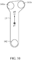
- FIG. 10 is a top view illustrating a relationship between a setting point and a COP according to at least one example embodiment.
- a COP p4 determined by the plurality of pressure sensors 141a, 141b, and 142 may be positioned at the front of the setting point p1.
- a magnitude of pressure measured by the first front pressure sensor 141a and/or the second front pressure sensor 141b may be greater than that of pressure measured by the rear pressure sensor 142.
- the controller 16 may control a magnitude of vibration of a vibrator provided in a rear portion to be greater than that of vibration of a vibrator provided in a front portion, thereby enhancing a sensitivity of a rearfoot of the user U.
- the controller 16 may drive only the vibrator provided in the rear portion and may not drive the vibrator provided in the front portion.
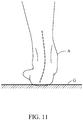
- FIG. 11 is a rear view illustrating an off-balance state of an ankle
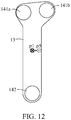
- FIG. 12 is a top view illustrating a relationship between a setting point and a COP in a state of FIG. 11 .
- a COP p5 determined by the plurality of pressure sensors 141a, 141b, and 142 may be positioned on the right of a setting point p1. For example, a magnitude of pressure measured by the second front pressure sensor 141b may be greater than that of pressure measured by the first front pressure sensor 141a.
- the controller 16 may control an intensity of vibration of a vibrator provided on the left to be greater than that of a vibrator provided on the left, thereby enhancing a sensitivity of a left side of the foot of the user.
- the controller 16 may drive only the vibrator provided on the left and may not drive the vibrator provided on the right.
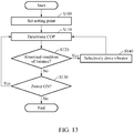
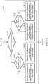
- FIG. 13 is a flowchart illustrating sequence in which a smart shoe maintains balance according to at least one example embodiment
- FIG. 14 is a flowchart illustrating an operation of determining whether balance is being maintained of FIG. 13
- FIG. 15 is a flowchart illustrating an operation of selectively driving a vibrator of FIG. 13 .
- the smart shoe may enhance balance of a user by selectively controlling a vibration to be applied from a plurality of vibrators.
- a method of enhancing, by the smart shoe, the balance of the user may include operation S100 of setting a setting point, operation S110 of determining a COP, operation S120 of determining whether the balance is being maintained, operation S130 of verifying whether a power is ON, and operation S140 of selectively driving a vibrator. Operations S100 to S140 may be performed by the controller 16.
- the controller 16 may receive an input of setting point data from the user.
- the user may input the setting point data in advance before performing a balance enhancement operation, or may continuously update a setting point through a wireless communication while performing the balance enhancement operation.
- the setting point may be set as an ideal COP point in a state in which the user is maintained in a correct posture.
- the controller 16 may determine the COP.
- the controller may determine the COP based on pressure information sensed by the plurality of pressure sensors 141, 142. For example, if a pressure value measured by one or more of the pressure sensors 141 provided at the front of the setting point is greater than a pressure value measured by the pressure sensor 142 provided at the rear of the setting point, the controller 16 may determine the COP to be positioned forward of the setting point.
- the controller 16 may determine whether the user is currently in an abnormal condition of balance.
- the controller 16 may determine whether the user is in the abnormal condition of balance based on a positional relationship between the setting point and the COP.
- the controller 16 may determine that the user is in an abnormal condition of front-and-rear balance and may control, among the plurality of vibrators, an intensity of vibration of a vibrator provided at the front of the setting point to differ from that of a vibrator provided at the rear of the setting point.
- the controller 16 may control, among the plurality of vibrators, intensity of vibration of the vibrator 152 provided at the rear of the setting point to be greater than that of the vibrators 151 provided in front of the setting point. In this manner, it is possible to relatively enhance a sensitivity of a rearfoot of the user and to make the COP move backward. Accordingly, the COP may approach the setting point.
- the controller 16 may control, among the plurality of vibrators, intensity of vibration of one or more of the vibrators 151 at the front of the setting point to be greater than that of the vibrator 152 provided at the rear. In this manner, it is possible to relatively enhance a sensitivity of a forefoot of the user and to make the COP move forward. Accordingly, the COP may approach the setting point.
- the controller 16 may determine that the user is in an abnormal condition of left-and-right balance and may control, among the plurality of vibrators, intensity of vibration of the vibrator 141a present on the left of the setting point to differ from that of the vibrator 141b present on the right of the setting point.
- the controller 16 may control, among the plurality of vibrators, intensity of vibration of the vibrator 141b present on the right of the setting point to be greater than that of the vibrator 141a present on the left of the setting point.
- intensity of vibration of the vibrator 141b present on the right of the setting point may be greater than that of the vibrator 141a present on the left of the setting point.
- the controller 16 may control, among the plurality of vibrators, intensity of vibration of the vibrator 141a present on the left of the setting point to be greater than that of the vibrator141b present on the right of the setting point. In this manner, it is possible to relatively enhance a sensitivity of a left-side portion of a foot of the user and to make the COP move to the left. Accordingly, the COP may approach the setting point.
- operation S120 in which the controller 16 determines whether the user is in an abnormal condition of balance may include operation S121 of measuring a distance d1 from a first auxiliary line to the COP, operation S122 of measuring a distance d2 from a second auxiliary line to the COP, operation S123 of determining whether d1 is greater than or equal to a first setting distance, and operation S124 of determining whether d2 is greater than or equal to a second setting distance.
- operation S121 of measuring a distance d1 from a first auxiliary line to the COP may include operation S121 of measuring a distance d1 from a first auxiliary line to the COP, operation S122 of measuring a distance d2 from a second auxiliary line to the COP, operation S123 of determining whether d1 is greater than or equal to a first setting distance, and operation S124 of determining whether d2 is greater than or equal to a second setting distance.
- the first auxiliary line refers to an auxiliary line that is perpendicular to a longitudinal direction of a support layer and passes the setting point
- the second auxiliary line refers to an auxiliary line that is parallel to the longitudinal direction of the support layer and passes the setting point.
- the controller 16 may determine that the user is in an abnormal condition of balance. For example, if d1 is greater than or equal to the first setting distance, the controller 16 may determine that the user is in an abnormal condition of front-and-rear balance. For example, if d2 is greater than or equal to the second setting distance, the controller 16 may determine that the user is in an abnormal condition of left-and-right balance.
- the first setting distance and/or the second setting distance are adjustable.
- the controller 16 may determine whether to iteratively re-perform the determination of the COP based on whether the power is ON. When the power is ON, the controller 16 may perform operation S110 of receiving pressure information from the plurality of pressure sensors and determining the COP. When the power is OFF, the controller 16 may stop a balance enhancement operation.
- the controller 16 may selectively drive one or more of the plurality of vibrators 151, 152.
- operation S140 may include operation S141 of determining whether d1 is greater than or equal to the first setting distance, operation S142 of determining whether the COP is positioned at the front of the setting point, operation S143 of controlling intensity of vibration of one or more front vibrators 151 to be greater than that of a rear vibrator 152, operation S144 of controlling intensity of vibration of the rear vibrator 152 to be greater than that of one or more of the front vibrators 151, operation S145 of determining whether the COP is positioned on the left of the setting point, operation S146 of controlling intensity of vibration of a first front vibrator to be greater than that of a second front vibrator, and operation S147 of controlling intensity of vibration of the second front vibrator 151b to be greater than that of the first front vibrator 151a.
- first front vibrator 151a and the second front vibrator 151b are spaced apart from each other in a direction that intersects the longitudinal direction of the support layer, and the first front vibrator 151a denotes a vibrator provided on the left of the second front vibrator 151b.
- FIG. 16 is a top view illustrating a base, a plurality of pressure sensors, and a plurality of vibrators according to at least one example embodiment.
- a plurality of pressure sensors 24 and a plurality of vibrator 25 may be distributed all over a support layer 23.
- a controller (not shown) may determine a COP based on a pressure distribution measured by the plurality of pressure sensors 24, may determine a positional relationship between the determined COP and a set (or, alternatively, a preset) setting point, and may individually control intensity of vibration of each of the plurality of vibrators 25 based on the determined positional relationship.
- the setting point may be updated in real time.
- the controller may control, among the plurality of vibrators 25, intensity of vibration of a vibrator provided at the rear of the setting point to be greater than that of a vibrator provided at the front of the setting point. In this manner, it is possible to enhance a sensitivity of a rearfoot of the user and to make the COP move backward.
- FIG. 17 illustrates a balance enhancement device according to at least one example embodiment.
- the balance enhancement device may include a left smart insole, a right smart insole, and a controller 2 configured to control the left smart insole and the right smart insole.
- the left smart insole may include a left support layer 33 configured to support a left foot of a user, left pressure sensors 341 and 342 provided to the left support layer 33, and a left vibrator 35 provided to the left support layer 33.
- the left pressure sensors 341 and 342 may sense a pressure applied from the left foot of the user.
- the left pressure sensors 341 and 342 may include the left front pressure sensor 341 configured to overlap a forefoot of the left foot of the user and the left rear pressure sensor 342 configured to overlap a rearfoot of the left foot of the user.
- the right smart insole may include a right support layer 43 configured to support a right foot of the user, right pressure sensors 441 and 442 provided to the right support layer 43, and a right vibrator 45 provided to the right support layer 43.
- the right pressure sensors 441 and 442 may sense a pressure applied from the right foot of the user.
- the right pressure sensors 441 and 442 may include the right front pressure sensor 441 configured to overlap a forefoot of the right foot of the user and the right rear pressure sensor 442 configured to overlap a rearfoot of the right foot of the user.
- the controller 2 may include processing circuitry including, but is not limited to, a central processing unit (CPU), an arithmetic logic unit (ALU), a digital signal processor, a microcomputer, a field programmable gate array (FPGA), a programmable logic unit, a microprocessor, application-specific integrated circuit (ASIC), etc.
- the processing circuitry of controller 2 may execute instructions that configure the processing circuitry as special purpose processing circuitry to compare the pressure measured by the left pressure sensors 341 and 342 and the pressure measured by the right pressure sensors 441 and 442, and may adjust intensity of vibration of the left vibrator 35 and the right vibrator 45.
- the controller 2 may control the left vibrator 35 and the right vibrator 45 such that the intensity of vibration of the right vibrator 45 may be greater than that of the left vibrator 35.
- the sensitivity of the right foot of the user may be relatively enhanced and a center of gravity of the user may move to the right foot.
- a magnitude of pressure measured by the left pressure sensors 341 and 342 may decrease and a magnitude of pressure measured by the right pressure sensors 441 and 442 may increase.
- a difference between the pressure measured by the left pressure sensors 341 and 342 and the pressure measured by the right pressure sensors 441 and 442 may decrease.
- FIG. 17 illustrates a single left vibrator 35 and a single right vibrator 45
- example embodiments are not limited thereto.
- each of the left vibrator 35 and the right vibrator may include the two front vibrators 151 and the rear vibrator 152.
- the left smart insole and the right smart insole may each include their own respective controller 16 configured to communicate with the common controller 2.
Landscapes
- Health & Medical Sciences (AREA)
- Life Sciences & Earth Sciences (AREA)
- Engineering & Computer Science (AREA)
- Public Health (AREA)
- General Health & Medical Sciences (AREA)
- Physics & Mathematics (AREA)
- Surgery (AREA)
- Dentistry (AREA)
- Biomedical Technology (AREA)
- Heart & Thoracic Surgery (AREA)
- Medical Informatics (AREA)
- Molecular Biology (AREA)
- Biophysics (AREA)
- Animal Behavior & Ethology (AREA)
- Oral & Maxillofacial Surgery (AREA)
- Pathology (AREA)
- Veterinary Medicine (AREA)
- Microelectronics & Electronic Packaging (AREA)
- Epidemiology (AREA)
- General Physics & Mathematics (AREA)
- Physiology (AREA)
- Business, Economics & Management (AREA)
- Emergency Management (AREA)
- Footwear And Its Accessory, Manufacturing Method And Apparatuses (AREA)
Abstract
Description
- Some example embodiments relate to a smart insole and/or a balance enhancement device including the smart insole.
- A user wears shoes in daily life to protect feet of the user comfortably and safely. In recent years, wearable devices are developed to detect a gait pattern of the user and to assist the user to stably walk by providing a sensor and/or an actuator to a shoe.
- Some example embodiments relate to a smart insole configured to be worn by a user.
- In some example embodiments, the smart insole may include a support layer; a plurality of pressure sensors associated with the support layer, the plurality of pressure sensors configured to sense a pressure applied thereto by a foot of the user; a plurality of vibrators associated with the support layer, the plurality of vibrators configured to generate a vibration; and a controller configured to, determine a center of pressure (COP) of the foot of the user based on the pressure sensed by each of the plurality of pressure sensors, and control the plurality of vibrators based on a positional relationship between a setting point and the COP.
- In some example embodiments, the plurality of vibrators is configured to generate the vibration such that an intensity of the vibration is less than a threshold of a sole of the foot of the user.
- In some example embodiments, the controller is configured to control the plurality of vibrators based on information on at least one of a distance from the COP to the setting point and a direction from the COP toward the setting point.
- In some example embodiments, the controller is configured to control the plurality of vibrators such that, among the plurality of vibrators, an intensity of the vibration rearward of the setting point is greater than that of an intensity of the vibration provided forward of the setting point, in response to the controller determining that the COP is in front of the setting point.
- In some example embodiments, the controller is configured to control the plurality of vibrators such that ones of the plurality of vibrators rearward of the setting point vibrate and ones of the plurality of vibrators forward of the setting point do not vibrate, in response to the controller determining that the COP is in front of the setting point.
- In some example embodiments, the controller is configured to, determine whether a distance from a first auxiliary line to the COP is greater than or equal to a first threshold distance, the first auxiliary line being perpendicular to a longitudinal direction of the support layer and intersecting the setting point, and determine that the COP is positioned at the front of the setting point, if the distance from the first auxiliary line to the COP is greater than or equal to the first threshold distance and the COP is positioned at the front of the setting point.
- In some example embodiments, the controller is configured to control the plurality of vibrators such that, among the plurality of vibrators, an intensity of the vibration on a right side of the setting point is greater than an intensity of the vibration on a left side of the setting point, in response to the controller determining that the COP is on the left side of the setting point.
- In some example embodiments, the controller is configured to control the plurality of vibrators such that ones of the plurality of vibrators on the right side of the setting point vibrate and ones of the plurality of vibrators on the left side of the setting point do not vibrate, in response to the controller determining that the COP is on the left side of the setting point.
- In some example embodiments, the controller is configured to, determine whether a distance from a second auxiliary line is greater than or equal to a second setting threshold, the second auxiliary line being parallel to a longitudinal direction of the support layer and intersecting the setting point to the COP, and determine that the COP is positioned on the left side of the setting point, if the distance from the second auxiliary line is greater than or equal to the second setting threshold and the COP is positioned at the left of the setting point.
- In some example embodiments, the plurality of vibrators include a front vibrator configured to apply a vibration to a forefoot of the user; and a rear vibrator configured to apply a vibration to a rearfoot of the user.
- In some example embodiments, the controller is configured to vibrate one or more of the front vibrator and the rear vibrator based on the positional relationship between the setting point and the COP.
- In some example embodiments, the front vibrator includes a right front vibrator and a left front vibrator that are aligned in a width direction of the support layer, and wherein the controller is configured to control plurality of vibrators such that the right front vibrator vibrates and the left front vibrator does not vibrate, in response to the controller determining that the COP is positioned on a left side of the setting point.
- In some example embodiments, the smart insole further includes a base configured to support the support layer; and a cover detachably provided to the base, wherein the support layer is provided between the base and the cover.
- Some example embodiments relate to a smart insole configured to be worn by a user.
- In some example embodiments, the smart insole includes a support layer; a plurality of pressure sensors associated with the support layer, the plurality of pressure sensors configured to sense a pressure applied thereto by a foot of the user; a plurality of vibrators associated with the support layer, the plurality of vibrators configured to generate a vibration having an intensity less than a threshold of a sole of the foot of the user; and a controller configured to, determine a center of pressure (COP) of the foot of the user based on the pressure sensed by each of the plurality of pressure sensors, determine whether the user is in an abnormal condition of balance based on a positional relationship between a setting point and the COP, and control the plurality of vibrators such that the intensity of the vibration is different in at least a portion of the plurality of vibrators.
- In some example embodiments, the controller is configured to, determine that the user is in the abnormal condition of balance in response to the controller determining that the COP is in front of or behind the setting point, and control the plurality of vibrators such that, among the plurality of vibrators, the intensity of the vibration forward of the setting point differs from the intensity of the vibration rearward of the setting point, in response to the controller determining that the COP is in front of or behind the setting point.
- In some example embodiments, the controller is configured to, determine that the user is in the abnormal condition of balance in response to the controller determining that the COP is on a left side or on a right side of the setting point, and control the plurality of vibrators such that, among the plurality of vibrators, the intensity of the vibration on the left side of the setting point differs from the intensity of the vibration on the right side of the setting point in response to the controller determining that the COP is on the left side or on the right side of the setting point.
- Some example embodiments relate to a balance enhancement device.
- In some example embodiments, the balance enhancement device may include a left smart insole including a left support layer configured to support a left foot of a user, the left support layer having at least one left pressure sensor and at least one left vibrator associated therewith; a right smart insole including a right support layer configured to support a right foot of the user, the right support layer having at least one right pressure sensor and at least one right vibrator associated therewith; and a controller configured to control the at least one left vibrator and the at least one right vibrator such that an intensity of a vibration generated thereby differs based on a pressure value measured by the left pressure sensor and the right pressure sensor.
- In some example embodiments, the controller is configured to control the at least one left vibrator and the at least one right vibrator such that the intensity of the vibration of the at least one right vibrator is greater the intensity of the vibration of the at least one left vibrator, in response to the controller determining that the pressure value measured by the at least one left pressure sensor is greater than the pressure value measured by the at least one right pressure sensor.
- In some example embodiments, the controller is configured to control the at least one left vibrator and the at least one right vibrator such that the at least one right vibrator vibrates and the left at least one vibrator does not vibrate, in response to the controller determining that the pressure value measured by the left pressure sensor is greater than the pressure value measured by the right pressure sensor.
- In some example embodiments, the at least one left vibrator and the at least one right vibrator are configured to generate the vibration such that the intensity of the vibration is less than a threshold of a sole of the user.
- Additional aspects of example embodiments will be set forth in part in the description which follows and, in part, will be apparent from the description, or may be learned by practice of the disclosure.
- These and/or other aspects will become apparent and more readily appreciated from the following description of example embodiments, taken in conjunction with the accompanying drawings of which:
-
FIG. 1 is a side view of a smart shoe according to at least one example embodiment; -
FIG. 2 is a top view illustrating a smart insole according to at least one example embodiment; -
FIG. 3 is a cross-sectional view illustrating the smart insole cut along line III-III ofFIG. 2 ; -
FIG. 4 is a top view illustrating a smart insole from which a cover is separated according to at least one example embodiment; -
FIG. 5 is a top view illustrating a support layer, a plurality of pressure sensors, and a plurality of vibrators according to at least one example embodiment; -
FIG. 6 is a block diagram illustrating a configuration of a smart shoe according to at least one example embodiment; -
FIG. 7 is a side view illustrating a user of which a posture is biased backward according to at least one example embodiment; -
FIG. 8 is a top view illustrating a relationship between a setting point and a center of pressure (COP) in a state ofFIG. 7 ; -
FIG. 9 is a side view illustrating a user of which a posture is biased forward according to at least one example embodiment; -
FIG. 10 is a top view illustrating a relationship between a setting point and a COP in a state ofFIG. 9 ; -
FIG. 11 is a rear view illustrating an off-balance state of an ankle; -
FIG. 12 is a top view illustrating a relationship between a setting point and a COP in a state ofFIG. 11 ; -
FIG. 13 is a flowchart illustrating sequence in which a smart shoe maintains balance according to at least one example embodiment; -
FIG. 14 is a flowchart illustrating an operation of determining whether balance is being maintained ofFIG. 13 ; -
FIG. 15 is a flowchart illustrating an operation of selectively driving a vibrator ofFIG. 13 ; -
FIG. 16 is a top view illustrating a base, a plurality of pressure sensors, and a plurality of vibrators according to at least one example embodiment; and -
FIG. 17 illustrates a balance enhancement device according to at least one example embodiment. - Hereinafter, some example embodiments will be described in detail with reference to the accompanying drawings. Regarding the reference numerals assigned to the elements in the drawings, it should be noted that the same elements will be designated by the same reference numerals, wherever possible, even though they are shown in different drawings. Also, in the description of example embodiments, detailed description of well-known related structures or functions will be omitted when it is deemed that such description will cause ambiguous interpretation of the present disclosure.
- In addition, terms such as first, second, A, B, (a), (b), and the like may be used herein to describe components. Each of these terminologies is not used to define an essence, order or sequence of a corresponding component but used merely to distinguish the corresponding component from other component(s). It should be noted that if it is described in the specification that one component is "connected", "coupled", or "joined" to another component, a third component may be "connected", "coupled", and "joined" between the first and second components, although the first component may be directly connected, coupled or joined to the second component.
- A component including a common function with a component in one example embodiment is described using the same term in another example embodiment. Unless the context clearly indicates otherwise, description made in one example embodiment may apply to another example embodiment and repetitive description is omitted.
-
FIG. 1 is a side view of a smart shoe according to at least one example embodiment,FIG. 2 is a top view illustrating a smart insole according to at least one example embodiment,FIG. 3 is a cross-sectional view illustrating the smart insole cut along line III-III ofFIG. 2 , andFIG. 4 is a top view illustrating a smart insole from which a cover is separated according to at least one example embodiment. - Referring to
FIGS. 1 to 4 , asmart shoe 100 may include asmart insole 1, amidsole 91, and an upper 92. Thesmart shoe 100 may sense pressure applied from a foot of a user using a plurality ofpressure sensors smart insole 1, and may verify a center of pressure (COP) of a sole of the user. Thesmart shoe 100 may apply a vibration to the sole of the user using a plurality ofvibrators smart insole 1. The plurality ofvibrators - In the following direction, a longitudinal direction of the
smart shoe 100 denotes a y-axial direction, a widthwise direction of thesmart shoe 100 denotes an x-axial direction, and a height direction of thesmart shoe 100 denotes a z-axial direction. Hereinafter, the term "front" denotes +y direction and the term "rear" denotes -y direction in a coordinate system ofFIG. 1 , unless the context clearly indicates otherwise. - The
smart insole 1 may sense the pressure applied from the sole of the user and may apply an appropriate stimulus to the sole of the user, thereby enhancing balance of the user. For example, if the COP of the sole of the user is too far forward, thesmart insole 1 may enhance a sensitivity of the rearfoot of the user by applying a vibration to a rear portion of the sole of the user, that is, the rearfoot of the user to cause the COP of the sole of the user move backward. For example, a stimulus applied by thesmart insole 1 to the user may be less than or equal to a threshold. - The
smart insole 1 may include a surface in contact with the sole of the user and may support the foot of the user. Thesmart insole 1, aside from an electronic device, for example, thepressure sensors vibrators smart insole 1 may insert inward into the upper 92 or may separate from the upper 92 through an opening provided in an upper portion of the upper 92. Thesmart insole 1 may be provided on a floor of the upper 92. If the upper 92 does not include the floor, thesmart insole 1 may be provided on a top surface of themidsole 91. - Here, although the
smart insole 1 is described as one component of thesmart shoe 100, it is provided as an example only. For example, thesmart insole 1 may insert into a sock and may perform a pressure measurement and a vibration application, thereby enhancing the balance of the user. As another example, thesmart insole 1 may apply to various wearable devices, for example, a motion assist robot. - The
smart insole 1 may include abase 11, acover 12, asupport layer 13, the plurality ofpressure sensors vibrators controller 16, aninsert 17, and aconnection line 19. Thebase 11 and thecover 12 may be combined with each other or may be separated from each other. The user may separate thecover 12 and may clean and/or replace thecover 12. Electronic elements provided in thesmart insole 1, for example, the plurality ofpressure sensors vibrators controller 16 may be provided to thebase 11. Thecover 12 may not include any of the electronic elements. Thecover 12 makes a direct contact with the sole of the user. Therefore, thecover 12 may be relatively easily contaminated compared to the base 11 that makes an indirect contact with the sole of the user. The user may separate and clean only thecover 12. In this manner, thesmart shoe 100 may be maintained to be in a hygienically excellent state. - The base 11 may have a shape corresponding to an internal space of the upper 92. For example, the
base 11 may insert inward into the upper 92 through the opening provided in the upper portion of the upper 92. The base 11 may include abase protrusion 11a configured to enhance a combining force with thecover 12 and a base hole 11b configured to guide theconnection line 19 to thecontroller 16. - The
base protrusion 11a may protrude upward, may insert into thecover 12, and may support thecover 12 such that thecover 12 does not move relative to thebase 11. For example, thebase protrusion 11a may be fitted to thecover 12. Here, the expression "fit" may inclusively indicate tight fit and any mutual coupling methods capable of reducing a phenomenon that thecover 12 slides relative to thebase 11. Thecover 12 may include a groove (not shown) recessed from a bottom surface of thecover 12, and thebase protrusion 11a may insert into the groove. Thebase protrusion 11a may prevent thecover 12 from sliding in a horizontal direction, for example, the x-axial direction or the y-axial direction. Thebase protrusion 11a may surround thesupport layer 13 and may fasten thesupport layer 13. Although thebase protrusion 11a is illustrated in a shape of a closed curve, it is provided as an example only. For example, thebase protrusion 11a may be in a shape including a plurality of unit bodies. - The base hole 11b may be formed to vertically penetrate the
base 11. The base hole 11b may be formed in a direction perpendicular to thesmart insole 1, that is, the z-axial direction. The base hole 11b may function as a path that guides theconnection line 19 from the top surface to the bottom surface of thebase 11. Theconnection line 19 that passes through the base hole 11b may be connected to thecontroller 16. According to the above structure, the plurality ofpressure sensors vibrators controller 16 may decrease, thereby enhancing the durability of thecontroller 16. - The base hole 11b may be formed in a space in which the plurality of
pressure sensors vibrators connection line 19 passing the base hole 11b may relatively decrease and a disconnection risk of theconnection line 19 may also decrease accordingly. For example, during a push-off phase, a relatively strong pressure may apply to a portion that overlaps a forefoot, that is, thepressure sensor 141 and thevibrator 151 provided in a front portion of thesmart insole 1. Likewise, during a heel-strike phase, a relatively strong pressure may apply to a portion that overlaps a rearfoot, that is, thepressure sensor 142 and thevibrator 152 provided in a rear portion of thesmart insole 1. Meanwhile, during the overall gait phase, a relatively small pressure may apply to a portion that overlaps a middle portion of thesmart insole 1, that is, around the base hole 11b. - The
cover 12 is detachably provided to thebase 11. Thecover 12 may cover the plurality ofpressure sensors vibrators pressure sensors vibrators cover 12 may be approximately similar to a shape of thebase 11. Thecover 12 may mostly overlap the base 11 based on a vertical direction of thesmart insole 1. For example, an electronic part may not be provided in thecover 12. According to the above structure, the user may separate and thereby clean or replace thecover 12 alone. Also, without modifying a structure of the base 11 including various types of electronic elements, thecover 12 in a shape customized for a shape of the foot of the user may be provided. Accordingly, cost and effort used to manufacture thesmart shoe 100 may be saved. - The
support layer 13 may support the plurality ofpressure sensors vibrators base protrusion 11a. Thesupport layer 13 may be fitted to thebase protrusion 11a. Thesupport layer 13 may be tightly fastened inside thebase protrusion 11a. Thesupport layer 13 may be formed of a flexible film. - The plurality of
pressure sensors pressure sensors - The plurality of
pressure sensors front pressure sensor 141 and arear pressure sensor 142. Thefront pressure sensor 141 may overlap the forefoot of the user. Therear pressure sensor 142 may overlap the rearfoot of the user. Thefront pressure sensor 141 may include a firstfront pressure sensor 141a provided on the left and a secondfront pressure sensor 141b provided on the right. - The plurality of
vibrators vibrators vibrators vibrators - The plurality of
vibrators front vibrator 151 and arear vibrator 152. Thefront vibrator 151 may overlap the forefoot of the user. Therear vibrator 152 may overlap the rearfoot of the user. Thefront vibrator 151 may include a firstfront vibrator 151a provided on the left and a secondfront vibrator 151b provided on the right. - The
controller 16 may include processing circuitry including, but is not limited to, a central processing unit (CPU), an arithmetic logic unit (ALU), a digital signal processor, a microcomputer, a field programmable gate array (FPGA), a programmable logic unit, a microprocessor, application-specific integrated circuit (ASIC), etc. The processing circuitry may execute instructions that configure the processing circuitry as special purpose processing circuitry that determines the COP sensed by the plurality ofpressure sensors vibrators smart shoe 1 itself by applying an appropriate stimulus to the sole of the user, thereby enhancing balance of the user. - The
controller 16 may physically and/or electrically connect to the plurality ofpressure sensors vibrators controller 16 may set (or, alternatively, preset) the setting point. Here, the setting point may be an ideal COP. Thecontroller 16 may set, as the setting point, the ideal COP, that is, the COP when the use is standing or walking in a correct posture. The ideal COP may be determined through an empirical study. For example, an empirical study may be performed where users walk on a capacitive pressure platform at their normal pace and the pressure distribution of the users is analyzed to determine the ideal COP, where the ideal COP for different users may be broken up based on age, sex, weight and other factors. Thecontroller 16 may determine the COP, that is, the actual COP based on the pressure sensed by the plurality ofpressure sensors - The
controller 16 may control the plurality ofvibrators controller 16 may control the plurality ofvibrators - When the COP is positioned forward of the setting point, the
controller 16 may selectively drive a vibrator provided at the rear and may not drive a vibrator provided at the front. In this case, sensitivity of a rearfoot portion of the user increases and a center of gravity of the user moves backward. Accordingly, the COP approaches the setting point. In this manner, thecontroller 16 may perform a control for enhancing balance of the user. - Likewise, when the COP is positioned rearward of the setting point, the
controller 16 may selectively drive a vibrator provided at the front and may not drive a vibrator provided at the rear. In this case, sensitivity of a forefoot portion of the user increases and a center of gravity of the user moves forward. Accordingly, the COP approaches the setting point. - In some example embodiments, the
controller 16 may control the selected vibrator to generate the desired intensity of vibration where the vibration has a frequency that changes (e.g. randomly) such that at least a portion of the vibration resonates along with an external stimulus. - In some example embodiments, the
controller 16 may estimate a posture of the user by measuring foot pressure of the user, and selectively activate the selected vibrator only when the posture of the user is a walking posture and/or a standing posture. Therefore, thecontroller 16 may improve the functioning of thesmart shoe 1 itself by reducing power consumption of the battery and/or increasing comfortableness that may be experienced by the user. - In some example embodiments, the
controller 16 may be in communication with a walking assistance apparatus worn by the user, and instruct the walking assistance apparatus to output an assistance force that re-balances pressures applied to the sole of the user based on the detected COP.
Walkingassistance apparatus 100 may output an assistance force that re-balances pressures applied to the left portion and the right portion of the sole of the user. - The
controller 16 may be provided to thesmart insole 1. However, it is provided as an example only. For example, thecontroller 16 may be provided to themidsole 91. - The
insert 17 may be provided in thebase 11 and may be formed of a more robust material than that of thebase 11. For example, theinsert 17 may be integrally formed inside thebase 11 by forming the base 11 through a resin foaming process and the like in a state in which thebase 11 is provided in advance in a frame. Theinsert 17 may overlap thecontroller 16 based on a direction perpendicular to thesmart insole 1. Although theinsert 17 is illustrated to fasten a front end of thecontroller 16, it is provided as an example only. A plurality ofinserts 17 may be provided to fasten another portion of thecontroller 16. Also, theinsert 17 may be in a different shape to fasten a plurality of portions of thecontroller 16. - The
connection line 19 may electrically connect the plurality ofpressure sensors vibrators controller 16. Theconnection line 19 may extend from the plurality ofpressure sensors vibrators base 11. Theconnection line 19 may extend from the top surface of the base 11 to the bottom surface of the base 11 by penetrating the base hole 11b. An end of theconnection line 19 may connect to thecontroller 16 provided in a lower portion of thebase 11. One end of theconnection line 19 may be connected to the plurality ofpressure sensors vibrators connection line 19 may be connected to thecontroller 16. The plurality ofpressure sensors vibrators controller 16 through theconnection line 19. For example, theconnection line 19 may be provided on a top surface or a bottom surface of thesupport layer 13, or may be embedded in thesupport layer 13. Meanwhile, theconnection line 19 may be directly provided to abase 11 without using thesupport layer 13. -
FIG. 5 is a top view illustrating a support layer, a plurality of pressure sensors, and a plurality of vibrators according to at least one example embodiment, andFIG. 6 is a block diagram illustrating a configuration of a smart shoe according to at least one example embodiment. For clarity of description, a connection line is omitted inFIG. 5 . - Referring to
FIGS. 5 and6 , thecontroller 16 may receive pressure information from the firstfront pressure sensor 141a, the secondfront pressure sensor 141b, and therear pressure sensor 142, and may determine a COP p2. The firstfront pressure sensor 141a may be spaced apart to the left from the secondfront pressure sensor 141b. - The
controller 16 may compare the COP p2 to a setting point p1. For example, the setting point p1 may be an ideal COP point when the user is in a correct posture. The setting point p1 may be set (or, alternatively, preset) and a position of the setting point p1 may vary in real time during use. When the posture of the user leans forward, the COP p2 may be positioned forward of the setting point p1. Likewise, when the posture of the user leans backward, the COP p2 may be positioned rearward of the setting point p1. - For example, referring to
FIG. 5 , the COP p2 may be positioned at the front and on the right relative to the setting point p1. A distance from a first auxiliary line L1 that is perpendicular to a longitudinal direction (y-axial direction) of thesupport layer 13 and passes the setting point p1 to the COP p2 may be d1. A distance from a second auxiliary line L2 that is parallel to the longitudinal direction (y-axial direction) of thesupport layer 13 and passes the setting point p1 to the COP p2 may be d2. - The
controller 16 may compare d1 to a first setting distance to generate a comparison result, and may determine whether the COP p2 is positioned at the front of the setting point p1 based on the comparison result. The user may adjust the first setting distance. For example, if the user desires to maintain a relatively high level of balance, the user may set the first setting distance to be relatively small. - If d1 is maintained to be greater than or equal to the first setting distance during a first setting time or more, the
controller 16 may determine that the user is in an abnormal condition of balance. The user may adjust the first setting time. For example, if the user desires to maintain a relatively high level of balance, the user may set the first setting time to be relatively short. - Hereinafter, a positional relationship between the setting point p1 and the COP according to an abnormal condition of balance of the user is described with reference to
FIGS. 7 to 12 . -
FIG. 7 is a side view illustrating a user of which a posture is biased backward, that is, leans backward according to at least one example embodiment, andFIG. 8 is a top view illustrating a relationship between a setting point and a COP in a state ofFIG. 7 . - Referring to
FIGS. 7 and8 , when a posture of a user U leans backward based on a ground G, for example, when an upper body of the user U leans backward, a COP p3 determined by the plurality ofpressure sensors rear pressure sensor 142 may be greater than that of pressure measured by the firstfront pressure sensor 141a and/or secondfront pressure sensor 141b. - In this case, the controller 16 (
FIG. 6 ) may control an intensity of vibration of a vibrator provided in a front portion to be greater than that of a vibrator provided in a rear portion, thereby enhancing a sensitivity of a forefoot of the user U. For example, thecontroller 16 may drive only the vibrator provided in the front portion and may not drive the vibrator provided in the rear portion. -
FIG. 9 is a side view illustrating a user of which a posture is biased forward, that is, leans forward according to at least one example embodiment, andFIG. 10 is a top view illustrating a relationship between a setting point and a COP according to at least one example embodiment. - Referring to
FIGS. 9 and10 , when a posture of a user U leans forward based on a ground G, for example, when an upper portion of the user U leans forward, a COP p4 determined by the plurality ofpressure sensors front pressure sensor 141a and/or the secondfront pressure sensor 141b may be greater than that of pressure measured by therear pressure sensor 142. - In this case, the
controller 16 may control a magnitude of vibration of a vibrator provided in a rear portion to be greater than that of vibration of a vibrator provided in a front portion, thereby enhancing a sensitivity of a rearfoot of the user U. For example, thecontroller 16 may drive only the vibrator provided in the rear portion and may not drive the vibrator provided in the front portion. -
FIG. 11 is a rear view illustrating an off-balance state of an ankle, andFIG. 12 is a top view illustrating a relationship between a setting point and a COP in a state ofFIG. 11 . - Referring to
FIGS. 11 and12 , when an ankle A of a user bends inward, a relatively large weight of a user may be loaded to inside of a foot. A COP p5 determined by the plurality ofpressure sensors front pressure sensor 141b may be greater than that of pressure measured by the firstfront pressure sensor 141a. - In this case, the
controller 16 may control an intensity of vibration of a vibrator provided on the left to be greater than that of a vibrator provided on the left, thereby enhancing a sensitivity of a left side of the foot of the user. For example, thecontroller 16 may drive only the vibrator provided on the left and may not drive the vibrator provided on the right. -
FIG. 13 is a flowchart illustrating sequence in which a smart shoe maintains balance according to at least one example embodiment,FIG. 14 is a flowchart illustrating an operation of determining whether balance is being maintained ofFIG. 13 , andFIG. 15 is a flowchart illustrating an operation of selectively driving a vibrator ofFIG. 13 . - Referring to
FIGS. 13 to 15 , the smart shoe may enhance balance of a user by selectively controlling a vibration to be applied from a plurality of vibrators. A method of enhancing, by the smart shoe, the balance of the user may include operation S100 of setting a setting point, operation S110 of determining a COP, operation S120 of determining whether the balance is being maintained, operation S130 of verifying whether a power is ON, and operation S140 of selectively driving a vibrator. Operations S100 to S140 may be performed by thecontroller 16. - In operation S100, the
controller 16 may receive an input of setting point data from the user. For example, the user may input the setting point data in advance before performing a balance enhancement operation, or may continuously update a setting point through a wireless communication while performing the balance enhancement operation. The setting point may be set as an ideal COP point in a state in which the user is maintained in a correct posture. - In operation S110, the
controller 16 may determine the COP. The controller may determine the COP based on pressure information sensed by the plurality ofpressure sensors pressure sensors 141 provided at the front of the setting point is greater than a pressure value measured by thepressure sensor 142 provided at the rear of the setting point, thecontroller 16 may determine the COP to be positioned forward of the setting point. - In operation S120, the
controller 16 may determine whether the user is currently in an abnormal condition of balance. Thecontroller 16 may determine whether the user is in the abnormal condition of balance based on a positional relationship between the setting point and the COP. When the COP is positioned forward or rear of the setting point, thecontroller 16 may determine that the user is in an abnormal condition of front-and-rear balance and may control, among the plurality of vibrators, an intensity of vibration of a vibrator provided at the front of the setting point to differ from that of a vibrator provided at the rear of the setting point. - For example, when the COP is positioned forward of the setting point, the
controller 16 may control, among the plurality of vibrators, intensity of vibration of thevibrator 152 provided at the rear of the setting point to be greater than that of thevibrators 151 provided in front of the setting point. In this manner, it is possible to relatively enhance a sensitivity of a rearfoot of the user and to make the COP move backward. Accordingly, the COP may approach the setting point. - For example, when the COP is positioned rearward of the setting point, the
controller 16 may control, among the plurality of vibrators, intensity of vibration of one or more of thevibrators 151 at the front of the setting point to be greater than that of thevibrator 152 provided at the rear. In this manner, it is possible to relatively enhance a sensitivity of a forefoot of the user and to make the COP move forward. Accordingly, the COP may approach the setting point. - When the COP is positioned on the left or on the right of the setting point, the
controller 16 may determine that the user is in an abnormal condition of left-and-right balance and may control, among the plurality of vibrators, intensity of vibration of thevibrator 141a present on the left of the setting point to differ from that of thevibrator 141b present on the right of the setting point. - For example, when the COP is positioned on the left of the setting point, the
controller 16 may control, among the plurality of vibrators, intensity of vibration of thevibrator 141b present on the right of the setting point to be greater than that of thevibrator 141a present on the left of the setting point. In this manner, it is possible to relatively enhance a sensitivity of a right-side portion of a foot of the user and to make the COP move to the right. Accordingly, the COP may approach the setting point. - For example, when the COP is positioned on the right of the setting point, the
controller 16 may control, among the plurality of vibrators, intensity of vibration of thevibrator 141a present on the left of the setting point to be greater than that of the vibrator141b present on the right of the setting point. In this manner, it is possible to relatively enhance a sensitivity of a left-side portion of a foot of the user and to make the COP move to the left. Accordingly, the COP may approach the setting point. - Referring to
FIGS. 13 and14 , operation S120 in which thecontroller 16 determines whether the user is in an abnormal condition of balance may include operation S121 of measuring a distance d1 from a first auxiliary line to the COP, operation S122 of measuring a distance d2 from a second auxiliary line to the COP, operation S123 of determining whether d1 is greater than or equal to a first setting distance, and operation S124 of determining whether d2 is greater than or equal to a second setting distance. Here, referring toFIG. 5 , the first auxiliary line refers to an auxiliary line that is perpendicular to a longitudinal direction of a support layer and passes the setting point, and the second auxiliary line refers to an auxiliary line that is parallel to the longitudinal direction of the support layer and passes the setting point. - If the
controller 16 determines, in operation S123, that d1 is greater than or equal to the first setting distance and/or determines, in operation S124 that d2 is greater than or equal to the second setting distance, thecontroller 16 may determine that the user is in an abnormal condition of balance. For example, if d1 is greater than or equal to the first setting distance, thecontroller 16 may determine that the user is in an abnormal condition of front-and-rear balance. For example, if d2 is greater than or equal to the second setting distance, thecontroller 16 may determine that the user is in an abnormal condition of left-and-right balance. The first setting distance and/or the second setting distance are adjustable. When thecontroller 16 determines that the user is in the abnormal condition of balance, thecontroller 16 may selectively drive one or more of the plurality ofvibrators - If the
controller 16 determines that the user is not in the abnormal condition of balance (e.g., is normally balanced), in operation S130, thecontroller 16 may determine whether to iteratively re-perform the determination of the COP based on whether the power is ON. When the power is ON, thecontroller 16 may perform operation S110 of receiving pressure information from the plurality of pressure sensors and determining the COP. When the power is OFF, thecontroller 16 may stop a balance enhancement operation. - In contrast, if the
controller 16 determines that the user is in the abnormal condition of balance, in operation S140, thecontroller 16 may selectively drive one or more of the plurality ofvibrators - Referring to
FIGS. 13 and15 , operation S140 may include operation S141 of determining whether d1 is greater than or equal to the first setting distance, operation S142 of determining whether the COP is positioned at the front of the setting point, operation S143 of controlling intensity of vibration of one or morefront vibrators 151 to be greater than that of arear vibrator 152, operation S144 of controlling intensity of vibration of therear vibrator 152 to be greater than that of one or more of thefront vibrators 151, operation S145 of determining whether the COP is positioned on the left of the setting point, operation S146 of controlling intensity of vibration of a first front vibrator to be greater than that of a second front vibrator, and operation S147 of controlling intensity of vibration of the secondfront vibrator 151b to be greater than that of the firstfront vibrator 151a. Here, the firstfront vibrator 151a and the secondfront vibrator 151b are spaced apart from each other in a direction that intersects the longitudinal direction of the support layer, and the firstfront vibrator 151a denotes a vibrator provided on the left of the secondfront vibrator 151b. -
FIG. 16 is a top view illustrating a base, a plurality of pressure sensors, and a plurality of vibrators according to at least one example embodiment. - Referring to
FIG. 16 , a plurality ofpressure sensors 24 and a plurality ofvibrator 25 may be distributed all over asupport layer 23. A controller (not shown) may determine a COP based on a pressure distribution measured by the plurality ofpressure sensors 24, may determine a positional relationship between the determined COP and a set (or, alternatively, a preset) setting point, and may individually control intensity of vibration of each of the plurality ofvibrators 25 based on the determined positional relationship. The setting point may be updated in real time. - For example, when the COP is positioned forward of the setting point, the controller may control, among the plurality of
vibrators 25, intensity of vibration of a vibrator provided at the rear of the setting point to be greater than that of a vibrator provided at the front of the setting point. In this manner, it is possible to enhance a sensitivity of a rearfoot of the user and to make the COP move backward. -
FIG. 17 illustrates a balance enhancement device according to at least one example embodiment. - Referring to
FIG. 17 , the balance enhancement device may include a left smart insole, a right smart insole, and acontroller 2 configured to control the left smart insole and the right smart insole. - The left smart insole may include a
left support layer 33 configured to support a left foot of a user, leftpressure sensors left support layer 33, and aleft vibrator 35 provided to theleft support layer 33. Theleft pressure sensors left pressure sensors front pressure sensor 341 configured to overlap a forefoot of the left foot of the user and the leftrear pressure sensor 342 configured to overlap a rearfoot of the left foot of the user. - The right smart insole may include a
right support layer 43 configured to support a right foot of the user,right pressure sensors right support layer 43, and aright vibrator 45 provided to theright support layer 43. Theright pressure sensors right pressure sensors front pressure sensor 441 configured to overlap a forefoot of the right foot of the user and the rightrear pressure sensor 442 configured to overlap a rearfoot of the right foot of the user. - The
controller 2 may include processing circuitry including, but is not limited to, a central processing unit (CPU), an arithmetic logic unit (ALU), a digital signal processor, a microcomputer, a field programmable gate array (FPGA), a programmable logic unit, a microprocessor, application-specific integrated circuit (ASIC), etc. The processing circuitry ofcontroller 2 may execute instructions that configure the processing circuitry as special purpose processing circuitry to compare the pressure measured by theleft pressure sensors right pressure sensors left vibrator 35 and theright vibrator 45. For example, if a pressure value measured by theleft pressure sensors right pressure sensors controller 2 may control theleft vibrator 35 and theright vibrator 45 such that the intensity of vibration of theright vibrator 45 may be greater than that of theleft vibrator 35. In this case, the sensitivity of the right foot of the user may be relatively enhanced and a center of gravity of the user may move to the right foot. Accordingly, a magnitude of pressure measured by theleft pressure sensors right pressure sensors left pressure sensors right pressure sensors - While
FIG. 17 illustrates a singleleft vibrator 35 and a singleright vibrator 45, example embodiments are not limited thereto. For example, each of theleft vibrator 35 and the right vibrator may include the twofront vibrators 151 and therear vibrator 152. - Further, in addition to the
common controller 2, the left smart insole and the right smart insole may each include their ownrespective controller 16 configured to communicate with thecommon controller 2. - A number of example embodiments have been described above. Nevertheless, it should be understood that various modifications may be made to these example embodiments. For example, suitable results may be achieved if the described techniques are performed in a different order and/or if components in a described system, architecture, device, or circuit are combined in a different manner and/or replaced or supplemented by other components or their equivalents. Accordingly, other implementations are within the scope of the following claims.
Claims (15)
- A smart insole configured to be worn by a user, the smart insole comprising:a support layer;a plurality of pressure sensors associated with the support layer, the plurality of pressure sensors configured to sense a pressure applied thereto by a foot of the user;a plurality of vibrators associated with the support layer, the plurality of vibrators configured to generate a vibration; anda controller configured to,determine a center of pressure (COP) of the foot of the user based on the pressure sensed by each of the plurality of pressure sensors, andcontrol the plurality of vibrators based on a positional relationship between a setting point and the COP.
- The smart insole of claim 1, wherein the plurality of vibrators is configured to generate the vibration such that an intensity of the vibration is less than a threshold of a sole of the foot of the user.
- The smart insole of claim 1 or 2, wherein the controller is configured to control the plurality of vibrators based on information on at least one of a distance from the COP to the setting point and a direction from the COP toward the setting point.
- The smart insole of claim 3, wherein the controller is configured to control the plurality of vibrators such that, among the plurality of vibrators, an intensity of the vibration rearward of the setting point is greater than that of an intensity of the vibration provided forward of the setting point, in response to the controller determining that the COP is in front of the setting point.
- The smart insole of claim 4, wherein the controller is configured to control the plurality of vibrators such that ones of the plurality of vibrators rearward of the setting point vibrate and ones of the plurality of vibrators forward of the setting point do not vibrate, in response to the controller determining that the COP is in front of the setting point.
- The smart insole of claim 4 or 5, wherein the controller is configured to,
determine whether a distance from a first auxiliary line to the COP is greater than or equal to a first threshold distance, the first auxiliary line being perpendicular to a longitudinal direction of the support layer and intersecting the setting point, and
determine that the COP is positioned at the front of the setting point, if the distance from the first auxiliary line to the COP is greater than or equal to the first threshold distance and the COP is positioned at the front of the setting point. - The smart insole of any of claims 3-6, wherein the controller is configured to control the plurality of vibrators such that, among the plurality of vibrators, an intensity of the vibration on a right side of the setting point is greater than an intensity of the vibration on a left side of the setting point, in response to the controller determining that the COP is on the left side of the setting point.
- The smart insole of claim 7, wherein the controller is configured to control the plurality of vibrators such that ones of the plurality of vibrators on the right side of the setting point vibrate and ones of the plurality of vibrators on the left side of the setting point do not vibrate, in response to the controller determining that the COP is on the left side of the setting point.
- The smart insole of claim 7 or 8, wherein the controller is configured to,
determine whether a distance from a second auxiliary line is greater than or equal to a second setting threshold, the second auxiliary line being parallel to a longitudinal direction of the support layer and intersecting the setting point to the COP, and
determine that the COP is positioned on the left side of the setting point, if the distance from the second auxiliary line is greater than or equal to the second setting threshold and the COP is positioned at the left side of the setting point. - The smart insole of any of the preceding claims, wherein the plurality of vibrators comprises:a front vibrator configured to apply a vibration to a forefoot of the user; anda rear vibrator configured to apply a vibration to a rearfoot of the user.
- The smart insole of claim 10, wherein the controller is configured to vibrate one or more of the front vibrator and the rear vibrator based on the positional relationship between the setting point and the COP.
- The smart insole of claim 10 or 11, wherein the front vibrator comprises:a right front vibrator and a left front vibrator that are aligned in a width direction of the support layer, and whereinthe controller is configured to control plurality of vibrators such that the right front vibrator vibrates and the left front vibrator does not vibrate, in response to the controller determining that the COP is positioned on a right side of the setting point.
- A balance enhancement device comprising:a left smart insole including a left support layer configured to support a left foot of a user, the left support layer having at least one left pressure sensor and at least one left vibrator associated therewith;a right smart insole including a right support layer configured to support a right foot of the user, the right support layer having at least one right pressure sensor and at least one right vibrator associated therewith; anda controller configured to control the at least one left vibrator and the at least one right vibrator such that an intensity of a vibration generated thereby differs based on a pressure value measured by the left pressure sensor and the right pressure sensor.
- The balance enhancement device of claim 13, wherein the controller is configured to control the at least one left vibrator and the at least one right vibrator such that the intensity of the vibration of the at least one right vibrator is greater the intensity of the vibration of the at least one left vibrator, in response to the controller determining that the pressure value measured by the at least one left pressure sensor is greater than the pressure value measured by the at least one right pressure sensor.
- The balance enhancement device of claim 13 or 14,
wherein the controller is configured to control the at least one left vibrator and the at least one right vibrator such that the at least one right vibrator vibrates and the left at least one vibrator does not vibrate, in response to the controller determining that the pressure value measured by the left pressure sensor is greater than the pressure value measured by the right pressure sensor, and
wherein the at least one left vibrator and the at least one right vibrator are configured to generate the vibration such that the intensity of the vibration is less than a threshold of a sole of the user.
Applications Claiming Priority (1)
| Application Number | Priority Date | Filing Date | Title |
|---|---|---|---|
| KR1020190118121A KR102694786B1 (en) | 2019-09-25 | 2019-09-25 | Smart insole and balance enhancement device comprising the same |
Publications (2)
| Publication Number | Publication Date |
|---|---|
| EP3797626A1 true EP3797626A1 (en) | 2021-03-31 |
| EP3797626B1 EP3797626B1 (en) | 2022-11-02 |
Family
ID=72659024
Family Applications (1)
| Application Number | Title | Priority Date | Filing Date |
|---|---|---|---|
| EP20198153.7A Active EP3797626B1 (en) | 2019-09-25 | 2020-09-24 | Smart insole and balance enhancement device comprising smart insoles |
Country Status (4)
| Country | Link |
|---|---|
| US (1) | US11647806B2 (en) |
| EP (1) | EP3797626B1 (en) |
| KR (1) | KR102694786B1 (en) |
| CN (1) | CN112545100A (en) |
Cited By (1)
| Publication number | Priority date | Publication date | Assignee | Title |
|---|---|---|---|---|
| IT202100013412A1 (en) * | 2021-05-24 | 2022-11-24 | Torino Politecnico | INSOLE FOR THE STIMULATION OF PLANTAR SENSORY RECEPTORS AND RELATED METHOD |
Families Citing this family (2)
| Publication number | Priority date | Publication date | Assignee | Title |
|---|---|---|---|---|
| CN116269341B (en) * | 2023-02-02 | 2024-09-20 | 中电安世(成都)科技有限公司 | Information processing method, terminal and self-generating labor insurance shoes |
| WO2026164571A1 (en) * | 2025-02-01 | 2026-08-06 | Soodkhet Pojprapai | Real-time balance and stability monitoring, gait analysis, and fall risk screening based on risk score |
Citations (6)
| Publication number | Priority date | Publication date | Assignee | Title |
|---|---|---|---|---|
| US20050097970A1 (en) * | 2003-11-10 | 2005-05-12 | Nurse Matthew A. | Apparel that dynamically, consciously, and/or reflexively affects subject performance |
| WO2012112931A2 (en) * | 2011-02-17 | 2012-08-23 | Nike International Ltd. | Footwear having sensor system |
| CN203105800U (en) * | 2013-02-25 | 2013-08-07 | 徐涛 | Walking posture corrective shoe |
| US20170112712A1 (en) * | 2015-10-22 | 2017-04-27 | President And Fellows Of Harvard College | Insole Design And Actuator Placement For Balance And Gait |
| KR20190012986A (en) * | 2017-07-31 | 2019-02-11 | 전북대학교산학협력단 | A dynamic harness rehabilitation training system based motion recognition |
| US20190209071A1 (en) * | 2002-04-12 | 2019-07-11 | Rxfunction, Inc. | Feedback Device For Reduction Of Foot Skin Damage In Patients with Sensory Loss |
Family Cites Families (16)
| Publication number | Priority date | Publication date | Assignee | Title |
|---|---|---|---|---|
| KR20050122205A (en) * | 2003-03-06 | 2005-12-28 | 애퍼런트 코퍼레이션 | Method and apparatus for improving human balance and gait and preventing foot injury |
| US20070203435A1 (en) * | 2004-03-26 | 2007-08-30 | Peter Novak | System And Method For Gait Synchronized Vibratory Stimulation Of The Feet |
| WO2009152456A2 (en) * | 2008-06-13 | 2009-12-17 | Nike, Inc. | Footwear having sensor system |
| US20110251520A1 (en) * | 2010-04-08 | 2011-10-13 | Yuan Ze University | Fall-risk Evaluation and Balance Stability Enhancement System and method |
| US20200000373A1 (en) * | 2014-04-22 | 2020-01-02 | The Trustees Of Columbia University In The City Of New York | Gait Analysis Devices, Methods, and Systems |
| GB201410648D0 (en) * | 2014-06-14 | 2014-07-30 | Pape Lise S | Walking aid providing tactile and visual cues to trigger and improve mobility |
| KR102384155B1 (en) * | 2015-01-21 | 2022-04-08 | 삼성전자주식회사 | Method and apparatus for assisting walking |
| JP2017000522A (en) * | 2015-06-12 | 2017-01-05 | ソニー株式会社 | Information processing apparatus, information processing system, and insole |
| KR101724869B1 (en) | 2015-06-29 | 2017-04-19 | 한국표준과학연구원 | System and apparatus for smart shoes using foot presure, manufacturing method thereof and method for controlling the same |
| US20200093400A1 (en) * | 2015-07-31 | 2020-03-26 | Cala Health, Inc. | Systems, devices, and method for the treatment of osteoarthritis |
| KR102485718B1 (en) | 2015-08-11 | 2023-01-06 | 삼성전자주식회사 | Method and apparatus for calculating torque of walking assist device |
| US20170340058A1 (en) * | 2016-05-26 | 2017-11-30 | Nike, Inc. | Sole structure for article of footwear with sensory feedback system |
| US10595749B1 (en) * | 2017-08-23 | 2020-03-24 | Naomi P Javitt | Insole to aid in gait stability |
| KR102588072B1 (en) * | 2018-08-27 | 2023-10-12 | 삼성전자주식회사 | Method for manufacturing an insole |
| KR102514651B1 (en) * | 2018-08-27 | 2023-03-28 | 삼성전자주식회사 | Insole and shoes comprising the same |
| KR102514691B1 (en) * | 2018-08-27 | 2023-03-28 | 삼성전자주식회사 | Shoes |
-
2019
- 2019-09-25 KR KR1020190118121A patent/KR102694786B1/en active Active
-
2020
- 2020-06-30 US US16/916,765 patent/US11647806B2/en active Active
- 2020-09-24 EP EP20198153.7A patent/EP3797626B1/en active Active
- 2020-09-25 CN CN202011022616.0A patent/CN112545100A/en active Pending
Patent Citations (6)
| Publication number | Priority date | Publication date | Assignee | Title |
|---|---|---|---|---|
| US20190209071A1 (en) * | 2002-04-12 | 2019-07-11 | Rxfunction, Inc. | Feedback Device For Reduction Of Foot Skin Damage In Patients with Sensory Loss |
| US20050097970A1 (en) * | 2003-11-10 | 2005-05-12 | Nurse Matthew A. | Apparel that dynamically, consciously, and/or reflexively affects subject performance |
| WO2012112931A2 (en) * | 2011-02-17 | 2012-08-23 | Nike International Ltd. | Footwear having sensor system |
| CN203105800U (en) * | 2013-02-25 | 2013-08-07 | 徐涛 | Walking posture corrective shoe |
| US20170112712A1 (en) * | 2015-10-22 | 2017-04-27 | President And Fellows Of Harvard College | Insole Design And Actuator Placement For Balance And Gait |
| KR20190012986A (en) * | 2017-07-31 | 2019-02-11 | 전북대학교산학협력단 | A dynamic harness rehabilitation training system based motion recognition |
Non-Patent Citations (1)
| Title |
|---|
| NOVAK PETER ET AL: "Effect of step-synchronized vibration stimulation of soles on gait in Parkinson's disease: a pilot study", JOURNAL OF NEUROENGINEERING AND REHABILITATION, BIOMED CENTRAL , LONDON, GB, vol. 3, no. 1, 4 May 2006 (2006-05-04), pages 9, XP021019303, ISSN: 1743-0003, DOI: 10.1186/1743-0003-3-9 * |
Cited By (1)
| Publication number | Priority date | Publication date | Assignee | Title |
|---|---|---|---|---|
| IT202100013412A1 (en) * | 2021-05-24 | 2022-11-24 | Torino Politecnico | INSOLE FOR THE STIMULATION OF PLANTAR SENSORY RECEPTORS AND RELATED METHOD |
Also Published As
| Publication number | Publication date |
|---|---|
| CN112545100A (en) | 2021-03-26 |
| US20210085014A1 (en) | 2021-03-25 |
| KR20210036102A (en) | 2021-04-02 |
| EP3797626B1 (en) | 2022-11-02 |
| US11647806B2 (en) | 2023-05-16 |
| KR102694786B1 (en) | 2024-08-14 |
Similar Documents
| Publication | Publication Date | Title |
|---|---|---|
| EP3797626B1 (en) | Smart insole and balance enhancement device comprising smart insoles | |
| CN110859354B (en) | shoe | |
| JP6882319B2 (en) | Capacitive foot presence detector for footwear | |
| KR102589950B1 (en) | Insole and shoes comprising the same | |
| US11234478B2 (en) | Insole and shoes comprising the same | |
| US11464428B2 (en) | Shoe-type device and control method thereof | |
| JP5320012B2 (en) | Posture improvement support device | |
| CN113017187B (en) | Shoe type device and control method thereof | |
| EP3616549B1 (en) | Method of manufacturing an insole | |
| US11825907B2 (en) | Method and apparatus for determining sensory threshold for shoe-type device, shoe-type device, and method of controlling the same | |
| KR101676247B1 (en) | Shoes having the apparatus for assisting the walking | |
| TW202005689A (en) | Smart shoes |
Legal Events
| Date | Code | Title | Description |
|---|---|---|---|
| PUAI | Public reference made under article 153(3) epc to a published international application that has entered the european phase |
Free format text: ORIGINAL CODE: 0009012 |
|
| STAA | Information on the status of an ep patent application or granted ep patent |
Free format text: STATUS: THE APPLICATION HAS BEEN PUBLISHED |
|
| AK | Designated contracting states |
Kind code of ref document: A1 Designated state(s): AL AT BE BG CH CY CZ DE DK EE ES FI FR GB GR HR HU IE IS IT LI LT LU LV MC MK MT NL NO PL PT RO RS SE SI SK SM TR |
|
| AX | Request for extension of the european patent |
Extension state: BA ME |
|
| RAP3 | Party data changed (applicant data changed or rights of an application transferred) |
Owner name: SAMSUNG ELECTRONICS CO., LTD. Owner name: SNU R&DB FOUNDATION |
|
| STAA | Information on the status of an ep patent application or granted ep patent |
Free format text: STATUS: REQUEST FOR EXAMINATION WAS MADE |
|
| STAA | Information on the status of an ep patent application or granted ep patent |
Free format text: STATUS: EXAMINATION IS IN PROGRESS |
|
| 17P | Request for examination filed |
Effective date: 20210527 |
|
| RBV | Designated contracting states (corrected) |
Designated state(s): AL AT BE BG CH CY CZ DE DK EE ES FI FR GB GR HR HU IE IS IT LI LT LU LV MC MK MT NL NO PL PT RO RS SE SI SK SM TR |
|
| 17Q | First examination report despatched |
Effective date: 20210624 |
|
| GRAP | Despatch of communication of intention to grant a patent |
Free format text: ORIGINAL CODE: EPIDOSNIGR1 |
|
| STAA | Information on the status of an ep patent application or granted ep patent |
Free format text: STATUS: GRANT OF PATENT IS INTENDED |
|
| INTG | Intention to grant announced |
Effective date: 20220518 |
|
| GRAS | Grant fee paid |
Free format text: ORIGINAL CODE: EPIDOSNIGR3 |
|
| GRAA | (expected) grant |
Free format text: ORIGINAL CODE: 0009210 |
|
| STAA | Information on the status of an ep patent application or granted ep patent |
Free format text: STATUS: THE PATENT HAS BEEN GRANTED |
|
| AK | Designated contracting states |
Kind code of ref document: B1 Designated state(s): AL AT BE BG CH CY CZ DE DK EE ES FI FR GB GR HR HU IE IS IT LI LT LU LV MC MK MT NL NO PL PT RO RS SE SI SK SM TR |
|
| REG | Reference to a national code |
Ref country code: GB Ref legal event code: FG4D |
|
| REG | Reference to a national code |
Ref country code: CH Ref legal event code: EP Ref country code: AT Ref legal event code: REF Ref document number: 1528102 Country of ref document: AT Kind code of ref document: T Effective date: 20221115 |
|
| REG | Reference to a national code |
Ref country code: DE Ref legal event code: R096 Ref document number: 602020006024 Country of ref document: DE |
|
| REG | Reference to a national code |
Ref country code: IE Ref legal event code: FG4D |
|
| REG | Reference to a national code |
Ref country code: LT Ref legal event code: MG9D |
|
| REG | Reference to a national code |
Ref country code: NL Ref legal event code: MP Effective date: 20221102 |
|
| REG | Reference to a national code |
Ref country code: AT Ref legal event code: MK05 Ref document number: 1528102 Country of ref document: AT Kind code of ref document: T Effective date: 20221102 |
|
| PG25 | Lapsed in a contracting state [announced via postgrant information from national office to epo] |
Ref country code: SE Free format text: LAPSE BECAUSE OF FAILURE TO SUBMIT A TRANSLATION OF THE DESCRIPTION OR TO PAY THE FEE WITHIN THE PRESCRIBED TIME-LIMIT Effective date: 20221102 Ref country code: PT Free format text: LAPSE BECAUSE OF FAILURE TO SUBMIT A TRANSLATION OF THE DESCRIPTION OR TO PAY THE FEE WITHIN THE PRESCRIBED TIME-LIMIT Effective date: 20230302 Ref country code: NO Free format text: LAPSE BECAUSE OF FAILURE TO SUBMIT A TRANSLATION OF THE DESCRIPTION OR TO PAY THE FEE WITHIN THE PRESCRIBED TIME-LIMIT Effective date: 20230202 Ref country code: LT Free format text: LAPSE BECAUSE OF FAILURE TO SUBMIT A TRANSLATION OF THE DESCRIPTION OR TO PAY THE FEE WITHIN THE PRESCRIBED TIME-LIMIT Effective date: 20221102 Ref country code: FI Free format text: LAPSE BECAUSE OF FAILURE TO SUBMIT A TRANSLATION OF THE DESCRIPTION OR TO PAY THE FEE WITHIN THE PRESCRIBED TIME-LIMIT Effective date: 20221102 Ref country code: ES Free format text: LAPSE BECAUSE OF FAILURE TO SUBMIT A TRANSLATION OF THE DESCRIPTION OR TO PAY THE FEE WITHIN THE PRESCRIBED TIME-LIMIT Effective date: 20221102 Ref country code: AT Free format text: LAPSE BECAUSE OF FAILURE TO SUBMIT A TRANSLATION OF THE DESCRIPTION OR TO PAY THE FEE WITHIN THE PRESCRIBED TIME-LIMIT Effective date: 20221102 |
|
| PG25 | Lapsed in a contracting state [announced via postgrant information from national office to epo] |
Ref country code: RS Free format text: LAPSE BECAUSE OF FAILURE TO SUBMIT A TRANSLATION OF THE DESCRIPTION OR TO PAY THE FEE WITHIN THE PRESCRIBED TIME-LIMIT Effective date: 20221102 Ref country code: PL Free format text: LAPSE BECAUSE OF FAILURE TO SUBMIT A TRANSLATION OF THE DESCRIPTION OR TO PAY THE FEE WITHIN THE PRESCRIBED TIME-LIMIT Effective date: 20221102 Ref country code: LV Free format text: LAPSE BECAUSE OF FAILURE TO SUBMIT A TRANSLATION OF THE DESCRIPTION OR TO PAY THE FEE WITHIN THE PRESCRIBED TIME-LIMIT Effective date: 20221102 Ref country code: IS Free format text: LAPSE BECAUSE OF FAILURE TO SUBMIT A TRANSLATION OF THE DESCRIPTION OR TO PAY THE FEE WITHIN THE PRESCRIBED TIME-LIMIT Effective date: 20230302 Ref country code: HR Free format text: LAPSE BECAUSE OF FAILURE TO SUBMIT A TRANSLATION OF THE DESCRIPTION OR TO PAY THE FEE WITHIN THE PRESCRIBED TIME-LIMIT Effective date: 20221102 Ref country code: GR Free format text: LAPSE BECAUSE OF FAILURE TO SUBMIT A TRANSLATION OF THE DESCRIPTION OR TO PAY THE FEE WITHIN THE PRESCRIBED TIME-LIMIT Effective date: 20230203 |
|
| PG25 | Lapsed in a contracting state [announced via postgrant information from national office to epo] |
Ref country code: NL Free format text: LAPSE BECAUSE OF FAILURE TO SUBMIT A TRANSLATION OF THE DESCRIPTION OR TO PAY THE FEE WITHIN THE PRESCRIBED TIME-LIMIT Effective date: 20221102 |
|
| PG25 | Lapsed in a contracting state [announced via postgrant information from national office to epo] |
Ref country code: SM Free format text: LAPSE BECAUSE OF FAILURE TO SUBMIT A TRANSLATION OF THE DESCRIPTION OR TO PAY THE FEE WITHIN THE PRESCRIBED TIME-LIMIT Effective date: 20221102 Ref country code: RO Free format text: LAPSE BECAUSE OF FAILURE TO SUBMIT A TRANSLATION OF THE DESCRIPTION OR TO PAY THE FEE WITHIN THE PRESCRIBED TIME-LIMIT Effective date: 20221102 Ref country code: EE Free format text: LAPSE BECAUSE OF FAILURE TO SUBMIT A TRANSLATION OF THE DESCRIPTION OR TO PAY THE FEE WITHIN THE PRESCRIBED TIME-LIMIT Effective date: 20221102 Ref country code: DK Free format text: LAPSE BECAUSE OF FAILURE TO SUBMIT A TRANSLATION OF THE DESCRIPTION OR TO PAY THE FEE WITHIN THE PRESCRIBED TIME-LIMIT Effective date: 20221102 Ref country code: CZ Free format text: LAPSE BECAUSE OF FAILURE TO SUBMIT A TRANSLATION OF THE DESCRIPTION OR TO PAY THE FEE WITHIN THE PRESCRIBED TIME-LIMIT Effective date: 20221102 |
|
| REG | Reference to a national code |
Ref country code: DE Ref legal event code: R097 Ref document number: 602020006024 Country of ref document: DE |
|
| PG25 | Lapsed in a contracting state [announced via postgrant information from national office to epo] |
Ref country code: SK Free format text: LAPSE BECAUSE OF FAILURE TO SUBMIT A TRANSLATION OF THE DESCRIPTION OR TO PAY THE FEE WITHIN THE PRESCRIBED TIME-LIMIT Effective date: 20221102 Ref country code: AL Free format text: LAPSE BECAUSE OF FAILURE TO SUBMIT A TRANSLATION OF THE DESCRIPTION OR TO PAY THE FEE WITHIN THE PRESCRIBED TIME-LIMIT Effective date: 20221102 |
|
| PLBE | No opposition filed within time limit |
Free format text: ORIGINAL CODE: 0009261 |
|
| STAA | Information on the status of an ep patent application or granted ep patent |
Free format text: STATUS: NO OPPOSITION FILED WITHIN TIME LIMIT |
|
| 26N | No opposition filed |
Effective date: 20230803 |
|
| PG25 | Lapsed in a contracting state [announced via postgrant information from national office to epo] |
Ref country code: SI Free format text: LAPSE BECAUSE OF FAILURE TO SUBMIT A TRANSLATION OF THE DESCRIPTION OR TO PAY THE FEE WITHIN THE PRESCRIBED TIME-LIMIT Effective date: 20221102 |
|
| REG | Reference to a national code |
Ref country code: CH Ref legal event code: PL |
|
| PG25 | Lapsed in a contracting state [announced via postgrant information from national office to epo] |
Ref country code: LU Free format text: LAPSE BECAUSE OF NON-PAYMENT OF DUE FEES Effective date: 20230924 |
|
| REG | Reference to a national code |
Ref country code: BE Ref legal event code: MM Effective date: 20230930 |
|
| PG25 | Lapsed in a contracting state [announced via postgrant information from national office to epo] |
Ref country code: LU Free format text: LAPSE BECAUSE OF NON-PAYMENT OF DUE FEES Effective date: 20230924 Ref country code: IT Free format text: LAPSE BECAUSE OF FAILURE TO SUBMIT A TRANSLATION OF THE DESCRIPTION OR TO PAY THE FEE WITHIN THE PRESCRIBED TIME-LIMIT Effective date: 20221102 Ref country code: MC Free format text: LAPSE BECAUSE OF FAILURE TO SUBMIT A TRANSLATION OF THE DESCRIPTION OR TO PAY THE FEE WITHIN THE PRESCRIBED TIME-LIMIT Effective date: 20221102 |
|
| REG | Reference to a national code |
Ref country code: IE Ref legal event code: MM4A |
|
| PG25 | Lapsed in a contracting state [announced via postgrant information from national office to epo] |
Ref country code: IE Free format text: LAPSE BECAUSE OF NON-PAYMENT OF DUE FEES Effective date: 20230924 |
|
| PG25 | Lapsed in a contracting state [announced via postgrant information from national office to epo] |
Ref country code: CH Free format text: LAPSE BECAUSE OF NON-PAYMENT OF DUE FEES Effective date: 20230930 |
|
| PG25 | Lapsed in a contracting state [announced via postgrant information from national office to epo] |
Ref country code: IE Free format text: LAPSE BECAUSE OF NON-PAYMENT OF DUE FEES Effective date: 20230924 Ref country code: FR Free format text: LAPSE BECAUSE OF NON-PAYMENT OF DUE FEES Effective date: 20230930 Ref country code: CH Free format text: LAPSE BECAUSE OF NON-PAYMENT OF DUE FEES Effective date: 20230930 |
|
| PG25 | Lapsed in a contracting state [announced via postgrant information from national office to epo] |
Ref country code: BE Free format text: LAPSE BECAUSE OF NON-PAYMENT OF DUE FEES Effective date: 20230930 |
|
| PG25 | Lapsed in a contracting state [announced via postgrant information from national office to epo] |
Ref country code: BG Free format text: LAPSE BECAUSE OF FAILURE TO SUBMIT A TRANSLATION OF THE DESCRIPTION OR TO PAY THE FEE WITHIN THE PRESCRIBED TIME-LIMIT Effective date: 20221102 |
|
| PG25 | Lapsed in a contracting state [announced via postgrant information from national office to epo] |
Ref country code: BG Free format text: LAPSE BECAUSE OF FAILURE TO SUBMIT A TRANSLATION OF THE DESCRIPTION OR TO PAY THE FEE WITHIN THE PRESCRIBED TIME-LIMIT Effective date: 20221102 |
|
| GBPC | Gb: european patent ceased through non-payment of renewal fee |
Effective date: 20240924 |
|
| PG25 | Lapsed in a contracting state [announced via postgrant information from national office to epo] |
Ref country code: GB Free format text: LAPSE BECAUSE OF NON-PAYMENT OF DUE FEES Effective date: 20240924 |
|
| PG25 | Lapsed in a contracting state [announced via postgrant information from national office to epo] |
Ref country code: CY Free format text: LAPSE BECAUSE OF FAILURE TO SUBMIT A TRANSLATION OF THE DESCRIPTION OR TO PAY THE FEE WITHIN THE PRESCRIBED TIME-LIMIT; INVALID AB INITIO Effective date: 20200924 |
|
| PG25 | Lapsed in a contracting state [announced via postgrant information from national office to epo] |
Ref country code: HU Free format text: LAPSE BECAUSE OF FAILURE TO SUBMIT A TRANSLATION OF THE DESCRIPTION OR TO PAY THE FEE WITHIN THE PRESCRIBED TIME-LIMIT; INVALID AB INITIO Effective date: 20200924 |
|
| PGFP | Annual fee paid to national office [announced via postgrant information from national office to epo] |
Ref country code: DE Payment date: 20250820 Year of fee payment: 6 |
|
| PG25 | Lapsed in a contracting state [announced via postgrant information from national office to epo] |
Ref country code: TR Free format text: LAPSE BECAUSE OF FAILURE TO SUBMIT A TRANSLATION OF THE DESCRIPTION OR TO PAY THE FEE WITHIN THE PRESCRIBED TIME-LIMIT Effective date: 20221102 |