EP3797526B1 - High-efficiency speaker with multi-magnet structure - Google Patents
High-efficiency speaker with multi-magnet structure Download PDFInfo
- Publication number
- EP3797526B1 EP3797526B1 EP19724714.1A EP19724714A EP3797526B1 EP 3797526 B1 EP3797526 B1 EP 3797526B1 EP 19724714 A EP19724714 A EP 19724714A EP 3797526 B1 EP3797526 B1 EP 3797526B1
- Authority
- EP
- European Patent Office
- Prior art keywords
- magnet
- magnets
- speaker
- membrane
- voice coil
- Prior art date
- Legal status (The legal status is an assumption and is not a legal conclusion. Google has not performed a legal analysis and makes no representation as to the accuracy of the status listed.)
- Active
Links
Images



Classifications
-
- H—ELECTRICITY
- H04—ELECTRIC COMMUNICATION TECHNIQUE
- H04R—LOUDSPEAKERS, MICROPHONES, GRAMOPHONE PICK-UPS OR LIKE ACOUSTIC ELECTROMECHANICAL TRANSDUCERS; ELECTRIC HEARING AIDS; PUBLIC ADDRESS SYSTEMS
- H04R9/00—Transducers of moving-coil, moving-strip, or moving-wire type
- H04R9/02—Details
- H04R9/025—Magnetic circuit
-
- H—ELECTRICITY
- H04—ELECTRIC COMMUNICATION TECHNIQUE
- H04R—LOUDSPEAKERS, MICROPHONES, GRAMOPHONE PICK-UPS OR LIKE ACOUSTIC ELECTROMECHANICAL TRANSDUCERS; ELECTRIC HEARING AIDS; PUBLIC ADDRESS SYSTEMS
- H04R7/00—Diaphragms for electromechanical transducers; Cones
- H04R7/16—Mounting or tensioning of diaphragms or cones
-
- H—ELECTRICITY
- H04—ELECTRIC COMMUNICATION TECHNIQUE
- H04R—LOUDSPEAKERS, MICROPHONES, GRAMOPHONE PICK-UPS OR LIKE ACOUSTIC ELECTROMECHANICAL TRANSDUCERS; ELECTRIC HEARING AIDS; PUBLIC ADDRESS SYSTEMS
- H04R9/00—Transducers of moving-coil, moving-strip, or moving-wire type
- H04R9/02—Details
- H04R9/04—Construction, mounting, or centering of coil
- H04R9/041—Centering
- H04R9/043—Inner suspension or damper, e.g. spider
-
- H—ELECTRICITY
- H04—ELECTRIC COMMUNICATION TECHNIQUE
- H04R—LOUDSPEAKERS, MICROPHONES, GRAMOPHONE PICK-UPS OR LIKE ACOUSTIC ELECTROMECHANICAL TRANSDUCERS; ELECTRIC HEARING AIDS; PUBLIC ADDRESS SYSTEMS
- H04R9/00—Transducers of moving-coil, moving-strip, or moving-wire type
- H04R9/06—Loudspeakers
Definitions
- This application relates to speakers, and more specifically high-efficiency speakers.
- pulses of electricity are typically passed through a voice coil positioned in proximity of a permanent magnet.
- the voice coil is attracted to and repelled from the permanent magnet.
- These vibrations of the voice coil are amplified by the motion of a speaker membrane that moves in and out to pump sound waves into the air.
- speaker volume is proportional to the excursion range of the speaker membrane, and sound quality is impacted by the evenness of movement of the speaker membrane toward and away from the magnet. Rigid movement - like a piston - tends to provide higher sound quality while movement that is less even (e.g., wobbling due to poor membrane suspension) reduces sound quality.
- a flexible, corrugated support called a spider is used to suspend the voice coil in place within a basket housing.
- the spider can attach to the membrane (e.g., diaphragm) on one side and a basket or magnet on the other side, providing stabilization for the membrane throughout its corresponding range of motion.
- the membrane e.g., diaphragm
- mini and micro speakers tend to feature thinner membranes that better respond to the flux ranges of smaller magnets.
- the compact arrangement of mini and micro speakers does not permit a spider to be included to stabilize the membrane because, in many cases, the traditional location of the spider is occupied by magnet material as a result of spacing constraints.
- US 4,327,257 describes an electro-acoustical transducer has a voice coil assembly, a diaphragm coupled to the voice coil, a permanent magnet arrangement for providing a magnetic field in an air gap, and support means for axially centering the voice coil assembly in the air gap and means for maintaining axial alignment of the voice coil assembly during movement thereof.
- the permanent magnet arrangement comprises two concentrically disposed permanent magnets whose adjacent faces are oppositely poled.
- the support means comprises a rigid diaphragm disposed between rigid top and bottom spiders and at least one slideably mounted rod connecting the two spiders.
- Implementations disclosed herein provide a high-efficiency speaker with a multi-magnet structure including at least an inner magnet and an outer magnet.
- a voice coil is suspended from a membrane into a gap between the inner magnet and the outer magnet, and a spider is attached to the membrane and suspended at least partially by the inner magnet. The spider stabilizes the membrane throughout a range of motion occurring responsive to forces generated by the voice coil and the multi-magnet structure.
- the following disclosure provides multiple high-efficiency multi-magnet speaker designs. Although these designs may be implemented in speakers of any size, the disclosed designs may be particularly useful in addressing the design shortcomings of modern mini speakers.
- a voice coil is wound around a permanent magnet as a space-saving measure; however, this design places the permanent magnet in the location where a spider may traditionally be included (e.g., in traditional large speaker designs) to stabilize a center of the membrane relative to the voice coil. Since the center of the membrane is not secured to a spider or to the voice coil, air pressure serves as a key source of stability for the membrane and additional structure may be included to prevent side-to-side membrane wobbling. More specifically, some mini speaker designs feature a plastic ring secured about an outer-perimeter of the membrane. However, a plastic ring adds weight, reducing speaker efficiency.
- mini speakers may feature a thinner membrane that better responds to small Lorentz forces than the thicker membranes typically included in larger speakers.
- the use of a thinner membrane correlates with a drop in the sensitivity of the speaker and a drop in the overall output for a given input power.
- a common technique to counteract this is to use a larger amplifier to drive the speaker and materials that have better thermal capabilities to handle an increase in voice coil temperature that occurs as a result of the increased amplification.
- larger amplifiers draw increased power, which can be problematic in battery-operated speakers that may, as a result, require recharge sooner.
- the herein disclosed technology provides an increase in speaker efficiency that may permit mini speakers to be driven with smaller amplifiers without a trade-off in volume or sound quality. This increased efficiency may translate to better sound and/or decreased power consumption as compared to similar-sized speakers that include larger amplifiers and/or speakers that do not utilize a spider to stabilize the membrane.
- FIG. 1A and 1B represent different views of an example multi-magnet speaker 100.
- FIG. 1A is a top-down view of the multi-magnet speaker 100, which includes two annular-shaped magnets.
- An inner magnet 104 is arranged within an aperture of the outer magnet 102.
- the outer magnet 102 and the inner magnet 104 are arranged on a bottom plate 118 (shown in FIG 1B ), and the magnets 102, 104 are sized and spaced such that there exists a gap 106 between the outer magnet 102 and the inner magnet 104.
- a voice coil 108 is positioned within the gap 106 and is positioned to coil one or multiple times about the inner magnet 104 (around the Z-axis perpendicular to the page).
- the multi-magnet speaker 100 includes a spider 110 suspended within an aperture of the inner magnet 104.
- the top-down view of FIG. 1A illustrates an outer perimeter of a membrane 112, which is shown transparent so as to permit visibility of the underlying components - e.g., the spider 110, the inner magnet 104, the gap 106, and an inner portion of the outer magnet 102.
- a housing visible as housing 120 in FIG. 1B .
- FIG. 1B illustrates a cross-sectional view of the multi-magnet speaker 100 of FIG. 1A taken along the X-Z plane. This view shows several additional features not visible in FIG. 1A .
- the inner magnet 104 and the outer magnet 102 are shown arranged on the bottom plate 118, which is attached to a housing 120.
- the voice coil 108 is secured to the membrane 112 by a bobbin 114 and suspended by the bobbin 114 and membrane 112 within the gap 106 between the inner magnet 104 and the outer magnet 102.
- the membrane 112 has an outer perimeter secured to a basket 122 (e.g., an annular basket), which is attached to the housing 120.
- a basket 122 e.g., an annular basket
- a central portion of the membrane 112 is attached to a central portion of the spider 110 (e.g., via adhesive), and the spider 110 is itself suspended above the bottom plate 118 within an aperture of the inner magnet 104.
- This suspension of the spider 110 within the inner magnet 104 may be achieved in a variety of different ways such as by utilizing an adhesive to attach the spider 110 directly to a sidewall of the inner magnet 104 or by using an interim layer that provides a stable adhesive surface, such as a by applying adhesive to a thin, plastic-like holder that is bonded to a sidewall of the inner magnet 104 and the perimeter of the spider 110.
- the top plate 124 (shown in FIG. 1B but not in FIG. 1A ) includes two pieces - one sized and shaped to cover the inner magnet 104 and one sized and shaped to cover the outer magnet 102. Gaps between the pieces of the top plate 124 vertically align - along the Z-axis - with the gap 106, which receives the voice coil 108. Additionally, the gaps between the pieces of the top plate 124 also vertically align with the spider 110.
- the inner magnet 104 and the outer magnet 102 are made from ferrite or powerful neodymium, while the top plate 124 and the bottom plate 118 are made from soft iron.
- This multi-magnet design provides enhanced air flow as compared to single-magnet speakers.
- Various arrows in FIG. 1B indicate available ventilation paths between the membrane 112, inner magnet 104, outer magnet 102, and housing 120. (Note: the bobbin 114 is air-permeable).
- the enhanced air flow offered by this design provides greater sound pressure which translates to a large excursion range for the membrane 112 as compared to existing designs.
- the disclosed multi-magnet design makes it possible to include the spider 110 for membrane stabilization.
- the spider 110 is included in a central region 126 that is, in traditional mini speakers, occupied by magnetic material.
- the presently-disclosed design effectively displaces this magnetic material to an opposite side of the voice coil 108.
- the width of the gap 106 and corresponding proximity between the voice coil 108 and the two magnets 102,104 may vary in different implementations based on magnetic properties but is generally such as to ensure that the voice coil 108 is subjected to a sufficient amount of flux (e.g., identical flux as in single-magnet speaker designs) to cause vibrations of predetermined magnitude.
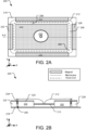
- FIGs. 2A and 2B represent different views of a portion of another example multi-magnet speaker 200.
- the multi-magnet speaker 200 is generally rectangular in shape and includes five magnets.
- Four of the magnets are arranged external to a perimeter formed by a voice coil 208 and are therefore referred to as outer magnets 204, 228, 230, and 232.
- Each of the outer magnets 204, 228, 230, and 232 is arranged to be parallel with and proximal to a corresponding one of the four sides of a bottom plate 218.
- a fifth one of the magnets (e.g., 202) is arranged internal to the perimeter formed by the voice coil 208 is therefore referred to as the inner magnet 202.
- the inner magnet 202 and the outer magnets 204, 228, 230, and 232 are arranged on the bottom plate 218 and sized and spaced such that there exists a gap 206 that forms a perimeter around the inner magnet 202 separating the inner magnet 202 from the outer magnets 204, 228, 230, and 232.
- the inner magnet 202 includes an annular-shaped cavity near its center, and a spider 210 is suspended by a side surface of the inner magnet 202 within the annular-shaped cavity.
- FIG. 2A also illustrates an outer perimeter of a membrane 212; however, the membrane 212 is shown transparent so as to permit visibility of the underlying components - e.g., the spider 210, the inner magnet 202, the gap 206, and the outer magnets 204, 228, 230, and 232 (which each partially underlies the membrane 212).
- the multi-magnet speaker 200 includes a housing with properties the same or similar to those shown and described with respect to FIG. 1B (e.g., housing 120), the housing is not shown in either of FIGs. 2A or 2B .
- FIG. 2B illustrates a cross-sectional view of the multi-magnet speaker 200 of FIG. 2A taken along the X-Z plane.
- This view shows two of the outer magnets 228 and 232 on opposite sides of the inner magnet 202.
- the gap 206 separates the inner magnet 202 from the outer magnets 204, 228, 230, and 232, and the voice coil 208 is secured to the membrane 212 (e.g., by a bobbin or other mechanism) and suspended within the gap 206.
- the voice coil 208 coils about the Z-axis making multiple turns about the inner magnet 202.
- the spider 210 is suspended above the bottom plate 218 by the inner magnet 202 and has a center that is secured to a central portion of the membrane 212.
- the multi-magnet speaker 200 further includes a top plate 220 with multiple individual pieces.
- the top plate 220 has five individual pieces each sized and shaped to correspond to and vertically align with a corresponding one of the five magnets. Gaps between the individual pieces of the top plate 220 correspond to the gap 206 as well as the various gaps between the outer magnets 204, 228, 230, and 232.
- the inner magnet 202 has a larger x-direction thickness than the outer magnets 204, 228, 230, and 232. This is in contrast with FIG. 1 , where the inner magnet 104 has a smaller x-direction thickness than the outer magnet 102.
- the relative sizes of the inner and outer magnets may differ depending on design constraints, motor strength needs, and cost concerns.
- the one or more outer magnets e.g., outer magnets 204, 228, 230, and 232
- the one or more outer magnets are arranged around the perimeter of the bottom plate 218 (as shown), but in other cases this arrangement extends beyond the perimeter of the bottom plate 218. This may, for example, be beneficial when a diameter of the speaker housing (not shown) is larger than the diameter of the bottom plate 218 (e.g., such as in an especially thin speaker design). Such a design may facilitate a reduction in the z-thickness of the speaker without compromising the strength of magnetic flux interacting with the voice coil 208.
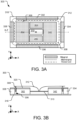
- FIGs. 3A and 3B represent different views of a portion of another example multi-magnet speaker 300.
- the multi-magnet speaker 300 is generally rectangular and includes eight magnets (e.g., 302, 304, 332, 334, 336, 338, 340, and 342.)
- Four of the magnets are arranged external to a perimeter formed by a voice coil 308 and are therefore referred to as outer magnets 332, 334, 336, and 338.
- Each of the outer magnets 332, 334, 336, and 338 is arranged to be parallel with and proximal to a corresponding one of the four sides of a bottom plate 318.
- Four other magnets are internal to the perimeter formed by the voice coil 308 and are therefore referred to as inner magnets 302, 304, 340, and 342.
- the inner magnets 302, 304, 340, and 342 and the outer 332, 334, 336, and 338 are arranged on the bottom plate 318 and sized and spaced such that there exists a gap 306 that forms a perimeter around the inner magnets 302, 304, 340, and 342 that separates the inner magnets 302, 304, 340, and 342 from the outer magnets 332, 334, 336, and 338.
- the inner magnets 302, 304, 340, and 342 are arranged to leave a rectangular cavity in a central portion of the multi-magnetic speaker 300, and a spider 310 is suspended in this cavity between side surfaces of the inner magnets 302, 304, 340, and 342.
- FIG. 3A also illustrates an outer perimeter of a membrane 312, which is shown transparent so as to permit visibility of the underlying components.
- the multi-magnet speaker 300 may include a housing with properties the same or similar to those shown and described with respect to FIG. 1B (e.g., housing 120), the housing is not shown in either of FIGs. 3A or 3B .
- FIG. 3B illustrates a cross-sectional view of the multi-magnet speaker 300 of FIG. 3A taken along the X-Z plane.
- This view shows two of the outer magnets 334 and 338 on opposite sides of the inner magnets 302 and 342.
- the voice coil 308 is secured to the membrane 312 (e.g., by a bobbin or other mechanism) and suspended within the gap 306, while the spider 310 is suspended above the bottom plate 318 by side surface of the inner magnets 302 and 342 (and also by side surface of the inner magnets 304 and 340 as shown in FIG. 3A ).
- the spider 310 has a center that is secured to a central portion of the membrane 312.
- the multi-magnet speaker 300 further includes a top plate 320 with multiple individual pieces.
- the top plate 320 has five individual pieces. One of the pieces is sized and shaped to cover the inner magnets 302, 304, 340, and 342, while the remaining four pieces are each sized and shaped to cover a corresponding one of the outer magnets 332, 334, 336, and 338. Gaps between the individual pieces of the top plate 320 correspond to the gap 306 as well as the various gaps between the outer magnets 332, 334, 336, and 338.
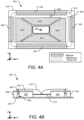
- FIG. 4A represents a top-down view of a portion of still another example multi-magnet speaker 400.
- the multi-magnet speaker 400 includes a multi-magnet structure formed by four inner magnets 402, 404, 440, and 442 and four outer magnets 432, 434, 436, and 438 arranged on a bottom plate 418.
- the inner magnets and outer magnets are arranged on opposite sides of a voice coil 408, which is suspended from a membrane 412 (shown transparent to permit visibility of underlying components) within a gap 406 between the inner magnets 402, 404, 440, and 442 and the outer magnets 432, 434, 436, and 438.
- the inner magnets 402, 404, 440, and 442 are arranged to form a rectangular cavity in a central portion of the multi-magnetic speaker 400, and a spider 410 is suspended in the cavity by side surfaces of the inner magnets 402, 404, 440, and 442.
- the membrane 412 has a center that is secured to a center of the spider 410.
- the multi-magnet speaker 400 includes a housing with properties the same or similar to those shown and described with respect to FIG. 1B (e.g., housing 120), the housing is not shown in either of FIGs. 4A or 4B .
- FIG. 4B represents a cross-sectional view of the multi-magnet speaker 400 of FIG. 4A taken along the X-Z plane.
- FIG. 4B not described explicitly herein may be the same or similar to those described above with respect to FIG. 3B .
- FIG. 5A represents a top-down view of a portion of yet another example multi-magnet speaker 500.
- the multi-magnet speaker 500 includes a multi-magnet structure formed by two inner magnets 502 and 504 and four outer magnets 532, 534, 536, and 538 arranged on a bottom plate 518.
- the inner magnets 502 and 504 are shown to be trapezoidal; but are, in another implementation, triangular.
- the four outer magnets 532, 534, 536, and 538 are rectangular.
- the inner magnets 502 and 504 and outer magnets 532, 534, 536, and 538 are arranged on opposite sides of a voice coil 508, which is suspended from a membrane 512 (shown transparent to permit visibility of underlying components) within a gap 506 between the inner magnets 502, 504 and the outer magnets 532, 534, 536, and 538.
- the membrane 512 has a center that is secured to a center of a spider 510, which is itself suspended by sidewalls of the inner magnets 502 and 504.
- FIG. 5B represents a cross-sectional view of the multi-magnet speaker 500 of FIG. 5A taken along the X-Z plane.
- FIG. 5B not described explicitly herein may be the same or similar to those described above with respect to FIG. 3B .
- the same or similar technology leveraged in the designs of FIGS. 1-5 may be implemented in a number of different multi-magnet speaker designs other than those specific designs disclosed herein, including designs with a greater number of magnets and/or differently-shaped magnets than those exemplary designs disclosed herein.
- FIG. 6 illustrates example operations 600 for assembling a multi-magnet speaker.
- a first attachment operation 602 attaches a central portion of a membrane to a spider.
- the spider serves the function of stabilizing the membrane toward and away from a multi-magnet structure as the membrane moves under force generated by a multi-magnet structure and a voice coil.
- Another attachment operation 604 attaches a voice coil to the membrane such that the voice coil forms a perimeter around the central portion of the membrane attached to the spider.
- a securing operation 606 secures an outer perimeter of the membrane to a speaker housing. When the outer perimeter is secured, that the membrane extends over a multi-magnet structure and the voice coil is suspended within a gap between magnets of the multi-magnet structure.
- a suspension operation 608 suspends the spider within a cavity formed by one or more inner magnets of the multi-magnet structure.
- the implementations described herein are implemented as logical steps in one or more computer systems.
- the logical operations may be implemented (1) as a sequence of processor-implemented steps executing in one or more computer systems and (2) as interconnected machine or circuit modules within one or more computer systems.
- the implementation is a matter of choice, dependent on the performance requirements of the computer system being utilized. Accordingly, the logical operations making up the implementations described herein are referred to variously as operations, steps, objects, or modules.
- logical operations may be performed in any order, unless explicitly claimed otherwise or a specific order is inherently necessitated by the claim language.
Landscapes
- Engineering & Computer Science (AREA)
- Physics & Mathematics (AREA)
- Acoustics & Sound (AREA)
- Signal Processing (AREA)
- Multimedia (AREA)
- Audible-Bandwidth Dynamoelectric Transducers Other Than Pickups (AREA)
Description
- This application relates to speakers, and more specifically high-efficiency speakers.
- Within a speaker, pulses of electricity are typically passed through a voice coil positioned in proximity of a permanent magnet. As the magnetic field generated by the voice coil rapidly changes along with received current pulses of varying magnitude, the voice coil is attracted to and repelled from the permanent magnet. These vibrations of the voice coil are amplified by the motion of a speaker membrane that moves in and out to pump sound waves into the air. In general, speaker volume is proportional to the excursion range of the speaker membrane, and sound quality is impacted by the evenness of movement of the speaker membrane toward and away from the magnet. Rigid movement - like a piston - tends to provide higher sound quality while movement that is less even (e.g., wobbling due to poor membrane suspension) reduces sound quality.
- In traditional large speakers, a flexible, corrugated support called a spider is used to suspend the voice coil in place within a basket housing. In a different variant, the spider can attach to the membrane (e.g., diaphragm) on one side and a basket or magnet on the other side, providing stabilization for the membrane throughout its corresponding range of motion. In contrast to these traditional large speakers, modern mini and micro speakers tend to feature thinner membranes that better respond to the flux ranges of smaller magnets. Often, the compact arrangement of mini and micro speakers does not permit a spider to be included to stabilize the membrane because, in many cases, the traditional location of the spider is occupied by magnet material as a result of spacing constraints.
US 4,327,257 describes an electro-acoustical transducer has a voice coil assembly, a diaphragm coupled to the voice coil, a permanent magnet arrangement for providing a magnetic field in an air gap, and support means for axially centering the voice coil assembly in the air gap and means for maintaining axial alignment of the voice coil assembly during movement thereof. The permanent magnet arrangement comprises two concentrically disposed permanent magnets whose adjacent faces are oppositely poled. In some embodiments, the support means comprises a rigid diaphragm disposed between rigid top and bottom spiders and at least one slideably mounted rod connecting the two spiders. - The invention is set out in the appended set of claims.
- Implementations disclosed herein provide a high-efficiency speaker with a multi-magnet structure including at least an inner magnet and an outer magnet. A voice coil is suspended from a membrane into a gap between the inner magnet and the outer magnet, and a spider is attached to the membrane and suspended at least partially by the inner magnet. The spider stabilizes the membrane throughout a range of motion occurring responsive to forces generated by the voice coil and the multi-magnet structure.
- This Summary is provided to introduce a selection of concepts in a simplified form that are further described below in the Detailed Description. This Summary is not intended to identify key features or essential features of the claimed subject matter, nor is it intended to be used to limit the scope of the claimed subject matter.
- Other implementations are also described and recited herein.
-
-
FIG. 1A illustrates a top-down view of an example multi-magnet speaker. -
FIG. 1B illustrates a cross-sectional view of the multi-magnet speaker ofFIG. 1A . -
FIG. 2A illustrates a top-down view of another example multi-magnet speaker. -
FIG. 2B illustrates a cross-sectional view of the multi-magnet speaker ofFIG. 2A . -
FIG. 3A illustrates a top-down view of another example multi-magnet speaker. -
FIG. 3B illustrates a cross-sectional view of the multi-magnet speaker ofFIG. 3A . -
FIG. 4A illustrates a top-down view of another example multi-magnet speaker. -
FIG. 4B illustrates a cross-sectional view of the multi-magnet speaker ofFIG. 4A . -
FIG. 5A illustrates a top-down view of another example multi-magnet speaker. -
FIG. 5B illustrates a cross-sectional view of the multi-magnet speaker ofFIG. 5A . -
FIG. 6 illustrates example operations for assembling a multi-magnet speaker. - The following disclosure provides multiple high-efficiency multi-magnet speaker designs. Although these designs may be implemented in speakers of any size, the disclosed designs may be particularly useful in addressing the design shortcomings of modern mini speakers.
- In some mini speaker designs, a voice coil is wound around a permanent magnet as a space-saving measure; however, this design places the permanent magnet in the location where a spider may traditionally be included (e.g., in traditional large speaker designs) to stabilize a center of the membrane relative to the voice coil. Since the center of the membrane is not secured to a spider or to the voice coil, air pressure serves as a key source of stability for the membrane and additional structure may be included to prevent side-to-side membrane wobbling. More specifically, some mini speaker designs feature a plastic ring secured about an outer-perimeter of the membrane. However, a plastic ring adds weight, reducing speaker efficiency. To help maximize membrane excursion (and therefore volume), mini speakers may feature a thinner membrane that better responds to small Lorentz forces than the thicker membranes typically included in larger speakers. However, the use of a thinner membrane correlates with a drop in the sensitivity of the speaker and a drop in the overall output for a given input power. A common technique to counteract this is to use a larger amplifier to drive the speaker and materials that have better thermal capabilities to handle an increase in voice coil temperature that occurs as a result of the increased amplification. However, larger amplifiers draw increased power, which can be problematic in battery-operated speakers that may, as a result, require recharge sooner.
- The herein disclosed technology provides an increase in speaker efficiency that may permit mini speakers to be driven with smaller amplifiers without a trade-off in volume or sound quality. This increased efficiency may translate to better sound and/or decreased power consumption as compared to similar-sized speakers that include larger amplifiers and/or speakers that do not utilize a spider to stabilize the membrane.
-
FIG. 1A and 1B represent different views of an examplemulti-magnet speaker 100.FIG. 1A is a top-down view of themulti-magnet speaker 100, which includes two annular-shaped magnets. Aninner magnet 104 is arranged within an aperture of theouter magnet 102. Theouter magnet 102 and theinner magnet 104 are arranged on a bottom plate 118 (shown inFIG 1B ), and themagnets gap 106 between theouter magnet 102 and theinner magnet 104. Avoice coil 108 is positioned within thegap 106 and is positioned to coil one or multiple times about the inner magnet 104 (around the Z-axis perpendicular to the page). - The
multi-magnet speaker 100 includes aspider 110 suspended within an aperture of theinner magnet 104. The top-down view ofFIG. 1A illustrates an outer perimeter of amembrane 112, which is shown transparent so as to permit visibility of the underlying components - e.g., thespider 110, theinner magnet 104, thegap 106, and an inner portion of theouter magnet 102. For clarity of illustration, aspects of a housing (visible ashousing 120 inFIG. 1B ) are not shown inFIG. 1A . -
FIG. 1B illustrates a cross-sectional view of themulti-magnet speaker 100 ofFIG. 1A taken along the X-Z plane. This view shows several additional features not visible inFIG. 1A . Theinner magnet 104 and theouter magnet 102 are shown arranged on thebottom plate 118, which is attached to ahousing 120. Thevoice coil 108 is secured to themembrane 112 by abobbin 114 and suspended by thebobbin 114 andmembrane 112 within thegap 106 between theinner magnet 104 and theouter magnet 102. Themembrane 112 has an outer perimeter secured to a basket 122 (e.g., an annular basket), which is attached to thehousing 120. A central portion of themembrane 112 is attached to a central portion of the spider 110 (e.g., via adhesive), and thespider 110 is itself suspended above thebottom plate 118 within an aperture of theinner magnet 104. This suspension of thespider 110 within theinner magnet 104 may be achieved in a variety of different ways such as by utilizing an adhesive to attach thespider 110 directly to a sidewall of theinner magnet 104 or by using an interim layer that provides a stable adhesive surface, such as a by applying adhesive to a thin, plastic-like holder that is bonded to a sidewall of theinner magnet 104 and the perimeter of thespider 110. - The top plate 124 (shown in
FIG. 1B but not inFIG. 1A ) includes two pieces - one sized and shaped to cover theinner magnet 104 and one sized and shaped to cover theouter magnet 102. Gaps between the pieces of thetop plate 124 vertically align - along the Z-axis - with thegap 106, which receives thevoice coil 108. Additionally, the gaps between the pieces of thetop plate 124 also vertically align with thespider 110. In one implementation, theinner magnet 104 and theouter magnet 102 are made from ferrite or powerful neodymium, while thetop plate 124 and thebottom plate 118 are made from soft iron. - This multi-magnet design provides enhanced air flow as compared to single-magnet speakers. Various arrows in
FIG. 1B indicate available ventilation paths between themembrane 112,inner magnet 104,outer magnet 102, andhousing 120. (Note: thebobbin 114 is air-permeable). The enhanced air flow offered by this design provides greater sound pressure which translates to a large excursion range for themembrane 112 as compared to existing designs. - Further, the disclosed multi-magnet design makes it possible to include the
spider 110 for membrane stabilization. Thespider 110 is included in acentral region 126 that is, in traditional mini speakers, occupied by magnetic material. The presently-disclosed design effectively displaces this magnetic material to an opposite side of thevoice coil 108. The width of thegap 106 and corresponding proximity between thevoice coil 108 and the two magnets 102,104 may vary in different implementations based on magnetic properties but is generally such as to ensure that thevoice coil 108 is subjected to a sufficient amount of flux (e.g., identical flux as in single-magnet speaker designs) to cause vibrations of predetermined magnitude. -
FIGs. 2A and 2B represent different views of a portion of another examplemulti-magnet speaker 200. As shown in top-down viewFIG. 2A , themulti-magnet speaker 200 is generally rectangular in shape and includes five magnets. Four of the magnets are arranged external to a perimeter formed by avoice coil 208 and are therefore referred to asouter magnets outer magnets bottom plate 218. A fifth one of the magnets (e.g., 202) is arranged internal to the perimeter formed by thevoice coil 208 is therefore referred to as theinner magnet 202. - The
inner magnet 202 and theouter magnets bottom plate 218 and sized and spaced such that there exists agap 206 that forms a perimeter around theinner magnet 202 separating theinner magnet 202 from theouter magnets inner magnet 202 includes an annular-shaped cavity near its center, and aspider 210 is suspended by a side surface of theinner magnet 202 within the annular-shaped cavity. - The top-down view of
FIG. 2A also illustrates an outer perimeter of amembrane 212; however, themembrane 212 is shown transparent so as to permit visibility of the underlying components - e.g., thespider 210, theinner magnet 202, thegap 206, and theouter magnets multi-magnet speaker 200 includes a housing with properties the same or similar to those shown and described with respect toFIG. 1B (e.g., housing 120), the housing is not shown in either ofFIGs. 2A or 2B . -
FIG. 2B illustrates a cross-sectional view of themulti-magnet speaker 200 ofFIG. 2A taken along the X-Z plane. This view shows two of theouter magnets inner magnet 202. Thegap 206 separates theinner magnet 202 from theouter magnets voice coil 208 is secured to the membrane 212 (e.g., by a bobbin or other mechanism) and suspended within thegap 206. In one implementation, thevoice coil 208 coils about the Z-axis making multiple turns about theinner magnet 202. - As shown in
FIG. 2B , thespider 210 is suspended above thebottom plate 218 by theinner magnet 202 and has a center that is secured to a central portion of themembrane 212. - The
multi-magnet speaker 200 further includes atop plate 220 with multiple individual pieces. In one implementation, thetop plate 220 has five individual pieces each sized and shaped to correspond to and vertically align with a corresponding one of the five magnets. Gaps between the individual pieces of thetop plate 220 correspond to thegap 206 as well as the various gaps between theouter magnets inner magnet 202 has a larger x-direction thickness than theouter magnets FIG. 1 , where theinner magnet 104 has a smaller x-direction thickness than theouter magnet 102. As illustrated by these figures, the relative sizes of the inner and outer magnets may differ depending on design constraints, motor strength needs, and cost concerns. In some implementations, the one or more outer magnets (e.g.,outer magnets bottom plate 218. This may, for example, be beneficial when a diameter of the speaker housing (not shown) is larger than the diameter of the bottom plate 218 (e.g., such as in an especially thin speaker design). Such a design may facilitate a reduction in the z-thickness of the speaker without compromising the strength of magnetic flux interacting with thevoice coil 208. -
FIGs. 3A and 3B represent different views of a portion of another examplemulti-magnet speaker 300. As shown in top-down viewFIG. 3A , themulti-magnet speaker 300 is generally rectangular and includes eight magnets (e.g., 302, 304, 332, 334, 336, 338, 340, and 342.) Four of the magnets are arranged external to a perimeter formed by avoice coil 308 and are therefore referred to asouter magnets outer magnets bottom plate 318. Four other magnets are internal to the perimeter formed by thevoice coil 308 and are therefore referred to asinner magnets - The
inner magnets bottom plate 318 and sized and spaced such that there exists agap 306 that forms a perimeter around theinner magnets inner magnets outer magnets inner magnets multi-magnetic speaker 300, and aspider 310 is suspended in this cavity between side surfaces of theinner magnets - The top-down view of
FIG. 3A also illustrates an outer perimeter of amembrane 312, which is shown transparent so as to permit visibility of the underlying components. Although themulti-magnet speaker 300 may include a housing with properties the same or similar to those shown and described with respect toFIG. 1B (e.g., housing 120), the housing is not shown in either ofFIGs. 3A or 3B . -
FIG. 3B illustrates a cross-sectional view of themulti-magnet speaker 300 ofFIG. 3A taken along the X-Z plane. This view shows two of theouter magnets inner magnets voice coil 308 is secured to the membrane 312 (e.g., by a bobbin or other mechanism) and suspended within thegap 306, while thespider 310 is suspended above thebottom plate 318 by side surface of theinner magnets 302 and 342 (and also by side surface of theinner magnets FIG. 3A ). Thespider 310 has a center that is secured to a central portion of themembrane 312. - The
multi-magnet speaker 300 further includes atop plate 320 with multiple individual pieces. In one implementation, thetop plate 320 has five individual pieces. One of the pieces is sized and shaped to cover theinner magnets outer magnets top plate 320 correspond to thegap 306 as well as the various gaps between theouter magnets -
FIG. 4A represents a top-down view of a portion of still another examplemulti-magnet speaker 400. Themulti-magnet speaker 400 includes a multi-magnet structure formed by fourinner magnets outer magnets bottom plate 418. The inner magnets and outer magnets are arranged on opposite sides of avoice coil 408, which is suspended from a membrane 412 (shown transparent to permit visibility of underlying components) within agap 406 between theinner magnets outer magnets
Theinner magnets multi-magnetic speaker 400, and aspider 410 is suspended in the cavity by side surfaces of theinner magnets membrane 412 has a center that is secured to a center of thespider 410. Although themulti-magnet speaker 400 includes a housing with properties the same or similar to those shown and described with respect toFIG. 1B (e.g., housing 120), the housing is not shown in either ofFIGs. 4A or 4B . -
FIG. 4B represents a cross-sectional view of themulti-magnet speaker 400 ofFIG. 4A taken along the X-Z plane. Features ofFIG. 4B not described explicitly herein may be the same or similar to those described above with respect toFIG. 3B . -
FIG. 5A represents a top-down view of a portion of yet another examplemulti-magnet speaker 500. Themulti-magnet speaker 500 includes a multi-magnet structure formed by twoinner magnets outer magnets bottom plate 518. Theinner magnets outer magnets inner magnets outer magnets voice coil 508, which is suspended from a membrane 512 (shown transparent to permit visibility of underlying components) within agap 506 between theinner magnets outer magnets membrane 512 has a center that is secured to a center of aspider 510, which is itself suspended by sidewalls of theinner magnets -
FIG. 5B represents a cross-sectional view of themulti-magnet speaker 500 ofFIG. 5A taken along the X-Z plane. Features ofFIG. 5B not described explicitly herein may be the same or similar to those described above with respect toFIG. 3B . The same or similar technology leveraged in the designs ofFIGS. 1-5 may be implemented in a number of different multi-magnet speaker designs other than those specific designs disclosed herein, including designs with a greater number of magnets and/or differently-shaped magnets than those exemplary designs disclosed herein. -
FIG. 6 illustratesexample operations 600 for assembling a multi-magnet speaker. Afirst attachment operation 602 attaches a central portion of a membrane to a spider. When the membrane and spider are integrated within a speaker, the spider serves the function of stabilizing the membrane toward and away from a multi-magnet structure as the membrane moves under force generated by a multi-magnet structure and a voice coil. - Another
attachment operation 604 attaches a voice coil to the membrane such that the voice coil forms a perimeter around the central portion of the membrane attached to the spider. A securingoperation 606 secures an outer perimeter of the membrane to a speaker housing. When the outer perimeter is secured, that the membrane extends over a multi-magnet structure and the voice coil is suspended within a gap between magnets of the multi-magnet structure. Asuspension operation 608 suspends the spider within a cavity formed by one or more inner magnets of the multi-magnet structure. - The implementations described herein are implemented as logical steps in one or more computer systems. The logical operations may be implemented (1) as a sequence of processor-implemented steps executing in one or more computer systems and (2) as interconnected machine or circuit modules within one or more computer systems. The implementation is a matter of choice, dependent on the performance requirements of the computer system being utilized. Accordingly, the logical operations making up the implementations described herein are referred to variously as operations, steps, objects, or modules. Furthermore, it should be understood that logical operations may be performed in any order, unless explicitly claimed otherwise or a specific order is inherently necessitated by the claim language.
Claims (11)
- A speaker (100) comprising:a housing (120) including a bottom plate (118);a multi-magnet structure including at least an inner magnet (104) and an outer magnet (102);a voice coil (108) suspended from a membrane (112) into a gap (106) formed between the inner magnet (104) and the outer magnet (102); anda spider (110) attached to the membrane (112) and suspended at least partially by the inner magnet (104), the spider (110) configured to stabilize the membrane (112) throughout a range of movement occurring in response to forces generated by the voice coil (108) and the multi-magnet structure;wherein the inner magnet (104) comprises multiple inner magnets and the outer magnet (102) comprises multiple outer magnets, the multiple outer magnets being positioned at locations external to a perimeter of the voice coil and the multiple inner magnets being positioned at locations internal to a perimeter of the voice coil, wherein each of the multiple outer magnets are arranged on the bottom plate (118) attached to the housing (120), the spider (110) and voice coil (108) being suspended above the bottom plate (118);wherein the multiple outer magnets extend beyond a perimeter of the bottom plate (218), and wherein the multiple outer magnets extend into the housing (120).
- The speaker of claim 1, where the spider is suspended within an aperture of the inner magnet.
- The speaker of claim 1, wherein the voice coil is suspended in the gap that separates the multiple inner magnets from the multiple outer magnets.
- The speaker of claim 1, wherein the spider is suspended by the multiple inner magnets.
- The speaker of claim 1, wherein the outer magnet has a greater cross-sectional thickness than the inner magnet along an axis perpendicular to an axis of motion for the membrane.
- The speaker of claim 1, wherein the membrane completely overlaps the inner magnet.
- The speaker of claim 1, wherein the membrane overlaps an inner portion of the outer magnet but does not overlap an outer portion of the outer magnet.
- The speaker of claim 1, wherein the inner magnet rests within an aperture of the outer magnet.
- A method comprising:suspending a voice coil (108) from a membrane (112) and into a gap (106) of a multi-magnet structure, the gap (106) formed between at least one inner magnet (104) and least one outer magnet (102); andsuspending a spider (110) against at least one wall of the at least one inner magnet (104), the spider (110) attached to the membrane (112) and configured to stabilize the membrane (112) throughout a range of movement occurring in response to forces generated by the voice coil (106) and the multi-magnet structure;wherein the inner magnet (104) comprises multiple inner magnets and the outer magnet (102) comprises multiple outer magnets, the multiple outer magnets being positioned at locations external to a perimeter of the voice coil and the multiple inner magnets being positioned at locations internal to a perimeter of the voice coil, wherein each of the multiple outer magnets are arranged on a bottom plate (118) attached to a housing (120), the spider (110) and voice coil (108) being suspended above the bottom plate (118);wherein the multiple outer magnets extend beyond a perimeter of the bottom plate (218), and wherein the multiple outer magnets extend into the housing (120).
- The method of claim 9, where the spider is suspended within an aperture formed within the at least one inner magnet.
- The method of claim 9, wherein the gap separates the multiple inner magnets from the multiple outer magnets.
Applications Claiming Priority (2)
| Application Number | Priority Date | Filing Date | Title |
|---|---|---|---|
| US15/987,440 US10492005B1 (en) | 2018-05-23 | 2018-05-23 | High-efficiency speaker with multi-magnet structure |
| PCT/US2019/030987 WO2019226323A1 (en) | 2018-05-23 | 2019-05-07 | High-efficiency speaker with multi-magnet structure |
Publications (2)
| Publication Number | Publication Date |
|---|---|
| EP3797526A1 EP3797526A1 (en) | 2021-03-31 |
| EP3797526B1 true EP3797526B1 (en) | 2024-06-26 |
Family
ID=66554540
Family Applications (1)
| Application Number | Title | Priority Date | Filing Date |
|---|---|---|---|
| EP19724714.1A Active EP3797526B1 (en) | 2018-05-23 | 2019-05-07 | High-efficiency speaker with multi-magnet structure |
Country Status (4)
| Country | Link |
|---|---|
| US (1) | US10492005B1 (en) |
| EP (1) | EP3797526B1 (en) |
| CN (1) | CN112154675A (en) |
| WO (1) | WO2019226323A1 (en) |
Families Citing this family (5)
| Publication number | Priority date | Publication date | Assignee | Title |
|---|---|---|---|---|
| CN114125662B (en) | 2020-09-01 | 2026-01-23 | 华为技术有限公司 | Speaker and electronic equipment |
| CN114339553A (en) * | 2020-10-09 | 2022-04-12 | 万魔声学(湖南)科技有限公司 | 360-degree sound production loudspeaker |
| EP4195693A1 (en) * | 2021-12-09 | 2023-06-14 | Harman Becker Automotive Systems GmbH | Loudspeaker |
| CN217904644U (en) * | 2022-05-16 | 2022-11-25 | 华为技术有限公司 | Loudspeaker and electronic equipment |
| US12075229B2 (en) | 2022-09-12 | 2024-08-27 | Zachary Arthur Mehrbach | Triangular or hexagonal angled magnet shape for planar magnetic or “isodynamic” drivers |
Family Cites Families (21)
| Publication number | Priority date | Publication date | Assignee | Title |
|---|---|---|---|---|
| US4327257A (en) | 1979-09-10 | 1982-04-27 | Schwartz Leslie H | Alignment device for electro-acoustical transducers |
| WO1998054924A2 (en) | 1997-05-31 | 1998-12-03 | Ultra Research, Inc. | Ultra structure subwoofer |
| DE10303030A1 (en) * | 2003-01-25 | 2004-08-05 | Norman Gerkinsmeyer | driver |
| JP3896970B2 (en) * | 2003-01-31 | 2007-03-22 | 松下電器産業株式会社 | Speaker |
| US6865282B2 (en) | 2003-05-01 | 2005-03-08 | Richard L. Weisman | Loudspeaker suspension for achieving very long excursion |
| US7706563B2 (en) * | 2005-12-19 | 2010-04-27 | Harman International Industries, Incorporated | Concentric radial ring motor |
| JP4912922B2 (en) | 2007-02-28 | 2012-04-11 | ミネベア株式会社 | Speaker |
| WO2008112176A2 (en) | 2007-03-09 | 2008-09-18 | One Systems Group Co., Ltd | Transducer motor structure and inside-only voice coil for use in loudspeakers |
| CN101321409B (en) | 2007-06-06 | 2011-11-30 | 葛锦明 | Double magnetic circuit two-tone ring plate loudspeaker |
| US8682022B2 (en) | 2008-10-24 | 2014-03-25 | Jason Myles Cobb | Loudspeaker |
| CN101984678B (en) | 2010-11-18 | 2016-04-06 | 瑞声声学科技(深圳)有限公司 | Acoustical generator |
| US8649550B2 (en) | 2011-01-06 | 2014-02-11 | Aac Acoustic Technologies (Shenzhen) Co., Ltd. | Multi-magnet system and speaker using same |
| CN201967118U (en) | 2011-01-06 | 2011-09-07 | 瑞声光电科技(常州)有限公司 | Novel mini-type loudspeaker |
| KR20130089396A (en) * | 2012-02-02 | 2013-08-12 | 삼성전자주식회사 | Speaker with n-divided magnet structrue |
| CN202713601U (en) * | 2012-08-09 | 2013-01-30 | 郑全录 | Inner-outer magnetic loudspeaker |
| US8934657B2 (en) | 2013-02-07 | 2015-01-13 | Apple Inc. | Speaker magnet assembly with included spider |
| US9820038B2 (en) * | 2013-09-30 | 2017-11-14 | Apple Inc. | Waterproof speaker module |
| US9467783B2 (en) | 2013-10-25 | 2016-10-11 | Tymphany Worldwide Enterprises Limited | Low profile loudspeaker transducer |
| CN203968357U (en) * | 2014-06-05 | 2014-11-26 | 楼氏电子(北京)有限公司 | Magnetic assembly and the loud speaker that comprises this magnetic assembly |
| CN105228060A (en) * | 2014-06-05 | 2016-01-06 | 楼氏国际采购中心(马来西亚)私人有限公司 | Magnetic assembly and the loud speaker comprising this magnetic assembly |
| CN206686369U (en) * | 2016-11-14 | 2017-11-28 | 哈曼国际工业有限公司 | Loudspeaker |
-
2018
- 2018-05-23 US US15/987,440 patent/US10492005B1/en active Active
-
2019
- 2019-05-07 WO PCT/US2019/030987 patent/WO2019226323A1/en not_active Ceased
- 2019-05-07 EP EP19724714.1A patent/EP3797526B1/en active Active
- 2019-05-07 CN CN201980034283.2A patent/CN112154675A/en active Pending
Also Published As
| Publication number | Publication date |
|---|---|
| US20190364367A1 (en) | 2019-11-28 |
| CN112154675A (en) | 2020-12-29 |
| WO2019226323A1 (en) | 2019-11-28 |
| US10492005B1 (en) | 2019-11-26 |
| EP3797526A1 (en) | 2021-03-31 |
Similar Documents
| Publication | Publication Date | Title |
|---|---|---|
| US10492005B1 (en) | High-efficiency speaker with multi-magnet structure | |
| CN108533669B (en) | Space six-degree-of-freedom active and passive vibration isolation platform and method based on electromagnetic negative stiffness | |
| US9743192B2 (en) | Speaker and vibration control unit | |
| CN103597852B (en) | Electromechanical-electroacoustic transducer with low thickness and high stroke and method of manufacturing the same | |
| EP2512155B1 (en) | Low profile loudspeaker transducer | |
| JP5923798B2 (en) | Vibration generator | |
| EP3570559A1 (en) | High-quality electromagnetic speaker having improved accuracy of air gap | |
| US8781150B2 (en) | Multiple magnetic air gap motor | |
| EP2512153B1 (en) | Loudspeaker magnet assembly | |
| CN206686369U (en) | Loudspeaker | |
| WO2022166388A1 (en) | Sound producing device and earphone | |
| US8131005B2 (en) | Electrodynamic transducer including a dome with a ferrofluid suspension | |
| KR20120116369A (en) | Low profile loudspeaker suspension system | |
| KR20090028877A (en) | Electrodynamic electroacoustic transducer | |
| EP1788842A2 (en) | Speaker apparatus | |
| JP2016502323A (en) | Electromagnetic transducer and vibration control system | |
| CN115209318B (en) | Moving magnet type motor | |
| CN110235452B (en) | Speaker diaphragm and speaker device | |
| JP2001128287A (en) | Loudspeaker | |
| US20120155699A1 (en) | Speaker and yoke thereof | |
| CN205008213U (en) | Inertial -type vibration exciter of twin coil single action magnet structure based on forced -air cooling heat dissipation | |
| JP2001000043U (en) | Magnetic circuit for speaker | |
| JP2004502365A (en) | Small high-performance speaker | |
| US11245986B2 (en) | Electro-magnetic motor geometry with radial ring and axial pole magnet | |
| US20130343596A1 (en) | Speaker |
Legal Events
| Date | Code | Title | Description |
|---|---|---|---|
| STAA | Information on the status of an ep patent application or granted ep patent |
Free format text: STATUS: THE INTERNATIONAL PUBLICATION HAS BEEN MADE |
|
| PUAI | Public reference made under article 153(3) epc to a published international application that has entered the european phase |
Free format text: ORIGINAL CODE: 0009012 |
|
| STAA | Information on the status of an ep patent application or granted ep patent |
Free format text: STATUS: REQUEST FOR EXAMINATION WAS MADE |
|
| 17P | Request for examination filed |
Effective date: 20201023 |
|
| AK | Designated contracting states |
Kind code of ref document: A1 Designated state(s): AL AT BE BG CH CY CZ DE DK EE ES FI FR GB GR HR HU IE IS IT LI LT LU LV MC MK MT NL NO PL PT RO RS SE SI SK SM TR |
|
| AX | Request for extension of the european patent |
Extension state: BA ME |
|
| DAV | Request for validation of the european patent (deleted) | ||
| DAX | Request for extension of the european patent (deleted) | ||
| RAP3 | Party data changed (applicant data changed or rights of an application transferred) |
Owner name: MICROSOFT TECHNOLOGY LICENSING, LLC |
|
| STAA | Information on the status of an ep patent application or granted ep patent |
Free format text: STATUS: EXAMINATION IS IN PROGRESS |
|
| 17Q | First examination report despatched |
Effective date: 20211214 |
|
| GRAP | Despatch of communication of intention to grant a patent |
Free format text: ORIGINAL CODE: EPIDOSNIGR1 |
|
| STAA | Information on the status of an ep patent application or granted ep patent |
Free format text: STATUS: GRANT OF PATENT IS INTENDED |
|
| GRAJ | Information related to disapproval of communication of intention to grant by the applicant or resumption of examination proceedings by the epo deleted |
Free format text: ORIGINAL CODE: EPIDOSDIGR1 |
|
| STAA | Information on the status of an ep patent application or granted ep patent |
Free format text: STATUS: EXAMINATION IS IN PROGRESS |
|
| GRAP | Despatch of communication of intention to grant a patent |
Free format text: ORIGINAL CODE: EPIDOSNIGR1 |
|
| STAA | Information on the status of an ep patent application or granted ep patent |
Free format text: STATUS: GRANT OF PATENT IS INTENDED |
|
| INTG | Intention to grant announced |
Effective date: 20231109 |
|
| INTC | Intention to grant announced (deleted) | ||
| INTG | Intention to grant announced |
Effective date: 20231205 |
|
| P01 | Opt-out of the competence of the unified patent court (upc) registered |
Effective date: 20231211 |
|
| GRAS | Grant fee paid |
Free format text: ORIGINAL CODE: EPIDOSNIGR3 |
|
| GRAA | (expected) grant |
Free format text: ORIGINAL CODE: 0009210 |
|
| STAA | Information on the status of an ep patent application or granted ep patent |
Free format text: STATUS: THE PATENT HAS BEEN GRANTED |
|
| AK | Designated contracting states |
Kind code of ref document: B1 Designated state(s): AL AT BE BG CH CY CZ DE DK EE ES FI FR GB GR HR HU IE IS IT LI LT LU LV MC MK MT NL NO PL PT RO RS SE SI SK SM TR |
|
| REG | Reference to a national code |
Ref country code: GB Ref legal event code: FG4D |
|
| REG | Reference to a national code |
Ref country code: CH Ref legal event code: EP |
|
| REG | Reference to a national code |
Ref country code: DE Ref legal event code: R096 Ref document number: 602019054184 Country of ref document: DE |
|
| PG25 | Lapsed in a contracting state [announced via postgrant information from national office to epo] |
Ref country code: BG Free format text: LAPSE BECAUSE OF FAILURE TO SUBMIT A TRANSLATION OF THE DESCRIPTION OR TO PAY THE FEE WITHIN THE PRESCRIBED TIME-LIMIT Effective date: 20240626 |
|
| PG25 | Lapsed in a contracting state [announced via postgrant information from national office to epo] |
Ref country code: HR Free format text: LAPSE BECAUSE OF FAILURE TO SUBMIT A TRANSLATION OF THE DESCRIPTION OR TO PAY THE FEE WITHIN THE PRESCRIBED TIME-LIMIT Effective date: 20240626 Ref country code: FI Free format text: LAPSE BECAUSE OF FAILURE TO SUBMIT A TRANSLATION OF THE DESCRIPTION OR TO PAY THE FEE WITHIN THE PRESCRIBED TIME-LIMIT Effective date: 20240626 |
|
| REG | Reference to a national code |
Ref country code: LT Ref legal event code: MG9D |
|
| PG25 | Lapsed in a contracting state [announced via postgrant information from national office to epo] |
Ref country code: GR Free format text: LAPSE BECAUSE OF FAILURE TO SUBMIT A TRANSLATION OF THE DESCRIPTION OR TO PAY THE FEE WITHIN THE PRESCRIBED TIME-LIMIT Effective date: 20240927 |
|
| PG25 | Lapsed in a contracting state [announced via postgrant information from national office to epo] |
Ref country code: LV Free format text: LAPSE BECAUSE OF FAILURE TO SUBMIT A TRANSLATION OF THE DESCRIPTION OR TO PAY THE FEE WITHIN THE PRESCRIBED TIME-LIMIT Effective date: 20240626 |
|
| PG25 | Lapsed in a contracting state [announced via postgrant information from national office to epo] |
Ref country code: NO Free format text: LAPSE BECAUSE OF FAILURE TO SUBMIT A TRANSLATION OF THE DESCRIPTION OR TO PAY THE FEE WITHIN THE PRESCRIBED TIME-LIMIT Effective date: 20240926 Ref country code: LV Free format text: LAPSE BECAUSE OF FAILURE TO SUBMIT A TRANSLATION OF THE DESCRIPTION OR TO PAY THE FEE WITHIN THE PRESCRIBED TIME-LIMIT Effective date: 20240626 Ref country code: HR Free format text: LAPSE BECAUSE OF FAILURE TO SUBMIT A TRANSLATION OF THE DESCRIPTION OR TO PAY THE FEE WITHIN THE PRESCRIBED TIME-LIMIT Effective date: 20240626 Ref country code: GR Free format text: LAPSE BECAUSE OF FAILURE TO SUBMIT A TRANSLATION OF THE DESCRIPTION OR TO PAY THE FEE WITHIN THE PRESCRIBED TIME-LIMIT Effective date: 20240927 Ref country code: FI Free format text: LAPSE BECAUSE OF FAILURE TO SUBMIT A TRANSLATION OF THE DESCRIPTION OR TO PAY THE FEE WITHIN THE PRESCRIBED TIME-LIMIT Effective date: 20240626 Ref country code: BG Free format text: LAPSE BECAUSE OF FAILURE TO SUBMIT A TRANSLATION OF THE DESCRIPTION OR TO PAY THE FEE WITHIN THE PRESCRIBED TIME-LIMIT Effective date: 20240626 Ref country code: RS Free format text: LAPSE BECAUSE OF FAILURE TO SUBMIT A TRANSLATION OF THE DESCRIPTION OR TO PAY THE FEE WITHIN THE PRESCRIBED TIME-LIMIT Effective date: 20240926 |
|
| PG25 | Lapsed in a contracting state [announced via postgrant information from national office to epo] |
Ref country code: NL Free format text: LAPSE BECAUSE OF FAILURE TO SUBMIT A TRANSLATION OF THE DESCRIPTION OR TO PAY THE FEE WITHIN THE PRESCRIBED TIME-LIMIT Effective date: 20240626 |
|
| REG | Reference to a national code |
Ref country code: AT Ref legal event code: MK05 Ref document number: 1698661 Country of ref document: AT Kind code of ref document: T Effective date: 20240626 |
|
| PG25 | Lapsed in a contracting state [announced via postgrant information from national office to epo] |
Ref country code: NL Free format text: LAPSE BECAUSE OF FAILURE TO SUBMIT A TRANSLATION OF THE DESCRIPTION OR TO PAY THE FEE WITHIN THE PRESCRIBED TIME-LIMIT Effective date: 20240626 |
|
| PG25 | Lapsed in a contracting state [announced via postgrant information from national office to epo] |
Ref country code: PT Free format text: LAPSE BECAUSE OF FAILURE TO SUBMIT A TRANSLATION OF THE DESCRIPTION OR TO PAY THE FEE WITHIN THE PRESCRIBED TIME-LIMIT Effective date: 20241028 |
|
| PG25 | Lapsed in a contracting state [announced via postgrant information from national office to epo] |
Ref country code: PT Free format text: LAPSE BECAUSE OF FAILURE TO SUBMIT A TRANSLATION OF THE DESCRIPTION OR TO PAY THE FEE WITHIN THE PRESCRIBED TIME-LIMIT Effective date: 20241028 |
|
| PG25 | Lapsed in a contracting state [announced via postgrant information from national office to epo] |
Ref country code: PL Free format text: LAPSE BECAUSE OF FAILURE TO SUBMIT A TRANSLATION OF THE DESCRIPTION OR TO PAY THE FEE WITHIN THE PRESCRIBED TIME-LIMIT Effective date: 20240626 |
|
| PG25 | Lapsed in a contracting state [announced via postgrant information from national office to epo] |
Ref country code: EE Free format text: LAPSE BECAUSE OF FAILURE TO SUBMIT A TRANSLATION OF THE DESCRIPTION OR TO PAY THE FEE WITHIN THE PRESCRIBED TIME-LIMIT Effective date: 20240626 |
|
| PG25 | Lapsed in a contracting state [announced via postgrant information from national office to epo] |
Ref country code: AT Free format text: LAPSE BECAUSE OF FAILURE TO SUBMIT A TRANSLATION OF THE DESCRIPTION OR TO PAY THE FEE WITHIN THE PRESCRIBED TIME-LIMIT Effective date: 20240626 Ref country code: IS Free format text: LAPSE BECAUSE OF FAILURE TO SUBMIT A TRANSLATION OF THE DESCRIPTION OR TO PAY THE FEE WITHIN THE PRESCRIBED TIME-LIMIT Effective date: 20241026 |
|
| PG25 | Lapsed in a contracting state [announced via postgrant information from national office to epo] |
Ref country code: CZ Free format text: LAPSE BECAUSE OF FAILURE TO SUBMIT A TRANSLATION OF THE DESCRIPTION OR TO PAY THE FEE WITHIN THE PRESCRIBED TIME-LIMIT Effective date: 20240626 |
|
| PG25 | Lapsed in a contracting state [announced via postgrant information from national office to epo] |
Ref country code: RO Free format text: LAPSE BECAUSE OF FAILURE TO SUBMIT A TRANSLATION OF THE DESCRIPTION OR TO PAY THE FEE WITHIN THE PRESCRIBED TIME-LIMIT Effective date: 20240626 Ref country code: SK Free format text: LAPSE BECAUSE OF FAILURE TO SUBMIT A TRANSLATION OF THE DESCRIPTION OR TO PAY THE FEE WITHIN THE PRESCRIBED TIME-LIMIT Effective date: 20240626 |
|
| PG25 | Lapsed in a contracting state [announced via postgrant information from national office to epo] |
Ref country code: ES Free format text: LAPSE BECAUSE OF FAILURE TO SUBMIT A TRANSLATION OF THE DESCRIPTION OR TO PAY THE FEE WITHIN THE PRESCRIBED TIME-LIMIT Effective date: 20240626 Ref country code: SM Free format text: LAPSE BECAUSE OF FAILURE TO SUBMIT A TRANSLATION OF THE DESCRIPTION OR TO PAY THE FEE WITHIN THE PRESCRIBED TIME-LIMIT Effective date: 20240626 |
|
| PG25 | Lapsed in a contracting state [announced via postgrant information from national office to epo] |
Ref country code: SM Free format text: LAPSE BECAUSE OF FAILURE TO SUBMIT A TRANSLATION OF THE DESCRIPTION OR TO PAY THE FEE WITHIN THE PRESCRIBED TIME-LIMIT Effective date: 20240626 Ref country code: SK Free format text: LAPSE BECAUSE OF FAILURE TO SUBMIT A TRANSLATION OF THE DESCRIPTION OR TO PAY THE FEE WITHIN THE PRESCRIBED TIME-LIMIT Effective date: 20240626 Ref country code: RO Free format text: LAPSE BECAUSE OF FAILURE TO SUBMIT A TRANSLATION OF THE DESCRIPTION OR TO PAY THE FEE WITHIN THE PRESCRIBED TIME-LIMIT Effective date: 20240626 Ref country code: PL Free format text: LAPSE BECAUSE OF FAILURE TO SUBMIT A TRANSLATION OF THE DESCRIPTION OR TO PAY THE FEE WITHIN THE PRESCRIBED TIME-LIMIT Effective date: 20240626 Ref country code: IS Free format text: LAPSE BECAUSE OF FAILURE TO SUBMIT A TRANSLATION OF THE DESCRIPTION OR TO PAY THE FEE WITHIN THE PRESCRIBED TIME-LIMIT Effective date: 20241026 Ref country code: ES Free format text: LAPSE BECAUSE OF FAILURE TO SUBMIT A TRANSLATION OF THE DESCRIPTION OR TO PAY THE FEE WITHIN THE PRESCRIBED TIME-LIMIT Effective date: 20240626 Ref country code: EE Free format text: LAPSE BECAUSE OF FAILURE TO SUBMIT A TRANSLATION OF THE DESCRIPTION OR TO PAY THE FEE WITHIN THE PRESCRIBED TIME-LIMIT Effective date: 20240626 Ref country code: CZ Free format text: LAPSE BECAUSE OF FAILURE TO SUBMIT A TRANSLATION OF THE DESCRIPTION OR TO PAY THE FEE WITHIN THE PRESCRIBED TIME-LIMIT Effective date: 20240626 Ref country code: AT Free format text: LAPSE BECAUSE OF FAILURE TO SUBMIT A TRANSLATION OF THE DESCRIPTION OR TO PAY THE FEE WITHIN THE PRESCRIBED TIME-LIMIT Effective date: 20240626 |
|
| PG25 | Lapsed in a contracting state [announced via postgrant information from national office to epo] |
Ref country code: IT Free format text: LAPSE BECAUSE OF FAILURE TO SUBMIT A TRANSLATION OF THE DESCRIPTION OR TO PAY THE FEE WITHIN THE PRESCRIBED TIME-LIMIT Effective date: 20240626 |
|
| REG | Reference to a national code |
Ref country code: DE Ref legal event code: R097 Ref document number: 602019054184 Country of ref document: DE |
|
| PG25 | Lapsed in a contracting state [announced via postgrant information from national office to epo] |
Ref country code: DK Free format text: LAPSE BECAUSE OF FAILURE TO SUBMIT A TRANSLATION OF THE DESCRIPTION OR TO PAY THE FEE WITHIN THE PRESCRIBED TIME-LIMIT Effective date: 20240626 |
|
| PLBE | No opposition filed within time limit |
Free format text: ORIGINAL CODE: 0009261 |
|
| STAA | Information on the status of an ep patent application or granted ep patent |
Free format text: STATUS: NO OPPOSITION FILED WITHIN TIME LIMIT |
|
| 26N | No opposition filed |
Effective date: 20250327 |
|
| PGFP | Annual fee paid to national office [announced via postgrant information from national office to epo] |
Ref country code: DE Payment date: 20250423 Year of fee payment: 7 |
|
| PGFP | Annual fee paid to national office [announced via postgrant information from national office to epo] |
Ref country code: GB Payment date: 20250423 Year of fee payment: 7 |
|
| PG25 | Lapsed in a contracting state [announced via postgrant information from national office to epo] |
Ref country code: SE Free format text: LAPSE BECAUSE OF FAILURE TO SUBMIT A TRANSLATION OF THE DESCRIPTION OR TO PAY THE FEE WITHIN THE PRESCRIBED TIME-LIMIT Effective date: 20240626 |
|
| REG | Reference to a national code |
Ref country code: CH Ref legal event code: H13 Free format text: ST27 STATUS EVENT CODE: U-0-0-H10-H13 (AS PROVIDED BY THE NATIONAL OFFICE) Effective date: 20251223 |
|
| PG25 | Lapsed in a contracting state [announced via postgrant information from national office to epo] |
Ref country code: LU Free format text: LAPSE BECAUSE OF NON-PAYMENT OF DUE FEES Effective date: 20250507 |
|
| PG25 | Lapsed in a contracting state [announced via postgrant information from national office to epo] |
Ref country code: CH Free format text: LAPSE BECAUSE OF NON-PAYMENT OF DUE FEES Effective date: 20250531 |
|
| REG | Reference to a national code |
Ref country code: BE Ref legal event code: MM Effective date: 20250531 |
|
| PG25 | Lapsed in a contracting state [announced via postgrant information from national office to epo] |
Ref country code: MC Free format text: LAPSE BECAUSE OF FAILURE TO SUBMIT A TRANSLATION OF THE DESCRIPTION OR TO PAY THE FEE WITHIN THE PRESCRIBED TIME-LIMIT Effective date: 20240626 |
|
| PG25 | Lapsed in a contracting state [announced via postgrant information from national office to epo] |
Ref country code: IE Free format text: LAPSE BECAUSE OF NON-PAYMENT OF DUE FEES Effective date: 20250507 |
|
| PG25 | Lapsed in a contracting state [announced via postgrant information from national office to epo] |
Ref country code: BE Free format text: LAPSE BECAUSE OF NON-PAYMENT OF DUE FEES Effective date: 20250531 |
|
| PG25 | Lapsed in a contracting state [announced via postgrant information from national office to epo] |
Ref country code: FR Free format text: LAPSE BECAUSE OF NON-PAYMENT OF DUE FEES Effective date: 20250531 |