EP3797433B1 - Electrical equipment with rupture oil deflector - Google Patents
Electrical equipment with rupture oil deflector Download PDFInfo
- Publication number
- EP3797433B1 EP3797433B1 EP19737880.5A EP19737880A EP3797433B1 EP 3797433 B1 EP3797433 B1 EP 3797433B1 EP 19737880 A EP19737880 A EP 19737880A EP 3797433 B1 EP3797433 B1 EP 3797433B1
- Authority
- EP
- European Patent Office
- Prior art keywords
- tank
- deflector
- flange
- attached
- weakened region
- Prior art date
- Legal status (The legal status is an assumption and is not a legal conclusion. Google has not performed a legal analysis and makes no representation as to the accuracy of the status listed.)
- Active
Links
Images

Classifications
-
- H—ELECTRICITY
- H01—ELECTRIC ELEMENTS
- H01F—MAGNETS; INDUCTANCES; TRANSFORMERS; SELECTION OF MATERIALS FOR THEIR MAGNETIC PROPERTIES
- H01F27/00—Details of transformers or inductances, in general
- H01F27/02—Casings
-
- H—ELECTRICITY
- H01—ELECTRIC ELEMENTS
- H01F—MAGNETS; INDUCTANCES; TRANSFORMERS; SELECTION OF MATERIALS FOR THEIR MAGNETIC PROPERTIES
- H01F27/00—Details of transformers or inductances, in general
- H01F27/08—Cooling; Ventilating
- H01F27/10—Liquid cooling
- H01F27/12—Oil cooling
-
- H—ELECTRICITY
- H01—ELECTRIC ELEMENTS
- H01F—MAGNETS; INDUCTANCES; TRANSFORMERS; SELECTION OF MATERIALS FOR THEIR MAGNETIC PROPERTIES
- H01F27/00—Details of transformers or inductances, in general
- H01F27/08—Cooling; Ventilating
- H01F27/10—Liquid cooling
- H01F27/12—Oil cooling
- H01F27/14—Expansion chambers; Oil conservators; Gas cushions; Arrangements for purifying, drying, or filling
Definitions
- the present inventions relate generally to a tank device adapted to accommodate an electrical equipment, and more particularly, to a deflector to redirect escaping oil.
- Tanks as described in US 2013/0187739 that encloses high-voltage components and cooling oil to cool the high-voltage components.
- the tank is sealed to prevent unintended access inside of the tank.
- an electrical arc may form between high-voltage components with different voltage potentials, between a high-voltage component and the tank wall (which is grounded), or elsewhere within the tank.
- cooling oil around the arc vaporizes and increases the pressure within the equipment tank. If the pressure within the tank rises to a high enough level, the tank can explode by bursting the walls of the tank.
- cooling oil in the tank can escape. This can be problematic for many reasons.
- the oil itself is considered to be a hazardous material.
- the entire sidewall of a tank has been known to split from top to bottom which results in all of the cooling oil in the tank spilling out and contaminating the ground.
- the cooling oil may spray out of the tank and travel a significant distance before falling to the ground.
- spraying oil can be a safety hazard if nearby people are contacted by the spraying oil. For example, the high pressure or high temperature of an oil spray may harm a nearby person when an equipment tank explodes.
- the invention relates to a tank device adapted to accommodate an electrical equipment.
- the tank device is designed to rupture along the top of the tank to release pressure during an overpressure condition. When the tank ruptures, cooling oil inside of the tank can escape as a spray through the rupture opening.
- a deflector is provided along the top of the tank to redirect escaping oil.
- an electrical equipment 10 is shown, which in this embodiment is a transformer 10.
- the transformer 10 includes a tank 12 with sidewalls 14 that extend upward from a base 16. The top of the tank 12 is enclosed with a top cover 18.
- the transformer 10 includes high-voltage components and cooling oil in the tank 12. The high-voltage components are typically immersed in the cooling oil.
- the tank 12 prevents inadvertent access to the high-voltage components therein and contains the cooling oil.
- a containment structure 20 may be provided around the base 16 of the transformer 10.
- the containment structure 20 may be, for example, a short wall 20 that surrounds the transformer 10.
- containment structures 20 may also be used, such as a drain that directs oil to an underground reservoir.
- the containment structure 20 traps oil that escapes to prevent oil from spilling out onto the surrounding ground.
- the containment structure 20 is less than half the height of the sidewalls 14.
- the transformer 10 may be designed to respond in stages to overpressure conditions that may result from electrical arcs within the transformer 10.
- the sidewalls 14 of the tank 12 may be designed to plastically deform to absorb the overpressure condition without bursting the sidewalls 14. This may be done by adding reinforcement ribs 24 to the sidewalls 14 and widening the sidewall corners 26 to prevent the sidewalls 14 from bursting open.
- a second stage may include a weakened region 28 that ruptures to allow pressure to escape from the tank 12.
- the tank 12 plastically deforms first as noted above in case plastic deformation is sufficient to contain the overpressure condition without rupturing the tank 12.
- the tank 12 may be designed to rupture in a controlled fashion to minimize any damage or harm that may be caused by the transformer 10 failure.
- the top cover 18 is preferably welded 28 around its perimeter to a flange 30 at the top of the sidewalls 14. However, it may also be possible to attach the top cover 18 to the flange 30 with bolts.
- the weld 28 may be designed as a weakened region 28 that ruptures at a particular pressure level.
- the weld 28 when the weakened region 28 ruptures, the weld 28 separates 28A, 28B and the top cover 18 separates from the flange 30 to form an opening 32 therebetween.
- pressure can be released from the tank 12 through the ruptured opening 32.
- the weakened region 28 is along the top portion of the transformer 10 so that most of the cooling oil remains in the tank 12 after the rupture without spilling on the ground.
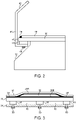
- a deflector 34 as shown in Figures 1 and 2 may be provided.
- the deflector 34 is preferably rigid and made of metal. As shown in Figure 1 , it may be preferable to provide deflectors 34 only along the long sides 36 of the transformer 10 and not on the short sides 38. The reason for this is that a rupture 32 of the weld 28 will only occur along the long sides 36 of the transformer 10 and will not occur along the short sides 38.
- the deflector 34 preferably extends along at least 50% of the length of the long sides 36, and more preferably, at least 75% of the length of the long sides 36.
- the deflector 34 may have a vertical portion 40 that is laterally spaced outward from the weld 28. Above the weld 28, the deflector 34 may also have an overhang portion 32 that extends inward toward the center of the tank 12 and covers the weld 28.
- spraying oil will contact the inner surface of the deflector 34 to redirect the escaping oil.
- outward spraying of oil is limited and prevented from spraying long distances away from the transformer 10.
- the deflector 34 may be attached to the flange 30 at the top of the tank 12.
- the deflector 34 may be attached to the bottom of the flange 30 as shown in Figure 2 .
- spaced apart blocks 44 are preferably welded to the bottom side of the flange 30.
- the deflector 34 may then be attached to the bottom side of the blocks 44.
- This arrangement is preferred to provide a pathway for oil to flow down after contacting the deflector 34. For example, after the oil contacts the inside of the deflector 34, oil can flow down through the lateral space 46 between the deflector 34 and the flange 30. The oil can then continue to flow through the vertical space 48 between the flange 30 and the deflector 34 and the blocks 44.
- the deflector 34 it is also preferred for the deflector 34 to be attached to the tank 12 (e.g., the flange 30) with threaded fasteners 50. This allows the deflectors 34 to be installed at a jobsite where the transformer 10 will be used instead of having to be installed at the factory. Thus, the transformer 10 can be shipped without the deflectors 34 being installed. This may be desirable to decrease shipping space needed to transport the transformer 10 to the location of use.
Landscapes
- Engineering & Computer Science (AREA)
- Power Engineering (AREA)
- Housings And Mounting Of Transformers (AREA)
- Transformer Cooling (AREA)
- Rectifiers (AREA)
- Driving Mechanisms And Operating Circuits Of Arc-Extinguishing High-Tension Switches (AREA)
Description
- The present inventions relate generally to a tank device adapted to accommodate an electrical equipment, and more particularly, to a deflector to redirect escaping oil.
- Large industrial electrical equipment, such as transformers and shunt reactors, typically have a tank as described in
US 2013/0187739 that encloses high-voltage components and cooling oil to cool the high-voltage components. In order to prevent people from inadvertently been exposed to the high-voltage components and cooling oil, the tank is sealed to prevent unintended access inside of the tank. - One risk associated with industrial electrical equipment are electrical faults that may occur within the equipment. When a fault occurs, an electrical arc may form between high-voltage components with different voltage potentials, between a high-voltage component and the tank wall (which is grounded), or elsewhere within the tank. As the arc forms, cooling oil around the arc vaporizes and increases the pressure within the equipment tank. If the pressure within the tank rises to a high enough level, the tank can explode by bursting the walls of the tank.
- One consequence of a tank explosion is that the cooling oil in the tank can escape. This can be problematic for many reasons. For example, the oil itself is considered to be a hazardous material. In some cases, the entire sidewall of a tank has been known to split from top to bottom which results in all of the cooling oil in the tank spilling out and contaminating the ground. However, even when the amount of escaping oil is minimized, the cooling oil may spray out of the tank and travel a significant distance before falling to the ground. In addition to the environmental concerns, spraying oil can be a safety hazard if nearby people are contacted by the spraying oil. For example, the high pressure or high temperature of an oil spray may harm a nearby person when an equipment tank explodes.
- The invention relates to a tank device adapted to accommodate an electrical equipment. The tank device is designed to rupture along the top of the tank to release pressure during an overpressure condition. When the tank ruptures, cooling oil inside of the tank can escape as a spray through the rupture opening. In order to prevent the spray from spreading out from the tank, a deflector is provided along the top of the tank to redirect escaping oil.
- The invention may be more fully understood by reading the following description in conjunction with the drawings, in which:
-
Figure 1 is a perspective view of a transformer; -
Figure 2 is a side view of a portion of the transformer; and -
Figure 3 is a side view of another portion of the transformer. - Referring now to the figures, and particularly
Figure 1 , anelectrical equipment 10 is shown, which in this embodiment is atransformer 10. Thetransformer 10 includes atank 12 withsidewalls 14 that extend upward from abase 16. The top of thetank 12 is enclosed with atop cover 18. As is understood in the art, thetransformer 10 includes high-voltage components and cooling oil in thetank 12. The high-voltage components are typically immersed in the cooling oil. Thetank 12 prevents inadvertent access to the high-voltage components therein and contains the cooling oil. In case oil leaks from thetank 12 or otherwise escapes therefrom, acontainment structure 20 may be provided around thebase 16 of thetransformer 10. Thecontainment structure 20 may be, for example, ashort wall 20 that surrounds thetransformer 10. However, it is understood that other types ofcontainment structures 20 may also be used, such as a drain that directs oil to an underground reservoir. Thus, thecontainment structure 20 traps oil that escapes to prevent oil from spilling out onto the surrounding ground. Preferably, thecontainment structure 20 is less than half the height of thesidewalls 14. - The
transformer 10 may be designed to respond in stages to overpressure conditions that may result from electrical arcs within thetransformer 10. For example, in a first stage, thesidewalls 14 of thetank 12 may be designed to plastically deform to absorb the overpressure condition without bursting thesidewalls 14. This may be done by addingreinforcement ribs 24 to thesidewalls 14 and widening thesidewall corners 26 to prevent thesidewalls 14 from bursting open. - As shown in
Figure 3 , a second stage may include a weakenedregion 28 that ruptures to allow pressure to escape from thetank 12. Preferably, thetank 12 plastically deforms first as noted above in case plastic deformation is sufficient to contain the overpressure condition without rupturing thetank 12. However, if the overpressure condition is high enough, thetank 12 may be designed to rupture in a controlled fashion to minimize any damage or harm that may be caused by thetransformer 10 failure. - As shown in
Figures 2 and 3 , thetop cover 18 is preferably welded 28 around its perimeter to aflange 30 at the top of thesidewalls 14. However, it may also be possible to attach thetop cover 18 to theflange 30 with bolts. Theweld 28 may be designed as a weakenedregion 28 that ruptures at a particular pressure level. Thus, as shown inFigure 3 , when the weakenedregion 28 ruptures, theweld 28 separates 28A, 28B and thetop cover 18 separates from theflange 30 to form anopening 32 therebetween. As a result, pressure can be released from thetank 12 through the rupturedopening 32. Preferably, the weakenedregion 28 is along the top portion of thetransformer 10 so that most of the cooling oil remains in thetank 12 after the rupture without spilling on the ground. - Although the
rupture 32 is designed to occur at the top of thetank 12, there remains some concern that a certain amount of oil may spray out of the rupturedopening 32 during an overpressure condition. In order to minimize any environmental or safety hazards associated with spraying oil, adeflector 34 as shown inFigures 1 and2 may be provided. Thedeflector 34 is preferably rigid and made of metal. As shown inFigure 1 , it may be preferable to providedeflectors 34 only along thelong sides 36 of thetransformer 10 and not on theshort sides 38.
The reason for this is that arupture 32 of theweld 28 will only occur along thelong sides 36 of thetransformer 10 and will not occur along theshort sides 38. Moreover, it may be useful to leave the top of theshort sides 38 open and unobstructed by adeflector 34 to allow easier access for piping and other equipment. In order to completely cover the rupturedopening 32, thedeflector 34 preferably extends along at least 50% of the length of thelong sides 36, and more preferably, at least 75% of the length of thelong sides 36. - As shown in
Figure 2 , thedeflector 34 may have avertical portion 40 that is laterally spaced outward from theweld 28. Above theweld 28, thedeflector 34 may also have anoverhang portion 32 that extends inward toward the center of thetank 12 and covers theweld 28. Thus, when oil escapes from a rupturedopening 32 through theweld 28, spraying oil will contact the inner surface of thedeflector 34 to redirect the escaping oil. As a result, outward spraying of oil is limited and prevented from spraying long distances away from thetransformer 10. - The
deflector 34 may be attached to theflange 30 at the top of thetank 12. For example, thedeflector 34 may be attached to the bottom of theflange 30 as shown inFigure 2 . As shown inFigure 3 , spaced apartblocks 44 are preferably welded to the bottom side of theflange 30. Thedeflector 34 may then be attached to the bottom side of theblocks 44. This arrangement is preferred to provide a pathway for oil to flow down after contacting thedeflector 34. For example, after the oil contacts the inside of thedeflector 34, oil can flow down through thelateral space 46 between thedeflector 34 and theflange 30. The oil can then continue to flow through thevertical space 48 between theflange 30 and thedeflector 34 and theblocks 44. In order to see thevertical space 48 more clearly, the vertical andoverhang portions deflector 34 have been cut away inFigure 3 . The oil then flows downward along the outside of thesidewalls 14 of thetank 12. As a result, oil flows down along thesidewalls 14 to thecontainment structure 20 without escaping uncontrolled away from thecontainment structure 20. - As shown in
Figure 3 , it is also preferred for thedeflector 34 to be attached to the tank 12 (e.g., the flange 30) with threadedfasteners 50. This allows thedeflectors 34 to be installed at a jobsite where thetransformer 10 will be used instead of having to be installed at the factory. Thus, thetransformer 10 can be shipped without thedeflectors 34 being installed. This may be desirable to decrease shipping space needed to transport thetransformer 10 to the location of use. - While preferred embodiments of the inventions have been described, it should be understood that the inventions are not so limited, and modifications may be made without departing from the scope of the appended claims. While each embodiment described herein may refer only to certain features and may not specifically refer to every feature described with respect to other embodiments, it should be recognized that the features described herein are interchangeable unless described otherwise, even where no reference is made to a specific feature. It should also be understood that the advantages described above are not necessarily the only advantages of the inventions, and it is not necessarily expected that all of the described advantages will be achieved with every embodiment of the inventions. The scope of the invention is defined by the appended claims, and all devices and methods that come within the scope of the claims are intended to be embraced therein.
Claims (18)
- Tank device adapted to accommodate an electrical equipment, comprising:a tank (12) containing a cooling oil, the tank (12) has sidewalls (14) and a flange (30) at a top of the tank (12);a top cover attached to the flange (30);a weakened region (28) between the top cover (18) and the flange (30), wherein the weakened region (28) ruptures when an overpressure condition occurs in the tank (12) to release pressure;a deflector (34) extending along at least a portion of the top cover (18) anddisposed outward from the weakened region (28), wherein at least some of the cooling oil escapes under pressure when the weakened region (28) ruptures, the escaped cooling oil contacting an inner surface of the deflector and being redirected to limit outward spraying of the cooling oil.
- Tank device according to claim 1, wherein the top cover (18) is welded to the flange (30) of the tank (12).
- Tank device according to claim 1, wherein the deflector (34) is attached to the flange (30).
- Tank device according to claim 3, wherein the deflector (34) is attached to the flange (30) with threaded fasteners (50), the deflector (34) thereby being configured to be unattached from the tank (12) during shipping and to be attached to the tank (12) at a site of usage.
- Tank device according to claim 1, further comprising a vertical space (48) below the weakened region (28) and between the deflector (34) and the tank (12), the vertical space (48) being configured for the cooling oil to flow down through the space to the sidewalls (14) of the tank (12).
- Tank device according to claim 5, further comprising spaced apart blocks (44) attached to the tank (12), the deflector (34) being attached to the blocks (44), wherein the space (48) is disposed between the spaced apart blocks (44) and between the tank (12) and the deflector (34).
- Tank device according to claim 6, wherein the tank (12) comprises a flange (30) at a top thereof, the blocks (44) are attached to a bottom side of the flange (30), and the defector is attached to a bottom side of the blocks (44).
- Tank device according to claim 1, further comprising a containment structure (20) surrounding a base of the tank (12), the containment structure (20) being configured to contain cooling oil that escapes from the tank (12), wherein the deflector (34) redirects the escaped cooling oil to an inside of the containment structure (20).
- Tank device according to claim 1, wherein the deflector (34) comprises a vertical portion (40) laterally spaced from the weakened region (28).
- Tank device according to claim 1, wherein the deflector (34) comprises an overhang portion (32) disposed over the weakened region (28) and extending inward toward a center of the tank (12).
- Tank device according to claim 1, wherein the sidewalls (14) comprise opposing short side walls (14) and opposing long side walls (14), a part of the deflector (34) being disposed along each of the opposing long side walls and not along the opposing short side walls (14).
- Tank device according to claim 1, wherein deflector (34) extends along at least 50% of a length of one of the sidewalls (14).
- Tank device according to claim 12, wherein deflector (34) extends along at least 75% of a length of one of the sidewalls (14).
- Tank device according to claim 1, wherein the side walls (14) plastically deform to absorb overpressure before the weakened region (28) ruptures.
- Tank device according to claim 1, further comprising a vertical space (48) below the weakened region (28) and between the deflector (34) and the tank (12), the vertical space (48) being configured for the cooling oil to flow down through the space to the sidewalls (14) of the tank (12), and further comprising a containment structure (20) surrounding a base of the tank (12), the containment structure (20) being configured to contain cooling oil that escapes from the tank (12), wherein the deflector (34) redirects the escaped cooling oil to an inside of the containment structure (20).
- Tank device according to claim 15, wherein the top cover (18) is welded to the flange (30) of the tank (12), the deflector (34) is attached to the tank (12) with threaded fasteners, the deflector (34) thereby being configured to be unattached from the tank (12) during shipping and to be attached to the tank (12) at a site of usage, the deflector (34) comprises a vertical portion (40) laterally spaced from the weakened region (28), and the deflector (34) comprises an overhang portion (32) disposed over the weakened region (28) and extending inward toward a center of the tank (12).
- Tank device according to claim 16, wherein the tank (12) comprises a flange (30) at a top thereof, the top cover (18) being welded to the flange (30), the deflector (34) is attached to the flange (30), the side walls (14) comprise opposing short side walls (14) and opposing long side walls (14), one of the deflector (34) being disposed along each of the opposing long side walls (14) and not along the opposing short side walls (14), and the deflector (34) extends along at least 75% of a length of one of the sidewalls (14).
- Tank device according to claim 17, further comprising spaced apart blocks (44) attached to a bottom side of the flange (30), the deflector (34) is attached to a bottom side of the blocks (44), the space is disposed between the blocks (44) and between the tank (12) and the deflector (34), and the side walls (14) plastically deform to absorb overpressure before the weakened region (28) ruptures.
Applications Claiming Priority (2)
| Application Number | Priority Date | Filing Date | Title |
|---|---|---|---|
| US15/987,315 US10854368B2 (en) | 2018-05-23 | 2018-05-23 | Electrical equipment with rupture oil deflector |
| PCT/IB2019/054245 WO2019224747A2 (en) | 2018-05-23 | 2019-05-22 | Electrical equipment with rupture oil deflector |
Publications (2)
| Publication Number | Publication Date |
|---|---|
| EP3797433A2 EP3797433A2 (en) | 2021-03-31 |
| EP3797433B1 true EP3797433B1 (en) | 2022-07-06 |
Family
ID=68613486
Family Applications (1)
| Application Number | Title | Priority Date | Filing Date |
|---|---|---|---|
| EP19737880.5A Active EP3797433B1 (en) | 2018-05-23 | 2019-05-22 | Electrical equipment with rupture oil deflector |
Country Status (7)
| Country | Link |
|---|---|
| US (1) | US10854368B2 (en) |
| EP (1) | EP3797433B1 (en) |
| JP (1) | JP7018524B2 (en) |
| KR (1) | KR102397157B1 (en) |
| CN (1) | CN110534304B (en) |
| CA (1) | CA3023909C (en) |
| WO (1) | WO2019224747A2 (en) |
Families Citing this family (2)
| Publication number | Priority date | Publication date | Assignee | Title |
|---|---|---|---|---|
| CN115207823B (en) * | 2022-05-25 | 2025-05-30 | 安徽明远电力设备制造有限公司 | A buried box transformer with waterproof and corrosion-resistant functions |
| CN120473295B (en) * | 2025-04-24 | 2026-04-07 | 镇江同美建设工程有限公司 | Three-phase differential mode magnetic integrated inductor |
Family Cites Families (36)
| Publication number | Priority date | Publication date | Assignee | Title |
|---|---|---|---|---|
| US3474369A (en) * | 1967-12-05 | 1969-10-21 | Allis Chalmers Mfg Co | Hermetically sealed distribution transformer |
| US3914528A (en) | 1974-03-20 | 1975-10-21 | Qualitrol Corp | Pressure relief device for power transformer |
| US4005341A (en) * | 1975-12-17 | 1977-01-25 | R. E. Uptegraff Manufacturing Company | Casing construction for pole type dielectric containing transformer |
| US4106068A (en) * | 1977-01-27 | 1978-08-08 | General Electric Company | Pressure sensitive interrupter |
| US4085395A (en) * | 1977-02-03 | 1978-04-18 | Communications Satellite Corporation | High voltage transformer package |
| US4173776A (en) * | 1977-09-08 | 1979-11-06 | Westinghouse Electric Corp. | Power capacitor with an internal support structure |
| JPS5818264Y2 (en) * | 1978-04-07 | 1983-04-13 | 株式会社高岳製作所 | Pressure relief device for oil-filled appliances |
| DE2912460C2 (en) * | 1979-03-29 | 1984-04-05 | Erhard 6000 Frankfurt Crema | Device for separating oil from an oil-water mixture |
| US4453197A (en) | 1981-10-22 | 1984-06-05 | Mcgraw-Edison Company | Dielectric fluid tank |
| CH664040A5 (en) * | 1982-07-19 | 1988-01-29 | Bbc Brown Boveri & Cie | PRESSURE GAS-INSULATED CURRENT TRANSFORMER. |
| JPS62229911A (en) * | 1986-03-31 | 1987-10-08 | Toshiba Corp | Oil-filled transformer |
| CA2055109A1 (en) | 1991-11-07 | 1993-05-08 | Eugene Y. G. Yao | Explosion resistant, oil insulated, current transformer |
| JPH07220934A (en) * | 1994-02-03 | 1995-08-18 | Mitsubishi Electric Corp | Pressure relief device |
| FR2791463B1 (en) * | 1999-03-22 | 2001-06-29 | Philippe Magnier | DEVICE FOR PREVENTION AGAINST EXPLOSION OF ELECTRICAL TRANSFORMERS |
| FR2888034B1 (en) | 2005-06-29 | 2010-10-08 | Philippe Magnier | DEVICE FOR PREVENTING THE EXPLOSION OF AN ELECTRICAL TRANSFORMER |
| WO2007057917A1 (en) * | 2005-11-16 | 2007-05-24 | Ctr Manufacturing Industries Limited | Transformer conservator isolation valve (tciv) |
| MEP13109A (en) | 2006-10-27 | 2011-12-20 | Device for prevention against the explosion of an electric transformer member | |
| US8710946B2 (en) * | 2008-09-17 | 2014-04-29 | General Electric Company | Rupture resistant system |
| US8717134B2 (en) * | 2008-09-17 | 2014-05-06 | General Electric Company | System with directional pressure venting |
| CN102171778B (en) | 2008-10-06 | 2013-07-03 | Abb技术有限公司 | A transformer assembly |
| US8284006B2 (en) * | 2010-04-14 | 2012-10-09 | Southern Transformers & Magnetics, Llc | Passive air cooling of a dry-type electrical transformer |
| CN102651267A (en) * | 2011-02-25 | 2012-08-29 | 上海休伯康特能源设备有限公司 | Oil explosion-proof and leak-proof amorphous alloy transformer |
| US8319590B2 (en) | 2011-03-21 | 2012-11-27 | Philippe Magnier Llc | Device for explosion prevention of an on load tap changer including a rupture element |
| EP2571034A1 (en) * | 2011-09-19 | 2013-03-20 | Siemens Aktiengesellschaft | Subsea transformer enclosure |
| US8779880B2 (en) | 2012-01-23 | 2014-07-15 | Abb Technology Ag | Fluid deflection transformer tank |
| US9066420B2 (en) | 2012-03-16 | 2015-06-23 | Hamilton Sundstrand Corporation | Explosion proof by containment enclosure for housing electrical equipment |
| EP2744061A1 (en) | 2012-12-12 | 2014-06-18 | ABB Technology AG | Transformer protection system |
| US20140166329A1 (en) * | 2012-12-17 | 2014-06-19 | Abb Technology Ag | Dry-Type Transformer Arc Resistant Enclosure Having Pressure Relief Structure |
| DE102013107559A1 (en) * | 2013-07-16 | 2015-01-22 | Maschinenfabrik Reinhausen Gmbh | Bursting device for a high voltage device |
| CN203950641U (en) * | 2014-07-03 | 2014-11-19 | 青岛海电电气有限公司 | There is the oil tank of transformer of oil-cutting device |
| CN204045349U (en) * | 2014-09-19 | 2014-12-24 | 浙江金盘变压器有限公司 | Three low pressure oil-filled transformers |
| US9815594B2 (en) | 2014-10-15 | 2017-11-14 | Abb Schweiz Ag | Tank for electrical equipment |
| WO2016147158A1 (en) | 2015-03-18 | 2016-09-22 | Efacec Energia - Máquinas E Equipamentos Eléctricos S.A. | Oil immersed power transformer tank wall |
| CN106683826B (en) * | 2017-02-22 | 2018-08-17 | 江苏宝亨新电气有限公司 | A kind of oil-immersed transformer of high security |
| US11439038B2 (en) * | 2017-07-28 | 2022-09-06 | Hammond Power Solutions, Inc. | Outdoor ventilated enclosure |
| CN107452478B (en) * | 2017-09-27 | 2023-05-23 | 洛阳市星合特种变压器有限公司 | Transformer convenient to overhaul |
-
2018
- 2018-05-23 US US15/987,315 patent/US10854368B2/en active Active
- 2018-11-12 CN CN201811340687.8A patent/CN110534304B/en active Active
- 2018-11-13 CA CA3023909A patent/CA3023909C/en active Active
-
2019
- 2019-05-22 EP EP19737880.5A patent/EP3797433B1/en active Active
- 2019-05-22 KR KR1020207029844A patent/KR102397157B1/en active Active
- 2019-05-22 JP JP2020563975A patent/JP7018524B2/en active Active
- 2019-05-22 WO PCT/IB2019/054245 patent/WO2019224747A2/en not_active Ceased
Also Published As
| Publication number | Publication date |
|---|---|
| JP7018524B2 (en) | 2022-02-10 |
| CN110534304B (en) | 2022-03-25 |
| KR102397157B1 (en) | 2022-05-12 |
| US10854368B2 (en) | 2020-12-01 |
| US20190362876A1 (en) | 2019-11-28 |
| CN110534304A (en) | 2019-12-03 |
| WO2019224747A2 (en) | 2019-11-28 |
| KR20200135816A (en) | 2020-12-03 |
| CA3023909C (en) | 2020-12-01 |
| WO2019224747A3 (en) | 2020-01-09 |
| JP2021524156A (en) | 2021-09-09 |
| CA3023909A1 (en) | 2019-11-23 |
| EP3797433A2 (en) | 2021-03-31 |
Similar Documents
| Publication | Publication Date | Title |
|---|---|---|
| KR101325252B1 (en) | Device for preventing the explosion of an electrical transformer | |
| CA3023909C (en) | Electrical equipment with rupture oil deflector | |
| BG64202B1 (en) | Device for preventing explosions in electrical transformers | |
| US4005341A (en) | Casing construction for pole type dielectric containing transformer | |
| US7902950B2 (en) | System for preventing rupture of transformer tank | |
| US20120200961A1 (en) | Electric transformer explosion prevention device provided with a liquid detector | |
| KR101047172B1 (en) | Explosion-proof device for insulating oil tank of transformer | |
| US3339791A (en) | Emergency venting manhole cover | |
| KR20230048141A (en) | Housing part, electrical system and method of operation | |
| KR200296641Y1 (en) | Low loss type pad mounted transformers | |
| US3179285A (en) | Manhole fusible joint and improved gasket | |
| KR100887719B1 (en) | Top cover with eco-friendly leakproof cover for transformer safety release and replacement of top cover with leak-proof cover | |
| US12259050B1 (en) | Technologies for preventing the explosion of electrical transformers | |
| KR102755767B1 (en) | Arc gas exhaust apparatus for air circuit breaker | |
| JPS6276705A (en) | Oil-filled electric device | |
| JP2013243325A (en) | Cable replay device | |
| US4173776A (en) | Power capacitor with an internal support structure | |
| US20070295692A1 (en) | Fault tolerant high voltage switching elements and electrical components | |
| EP3764377A1 (en) | Tank for a liquid-filled shell transformer or shell reactor | |
| CN120497577A (en) | Protection device and energy storage device | |
| KR0118890Y1 (en) | Handhole Cover for Transformer | |
| AU2003200081B1 (en) | Containment of high voltage power transformer internal explosions | |
| HK1116294B (en) | Device for preventing the explosion of an electrical transformer | |
| HK1228556B (en) | Burst arrangement for a high voltage device |
Legal Events
| Date | Code | Title | Description |
|---|---|---|---|
| STAA | Information on the status of an ep patent application or granted ep patent |
Free format text: STATUS: UNKNOWN |
|
| STAA | Information on the status of an ep patent application or granted ep patent |
Free format text: STATUS: THE INTERNATIONAL PUBLICATION HAS BEEN MADE |
|
| PUAI | Public reference made under article 153(3) epc to a published international application that has entered the european phase |
Free format text: ORIGINAL CODE: 0009012 |
|
| STAA | Information on the status of an ep patent application or granted ep patent |
Free format text: STATUS: REQUEST FOR EXAMINATION WAS MADE |
|
| 17P | Request for examination filed |
Effective date: 20200909 |
|
| AK | Designated contracting states |
Kind code of ref document: A2 Designated state(s): AL AT BE BG CH CY CZ DE DK EE ES FI FR GB GR HR HU IE IS IT LI LT LU LV MC MK MT NL NO PL PT RO RS SE SI SK SM TR |
|
| AX | Request for extension of the european patent |
Extension state: BA ME |
|
| DAV | Request for validation of the european patent (deleted) | ||
| DAX | Request for extension of the european patent (deleted) | ||
| RAP3 | Party data changed (applicant data changed or rights of an application transferred) |
Owner name: HITACHI ENERGY SWITZERLAND AG |
|
| GRAP | Despatch of communication of intention to grant a patent |
Free format text: ORIGINAL CODE: EPIDOSNIGR1 |
|
| STAA | Information on the status of an ep patent application or granted ep patent |
Free format text: STATUS: GRANT OF PATENT IS INTENDED |
|
| INTG | Intention to grant announced |
Effective date: 20220121 |
|
| RIN1 | Information on inventor provided before grant (corrected) |
Inventor name: LAMBERT, CLAUDE Inventor name: COTE, ALEXANDRE Inventor name: LAMOTHE, PATRICE Inventor name: BRODEUR, SAMUEL |
|
| GRAS | Grant fee paid |
Free format text: ORIGINAL CODE: EPIDOSNIGR3 |
|
| GRAA | (expected) grant |
Free format text: ORIGINAL CODE: 0009210 |
|
| STAA | Information on the status of an ep patent application or granted ep patent |
Free format text: STATUS: THE PATENT HAS BEEN GRANTED |
|
| AK | Designated contracting states |
Kind code of ref document: B1 Designated state(s): AL AT BE BG CH CY CZ DE DK EE ES FI FR GB GR HR HU IE IS IT LI LT LU LV MC MK MT NL NO PL PT RO RS SE SI SK SM TR |
|
| REG | Reference to a national code |
Ref country code: AT Ref legal event code: REF Ref document number: 1503455 Country of ref document: AT Kind code of ref document: T Effective date: 20220715 Ref country code: CH Ref legal event code: EP |
|
| REG | Reference to a national code |
Ref country code: DE Ref legal event code: R096 Ref document number: 602019016764 Country of ref document: DE |
|
| REG | Reference to a national code |
Ref country code: IE Ref legal event code: FG4D |
|
| REG | Reference to a national code |
Ref country code: NL Ref legal event code: FP |
|
| REG | Reference to a national code |
Ref country code: LT Ref legal event code: MG9D |
|
| PG25 | Lapsed in a contracting state [announced via postgrant information from national office to epo] |
Ref country code: SE Free format text: LAPSE BECAUSE OF FAILURE TO SUBMIT A TRANSLATION OF THE DESCRIPTION OR TO PAY THE FEE WITHIN THE PRESCRIBED TIME-LIMIT Effective date: 20220706 Ref country code: RS Free format text: LAPSE BECAUSE OF FAILURE TO SUBMIT A TRANSLATION OF THE DESCRIPTION OR TO PAY THE FEE WITHIN THE PRESCRIBED TIME-LIMIT Effective date: 20220706 Ref country code: PT Free format text: LAPSE BECAUSE OF FAILURE TO SUBMIT A TRANSLATION OF THE DESCRIPTION OR TO PAY THE FEE WITHIN THE PRESCRIBED TIME-LIMIT Effective date: 20221107 Ref country code: NO Free format text: LAPSE BECAUSE OF FAILURE TO SUBMIT A TRANSLATION OF THE DESCRIPTION OR TO PAY THE FEE WITHIN THE PRESCRIBED TIME-LIMIT Effective date: 20221006 Ref country code: LV Free format text: LAPSE BECAUSE OF FAILURE TO SUBMIT A TRANSLATION OF THE DESCRIPTION OR TO PAY THE FEE WITHIN THE PRESCRIBED TIME-LIMIT Effective date: 20220706 Ref country code: LT Free format text: LAPSE BECAUSE OF FAILURE TO SUBMIT A TRANSLATION OF THE DESCRIPTION OR TO PAY THE FEE WITHIN THE PRESCRIBED TIME-LIMIT Effective date: 20220706 Ref country code: FI Free format text: LAPSE BECAUSE OF FAILURE TO SUBMIT A TRANSLATION OF THE DESCRIPTION OR TO PAY THE FEE WITHIN THE PRESCRIBED TIME-LIMIT Effective date: 20220706 Ref country code: ES Free format text: LAPSE BECAUSE OF FAILURE TO SUBMIT A TRANSLATION OF THE DESCRIPTION OR TO PAY THE FEE WITHIN THE PRESCRIBED TIME-LIMIT Effective date: 20220706 |
|
| REG | Reference to a national code |
Ref country code: AT Ref legal event code: MK05 Ref document number: 1503455 Country of ref document: AT Kind code of ref document: T Effective date: 20220706 |
|
| PG25 | Lapsed in a contracting state [announced via postgrant information from national office to epo] |
Ref country code: PL Free format text: LAPSE BECAUSE OF FAILURE TO SUBMIT A TRANSLATION OF THE DESCRIPTION OR TO PAY THE FEE WITHIN THE PRESCRIBED TIME-LIMIT Effective date: 20220706 Ref country code: IS Free format text: LAPSE BECAUSE OF FAILURE TO SUBMIT A TRANSLATION OF THE DESCRIPTION OR TO PAY THE FEE WITHIN THE PRESCRIBED TIME-LIMIT Effective date: 20221106 Ref country code: GR Free format text: LAPSE BECAUSE OF FAILURE TO SUBMIT A TRANSLATION OF THE DESCRIPTION OR TO PAY THE FEE WITHIN THE PRESCRIBED TIME-LIMIT Effective date: 20221007 |
|
| REG | Reference to a national code |
Ref country code: DE Ref legal event code: R097 Ref document number: 602019016764 Country of ref document: DE |
|
| PG25 | Lapsed in a contracting state [announced via postgrant information from national office to epo] |
Ref country code: SM Free format text: LAPSE BECAUSE OF FAILURE TO SUBMIT A TRANSLATION OF THE DESCRIPTION OR TO PAY THE FEE WITHIN THE PRESCRIBED TIME-LIMIT Effective date: 20220706 Ref country code: RO Free format text: LAPSE BECAUSE OF FAILURE TO SUBMIT A TRANSLATION OF THE DESCRIPTION OR TO PAY THE FEE WITHIN THE PRESCRIBED TIME-LIMIT Effective date: 20220706 Ref country code: DK Free format text: LAPSE BECAUSE OF FAILURE TO SUBMIT A TRANSLATION OF THE DESCRIPTION OR TO PAY THE FEE WITHIN THE PRESCRIBED TIME-LIMIT Effective date: 20220706 Ref country code: CZ Free format text: LAPSE BECAUSE OF FAILURE TO SUBMIT A TRANSLATION OF THE DESCRIPTION OR TO PAY THE FEE WITHIN THE PRESCRIBED TIME-LIMIT Effective date: 20220706 Ref country code: AT Free format text: LAPSE BECAUSE OF FAILURE TO SUBMIT A TRANSLATION OF THE DESCRIPTION OR TO PAY THE FEE WITHIN THE PRESCRIBED TIME-LIMIT Effective date: 20220706 |
|
| PLBE | No opposition filed within time limit |
Free format text: ORIGINAL CODE: 0009261 |
|
| STAA | Information on the status of an ep patent application or granted ep patent |
Free format text: STATUS: NO OPPOSITION FILED WITHIN TIME LIMIT |
|
| PG25 | Lapsed in a contracting state [announced via postgrant information from national office to epo] |
Ref country code: SK Free format text: LAPSE BECAUSE OF FAILURE TO SUBMIT A TRANSLATION OF THE DESCRIPTION OR TO PAY THE FEE WITHIN THE PRESCRIBED TIME-LIMIT Effective date: 20220706 Ref country code: EE Free format text: LAPSE BECAUSE OF FAILURE TO SUBMIT A TRANSLATION OF THE DESCRIPTION OR TO PAY THE FEE WITHIN THE PRESCRIBED TIME-LIMIT Effective date: 20220706 |
|
| 26N | No opposition filed |
Effective date: 20230411 |
|
| PG25 | Lapsed in a contracting state [announced via postgrant information from national office to epo] |
Ref country code: AL Free format text: LAPSE BECAUSE OF FAILURE TO SUBMIT A TRANSLATION OF THE DESCRIPTION OR TO PAY THE FEE WITHIN THE PRESCRIBED TIME-LIMIT Effective date: 20220706 |
|
| P01 | Opt-out of the competence of the unified patent court (upc) registered |
Effective date: 20230527 |
|
| PG25 | Lapsed in a contracting state [announced via postgrant information from national office to epo] |
Ref country code: SI Free format text: LAPSE BECAUSE OF FAILURE TO SUBMIT A TRANSLATION OF THE DESCRIPTION OR TO PAY THE FEE WITHIN THE PRESCRIBED TIME-LIMIT Effective date: 20220706 |
|
| REG | Reference to a national code |
Ref country code: CH Ref legal event code: PL |
|
| PG25 | Lapsed in a contracting state [announced via postgrant information from national office to epo] |
Ref country code: MC Free format text: LAPSE BECAUSE OF FAILURE TO SUBMIT A TRANSLATION OF THE DESCRIPTION OR TO PAY THE FEE WITHIN THE PRESCRIBED TIME-LIMIT Effective date: 20220706 |
|
| REG | Reference to a national code |
Ref country code: BE Ref legal event code: MM Effective date: 20230531 |
|
| PG25 | Lapsed in a contracting state [announced via postgrant information from national office to epo] |
Ref country code: MC Free format text: LAPSE BECAUSE OF FAILURE TO SUBMIT A TRANSLATION OF THE DESCRIPTION OR TO PAY THE FEE WITHIN THE PRESCRIBED TIME-LIMIT Effective date: 20220706 Ref country code: LU Free format text: LAPSE BECAUSE OF NON-PAYMENT OF DUE FEES Effective date: 20230522 Ref country code: LI Free format text: LAPSE BECAUSE OF NON-PAYMENT OF DUE FEES Effective date: 20230531 Ref country code: IT Free format text: LAPSE BECAUSE OF FAILURE TO SUBMIT A TRANSLATION OF THE DESCRIPTION OR TO PAY THE FEE WITHIN THE PRESCRIBED TIME-LIMIT Effective date: 20220706 Ref country code: CH Free format text: LAPSE BECAUSE OF NON-PAYMENT OF DUE FEES Effective date: 20230531 |
|
| REG | Reference to a national code |
Ref country code: IE Ref legal event code: MM4A |
|
| REG | Reference to a national code |
Ref country code: DE Ref legal event code: R081 Ref document number: 602019016764 Country of ref document: DE Owner name: HITACHI ENERGY LTD, CH Free format text: FORMER OWNER: HITACHI ENERGY SWITZERLAND AG, BADEN, CH |
|
| REG | Reference to a national code |
Ref country code: NL Ref legal event code: PD Owner name: HITACHI ENERGY LTD; CH Free format text: DETAILS ASSIGNMENT: CHANGE OF OWNER(S), MERGE; FORMER OWNER NAME: HITACHI ENERGY SWITZERLAND AG Effective date: 20240403 |
|
| PG25 | Lapsed in a contracting state [announced via postgrant information from national office to epo] |
Ref country code: IE Free format text: LAPSE BECAUSE OF NON-PAYMENT OF DUE FEES Effective date: 20230522 |
|
| PG25 | Lapsed in a contracting state [announced via postgrant information from national office to epo] |
Ref country code: IE Free format text: LAPSE BECAUSE OF NON-PAYMENT OF DUE FEES Effective date: 20230522 |
|
| PG25 | Lapsed in a contracting state [announced via postgrant information from national office to epo] |
Ref country code: BE Free format text: LAPSE BECAUSE OF NON-PAYMENT OF DUE FEES Effective date: 20230531 |
|
| PG25 | Lapsed in a contracting state [announced via postgrant information from national office to epo] |
Ref country code: HR Free format text: LAPSE BECAUSE OF FAILURE TO SUBMIT A TRANSLATION OF THE DESCRIPTION OR TO PAY THE FEE WITHIN THE PRESCRIBED TIME-LIMIT Effective date: 20220706 |
|
| REG | Reference to a national code |
Ref country code: GB Ref legal event code: 732E Free format text: REGISTERED BETWEEN 20240718 AND 20240724 |
|
| PG25 | Lapsed in a contracting state [announced via postgrant information from national office to epo] |
Ref country code: HR Free format text: LAPSE BECAUSE OF FAILURE TO SUBMIT A TRANSLATION OF THE DESCRIPTION OR TO PAY THE FEE WITHIN THE PRESCRIBED TIME-LIMIT Effective date: 20220706 |
|
| PG25 | Lapsed in a contracting state [announced via postgrant information from national office to epo] |
Ref country code: BG Free format text: LAPSE BECAUSE OF FAILURE TO SUBMIT A TRANSLATION OF THE DESCRIPTION OR TO PAY THE FEE WITHIN THE PRESCRIBED TIME-LIMIT Effective date: 20220706 |
|
| PG25 | Lapsed in a contracting state [announced via postgrant information from national office to epo] |
Ref country code: BG Free format text: LAPSE BECAUSE OF FAILURE TO SUBMIT A TRANSLATION OF THE DESCRIPTION OR TO PAY THE FEE WITHIN THE PRESCRIBED TIME-LIMIT Effective date: 20220706 |
|
| REG | Reference to a national code |
Ref country code: DE Ref legal event code: R082 Ref document number: 602019016764 Country of ref document: DE Representative=s name: DENNEMEYER & ASSOCIATES RECHTSANWALTSGESELLSCH, DE |
|
| PG25 | Lapsed in a contracting state [announced via postgrant information from national office to epo] |
Ref country code: CY Free format text: LAPSE BECAUSE OF FAILURE TO SUBMIT A TRANSLATION OF THE DESCRIPTION OR TO PAY THE FEE WITHIN THE PRESCRIBED TIME-LIMIT; INVALID AB INITIO Effective date: 20190522 |
|
| PG25 | Lapsed in a contracting state [announced via postgrant information from national office to epo] |
Ref country code: HU Free format text: LAPSE BECAUSE OF FAILURE TO SUBMIT A TRANSLATION OF THE DESCRIPTION OR TO PAY THE FEE WITHIN THE PRESCRIBED TIME-LIMIT; INVALID AB INITIO Effective date: 20190522 |
|
| PG25 | Lapsed in a contracting state [announced via postgrant information from national office to epo] |
Ref country code: TR Free format text: LAPSE BECAUSE OF FAILURE TO SUBMIT A TRANSLATION OF THE DESCRIPTION OR TO PAY THE FEE WITHIN THE PRESCRIBED TIME-LIMIT Effective date: 20220706 |
|
| PGFP | Annual fee paid to national office [announced via postgrant information from national office to epo] |
Ref country code: NL Payment date: 20260520 Year of fee payment: 8 |
|
| PGFP | Annual fee paid to national office [announced via postgrant information from national office to epo] |
Ref country code: GB Payment date: 20260522 Year of fee payment: 8 |
|
| PGFP | Annual fee paid to national office [announced via postgrant information from national office to epo] |
Ref country code: DE Payment date: 20260522 Year of fee payment: 8 |
|
| PG25 | Lapsed in a contracting state [announced via postgrant information from national office to epo] |
Ref country code: MT Free format text: LAPSE BECAUSE OF NON-PAYMENT OF DUE FEES Effective date: 20230522 |
|
| PGFP | Annual fee paid to national office [announced via postgrant information from national office to epo] |
Ref country code: FR Payment date: 20260526 Year of fee payment: 8 |