EP3797211B1 - Turbine exhaust crack mitigation using partial collars - Google Patents
Turbine exhaust crack mitigation using partial collars Download PDFInfo
- Publication number
- EP3797211B1 EP3797211B1 EP19733323.0A EP19733323A EP3797211B1 EP 3797211 B1 EP3797211 B1 EP 3797211B1 EP 19733323 A EP19733323 A EP 19733323A EP 3797211 B1 EP3797211 B1 EP 3797211B1
- Authority
- EP
- European Patent Office
- Prior art keywords
- duct
- collar
- wall
- strut shield
- interface
- Prior art date
- Legal status (The legal status is an assumption and is not a legal conclusion. Google has not performed a legal analysis and makes no representation as to the accuracy of the status listed.)
- Active
Links
Images



Classifications
-
- F—MECHANICAL ENGINEERING; LIGHTING; HEATING; WEAPONS; BLASTING
- F01—MACHINES OR ENGINES IN GENERAL; ENGINE PLANTS IN GENERAL; STEAM ENGINES
- F01D—NON-POSITIVE DISPLACEMENT MACHINES OR ENGINES, e.g. STEAM TURBINES
- F01D9/00—Stators
- F01D9/02—Nozzles; Nozzle boxes; Stator blades; Guide conduits, e.g. individual nozzles
- F01D9/04—Nozzles; Nozzle boxes; Stator blades; Guide conduits, e.g. individual nozzles forming ring or sector
-
- F—MECHANICAL ENGINEERING; LIGHTING; HEATING; WEAPONS; BLASTING
- F01—MACHINES OR ENGINES IN GENERAL; ENGINE PLANTS IN GENERAL; STEAM ENGINES
- F01D—NON-POSITIVE DISPLACEMENT MACHINES OR ENGINES, e.g. STEAM TURBINES
- F01D9/00—Stators
- F01D9/06—Fluid supply conduits to nozzles or the like
- F01D9/065—Fluid supply or removal conduits traversing the working fluid flow, e.g. for lubrication-, cooling-, or sealing fluids
-
- F—MECHANICAL ENGINEERING; LIGHTING; HEATING; WEAPONS; BLASTING
- F01—MACHINES OR ENGINES IN GENERAL; ENGINE PLANTS IN GENERAL; STEAM ENGINES
- F01D—NON-POSITIVE DISPLACEMENT MACHINES OR ENGINES, e.g. STEAM TURBINES
- F01D25/00—Component parts, details, or accessories, not provided for in, or of interest apart from, other groups
- F01D25/24—Casings; Casing parts, e.g. diaphragms, casing fastenings
-
- F—MECHANICAL ENGINEERING; LIGHTING; HEATING; WEAPONS; BLASTING
- F01—MACHINES OR ENGINES IN GENERAL; ENGINE PLANTS IN GENERAL; STEAM ENGINES
- F01D—NON-POSITIVE DISPLACEMENT MACHINES OR ENGINES, e.g. STEAM TURBINES
- F01D25/00—Component parts, details, or accessories, not provided for in, or of interest apart from, other groups
- F01D25/24—Casings; Casing parts, e.g. diaphragms, casing fastenings
- F01D25/243—Flange connections; Bolting arrangements
-
- F—MECHANICAL ENGINEERING; LIGHTING; HEATING; WEAPONS; BLASTING
- F01—MACHINES OR ENGINES IN GENERAL; ENGINE PLANTS IN GENERAL; STEAM ENGINES
- F01D—NON-POSITIVE DISPLACEMENT MACHINES OR ENGINES, e.g. STEAM TURBINES
- F01D25/00—Component parts, details, or accessories, not provided for in, or of interest apart from, other groups
- F01D25/24—Casings; Casing parts, e.g. diaphragms, casing fastenings
- F01D25/26—Double casings; Measures against temperature strain in casings
-
- F—MECHANICAL ENGINEERING; LIGHTING; HEATING; WEAPONS; BLASTING
- F01—MACHINES OR ENGINES IN GENERAL; ENGINE PLANTS IN GENERAL; STEAM ENGINES
- F01D—NON-POSITIVE DISPLACEMENT MACHINES OR ENGINES, e.g. STEAM TURBINES
- F01D25/00—Component parts, details, or accessories, not provided for in, or of interest apart from, other groups
- F01D25/30—Exhaust heads, chambers, or the like
-
- F—MECHANICAL ENGINEERING; LIGHTING; HEATING; WEAPONS; BLASTING
- F01—MACHINES OR ENGINES IN GENERAL; ENGINE PLANTS IN GENERAL; STEAM ENGINES
- F01D—NON-POSITIVE DISPLACEMENT MACHINES OR ENGINES, e.g. STEAM TURBINES
- F01D9/00—Stators
- F01D9/06—Fluid supply conduits to nozzles or the like
-
- F—MECHANICAL ENGINEERING; LIGHTING; HEATING; WEAPONS; BLASTING
- F05—INDEXING SCHEMES RELATING TO ENGINES OR PUMPS IN VARIOUS SUBCLASSES OF CLASSES F01-F04
- F05D—INDEXING SCHEME FOR ASPECTS RELATING TO NON-POSITIVE-DISPLACEMENT MACHINES OR ENGINES, GAS-TURBINES OR JET-PROPULSION PLANTS
- F05D2220/00—Application
- F05D2220/30—Application in turbines
- F05D2220/32—Application in turbines in gas turbines
-
- F—MECHANICAL ENGINEERING; LIGHTING; HEATING; WEAPONS; BLASTING
- F05—INDEXING SCHEMES RELATING TO ENGINES OR PUMPS IN VARIOUS SUBCLASSES OF CLASSES F01-F04
- F05D—INDEXING SCHEME FOR ASPECTS RELATING TO NON-POSITIVE-DISPLACEMENT MACHINES OR ENGINES, GAS-TURBINES OR JET-PROPULSION PLANTS
- F05D2230/00—Manufacture
- F05D2230/20—Manufacture essentially without removing material
- F05D2230/23—Manufacture essentially without removing material by permanently joining parts together
- F05D2230/232—Manufacture essentially without removing material by permanently joining parts together by welding
-
- F—MECHANICAL ENGINEERING; LIGHTING; HEATING; WEAPONS; BLASTING
- F05—INDEXING SCHEMES RELATING TO ENGINES OR PUMPS IN VARIOUS SUBCLASSES OF CLASSES F01-F04
- F05D—INDEXING SCHEME FOR ASPECTS RELATING TO NON-POSITIVE-DISPLACEMENT MACHINES OR ENGINES, GAS-TURBINES OR JET-PROPULSION PLANTS
- F05D2230/00—Manufacture
- F05D2230/72—Maintenance
-
- F—MECHANICAL ENGINEERING; LIGHTING; HEATING; WEAPONS; BLASTING
- F05—INDEXING SCHEMES RELATING TO ENGINES OR PUMPS IN VARIOUS SUBCLASSES OF CLASSES F01-F04
- F05D—INDEXING SCHEME FOR ASPECTS RELATING TO NON-POSITIVE-DISPLACEMENT MACHINES OR ENGINES, GAS-TURBINES OR JET-PROPULSION PLANTS
- F05D2240/00—Components
- F05D2240/10—Stators
- F05D2240/14—Casings or housings protecting or supporting assemblies within
Definitions
- the present invention relates to gas turbine engines, and in particular to an exhaust apparatus of a gas turbine engine.
- An axial flow turbomachine such as a gas turbine engine, typically includes a compressor section for compressing air, a combustor section for mixing the compressed air with fuel and igniting the mixture to form a hot working medium fluid, a turbine section for extracting power from the working medium fluid, and an exhaust apparatus located downstream of a last turbine stage for channeling the turbine exhaust flow.
- the turbine exhaust apparatus typically includes supporting structures, such as struts, distributed circumferentially in an annular flowpath. Each strut extends through an outer flowpath boundary and an inner flowpath boundary and is encapsulated by a protective strut shield. The strut shield may be joined to the outer and inner flowpath boundaries, for example by welding.
- SPEX single-piece exhaust system
- the SPEX defines splined or curved exhaust path surfaces, such as a series of cylindrical and frusto-conical sections that mimic curves.
- US 2015/044046 A1 discloses a method for casting a collar for a heat shield of a strut in a gas turbine exhaust section.
- aspects of the present invention are directed to an apparatus and method for mitigating cracking in a gas turbine engine exhaust.
- an exhaust apparatus for a gas turbine comprises an annular duct extending axially along a machine axis of the gas turbine.
- the annular duct is radially delimited by an outer duct-wall and an inner duct-wall.
- the exhaust apparatus also comprises a plurality of struts, which are circumferentially distributed within the annular duct. Each strut extends at least from the outer duct-wall to the inner duct-wall and is encapsulated in a respective strut shield.
- Each strut shield engages with the outer duct-wall along a first interface and engages with the inner duct-wall along a second interface.
- At least one of the first and second interfaces comprises at least one collar extending along a partial length of the perimeter of the strut shield at the respective interface.
- the collar comprises a first section extending radially and being aligned with the strut shield, and a second section oriented at an angle to the first section and being aligned with the respective duct-wall.
- the first section is attached to the strut shield along a first joint and the second section is attached to the respective duct-wall along a second joint.
- An intersection of the first and second sections is formed by a smooth curve defined by a radius configured to distribute stresses at the respective interface.
- a method for servicing a gas turbine to mitigate cracking in an exhaust apparatus of the gas turbine.
- the exhaust apparatus includes an annular duct extending axially along a machine axis of the gas turbine.
- the annular duct is radially delimited by an outer duct-wall and an inner duct-wall.
- the exhaust apparatus also includes a plurality of struts, which are circumferentially distributed within the annular duct. Each strut extends at least from the outer duct-wall to the inner duct-wall and is encapsulated in a respective strut shield.
- Each strut shield engages with the outer duct-wall along a first interface and engages with the inner duct-wall along a second interface.
- the method comprises attaching at least one collar at the first interface and/or at the second interface.
- the collar is attached such that, after attachment, the collar extends along a partial length of the perimeter of the strut shield at the respective interface.
- the collar comprises a first section and a second section oriented at an angle to the first section. Attaching the collar comprises: aligning the first section with the strut shield and aligning the second section with the respective duct-wall, and subsequently joining the first section to the strut shield along a first joint and joining the second section to the respective duct-wall along a second joint.
- An intersection of the first and second sections is formed by a smooth curve defined by a radius configured to distribute stresses at the respective interface.
- a gas turbine engine 1 generally includes a compressor section 2, a combustor section 4, a turbine section 8 and an exhaust apparatus 10.
- the compressor section 2 inducts ambient air 3 and compresses it.
- the compressed air from the compressor section 2 enters one or more combustors in the combustor section 4.
- the compressed air is mixed with the fuel 5, and the air-fuel mixture is burned in the combustors to form a hot working medium fluid 6.
- the hot working medium fluid 6 is routed to the turbine section 8 where it is expanded through alternating rows of stationary airfoils and rotating airfoils and used to generate power that can drive a rotor 7.
- the expanded gas exiting the turbine section 8 is exhausted from the engine 1 via the exhaust apparatus 10 which is located downstream of a last turbine stage.
- the exhaust apparatus 10 may be configured as a diffuser, which may include a divergent annular duct 12 defining a flowpath for the exhaust gas and extending axially along a machine axis 9 of the gas turbine engine 1.
- the annular duct 12 is delimited radially by an outer duct-wall 14 forming an outer flowpath boundary and an inner duct-wall 16 forming an inner flowpath boundary.
- the divergent annular duct 12 may serve to reduce the speed of the exhaust flow and thus increase the pressure difference of the exhaust gas expanding across the last stage of the turbine section 8.
- the exhaust apparatus 10 further includes supporting structures, such as struts 18, which are distributed circumferentially within the annular duct 12.
- Each strut 18 extends at least from the outer duct-wall 14 to the inner duct-wall 16. In the shown example, the struts 18 further extend through the outer duct-wall 14 and the inner duct-wall 16. To protect the struts 18 from high exhaust flowpath temperatures, each strut 18 is typically enclosed by a strut shield 20.
- the strut shield 20 may be aerodynamically shaped, having a leading edge 28 and a trailing edge 30, as shown in the cross-sectional view in FIG. 3 . Referring to FIG. 2 , the strut shield 20 encapsulates the radial extent of the strut 18 between the outer duct-wall 14 and the inner duct-wall 16.
- Each strut shield 20 engages with the outer duct-wall 14 along an outer interface 22 and engages with the inner duct-wall 16 along an inner interface 24.
- the interfaces 22, 24 are typically formed by weld joints.
- strut shields in the turbine exhaust frequently exhibit cracking after extended operation in the field. These cracks tend to form in highly stressed regions, especially at the weld joints at the outer and inner interfaces 22 and 24 respectively.
- the present inventors have recognized that the cracks primarily initiate at the leading edge 28 and at the trailing edge 30 of the strut shield 20 at the interfaces 22, 24.
- the cracking may be attributed to high thermal gradients in these areas, poor weld quality, and high vibrations.
- the above factors may act independently or in combination to create conditions for exhaust cracking.
- Exhaust cracking in the field has been typically addressed by weld repair in the field. However, this process can be time consuming and expensive, with repaired areas sometimes re-cracking once engine operation resumes.
- Embodiments of the present invention illustrated in FIG. 4-10 are directed to a load distributing collar 26 attachable at any of the interfaces 22, 24 to mitigate cracking in these regions.
- the collar 26 is designed so as to move the joints (typically weld joints) away from the highly stressed locations and provide a broad, smooth radius to better distribute stresses in these areas.
- a distinct feature of the proposed design is that the collar 26 does not extend along the entire perimeter of the strut shield 20 at the respective interface 22, 24, but is only provided along a partial length of the perimeter thereof.
- the partial collar design may ensure reduced potential of exhaust distortion from material removal, weld shrinkage and residual stresses when compared to a full load collar design (i.e. one in which the collar extends along the full perimeter of the strut shield).
- the partial collar design may also ensure lower risk of weld joint mismatch due to surface tolerance deviations with adjacent hardware when compared to a full load collar design. At least for the above reasons, a partial collar 26, as illustrated herein, may be easily installed on site during a field service.
- a partial collar 26 may be provided at the locations having the highest stresses, for example at the leading edge 28 and/or at the trailing edge 30 of the strut shield 20, at either or both of the interfaces 22, 24.
- stresses in the leading edge 28 and/or the trailing edge 30 may be redistributed to other locations of the strut shield 20 and the respective duct-wall 14, 16, thereby directly addressing and eliminating cracking risk currently witnessed in these areas.
- equivalent strength of flowpath cross-section at the leading edge 28 and the trailing edge 30 may be increased due to decrease in weld material proportion at these locations.
- Equivalent strength of a flowpath cross-section refers the net strength of the flowpath cross-section considering the non-homogeneity (strength weakening elements), for example, due to weld seam heat affected zones, porosity, or other defects.
- Embodiments of the invention attempt to limit the extent of non-homogeneity, especially at the leading edge and/ trailing edge of the strut shield at the joints, due to smaller proportion of weld areas relative to conventional design approach, where the strut shield is joint to duct-wall directly by a weld at the leading and trailing edges.
- FIG. 4-6 illustrate an exemplary embodiment employing the proposed partial collar design.
- each strut shield 20 is associated with four collars 26, which include a pair of collars 26 at each interface 22, 24 with the respective duct-wall 14, 16.
- the outer interface 22 of the strut shield 20 and the outer duct-wall 14 comprises: a leading edge collar 26A OD extending around the leading edge 28 of the strut shield 20, and a trailing edge collar 26B OD extending around the trailing edge 30 of the strut shield 20.
- the inner interface 24 of the strut-shield 20 and the inner duct-wall 16 comprises: a leading edge collar 26A ID extending around the leading edge 28 of the strut shield 20, and a trailing edge collar 26B ID extending around the trailing edge 30 of the strut shield 20.
- a collar 26 may be provided at any one or more of the afore-mentioned locations, or at any other location with high stress which is prone to cracking.
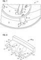
- FIG. 8 and 9 depict exemplary embodiments of a partial collar 26 in accordance with aspects of the present invention.
- FIG. 8 depicts a trailing edge collar 26B OD attachable to the trailing edge 30 of the strut shield 20 at the outer interface 22
- FIG. 9 depicts a trailing edge collar 26B ID attachable to the trailing edge 30 of the strut shield 20 at the inner interface 24.
- the collars 26B OD and 26B ID may be shaped so as to match a contour of the trailing edge 30 of the strut shield 20 at the interfaces 22 and 24 respectively.
- the leading edge collars 26A OD and 26A ID shown in FIG. 4-6 may be similarly configured in principle, and adapted to match a contour of the leading edge 28 of the strut shield 20 at the interfaces 22 and 24 respectively.
- each collar 26 comprises a first section 32 extending radially and configured to be aligned with the strut shield 20, and a second section 34 oriented at an angle to the first section 32 and configured to be aligned with the respective duct-wall 14, 16.
- the angle between the first section 32 and the second section 34 may correspond to the angle between the strut shield 20 and the duct-wall 14, 16 at the respective interface 22, 24.
- the angle between the first section 32 and the section 34 may be about 90 degrees, though not necessarily equal to 90 degrees, due to the conical geometry of the duct-walls 14, 16.
- the first section 32 extends radially inward from the second section 34, as shown in FIG. 8 .
- the first section 32 extends radially outward from the second section 34, as shown in FIG. 9 .
- the first section 32 of each collar 26 has a first edge 62, which may be joined to the strut shield 20 along a first joint 42 (see FIG. 4 ).
- the second section 34 of each collar 26 has a second edge 64, which may be joined to the respective duct-wall 14, 16 along a second joint 44 (see FIG. 4 ).
- the joints 42 and 44 comprise weld joints.
- each collar 26 meet at an intersection 40.
- the intersection 40 is formed by a smooth curve defined by a radius configured to distribute stresses at the respective interface 22, 24.
- the first joint 42 (along edge 62) is spaced from the intersection 40 along a first direction
- the second joint 44 (along edge 64) is spaced from the intersection 40 along a second direction non-parallel to the first direction.
- the illustrated collar design thus moves the weld joints away from the previously highly stressed areas to areas with lower stress, and provides a broad, smooth radius to better distribute stresses in these areas.
- each collar 26 extends only along a partial length of the perimeter of the strut shield 20 at the respective interface 22, 24.
- the strut shield 20 may be directly attached to the respective duct-wall 14, 16 for a remaining length of the perimeter of the strut shield 20 at the respective interface 22, 24, for example by welding.
- Each collar 26 extends partially along the perimeter of the strut shield 20 from a first end 52 to a second end 54 of the collar 26, as shown in FIG. 8 and 9 .
- the radius of the intersection 40 varies continuously between the first and second ends 52, 54.
- a maximum radius of the intersection 40 may be located at a location between the first and second ends 52, 54.
- the maximum radius may be located at the location of the trailing edge 30 of the strut shield 20.
- the maximum radius may be located at the location of the leading edge 28 of the strut shield 20.
- the variation of radius and the maximum radius of each collar 26 may be individually configured to distribute stresses from the regions of highest stress.
- the maximum radius of an individual collar 26 may depend on the location of the collar 26 (e.g., leading edge or trailing edge, inner or outer interface), span-wise height of the strut shield 20, and the material thickness of the strut shield 20, among other factors.
- the maximum radius of a collar 26 may be configured such that a ratio of a span-wise height of the strut shield 20 at the location of the maximum radius to the maximum radius lies in the range of 7-16.
- the maximum radius of a collar 26 may be configured such that a ratio of the maximum radius to a material thickness of the strut shield lies in the range of 4-10.
- each collar 26 may be desirably tailored relative to existing adjacent hardware to help further reduce stresses in specific areas. Accordingly, in one embodiment, the radius at the first end 52 and the radius at the second end 54 of the collar 26 are configured to respectively match the radius of a joint between the strut shield 20 and the respective duct-wall 14, 16 adjacent to the first end 52 and the radius of a joint between the strut shield 20 and the respective duct-wall 14, 16 adjacent to the second end 54 of the collar 26.
- the smooth curve forming the intersection 40 is defined by an inner radius on a first surface 46 facing a flowpath and an outer radius on a second surface 48 opposite to the first surface 46.
- radius as used in present specification, in phrases such as “variation of radius”, “maximum radius”, and the like, may refer to the inner radius, or the outer radius, or both.
- the aft end of the trailing edge collars may be configured as a radially extending flange 56, as shown in FIG. 10 .
- the flange 56 may be provided with bolt-holes 58 for attaching the duct 12 to a casing of a downstream turbine exhaust manifold.
- a further aspect of the present invention may be directed to a method to mitigate cracking in a turbine exhaust apparatus.
- the proposed method may be employed, for example, as part of an on-site field servicing of a gas turbine engine.
- one or more cutouts 36 may be formed, for example, by machining the strut shield 20 and the respective duct wall 14, 16.
- the cutouts 36 may be formed at the locations where the collars 26 are intended to be subsequently attached.
- the machining of the strut shield 20 and the respective duct-wall 14, 16 may be performed such that a peripheral contour of the cutout 36 as a whole corresponds to a peripheral contour of the respective collar 26 to be attached at the location of the cutout 36.
- the cutouts 36 are formed at the leading edge 28 and at the trailing edge 30 at the outer interface 22 as well as the inner interface 24 of each strut shield 20.
- Each strut shield 20 is, in this case, associated with four cutouts 36.
- a subsequent step comprises positioning the collars 26 within the cutouts 36 by aligning the first section 32 of each collar 26 with the strut shield 20 and aligning the second section 34 of the collar 26 with the respective duct-wall 14, 16.
- the first section 32 of the collar 26 is then joined to the strut shield 20 along a first joint 42 and the second section 34 of the collar 26 is joined to the respective duct-wall 14, 16 along a second joint 44.
- said joining may be carried out by welding.
- the resultant configuration of the exhaust apparatus 10 is shown in FIG. 4 .
Landscapes
- Engineering & Computer Science (AREA)
- Mechanical Engineering (AREA)
- General Engineering & Computer Science (AREA)
- Physics & Mathematics (AREA)
- Fluid Mechanics (AREA)
- Exhaust Silencers (AREA)
- Turbine Rotor Nozzle Sealing (AREA)
Description
- The present invention relates to gas turbine engines, and in particular to an exhaust apparatus of a gas turbine engine.
- An axial flow turbomachine, such as a gas turbine engine, typically includes a compressor section for compressing air, a combustor section for mixing the compressed air with fuel and igniting the mixture to form a hot working medium fluid, a turbine section for extracting power from the working medium fluid, and an exhaust apparatus located downstream of a last turbine stage for channeling the turbine exhaust flow. The turbine exhaust apparatus typically includes supporting structures, such as struts, distributed circumferentially in an annular flowpath. Each strut extends through an outer flowpath boundary and an inner flowpath boundary and is encapsulated by a protective strut shield. The strut shield may be joined to the outer and inner flowpath boundaries, for example by welding.
- In
US 2015/040393 A1 manufacture of a gas turbine exhaust diffuser shell is disclosed, wherein an opening in the shell is formed to receive a strut shield collar. - Further,
US 2015/143815 A1 discloses an integrated single-piece exhaust system (SPEX) with modular construction. The SPEX defines splined or curved exhaust path surfaces, such as a series of cylindrical and frusto-conical sections that mimic curves. - Furthermore,
US 2015/044046 A1 discloses a method for casting a collar for a heat shield of a strut in a gas turbine exhaust section. - Briefly, aspects of the present invention are directed to an apparatus and method for mitigating cracking in a gas turbine engine exhaust.
- According to a first aspect of the invention, an exhaust apparatus for a gas turbine is provided. The exhaust apparatus comprises an annular duct extending axially along a machine axis of the gas turbine. The annular duct is radially delimited by an outer duct-wall and an inner duct-wall. The exhaust apparatus also comprises a plurality of struts, which are circumferentially distributed within the annular duct. Each strut extends at least from the outer duct-wall to the inner duct-wall and is encapsulated in a respective strut shield. Each strut shield engages with the outer duct-wall along a first interface and engages with the inner duct-wall along a second interface. At least one of the first and second interfaces comprises at least one collar extending along a partial length of the perimeter of the strut shield at the respective interface. The collar comprises a first section extending radially and being aligned with the strut shield, and a second section oriented at an angle to the first section and being aligned with the respective duct-wall. The first section is attached to the strut shield along a first joint and the second section is attached to the respective duct-wall along a second joint. An intersection of the first and second sections is formed by a smooth curve defined by a radius configured to distribute stresses at the respective interface.
- According to a second aspect of the invention, a method is provided for servicing a gas turbine to mitigate cracking in an exhaust apparatus of the gas turbine. The exhaust apparatus includes an annular duct extending axially along a machine axis of the gas turbine. The annular duct is radially delimited by an outer duct-wall and an inner duct-wall. The exhaust apparatus also includes a plurality of struts, which are circumferentially distributed within the annular duct. Each strut extends at least from the outer duct-wall to the inner duct-wall and is encapsulated in a respective strut shield. Each strut shield engages with the outer duct-wall along a first interface and engages with the inner duct-wall along a second interface. The method comprises attaching at least one collar at the first interface and/or at the second interface. The collar is attached such that, after attachment, the collar extends along a partial length of the perimeter of the strut shield at the respective interface. The collar comprises a first section and a second section oriented at an angle to the first section. Attaching the collar comprises: aligning the first section with the strut shield and aligning the second section with the respective duct-wall, and subsequently joining the first section to the strut shield along a first joint and joining the second section to the respective duct-wall along a second joint. An intersection of the first and second sections is formed by a smooth curve defined by a radius configured to distribute stresses at the respective interface.
- The invention is shown in more detail by help of figures. The figures show preferred configurations and do not limit the scope of the invention.
-
FIG. 1 is a schematic diagram of a gas turbine engine where embodiments of the present invention may be incorporated; -
FIG. 2 is an axial front view of a known type of exhaust apparatus; -
FIG. 3 is a cross-sectional view along the section III-III inFIG. 2 ; -
FIG. 4 is a perspective view of an exhaust apparatus comprising partial collars according an embodiment of the present invention; -
FIG. 5 is a sectional plan view, looking in a radially outward direction, depicting a pair of partial collars at an interface of a strut shield with an outer duct-wall; -
FIG. 6 is a sectional plan view, looking in a radially inward direction, depicting a pair of partial collars at an interface of a strut shield with an inner duct-wall; -
FIG. 7 is a perspective view of an exhaust apparatus with machined cutouts prior to attachment of the partial collars; and -
FIG. 8-10 are perspective views of partial collars according to various embodiments of the present invention. - In the following detailed description of the preferred embodiments, reference is made to the accompanying drawings that form a part hereof, and in which is shown by way of illustration, and not by way of limitation, a specific embodiment in which the invention may be practiced. It is to be understood that other embodiments may be utilized and that changes may be made without departing from the scope of the present invention.
- Referring to
FIG. 1 , agas turbine engine 1 generally includes acompressor section 2, acombustor section 4, aturbine section 8 and anexhaust apparatus 10. In operation, thecompressor section 2 inductsambient air 3 and compresses it. The compressed air from thecompressor section 2 enters one or more combustors in thecombustor section 4. The compressed air is mixed with thefuel 5, and the air-fuel mixture is burned in the combustors to form a hot workingmedium fluid 6. The hot workingmedium fluid 6 is routed to theturbine section 8 where it is expanded through alternating rows of stationary airfoils and rotating airfoils and used to generate power that can drive a rotor 7. The expanded gas exiting theturbine section 8 is exhausted from theengine 1 via theexhaust apparatus 10 which is located downstream of a last turbine stage. - In one example, as shown in
FIG. 1 and 2 , theexhaust apparatus 10 may be configured as a diffuser, which may include a divergentannular duct 12 defining a flowpath for the exhaust gas and extending axially along a machine axis 9 of thegas turbine engine 1. Theannular duct 12 is delimited radially by an outer duct-wall 14 forming an outer flowpath boundary and an inner duct-wall 16 forming an inner flowpath boundary. The divergentannular duct 12 may serve to reduce the speed of the exhaust flow and thus increase the pressure difference of the exhaust gas expanding across the last stage of theturbine section 8. Theexhaust apparatus 10 further includes supporting structures, such asstruts 18, which are distributed circumferentially within theannular duct 12. Eachstrut 18 extends at least from the outer duct-wall 14 to the inner duct-wall 16. In the shown example, thestruts 18 further extend through the outer duct-wall 14 and the inner duct-wall 16. To protect thestruts 18 from high exhaust flowpath temperatures, eachstrut 18 is typically enclosed by astrut shield 20. Thestrut shield 20 may be aerodynamically shaped, having a leadingedge 28 and atrailing edge 30, as shown in the cross-sectional view inFIG. 3 . Referring toFIG. 2 , thestrut shield 20 encapsulates the radial extent of thestrut 18 between the outer duct-wall 14 and the inner duct-wall 16. Eachstrut shield 20 engages with the outer duct-wall 14 along anouter interface 22 and engages with the inner duct-wall 16 along aninner interface 24. Theinterfaces - It has been observed that strut shields in the turbine exhaust frequently exhibit cracking after extended operation in the field. These cracks tend to form in highly stressed regions, especially at the weld joints at the outer and
inner interfaces leading edge 28 and at the trailingedge 30 of thestrut shield 20 at theinterfaces - Embodiments of the present invention illustrated in
FIG. 4-10 are directed to aload distributing collar 26 attachable at any of theinterfaces collar 26 is designed so as to move the joints (typically weld joints) away from the highly stressed locations and provide a broad, smooth radius to better distribute stresses in these areas. A distinct feature of the proposed design is that thecollar 26 does not extend along the entire perimeter of thestrut shield 20 at therespective interface partial collar 26, as illustrated herein, may be easily installed on site during a field service. - In one embodiment, a
partial collar 26 may be provided at the locations having the highest stresses, for example at theleading edge 28 and/or at the trailingedge 30 of thestrut shield 20, at either or both of theinterfaces edge 28 and/or the trailingedge 30 may be redistributed to other locations of thestrut shield 20 and the respective duct-wall leading edge 28 and the trailingedge 30 may be increased due to decrease in weld material proportion at these locations. Equivalent strength of a flowpath cross-section refers the net strength of the flowpath cross-section considering the non-homogeneity (strength weakening elements), for example, due to weld seam heat affected zones, porosity, or other defects. Embodiments of the invention attempt to limit the extent of non-homogeneity, especially at the leading edge and/ trailing edge of the strut shield at the joints, due to smaller proportion of weld areas relative to conventional design approach, where the strut shield is joint to duct-wall directly by a weld at the leading and trailing edges. -
FIG. 4-6 illustrate an exemplary embodiment employing the proposed partial collar design. In the illustrated embodiment, eachstrut shield 20 is associated with fourcollars 26, which include a pair ofcollars 26 at eachinterface wall FIG. 5 and 6 , theouter interface 22 of thestrut shield 20 and the outer duct-wall 14 comprises: a leading edge collar 26AOD extending around the leadingedge 28 of thestrut shield 20, and a trailingedge collar 26BOD extending around the trailingedge 30 of thestrut shield 20. In addition, theinner interface 24 of the strut-shield 20 and the inner duct-wall 16 comprises: a leading edge collar 26AID extending around the leadingedge 28 of thestrut shield 20, and a trailingedge collar 26BID extending around the trailingedge 30 of thestrut shield 20. In other embodiments (not shown), acollar 26 may be provided at any one or more of the afore-mentioned locations, or at any other location with high stress which is prone to cracking. -
FIG. 8 and9 depict exemplary embodiments of apartial collar 26 in accordance with aspects of the present invention. In particular,FIG. 8 depicts a trailingedge collar 26BOD attachable to the trailingedge 30 of thestrut shield 20 at theouter interface 22, whileFIG. 9 depicts a trailingedge collar 26BID attachable to the trailingedge 30 of thestrut shield 20 at theinner interface 24. Thecollars edge 30 of thestrut shield 20 at theinterfaces FIG. 4-6 may be similarly configured in principle, and adapted to match a contour of the leadingedge 28 of thestrut shield 20 at theinterfaces - Referring to
FIG. 8 and9 , eachcollar 26 comprises afirst section 32 extending radially and configured to be aligned with thestrut shield 20, and asecond section 34 oriented at an angle to thefirst section 32 and configured to be aligned with the respective duct-wall first section 32 and thesecond section 34 may correspond to the angle between thestrut shield 20 and the duct-wall respective interface first section 32 and thesection 34 may be about 90 degrees, though not necessarily equal to 90 degrees, due to the conical geometry of the duct-walls collar 26 attached to theouter interface 22, thefirst section 32 extends radially inward from thesecond section 34, as shown inFIG. 8 . In case of acollar 26 attached to theinner interface 24, thefirst section 32 extends radially outward from thesecond section 34, as shown inFIG. 9 . Thefirst section 32 of eachcollar 26 has afirst edge 62, which may be joined to thestrut shield 20 along a first joint 42 (seeFIG. 4 ). Thesecond section 34 of eachcollar 26 has asecond edge 64, which may be joined to the respective duct-wall FIG. 4 ). In one embodiment, thejoints - The
first section 32 and thesecond section 34 of eachcollar 26 meet at anintersection 40. Theintersection 40 is formed by a smooth curve defined by a radius configured to distribute stresses at therespective interface intersection 40 along a first direction, and the second joint 44 (along edge 64) is spaced from theintersection 40 along a second direction non-parallel to the first direction. The illustrated collar design thus moves the weld joints away from the previously highly stressed areas to areas with lower stress, and provides a broad, smooth radius to better distribute stresses in these areas. As stated above, eachcollar 26 extends only along a partial length of the perimeter of thestrut shield 20 at therespective interface FIG. 4-6 , thestrut shield 20 may be directly attached to the respective duct-wall strut shield 20 at therespective interface - Each
collar 26 extends partially along the perimeter of thestrut shield 20 from afirst end 52 to asecond end 54 of thecollar 26, as shown inFIG. 8 and9 . In one embodiment, as illustrated herein, the radius of theintersection 40 varies continuously between the first and second ends 52, 54. In particular, a maximum radius of theintersection 40 may be located at a location between the first and second ends 52, 54. For the trailingedge collars FIG. 8 and9 respectively), the maximum radius may be located at the location of the trailingedge 30 of thestrut shield 20. Likewise, for the leading edge collars 26AOD and 26AID (not specifically shown), the maximum radius may be located at the location of the leadingedge 28 of thestrut shield 20. - The variation of radius and the maximum radius of each
collar 26 may be individually configured to distribute stresses from the regions of highest stress. For example, the maximum radius of anindividual collar 26 may depend on the location of the collar 26 (e.g., leading edge or trailing edge, inner or outer interface), span-wise height of thestrut shield 20, and the material thickness of thestrut shield 20, among other factors. In one embodiment, the maximum radius of acollar 26 may be configured such that a ratio of a span-wise height of thestrut shield 20 at the location of the maximum radius to the maximum radius lies in the range of 7-16. Independently or in addition, the maximum radius of acollar 26 may be configured such that a ratio of the maximum radius to a material thickness of the strut shield lies in the range of 4-10. It may be noted that in a divergent duct geometry, the span-wise height of the strut shield typically increases from the leading edge to the trailing edge. The material thickness of the strut shield may, in most cases, be assumed to be substantially constant. Moreover, radius of eachcollar 26 may be desirably tailored relative to existing adjacent hardware to help further reduce stresses in specific areas. Accordingly, in one embodiment, the radius at thefirst end 52 and the radius at thesecond end 54 of thecollar 26 are configured to respectively match the radius of a joint between thestrut shield 20 and the respective duct-wall first end 52 and the radius of a joint between thestrut shield 20 and the respective duct-wall second end 54 of thecollar 26. - In the present embodiment, as shown in
FIG. 8 and9 , the smooth curve forming theintersection 40 is defined by an inner radius on afirst surface 46 facing a flowpath and an outer radius on asecond surface 48 opposite to thefirst surface 46. In this case, the term "radius", as used in present specification, in phrases such as "variation of radius", "maximum radius", and the like, may refer to the inner radius, or the outer radius, or both. - In a further embodiment, the aft end of the trailing edge collars, particularly the trailing
edge collars 26BOD located at theouter interface 24, may be configured as aradially extending flange 56, as shown inFIG. 10 . Theflange 56 may be provided with bolt-holes 58 for attaching theduct 12 to a casing of a downstream turbine exhaust manifold. - A further aspect of the present invention may be directed to a method to mitigate cracking in a turbine exhaust apparatus. The proposed method may be employed, for example, as part of an on-site field servicing of a gas turbine engine.
- In a first step, as shown in
FIG. 7 , one ormore cutouts 36 may be formed, for example, by machining thestrut shield 20 and therespective duct wall cutouts 36 may be formed at the locations where thecollars 26 are intended to be subsequently attached. The machining of thestrut shield 20 and the respective duct-wall cutout 36 as a whole corresponds to a peripheral contour of therespective collar 26 to be attached at the location of thecutout 36. In the illustrated embodiment, thecutouts 36 are formed at theleading edge 28 and at the trailingedge 30 at theouter interface 22 as well as theinner interface 24 of eachstrut shield 20. Eachstrut shield 20 is, in this case, associated with fourcutouts 36. A subsequent step comprises positioning thecollars 26 within thecutouts 36 by aligning thefirst section 32 of eachcollar 26 with thestrut shield 20 and aligning thesecond section 34 of thecollar 26 with the respective duct-wall first section 32 of thecollar 26 is then joined to thestrut shield 20 along a first joint 42 and thesecond section 34 of thecollar 26 is joined to the respective duct-wall exhaust apparatus 10 is shown inFIG. 4 . - The above-described embodiments relate to a turbine exhaust cylinder positioned immediately downstream of a last turbine stage. It may be appreciated that aspects of the present invention may be applied to other areas in a turbine exhaust apparatus that involve supporting struts, such as in a turbine exhaust manifold positioned downstream of a turbine exhaust cylinder.
- While specific embodiments have been described in detail, those with ordinary skill in the art will appreciate that various modifications and alternative to those details could be developed in light of the overall teachings of the disclosure. Accordingly, the particular arrangements disclosed are meant to be illustrative only and not limiting as to the scope of the invention, which is to be given the full breadth of the appended claims.
Claims (15)
- An exhaust apparatus (10) for a gas turbine (1), comprising:an annular duct (12) extending axially along a machine axis (9) of the gas turbine (1), the annular duct (12) being radially delimited by an outer duct-wall (14) and an inner duct-wall (16),a plurality of struts (18), which are circumferentially distributed within the annular duct (12), wherein each strut (18) extends at least from the the outer duct-wall (14) to the inner duct-wall (16) and is encapsulated in a respective strut shield (20),wherein each strut shield (20) engages with the outer duct-wall (14) along a first interface (22) and engages with the inner duct-wall (16) along a second interface (24),wherein at least one of the first and second interfaces (22, 24) comprises:at least one collar (26) extending along a partial length of the perimeter of the strut shield (20) at the respective interface (22, 24), the collar (26) comprising a first section (32) extending radially and being aligned with the strut shield (20), and a second section (34) oriented at an angle to the first section (32) and being aligned with the respective duct-wall (14, 16), the first section (32) being attached to the strut shield (20) along a first joint (42) and the second section (34) being attached to the respective duct-wall (14, 16) along a second joint (44), andwherein an intersection (40) of the first and second sections (32, 34) is formed by a smooth curve defined by a radius configured to distribute stresses at the respective interface (22, 24).
- The exhaust apparatus (10) according to claim 1, wherein the first joint (42) is spaced from the intersection (40) along a first direction and the second joint (44) is spaced from the intersection (40) along a second direction which is non-parallel to the first direction.
- The exhaust apparatus (10) according to any of the preceding claims, wherein the strut shield (20) is directly attached to the respective duct-wall (14, 16) for a remaining length of the perimeter of the strut shield (20) at the respective interface (22, 24).
- The exhaust apparatus (10) according to any of the preceding claims, wherein said at least one collar (26) comprises one or both of:a leading edge collar (26AOD, 26AID) extending around a leading edge (28) of the strut shield (20) at the respective interface (22, 24), anda trailing edge collar (26BOD, 26BID) extending around a trailing edge (30) of the strut shield (20) at the respective interface (22, 24).
- The exhaust apparatus (10) according to claim 4, wherein both the first interface (22) and the second interface (24) comprise a respective leading edge collar (26AOD, 26AID) and a respective trailing edge collar (26BOD, 26BID).
- The exhaust apparatus (10) according to any of the preceding claims, wherein the first joint (42) and the second joint (44) each comprises a weld joint.
- The exhaust apparatus (10) according to any of the preceding claims, wherein the collar (26) extends partially along the perimeter of the strut shield (20) at the respective interface (22, 24) from a first end (52) to a second end (54) of the collar (26),
wherein the radius of the intersection (40) varies continuously between the first and second ends (52, 54). - The exhaust apparatus (10) according to claim 7, wherein a maximum radius of the intersection (40) is located at a location between the first and second ends (52, 54).
- The exhaust apparatus (10) according to claim 8, wherein the maximum radius is located at a leading edge (28) or at a trailing edge (30) of the strut shield (20).
- The exhaust apparatus (10) according to any of claims 8 and 9, wherein the maximum the radius of the intersection (40) is configured such that:a ratio of a span-wise height of the strut shield (20) at the location of the maximum radius to the maximum radius lies in the range of 7-16, and/ora ratio of the maximum radius to a material thickness of the strut shield lies in the range of 4-10.
- The exhaust apparatus (10) according to any of claims 7 to 10, wherein the radius of the intersection (40) at the first end (52) and the radius of the intersection (40) at the second end (54) of the collar (26) are configured to respectively match the radius of a joint between the strut shield (20) and the respective duct-wall (14, 16) adjacent to the first end (52) and a radius of a joint between the strut shield (20) and the respective duct-wall (14, 16) adjacent to the second end (54).
- The exhaust apparatus (10) according to any of the preceding claims, wherein the smooth curve forming the intersection (40) is defined by an inner radius on a first surface (46) facing a flowpath and an outer radius on a second surface (48) opposite to the first surface (46).
- The exhaust apparatus (10) according to any of the preceding claims, wherein the at least one collar (26) extends around a trailing edge (30) of the strut shield (20) at the first interface (22), and wherein an aft end of the collar (26) comprises a radially extending flange (56) provided with bolt holes (58) for attachment to a downstream exhaust manifold.
- A method for servicing a gas turbine (1) to mitigate cracking in an exhaust apparatus (10) of the gas turbine engine (1),the exhaust apparatus (10) comprising:an annular duct (12) extending axially along a machine axis (9) of the gas turbine (1), the annular duct (12) being radially delimited by an outer duct-wall (14) and an inner duct-wall (16),a plurality of struts (18), which are circumferentially distributed within the annular duct (12), wherein each strut (18) extends at least from the outer duct-wall (14) to the inner duct-wall (16) and is encapsulated in a respective strut shield (20),wherein each strut shield (20) engages with the outer duct-wall (14) along a first interface (22) and engages with the inner duct-wall (16) along a second interface (24),the method comprising:attaching at least one collar (26) at the first interface (22) and/or at the second interface (24), wherein after attachment, the collar (26) extends along a partial length of the perimeter of the strut shield (20) at the respective interface (22, 24), wherein the collar (26) comprises a first section (32) and a second section (34) oriented at an angle to the first section (32),wherein attaching the collar (26) comprises:aligning the first section (32) with the strut shield (20) and aligning the second section (34) with the respective duct-wall (14, 16), andjoining the first section (32) to the strut shield (20) along a first joint (42) and joining the second section (34) to the respective duct-wall (14, 16) along a second joint (44),wherein an intersection (40) of the first and second sections (32, 34) is formed by a smooth curve defined by a radius configured to distribute stresses at the respective interface (22, 24).
- The method according to claim 14, comprising:
prior to said attaching of the at least one collar (26), forming a cutout (36) in part on the strut shield (20) and in part on the respective duct-wall (14, 16), such that a peripheral contour of the cutout (36) as a whole corresponds to a peripheral contour of the collar (26).
Applications Claiming Priority (2)
| Application Number | Priority Date | Filing Date | Title |
|---|---|---|---|
| IN201811021368 | 2018-06-07 | ||
| PCT/US2019/035908 WO2019236928A1 (en) | 2018-06-07 | 2019-06-07 | Turbine exhaust crack mitigation using partial collars |
Publications (2)
| Publication Number | Publication Date |
|---|---|
| EP3797211A1 EP3797211A1 (en) | 2021-03-31 |
| EP3797211B1 true EP3797211B1 (en) | 2023-10-18 |
Family
ID=67003730
Family Applications (1)
| Application Number | Title | Priority Date | Filing Date |
|---|---|---|---|
| EP19733323.0A Active EP3797211B1 (en) | 2018-06-07 | 2019-06-07 | Turbine exhaust crack mitigation using partial collars |
Country Status (10)
| Country | Link |
|---|---|
| US (1) | US11248478B2 (en) |
| EP (1) | EP3797211B1 (en) |
| JP (1) | JP7082215B2 (en) |
| KR (1) | KR102479925B1 (en) |
| CN (1) | CN112204227B (en) |
| CA (1) | CA3102780C (en) |
| MX (1) | MX2020013216A (en) |
| MY (1) | MY200592A (en) |
| SA (1) | SA520420705B1 (en) |
| WO (1) | WO2019236928A1 (en) |
Families Citing this family (3)
| Publication number | Priority date | Publication date | Assignee | Title |
|---|---|---|---|---|
| JP7419002B2 (en) * | 2019-09-12 | 2024-01-22 | 三菱重工業株式会社 | Strut cover, exhaust casing and gas turbine |
| JP2025026820A (en) * | 2023-08-01 | 2025-02-26 | ゼネラル エレクトリック テクノロジー ゲゼルシャフト ミット ベシュレンクテル ハフツング | Vibration damping assembly for turbomachine exhaust diffuser - Patents.com |
| US12416249B1 (en) * | 2024-10-10 | 2025-09-16 | Pratt & Whitney Canada Corp. | Turbine support case with axial spokes and heat shields |
Family Cites Families (17)
| Publication number | Priority date | Publication date | Assignee | Title |
|---|---|---|---|---|
| JPS503852Y1 (en) * | 1971-07-20 | 1975-02-01 | ||
| US4993918A (en) * | 1989-05-19 | 1991-02-19 | United Technologies Corporation | Replaceable fairing for a turbine exhaust case |
| EP0550126A1 (en) * | 1992-01-02 | 1993-07-07 | General Electric Company | Thrust augmentor heat shield |
| US6866479B2 (en) * | 2003-05-16 | 2005-03-15 | Mitsubishi Heavy Industries, Ltd. | Exhaust diffuser for axial-flow turbine |
| FR2917458B1 (en) * | 2007-06-13 | 2009-09-25 | Snecma Sa | EXHAUST CASING HUB COMPRISING STRESS DISTRIBUTION RIBS |
| JP5118568B2 (en) * | 2008-07-22 | 2013-01-16 | 株式会社日立製作所 | Exhaust diffuser for gas turbine |
| US8408011B2 (en) * | 2009-04-30 | 2013-04-02 | Pratt & Whitney Canada Corp. | Structural reinforcement strut for gas turbine case |
| US20100275572A1 (en) * | 2009-04-30 | 2010-11-04 | Pratt & Whitney Canada Corp. | Oil line insulation system for mid turbine frame |
| DE102009034530A1 (en) * | 2009-07-23 | 2011-01-27 | Rolls-Royce Deutschland Ltd & Co Kg | Cross-sectional profile for the columns or the lining of columns and supply lines of a turbofan engine |
| US8776533B2 (en) * | 2010-03-08 | 2014-07-15 | United Technologies Corporation | Strain tolerant bound structure for a gas turbine engine |
| US20120198810A1 (en) * | 2011-02-04 | 2012-08-09 | General Electric Company, A New York Corporation | Strut airfoil design for low solidity exhaust gas diffuser |
| EP2971579B1 (en) * | 2013-03-11 | 2020-04-29 | United Technologies Corporation | Aft fairing sub-assembly for turbine exhaust case fairing |
| US20150044046A1 (en) * | 2013-08-07 | 2015-02-12 | Yevgeniy Shteyman | Manufacturing method for strut shield collar of gas turbine exhaust diffuser |
| US20150040393A1 (en) * | 2013-08-07 | 2015-02-12 | Yevgeniy Shteyman | Manufacturing method for exhaust diffuser shell with strut shield collar and joint flange |
| US20150044039A1 (en) * | 2013-08-08 | 2015-02-12 | Yevgeniy Shteyman | Exhaust diffuser shell with flange and manufacturing method |
| US9540956B2 (en) * | 2013-11-22 | 2017-01-10 | Siemens Energy, Inc. | Industrial gas turbine exhaust system with modular struts and collars |
| CN111852581A (en) * | 2020-07-24 | 2020-10-30 | 中国科学院工程热物理研究所 | A support plate structure suitable for force transmission of main bearing casing |
-
2019
- 2019-06-07 MX MX2020013216A patent/MX2020013216A/en unknown
- 2019-06-07 MY MYPI2020006388A patent/MY200592A/en unknown
- 2019-06-07 EP EP19733323.0A patent/EP3797211B1/en active Active
- 2019-06-07 KR KR1020207035048A patent/KR102479925B1/en active Active
- 2019-06-07 CN CN201980038172.9A patent/CN112204227B/en active Active
- 2019-06-07 JP JP2020567781A patent/JP7082215B2/en active Active
- 2019-06-07 WO PCT/US2019/035908 patent/WO2019236928A1/en not_active Ceased
- 2019-06-07 US US15/734,947 patent/US11248478B2/en active Active
- 2019-06-07 CA CA3102780A patent/CA3102780C/en active Active
-
2020
- 2020-12-03 SA SA520420705A patent/SA520420705B1/en unknown
Also Published As
| Publication number | Publication date |
|---|---|
| KR102479925B1 (en) | 2022-12-20 |
| CN112204227A (en) | 2021-01-08 |
| CA3102780A1 (en) | 2019-12-12 |
| MX2020013216A (en) | 2021-02-22 |
| KR20210002727A (en) | 2021-01-08 |
| JP7082215B2 (en) | 2022-06-07 |
| CN112204227B (en) | 2023-04-28 |
| US20210231021A1 (en) | 2021-07-29 |
| EP3797211A1 (en) | 2021-03-31 |
| SA520420705B1 (en) | 2023-02-20 |
| WO2019236928A1 (en) | 2019-12-12 |
| MY200592A (en) | 2024-01-04 |
| US11248478B2 (en) | 2022-02-15 |
| JP2021527178A (en) | 2021-10-11 |
| CA3102780C (en) | 2023-02-14 |
Similar Documents
| Publication | Publication Date | Title |
|---|---|---|
| US8240121B2 (en) | Retrofit dirt separator for gas turbine engine | |
| US10180084B2 (en) | Structural case for aircraft gas turbine engine | |
| EP1217169B1 (en) | Bolted joint for rotor disks | |
| US20110262277A1 (en) | Gas turbine composite workpiece to be used in gas turbine engine | |
| EP2817496B1 (en) | Turbine frame fairing for a gas turbine engine | |
| CA3102780C (en) | Turbine exhaust crack mitigation using partial collars | |
| US20150337687A1 (en) | Split cast vane fairing | |
| GB2534269A (en) | Fairing for a mixer of a nozzle of a dual-flow turbomachine | |
| EP1217231B1 (en) | Bolted joint for rotor disks and method of reducing thermal gradients therein | |
| US20050172485A1 (en) | Method of repair for cast article | |
| CN101206036A (en) | Burner Lining Replacement Panel | |
| CN101206037B (en) | Methods for repairing combustor liners | |
| EP3667018B1 (en) | Fan blade for a gas turbine engine | |
| US10240481B2 (en) | Angled cut to direct radiative heat load | |
| CN107366559B (en) | Systems and methods for gas turbine engines |
Legal Events
| Date | Code | Title | Description |
|---|---|---|---|
| STAA | Information on the status of an ep patent application or granted ep patent |
Free format text: STATUS: UNKNOWN |
|
| STAA | Information on the status of an ep patent application or granted ep patent |
Free format text: STATUS: THE INTERNATIONAL PUBLICATION HAS BEEN MADE |
|
| PUAI | Public reference made under article 153(3) epc to a published international application that has entered the european phase |
Free format text: ORIGINAL CODE: 0009012 |
|
| STAA | Information on the status of an ep patent application or granted ep patent |
Free format text: STATUS: REQUEST FOR EXAMINATION WAS MADE |
|
| 17P | Request for examination filed |
Effective date: 20201201 |
|
| AK | Designated contracting states |
Kind code of ref document: A1 Designated state(s): AL AT BE BG CH CY CZ DE DK EE ES FI FR GB GR HR HU IE IS IT LI LT LU LV MC MK MT NL NO PL PT RO RS SE SI SK SM TR |
|
| AX | Request for extension of the european patent |
Extension state: BA ME |
|
| DAV | Request for validation of the european patent (deleted) | ||
| DAX | Request for extension of the european patent (deleted) | ||
| GRAP | Despatch of communication of intention to grant a patent |
Free format text: ORIGINAL CODE: EPIDOSNIGR1 |
|
| STAA | Information on the status of an ep patent application or granted ep patent |
Free format text: STATUS: GRANT OF PATENT IS INTENDED |
|
| INTG | Intention to grant announced |
Effective date: 20230615 |
|
| GRAS | Grant fee paid |
Free format text: ORIGINAL CODE: EPIDOSNIGR3 |
|
| GRAA | (expected) grant |
Free format text: ORIGINAL CODE: 0009210 |
|
| STAA | Information on the status of an ep patent application or granted ep patent |
Free format text: STATUS: THE PATENT HAS BEEN GRANTED |
|
| AK | Designated contracting states |
Kind code of ref document: B1 Designated state(s): AL AT BE BG CH CY CZ DE DK EE ES FI FR GB GR HR HU IE IS IT LI LT LU LV MC MK MT NL NO PL PT RO RS SE SI SK SM TR |
|
| REG | Reference to a national code |
Ref country code: GB Ref legal event code: FG4D |
|
| REG | Reference to a national code |
Ref country code: CH Ref legal event code: EP |
|
| REG | Reference to a national code |
Ref country code: IE Ref legal event code: FG4D |
|
| REG | Reference to a national code |
Ref country code: DE Ref legal event code: R096 Ref document number: 602019039592 Country of ref document: DE |
|
| REG | Reference to a national code |
Ref country code: LT Ref legal event code: MG9D |
|
| REG | Reference to a national code |
Ref country code: NL Ref legal event code: MP Effective date: 20231018 |
|
| REG | Reference to a national code |
Ref country code: AT Ref legal event code: MK05 Ref document number: 1622656 Country of ref document: AT Kind code of ref document: T Effective date: 20231018 |
|
| PG25 | Lapsed in a contracting state [announced via postgrant information from national office to epo] |
Ref country code: NL Free format text: LAPSE BECAUSE OF FAILURE TO SUBMIT A TRANSLATION OF THE DESCRIPTION OR TO PAY THE FEE WITHIN THE PRESCRIBED TIME-LIMIT Effective date: 20231018 |
|
| PG25 | Lapsed in a contracting state [announced via postgrant information from national office to epo] |
Ref country code: GR Free format text: LAPSE BECAUSE OF FAILURE TO SUBMIT A TRANSLATION OF THE DESCRIPTION OR TO PAY THE FEE WITHIN THE PRESCRIBED TIME-LIMIT Effective date: 20240119 |
|
| PG25 | Lapsed in a contracting state [announced via postgrant information from national office to epo] |
Ref country code: IS Free format text: LAPSE BECAUSE OF FAILURE TO SUBMIT A TRANSLATION OF THE DESCRIPTION OR TO PAY THE FEE WITHIN THE PRESCRIBED TIME-LIMIT Effective date: 20240218 |
|
| PG25 | Lapsed in a contracting state [announced via postgrant information from national office to epo] |
Ref country code: LT Free format text: LAPSE BECAUSE OF FAILURE TO SUBMIT A TRANSLATION OF THE DESCRIPTION OR TO PAY THE FEE WITHIN THE PRESCRIBED TIME-LIMIT Effective date: 20231018 |
|
| PG25 | Lapsed in a contracting state [announced via postgrant information from national office to epo] |
Ref country code: AT Free format text: LAPSE BECAUSE OF FAILURE TO SUBMIT A TRANSLATION OF THE DESCRIPTION OR TO PAY THE FEE WITHIN THE PRESCRIBED TIME-LIMIT Effective date: 20231018 |
|
| PG25 | Lapsed in a contracting state [announced via postgrant information from national office to epo] |
Ref country code: ES Free format text: LAPSE BECAUSE OF FAILURE TO SUBMIT A TRANSLATION OF THE DESCRIPTION OR TO PAY THE FEE WITHIN THE PRESCRIBED TIME-LIMIT Effective date: 20231018 |
|
| PG25 | Lapsed in a contracting state [announced via postgrant information from national office to epo] |
Ref country code: LT Free format text: LAPSE BECAUSE OF FAILURE TO SUBMIT A TRANSLATION OF THE DESCRIPTION OR TO PAY THE FEE WITHIN THE PRESCRIBED TIME-LIMIT Effective date: 20231018 Ref country code: IS Free format text: LAPSE BECAUSE OF FAILURE TO SUBMIT A TRANSLATION OF THE DESCRIPTION OR TO PAY THE FEE WITHIN THE PRESCRIBED TIME-LIMIT Effective date: 20240218 Ref country code: GR Free format text: LAPSE BECAUSE OF FAILURE TO SUBMIT A TRANSLATION OF THE DESCRIPTION OR TO PAY THE FEE WITHIN THE PRESCRIBED TIME-LIMIT Effective date: 20240119 Ref country code: ES Free format text: LAPSE BECAUSE OF FAILURE TO SUBMIT A TRANSLATION OF THE DESCRIPTION OR TO PAY THE FEE WITHIN THE PRESCRIBED TIME-LIMIT Effective date: 20231018 Ref country code: BG Free format text: LAPSE BECAUSE OF FAILURE TO SUBMIT A TRANSLATION OF THE DESCRIPTION OR TO PAY THE FEE WITHIN THE PRESCRIBED TIME-LIMIT Effective date: 20240118 Ref country code: AT Free format text: LAPSE BECAUSE OF FAILURE TO SUBMIT A TRANSLATION OF THE DESCRIPTION OR TO PAY THE FEE WITHIN THE PRESCRIBED TIME-LIMIT Effective date: 20231018 Ref country code: PT Free format text: LAPSE BECAUSE OF FAILURE TO SUBMIT A TRANSLATION OF THE DESCRIPTION OR TO PAY THE FEE WITHIN THE PRESCRIBED TIME-LIMIT Effective date: 20240219 |
|
| PG25 | Lapsed in a contracting state [announced via postgrant information from national office to epo] |
Ref country code: SE Free format text: LAPSE BECAUSE OF FAILURE TO SUBMIT A TRANSLATION OF THE DESCRIPTION OR TO PAY THE FEE WITHIN THE PRESCRIBED TIME-LIMIT Effective date: 20231018 Ref country code: RS Free format text: LAPSE BECAUSE OF FAILURE TO SUBMIT A TRANSLATION OF THE DESCRIPTION OR TO PAY THE FEE WITHIN THE PRESCRIBED TIME-LIMIT Effective date: 20231018 Ref country code: PL Free format text: LAPSE BECAUSE OF FAILURE TO SUBMIT A TRANSLATION OF THE DESCRIPTION OR TO PAY THE FEE WITHIN THE PRESCRIBED TIME-LIMIT Effective date: 20231018 Ref country code: NO Free format text: LAPSE BECAUSE OF FAILURE TO SUBMIT A TRANSLATION OF THE DESCRIPTION OR TO PAY THE FEE WITHIN THE PRESCRIBED TIME-LIMIT Effective date: 20240118 Ref country code: LV Free format text: LAPSE BECAUSE OF FAILURE TO SUBMIT A TRANSLATION OF THE DESCRIPTION OR TO PAY THE FEE WITHIN THE PRESCRIBED TIME-LIMIT Effective date: 20231018 Ref country code: HR Free format text: LAPSE BECAUSE OF FAILURE TO SUBMIT A TRANSLATION OF THE DESCRIPTION OR TO PAY THE FEE WITHIN THE PRESCRIBED TIME-LIMIT Effective date: 20231018 |
|
| PG25 | Lapsed in a contracting state [announced via postgrant information from national office to epo] |
Ref country code: DK Free format text: LAPSE BECAUSE OF FAILURE TO SUBMIT A TRANSLATION OF THE DESCRIPTION OR TO PAY THE FEE WITHIN THE PRESCRIBED TIME-LIMIT Effective date: 20231018 |
|
| REG | Reference to a national code |
Ref country code: DE Ref legal event code: R097 Ref document number: 602019039592 Country of ref document: DE |
|
| PG25 | Lapsed in a contracting state [announced via postgrant information from national office to epo] |
Ref country code: CZ Free format text: LAPSE BECAUSE OF FAILURE TO SUBMIT A TRANSLATION OF THE DESCRIPTION OR TO PAY THE FEE WITHIN THE PRESCRIBED TIME-LIMIT Effective date: 20231018 |
|
| PG25 | Lapsed in a contracting state [announced via postgrant information from national office to epo] |
Ref country code: SK Free format text: LAPSE BECAUSE OF FAILURE TO SUBMIT A TRANSLATION OF THE DESCRIPTION OR TO PAY THE FEE WITHIN THE PRESCRIBED TIME-LIMIT Effective date: 20231018 |
|
| PG25 | Lapsed in a contracting state [announced via postgrant information from national office to epo] |
Ref country code: SM Free format text: LAPSE BECAUSE OF FAILURE TO SUBMIT A TRANSLATION OF THE DESCRIPTION OR TO PAY THE FEE WITHIN THE PRESCRIBED TIME-LIMIT Effective date: 20231018 Ref country code: SK Free format text: LAPSE BECAUSE OF FAILURE TO SUBMIT A TRANSLATION OF THE DESCRIPTION OR TO PAY THE FEE WITHIN THE PRESCRIBED TIME-LIMIT Effective date: 20231018 Ref country code: RO Free format text: LAPSE BECAUSE OF FAILURE TO SUBMIT A TRANSLATION OF THE DESCRIPTION OR TO PAY THE FEE WITHIN THE PRESCRIBED TIME-LIMIT Effective date: 20231018 Ref country code: EE Free format text: LAPSE BECAUSE OF FAILURE TO SUBMIT A TRANSLATION OF THE DESCRIPTION OR TO PAY THE FEE WITHIN THE PRESCRIBED TIME-LIMIT Effective date: 20231018 Ref country code: DK Free format text: LAPSE BECAUSE OF FAILURE TO SUBMIT A TRANSLATION OF THE DESCRIPTION OR TO PAY THE FEE WITHIN THE PRESCRIBED TIME-LIMIT Effective date: 20231018 Ref country code: CZ Free format text: LAPSE BECAUSE OF FAILURE TO SUBMIT A TRANSLATION OF THE DESCRIPTION OR TO PAY THE FEE WITHIN THE PRESCRIBED TIME-LIMIT Effective date: 20231018 |
|
| PLBE | No opposition filed within time limit |
Free format text: ORIGINAL CODE: 0009261 |
|
| STAA | Information on the status of an ep patent application or granted ep patent |
Free format text: STATUS: NO OPPOSITION FILED WITHIN TIME LIMIT |
|
| 26N | No opposition filed |
Effective date: 20240719 |
|
| PG25 | Lapsed in a contracting state [announced via postgrant information from national office to epo] |
Ref country code: SI Free format text: LAPSE BECAUSE OF FAILURE TO SUBMIT A TRANSLATION OF THE DESCRIPTION OR TO PAY THE FEE WITHIN THE PRESCRIBED TIME-LIMIT Effective date: 20231018 |
|
| PG25 | Lapsed in a contracting state [announced via postgrant information from national office to epo] |
Ref country code: SI Free format text: LAPSE BECAUSE OF FAILURE TO SUBMIT A TRANSLATION OF THE DESCRIPTION OR TO PAY THE FEE WITHIN THE PRESCRIBED TIME-LIMIT Effective date: 20231018 |
|
| PG25 | Lapsed in a contracting state [announced via postgrant information from national office to epo] |
Ref country code: MC Free format text: LAPSE BECAUSE OF FAILURE TO SUBMIT A TRANSLATION OF THE DESCRIPTION OR TO PAY THE FEE WITHIN THE PRESCRIBED TIME-LIMIT Effective date: 20231018 |
|
| PG25 | Lapsed in a contracting state [announced via postgrant information from national office to epo] |
Ref country code: LU Free format text: LAPSE BECAUSE OF NON-PAYMENT OF DUE FEES Effective date: 20240607 |
|
| GBPC | Gb: european patent ceased through non-payment of renewal fee |
Effective date: 20240607 |
|
| PG25 | Lapsed in a contracting state [announced via postgrant information from national office to epo] |
Ref country code: IE Free format text: LAPSE BECAUSE OF NON-PAYMENT OF DUE FEES Effective date: 20240607 |
|
| PG25 | Lapsed in a contracting state [announced via postgrant information from national office to epo] |
Ref country code: BE Free format text: LAPSE BECAUSE OF NON-PAYMENT OF DUE FEES Effective date: 20240630 |
|
| PG25 | Lapsed in a contracting state [announced via postgrant information from national office to epo] |
Ref country code: FR Free format text: LAPSE BECAUSE OF NON-PAYMENT OF DUE FEES Effective date: 20240630 |
|
| PG25 | Lapsed in a contracting state [announced via postgrant information from national office to epo] |
Ref country code: GB Free format text: LAPSE BECAUSE OF NON-PAYMENT OF DUE FEES Effective date: 20240607 |
|
| REG | Reference to a national code |
Ref country code: BE Ref legal event code: MM Effective date: 20240630 |
|
| PGFP | Annual fee paid to national office [announced via postgrant information from national office to epo] |
Ref country code: DE Payment date: 20250626 Year of fee payment: 7 |
|
| PG25 | Lapsed in a contracting state [announced via postgrant information from national office to epo] |
Ref country code: FI Free format text: LAPSE BECAUSE OF FAILURE TO SUBMIT A TRANSLATION OF THE DESCRIPTION OR TO PAY THE FEE WITHIN THE PRESCRIBED TIME-LIMIT Effective date: 20231019 |
|
| PGFP | Annual fee paid to national office [announced via postgrant information from national office to epo] |
Ref country code: IT Payment date: 20250623 Year of fee payment: 7 |
|
| PGFP | Annual fee paid to national office [announced via postgrant information from national office to epo] |
Ref country code: CH Payment date: 20250701 Year of fee payment: 7 |
|
| PG25 | Lapsed in a contracting state [announced via postgrant information from national office to epo] |
Ref country code: CY Free format text: LAPSE BECAUSE OF FAILURE TO SUBMIT A TRANSLATION OF THE DESCRIPTION OR TO PAY THE FEE WITHIN THE PRESCRIBED TIME-LIMIT; INVALID AB INITIO Effective date: 20190607 |
|
| PG25 | Lapsed in a contracting state [announced via postgrant information from national office to epo] |
Ref country code: HU Free format text: LAPSE BECAUSE OF FAILURE TO SUBMIT A TRANSLATION OF THE DESCRIPTION OR TO PAY THE FEE WITHIN THE PRESCRIBED TIME-LIMIT; INVALID AB INITIO Effective date: 20190607 |