EP3796851B1 - Systems for anchor placement - Google Patents
Systems for anchor placement Download PDFInfo
- Publication number
- EP3796851B1 EP3796851B1 EP19723613.6A EP19723613A EP3796851B1 EP 3796851 B1 EP3796851 B1 EP 3796851B1 EP 19723613 A EP19723613 A EP 19723613A EP 3796851 B1 EP3796851 B1 EP 3796851B1
- Authority
- EP
- European Patent Office
- Prior art keywords
- guide
- drill guide
- medical instrument
- drill
- anchor
- Prior art date
- Legal status (The legal status is an assumption and is not a legal conclusion. Google has not performed a legal analysis and makes no representation as to the accuracy of the status listed.)
- Active
Links
Images



Classifications
-
- A—HUMAN NECESSITIES
- A61—MEDICAL OR VETERINARY SCIENCE; HYGIENE
- A61B—DIAGNOSIS; SURGERY; IDENTIFICATION
- A61B17/00—Surgical instruments, devices or methods
- A61B17/16—Instruments for performing osteoclasis; Drills or chisels for bones; Trepans
- A61B17/17—Guides or aligning means for drills, mills, pins or wires
- A61B17/1739—Guides or aligning means for drills, mills, pins or wires specially adapted for particular parts of the body
- A61B17/1764—Guides or aligning means for drills, mills, pins or wires specially adapted for particular parts of the body for the knee
-
- A—HUMAN NECESSITIES
- A61—MEDICAL OR VETERINARY SCIENCE; HYGIENE
- A61B—DIAGNOSIS; SURGERY; IDENTIFICATION
- A61B17/00—Surgical instruments, devices or methods
- A61B17/04—Surgical instruments, devices or methods for suturing wounds; Holders or packages for needles or suture materials
- A61B17/0401—Suture anchors, buttons or pledgets, i.e. means for attaching sutures to bone, cartilage or soft tissue; Instruments for applying or removing suture anchors
-
- A—HUMAN NECESSITIES
- A61—MEDICAL OR VETERINARY SCIENCE; HYGIENE
- A61B—DIAGNOSIS; SURGERY; IDENTIFICATION
- A61B17/00—Surgical instruments, devices or methods
- A61B17/16—Instruments for performing osteoclasis; Drills or chisels for bones; Trepans
- A61B17/1662—Instruments for performing osteoclasis; Drills or chisels for bones; Trepans for particular parts of the body
- A61B17/1675—Instruments for performing osteoclasis; Drills or chisels for bones; Trepans for particular parts of the body for the knee
-
- A—HUMAN NECESSITIES
- A61—MEDICAL OR VETERINARY SCIENCE; HYGIENE
- A61B—DIAGNOSIS; SURGERY; IDENTIFICATION
- A61B17/00—Surgical instruments, devices or methods
- A61B17/16—Instruments for performing osteoclasis; Drills or chisels for bones; Trepans
- A61B17/1697—Instruments for performing osteoclasis; Drills or chisels for bones; Trepans specially adapted for wire insertion
-
- A—HUMAN NECESSITIES
- A61—MEDICAL OR VETERINARY SCIENCE; HYGIENE
- A61B—DIAGNOSIS; SURGERY; IDENTIFICATION
- A61B17/00—Surgical instruments, devices or methods
- A61B17/16—Instruments for performing osteoclasis; Drills or chisels for bones; Trepans
- A61B17/17—Guides or aligning means for drills, mills, pins or wires
-
- A—HUMAN NECESSITIES
- A61—MEDICAL OR VETERINARY SCIENCE; HYGIENE
- A61B—DIAGNOSIS; SURGERY; IDENTIFICATION
- A61B17/00—Surgical instruments, devices or methods
- A61B17/16—Instruments for performing osteoclasis; Drills or chisels for bones; Trepans
- A61B17/17—Guides or aligning means for drills, mills, pins or wires
- A61B17/1796—Guides or aligning means for drills, mills, pins or wires for holes for sutures or flexible wires
-
- A—HUMAN NECESSITIES
- A61—MEDICAL OR VETERINARY SCIENCE; HYGIENE
- A61B—DIAGNOSIS; SURGERY; IDENTIFICATION
- A61B17/00—Surgical instruments, devices or methods
- A61B17/56—Surgical instruments or methods for treatment of bones or joints; Devices specially adapted therefor
- A61B17/58—Surgical instruments or methods for treatment of bones or joints; Devices specially adapted therefor for osteosynthesis, e.g. bone plates, screws or setting implements
- A61B17/68—Internal fixation devices, including fasteners and spinal fixators, even if a part thereof projects from the skin
-
- A—HUMAN NECESSITIES
- A61—MEDICAL OR VETERINARY SCIENCE; HYGIENE
- A61B—DIAGNOSIS; SURGERY; IDENTIFICATION
- A61B17/00—Surgical instruments, devices or methods
- A61B17/56—Surgical instruments or methods for treatment of bones or joints; Devices specially adapted therefor
- A61B17/58—Surgical instruments or methods for treatment of bones or joints; Devices specially adapted therefor for osteosynthesis, e.g. bone plates, screws or setting implements
- A61B17/68—Internal fixation devices, including fasteners and spinal fixators, even if a part thereof projects from the skin
- A61B17/84—Fasteners therefor or fasteners being internal fixation devices
- A61B17/86—Pins or screws or threaded wires; nuts therefor
- A61B17/864—Pins or screws or threaded wires; nuts therefor hollow, e.g. with socket or cannulated
-
- A—HUMAN NECESSITIES
- A61—MEDICAL OR VETERINARY SCIENCE; HYGIENE
- A61B—DIAGNOSIS; SURGERY; IDENTIFICATION
- A61B17/00—Surgical instruments, devices or methods
- A61B17/56—Surgical instruments or methods for treatment of bones or joints; Devices specially adapted therefor
- A61B17/58—Surgical instruments or methods for treatment of bones or joints; Devices specially adapted therefor for osteosynthesis, e.g. bone plates, screws or setting implements
- A61B17/88—Osteosynthesis instruments; Methods or means for implanting or extracting internal or external fixation devices
- A61B17/8872—Instruments for putting said fixation devices against or away from the bone
-
- A—HUMAN NECESSITIES
- A61—MEDICAL OR VETERINARY SCIENCE; HYGIENE
- A61B—DIAGNOSIS; SURGERY; IDENTIFICATION
- A61B17/00—Surgical instruments, devices or methods
- A61B17/16—Instruments for performing osteoclasis; Drills or chisels for bones; Trepans
- A61B17/17—Guides or aligning means for drills, mills, pins or wires
- A61B17/1703—Guides or aligning means for drills, mills, pins or wires using imaging means, e.g. by X-rays
-
- A—HUMAN NECESSITIES
- A61—MEDICAL OR VETERINARY SCIENCE; HYGIENE
- A61B—DIAGNOSIS; SURGERY; IDENTIFICATION
- A61B17/00—Surgical instruments, devices or methods
- A61B17/56—Surgical instruments or methods for treatment of bones or joints; Devices specially adapted therefor
- A61B17/58—Surgical instruments or methods for treatment of bones or joints; Devices specially adapted therefor for osteosynthesis, e.g. bone plates, screws or setting implements
- A61B17/88—Osteosynthesis instruments; Methods or means for implanting or extracting internal or external fixation devices
- A61B17/8897—Guide wires or guide pins
-
- A—HUMAN NECESSITIES
- A61—MEDICAL OR VETERINARY SCIENCE; HYGIENE
- A61B—DIAGNOSIS; SURGERY; IDENTIFICATION
- A61B17/00—Surgical instruments, devices or methods
- A61B17/04—Surgical instruments, devices or methods for suturing wounds; Holders or packages for needles or suture materials
- A61B17/0401—Suture anchors, buttons or pledgets, i.e. means for attaching sutures to bone, cartilage or soft tissue; Instruments for applying or removing suture anchors
- A61B2017/0409—Instruments for applying suture anchors
-
- A—HUMAN NECESSITIES
- A61—MEDICAL OR VETERINARY SCIENCE; HYGIENE
- A61F—FILTERS IMPLANTABLE INTO BLOOD VESSELS; PROSTHESES; DEVICES PROVIDING PATENCY TO, OR PREVENTING COLLAPSING OF, TUBULAR STRUCTURES OF THE BODY, e.g. STENTS; ORTHOPAEDIC, NURSING OR CONTRACEPTIVE DEVICES; FOMENTATION; TREATMENT OR PROTECTION OF EYES OR EARS; BANDAGES, DRESSINGS OR ABSORBENT PADS; FIRST-AID KITS
- A61F2/00—Filters implantable into blood vessels; Prostheses, i.e. artificial substitutes or replacements for parts of the body; Appliances for connecting them with the body; Devices providing patency to, or preventing collapsing of, tubular structures of the body, e.g. stents
- A61F2/02—Prostheses implantable into the body
- A61F2/30—Joints
- A61F2/38—Joints for elbows or knees
Definitions
- the disclosure herein generally relates to medical instruments and, more particularly, to medical instruments for anchor placement.
- Existing methods of repairing a joint can involve inserting one or more anchors into the joint.
- a knee joint may suffer from a capsular disruption in which the knee capsule is separated from a knee joint structure (e.g., a tibia or femur).
- Repairing the capsular disruption can include inserting one or more anchors through the knee joint capsule and into the knee joint structure, so as to secure the knee joint capsule to the knee joint structure.
- current methods of repairing a joint by inserting one or more anchors into the joint have various drawbacks. For instance, it can be difficult to both efficiently and accurately insert the one or more anchors at the desired location.
- Systems in accordance with the present disclosure provide systems for anchor placement in a joint.
- the disclosed systems can be used during repair of a capsular disruption in which a knee joint capsule is secured to a knee joint structure with one or more anchors.
- WO01/82805 discloses a remotely aligned surgical drill guide.
- a medical instrument in an example, includes a drill guide having a proximal end and a distal end.
- a medical instrument can also include at least one reference guide attached to the drill guide, wherein the at least one reference guide is configured to be positioned at (i) a predetermined angle relative to the drill guide and (ii) a predetermined height from the distal end of the drill guide.
- the predetermined angle and the predetermined height may be predetermined to avoid particular anatomical structure(s) and/or to place an anchor in proximity of anatomical structure(s).
- a predetermined angle and a predetermined height can cause the drill guide to avoid the tibial plateau and to have proximity to a knee joint line when the reference guide aligns with a piercing rod positioned below a meniscus and above a tibial plateau.
- a medical instrument in another example, includes a drill guide to define or select an anchor placement location and an anchor placement angle.
- a medical instrument can also include a reference guide attached to the drill guide to define or select a reference line beneath a meniscus and above a tibial plateau, wherein the anchor placement location has a predetermined offset from the reference line, and wherein the anchor placement angle has a predetermined angle relative to the reference line.
- a method includes inserting a piercing rod through a knee capsule, beneath a meniscus, and above a tibial plateau.
- a method can also include advancing a reference guide attached to a drill guide over the piercing rod, wherein the drill guide defines or identifies an anchor placement location that has a predetermined offset from the piercing rod.
- a method can also include advancing a drill pin through the drill guide and drilling a hole into a joint structure at the defined anchor placement location.
- a method can further include advancing an anchor through the drill guide and placing the anchor in the hole.
- the disclosed medical instruments can be used in conjunction with surgical procedures that involve inserting one or more anchors into a joint.
- the disclosed instrument can be used in conjunction with surgical procedures in which the anchor(s) is to be inserted at an offset from a reference location in the joint that can be visualized during the procedure (e.g., visualized with an arthroscope).
- the disclosed instrument allows for inserting the anchor at a precise location and angle from the visualized reference location in the joint.
- An example surgical procedure in which the disclosed instrument can be used is described in U.S. Patent Application Serial No. 15/596,015 (hereinafter "the '015 application").
- the medical instrument 100 includes a drill guide 102 having proximal end 104 and a distal end 106.
- the medical instrument 100 also includes at least one reference guide 108 attached to the drill guide 102.
- the at least one reference guide 108 is positioned at a predetermined angle 110 relative to the drill guide 102 and a predetermined height 112 from the distal end 106 of the drill guide 102.
- the at least one reference guide 108 is also positioned at a predetermined lateral distance 114 (see Figure 1b ) from longitudinal axis 122 of the drill guide 102.
- the drill guide 102 and the at least one reference guide 108 comprise a medical-compliant metal, such as surgical-grade stainless steel. Other materials are possible as well.
- the medical instrument 100 also includes a handle 109 near the proximal end 104 of the drill guide 102. The handle 109 can provide an ergonomic grip to allow a surgeon to hold and maneuver the medical instrument 100 as needed during a surgical procedure.
- the drill guide 102 has a size and shape that allows the drill guide 102 to receive and surround a drill pin and/or an anchor.
- the drill guide 102 comprises a hollow tube.
- the hollow tube of the drill guide 102 is circular or substantially circular.
- the hollow tube of the drill guide 102 comprises a polygon shape, such as a triangle, square, pentagon, hexagon, heptagon, octagon, nonagon, or decagon. Other shapes are possible as well.
- the hollow tube of the drill guide 102 can include any suitable length, outer diameter, and inner diameter.
- the length is about 145 mm to about 215 mm (e.g., about 145, 155, 160, 165, 175, 180, 185, 190, 195, 200, 205, 210, or 215 mm (or any range from about 145 to about 215 mm)).
- the outer diameter is about 2.6 mm to about 5.6 mm (e.g., about 2.6, 2.8, 3.0, 3.5, 4.0, 4.5, 5.0, 5.5 or 5.6 mm (or any range from about 2.6 mm to about 5.6 mm)).
- the inner diameter is about 1.6 mm to about 4.1 mm (e.g., about 1.6, 2.0, 2.5, 3.0, 3.5, 4.0, and 4.1 mm (or any range from about 1.6 to 4.1 mm)).
- the outer and inner diameter of the hollow tube of the drill guide 102 are selected so that drill guide 102 is suitable for passage of drill pins and/or anchors without being too large so that it is unable to be used in the body.
- the at least one reference guide 108 has a size and shape that allows the at least one reference guide 108 to receive and surround a piercing rod.
- the reference guide 108 comprises a hollow tube.
- the hollow tube of the reference guide 108 is circular or substantially circular.
- the hollow tube of the reference guide 108 comprises a polygon shape, such as a triangle, square, pentagon, hexagon, heptagon, octagon, nonagon, or decagon. Other shapes are possible as well.
- the hollow tube of the reference guide 108 can include any suitable length, outer diameter, and inner diameter.
- the length is about 145 mm to about 215 mm (e.g., about 145, 155, 160, 165, 175, 180, 185, 190, 195, 200, 205, 210, or 215 mm (or any range from about 145 to about 215 mm)).
- the outer diameter is about 2.6 mm to about 5.6 mm (e.g., about 2.6, 2.8, 3.0, 3.5, 4.0, 4.5, 5.0, 5.5 or 5.6 mm (or any range about 2.6 mm to about 5.6 mm)).
- the inner diameter is about 1.6 mm to about 4.1 mm (e.g., about 1.6, 2.0, 2.5, 3.0, 3.5, 4.0, and 4.1 mm (or any range from about 1.6 to 4.1 mm)).
- the outer and inner diameter of the hollow tube of the reference guide 108 are selected so that the reference guide 108 is suitable for passage of a piercing rod without being too large so that it is unable to be used in the body.
- the piercing rod is a needle.
- the piercing rod is a wire.
- the piercing rod is a pin.
- Other piercing rods are possible as well.
- a piercing rod can have a diameter of about 1 mm to about 2 mm and a length of about 125 to about 225 mm.
- the tip 121 of the drill guide can include a rounded edge 123 and slits 125a-b.
- the slits can allow the user to visualize that the implant is fully seated in the bone by observing a laser line through the window.
- the medical instrument 100 can be used in conjunction with surgical procedures that involve inserting one or more anchors into a joint, and is particularly suitable for surgical procedures in which the anchor(s) is to be inserted at an offset from a reference location in the joint that can be visualized (e.g., visualized with an arthroscope or other suitable device).
- the at least one reference guide 108 defines or identifies a reference line 116
- the drill guide 102 defines or identifies both an anchor placement location 118 and an anchor placement angle 120.
- the anchor placement location 118 has a predetermined offset from the reference line 116.
- the predetermined offset includes a predetermined vertical distance below the reference line 116 a predetermined lateral distance from the reference line 116.
- the anchor placement angle 120 has a predetermined angle relative to the reference line 116.
- the medical instrument 100 can be used during a surgical procedure for repairing a capsular disruption in a knee joint, during which one or more anchors can be inserted through the knee joint capsule and into a knee joint structure (e.g., the tibia), so as to secure the knee joint capsule to the knee joint structure.
- a knee joint structure e.g., the tibia
- an arthroscope can be positioned to allow visualization of the knee joint capsule and the knee joint structure.
- a piercing rod can be placed through the skin and into the knee joint space, such that the piercing rod is below a meniscus and above a tibial plateau.
- the position of the piercing rod in the knee joint space can be visualized with the arthroscope to confirm that the piercing rod is below a meniscus and above a tibial plateau.
- the at least one reference guide 108 can then be advanced over the piercing rod until the drill guide 102 abuts the tibia.
- the predetermined angle and height of the at least one reference guide 108 cause the drill guide 102 to avoid a tibial plateau and to have proximity to a knee joint line when the reference guide 108 aligns with a piercing rod positioned below a meniscus and above a tibial plateau.
- the reference guide 108 aligns with the piercing rod when the reference guide 108 slides over the piercing rod.
- the proximity to the knee joint line provided by the angle and height of the reference guide 108 is a vertical distance below the knee joint line of about 1 mm to about 5 mm.
- Other distances are possible as well (e.g., about 0.1, 0.5, 1.0, 1.5, 2.0, 2.5, 3.0, 3.5, 4.0, 4.5, 5.0, 5.5, 6.0, 6.5, 7.0 mm, or more (or any range between about 0.1 and 7.0 mm)).
- Medical instrument 100 can be configured to provide any desired predetermined offset (i.e., vertical distance and lateral distance) of the anchor placement location 118 from the reference line 116.
- the at least one reference guide 108 has both a predetermined height 112 from the distal end 106 of the drill guide 102 and a predetermined lateral distance 114 from the longitudinal axis 122.
- the height 112 from the distal end 106 of the drill guide 102 is the distance from the distal end 106 along z-axis 130
- the lateral distance 114 from longitudinal axis 122 is the distance along the y-axis 132.
- the predetermined height 112 is about 1 mm to about 5 mm. Since the height from the distal end 106 of the drill guide 102 about 1 mm to about 5 mm, the anchor placement location 118 will be between about 1 mm and about 5 mm below the reference line 116. Other predetermined heights 112 are possible as well (e.g., about 0.1, 0.5, 1.0, 1.5, 2.0, 2.5, 3.0, 3.5, 4.0, 4.5, 5.0, 5.5, 6.0, 6.5, 7.0 mm, or more (or any range from about 0.1 to 7.0 mm)).
- the predetermined lateral distance 114 is about 0.5 mm to about 3 mm. This allows for defining an anchor placement location 118 that is laterally located (e.g., to the left or right along the y-axis 132) from about 1 mm to about 3 mm from the longitudinal axis 122.
- other predetermined lateral distances 114 are possible as well (e.g., about 0.1, 0.5, 1.0, 1.5, 2.0, 2.5, 3.0, 3.5, 4.0, 4.5, 5.0 mm, or more (or any range from about 0.1 to 5.0 mm)).
- Medical instrument 100 can also be configured to include any desired predetermined anchor placement angle 120 from the reference line 116.
- the predetermined angle 110 relative to the drill guide 102 is about 15 degrees to about 60 degrees.
- predetermined angle 110 and anchor placement angle 120 will be the same or substantially the same.
- the reference line 116 is parallel or substantially parallel to the knee joint line, and thus the inserted anchor will be angled about 15 degrees to about 60 degrees relative to the knee joint line.
- Other predetermined angles relative to the drill guide 102 are possible as well (e.g., about 5, 10, 15, 20, 25, 30, 35, 40, 45, 50, 55, 60, 65, 70, 75, or more (or any range about 5 degrees to 75 degrees)).
- the at least one reference guide 108 is fixed to the drill guide 102.
- the at least one reference guide 108 illustrated in Figures 1a-b is fixed to the drill guide 102.
- the at least one reference guide 108 can be fixed to the drill guide 102 in any suitable fashion.
- the at least one reference guide 108 is welded to the drill guide 102.
- the at least one reference guide 108 is fixed to the drill guide 102 with a fastener and/or an adhesive. Other examples are possible as well.
- the at least one reference guide 108 is non-movably fixed to the drill guide, such that the at least one reference guide 108 is not adjustable or moveable relative to the drill guide 102.
- the at least one reference guide 108 comprises an adjustable reference guide that is moveable relative to the drill guide 102.
- the at least one reference guide 108 can be configured to have an adjustable angle, an adjustable height from the distal end 106 of the drill guide 102, and/or an adjustable lateral distance 114 from the longitudinal axis 122 of the drill guide 102.
- the at least one reference guide 108 is an adjustable reference guide that is at least one of (i) moveable between a plurality of predetermined angles relative to the drill guide 102 or (ii) moveable between a plurality of predetermined heights from the distal end 106 of the drill guide 102.
- Figures 2 and 3 illustrate example adjustable reference guides.
- Figure 2 illustrates a distal end of drill guide 102a having an adjustable reference guide 108a.
- the adjustable reference guide 108a is hingedly attached to the drill guide via hinge 134, such that the adjustable reference guide 108a can adjust its angle relative to drill guide 102a.
- the adjustable reference guide 108a includes a lock to secure the adjustable reference guide 108a at a desired angle.
- the lock comprises a fastener (e.g., a screw, pin, etc.) that locks the reference guide 108a at a desired angle.
- Figure 3 illustrates a distal end of drill guide 102b having an adjustable reference guide 108b.
- the adjustable reference guide 108b is slidable relative to a longitudinal axis 122 of the drill guide 102b to adjust the height 112b from the distal end 106b of the drill guide 102b.
- the drill guide 102b includes a slit 124 in the body 124, and the reference guide 108b is moveable along the slit 124.
- the reference guide 108b can be locked in position at any desired height.
- the adjustable reference guide 108b includes a lock to secure the adjustable reference guide 108b at any position along the slit 124.
- the lock comprises a fastener (e.g., a screw, pin, etc.) that locks the reference guide 108b at a desired height.
- a fastener e.g., a screw, pin, etc.
- the adjustable reference guide 108b is also moveable between a plurality of predetermined angles relative to the drill guide 102.
- the adjustability of the at least one reference guide 108 can allow the surgeon to use a single instrument for the insertion of all of the anchors.
- the at least one reference guide 108 is a single reference guide.
- the medical instrument 100 can include two or more reference guides attached to the drill guide 102.
- Figure 4 illustrates a distal end of an example instrument 100c that includes drill guide 102c and reference guides 108c-d.
- Reference guide 108c is positioned at a first point 126 on the drill guide 102c
- reference guide 108d is positioned at a second point 128 on the drill guide 102c.
- the first point 126 and the second point 128 can be at any suitable location on the drill guide 102c. In this example, the first point 126 is located about 180 degrees from the second point 128.
- the references guides 108c-d have different predetermined heights from the distal end 106c of the drill guide 102c.
- the reference guides 108c-d can have the same predetermined height from the distal end 106c of the drill guide 102c.
- the first point 126 is located about 100 degrees to about 180 degrees from the second point 128.
- the two reference guides 108c-d can allow the surgeon to use a single instrument for the insertion of the two anchors.
- the drill guide 102 is a straight or substantially straight drill guide.
- the drill guide 102 could be a curved drill guide.
- An example medical instrument 100e having a curved drill guide 102e with attached reference guide 108e is shown in Figure 5 .
- the medical instrument in accordance with the present disclosure can be used in the surgical procedures described in the '015 application.
- the example methods thus can be similar in some respects to the method of repairing a capsular disruption described in the '015 application with reference to Figures 5 -14 at paragraphs [0037]-[0048].
- the '015 application describes use of a conventional drill guide used to guide a drill pin and to place two anchors in the knee joint structure.
- the '015 application describes inserting a spinal needle into the joint space, determining a certain distance distal to this spinal needle for capsular repair on the tibia, and placing a conventional drill guide at this determined distance to guide a drill pin for drilling a hole for the anchor.
- a surgeon would have to visually estimate the desired location at which to place the conventional drill guide and/or introduce another instrument to assist with placing the conventional drill guide at the desired location.
- one or more medical instruments 100 can instead be used to guide the drill pin and to place the two anchors at the desired location in the knee joint structure. Since the medical instrument 100 includes the reference guide attached to the drill guide, the medical instrument 100 allows for a more efficient and accurate anchor placement location than existing methods using a conventional drill guide.
- An example of a method in which the drill guide of the '015 application is replaced with one or more medical instruments 100 can involve inserting a piercing rod through a knee capsule, beneath a meniscus, and above a tibial plateau.
- the example method can also involve advancing a reference guide attached to a drill guide over the piercing rod, wherein the drill guide defines or identifies an anchor placement location that has a predetermined offset (i.e., a vertical distance and a lateral distance) from the piercing rod.
- the example method can also involve advancing a drill pin through the drill guide and drilling a hole into a joint structure at the defined anchor placement location.
- the example method can also involve advancing an anchor through the drill guide and placing the anchor in the hole. This example method is described in detail below with reference to Figures 6-11 . It should be understood that the many of the possibilities and permutations of the methods described in the '015 application can also apply to this example method described below.
- Figure 6 illustrates a knee 200 upon which the example method is performed.
- knee 200 is illustrated as a synthetic knee model.
- the knee 200 is a knee of a patient.
- the knee 200 is a cadaveric knee.
- the knee 200 includes a knee joint space 202 and a knee joint structure 204.
- the example method also involves inserting a piercing rod 206 into the knee joint space 202 and, in particular, through a knee capsule (not show), beneath meniscus 210, and above tibial plateau 211.
- An arthroscope 208 is also inserted into the knee joint space 202.
- the arthroscope 208 can allow for visualization of the knee joint space 202, the meniscus 210, and the knee joint structure 204.
- the example method also involves visualizing the piercing rod 206 with arthroscope 208 to confirm that the piercing rod 206 is located beneath meniscus 210 and above tibial plateau 211.
- one or more of the medical instruments in accordance with the present disclosure can then be used for placement of one or more anchors at a predetermined offset from the piercing rod 206.
- medical instrument 100 is used for defining an anchor placement location and angle.
- the method involves placing the piercing rod 206 within the reference guide 108 and advancing reference guide 108 attached to drill guide 102 over the piercing rod 206.
- the reference guide 108 thus surrounds the piercing rod 206, and the reference guide 108 can be advanced over the piercing rod 206 until the drill guide 102 abuts the knee joint structure 204 (see Figure 8 ).
- the drill guide 102 acts to define or select an anchor placement location 212 (see Figure 8 ) that has a predetermined offset from the piercing rod 206.
- the predetermined offset allows for the drill guide 102 avoiding the tibial plateau 211 but having proximity to a knee joint line 215 (see Figure 8 ) when the reference guide 108 aligns the piecing rod 206 below the meniscus 210 and above the tibial plateau 211.
- the method then involves advancing a drill pin 214 through the drill guide 102 (see Figure 9 ) and drilling a hole into joint structure 204 at the defined anchor placement location 212 (see Figure 8 ).
- the method then involves advancing an anchor through the drill guide 102 and placing the anchor in the hole. Any suitable anchors are possible.
- the anchor is a suture anchor (knotless or knotted; e.g., a SutureTak ® anchor, Quattro ® Link knotless anchors, Twinfix ® anchors, Bioraptor ® anchors, Spyromite ® anchors, Dynomite ® anchors, Osteoraptor ® anchors, Raptomite ® anchors, JuggerKnot ® anchors, JuggerKnotless ® anchors, etc.), a soft tissue anchor (e.g., Eclipse TM soft tissue anchor, Piton TM soft tissue fixation implant, etc.), or the like.
- the anchor is a staple. Other anchors are possible as well.
- the method can also involve inserting an additional anchor(s) into the joint structure 204.
- a second anchor is placed within about 2 cm of the first anchor.
- the second anchor is about 1 to about 2 or about 1 to about 1.5 cm from the first anchor.
- other distances between the anchors are possible as well (e.g., about 0.3, 0.4, 0.5, 0.6., 0.7, 0.8, 0.9, 1.0, 1.1, 1.2, 1.3, 1.4, 1.5, 1.6, 1.7, 1.8, 1.9, 2.0, 2.1, 2.2, 2.3, 2.4, 2.5, 2.6, 2.7, 2.8, 2.9, 3.0 cm, or more (or any range from about 0.3 to 3.0 cm)).
- the additional anchor(s) can be inserted into the joint structure 204 using the same medical instrument 100.
- medical instrument 100 also includes a second reference guide attached to the drill guide 102 (e.g., reference guide 108d shown in Figure 4 ).
- the example method involves advancing the second reference guide 108d attached to the drill guide 102 over the piercing rod 206.
- the piercing rod 206 remains in the same location as the piercing rod 206 was positioned during the drilling of the first hole.
- the piercing rod 206 is removed and subsequently reinserted into knee joint space 202.
- the method then involves advancing drill pin 214 through the drill guide 102 and drilling a second hole into the knee joint structure 204 at the defined second anchor placement location, and advancing a second anchor through the drill guide 102 and placing the second anchor into the second hole.
- the medical instrument 100 includes an adjustable reference guide (e.g., reference guide 108b shown in Figure 3 ).
- the method involves adjusting the reference guide 108b to a desired height to define or select a second anchor placement location.
- the reference guide 108b is removed from its alignment with the piercing rod 206 prior to the adjustment, and then re-aligned with the piercing rod 206 after the adjustment.
- the reference guide 108b can be adjusted while the reference guide 108b is aligned with the piercing rod 206.
- the method then involves advancing drill pin 214 through the drill guide 102 and drilling a second hole into the knee joint structure 204 at the defined second anchor placement location, and advancing a second anchor through the drill guide 102 and placing the second anchor into the second hole.
- the additional anchor(s) can be inserted into the joint structure 204 using a different medical instrument for anchor placement.
- a second instrument 220 is provided.
- the second instrument 220 includes a second reference guide 222 attached to a second drill guide 224.
- the second drill guide 224 defines a second anchor placement location that has a second predetermined offset from the piercing rod 206.
- the method then involves advancing the second reference guide 222 attached to the second drill guide 224 over the piercing rod 206.
- the method then involves advancing drill pin 214 through the second drill guide 224 and drilling a second hole into the knee joint structure 204 at the defined second anchor placement location, and advancing a second anchor through the second drill guide 224 and placing the second anchor into the second hole.
- the one or more anchors secure the joint capsule to the joint structure 204 at a point of capsular disruption.
- the instrument(s) 100 to be used in the surgical procedure can be selected based on the particular capsular disruption being repaired. For instance, in an example embodiment, the method involves determining a distance of the point of capsular disruption from a position beneath the meniscus 210 and above the tibial plateau 211, and adjusting a position of the reference guide 108 relative to the drill guide 102 based the determined distance. Adjusting the position of the reference guide 108 relative to the drill guide 102 based the determined distance can involve adjusting the reference guide 108a or 108b (see Figures 2 and 3 ) to the desired position relative to the drill guide 102. In the case where one or more instruments 100 are used that include a non-movably fixed reference guide (e.g., the reference guides illustrated in Figures 1ab and 4), a particular medical instrument 100 having the desired fixed reference guide can be selected and used during the surgical procedure.
- a non-movably fixed reference guide
- the example embodiment illustrated in Figures 6-11 includes inserting two anchors, more or fewer anchors are possible.
- three anchors are inserted into the knee joint structure 204 to secure the knee joint capsule to the knee joint structure 204.
- the first and second anchors are about 1 cm to about 2 cm apart, and the second and the third anchors are about 1 cm to about 2 cm apart.
- one anchor is used to secure the knee joint capsule to the knee joint structure 204.
- four or more anchors are used to secure the knee joint capsule to the knee joint structure 204.
- the anchors are inserted through the medial knee capsule and into the knee joint structure 204.
- the anchors are inserted through the lateral capsule and into the knee joint structure 204.
- the knee joint structure 204 into which the one or more anchors are inserted is the tibia.
- the knee joint structure 204 is the femur.
- the joint space 202 is a knee joint
- other joint spaces are possible as well.
- the joint space is a shoulder joint, an elbow joint, or a wrist joint.
- a method of selecting or defining an anchor placement location(s) comprises using at least one of the disclosed medical instruments to select or define the anchor placement location(s).
- the method of selecting or defining the anchor placement location(s) can comprise using medical instrument 100, 100c, 100e, and/or 220.
- the disclosed methods and systems described herein beneficially provide improved methods and systems for anchor placement in a joint.
- the disclosed methods and systems allow for easily and accurately inserting the one or more anchors at the desired anchor placement location and the desired anchor placement angle.
- the disclosed methods and systems beneficially improve both the efficiency and accuracy of anchor placement during surgical procedures for repairing a joint.
- joint space refers to the space in a joint between two bones.
- joint capsule refers to an envelope surrounding a synovial joint, where the joint capsule includes an outer fibrous layer or membrane and an inner synovial layer or membrane.
- articular cartilage covers the end surfaces of the bones that articulate within that joint.
- the joint capsule surrounds the bones joined by the synovial joint to provide strength and lubrication.
- knee joint capsule refers to an envelope that surrounds the knee joint and includes an outer fibrous layer or membrane and an inner synovial layer or membrane.
- the knee joint capsule surrounds the bones of the knee to provide strength and lubrication.
- knee joint structure refers to the portions of the knee enveloped by and surrounding the knee joint capsule.
- the knee joint structure includes meniscus, the tibia, the femur, tibial periosteum, and femoral periosteum.
- knee joint line refers to the line through the most distal points of the medial and lateral femoral condyles in the coronal plane, or the line through the most distal point of the femur perpendicular to the anatomical axis of the tibial shaft in the sagittal plane.
- tibial plateau refers to the smooth bony surface of either the lateral condyle or the medial condyle of the tibia that articulates with the corresponding condylar surface of the femur.
Landscapes
- Health & Medical Sciences (AREA)
- Surgery (AREA)
- Life Sciences & Earth Sciences (AREA)
- Orthopedic Medicine & Surgery (AREA)
- Molecular Biology (AREA)
- Animal Behavior & Ethology (AREA)
- Engineering & Computer Science (AREA)
- Biomedical Technology (AREA)
- Heart & Thoracic Surgery (AREA)
- Medical Informatics (AREA)
- Veterinary Medicine (AREA)
- Nuclear Medicine, Radiotherapy & Molecular Imaging (AREA)
- General Health & Medical Sciences (AREA)
- Public Health (AREA)
- Dentistry (AREA)
- Oral & Maxillofacial Surgery (AREA)
- Neurology (AREA)
- Rheumatology (AREA)
- Surgical Instruments (AREA)
- Prostheses (AREA)
Description
- The disclosure herein generally relates to medical instruments and, more particularly, to medical instruments for anchor placement.
- Existing methods of repairing a joint can involve inserting one or more anchors into the joint. For instance, a knee joint may suffer from a capsular disruption in which the knee capsule is separated from a knee joint structure (e.g., a tibia or femur). Repairing the capsular disruption can include inserting one or more anchors through the knee joint capsule and into the knee joint structure, so as to secure the knee joint capsule to the knee joint structure. However, current methods of repairing a joint by inserting one or more anchors into the joint have various drawbacks. For instance, it can be difficult to both efficiently and accurately insert the one or more anchors at the desired location.
- Systems in accordance with the present disclosure provide systems for anchor placement in a joint. In example embodiments, the disclosed systems can be used during repair of a capsular disruption in which a knee joint capsule is secured to a knee joint structure with one or more anchors. For example,
WO01/82805 - In an example, a medical instrument is described. A medical instrument includes a drill guide having a proximal end and a distal end. A medical instrument can also include at least one reference guide attached to the drill guide, wherein the at least one reference guide is configured to be positioned at (i) a predetermined angle relative to the drill guide and (ii) a predetermined height from the distal end of the drill guide. The predetermined angle and the predetermined height may be predetermined to avoid particular anatomical structure(s) and/or to place an anchor in proximity of anatomical structure(s). For example, a predetermined angle and a predetermined height can cause the drill guide to avoid the tibial plateau and to have proximity to a knee joint line when the reference guide aligns with a piercing rod positioned below a meniscus and above a tibial plateau.
- In another example, a medical instrument is described. A medical instrument includes a drill guide to define or select an anchor placement location and an anchor placement angle. A medical instrument can also include a reference guide attached to the drill guide to define or select a reference line beneath a meniscus and above a tibial plateau, wherein the anchor placement location has a predetermined offset from the reference line, and wherein the anchor placement angle has a predetermined angle relative to the reference line.
- In another example, a method is described, which is not part of the scope of protection. A method includes inserting a piercing rod through a knee capsule, beneath a meniscus, and above a tibial plateau. A method can also include advancing a reference guide attached to a drill guide over the piercing rod, wherein the drill guide defines or identifies an anchor placement location that has a predetermined offset from the piercing rod. A method can also include advancing a drill pin through the drill guide and drilling a hole into a joint structure at the defined anchor placement location. A method can further include advancing an anchor through the drill guide and placing the anchor in the hole.
-
-
Figure 1a illustrates a side view of an example medical instrument for anchor placement, according to an example embodiment. -
Figure 1b illustrates a front view of the distal end of the medical instrument ofFigure 1a , according to an example embodiment. -
Figure 2 illustrates a side view of a distal end of a medical instrument for anchor placement, according to an example embodiment. -
Figure 3 illustrates a perspective view of a distal end of a medical instrument for anchor placement, according to an example embodiment. -
Figure 4 illustrates a perspective view of a distal end of a medical instrument for anchor placement, according to an example embodiment. -
Figure 5 illustrates a perspective view of an example medical instrument for anchor placement, according to an example embodiment. -
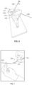
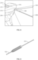
Figures 6-11 illustrate various example steps of method, according to an example which does not fall within the scope of the claims. - Disclosed embodiments will now be described more fully hereinafter with reference to the accompanying drawings, in which some, but not all of the disclosed embodiments are shown. Indeed, several different embodiments may be described and should not be construed as limited to the embodiments set forth herein.
- The disclosed medical instruments can be used in conjunction with surgical procedures that involve inserting one or more anchors into a joint. In an example, the disclosed instrument can be used in conjunction with surgical procedures in which the anchor(s) is to be inserted at an offset from a reference location in the joint that can be visualized during the procedure (e.g., visualized with an arthroscope). The disclosed instrument allows for inserting the anchor at a precise location and angle from the visualized reference location in the joint. An example surgical procedure in which the disclosed instrument can be used is described in
U.S. Patent Application Serial No. 15/596,015 (hereinafter "the '015 application"). - Referring now to
Figures 1a-b , an examplemedical instrument 100 for anchor placement is illustrated. Themedical instrument 100 includes adrill guide 102 havingproximal end 104 and adistal end 106. Themedical instrument 100 also includes at least onereference guide 108 attached to thedrill guide 102. The at least onereference guide 108 is positioned at apredetermined angle 110 relative to thedrill guide 102 and apredetermined height 112 from thedistal end 106 of thedrill guide 102. The at least onereference guide 108 is also positioned at a predetermined lateral distance 114 (seeFigure 1b ) fromlongitudinal axis 122 of thedrill guide 102. - Any suitable materials can be used for these components of the
medical instrument 100, including but not limited to metal, plastic, and/or rubber. In an example embodiment, thedrill guide 102 and the at least onereference guide 108 comprise a medical-compliant metal, such as surgical-grade stainless steel. Other materials are possible as well. In the example shown, themedical instrument 100 also includes ahandle 109 near theproximal end 104 of thedrill guide 102. Thehandle 109 can provide an ergonomic grip to allow a surgeon to hold and maneuver themedical instrument 100 as needed during a surgical procedure. - In general, the
drill guide 102 has a size and shape that allows thedrill guide 102 to receive and surround a drill pin and/or an anchor. In an example embodiment, thedrill guide 102 comprises a hollow tube. In an example embodiment, the hollow tube of thedrill guide 102 is circular or substantially circular. In other examples, the hollow tube of thedrill guide 102 comprises a polygon shape, such as a triangle, square, pentagon, hexagon, heptagon, octagon, nonagon, or decagon. Other shapes are possible as well. - The hollow tube of the
drill guide 102 can include any suitable length, outer diameter, and inner diameter. In an example embodiment, the length is about 145 mm to about 215 mm (e.g., about 145, 155, 160, 165, 175, 180, 185, 190, 195, 200, 205, 210, or 215 mm (or any range from about 145 to about 215 mm)). In an example embodiment, the outer diameter is about 2.6 mm to about 5.6 mm (e.g., about 2.6, 2.8, 3.0, 3.5, 4.0, 4.5, 5.0, 5.5 or 5.6 mm (or any range from about 2.6 mm to about 5.6 mm)). In an example embodiment, the inner diameter is about 1.6 mm to about 4.1 mm (e.g., about 1.6, 2.0, 2.5, 3.0, 3.5, 4.0, and 4.1 mm (or any range from about 1.6 to 4.1 mm)). The outer and inner diameter of the hollow tube of thedrill guide 102 are selected so thatdrill guide 102 is suitable for passage of drill pins and/or anchors without being too large so that it is unable to be used in the body. - In general, the at least one
reference guide 108 has a size and shape that allows the at least onereference guide 108 to receive and surround a piercing rod. In an example embodiment, thereference guide 108 comprises a hollow tube. In an example embodiment, the hollow tube of thereference guide 108 is circular or substantially circular. In other examples, the hollow tube of thereference guide 108 comprises a polygon shape, such as a triangle, square, pentagon, hexagon, heptagon, octagon, nonagon, or decagon. Other shapes are possible as well. - The hollow tube of the
reference guide 108 can include any suitable length, outer diameter, and inner diameter. In an example embodiment, the length is about 145 mm to about 215 mm (e.g., about 145, 155, 160, 165, 175, 180, 185, 190, 195, 200, 205, 210, or 215 mm (or any range from about 145 to about 215 mm)). In an example embodiment, the outer diameter is about 2.6 mm to about 5.6 mm (e.g., about 2.6, 2.8, 3.0, 3.5, 4.0, 4.5, 5.0, 5.5 or 5.6 mm (or any range about 2.6 mm to about 5.6 mm)). In an example embodiment, the inner diameter is about 1.6 mm to about 4.1 mm (e.g., about 1.6, 2.0, 2.5, 3.0, 3.5, 4.0, and 4.1 mm (or any range from about 1.6 to 4.1 mm)). The outer and inner diameter of the hollow tube of thereference guide 108 are selected so that thereference guide 108 is suitable for passage of a piercing rod without being too large so that it is unable to be used in the body. - In an example embodiment, the piercing rod is a needle. In another example embodiment, the piercing rod is a wire. In yet another example embodiment, the piercing rod is a pin. Other piercing rods are possible as well. A piercing rod can have a diameter of about 1 mm to about 2 mm and a length of about 125 to about 225 mm.
- With reference to
Figure 1B , thetip 121 of the drill guide can include arounded edge 123 andslits 125a-b. The slits can allow the user to visualize that the implant is fully seated in the bone by observing a laser line through the window. - The
medical instrument 100 can be used in conjunction with surgical procedures that involve inserting one or more anchors into a joint, and is particularly suitable for surgical procedures in which the anchor(s) is to be inserted at an offset from a reference location in the joint that can be visualized (e.g., visualized with an arthroscope or other suitable device). With reference toFigure 1a , the at least onereference guide 108 defines or identifies areference line 116, and thedrill guide 102 defines or identifies both ananchor placement location 118 and ananchor placement angle 120. Theanchor placement location 118 has a predetermined offset from thereference line 116. The predetermined offset includes a predetermined vertical distance below the reference line 116 a predetermined lateral distance from thereference line 116. Furthermore, theanchor placement angle 120 has a predetermined angle relative to thereference line 116. - In a particular example, the
medical instrument 100 can be used during a surgical procedure for repairing a capsular disruption in a knee joint, during which one or more anchors can be inserted through the knee joint capsule and into a knee joint structure (e.g., the tibia), so as to secure the knee joint capsule to the knee joint structure. In this surgical procedure, an arthroscope can be positioned to allow visualization of the knee joint capsule and the knee joint structure. Furthermore, a piercing rod can be placed through the skin and into the knee joint space, such that the piercing rod is below a meniscus and above a tibial plateau. The position of the piercing rod in the knee joint space can be visualized with the arthroscope to confirm that the piercing rod is below a meniscus and above a tibial plateau. The at least onereference guide 108 can then be advanced over the piercing rod until thedrill guide 102 abuts the tibia. The predetermined angle and height of the at least onereference guide 108 cause thedrill guide 102 to avoid a tibial plateau and to have proximity to a knee joint line when thereference guide 108 aligns with a piercing rod positioned below a meniscus and above a tibial plateau. Thereference guide 108 aligns with the piercing rod when thereference guide 108 slides over the piercing rod. - In an example embodiment, the proximity to the knee joint line provided by the angle and height of the
reference guide 108 is a vertical distance below the knee joint line of about 1 mm to about 5 mm. Other distances are possible as well (e.g., about 0.1, 0.5, 1.0, 1.5, 2.0, 2.5, 3.0, 3.5, 4.0, 4.5, 5.0, 5.5, 6.0, 6.5, 7.0 mm, or more (or any range between about 0.1 and 7.0 mm)). -
Medical instrument 100 can be configured to provide any desired predetermined offset (i.e., vertical distance and lateral distance) of theanchor placement location 118 from thereference line 116. As mentioned above, the at least onereference guide 108 has both apredetermined height 112 from thedistal end 106 of thedrill guide 102 and apredetermined lateral distance 114 from thelongitudinal axis 122. In the example ofFigure 1b , theheight 112 from thedistal end 106 of thedrill guide 102 is the distance from thedistal end 106 along z-axis 130, and thelateral distance 114 fromlongitudinal axis 122 is the distance along the y-axis 132. - In an example embodiment, the
predetermined height 112 is about 1 mm to about 5 mm. Since the height from thedistal end 106 of thedrill guide 102 about 1 mm to about 5 mm, theanchor placement location 118 will be between about 1 mm and about 5 mm below thereference line 116. Otherpredetermined heights 112 are possible as well (e.g., about 0.1, 0.5, 1.0, 1.5, 2.0, 2.5, 3.0, 3.5, 4.0, 4.5, 5.0, 5.5, 6.0, 6.5, 7.0 mm, or more (or any range from about 0.1 to 7.0 mm)). - In an example embodiment, the
predetermined lateral distance 114 is about 0.5 mm to about 3 mm. This allows for defining ananchor placement location 118 that is laterally located (e.g., to the left or right along the y-axis 132) from about 1 mm to about 3 mm from thelongitudinal axis 122. However, other predeterminedlateral distances 114 are possible as well (e.g., about 0.1, 0.5, 1.0, 1.5, 2.0, 2.5, 3.0, 3.5, 4.0, 4.5, 5.0 mm, or more (or any range from about 0.1 to 5.0 mm)). -
Medical instrument 100 can also be configured to include any desired predeterminedanchor placement angle 120 from thereference line 116. In an example, thepredetermined angle 110 relative to thedrill guide 102 is about 15 degrees to about 60 degrees. In the example ofFigures 1a-b , sincedrill guide 102 is substantially straight,predetermined angle 110 andanchor placement angle 120 will be the same or substantially the same. In an example, thereference line 116 is parallel or substantially parallel to the knee joint line, and thus the inserted anchor will be angled about 15 degrees to about 60 degrees relative to the knee joint line. Other predetermined angles relative to thedrill guide 102 are possible as well (e.g., about 5, 10, 15, 20, 25, 30, 35, 40, 45, 50, 55, 60, 65, 70, 75, or more (or any range about 5 degrees to 75 degrees)). - Within examples, the at least one
reference guide 108 is fixed to thedrill guide 102. For instance, the at least onereference guide 108 illustrated inFigures 1a-b is fixed to thedrill guide 102. The at least onereference guide 108 can be fixed to thedrill guide 102 in any suitable fashion. In an example, the at least onereference guide 108 is welded to thedrill guide 102. In another example, the at least onereference guide 108 is fixed to thedrill guide 102 with a fastener and/or an adhesive. Other examples are possible as well. - Within examples, the at least one
reference guide 108 is non-movably fixed to the drill guide, such that the at least onereference guide 108 is not adjustable or moveable relative to thedrill guide 102. Within other examples, the at least onereference guide 108 comprises an adjustable reference guide that is moveable relative to thedrill guide 102. The at least onereference guide 108 can be configured to have an adjustable angle, an adjustable height from thedistal end 106 of thedrill guide 102, and/or anadjustable lateral distance 114 from thelongitudinal axis 122 of thedrill guide 102. - In an example embodiment, the at least one
reference guide 108 is an adjustable reference guide that is at least one of (i) moveable between a plurality of predetermined angles relative to thedrill guide 102 or (ii) moveable between a plurality of predetermined heights from thedistal end 106 of thedrill guide 102. For instance,Figures 2 and 3 illustrate example adjustable reference guides.Figure 2 illustrates a distal end ofdrill guide 102a having anadjustable reference guide 108a. Theadjustable reference guide 108a is hingedly attached to the drill guide viahinge 134, such that theadjustable reference guide 108a can adjust its angle relative to drillguide 102a. In an example, theadjustable reference guide 108a includes a lock to secure theadjustable reference guide 108a at a desired angle. In an example, the lock comprises a fastener (e.g., a screw, pin, etc.) that locks thereference guide 108a at a desired angle. -
Figure 3 illustrates a distal end ofdrill guide 102b having anadjustable reference guide 108b. Theadjustable reference guide 108b is slidable relative to alongitudinal axis 122 of thedrill guide 102b to adjust theheight 112b from thedistal end 106b of thedrill guide 102b. In an example, thedrill guide 102b includes aslit 124 in thebody 124, and thereference guide 108b is moveable along theslit 124. Thereference guide 108b can be locked in position at any desired height. In an example embodiment, theadjustable reference guide 108b includes a lock to secure theadjustable reference guide 108b at any position along theslit 124. In an example, the lock comprises a fastener (e.g., a screw, pin, etc.) that locks thereference guide 108b at a desired height. In an example, theadjustable reference guide 108b is also moveable between a plurality of predetermined angles relative to thedrill guide 102. - In a surgical procedure involving insertion of a plurality of anchors, the adjustability of the at least one
reference guide 108 can allow the surgeon to use a single instrument for the insertion of all of the anchors. - In the examples of
Figures 1a-3 , the at least onereference guide 108 is a single reference guide. However, in other examples, themedical instrument 100 can include two or more reference guides attached to thedrill guide 102. For instance,Figure 4 illustrates a distal end of anexample instrument 100c that includesdrill guide 102c and reference guides 108c-d.Reference guide 108c is positioned at afirst point 126 on thedrill guide 102c, whereasreference guide 108d is positioned at asecond point 128 on thedrill guide 102c. In general, thefirst point 126 and thesecond point 128 can be at any suitable location on thedrill guide 102c. In this example, thefirst point 126 is located about 180 degrees from thesecond point 128. Furthermore, in this example, the references guides 108c-d have different predetermined heights from thedistal end 106c of thedrill guide 102c. However, in other examples, the reference guides 108c-d can have the same predetermined height from thedistal end 106c of thedrill guide 102c. Within examples, thefirst point 126 is located about 100 degrees to about 180 degrees from thesecond point 128. In a surgical procedure involving insertion of two anchors, the two reference guides 108c-d can allow the surgeon to use a single instrument for the insertion of the two anchors. - In the examples of
Figures 1a-4 , thedrill guide 102 is a straight or substantially straight drill guide. However, in other examples, thedrill guide 102 could be a curved drill guide. An examplemedical instrument 100e having a curved drill guide 102e with attachedreference guide 108e is shown inFigure 5 . - As examples, but not as part of the scope of protection, methods for anchor placement are disclosed. As indicated above, within example embodiments, the medical instrument in accordance with the present disclosure can be used in the surgical procedures described in the '015 application. The example methods thus can be similar in some respects to the method of repairing a capsular disruption described in the '015 application with reference to
Figures 5 -14 at paragraphs [0037]-[0048]. However, the '015 application describes use of a conventional drill guide used to guide a drill pin and to place two anchors in the knee joint structure. For instance, the '015 application describes inserting a spinal needle into the joint space, determining a certain distance distal to this spinal needle for capsular repair on the tibia, and placing a conventional drill guide at this determined distance to guide a drill pin for drilling a hole for the anchor. In practice, a surgeon would have to visually estimate the desired location at which to place the conventional drill guide and/or introduce another instrument to assist with placing the conventional drill guide at the desired location. In accordance with embodiments of the present disclosure, rather than using the drill guide of the '015 application to guide the drill pin and to place the two anchors, one or moremedical instruments 100 can instead be used to guide the drill pin and to place the two anchors at the desired location in the knee joint structure. Since themedical instrument 100 includes the reference guide attached to the drill guide, themedical instrument 100 allows for a more efficient and accurate anchor placement location than existing methods using a conventional drill guide. - An example of a method in which the drill guide of the '015 application is replaced with one or more
medical instruments 100 can involve inserting a piercing rod through a knee capsule, beneath a meniscus, and above a tibial plateau. The example method can also involve advancing a reference guide attached to a drill guide over the piercing rod, wherein the drill guide defines or identifies an anchor placement location that has a predetermined offset (i.e., a vertical distance and a lateral distance) from the piercing rod. The example method can also involve advancing a drill pin through the drill guide and drilling a hole into a joint structure at the defined anchor placement location. The example method can also involve advancing an anchor through the drill guide and placing the anchor in the hole. This example method is described in detail below with reference toFigures 6-11 . It should be understood that the many of the possibilities and permutations of the methods described in the '015 application can also apply to this example method described below. -
Figure 6 illustrates aknee 200 upon which the example method is performed. In this example,knee 200 is illustrated as a synthetic knee model. However, in other examples, theknee 200 is a knee of a patient. In yet other examples, theknee 200 is a cadaveric knee. Theknee 200 includes a knee joint space 202 and a kneejoint structure 204. The example method also involves inserting a piercingrod 206 into the knee joint space 202 and, in particular, through a knee capsule (not show), beneathmeniscus 210, and abovetibial plateau 211. Anarthroscope 208 is also inserted into the knee joint space 202. Thearthroscope 208 can allow for visualization of the knee joint space 202, themeniscus 210, and the kneejoint structure 204. The example method also involves visualizing the piercingrod 206 witharthroscope 208 to confirm that the piercingrod 206 is located beneathmeniscus 210 and abovetibial plateau 211. - With reference to
Figures 7-11 , one or more of the medical instruments in accordance with the present disclosure can then be used for placement of one or more anchors at a predetermined offset from the piercingrod 206. As seen inFigures 7-8 ,medical instrument 100 is used for defining an anchor placement location and angle. In particular, the method involves placing the piercingrod 206 within thereference guide 108 and advancingreference guide 108 attached to drillguide 102 over the piercingrod 206. Thereference guide 108 thus surrounds the piercingrod 206, and thereference guide 108 can be advanced over the piercingrod 206 until thedrill guide 102 abuts the knee joint structure 204 (seeFigure 8 ). Thedrill guide 102 acts to define or select an anchor placement location 212 (seeFigure 8 ) that has a predetermined offset from the piercingrod 206. The predetermined offset allows for thedrill guide 102 avoiding thetibial plateau 211 but having proximity to a knee joint line 215 (seeFigure 8 ) when thereference guide 108 aligns the piecingrod 206 below themeniscus 210 and above thetibial plateau 211. - With reference to
Figures 8-9 , the method then involves advancing adrill pin 214 through the drill guide 102 (seeFigure 9 ) and drilling a hole intojoint structure 204 at the defined anchor placement location 212 (seeFigure 8 ). With reference toFigure 8 , the method then involves advancing an anchor through thedrill guide 102 and placing the anchor in the hole. Any suitable anchors are possible. For instance, in an example embodiment, the anchor is a suture anchor (knotless or knotted; e.g., a SutureTak® anchor, Quattro® Link knotless anchors, Twinfix® anchors, Bioraptor® anchors, Spyromite® anchors, Dynomite® anchors, Osteoraptor® anchors, Raptomite® anchors, JuggerKnot® anchors, JuggerKnotless® anchors, etc.), a soft tissue anchor (e.g., Eclipse™ soft tissue anchor, Piton™ soft tissue fixation implant, etc.), or the like. In another example, the anchor is a staple. Other anchors are possible as well. - The method can also involve inserting an additional anchor(s) into the
joint structure 204. In an example embodiment, a second anchor is placed within about 2 cm of the first anchor. In a more particular example, the second anchor is about 1 to about 2 or about 1 to about 1.5 cm from the first anchor. However, other distances between the anchors are possible as well (e.g., about 0.3, 0.4, 0.5, 0.6., 0.7, 0.8, 0.9, 1.0, 1.1, 1.2, 1.3, 1.4, 1.5, 1.6, 1.7, 1.8, 1.9, 2.0, 2.1, 2.2, 2.3, 2.4, 2.5, 2.6, 2.7, 2.8, 2.9, 3.0 cm, or more (or any range from about 0.3 to 3.0 cm)). - In an example embodiment, the additional anchor(s) can be inserted into the
joint structure 204 using the samemedical instrument 100. For instance, in an example,medical instrument 100 also includes a second reference guide attached to the drill guide 102 (e.g.,reference guide 108d shown inFigure 4 ). In this embodiment, the example method involves advancing thesecond reference guide 108d attached to thedrill guide 102 over the piercingrod 206. In an example, the piercingrod 206 remains in the same location as the piercingrod 206 was positioned during the drilling of the first hole. In another example, the piercingrod 206 is removed and subsequently reinserted into knee joint space 202. The method then involves advancingdrill pin 214 through thedrill guide 102 and drilling a second hole into the kneejoint structure 204 at the defined second anchor placement location, and advancing a second anchor through thedrill guide 102 and placing the second anchor into the second hole. - In another example embodiment, the
medical instrument 100 includes an adjustable reference guide (e.g.,reference guide 108b shown inFigure 3 ). In this embodiment, the method involves adjusting thereference guide 108b to a desired height to define or select a second anchor placement location. In an example, thereference guide 108b is removed from its alignment with the piercingrod 206 prior to the adjustment, and then re-aligned with the piercingrod 206 after the adjustment. In another example, thereference guide 108b can be adjusted while thereference guide 108b is aligned with the piercingrod 206. The method then involves advancingdrill pin 214 through thedrill guide 102 and drilling a second hole into the kneejoint structure 204 at the defined second anchor placement location, and advancing a second anchor through thedrill guide 102 and placing the second anchor into the second hole. - In another example embodiment, the additional anchor(s) can be inserted into the
joint structure 204 using a different medical instrument for anchor placement. For instance, with reference toFigures 10 and 11 , asecond instrument 220 is provided. Thesecond instrument 220 includes asecond reference guide 222 attached to asecond drill guide 224. Thesecond drill guide 224 defines a second anchor placement location that has a second predetermined offset from the piercingrod 206. The method then involves advancing thesecond reference guide 222 attached to thesecond drill guide 224 over the piercingrod 206. The method then involves advancingdrill pin 214 through thesecond drill guide 224 and drilling a second hole into the kneejoint structure 204 at the defined second anchor placement location, and advancing a second anchor through thesecond drill guide 224 and placing the second anchor into the second hole. - As mentioned above, in an example embodiment, the one or more anchors secure the joint capsule to the
joint structure 204 at a point of capsular disruption. The instrument(s) 100 to be used in the surgical procedure can be selected based on the particular capsular disruption being repaired. For instance, in an example embodiment, the method involves determining a distance of the point of capsular disruption from a position beneath themeniscus 210 and above thetibial plateau 211, and adjusting a position of thereference guide 108 relative to thedrill guide 102 based the determined distance. Adjusting the position of thereference guide 108 relative to thedrill guide 102 based the determined distance can involve adjusting thereference guide Figures 2 and 3 ) to the desired position relative to thedrill guide 102. In the case where one ormore instruments 100 are used that include a non-movably fixed reference guide (e.g., the reference guides illustrated inFigures 1ab and 4), a particularmedical instrument 100 having the desired fixed reference guide can be selected and used during the surgical procedure. - Although the example embodiment illustrated in
Figures 6-11 includes inserting two anchors, more or fewer anchors are possible. For instance, in an example embodiment, three anchors are inserted into the kneejoint structure 204 to secure the knee joint capsule to the kneejoint structure 204. In an example, the first and second anchors are about 1 cm to about 2 cm apart, and the second and the third anchors are about 1 cm to about 2 cm apart. In another example, one anchor is used to secure the knee joint capsule to the kneejoint structure 204. In yet another example, four or more anchors are used to secure the knee joint capsule to the kneejoint structure 204. - Furthermore, in the example of
Figures 6-11 , the anchors are inserted through the medial knee capsule and into the kneejoint structure 204. However, in other example embodiments, the anchors are inserted through the lateral capsule and into the kneejoint structure 204. Still further, in the example embodiment ofFigures 6-11 , the kneejoint structure 204 into which the one or more anchors are inserted is the tibia. However, in other example embodiments, the kneejoint structure 204 is the femur. - Although the example embodiment illustrated in
Figures 6-11 illustrate the joint space 202 as a knee joint, other joint spaces are possible as well. For instance, in other examples, the joint space is a shoulder joint, an elbow joint, or a wrist joint. - In an example embodiment, a method of selecting or defining an anchor placement location(s) is disclosed. The method comprises using at least one of the disclosed medical instruments to select or define the anchor placement location(s). For instance, the method of selecting or defining the anchor placement location(s) can comprise using
medical instrument - The disclosed methods and systems described herein beneficially provide improved methods and systems for anchor placement in a joint. The disclosed methods and systems allow for easily and accurately inserting the one or more anchors at the desired anchor placement location and the desired anchor placement angle. As a result, the disclosed methods and systems beneficially improve both the efficiency and accuracy of anchor placement during surgical procedures for repairing a joint.
- The term "substantially" refers to a recited characteristic need not be achieved exactly, but that deviations or variations, including for example, tolerances, measurement error, measurement accuracy limitations and other factors known to persons having skill in the art, can occur in amounts that do not preclude the effect the characteristic was intended to provide.
- The term "about" in association with a numerical value refers to a value that can vary by 5%. For example, a value of "about 100" means 95 to 105 (or any value between 95 and 105).
- The term "joint space" refers to the space in a joint between two bones.
- The term "joint capsule" refers to an envelope surrounding a synovial joint, where the joint capsule includes an outer fibrous layer or membrane and an inner synovial layer or membrane. On the inside of the joint capsule, articular cartilage covers the end surfaces of the bones that articulate within that joint. The joint capsule surrounds the bones joined by the synovial joint to provide strength and lubrication.
- The term "knee joint capsule" refers to an envelope that surrounds the knee joint and includes an outer fibrous layer or membrane and an inner synovial layer or membrane. The knee joint capsule surrounds the bones of the knee to provide strength and lubrication.
- The term "knee joint structure" refers to the portions of the knee enveloped by and surrounding the knee joint capsule. In an example embodiment, the knee joint structure includes meniscus, the tibia, the femur, tibial periosteum, and femoral periosteum.
- The term "knee joint line" refers to the line through the most distal points of the medial and lateral femoral condyles in the coronal plane, or the line through the most distal point of the femur perpendicular to the anatomical axis of the tibial shaft in the sagittal plane.
- The term "tibial plateau" refers to the smooth bony surface of either the lateral condyle or the medial condyle of the tibia that articulates with the corresponding condylar surface of the femur.
- The description of the different advantageous arrangements has been presented for purposes of illustration and description, and is not intended to be exhaustive or limited to the embodiments in the form disclosed. Many modifications and variations will be apparent to those of ordinary skill in the art. Furthermore, different advantageous embodiments may describe different advantages as compared to other advantageous embodiments. The embodiment or embodiments selected are chosen and described in order to explain the principles of the embodiments, the practical application, and to enable others of ordinary skill in the art to understand the disclosure for various embodiments with various modifications as are suited to the particular use contemplated.
Claims (9)
- A medical instrument comprising:a drill guide (102) having a proximal end (104) and a distal end (106);at least one reference guide (108) attached to the drill guide (102), wherein the at least one reference guide (108) is a hollow tube, characterised in that
the hollow tube is positioned at (i) a predetermined angle (110) relative to the drill guide (102) of 15 degrees to 60 degrees and at (ii) a predetermined height (112) of 1 mm to 5 mm from the distal end (106) of the drill guide (102), wherein the predetermined angle (110) and the predetermined height (112) cause the drill guide (102) to avoid a tibial plateau (211) and to have proximity to a knee joint line (215) when the reference guide (108) aligns with a piercing rod (206) by sliding over the piercing rod (206), when the piercing rod (206) is positioned below a meniscus (210) and above a tibial plateau (211). - The medical instrument of claim 1, wherein the at least one reference guide (108) comprises an adjustable reference guide (108) that is at least one of (i) moveable between a plurality of predetermined angles (110) relative to the drill guide (102) or (ii) moveable between a plurality of predetermined heights (112) from the distal end (106) of the drill guide (102).
- The medical instrument of claim 2, wherein the adjustable reference guide (108) is hingedly attached to the drill guide (102).
- The medical instrument of claim 2, wherein the adjustable reference guide (108) is slidable relative to a longitudinal axis of the drill guide (102) to adjust the height (112) from the distal end (106) of the drill guide (102).
- The medical instrument of claim 2, wherein the adjustable reference guide (108) is (i) moveable between the plurality of predetermined angles (110) relative to the drill guide (102) and (ii) moveable between the plurality of predetermined heights (112) from the distal end (106) of the drill guide (102).
- The medical instrument of claim 1, wherein the drill guide (102) comprises a hollow tube.
- The medical instrument of claim 1, wherein the at least one reference guide (108) comprises:a first reference guide (108) positioned at a first point on the drill guide (102); anda second reference guide (108) positioned at a second point on the drill guide (102), wherein the first point is located between about 100 degrees to about 180 degrees from the second point.
- The medical instrument of claim 1, wherein the drill guide (102) is a curved drill guide (102).
- The medical instrument of claim 1:characterized in, thatthe drill guide (102) defines an anchor placement location and an anchor placement angle (120), andthe reference guide (108) defines a reference line beneath a meniscus (210) and above a tibial plateau (211), wherein the anchor placement location has a predetermined offset from the reference line, which includes a vertical distance from 1 mm to 5 mm and a lateral distance from 1 mm to 3 mm, and wherein the anchor placement angle (120) has a predetermined angle relative to the reference line, which is 15 degrees to 60 degrees.
Applications Claiming Priority (2)
| Application Number | Priority Date | Filing Date | Title |
|---|---|---|---|
| US15/985,159 US10828021B2 (en) | 2018-05-21 | 2018-05-21 | Systems and methods for anchor placement |
| PCT/US2019/030007 WO2019226286A1 (en) | 2018-05-21 | 2019-04-30 | Systems for anchor placement |
Publications (3)
| Publication Number | Publication Date |
|---|---|
| EP3796851A1 EP3796851A1 (en) | 2021-03-31 |
| EP3796851C0 EP3796851C0 (en) | 2023-06-07 |
| EP3796851B1 true EP3796851B1 (en) | 2023-06-07 |
Family
ID=66484207
Family Applications (1)
| Application Number | Title | Priority Date | Filing Date |
|---|---|---|---|
| EP19723613.6A Active EP3796851B1 (en) | 2018-05-21 | 2019-04-30 | Systems for anchor placement |
Country Status (7)
| Country | Link |
|---|---|
| US (2) | US10828021B2 (en) |
| EP (1) | EP3796851B1 (en) |
| JP (1) | JP7386182B2 (en) |
| KR (1) | KR20210013549A (en) |
| AU (1) | AU2019272432B2 (en) |
| NZ (1) | NZ768914A (en) |
| WO (1) | WO2019226286A1 (en) |
Families Citing this family (4)
| Publication number | Priority date | Publication date | Assignee | Title |
|---|---|---|---|---|
| US10828021B2 (en) * | 2018-05-21 | 2020-11-10 | Arthrex, Inc. | Systems and methods for anchor placement |
| US11224446B2 (en) | 2019-06-20 | 2022-01-18 | Imam Abdulrahman Bin Faisal University | Supracondylar bullet sleeve |
| KR20240125075A (en) * | 2022-01-26 | 2024-08-19 | 올림푸스 테루모 바이오머티리얼 가부시키가이샤 | Guide device |
| JP7510481B2 (en) * | 2022-11-28 | 2024-07-03 | 財團法人金屬工業研究發展中心 | Surgical instruments |
Family Cites Families (24)
| Publication number | Priority date | Publication date | Assignee | Title |
|---|---|---|---|---|
| US5147367A (en) * | 1991-02-22 | 1992-09-15 | Ellis Alfred B | Drill pin guide and method for orthopedic surgery |
| US5968050A (en) * | 1997-12-05 | 1999-10-19 | Smith & Nephew, Inc. | Positioning a tibial tunnel |
| US6342057B1 (en) | 2000-04-28 | 2002-01-29 | Synthes (Usa) | Remotely aligned surgical drill guide |
| US8439926B2 (en) | 2001-05-25 | 2013-05-14 | Conformis, Inc. | Patient selectable joint arthroplasty devices and surgical tools |
| US7618421B2 (en) | 2001-10-10 | 2009-11-17 | Howmedica Osteonics Corp. | Tools for femoral resection in knee surgery |
| US7029477B2 (en) | 2002-12-20 | 2006-04-18 | Zimmer Technology, Inc. | Surgical instrument and positioning method |
| US7488327B2 (en) | 2004-04-12 | 2009-02-10 | Synthes (U.S.A.) | Free hand drill guide |
| US7591850B2 (en) | 2005-04-01 | 2009-09-22 | Arthrocare Corporation | Surgical methods for anchoring and implanting tissues |
| US20070083210A1 (en) * | 2005-09-16 | 2007-04-12 | Zimmer Spine, Inc. | Apparatus and method for minimally invasive spine surgery |
| GB0605817D0 (en) | 2006-03-23 | 2006-05-03 | Imp Innovations Ltd | Reconstruction of anterior cruciate ligaments |
| US7686838B2 (en) | 2006-11-09 | 2010-03-30 | Arthrocare Corporation | External bullet anchor apparatus and method for use in surgical repair of ligament or tendon |
| US7998203B2 (en) | 2008-06-06 | 2011-08-16 | Blum Michael F | Total knee prosthesis and method for total knee arthroplasty |
| US9138219B2 (en) | 2010-12-29 | 2015-09-22 | Tarsus Medical Inc. | Methods and devices for treating a syndesmosis injury |
| US9084618B2 (en) | 2011-06-13 | 2015-07-21 | Biomet Manufacturing, Llc | Drill guides for confirming alignment of patient-specific alignment guides |
| US9636100B2 (en) | 2011-10-03 | 2017-05-02 | Smith & Nephew, Inc. | Tissue-to-bone reattachment |
| EP3388002B1 (en) | 2011-10-27 | 2019-11-20 | Smith & Nephew, Inc | Devices for performing knee arthroplasty |
| BR112015020016B1 (en) * | 2013-02-22 | 2021-09-21 | Sports Medicine Innovations Ag | SYSTEM FOR ANATOMICALLY CORRECT LIGAMENT RECONSTRUCTION |
| US10433880B2 (en) | 2013-03-15 | 2019-10-08 | Jcbd, Llc | Systems and methods for fusing a sacroiliac joint and anchoring an orthopedic appliance |
| US10028751B2 (en) | 2014-08-18 | 2018-07-24 | Medevice Solutions, LLC | Positioning and template system for preparing a femur for knee replacement |
| EP2989998B1 (en) | 2014-08-25 | 2017-12-06 | Arthrex, Inc. | Tibia cutting block |
| EP3253300B1 (en) | 2015-02-04 | 2021-12-15 | Smith & Nephew, Inc. | Articulating needle |
| US9955980B2 (en) | 2015-02-24 | 2018-05-01 | Biomet Sports Medicine, Llc | Anatomic soft tissue repair |
| AU2018244465B2 (en) | 2017-03-29 | 2023-11-02 | Smith & Nephew, Inc. | Angled suture passer and method of use thereof |
| US10828021B2 (en) * | 2018-05-21 | 2020-11-10 | Arthrex, Inc. | Systems and methods for anchor placement |
-
2018
- 2018-05-21 US US15/985,159 patent/US10828021B2/en active Active
-
2019
- 2019-04-30 AU AU2019272432A patent/AU2019272432B2/en active Active
- 2019-04-30 JP JP2020564426A patent/JP7386182B2/en active Active
- 2019-04-30 NZ NZ768914A patent/NZ768914A/en unknown
- 2019-04-30 EP EP19723613.6A patent/EP3796851B1/en active Active
- 2019-04-30 WO PCT/US2019/030007 patent/WO2019226286A1/en not_active Ceased
- 2019-04-30 KR KR1020207031131A patent/KR20210013549A/en not_active Ceased
-
2020
- 2020-10-05 US US17/062,839 patent/US11759197B2/en active Active
Also Published As
| Publication number | Publication date |
|---|---|
| WO2019226286A1 (en) | 2019-11-28 |
| EP3796851A1 (en) | 2021-03-31 |
| EP3796851C0 (en) | 2023-06-07 |
| US20210015477A1 (en) | 2021-01-21 |
| US20190350576A1 (en) | 2019-11-21 |
| NZ768914A (en) | 2024-11-29 |
| US10828021B2 (en) | 2020-11-10 |
| JP2021525117A (en) | 2021-09-24 |
| AU2019272432A1 (en) | 2020-11-12 |
| AU2019272432B2 (en) | 2024-10-10 |
| KR20210013549A (en) | 2021-02-04 |
| JP7386182B2 (en) | 2023-11-24 |
| US11759197B2 (en) | 2023-09-19 |
Similar Documents
| Publication | Publication Date | Title |
|---|---|---|
| US20220280169A1 (en) | Flexible ACL Instrumentation, Kit And Method | |
| US11759197B2 (en) | Systems and methods for anchor placement | |
| US5234435A (en) | Surgical method and apparatus | |
| RU2616994C2 (en) | System used in recovery of tissues | |
| EP2286769B1 (en) | Arthroscopic tibial sizer | |
| US10034674B2 (en) | Universal anterior cruciate ligament repair and reconstruction system | |
| US8328805B2 (en) | Percutaneous fixator and method of insertion | |
| EP2257240B1 (en) | A device for use during ligament reconstruction surgery | |
| US8361079B2 (en) | Method for drilling enlarged sections of angled osteal tunnels | |
| DE60131301T2 (en) | Rasp handle for minimally invasive total hip arthroplasty | |
| US20100121354A1 (en) | Device for the intraosteal seizing of sutures | |
| BR112018073530B1 (en) | ORTHOPEDIC SURGICAL INSTRUMENT SYSTEM | |
| WO2009134520A1 (en) | Ligament reconstruction guide assembly and methods of use | |
| WO2017151833A1 (en) | Soft tissue repair instruments and method | |
| US10632001B2 (en) | Orthopedic implant sizing instruments, systems, and methods | |
| US11344322B2 (en) | Minimally invasive surgical drill guide and method | |
| AU2013248269B2 (en) | Flexible acl instrumentation, kit and method | |
| WO2024137946A2 (en) | Measurement device and drill guide |
Legal Events
| Date | Code | Title | Description |
|---|---|---|---|
| STAA | Information on the status of an ep patent application or granted ep patent |
Free format text: STATUS: UNKNOWN |
|
| STAA | Information on the status of an ep patent application or granted ep patent |
Free format text: STATUS: THE INTERNATIONAL PUBLICATION HAS BEEN MADE |
|
| PUAI | Public reference made under article 153(3) epc to a published international application that has entered the european phase |
Free format text: ORIGINAL CODE: 0009012 |
|
| STAA | Information on the status of an ep patent application or granted ep patent |
Free format text: STATUS: REQUEST FOR EXAMINATION WAS MADE |
|
| 17P | Request for examination filed |
Effective date: 20201023 |
|
| AK | Designated contracting states |
Kind code of ref document: A1 Designated state(s): AL AT BE BG CH CY CZ DE DK EE ES FI FR GB GR HR HU IE IS IT LI LT LU LV MC MK MT NL NO PL PT RO RS SE SI SK SM TR |
|
| AX | Request for extension of the european patent |
Extension state: BA ME |
|
| DAV | Request for validation of the european patent (deleted) | ||
| DAX | Request for extension of the european patent (deleted) | ||
| STAA | Information on the status of an ep patent application or granted ep patent |
Free format text: STATUS: EXAMINATION IS IN PROGRESS |
|
| 17Q | First examination report despatched |
Effective date: 20211028 |
|
| GRAP | Despatch of communication of intention to grant a patent |
Free format text: ORIGINAL CODE: EPIDOSNIGR1 |
|
| STAA | Information on the status of an ep patent application or granted ep patent |
Free format text: STATUS: GRANT OF PATENT IS INTENDED |
|
| INTG | Intention to grant announced |
Effective date: 20221221 |
|
| GRAS | Grant fee paid |
Free format text: ORIGINAL CODE: EPIDOSNIGR3 |
|
| GRAA | (expected) grant |
Free format text: ORIGINAL CODE: 0009210 |
|
| STAA | Information on the status of an ep patent application or granted ep patent |
Free format text: STATUS: THE PATENT HAS BEEN GRANTED |
|
| AK | Designated contracting states |
Kind code of ref document: B1 Designated state(s): AL AT BE BG CH CY CZ DE DK EE ES FI FR GB GR HR HU IE IS IT LI LT LU LV MC MK MT NL NO PL PT RO RS SE SI SK SM TR |
|
| REG | Reference to a national code |
Ref country code: GB Ref legal event code: FG4D |
|
| REG | Reference to a national code |
Ref country code: CH Ref legal event code: EP Ref country code: AT Ref legal event code: REF Ref document number: 1572437 Country of ref document: AT Kind code of ref document: T Effective date: 20230615 |
|
| REG | Reference to a national code |
Ref country code: DE Ref legal event code: R096 Ref document number: 602019030203 Country of ref document: DE |
|
| U01 | Request for unitary effect filed |
Effective date: 20230630 |
|
| U07 | Unitary effect registered |
Designated state(s): AT BE BG DE DK EE FI FR IT LT LU LV MT NL PT SE SI Effective date: 20230717 |
|
| REG | Reference to a national code |
Ref country code: LT Ref legal event code: MG9D |
|
| PG25 | Lapsed in a contracting state [announced via postgrant information from national office to epo] |
Ref country code: NO Free format text: LAPSE BECAUSE OF FAILURE TO SUBMIT A TRANSLATION OF THE DESCRIPTION OR TO PAY THE FEE WITHIN THE PRESCRIBED TIME-LIMIT Effective date: 20230907 Ref country code: ES Free format text: LAPSE BECAUSE OF FAILURE TO SUBMIT A TRANSLATION OF THE DESCRIPTION OR TO PAY THE FEE WITHIN THE PRESCRIBED TIME-LIMIT Effective date: 20230607 |
|
| PG25 | Lapsed in a contracting state [announced via postgrant information from national office to epo] |
Ref country code: RS Free format text: LAPSE BECAUSE OF FAILURE TO SUBMIT A TRANSLATION OF THE DESCRIPTION OR TO PAY THE FEE WITHIN THE PRESCRIBED TIME-LIMIT Effective date: 20230607 Ref country code: HR Free format text: LAPSE BECAUSE OF FAILURE TO SUBMIT A TRANSLATION OF THE DESCRIPTION OR TO PAY THE FEE WITHIN THE PRESCRIBED TIME-LIMIT Effective date: 20230607 Ref country code: GR Free format text: LAPSE BECAUSE OF FAILURE TO SUBMIT A TRANSLATION OF THE DESCRIPTION OR TO PAY THE FEE WITHIN THE PRESCRIBED TIME-LIMIT Effective date: 20230908 |
|
| PG25 | Lapsed in a contracting state [announced via postgrant information from national office to epo] |
Ref country code: SK Free format text: LAPSE BECAUSE OF FAILURE TO SUBMIT A TRANSLATION OF THE DESCRIPTION OR TO PAY THE FEE WITHIN THE PRESCRIBED TIME-LIMIT Effective date: 20230607 |
|
| PG25 | Lapsed in a contracting state [announced via postgrant information from national office to epo] |
Ref country code: IS Free format text: LAPSE BECAUSE OF FAILURE TO SUBMIT A TRANSLATION OF THE DESCRIPTION OR TO PAY THE FEE WITHIN THE PRESCRIBED TIME-LIMIT Effective date: 20231007 |
|
| PG25 | Lapsed in a contracting state [announced via postgrant information from national office to epo] |
Ref country code: SM Free format text: LAPSE BECAUSE OF FAILURE TO SUBMIT A TRANSLATION OF THE DESCRIPTION OR TO PAY THE FEE WITHIN THE PRESCRIBED TIME-LIMIT Effective date: 20230607 Ref country code: SK Free format text: LAPSE BECAUSE OF FAILURE TO SUBMIT A TRANSLATION OF THE DESCRIPTION OR TO PAY THE FEE WITHIN THE PRESCRIBED TIME-LIMIT Effective date: 20230607 Ref country code: RO Free format text: LAPSE BECAUSE OF FAILURE TO SUBMIT A TRANSLATION OF THE DESCRIPTION OR TO PAY THE FEE WITHIN THE PRESCRIBED TIME-LIMIT Effective date: 20230607 Ref country code: IS Free format text: LAPSE BECAUSE OF FAILURE TO SUBMIT A TRANSLATION OF THE DESCRIPTION OR TO PAY THE FEE WITHIN THE PRESCRIBED TIME-LIMIT Effective date: 20231007 Ref country code: CZ Free format text: LAPSE BECAUSE OF FAILURE TO SUBMIT A TRANSLATION OF THE DESCRIPTION OR TO PAY THE FEE WITHIN THE PRESCRIBED TIME-LIMIT Effective date: 20230607 |
|
| PG25 | Lapsed in a contracting state [announced via postgrant information from national office to epo] |
Ref country code: PL Free format text: LAPSE BECAUSE OF FAILURE TO SUBMIT A TRANSLATION OF THE DESCRIPTION OR TO PAY THE FEE WITHIN THE PRESCRIBED TIME-LIMIT Effective date: 20230607 |
|
| REG | Reference to a national code |
Ref country code: DE Ref legal event code: R097 Ref document number: 602019030203 Country of ref document: DE |
|
| PLBE | No opposition filed within time limit |
Free format text: ORIGINAL CODE: 0009261 |
|
| STAA | Information on the status of an ep patent application or granted ep patent |
Free format text: STATUS: NO OPPOSITION FILED WITHIN TIME LIMIT |
|
| 26N | No opposition filed |
Effective date: 20240308 |
|
| U20 | Renewal fee for the european patent with unitary effect paid |
Year of fee payment: 6 Effective date: 20240408 |
|
| PG25 | Lapsed in a contracting state [announced via postgrant information from national office to epo] |
Ref country code: MC Free format text: LAPSE BECAUSE OF FAILURE TO SUBMIT A TRANSLATION OF THE DESCRIPTION OR TO PAY THE FEE WITHIN THE PRESCRIBED TIME-LIMIT Effective date: 20230607 |
|
| PG25 | Lapsed in a contracting state [announced via postgrant information from national office to epo] |
Ref country code: MC Free format text: LAPSE BECAUSE OF FAILURE TO SUBMIT A TRANSLATION OF THE DESCRIPTION OR TO PAY THE FEE WITHIN THE PRESCRIBED TIME-LIMIT Effective date: 20230607 |
|
| REG | Reference to a national code |
Ref country code: CH Ref legal event code: PL |
|
| PG25 | Lapsed in a contracting state [announced via postgrant information from national office to epo] |
Ref country code: CH Free format text: LAPSE BECAUSE OF NON-PAYMENT OF DUE FEES Effective date: 20240430 |
|
| U20 | Renewal fee for the european patent with unitary effect paid |
Year of fee payment: 7 Effective date: 20250310 |
|
| PG25 | Lapsed in a contracting state [announced via postgrant information from national office to epo] |
Ref country code: IE Free format text: LAPSE BECAUSE OF NON-PAYMENT OF DUE FEES Effective date: 20240430 |
|
| PG25 | Lapsed in a contracting state [announced via postgrant information from national office to epo] |
Ref country code: CY Free format text: LAPSE BECAUSE OF FAILURE TO SUBMIT A TRANSLATION OF THE DESCRIPTION OR TO PAY THE FEE WITHIN THE PRESCRIBED TIME-LIMIT; INVALID AB INITIO Effective date: 20190430 |
|
| PG25 | Lapsed in a contracting state [announced via postgrant information from national office to epo] |
Ref country code: HU Free format text: LAPSE BECAUSE OF FAILURE TO SUBMIT A TRANSLATION OF THE DESCRIPTION OR TO PAY THE FEE WITHIN THE PRESCRIBED TIME-LIMIT; INVALID AB INITIO Effective date: 20190430 |
|
| PGFP | Annual fee paid to national office [announced via postgrant information from national office to epo] |
Ref country code: GB Payment date: 20260313 Year of fee payment: 8 |
|
| U20 | Renewal fee for the european patent with unitary effect paid |
Year of fee payment: 8 Effective date: 20260310 |