EP3796756A1 - Electromagnetic heating device and cooking appliance - Google Patents
Electromagnetic heating device and cooking appliance Download PDFInfo
- Publication number
- EP3796756A1 EP3796756A1 EP20168309.1A EP20168309A EP3796756A1 EP 3796756 A1 EP3796756 A1 EP 3796756A1 EP 20168309 A EP20168309 A EP 20168309A EP 3796756 A1 EP3796756 A1 EP 3796756A1
- Authority
- EP
- European Patent Office
- Prior art keywords
- electromagnetic
- coil
- coils
- electromagnetic coils
- electromagnetic coil
- Prior art date
- Legal status (The legal status is an assumption and is not a legal conclusion. Google has not performed a legal analysis and makes no representation as to the accuracy of the status listed.)
- Granted
Links
Images






Classifications
-
- H—ELECTRICITY
- H05—ELECTRIC TECHNIQUES NOT OTHERWISE PROVIDED FOR
- H05B—ELECTRIC HEATING; ELECTRIC LIGHT SOURCES NOT OTHERWISE PROVIDED FOR; CIRCUIT ARRANGEMENTS FOR ELECTRIC LIGHT SOURCES, IN GENERAL
- H05B6/00—Heating by electric, magnetic or electromagnetic fields
- H05B6/02—Induction heating
- H05B6/10—Induction heating apparatus, other than furnaces, for specific applications
- H05B6/12—Cooking devices
- H05B6/1209—Cooking devices induction cooking plates or the like and devices to be used in combination with them
- H05B6/1245—Cooking devices induction cooking plates or the like and devices to be used in combination with them with special coil arrangements
- H05B6/1272—Cooking devices induction cooking plates or the like and devices to be used in combination with them with special coil arrangements with more than one coil or coil segment per heating zone
-
- H—ELECTRICITY
- H05—ELECTRIC TECHNIQUES NOT OTHERWISE PROVIDED FOR
- H05B—ELECTRIC HEATING; ELECTRIC LIGHT SOURCES NOT OTHERWISE PROVIDED FOR; CIRCUIT ARRANGEMENTS FOR ELECTRIC LIGHT SOURCES, IN GENERAL
- H05B6/00—Heating by electric, magnetic or electromagnetic fields
- H05B6/02—Induction heating
- H05B6/10—Induction heating apparatus, other than furnaces, for specific applications
- H05B6/12—Cooking devices
-
- H—ELECTRICITY
- H05—ELECTRIC TECHNIQUES NOT OTHERWISE PROVIDED FOR
- H05B—ELECTRIC HEATING; ELECTRIC LIGHT SOURCES NOT OTHERWISE PROVIDED FOR; CIRCUIT ARRANGEMENTS FOR ELECTRIC LIGHT SOURCES, IN GENERAL
- H05B2206/00—Aspects relating to heating by electric, magnetic, or electromagnetic fields covered by group H05B6/00
- H05B2206/02—Induction heating
- H05B2206/022—Special supports for the induction coils
-
- Y—GENERAL TAGGING OF NEW TECHNOLOGICAL DEVELOPMENTS; GENERAL TAGGING OF CROSS-SECTIONAL TECHNOLOGIES SPANNING OVER SEVERAL SECTIONS OF THE IPC; TECHNICAL SUBJECTS COVERED BY FORMER USPC CROSS-REFERENCE ART COLLECTIONS [XRACs] AND DIGESTS
- Y02—TECHNOLOGIES OR APPLICATIONS FOR MITIGATION OR ADAPTATION AGAINST CLIMATE CHANGE
- Y02B—CLIMATE CHANGE MITIGATION TECHNOLOGIES RELATED TO BUILDINGS, e.g. HOUSING, HOUSE APPLIANCES OR RELATED END-USER APPLICATIONS
- Y02B40/00—Technologies aiming at improving the efficiency of home appliances, e.g. induction cooking or efficient technologies for refrigerators, freezers or dish washers
Definitions
- the present disclosure relates to the technical field of cooking appliances, in particular to an electromagnetic heating device and a cooking appliance.
- the heating appliance In household electrical appliances, the heating appliance is typically circular, and magnetic field heating coil widely used is almost circular. Because the heating coil is wound in circle, the cooking appliance typically has a circular heating area. However, due to eddy-current concentration of the magnetic field on the appliance, the heating area cannot cover the projection area of the appliance corresponding to the coil, and the heating area is smaller than the effective area of the coil surface. This may result in a poor cooking experience, heating over-concentration and other problems.
- the present disclosure is to provide an electromagnetic heating device and a cooking appliance, aiming at improving the insufficient effective heating area and heating over-concentration in the related technology.
- an electromagnetic heating device which includes:
- an outer diameter of the second electromagnetic coil is smaller than an outer diameter of one of the first electromagnetic coils.
- the first electromagnetic coils are arranged in rows and columns.
- the second electromagnetic coil is arranged between the first electromagnetic coils of two adjacent columns and two adjacent rows.
- the electromagnetic coils include the second electromagnetic coil and the third electromagnetic coil, and the third electromagnetic coil and the second electromagnetic coil are concentric.
- the third electromagnetic coil includes a convex portion protruding inward, and the convex portion is extending into an outer part of a space between two adjacent first electromagnetic coils.
- the third electromagnetic coil surrounds the first electromagnetic coils.
- the electromagnetic coil includes two or more third electromagnetic coils.
- the third electromagnetic coils are arranged in an inner circle and in an outer circle, forming an annular area between two adjacent third electromagnetic coils, and the first electromagnetic coils are arranged in the annular area, and at least two first electromagnetic coils are surrounded by the third electromagnetic coil located in an innermost circle.
- the third electromagnetic coil is arranged in square; or,
- the third electromagnetic coil is arranged in square with an arc-like transition at corner; or, the third electromagnetic coil is arranged in circle.
- the third electromagnetic coil and the second electromagnetic coil are concentric.
- winding directions of the electromagnetic coils are the same, so as to allow the electromagnetic coils to generate magnetic fields in a same direction.
- the electromagnetic coils are connected in series.
- the electromagnetic coils are divided into at least two independently controlled electromagnetic coil groups.
- the electromagnetic coils further include the second electromagnetic coil and the third electromagnetic coil; the first electromagnetic coils are connected in series to form a first electromagnetic coil group, and the second electromagnetic coil and the third electromagnetic coil are connected in series to form a second electromagnetic coil group.
- the electromagnetic heating device includes a cooking base provided with a working surface for placing and heating a pot; a distance between an upper end of the electromagnetic coils and the working surface is d, and 5 mm ⁇ d ⁇ 8 mm.
- the coil disk is concave; or, the coil disk is flat.
- the present disclosure further provides a cooking appliance, which includes an electromagnetic heating device including:
- first electromagnetic coils are distributed and spaced on the coil disk to correspondingly form magnetic field centers.
- Such arrangement may overcome the problem of heating concentration in the related art.
- the first electromagnetic coils are distributed and spaced to form heating small centers taking each as a center, resulting in wider heating area and thus a larger effective heating area to improve the insufficient effective heating area in the related art.
- a second electromagnetic coil and/or a third electromagnetic coil are arranged. The second electromagnetic coil is arranged in a spaced area between the first electromagnetic coils, and the third electromagnetic coil is arranged around at least two of the first electromagnetic coils.
- the second electromagnetic coil can enhance the magnetic field strength of the spaced area between the first electromagnetic coils
- the third electromagnetic coil can enhance the magnetic field strength of the first electromagnetic coil wounded around its outside.
- the coupling coefficient between the magnetic field generated by the electromagnetic coils and the cooking appliance is increased through the second electromagnetic coil and/or the third electromagnetic coil to improve heating power.
- first and second are used for descriptive purposes only and cannot be understood as indicating or implying their relative importance or implicitly indicating the number of indicated technical features.
- features defining “first” and “second” may explicitly or implicitly include at least one of the features.
- the meaning of " and/or” appearing in the full text is to include three parallel schemes, taking " a and/or b" as some embodiments, including solution of a or b, or solution that both a and b satisfy at the same time.
- the technical solutions between the various embodiments may be combined with each other, but must be based on what one of ordinary skill in the art can achieve. When the combination of technical solutions is contradictory or impossible to achieve, it should be considered that the combination of such technical solutions does not exist and is not within the protection scope required by the present disclosure.
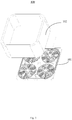
- the present disclosure provides a cooking appliance, as shown in Fig. 3 .
- the cooking appliance 100 includes an electromagnetic heating device 101 and a pot 102.
- the cooking appliance 100 can be but not limited to one of an induction cooker, an electric cooker, an electric pressure cooker and a cooking machine.
- Figs. 4 to 9 are the electromagnetic heating device according to embodiments provided by the present disclosure.
- the electromagnetic heating device provided by the present disclosure will be described in detail below with reference to the attached drawings.
- an electromagnetic heating device 101 which includes a coil disk 1 and electromagnetic coils 2.
- the shape or structure of the coil disk 1 should not be limited.
- the coil disk 1 may be arranged in a concave shape, as shown in Figs. 4 to 9 .
- the coil disk 1 is generally suitable for induction cookers.
- the electromagnetic coils 2 are arranged on the coil disk 1.
- the electromagnetic coils 2 include multiple first electromagnetic coils 2a which are distributed and spaced apart on the coil disk 1 to correspondingly form multiple independent winding areas and further correspondingly form multiple magnetic field centers.
- the first electromagnetic coils 2a Multiple heating areas will be formed by the first electromagnetic coils 2a, improving the heating over-concentration and insufficient effective heating area in the related art.
- areas blade portions
- the first electromagnetic coils 2a in such arrangement would decrease the coupling coefficient between the magnetic field generated by the first electromagnetic coils 2a and the cooker 102, resulting in a unsatisfactory heating power.
- the electromagnetic coils 2 further include a second electromagnetic coil 2b and/or a third electromagnetic coil 2c.
- the second electromagnetic coil 2b is disposed in a spaced area between the first electromagnetic coils 2a, and the third electromagnetic coil 2c surrounds at least two of the first electromagnetic coils 2a.
- a first electromagnetic coils 2a are distributed and spaced on the coil disk 1 to correspondingly form multiple magnetic field centers. Multiple heating centers are thus formed during heating process (as shown in Fig. 2 , four black areas are four heating centers).
- the problem can be solved of heating over-concentration in the related art.
- the first electromagnetic coils 2a are distributed and spaced to form multiple heating centers with various respective centers.
- the heating area is larger compared to the related art.
- multiple heating centers are distributed in a wider area, and the effective heating area can be increased to improve an insufficient effective heating area in the related art.
- the second electromagnetic coil 2b and/or the third electromagnetic coil 2c are arranged.
- the second electromagnetic coil 2b can enhance the magnetic field strength of the spaced area between the first electromagnetic coils 2a.
- the third electromagnetic coil 2c can enhance the magnetic field strength of at least two of the first electromagnetic coils 2a on their outer surroundings.
- the coupling coefficient between the magnetic field generated by the electromagnetic coils 2 and the pot can be increased to improve the heating power.
- the first electromagnetic coils 2a are distributed on the coil disk 1, and the specific distribution is not limited herein. Refer to Figs. 4 to 7 , in these embodiments, the first electromagnetic coils 2a are distributed in rows and columns. In some other embodiments, as shown in Fig. 8 , the first electromagnetic coils 2a may be distributed circumferentially in annular shape. Obviously, the distribution of the first electromagnetic coils 2a depends on the requirements of the effective heating area. For example, if the effective heating area is circular, it is preferable that the first electromagnetic coils 2a are distributed annularly. While with respect to the effective heating area which is square, etc. correspondingly, the first electromagnetic coils 2a are arranged in a square. A specific example is provided in a matrix arrangement, specifically in a matrix arrangement of 2 rows ⁇ 2 columns as shown in Figs. 4 to 7 .
- the electromagnetic coils 2 further include the second electromagnetic coil 2b and/or the third electromagnetic coil 2c.
- the electromagnetic coils 2 include the first electromagnetic coil 2a and the third electromagnetic coil 2c; as shown in Fig. 5 , the electromagnetic coils 2 include the first electromagnetic coil 2a and the second electromagnetic coil 2b; and as shown in Fig. 6 , the electromagnetic coils 2 include the first electromagnetic coil 2a, the second electromagnetic coil 2b, and the third electromagnetic coil 2c. All these variations would be described below with reference to the attached drawings respectively.
- the electromagnetic coils 2 further include the second electromagnetic coils 2b, which are distributed in the spaced area between the first electromagnetic coils 2a.
- the second electromagnetic coil 2b can compensate the magnetic field in the spaced area to further improve the heating uniformity.
- the coupling coefficient between the magnetic field generated by the electromagnetic coils 2 and the pot 102 can be increased to improve the heating power.
- the electromagnetic coil 2 is not limited to being circular, that is, the first electromagnetic coil 2a and the second electromagnetic coil 2b are not limited to being circular.
- the outer diameters of the second electromagnetic coil 2b and the first electromagnetic coil 2a are the corresponding diameter; and if they are non-circular, the outer diameter is considered as the diameter of the circumscribed circle of the first electromagnetic coils 2a or the second electromagnetic coil 2b.
- the first electromagnetic coils 2a are distributed in rows and columns, and the second electromagnetic coils 2b are disposed between the first electromagnetic coils 2a of two adjacent columns and two adjacent rows.
- the arrangement is not limited to above description. If the first electromagnetic coils 2a are annularly distributed, the second electromagnetic coils 2b may be distributed inside the annular area defined by the first electromagnetic coils 2a, as shown in Fig. 8 .
- the first electromagnetic coils 2a multiple heating areas will be formed by the first electromagnetic coils 2a and problems are solved regarding heating over-concentration and insufficient effective heating area in the related art.
- a poor magnetic field area will be formed in the exterior area of the first electromagnetic coils 2a.
- a poor heating area will be formed.
- the arrangement of the first electromagnetic coils 2a decreases the coupling coefficient between the magnetic field generated by the first electromagnetic coils 2a and the pot 102, resulting in unsatisfactory power.
- the electromagnetic coils 2 further include the third electromagnetic coils 2c, configured to improve the magnetic field distributed at the exterior surroundings of at least two of the first electromagnetic coils 2a. And the heating uniformity is improved. Furthermore, the coupling coefficient between the magnetic field generated by the electromagnetic coils 2 and the pot 102 can be increased to improve the heating power.
- the third electromagnetic coil 2c is sourrounding at least two of the first electromagnetic coils 2a, and the number of the third electromagnetic coils 2c and the number of the first electromagnetic coils 2a are not limited.
- one third electromagnetic coil 2c is provided sourrounding all of the first electromagnetic coils 2a.
- two or more of the third electromagnetic coils 2c may be provided.
- the first electromagnetic coils 2a in different areas can be respectively wound around, and the arrangement density of the electromagnetic coils 2 can be further improved to increase the heating power.
- multiple third electromagnetic coils 2c are arranged in inner and outer rings to form an annular area between two adjacent third electromagnetic coils 2c.
- the first electromagnetic coils 2a is provided in the annular area, and at least two first electromagnetic coils 2a are arranged in the innermost third electromagnetic coil 2c.
- the shape of the third electromagnetic coil 2c is not limited, which may depend on the actual distribution area of the first electromagnetic coils 2a, the actual heating area, or the actual heating effect.
- the third electromagnetic coil 2c may be in square, or in circle; or, as shown in Fig. 3 , the third coil 2c may be arranged in square with an arc-like transition at corner.
- the third electromagnetic coil 2c may be specially arranged. As shown in Fig. 9 , the third electromagnetic coil 2c is formed with convex portions 21c protruding inward, and the convex portions 21c is extended into the outer part of the space between two adjacent first electromagnetic coils 2a, compensating the shortage of the magnetic field in the outer gap and further improving the heating uniformity.
- the surrounding direction of the electromagnetic coils 2 can be clockwise or counterclockwise.
- the winding directions of the electromagnetic coils 2 are all the same, so that the magnetic fields generated by the electromagnetic coils 2 have the same direction, and magnetic field cancellation due to different winding directions is avoided.
- the connection between the electromagnetic coils 2 can be in parallel, in series, or combined parallel and series.
- the electromagnetic coils 2 are divided into at least two electromagnetic coil groups which are independent controlled.
- the electromagnetic coils 2 are arranged in groups, and the power supply and power loss of each group are respectively controlled. Whether to heat or not regarding each group of electromagnetic coil groups is controlled. As such, the boiling can be realized by switching the electromagnetic coil groups of different groups to heat, improving the cooking effect.
- the electromagnetic coils 2 may include a second electromagnetic coil 2b and a third electromagnetic coil 2c simultaneously. As shown in Fig. 6 , similarly, the second electromagnetic coil 2b is distributed in the space area between the first electromagnetic coils 2a. And the third electromagnetic coil 2c surrounds the first electromagnetic coils 2a.
- the magnetic field strength of the gap area and the outer surroundings between the first electromagnetic coils 2a can be enhanced.
- the coupling coefficient between the magnetic field generated by the electromagnetic coils 2 and the pot 102 can be increased to improve the heating power.
- Fig. 7 is referred to.
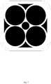
- the black area in Fig. 7 is the corresponding heating center area when heating.
- the second electromagnetic coil 2b and the third electromagnetic coil 2c there is no limitation to the specific positioning relationship between the second electromagnetic coil 2b and the third electromagnetic coil 2c.
- the third electromagnetic coil 2c surrounds the first electromagnetic coil 2a, and the second electromagnetic coil 2b is disposed within the third electromagnetic coil 2c.
- the second electromagnetic coil 2b and the third electromagnetic coil 2c are disposed concentrically. It is convenient to arrange the first electromagnetic coil 2a in an area between the second electromagnetic coil 2b and the third electromagnetic coil 2c in such arrangement.
- the third coil 2c may be arranged in an annular shape and concentric to the second electromagnetic coil 2b, in order to facilitate winding.
- the first electromagnetic coils 2a may be connected in series to form a first electromagnetic coil groups
- the second electromagnetic coil 2b and the third electromagnetic coil 2c may be connected in series to form a second electromagnetic coil group.
- controlling can be realized in areas by switching between the first electromagnetic coil group formed by the first electromagnetic coils 2a and the second electromagnetic coil group formed by the second electromagnetic coil 2b and the third electromagnetic coil 2c.
- the electromagnetic heating device 101 includes a cooking base (not shown). And it is a heating base in the case of an electromagnetic oven.
- a working surface is formed on the cooking base for placing and heating the pot 102, and the distance between the upper ends of the electromagnetic coils 2 and the working surface is defined as d. That is, when the electromagnetic coils 2 are distributed in a same level (for example, the coil disks are arranged in a flat shape), d is the distance between the upper end surface of any of the electromagnetic coils 2 and the working surface.
- the working surface is usually also an uneven surface.
- d is the distance between each point of the upper end surface of the electromagnetic coil 2 and the right point on the working surface in the vertical direction.
- multiple heating areas will be formed by the first electromagnetic coils 2a and problems are solved regarding heating over-concentration and insufficient effective heating area in the related art.
- a poor magnetic field area will be formed in the exterior area of the first electromagnetic coils 2a.
- a poor heating area will be formed.
- the arrangement of the first electromagnetic coils 2a decreases the coupling coefficient between the magnetic field generated by the first electromagnetic coils 2a and the pot 102, resulting in unsatisfactory power. Therefore, in order to improve the coupling coefficient (inductance and resistance) between the magnetic field generated by the first electromagnetic coils 2a and the cooker 102, d is defined as 5mm ⁇ d ⁇ 8mm.
- Fig. 6 and 7 are referred to in a combined manner, the embodiment provided in Figs. 6 and 7 will be fully described below, specifically as follows.
- the electromagnetic coils 2 are arranged on the coil disk 1.
- the electromagnetic coils 2 include multiple first electromagnetic coils 2a which are distributed and spaced apart on the coil disk 1 to correspondingly form multiple independent winding areas and further correspondingly form multiple magnetic field centers.
- the electromagnetic coils 2 further include the second electromagnetic coil 2b and the third electromagnetic coil 2c.
- a first electromagnetic coils 2a are distributed and spaced on the coil disk 1 to correspondingly form multiple magnetic field centers. Multiple heating centers are thus formed during heating process.
- the problem can be solved of heating over-concentration in the related art.
- the first electromagnetic coils 2a are distributed and spaced to form multiple heating centers with various respective centers.
- the heating area is larger compared to the related art.
- multiple heating centers are distributed in a wider area, and the effective heating area can be increased to improve an insufficient effective heating area in the related art.
- the second electromagnetic coil 2b and/or the third electromagnetic coil 2c are arranged.
- the second electromagnetic coil 2b can enhance the magnetic field strength of the spaced area between the first electromagnetic coils 2a.
- the third electromagnetic coil 2c can enhance the magnetic field strength of at least two of the first electromagnetic coils 2a on their outer surroundings.
- the coupling coefficient between the magnetic field generated by the electromagnetic coils 2 and the pot can be increased to improve the heating power.
- the third electromagnetic coil 2c and the second electromagnetic coil 2b are arranged concentrically.
- the second electromagnetic coil 2b is arranged in an annular shape
- the third electromagnetic coil 2c is arranged in a rectangular shape with arc-like transition corners.
- the circle where the arc segments of the second electromagnetic coil 2b are and the third electromagnetic coil 2c can be arranged concentrically to facilitate winding.
Landscapes
- Physics & Mathematics (AREA)
- Electromagnetism (AREA)
- Induction Heating Cooking Devices (AREA)
Abstract
Description
- The present disclosure relates to the technical field of cooking appliances, in particular to an electromagnetic heating device and a cooking appliance.
- In household electrical appliances, the heating appliance is typically circular, and magnetic field heating coil widely used is almost circular. Because the heating coil is wound in circle, the cooking appliance typically has a circular heating area. However, due to eddy-current concentration of the magnetic field on the appliance, the heating area cannot cover the projection area of the appliance corresponding to the coil, and the heating area is smaller than the effective area of the coil surface. This may result in a poor cooking experience, heating over-concentration and other problems.
- The present disclosure is to provide an electromagnetic heating device and a cooking appliance, aiming at improving the insufficient effective heating area and heating over-concentration in the related technology.
- In order to achieve the above object, the present disclosure provides an electromagnetic heating device, which includes:
- a coil disk; and,
- electromagnetic coils arranged on the coil disk, wherein the electromagnetic coils comprise first electromagnetic coils distributed and spaced on the coil disk;
- a second electromagnetic coil at an interval between the first electromagnetic coils; and/or,
- a third electromagnetic coil sourrounding at least two of the first electromagnetic coils.
- In some of the embodiments, an outer diameter of the second electromagnetic coil is smaller than an outer diameter of one of the first electromagnetic coils.
- In some of the embodiments, the first electromagnetic coils are arranged in rows and columns.
- In some of the embodiments, the second electromagnetic coil is arranged between the first electromagnetic coils of two adjacent columns and two adjacent rows.
- In some of the embodiments, the electromagnetic coils include the second electromagnetic coil and the third electromagnetic coil, and the third electromagnetic coil and the second electromagnetic coil are concentric.
- In some of the embodiments, the third electromagnetic coil includes a convex portion protruding inward, and the convex portion is extending into an outer part of a space between two adjacent first electromagnetic coils.
- In some of the embodiments, the third electromagnetic coil surrounds the first electromagnetic coils.
- In some of the embodiments, the electromagnetic coil includes two or more third electromagnetic coils.
- In some of the embodiments, the third electromagnetic coils are arranged in an inner circle and in an outer circle, forming an annular area between two adjacent third electromagnetic coils, and the first electromagnetic coils are arranged in the annular area, and at least two first electromagnetic coils are surrounded by the third electromagnetic coil located in an innermost circle.
- In some of the embodiments, the third electromagnetic coil is arranged in square; or,
- the third electromagnetic coil is arranged in square with an arc-like transition at corner; or,
the third electromagnetic coil is arranged in circle. - In some of the embodiments, the third electromagnetic coil and the second electromagnetic coil are concentric.
- In some of the embodiments, winding directions of the electromagnetic coils are the same, so as to allow the electromagnetic coils to generate magnetic fields in a same direction.
- In some of the embodiments, the electromagnetic coils are connected in series.
- In some of the embodiments, the electromagnetic coils are divided into at least two independently controlled electromagnetic coil groups.
- In some of the embodiments, the electromagnetic coils further include the second electromagnetic coil and the third electromagnetic coil;
the first electromagnetic coils are connected in series to form a first electromagnetic coil group, and the second electromagnetic coil and the third electromagnetic coil are connected in series to form a second electromagnetic coil group. - In some of the embodiments, the electromagnetic heating device includes a cooking base provided with a working surface for placing and heating a pot;
a distance between an upper end of the electromagnetic coils and the working surface is d, and 5 mm ≤ d ≤ 8 mm. - In some of the embodiments, the coil disk is concave; or,
the coil disk is flat. - The present disclosure further provides a cooking appliance, which includes an electromagnetic heating device including:
- a coil disk; and,
- electromagnetic coils arranged on the coil disk, wherein the electromagnetic coils comprise first electromagnetic coils distributed and spaced on the coil disk;
- a second electromagnetic coil at an interval between the first electromagnetic coils; and/or,
- a third electromagnetic coil surrounding at least two of the first electromagnetic coils.
- In the technical solution of the present disclosure, first electromagnetic coils are distributed and spaced on the coil disk to correspondingly form magnetic field centers. Such arrangement may overcome the problem of heating concentration in the related art. And compared with a large heating area in the related art, the first electromagnetic coils are distributed and spaced to form heating small centers taking each as a center, resulting in wider heating area and thus a larger effective heating area to improve the insufficient effective heating area in the related art. Further, a second electromagnetic coil and/or a third electromagnetic coil are arranged. The second electromagnetic coil is arranged in a spaced area between the first electromagnetic coils, and the third electromagnetic coil is arranged around at least two of the first electromagnetic coils. The second electromagnetic coil can enhance the magnetic field strength of the spaced area between the first electromagnetic coils, and the third electromagnetic coil can enhance the magnetic field strength of the first electromagnetic coil wounded around its outside. The coupling coefficient between the magnetic field generated by the electromagnetic coils and the cooking appliance is increased through the second electromagnetic coil and/or the third electromagnetic coil to improve heating power.
- In order to explain the embodiment of the present application or the technical solution of the prior art more clearly, the following will briefly introduce the drawings necessary in the description of the embodiments or the prior art. Obviously, the drawings in the following description are only some embodiments of the present application. For those ordinary skill in the art, other drawings can be obtained according to the structure shown in these drawings without any creative effort.
-
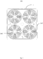
Fig. 1 is a schematic plan view of the electromagnetic heating device according to the present disclosure when only the first electromagnetic coil is provided; -
Fig. 2 is a schematic diagram of the thermal field distribution when the electromagnetic heating device ofFig. 1 is heated; -
Fig. 3 is a schematic plan view of the cooking appliance according to a first embodiment of the present disclosure, in which the electromagnetic heating device in this figure is the electromagnetic heating device of the first embodiment; -
Fig. 4 is a schematic plan view of the electromagnetic heating device inFig. 3 ; -
Fig. 5 is a schematic plan view of the electromagnetic heating device inFig. 3 according to a second embodiment of the present disclosure; -
Fig. 6 is a schematic plan view of the electromagnetic heating device inFig. 3 according to a third embodiment of the present disclosure; -
Fig. 7 is a schematic diagram of the thermal field distribution when the electromagnetic heating device ofFig. 6 is heated; -
Fig. 8 is a schematic plan view of the electromagnetic heating device inFig. 3 according to a fourth embodiment of the present disclosure; -
Fig. 9 is a schematic plan view of the electromagnetic heating device inFig. 3 according to a fifth embodiment of the present disclosure. - As following, the technical solution in the embodiments of the present disclosure will be described clearly and completely with reference to the drawings in the embodiment of the present application. Obviously, the described embodiment is only a part of the embodiment of the present disclosure, not all of the embodiments. Based on the embodiments in the present application, all other embodiments obtained by those skilled in the art without making creative effort, shall fall within the protection scope of the present application.
- It should be appreciated that if directional indications (such as up, down, left, right, front, back, etc.) are involved in the embodiments of the present application, the directional indications are only used to explain the relative positional relationship and movement between the components in a certain posture (as shown in the drawings), and if the specific posture changes, the directional indications will change accordingly.
- In addition, if there are descriptions of "first" and "second" in the embodiments of this disclosure, the descriptions of "first" and "second" are used for descriptive purposes only and cannot be understood as indicating or implying their relative importance or implicitly indicating the number of indicated technical features. Thus, features defining "first" and "second" may explicitly or implicitly include at least one of the features. In addition, the meaning of " and/or" appearing in the full text is to include three parallel schemes, taking " a and/or b" as some embodiments, including solution of a or b, or solution that both a and b satisfy at the same time. In addition, the technical solutions between the various embodiments may be combined with each other, but must be based on what one of ordinary skill in the art can achieve. When the combination of technical solutions is contradictory or impossible to achieve, it should be considered that the combination of such technical solutions does not exist and is not within the protection scope required by the present disclosure.
- The present disclosure provides a cooking appliance, as shown in
Fig. 3 . Thecooking appliance 100 includes anelectromagnetic heating device 101 and apot 102. Thecooking appliance 100 can be but not limited to one of an induction cooker, an electric cooker, an electric pressure cooker and a cooking machine.Figs. 4 to 9 are the electromagnetic heating device according to embodiments provided by the present disclosure. The electromagnetic heating device provided by the present disclosure will be described in detail below with reference to the attached drawings. - Referring to
Fig. 4 , the present disclosure provides anelectromagnetic heating device 101, which includes acoil disk 1 andelectromagnetic coils 2. - The shape or structure of the
coil disk 1 should not be limited. For example, thecoil disk 1 may be arranged in a concave shape, as shown inFigs. 4 to 9 . Thecoil disk 1 is generally suitable for induction cookers. - Referring to
Fig. 4 continuously, theelectromagnetic coils 2 are arranged on thecoil disk 1. Theelectromagnetic coils 2 include multiple firstelectromagnetic coils 2a which are distributed and spaced apart on thecoil disk 1 to correspondingly form multiple independent winding areas and further correspondingly form multiple magnetic field centers. - Multiple heating areas will be formed by the first
electromagnetic coils 2a, improving the heating over-concentration and insufficient effective heating area in the related art. However, as can be seen fromFigs. 1 and2 , areas (blank portions) are formed in the areas and peripheries between the firstelectromagnetic coils 2a where the magnetic field is poor. As such, poor heating areas are correspondingly formed. Further, compared to a large electromagnetic coil with a same winding range, the firstelectromagnetic coils 2a in such arrangement would decrease the coupling coefficient between the magnetic field generated by the firstelectromagnetic coils 2a and thecooker 102, resulting in a unsatisfactory heating power. For above, in the present disclosure, as shown inFigs. 4 to 9 , theelectromagnetic coils 2 further include a secondelectromagnetic coil 2b and/or a thirdelectromagnetic coil 2c. The secondelectromagnetic coil 2b is disposed in a spaced area between the firstelectromagnetic coils 2a, and the thirdelectromagnetic coil 2c surrounds at least two of the firstelectromagnetic coils 2a. - In the technical solution of the present disclosure, a first
electromagnetic coils 2a are distributed and spaced on thecoil disk 1 to correspondingly form multiple magnetic field centers. Multiple heating centers are thus formed during heating process (as shown inFig. 2 , four black areas are four heating centers). The problem can be solved of heating over-concentration in the related art. The firstelectromagnetic coils 2a are distributed and spaced to form multiple heating centers with various respective centers. The heating area is larger compared to the related art. According to the technical solution of the present disclosure, multiple heating centers are distributed in a wider area, and the effective heating area can be increased to improve an insufficient effective heating area in the related art. Furthermore, as can be seen fromFig. 7 , the secondelectromagnetic coil 2b and/or the thirdelectromagnetic coil 2c are arranged. The secondelectromagnetic coil 2b can enhance the magnetic field strength of the spaced area between the firstelectromagnetic coils 2a. The thirdelectromagnetic coil 2c can enhance the magnetic field strength of at least two of the firstelectromagnetic coils 2a on their outer surroundings. The coupling coefficient between the magnetic field generated by theelectromagnetic coils 2 and the pot can be increased to improve the heating power. - The first
electromagnetic coils 2a are distributed on thecoil disk 1, and the specific distribution is not limited herein. Refer toFigs. 4 to 7 , in these embodiments, the firstelectromagnetic coils 2a are distributed in rows and columns. In some other embodiments, as shown inFig. 8 , the firstelectromagnetic coils 2a may be distributed circumferentially in annular shape. Obviously, the distribution of the firstelectromagnetic coils 2a depends on the requirements of the effective heating area. For example, if the effective heating area is circular, it is preferable that the firstelectromagnetic coils 2a are distributed annularly. While with respect to the effective heating area which is square, etc. correspondingly, the firstelectromagnetic coils 2a are arranged in a square. A specific example is provided in a matrix arrangement, specifically in a matrix arrangement of 2rows ∗ 2 columns as shown inFigs. 4 to 7 . - For above, it can be seen that the
electromagnetic coils 2 further include the secondelectromagnetic coil 2b and/or the thirdelectromagnetic coil 2c. Correspondingly, there are three specific scenarios. As shown inFigs. 3 and4 , theelectromagnetic coils 2 include the firstelectromagnetic coil 2a and the thirdelectromagnetic coil 2c; as shown inFig. 5 , theelectromagnetic coils 2 include the firstelectromagnetic coil 2a and the secondelectromagnetic coil 2b; and as shown inFig. 6 , theelectromagnetic coils 2 include the firstelectromagnetic coil 2a, the secondelectromagnetic coil 2b, and the thirdelectromagnetic coil 2c. All these variations would be described below with reference to the attached drawings respectively. - In the present disclosure, multiple heating areas will be formed by the first
electromagnetic coils 2a and problems are solved regarding heating over-concentration and insufficient effective heating area in the related art. Obviously, a poor magnetic field area will be formed in the area between the firstelectromagnetic coils 2a. Correspondingly, a poor heating area will be formed. And compared to a large electromagnetic coil in the same winding range, the arrangement of the firstelectromagnetic coils 2a decreases the coupling coefficient between the magnetic field generated by the firstelectromagnetic coils 2a and thepot 102, resulting in unsatisfactory power. As such, in some embodiment of the present invention, as shown inFig. 5 , theelectromagnetic coils 2 further include the secondelectromagnetic coils 2b, which are distributed in the spaced area between the firstelectromagnetic coils 2a. The secondelectromagnetic coil 2b can compensate the magnetic field in the spaced area to further improve the heating uniformity. Furthermore, the coupling coefficient between the magnetic field generated by theelectromagnetic coils 2 and thepot 102 can be increased to improve the heating power. - Since the second
electromagnetic coil 2b is arranged in the spaced area of the firstelectromagnetic coils 2a, the firstelectromagnetic coils 2a are distributed at regular space intervals, and the spaced area formed between the firstelectromagnetic coils 2a is relatively small. Therefore, the outer diameter of the secondelectromagnetic coil 2b is usually smaller than the outer diameter of the firstelectromagnetic coil 2a, so that the arrangement of the secondelectromagnetic coil 2b in the space area of the firstelectromagnetic coils 2a is facilitated. It should be appreciated that theelectromagnetic coil 2 is not limited to being circular, that is, the firstelectromagnetic coil 2a and the secondelectromagnetic coil 2b are not limited to being circular. As such, the outer diameters of the secondelectromagnetic coil 2b and the firstelectromagnetic coil 2a, if the secondelectromagnetic coil 2b and the firstelectromagnetic coil 2a are circular, are the corresponding diameter; and if they are non-circular, the outer diameter is considered as the diameter of the circumscribed circle of the firstelectromagnetic coils 2a or the secondelectromagnetic coil 2b. - Further, as shown in
Fig. 5 , the firstelectromagnetic coils 2a are distributed in rows and columns, and the secondelectromagnetic coils 2b are disposed between the firstelectromagnetic coils 2a of two adjacent columns and two adjacent rows. Obviously, the arrangement is not limited to above description. If the firstelectromagnetic coils 2a are annularly distributed, the secondelectromagnetic coils 2b may be distributed inside the annular area defined by the firstelectromagnetic coils 2a, as shown inFig. 8 . - In the present disclosure, multiple heating areas will be formed by the first
electromagnetic coils 2a and problems are solved regarding heating over-concentration and insufficient effective heating area in the related art. Obviously, a poor magnetic field area will be formed in the exterior area of the firstelectromagnetic coils 2a. Correspondingly, a poor heating area will be formed. And compared to a large electromagnetic coil in the same winding range, the arrangement of the firstelectromagnetic coils 2a decreases the coupling coefficient between the magnetic field generated by the firstelectromagnetic coils 2a and thepot 102, resulting in unsatisfactory power. As such, in some embodiment of the present invention, as shown inFig. 5 , theelectromagnetic coils 2 further include the thirdelectromagnetic coils 2c, configured to improve the magnetic field distributed at the exterior surroundings of at least two of the firstelectromagnetic coils 2a. And the heating uniformity is improved. Furthermore, the coupling coefficient between the magnetic field generated by theelectromagnetic coils 2 and thepot 102 can be increased to improve the heating power. - The third
electromagnetic coil 2c is sourrounding at least two of the firstelectromagnetic coils 2a, and the number of the thirdelectromagnetic coils 2c and the number of the firstelectromagnetic coils 2a are not limited. - For example, as shown in
Fig. 4 , one thirdelectromagnetic coil 2c is provided sourrounding all of the firstelectromagnetic coils 2a. - Alternatively, as shown in
Fig. 8 , two or more of the thirdelectromagnetic coils 2c may be provided. As such, the firstelectromagnetic coils 2a in different areas can be respectively wound around, and the arrangement density of theelectromagnetic coils 2 can be further improved to increase the heating power. Specifically, as shown inFig. 8 , multiple thirdelectromagnetic coils 2c are arranged in inner and outer rings to form an annular area between two adjacent thirdelectromagnetic coils 2c. The firstelectromagnetic coils 2a is provided in the annular area, and at least two firstelectromagnetic coils 2a are arranged in the innermost thirdelectromagnetic coil 2c. - The shape of the third
electromagnetic coil 2c is not limited, which may depend on the actual distribution area of the firstelectromagnetic coils 2a, the actual heating area, or the actual heating effect. For example, the thirdelectromagnetic coil 2c may be in square, or in circle; or, as shown inFig. 3 , thethird coil 2c may be arranged in square with an arc-like transition at corner. - Moreover, in some embodiments, considering the actual magnetic field distribution, the third
electromagnetic coil 2c may be specially arranged. As shown inFig. 9 , the thirdelectromagnetic coil 2c is formed withconvex portions 21c protruding inward, and theconvex portions 21c is extended into the outer part of the space between two adjacent firstelectromagnetic coils 2a, compensating the shortage of the magnetic field in the outer gap and further improving the heating uniformity. - The surrounding direction of the
electromagnetic coils 2 can be clockwise or counterclockwise. Specifically, in the embodiment of the present disclosure, the winding directions of theelectromagnetic coils 2 are all the same, so that the magnetic fields generated by theelectromagnetic coils 2 have the same direction, and magnetic field cancellation due to different winding directions is avoided. - The connection between the
electromagnetic coils 2 can be in parallel, in series, or combined parallel and series. In some embodiments of the present disclosure, theelectromagnetic coils 2 are divided into at least two electromagnetic coil groups which are independent controlled. Thus theelectromagnetic coils 2 are arranged in groups, and the power supply and power loss of each group are respectively controlled. Whether to heat or not regarding each group of electromagnetic coil groups is controlled. As such, the boiling can be realized by switching the electromagnetic coil groups of different groups to heat, improving the cooking effect. - According to the technical solution disclosed above, the
electromagnetic coils 2 may include a secondelectromagnetic coil 2b and a thirdelectromagnetic coil 2c simultaneously. As shown inFig. 6 , similarly, the secondelectromagnetic coil 2b is distributed in the space area between the firstelectromagnetic coils 2a. And the thirdelectromagnetic coil 2c surrounds the firstelectromagnetic coils 2a. In the present embodiment, by providing the secondelectromagnetic coil 2b in the space area between the firstelectromagnetic coils 2a and by providing the thirdelectromagnetic coil 2c at the exterior periphery of the firstelectromagnetic coils 2a, the magnetic field strength of the gap area and the outer surroundings between the firstelectromagnetic coils 2a can be enhanced. The coupling coefficient between the magnetic field generated by theelectromagnetic coils 2 and thepot 102 can be increased to improve the heating power. Specifically,Fig. 7 is referred to. The black area inFig. 7 is the corresponding heating center area when heating. - There is no limitation to the specific positioning relationship between the second
electromagnetic coil 2b and the thirdelectromagnetic coil 2c. In general, since the thirdelectromagnetic coil 2c surrounds the firstelectromagnetic coil 2a, and the secondelectromagnetic coil 2b is disposed within the thirdelectromagnetic coil 2c. Preferably, the secondelectromagnetic coil 2b and the thirdelectromagnetic coil 2c are disposed concentrically. It is convenient to arrange the firstelectromagnetic coil 2a in an area between the secondelectromagnetic coil 2b and the thirdelectromagnetic coil 2c in such arrangement. Furthermore, thethird coil 2c may be arranged in an annular shape and concentric to the secondelectromagnetic coil 2b, in order to facilitate winding. - Further, in the embodiment provided in
Fig. 6 , the firstelectromagnetic coils 2a may be connected in series to form a first electromagnetic coil groups, and the secondelectromagnetic coil 2b and the thirdelectromagnetic coil 2c may be connected in series to form a second electromagnetic coil group. As such, controlling can be realized in areas by switching between the first electromagnetic coil group formed by the firstelectromagnetic coils 2a and the second electromagnetic coil group formed by the secondelectromagnetic coil 2b and the thirdelectromagnetic coil 2c. - The
electromagnetic heating device 101 includes a cooking base (not shown). And it is a heating base in the case of an electromagnetic oven. A working surface is formed on the cooking base for placing and heating thepot 102, and the distance between the upper ends of theelectromagnetic coils 2 and the working surface is defined as d. That is, when theelectromagnetic coils 2 are distributed in a same level (for example, the coil disks are arranged in a flat shape), d is the distance between the upper end surface of any of theelectromagnetic coils 2 and the working surface. When theelectromagnetic coils 2 are distributed in different levels (the coil disks are arranged in a concave manner and theelectromagnetic coils 2 are distributed in different surfaces), the working surface is usually also an uneven surface. As such, d is the distance between each point of the upper end surface of theelectromagnetic coil 2 and the right point on the working surface in the vertical direction. In the present disclosure, multiple heating areas will be formed by the firstelectromagnetic coils 2a and problems are solved regarding heating over-concentration and insufficient effective heating area in the related art. Obviously, a poor magnetic field area will be formed in the exterior area of the firstelectromagnetic coils 2a. Correspondingly, a poor heating area will be formed. And compared to a large electromagnetic coil in the same winding range, the arrangement of the firstelectromagnetic coils 2a decreases the coupling coefficient between the magnetic field generated by the firstelectromagnetic coils 2a and thepot 102, resulting in unsatisfactory power. Therefore, in order to improve the coupling coefficient (inductance and resistance) between the magnetic field generated by the firstelectromagnetic coils 2a and thecooker 102, d is defined as 5mm≤d≤8mm. -
Fig. 6 and7 are referred to in a combined manner, the embodiment provided inFigs. 6 and7 will be fully described below, specifically as follows. - The
electromagnetic coils 2 are arranged on thecoil disk 1. Theelectromagnetic coils 2 include multiple firstelectromagnetic coils 2a which are distributed and spaced apart on thecoil disk 1 to correspondingly form multiple independent winding areas and further correspondingly form multiple magnetic field centers. Theelectromagnetic coils 2 further include the secondelectromagnetic coil 2b and the thirdelectromagnetic coil 2c. - In the technical solution of the present disclosure, a first
electromagnetic coils 2a are distributed and spaced on thecoil disk 1 to correspondingly form multiple magnetic field centers. Multiple heating centers are thus formed during heating process. The problem can be solved of heating over-concentration in the related art. The firstelectromagnetic coils 2a are distributed and spaced to form multiple heating centers with various respective centers. The heating area is larger compared to the related art. According to the technical solution of the present disclosure, multiple heating centers are distributed in a wider area, and the effective heating area can be increased to improve an insufficient effective heating area in the related art. Furthermore, as can be seen fromFig. 7 , the secondelectromagnetic coil 2b and/or the thirdelectromagnetic coil 2c are arranged. The secondelectromagnetic coil 2b can enhance the magnetic field strength of the spaced area between the firstelectromagnetic coils 2a. The thirdelectromagnetic coil 2c can enhance the magnetic field strength of at least two of the firstelectromagnetic coils 2a on their outer surroundings. The coupling coefficient between the magnetic field generated by theelectromagnetic coils 2 and the pot can be increased to improve the heating power. - In the embodiment provided in
Fig. 6 , the thirdelectromagnetic coil 2c and the secondelectromagnetic coil 2b are arranged concentrically. The secondelectromagnetic coil 2b is arranged in an annular shape, and the thirdelectromagnetic coil 2c is arranged in a rectangular shape with arc-like transition corners. Thus, the circle where the arc segments of the secondelectromagnetic coil 2b are and the thirdelectromagnetic coil 2c can be arranged concentrically to facilitate winding. - The above is only the optional embodiment of the present disclosure and is not therefore constitute a limitation to the present disclosure. Any equivalent structure modification perceived by using the contents of the present specification and drawings, or directly or indirectly applied in other related technical fields, shall be included in the protection scope of the present disclosure.
| Reference Numeral | Name | Reference | Name | |
| 100 | | 2b | Second | |
| 101 | | 2c | Third | |
| 1 | | 21c | Convex | |
| 2 | | 102 | | |
| 2a | First electromagnetic coil |
Claims (14)
and/or, wherein the third electromagnetic coil (2c) surrounds the first electromagnetic coils (2a).
the third electromagnetic coil (2c) is arranged in a square with an arc-like transition at a corner; or,
the third electromagnetic coil (2c) is arranged in a circle.
the first electromagnetic coils (2a) are connected in series to form a first electromagnetic coil group; the second electromagnetic coil (2b) and the third electromagnetic coil (2c) are connected in series to form a second electromagnetic coil group.
a distance between an upper end of the electromagnetic coils (2) and the working surface is d, wherein 5 mm ≤ d ≤ 8 mm;
and/or, wherein:
Applications Claiming Priority (2)
| Application Number | Priority Date | Filing Date | Title |
|---|---|---|---|
| CN201921589453 | 2019-09-23 | ||
| CN201921815716.1U CN210928041U (en) | 2019-09-23 | 2019-10-25 | Electromagnetic heating device and cooking utensil |
Publications (2)
| Publication Number | Publication Date |
|---|---|
| EP3796756A1 true EP3796756A1 (en) | 2021-03-24 |
| EP3796756B1 EP3796756B1 (en) | 2024-01-10 |
Family
ID=71352142
Family Applications (1)
| Application Number | Title | Priority Date | Filing Date |
|---|---|---|---|
| EP20168309.1A Active EP3796756B1 (en) | 2019-09-23 | 2020-04-06 | Electromagnetic heating device and cooking appliance |
Country Status (2)
| Country | Link |
|---|---|
| EP (1) | EP3796756B1 (en) |
| CN (1) | CN210928041U (en) |
Citations (4)
| Publication number | Priority date | Publication date | Assignee | Title |
|---|---|---|---|---|
| JP2009016251A (en) * | 2007-07-06 | 2009-01-22 | Fujimak Corp | Electromagnetic cooker |
| JP2013054951A (en) * | 2011-09-05 | 2013-03-21 | Mitsubishi Electric Corp | Induction heating cooker |
| WO2018106013A1 (en) * | 2016-12-08 | 2018-06-14 | Samsung Electronics Co., Ltd. | Cooking apparatus |
| CN207638927U (en) * | 2017-12-29 | 2018-07-20 | 浙江绍兴苏泊尔生活电器有限公司 | Coil panel and induction cooker |
-
2019
- 2019-10-25 CN CN201921815716.1U patent/CN210928041U/en active Active
-
2020
- 2020-04-06 EP EP20168309.1A patent/EP3796756B1/en active Active
Patent Citations (4)
| Publication number | Priority date | Publication date | Assignee | Title |
|---|---|---|---|---|
| JP2009016251A (en) * | 2007-07-06 | 2009-01-22 | Fujimak Corp | Electromagnetic cooker |
| JP2013054951A (en) * | 2011-09-05 | 2013-03-21 | Mitsubishi Electric Corp | Induction heating cooker |
| WO2018106013A1 (en) * | 2016-12-08 | 2018-06-14 | Samsung Electronics Co., Ltd. | Cooking apparatus |
| CN207638927U (en) * | 2017-12-29 | 2018-07-20 | 浙江绍兴苏泊尔生活电器有限公司 | Coil panel and induction cooker |
Also Published As
| Publication number | Publication date |
|---|---|
| CN210928041U (en) | 2020-07-03 |
| EP3796756B1 (en) | 2024-01-10 |
Similar Documents
| Publication | Publication Date | Title |
|---|---|---|
| EP2207401B1 (en) | Cooking apparatus and heating device including working coils thereof | |
| AU2015309254B2 (en) | Induction heating arrangement, method for operating an induction heating arrangement and induction hob | |
| US11219101B2 (en) | Induction cooking appliance having multiple heating coils | |
| CN205196001U (en) | Coil plate and induction cooker | |
| EP3796756B1 (en) | Electromagnetic heating device and cooking appliance | |
| WO2026067728A1 (en) | Coil disk assembly and electromagnetic heating device | |
| CN118055533A (en) | Electromagnetic heating coil assembly and cooking utensil | |
| CN207219080U (en) | The electromagnetic wire coil and electromagnetic cooking appliance of a kind of electromagnetic cooking appliance | |
| CN209419905U (en) | Coil panel seat, coil panel and electromagnetic cooking appliance | |
| CN201910943U (en) | Heating coil panel | |
| JPH1140335A (en) | Induction heating cooker | |
| CN204518114U (en) | Heating coil panel and induction cooker | |
| JP2005026204A (en) | Induction heating cooker | |
| CN222706658U (en) | Mounting bracket, coil pan assembly and cooking utensil | |
| CN206472337U (en) | Coil panel component and electromagnetic cooking appliance | |
| CN108243522B (en) | Coil panel assembly and electromagnetic cooking utensil | |
| CN222706657U (en) | Heating device and cooking utensil | |
| CN222928531U (en) | Coil panel assembly and electromagnetic heating device | |
| JPS6134716Y2 (en) | ||
| CN209419910U (en) | Coil panel and electromagnetic heating cooker | |
| CN119815612B (en) | Square coil disc | |
| CN222602615U (en) | Coil pans and cooking equipment | |
| WO2017093174A1 (en) | An inductive coil unit | |
| CN106358329B (en) | Coil panel assembly and electromagnetic heating cooking device | |
| JP2010010038A (en) | Induction heating cooker |
Legal Events
| Date | Code | Title | Description |
|---|---|---|---|
| PUAI | Public reference made under article 153(3) epc to a published international application that has entered the european phase |
Free format text: ORIGINAL CODE: 0009012 |
|
| STAA | Information on the status of an ep patent application or granted ep patent |
Free format text: STATUS: THE APPLICATION HAS BEEN PUBLISHED |
|
| AK | Designated contracting states |
Kind code of ref document: A1 Designated state(s): AL AT BE BG CH CY CZ DE DK EE ES FI FR GB GR HR HU IE IS IT LI LT LU LV MC MK MT NL NO PL PT RO RS SE SI SK SM TR |
|
| AX | Request for extension of the european patent |
Extension state: BA ME |
|
| STAA | Information on the status of an ep patent application or granted ep patent |
Free format text: STATUS: REQUEST FOR EXAMINATION WAS MADE |
|
| 17P | Request for examination filed |
Effective date: 20210922 |
|
| RBV | Designated contracting states (corrected) |
Designated state(s): AL AT BE BG CH CY CZ DE DK EE ES FI FR GB GR HR HU IE IS IT LI LT LU LV MC MK MT NL NO PL PT RO RS SE SI SK SM TR |
|
| GRAP | Despatch of communication of intention to grant a patent |
Free format text: ORIGINAL CODE: EPIDOSNIGR1 |
|
| STAA | Information on the status of an ep patent application or granted ep patent |
Free format text: STATUS: GRANT OF PATENT IS INTENDED |
|
| GRAS | Grant fee paid |
Free format text: ORIGINAL CODE: EPIDOSNIGR3 |
|
| GRAA | (expected) grant |
Free format text: ORIGINAL CODE: 0009210 |
|
| STAA | Information on the status of an ep patent application or granted ep patent |
Free format text: STATUS: THE PATENT HAS BEEN GRANTED |
|
| INTG | Intention to grant announced |
Effective date: 20231114 |
|
| AK | Designated contracting states |
Kind code of ref document: B1 Designated state(s): AL AT BE BG CH CY CZ DE DK EE ES FI FR GB GR HR HU IE IS IT LI LT LU LV MC MK MT NL NO PL PT RO RS SE SI SK SM TR |
|
| REG | Reference to a national code |
Ref country code: GB Ref legal event code: FG4D |
|
| REG | Reference to a national code |
Ref country code: CH Ref legal event code: EP |
|
| REG | Reference to a national code |
Ref country code: DE Ref legal event code: R096 Ref document number: 602020024089 Country of ref document: DE |
|
| REG | Reference to a national code |
Ref country code: IE Ref legal event code: FG4D |
|
| REG | Reference to a national code |
Ref country code: LT Ref legal event code: MG9D |
|
| REG | Reference to a national code |
Ref country code: NL Ref legal event code: MP Effective date: 20240110 |
|
| REG | Reference to a national code |
Ref country code: AT Ref legal event code: MK05 Ref document number: 1649875 Country of ref document: AT Kind code of ref document: T Effective date: 20240110 |
|
| PG25 | Lapsed in a contracting state [announced via postgrant information from national office to epo] |
Ref country code: NL Free format text: LAPSE BECAUSE OF FAILURE TO SUBMIT A TRANSLATION OF THE DESCRIPTION OR TO PAY THE FEE WITHIN THE PRESCRIBED TIME-LIMIT Effective date: 20240110 |
|
| PG25 | Lapsed in a contracting state [announced via postgrant information from national office to epo] |
Ref country code: NL Free format text: LAPSE BECAUSE OF FAILURE TO SUBMIT A TRANSLATION OF THE DESCRIPTION OR TO PAY THE FEE WITHIN THE PRESCRIBED TIME-LIMIT Effective date: 20240110 |
|
| PG25 | Lapsed in a contracting state [announced via postgrant information from national office to epo] |
Ref country code: IS Free format text: LAPSE BECAUSE OF FAILURE TO SUBMIT A TRANSLATION OF THE DESCRIPTION OR TO PAY THE FEE WITHIN THE PRESCRIBED TIME-LIMIT Effective date: 20240510 |
|
| PG25 | Lapsed in a contracting state [announced via postgrant information from national office to epo] |
Ref country code: LT Free format text: LAPSE BECAUSE OF FAILURE TO SUBMIT A TRANSLATION OF THE DESCRIPTION OR TO PAY THE FEE WITHIN THE PRESCRIBED TIME-LIMIT Effective date: 20240110 |
|
| PG25 | Lapsed in a contracting state [announced via postgrant information from national office to epo] |
Ref country code: GR Free format text: LAPSE BECAUSE OF FAILURE TO SUBMIT A TRANSLATION OF THE DESCRIPTION OR TO PAY THE FEE WITHIN THE PRESCRIBED TIME-LIMIT Effective date: 20240411 |
|
| PG25 | Lapsed in a contracting state [announced via postgrant information from national office to epo] |
Ref country code: RS Free format text: LAPSE BECAUSE OF FAILURE TO SUBMIT A TRANSLATION OF THE DESCRIPTION OR TO PAY THE FEE WITHIN THE PRESCRIBED TIME-LIMIT Effective date: 20240410 Ref country code: HR Free format text: LAPSE BECAUSE OF FAILURE TO SUBMIT A TRANSLATION OF THE DESCRIPTION OR TO PAY THE FEE WITHIN THE PRESCRIBED TIME-LIMIT Effective date: 20240110 |
|
| PG25 | Lapsed in a contracting state [announced via postgrant information from national office to epo] |
Ref country code: ES Free format text: LAPSE BECAUSE OF FAILURE TO SUBMIT A TRANSLATION OF THE DESCRIPTION OR TO PAY THE FEE WITHIN THE PRESCRIBED TIME-LIMIT Effective date: 20240110 |
|
| PG25 | Lapsed in a contracting state [announced via postgrant information from national office to epo] |
Ref country code: AT Free format text: LAPSE BECAUSE OF FAILURE TO SUBMIT A TRANSLATION OF THE DESCRIPTION OR TO PAY THE FEE WITHIN THE PRESCRIBED TIME-LIMIT Effective date: 20240110 |
|
| PG25 | Lapsed in a contracting state [announced via postgrant information from national office to epo] |
Ref country code: RS Free format text: LAPSE BECAUSE OF FAILURE TO SUBMIT A TRANSLATION OF THE DESCRIPTION OR TO PAY THE FEE WITHIN THE PRESCRIBED TIME-LIMIT Effective date: 20240410 Ref country code: NO Free format text: LAPSE BECAUSE OF FAILURE TO SUBMIT A TRANSLATION OF THE DESCRIPTION OR TO PAY THE FEE WITHIN THE PRESCRIBED TIME-LIMIT Effective date: 20240410 Ref country code: LT Free format text: LAPSE BECAUSE OF FAILURE TO SUBMIT A TRANSLATION OF THE DESCRIPTION OR TO PAY THE FEE WITHIN THE PRESCRIBED TIME-LIMIT Effective date: 20240110 Ref country code: IS Free format text: LAPSE BECAUSE OF FAILURE TO SUBMIT A TRANSLATION OF THE DESCRIPTION OR TO PAY THE FEE WITHIN THE PRESCRIBED TIME-LIMIT Effective date: 20240510 Ref country code: HR Free format text: LAPSE BECAUSE OF FAILURE TO SUBMIT A TRANSLATION OF THE DESCRIPTION OR TO PAY THE FEE WITHIN THE PRESCRIBED TIME-LIMIT Effective date: 20240110 Ref country code: GR Free format text: LAPSE BECAUSE OF FAILURE TO SUBMIT A TRANSLATION OF THE DESCRIPTION OR TO PAY THE FEE WITHIN THE PRESCRIBED TIME-LIMIT Effective date: 20240411 Ref country code: ES Free format text: LAPSE BECAUSE OF FAILURE TO SUBMIT A TRANSLATION OF THE DESCRIPTION OR TO PAY THE FEE WITHIN THE PRESCRIBED TIME-LIMIT Effective date: 20240110 Ref country code: BG Free format text: LAPSE BECAUSE OF FAILURE TO SUBMIT A TRANSLATION OF THE DESCRIPTION OR TO PAY THE FEE WITHIN THE PRESCRIBED TIME-LIMIT Effective date: 20240110 Ref country code: AT Free format text: LAPSE BECAUSE OF FAILURE TO SUBMIT A TRANSLATION OF THE DESCRIPTION OR TO PAY THE FEE WITHIN THE PRESCRIBED TIME-LIMIT Effective date: 20240110 |
|
| PG25 | Lapsed in a contracting state [announced via postgrant information from national office to epo] |
Ref country code: PL Free format text: LAPSE BECAUSE OF FAILURE TO SUBMIT A TRANSLATION OF THE DESCRIPTION OR TO PAY THE FEE WITHIN THE PRESCRIBED TIME-LIMIT Effective date: 20240110 Ref country code: PT Free format text: LAPSE BECAUSE OF FAILURE TO SUBMIT A TRANSLATION OF THE DESCRIPTION OR TO PAY THE FEE WITHIN THE PRESCRIBED TIME-LIMIT Effective date: 20240510 |
|
| PG25 | Lapsed in a contracting state [announced via postgrant information from national office to epo] |
Ref country code: SE Free format text: LAPSE BECAUSE OF FAILURE TO SUBMIT A TRANSLATION OF THE DESCRIPTION OR TO PAY THE FEE WITHIN THE PRESCRIBED TIME-LIMIT Effective date: 20240110 Ref country code: PT Free format text: LAPSE BECAUSE OF FAILURE TO SUBMIT A TRANSLATION OF THE DESCRIPTION OR TO PAY THE FEE WITHIN THE PRESCRIBED TIME-LIMIT Effective date: 20240510 Ref country code: PL Free format text: LAPSE BECAUSE OF FAILURE TO SUBMIT A TRANSLATION OF THE DESCRIPTION OR TO PAY THE FEE WITHIN THE PRESCRIBED TIME-LIMIT Effective date: 20240110 Ref country code: LV Free format text: LAPSE BECAUSE OF FAILURE TO SUBMIT A TRANSLATION OF THE DESCRIPTION OR TO PAY THE FEE WITHIN THE PRESCRIBED TIME-LIMIT Effective date: 20240110 |
|
| PG25 | Lapsed in a contracting state [announced via postgrant information from national office to epo] |
Ref country code: DK Free format text: LAPSE BECAUSE OF FAILURE TO SUBMIT A TRANSLATION OF THE DESCRIPTION OR TO PAY THE FEE WITHIN THE PRESCRIBED TIME-LIMIT Effective date: 20240110 |
|
| REG | Reference to a national code |
Ref country code: DE Ref legal event code: R097 Ref document number: 602020024089 Country of ref document: DE |
|
| PG25 | Lapsed in a contracting state [announced via postgrant information from national office to epo] |
Ref country code: SM Free format text: LAPSE BECAUSE OF FAILURE TO SUBMIT A TRANSLATION OF THE DESCRIPTION OR TO PAY THE FEE WITHIN THE PRESCRIBED TIME-LIMIT Effective date: 20240110 |
|
| PG25 | Lapsed in a contracting state [announced via postgrant information from national office to epo] |
Ref country code: EE Free format text: LAPSE BECAUSE OF FAILURE TO SUBMIT A TRANSLATION OF THE DESCRIPTION OR TO PAY THE FEE WITHIN THE PRESCRIBED TIME-LIMIT Effective date: 20240110 Ref country code: CZ Free format text: LAPSE BECAUSE OF FAILURE TO SUBMIT A TRANSLATION OF THE DESCRIPTION OR TO PAY THE FEE WITHIN THE PRESCRIBED TIME-LIMIT Effective date: 20240110 |
|
| PG25 | Lapsed in a contracting state [announced via postgrant information from national office to epo] |
Ref country code: SK Free format text: LAPSE BECAUSE OF FAILURE TO SUBMIT A TRANSLATION OF THE DESCRIPTION OR TO PAY THE FEE WITHIN THE PRESCRIBED TIME-LIMIT Effective date: 20240110 |
|
| PG25 | Lapsed in a contracting state [announced via postgrant information from national office to epo] |
Ref country code: SM Free format text: LAPSE BECAUSE OF FAILURE TO SUBMIT A TRANSLATION OF THE DESCRIPTION OR TO PAY THE FEE WITHIN THE PRESCRIBED TIME-LIMIT Effective date: 20240110 Ref country code: SK Free format text: LAPSE BECAUSE OF FAILURE TO SUBMIT A TRANSLATION OF THE DESCRIPTION OR TO PAY THE FEE WITHIN THE PRESCRIBED TIME-LIMIT Effective date: 20240110 Ref country code: RO Free format text: LAPSE BECAUSE OF FAILURE TO SUBMIT A TRANSLATION OF THE DESCRIPTION OR TO PAY THE FEE WITHIN THE PRESCRIBED TIME-LIMIT Effective date: 20240110 Ref country code: EE Free format text: LAPSE BECAUSE OF FAILURE TO SUBMIT A TRANSLATION OF THE DESCRIPTION OR TO PAY THE FEE WITHIN THE PRESCRIBED TIME-LIMIT Effective date: 20240110 Ref country code: DK Free format text: LAPSE BECAUSE OF FAILURE TO SUBMIT A TRANSLATION OF THE DESCRIPTION OR TO PAY THE FEE WITHIN THE PRESCRIBED TIME-LIMIT Effective date: 20240110 Ref country code: CZ Free format text: LAPSE BECAUSE OF FAILURE TO SUBMIT A TRANSLATION OF THE DESCRIPTION OR TO PAY THE FEE WITHIN THE PRESCRIBED TIME-LIMIT Effective date: 20240110 |
|
| PLBE | No opposition filed within time limit |
Free format text: ORIGINAL CODE: 0009261 |
|
| STAA | Information on the status of an ep patent application or granted ep patent |
Free format text: STATUS: NO OPPOSITION FILED WITHIN TIME LIMIT |
|
| PG25 | Lapsed in a contracting state [announced via postgrant information from national office to epo] |
Ref country code: MC Free format text: LAPSE BECAUSE OF FAILURE TO SUBMIT A TRANSLATION OF THE DESCRIPTION OR TO PAY THE FEE WITHIN THE PRESCRIBED TIME-LIMIT Effective date: 20240110 |
|
| PG25 | Lapsed in a contracting state [announced via postgrant information from national office to epo] |
Ref country code: MC Free format text: LAPSE BECAUSE OF FAILURE TO SUBMIT A TRANSLATION OF THE DESCRIPTION OR TO PAY THE FEE WITHIN THE PRESCRIBED TIME-LIMIT Effective date: 20240110 |
|
| REG | Reference to a national code |
Ref country code: CH Ref legal event code: PL |
|
| PG25 | Lapsed in a contracting state [announced via postgrant information from national office to epo] |
Ref country code: IT Free format text: LAPSE BECAUSE OF FAILURE TO SUBMIT A TRANSLATION OF THE DESCRIPTION OR TO PAY THE FEE WITHIN THE PRESCRIBED TIME-LIMIT Effective date: 20240110 |
|
| PG25 | Lapsed in a contracting state [announced via postgrant information from national office to epo] |
Ref country code: LU Free format text: LAPSE BECAUSE OF NON-PAYMENT OF DUE FEES Effective date: 20240406 |
|
| 26N | No opposition filed |
Effective date: 20241011 |
|
| REG | Reference to a national code |
Ref country code: BE Ref legal event code: MM Effective date: 20240430 |
|
| PG25 | Lapsed in a contracting state [announced via postgrant information from national office to epo] |
Ref country code: LU Free format text: LAPSE BECAUSE OF NON-PAYMENT OF DUE FEES Effective date: 20240406 Ref country code: IT Free format text: LAPSE BECAUSE OF FAILURE TO SUBMIT A TRANSLATION OF THE DESCRIPTION OR TO PAY THE FEE WITHIN THE PRESCRIBED TIME-LIMIT Effective date: 20240110 |
|
| PG25 | Lapsed in a contracting state [announced via postgrant information from national office to epo] |
Ref country code: BE Free format text: LAPSE BECAUSE OF NON-PAYMENT OF DUE FEES Effective date: 20240430 |
|
| PG25 | Lapsed in a contracting state [announced via postgrant information from national office to epo] |
Ref country code: BE Free format text: LAPSE BECAUSE OF NON-PAYMENT OF DUE FEES Effective date: 20240430 Ref country code: CH Free format text: LAPSE BECAUSE OF NON-PAYMENT OF DUE FEES Effective date: 20240430 |
|
| PG25 | Lapsed in a contracting state [announced via postgrant information from national office to epo] |
Ref country code: IE Free format text: LAPSE BECAUSE OF NON-PAYMENT OF DUE FEES Effective date: 20240406 |
|
| PG25 | Lapsed in a contracting state [announced via postgrant information from national office to epo] |
Ref country code: SI Free format text: LAPSE BECAUSE OF FAILURE TO SUBMIT A TRANSLATION OF THE DESCRIPTION OR TO PAY THE FEE WITHIN THE PRESCRIBED TIME-LIMIT Effective date: 20240110 |
|
| PGFP | Annual fee paid to national office [announced via postgrant information from national office to epo] |
Ref country code: DE Payment date: 20250417 Year of fee payment: 6 |
|
| PGFP | Annual fee paid to national office [announced via postgrant information from national office to epo] |
Ref country code: GB Payment date: 20250417 Year of fee payment: 6 |
|
| PGFP | Annual fee paid to national office [announced via postgrant information from national office to epo] |
Ref country code: FR Payment date: 20250430 Year of fee payment: 6 |
|
| PG25 | Lapsed in a contracting state [announced via postgrant information from national office to epo] |
Ref country code: CY Free format text: LAPSE BECAUSE OF FAILURE TO SUBMIT A TRANSLATION OF THE DESCRIPTION OR TO PAY THE FEE WITHIN THE PRESCRIBED TIME-LIMIT; INVALID AB INITIO Effective date: 20200406 |
|
| PG25 | Lapsed in a contracting state [announced via postgrant information from national office to epo] |
Ref country code: HU Free format text: LAPSE BECAUSE OF FAILURE TO SUBMIT A TRANSLATION OF THE DESCRIPTION OR TO PAY THE FEE WITHIN THE PRESCRIBED TIME-LIMIT; INVALID AB INITIO Effective date: 20200406 |
|
| PG25 | Lapsed in a contracting state [announced via postgrant information from national office to epo] |
Ref country code: FI Free format text: LAPSE BECAUSE OF FAILURE TO SUBMIT A TRANSLATION OF THE DESCRIPTION OR TO PAY THE FEE WITHIN THE PRESCRIBED TIME-LIMIT Effective date: 20240110 |
|
| PG25 | Lapsed in a contracting state [announced via postgrant information from national office to epo] |
Ref country code: TR Free format text: LAPSE BECAUSE OF FAILURE TO SUBMIT A TRANSLATION OF THE DESCRIPTION OR TO PAY THE FEE WITHIN THE PRESCRIBED TIME-LIMIT Effective date: 20240110 |