EP3796674A1 - Ear cap and earphone - Google Patents
Ear cap and earphone Download PDFInfo
- Publication number
- EP3796674A1 EP3796674A1 EP20186904.7A EP20186904A EP3796674A1 EP 3796674 A1 EP3796674 A1 EP 3796674A1 EP 20186904 A EP20186904 A EP 20186904A EP 3796674 A1 EP3796674 A1 EP 3796674A1
- Authority
- EP
- European Patent Office
- Prior art keywords
- end surface
- cap
- connecting member
- connecting rod
- cap body
- Prior art date
- Legal status (The legal status is an assumption and is not a legal conclusion. Google has not performed a legal analysis and makes no representation as to the accuracy of the status listed.)
- Granted
Links
Images



Classifications
-
- H—ELECTRICITY
- H04—ELECTRIC COMMUNICATION TECHNIQUE
- H04R—LOUDSPEAKERS, MICROPHONES, GRAMOPHONE PICK-UPS OR LIKE ACOUSTIC ELECTROMECHANICAL TRANSDUCERS; ELECTRIC HEARING AIDS; PUBLIC ADDRESS SYSTEMS
- H04R25/00—Electric hearing aids
- H04R25/65—Housing parts, e.g. shells, tips or moulds, or their manufacture
- H04R25/652—Ear tips; Ear moulds
- H04R25/656—Non-customized, universal ear tips, i.e. ear tips which are not specifically adapted to the size or shape of the ear or ear canal
-
- H—ELECTRICITY
- H04—ELECTRIC COMMUNICATION TECHNIQUE
- H04R—LOUDSPEAKERS, MICROPHONES, GRAMOPHONE PICK-UPS OR LIKE ACOUSTIC ELECTROMECHANICAL TRANSDUCERS; ELECTRIC HEARING AIDS; PUBLIC ADDRESS SYSTEMS
- H04R1/00—Details of transducers, loudspeakers or microphones
- H04R1/10—Earpieces; Attachments therefor ; Earphones; Monophonic headphones
- H04R1/1016—Earpieces of the intra-aural type
-
- H—ELECTRICITY
- H04—ELECTRIC COMMUNICATION TECHNIQUE
- H04R—LOUDSPEAKERS, MICROPHONES, GRAMOPHONE PICK-UPS OR LIKE ACOUSTIC ELECTROMECHANICAL TRANSDUCERS; ELECTRIC HEARING AIDS; PUBLIC ADDRESS SYSTEMS
- H04R1/00—Details of transducers, loudspeakers or microphones
- H04R1/10—Earpieces; Attachments therefor ; Earphones; Monophonic headphones
- H04R1/1058—Manufacture or assembly
Definitions
- the present disclosure relates to the field of earphone technology, and more particular to an ear cap and an earphone provided with the ear cap.
- in-ear earphones there are various types of earphones on the market.
- An in-ear earphone is usually provided with an earphone port and an ear cap mounted on the earphone port.
- the ear caps are often designed in a cylindrical symmetrical structure.
- the depth of the earphone port of the earphone corresponding to the ear cap having the existing symmetrical structure needs to be more than 2.5 mm to meet tension requirements of the ear cap. If the depth of the earphone port is less than 2.5 mm, poor tensile strength of the ear cap can cause it to fall off from the earphone port.
- the present disclosure aims to provide an ear cap that is not easy to fall off and an earphone provided with the ear cap.
- the present disclosure provides an ear cap capable of being detachably connected to a connecting rod of an earphone.
- the ear cap includes a cap body and a connecting member.
- the cap body includes a first end surface, a second end surface, and an outer surface connected between the first end surface and the second end surface, where the first end surface and the second end surface are arranged opposite to each other.
- the first end surface includes a first outer edge arranged at a joint of the first end surface and the outer surface
- the second end surface includes a second outer edge arranged at a joint of the second end surface and the outer surface.
- the distance between each point of a projection of the first outer edge on a reference plane and the second outer edge is different, where the reference plane includes a plane on which the second outer edge is located.
- the connecting member arranged in the cap body, where the hardness of the connecting member is greater than the hardness of the cap body.
- the connecting member is capable of being detachably connected to the connecting rod.
- the present disclosure further provides an earphone which includes a housing and an ear cap.
- the housing includes a body and a connecting rod protruding from the body, where the connecting rod defines an earphone port.
- the ear cap is capable of being mounted on the connecting rod, and includes a cap body and a connecting member.
- the cap body includes a first end surface, a second end surface, and an outer surface connected between the first end surface and the second end surface, where the first end surface and the second end surface are arranged opposite to each other.
- the first end surface includes a first outer edge arranged at a joint of the first end surface and the outer surface
- the second end surface includes a second outer edge arranged at a joint of the second end surface and the outer surface.
- the distance between each point of a projection of the first outer edge on a reference plane and the second outer edge is different, where the reference plane includes a plane on which the second outer edge is located.
- the connecting member arranged in the cap body, where the hardness of the connecting member is greater than the hardness of the cap body.
- the connecting member is capable of being detachably connected to the connecting rod.
- the earphone provided by the present disclosure includes the housing provided with the connecting rod and the ear cap provided with the connecting member.
- the ear cap is capable of being detachably connected to the connecting rod through the connecting member, so that the ear cap is firmly mounted on the housing, and the ear cap has strong tensile strength to prevent the ear cap from detaching from the housing.
- install should be understood in a broad sense.
- it may be a fixed connection, a detachable connection, or an integrated connection; it may be a mechanical connection; it may be a direct connection, or an indirect connection through an intermediate medium, or it may be a connection between two components.
- install may be a fixed connection, a detachable connection, or an integrated connection; it may be a mechanical connection; it may be a direct connection, or an indirect connection through an intermediate medium, or it may be a connection between two components.
- the present disclosure provides an ear cap capable of being detachably connected to a connecting rod of an earphone, where the connecting rod defines an earphone port.
- the ear cap includes a cap body and a connecting member arranged in the cap body.
- the cap body includes a first end surface, a second end surface, and an outer surface connected between the first end surface and the second end surface, where the first end surface and the second end surface are arranged opposite to each other.
- the first end surface includes a first outer edge arranged at a joint of the first end surface and the outer surface
- the second end surface includes a second outer edge arranged at a joint of the second end surface and the outer surface, where the distance between each point of a projection of the first outer edge on a reference plane and the second outer edge is different, where the reference plane includes a plane on which the second outer edge is located.
- the hardness of the connecting member is greater than the hardness of the cap body, where the connecting member is capable of being connected to the connecting rod.
- the present disclosure further provides an earphone including a housing and an ear cap.
- the housing includes a body and a connecting rod protruding from the body, where the connecting rod defines an earphone port.
- the ear cap is capable of being mounted on the connecting rod.
- the ear cap includes a cap body and a connecting member arranged in the cap body.
- the cap body includes a first end surface, a second end surface, and an outer surface connected between the first end surface and the second end surface, where the first end surface and the second end surface are arranged opposite to each other.
- the first end surface includes a first outer edge arranged at a joint of the first end surface and the outer surface
- the second end surface includes a second outer edge arranged at a joint of the second end surface and the outer surface, where the distance between each point of a projection of the first outer edge on a reference plane and the second outer edge is different, where the reference plane includes a plane on which the second outer edge is located.
- the hardness of the connecting member is greater than the hardness of the cap body, where the connecting member is capable of being connected to the connecting rod.
- an earphone 100 which includes a housing 20 and an ear cap 50.
- the housing 20 includes a body 21 and a connecting rod 24 protruding from the body 21. It can be understood that, the ear cap 50 and at least part of the body 21 are placed into an ear canal of a user when in use.
- the body 21 is hollow and defines a receiving cavity 203 (as illustrated in FIG. 6 ) therein.
- the connecting rod 24 defines an earphone port 22 (that is, a sound outlet) communicating with the receiving cavity 203 of the body 21.
- the ear cap 50 is capable of being mounted on the connecting rod 24. Specifically, the ear cap 50 is capable of being detachably connected to the connecting rod 24.
- the ear cap 50 includes a hollow cap body 52 and a connecting member 54 arranged in the cap body 52.
- the connecting member 54 is capable of being detachably connected to the connecting rod 24.
- the cap body 52 includes a first end surface 521, a second end surface 522, and an outer surface 523 connected between the first end surface 521 and the second end surface 522, where the first end surface 521 and the second end surface 522 are arranged opposite to each other.
- the cap body 52 defines a sound output channel 524 penetrating the first end surface 521 and the second end surface 522.
- the sound output channel 524 communicates with the earphone port 22 when the ear cap 50 is mounted on the connecting rod 24.
- the first end surface 521 includes a first outer edge 5201 arranged at a joint of the first end surface 521 and the outer surface 523
- the second end surface 522 includes a second outer edge 5203 arranged at a joint of the second end surface 522 and the outer surface 523.
- the distance between each point of a projection of the first outer edge 5201 on a reference plane and the second outer edge 5203 is different, where the reference plane includes a plane on which the second outer edge 5203 is located.
- the projection of the first outer edge 5201 on the reference plane partially overlaps or is misaligned with the second outer edge 5203.
- the second outer edge 5203 may be located within an area surrounded by the projection of the first outer edge 5201 on the reference plane, the second outer edge 5203 may be located within the area surrounded by the projection of the first outer edge 5201 on the reference plane and tangent to the projection of the first outer edge 5201, or the second outer edge 5203 intersects the projection of the first outer edge 5201 on the reference plane.
- the shapes of the first outer edge 5201 and the second outer edge 5203 are both circular, the diameter of the first outer edge 5201 is greater than the diameter of the second outer edge 5203, the second outer edge 5203 is located within the area surrounded by the projection of the first outer edge 5201 on the reference plane, and a center of the second outer edge 5203 is misaligned with a center of the projection of the first outer edge 5201 on the reference plane.
- the cap body 52 may be a symmetrical structure or an asymmetrical structure.
- the distance between each point of the projection of the first outer edge 5201 on the reference plane and the first outer edge 5201 includes a maximum value and a minimum value.
- the earphone 100 provided by the present disclosure includes the housing 20 provided with the connecting rod 24 and the ear cap 50 provided with the connecting member 54.
- the ear cap 50 is capable of being detachably connected to the connecting rod 24 through the connecting member 54, so that the ear cap 50 is firmly mounted on the housing 20, and the ear cap 50 has strong tensile strength to prevent the ear cap 50 from detaching from the housing 20.
- the housing 20 is provided with multiple components such as a multi-layer diaphragm, magnetic pole pieces, neodymium magnets, a thruster resistor for balancing the bass section to the middle section, and a rear resistor for balancing the bass section to the middle section, in the receiving cavity 203.
- the connecting rod 24 of the housing 20 is made of hard materials, and an extension length of the connecting rod 24 is less than or equal to 2.5 mm.
- the body 21 is provided with a fitting surface 25 from which the connecting rod 24 protrudes. In the implementation, the fitting surface 25 is an arc-shaped surface slightly convex outwards.
- the body 21 includes a front housing 211 and a rear housing 212 connected to the front housing 211.
- the connecting rod 24 and the fitting surface 25 are provided on the front housing 211.
- the hardness of the connecting member 54 is greater than the hardness of the cap body 52.
- the cap body 52 and the connecting member 54 may be formed into one body by double injection molding.
- the cap body 52 and the connecting member 54 may be formed by injection molding two different materials in the same set of molds, so that the molded ear cap 50 includes a soft cap body 52 and a hard connecting member 54.
- the cap body 52 is made of soft plastic
- the connecting member 54 is made of hard plastic.
- the cap body 52 and the connecting member 54 may also be formed into one body by insert molding.
- the connecting member 54 is formed by hard material. The connecting member 54 is first put into a mold, and then resin or molten material is injected into the mold to join and solidify the connecting member 54 to form an integrated cap body 52, so that the cap body 52 of the ear cap 50 is made of soft material and the connecting member 54 is made of a hard material.
- the connecting member 54 and the cap body 52 may also be connected together by engagement or gluing. In the implementation, the connecting member 54 and the cap body 52 are connected together by engagement.
- the cap body 52 has an asymmetric structure.
- the first end surface 521 of the cap body 52 faces the housing 20 and is configured fit the fitting surface 25.
- the first end surface 521 is an arc-shaped surface slightly concave inwards.
- the area of the first end surface 521 is greater than the area of the second end surface 522.
- a projection of the second end surface 522 on the first end surface 521 falls into the first end surface 521.
- the shape of the first end surface 521 and the second end surface 522 may be circular, oval, or waist-shaped, etc., and the cap body 52 is in the shape of a circular cone.
- the shapes of the first end surface 521 and the second end surface 522 are both waist-shaped.
- a cross section of the cap body 52 taken along a direction from the first end surface 521 to the second end surface 522 is a non-isosceles trapezoid, that is, one of the waist sides of the cross section is longer than the other.
- the cap body 52 defines the sound output channel 524 penetrating through two opposite end surfaces of the cap body 52, that is, the sound output channel 524 penetrates the first end surface 521 and the second end surface 522 of the cap body 52.
- the cap body 52 defines an annular receiving groove 525 on an inner wall of the sound output channel 524, and the connecting member 54 is positioned in the receiving groove 525.
- the receiving groove 525 is adjacent to the first end surface 521, and the receiving groove 525 is an annular groove continuously provided along a circumferential direction of the sound output channel 524.
- the cap body 52 is provided with a first connecting portion on an inner wall of the receiving groove 525
- the connecting member 54 is provided with a second connecting portion on its outer wall
- the cap body 52 is detachably mounted on the connecting member 54 through an engagement of the first connecting portion and the second connecting portion.
- one of an inner wall of the receiving groove 525 of the cap body 52 and an outer wall of the connecting member 54 is protruded with a positioning strip
- the other of the inner wall of the receiving groove 525 and the outer wall of the connecting member 54 is provided with a positioning slot, where the positioning strip is snapped into the positioning slot. That is, one of the first connecting portion and the second connecting portion is a positioning strip, and the other is a positioning slot matching the positioning strip.
- the inner wall of the receiving groove 525 is protruded with a positioning strip 527 for positioning the connecting member 54.
- the positioning strip 527 is arranged adjacent to the first end surface 521, and the positioning strip 527 is an annular strip continuously protruded along the circumferential direction of the sound output channel 524.
- the connecting member 54 has an annular structure.
- the outer wall of the connecting member 54 is connected to the inner wall of the receiving groove 525.
- An inner cavity 541 of the connecting member 54 communicates with the sound output channel 524.
- the connecting member 54 is made of hard plastic or rubber, and the outer wall of the connecting member 54 defines a positioning slot 540 corresponding to the positioning strip 527 of the cap body 52.
- the positioning strip 527 is snapped into the positioning slot 540, so that the connecting member 54 and the cap body 52 are connected together.
- the connecting rod 24 is provided with a third connecting portion on its outer wall, the connecting member 54 is further provided with a fourth connecting portion on its inner wall, and the connecting member 54 is capable of being detachably connected to the connecting rod 24 through an engagement of the third connecting portion and the fourth connecting portion.
- the connecting rod 24 is provided with a connecting slot 242 on its outer wall along a circumferential direction, and the connecting member 54 is provided with clamping strips 542 on its inner wall, where the clamping strips 542 is snapped into the connecting slot 242 of the connecting rod 24. That is, the third connecting portion is the connecting slot 242, and the fourth connecting portion is the clamping strips 542.
- the connecting member 54 is first received in the receiving groove 525 of the cap body 52, and the positioning strip 527 is engaged with the positioning slot 540, so that the connecting member 54 and the cap body 52 are connected together to form the ear cap 50. Then the ear cap 50 is mounted on the connecting rod 24. Specifically, the clamping strips 542 of the ear cap 50 are engaged with the connecting slot 242 of the connecting rod 24, and the first end surface 521 is fitted to the fitting surface 25.
- the outer surface 523 of the ear cap 50 is smoothly butted with the outer surface of the housing 20.
- the ear cap 50 can only be mounted on the housing 20 according to a preset installation direction, which can prevent the ear cap 50 from being mounted reversely or incorrectly on the connecting rod 24 of the housing 20. That is, the ear cap 50 cannot be mounted on the connecting rod 24 in the case of incorrect or reverse installation by consumers, so as to avoid bringing bad use experience for the consumers.
- both the connecting rod 24 and the connecting member 54 are made of hard material, therefore, even if the extending length of the connecting rod 24 is short, the connection between the ear cap 50 and the connecting rod 24 can also be firm and stable, so as to prevent the ear cap 50 from detaching from the connecting rod 24.
- the outer wall of the connecting rod 24 is protruded with a clamping strip along the circumferential direction of the connecting rod 24, where the clamping strip continuously wraps the outer wall of the connecting rod 24 at least one round.
- the connecting member 54 defines, on its inner wall, a connecting slot corresponding to the clamping strip, where the connection groove continuously wraps the inner wall of the connecting member 54 at least one round.
- the outer wall of the connecting rod 24 is protruded with a plurality of clamping strips along the circumferential direction of the connecting rod 24, where the clamping strips circumferentially wraps the outer wall of the connecting rod 24 at least one round.
- the connecting member 54 defines, on its inner wall, a plurality of connecting slots corresponding to the plurality of clamping strips. When the connecting member 54 is mounted on the connecting rod 24, the clamping strips of the connecting rod 24 are snapped into the corresponding connecting slot of the connecting member 54 to firmly connect the ear cap 50 to the connecting rod 24.
- the outer wall of the connecting rod 24 is protruded with a plurality of bumps along the circumferential direction of the connecting rod 24, and the connecting member 54 defines, on its inner wall, a plurality of connecting holes corresponding to the plurality of bumps.
- the connecting member 54 is mounted on the connecting rod 24, the plurality of bumps of the connecting rod 24 are respectively snapped into the corresponding connecting holes to firmly connect the ear cap 50 to the connecting rod 24.
- the connecting rod 24 defines a plurality of connecting holes on its outer wall along its circumferential direction, and the inner wall of the connecting member 54 is protruded with a plurality of bumps corresponding to the plurality of holes.
- the connecting member 54 is mounted on the connecting rod 24, the plurality of bumps of the connecting member 54 are respectively snapped into the corresponding connecting holes to firmly connect the ear cap 50 to the connecting rod 24.
- the connecting member and the connecting rod 24 can also be connected together by glue.
- the outer wall of the connecting member 54 is protruded with at least one positioning strip, where the at least one positioning strip wraps the outer wall of the connecting member 54 at least one round in the circumferential direction of the connecting member 54.
- the receiving groove 525 of the cap body 52 defines, on its inner wall, at least one positioning slot corresponding to the positioning strip, where the at least one positioning slot wraps the inner wall of the receiving groove 525 at least one round in the circumferential direction of the receiving groove 525.
- the outer wall of the connecting member 54 is protruded with a plurality of positioning strip, where the plurality of positioning strip wraps the outer wall of the connecting member 54 at least one round in the circumferential direction of the connecting member 54.
- the receiving groove 525 of the cap body 52 defines, on its inner wall, a plurality of positioning slot corresponding to the positioning strip, where the plurality of positioning slot wraps the inner wall of the receiving groove 525 at least one round in the circumferential direction of the receiving groove 525.
Landscapes
- Engineering & Computer Science (AREA)
- Physics & Mathematics (AREA)
- Acoustics & Sound (AREA)
- Signal Processing (AREA)
- Manufacturing & Machinery (AREA)
- Health & Medical Sciences (AREA)
- General Health & Medical Sciences (AREA)
- Neurosurgery (AREA)
- Otolaryngology (AREA)
- Headphones And Earphones (AREA)
Abstract
Description
- The present disclosure relates to the field of earphone technology, and more particular to an ear cap and an earphone provided with the ear cap.
- At present, there are various types of earphones on the market. There are two main types of earphones: in-ear earphones, and over-ear headphones. An in-ear earphone is usually provided with an earphone port and an ear cap mounted on the earphone port. In order to prevent the ear caps from being mounted incorrectly or reversely, the ear caps are often designed in a cylindrical symmetrical structure. However, the depth of the earphone port of the earphone corresponding to the ear cap having the existing symmetrical structure needs to be more than 2.5 mm to meet tension requirements of the ear cap. If the depth of the earphone port is less than 2.5 mm, poor tensile strength of the ear cap can cause it to fall off from the earphone port.
- The present disclosure aims to provide an ear cap that is not easy to fall off and an earphone provided with the ear cap.
- In order to solve the above technical problems, the present disclosure provides an ear cap capable of being detachably connected to a connecting rod of an earphone. The ear cap includes a cap body and a connecting member. The cap body includes a first end surface, a second end surface, and an outer surface connected between the first end surface and the second end surface, where the first end surface and the second end surface are arranged opposite to each other. The first end surface includes a first outer edge arranged at a joint of the first end surface and the outer surface, and the second end surface includes a second outer edge arranged at a joint of the second end surface and the outer surface. The distance between each point of a projection of the first outer edge on a reference plane and the second outer edge is different, where the reference plane includes a plane on which the second outer edge is located. The connecting member arranged in the cap body, where the hardness of the connecting member is greater than the hardness of the cap body. The connecting member is capable of being detachably connected to the connecting rod.
- The present disclosure further provides an earphone which includes a housing and an ear cap. The housing includes a body and a connecting rod protruding from the body, where the connecting rod defines an earphone port. The ear cap is capable of being mounted on the connecting rod, and includes a cap body and a connecting member. The cap body includes a first end surface, a second end surface, and an outer surface connected between the first end surface and the second end surface, where the first end surface and the second end surface are arranged opposite to each other. The first end surface includes a first outer edge arranged at a joint of the first end surface and the outer surface, and the second end surface includes a second outer edge arranged at a joint of the second end surface and the outer surface. The distance between each point of a projection of the first outer edge on a reference plane and the second outer edge is different, where the reference plane includes a plane on which the second outer edge is located. The connecting member arranged in the cap body, where the hardness of the connecting member is greater than the hardness of the cap body. The connecting member is capable of being detachably connected to the connecting rod.
- The earphone provided by the present disclosure includes the housing provided with the connecting rod and the ear cap provided with the connecting member. The ear cap is capable of being detachably connected to the connecting rod through the connecting member, so that the ear cap is firmly mounted on the housing, and the ear cap has strong tensile strength to prevent the ear cap from detaching from the housing.
- To describe the technical solutions of the implementations of the present disclosure more clearly, the accompanying drawings required for describing the implementations are briefly introduced below. Clearly, the accompanying drawings described below are merely some implementations of the present disclosure. For those skilled in the art, other drawings can also be obtained from the accompanying drawings without paying creative work.
-
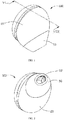
FIG. 1 is a schematic structural diagram of an earphone according to an implementation of the present disclosure. -
FIG. 2 is a schematic structural diagram of the earphone ofFIG. 1 viewed from another perspective. -
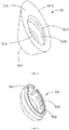
FIG. 3 is a perspective exploded view of the earphone ofFIG. 1 . -
FIG. 4 is a perspective exploded view of the earphone ofFIG. 2 . -
FIG. 5 is an enlarged view of a connecting member of the earphone ofFIG. 3 viewed from another perspective. -
FIG. 6 is an enlarged view of a cap body of the earphone ofFIG. 3 viewed from another perspective. -
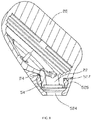
FIG. 7 is a cross-sectional view taken along a line VII-VII inFIG. 3 . -
FIG. 8 is a cross-sectional view taken along a line VIII-VIII inFig. 1 . - The technical solutions in the implementations of the present disclosure will be clearly and completely described below with reference to the accompanying drawings in the implementations of the present disclosure. Clearly, the described implementations are only a part of the implementations of the present disclosure, but not all the implementations. Based on the implementations in the present disclosure, all other implementations obtained by those skilled in the art without paying any creative labor are within the protection scope of the present disclosure.
- In addition, the descriptions of the following implementations are references to the accompanying drawings to illustrate specific implementations of the present disclosure that can be implemented. Directional terms mentioned in the present disclosure, such as "up", "down", "front", "rear", "left", "right", "inner", "outer", "side", etc., refer only to the directions of the accompanying drawings. Therefore, the direction words are used for better and clearer description and understanding of the present disclosure, rather than indicating or implying that the device or element referred to must have a specific orientation, be constructed and operated in a specific orientation, so it cannot be understood as a limitation of the present disclosure.
- In the description of the present disclosure, it should be noted that, unless otherwise clearly specified and defined, the terms "install", "couple", and "connect" should be understood in a broad sense. For example, it may be a fixed connection, a detachable connection, or an integrated connection; it may be a mechanical connection; it may be a direct connection, or an indirect connection through an intermediate medium, or it may be a connection between two components. For those of ordinary skill in the art, the specific meaning of the above terms in the present disclosure can be understood in specific situations.
- In addition, in the description of the present disclosure, unless otherwise stated, "plurality/multiple" means two or more. If a term "process" appears in the specification, it not only refers to an independent process, but also includes the expected effect of the process if it cannot be clearly distinguished from other processes. In addition, the range of values indicated by "∼" in this specification refers to the range of values described before and after "∼" as a minimum value and a maximum value, respectively. In the accompanying drawings, units with similar or identical structures are denoted by the same reference numerals.
- In an implementation, the present disclosure provides an ear cap capable of being detachably connected to a connecting rod of an earphone, where the connecting rod defines an earphone port. The ear cap includes a cap body and a connecting member arranged in the cap body. The cap body includes a first end surface, a second end surface, and an outer surface connected between the first end surface and the second end surface, where the first end surface and the second end surface are arranged opposite to each other. The first end surface includes a first outer edge arranged at a joint of the first end surface and the outer surface, and the second end surface includes a second outer edge arranged at a joint of the second end surface and the outer surface, where the distance between each point of a projection of the first outer edge on a reference plane and the second outer edge is different, where the reference plane includes a plane on which the second outer edge is located. The hardness of the connecting member is greater than the hardness of the cap body, where the connecting member is capable of being connected to the connecting rod.
- In an implementation, the present disclosure further provides an earphone including a housing and an ear cap. The housing includes a body and a connecting rod protruding from the body, where the connecting rod defines an earphone port. The ear cap is capable of being mounted on the connecting rod. The ear cap includes a cap body and a connecting member arranged in the cap body. The cap body includes a first end surface, a second end surface, and an outer surface connected between the first end surface and the second end surface, where the first end surface and the second end surface are arranged opposite to each other. The first end surface includes a first outer edge arranged at a joint of the first end surface and the outer surface, and the second end surface includes a second outer edge arranged at a joint of the second end surface and the outer surface, where the distance between each point of a projection of the first outer edge on a reference plane and the second outer edge is different, where the reference plane includes a plane on which the second outer edge is located. The hardness of the connecting member is greater than the hardness of the cap body, where the connecting member is capable of being connected to the connecting rod.
- Referring to
FIG. 1 to FIG. 4 , the present disclosure provides anearphone 100 which includes ahousing 20 and anear cap 50. Thehousing 20 includes abody 21 and a connectingrod 24 protruding from thebody 21. It can be understood that, theear cap 50 and at least part of thebody 21 are placed into an ear canal of a user when in use. Thebody 21 is hollow and defines a receiving cavity 203 (as illustrated inFIG. 6 ) therein. The connectingrod 24 defines an earphone port 22 (that is, a sound outlet) communicating with the receiving cavity 203 of thebody 21. Theear cap 50 is capable of being mounted on the connectingrod 24. Specifically, theear cap 50 is capable of being detachably connected to the connectingrod 24. Theear cap 50 includes ahollow cap body 52 and a connectingmember 54 arranged in thecap body 52. The connectingmember 54 is capable of being detachably connected to the connectingrod 24. Thecap body 52 includes afirst end surface 521, asecond end surface 522, and anouter surface 523 connected between thefirst end surface 521 and thesecond end surface 522, where thefirst end surface 521 and thesecond end surface 522 are arranged opposite to each other. Thecap body 52 defines asound output channel 524 penetrating thefirst end surface 521 and thesecond end surface 522. Thesound output channel 524 communicates with theearphone port 22 when theear cap 50 is mounted on the connectingrod 24. - The
first end surface 521 includes a firstouter edge 5201 arranged at a joint of thefirst end surface 521 and theouter surface 523, and thesecond end surface 522 includes a secondouter edge 5203 arranged at a joint of thesecond end surface 522 and theouter surface 523. The distance between each point of a projection of the firstouter edge 5201 on a reference plane and the secondouter edge 5203 is different, where the reference plane includes a plane on which the secondouter edge 5203 is located. - The projection of the first
outer edge 5201 on the reference plane partially overlaps or is misaligned with the secondouter edge 5203. Specifically, the secondouter edge 5203 may be located within an area surrounded by the projection of the firstouter edge 5201 on the reference plane, the secondouter edge 5203 may be located within the area surrounded by the projection of the firstouter edge 5201 on the reference plane and tangent to the projection of the firstouter edge 5201, or the secondouter edge 5203 intersects the projection of the firstouter edge 5201 on the reference plane. In the implementation, the shapes of the firstouter edge 5201 and the secondouter edge 5203 are both circular, the diameter of the firstouter edge 5201 is greater than the diameter of the secondouter edge 5203, the secondouter edge 5203 is located within the area surrounded by the projection of the firstouter edge 5201 on the reference plane, and a center of the secondouter edge 5203 is misaligned with a center of the projection of the firstouter edge 5201 on the reference plane. Thecap body 52 may be a symmetrical structure or an asymmetrical structure. - The distance between each point of the projection of the first
outer edge 5201 on the reference plane and the firstouter edge 5201 includes a maximum value and a minimum value. - The
earphone 100 provided by the present disclosure includes thehousing 20 provided with the connectingrod 24 and theear cap 50 provided with the connectingmember 54. Theear cap 50 is capable of being detachably connected to the connectingrod 24 through the connectingmember 54, so that theear cap 50 is firmly mounted on thehousing 20, and theear cap 50 has strong tensile strength to prevent theear cap 50 from detaching from thehousing 20. - The
housing 20 is provided with multiple components such as a multi-layer diaphragm, magnetic pole pieces, neodymium magnets, a thruster resistor for balancing the bass section to the middle section, and a rear resistor for balancing the bass section to the middle section, in the receiving cavity 203. The connectingrod 24 of thehousing 20 is made of hard materials, and an extension length of the connectingrod 24 is less than or equal to 2.5 mm. Thebody 21 is provided with afitting surface 25 from which the connectingrod 24 protrudes. In the implementation, thefitting surface 25 is an arc-shaped surface slightly convex outwards. Thebody 21 includes afront housing 211 and arear housing 212 connected to thefront housing 211. The connectingrod 24 and thefitting surface 25 are provided on thefront housing 211. - The hardness of the connecting
member 54 is greater than the hardness of thecap body 52. In an implementation, thecap body 52 and the connectingmember 54 may be formed into one body by double injection molding. Specifically, thecap body 52 and the connectingmember 54 may be formed by injection molding two different materials in the same set of molds, so that the moldedear cap 50 includes asoft cap body 52 and a hard connectingmember 54. In the implementation, thecap body 52 is made of soft plastic, and the connectingmember 54 is made of hard plastic. - In another implementation, the
cap body 52 and the connectingmember 54 may also be formed into one body by insert molding. Specifically, the connectingmember 54 is formed by hard material. The connectingmember 54 is first put into a mold, and then resin or molten material is injected into the mold to join and solidify the connectingmember 54 to form anintegrated cap body 52, so that thecap body 52 of theear cap 50 is made of soft material and the connectingmember 54 is made of a hard material. - In another implementation, the connecting
member 54 and thecap body 52 may also be connected together by engagement or gluing. In the implementation, the connectingmember 54 and thecap body 52 are connected together by engagement. - Referring to
FIG. 3 to FIG. 7 together, thecap body 52 has an asymmetric structure. Thefirst end surface 521 of thecap body 52 faces thehousing 20 and is configured fit thefitting surface 25. In the implementation, thefirst end surface 521 is an arc-shaped surface slightly concave inwards. The area of thefirst end surface 521 is greater than the area of thesecond end surface 522. In the implementation, a projection of thesecond end surface 522 on thefirst end surface 521 falls into thefirst end surface 521. The shape of thefirst end surface 521 and thesecond end surface 522 may be circular, oval, or waist-shaped, etc., and thecap body 52 is in the shape of a circular cone. In the implementation, the shapes of thefirst end surface 521 and thesecond end surface 522 are both waist-shaped. A cross section of thecap body 52 taken along a direction from thefirst end surface 521 to thesecond end surface 522 is a non-isosceles trapezoid, that is, one of the waist sides of the cross section is longer than the other. - The
cap body 52 defines thesound output channel 524 penetrating through two opposite end surfaces of thecap body 52, that is, thesound output channel 524 penetrates thefirst end surface 521 and thesecond end surface 522 of thecap body 52. Thecap body 52 defines anannular receiving groove 525 on an inner wall of thesound output channel 524, and the connectingmember 54 is positioned in the receivinggroove 525. Specifically, the receivinggroove 525 is adjacent to thefirst end surface 521, and the receivinggroove 525 is an annular groove continuously provided along a circumferential direction of thesound output channel 524. - The
cap body 52 is provided with a first connecting portion on an inner wall of the receivinggroove 525, the connectingmember 54 is provided with a second connecting portion on its outer wall, and thecap body 52 is detachably mounted on the connectingmember 54 through an engagement of the first connecting portion and the second connecting portion. In the implementation, one of an inner wall of the receivinggroove 525 of thecap body 52 and an outer wall of the connectingmember 54 is protruded with a positioning strip, and the other of the inner wall of the receivinggroove 525 and the outer wall of the connectingmember 54 is provided with a positioning slot, where the positioning strip is snapped into the positioning slot. That is, one of the first connecting portion and the second connecting portion is a positioning strip, and the other is a positioning slot matching the positioning strip. Specifically, in the implementation, the inner wall of the receivinggroove 525 is protruded with apositioning strip 527 for positioning the connectingmember 54. In the implementation, thepositioning strip 527 is arranged adjacent to thefirst end surface 521, and thepositioning strip 527 is an annular strip continuously protruded along the circumferential direction of thesound output channel 524. - As illustrated in
FIG. 6 , the connectingmember 54 has an annular structure. The outer wall of the connectingmember 54 is connected to the inner wall of the receivinggroove 525. Aninner cavity 541 of the connectingmember 54 communicates with thesound output channel 524. - Specifically, the connecting
member 54 is made of hard plastic or rubber, and the outer wall of the connectingmember 54 defines apositioning slot 540 corresponding to thepositioning strip 527 of thecap body 52. When the connectingmember 54 is received in the receivinggroove 525 of thecap body 52, thepositioning strip 527 is snapped into thepositioning slot 540, so that the connectingmember 54 and thecap body 52 are connected together. - The connecting
rod 24 is provided with a third connecting portion on its outer wall, the connectingmember 54 is further provided with a fourth connecting portion on its inner wall, and the connectingmember 54 is capable of being detachably connected to the connectingrod 24 through an engagement of the third connecting portion and the fourth connecting portion. In the implementation, the connectingrod 24 is provided with a connectingslot 242 on its outer wall along a circumferential direction, and the connectingmember 54 is provided with clampingstrips 542 on its inner wall, where the clamping strips 542 is snapped into the connectingslot 242 of the connectingrod 24. That is, the third connecting portion is the connectingslot 242, and the fourth connecting portion is the clamping strips 542. - Referring to
FIG. 7 andFIG. 8 together, when assembling theearphone 100, the connectingmember 54 is first received in the receivinggroove 525 of thecap body 52, and thepositioning strip 527 is engaged with thepositioning slot 540, so that the connectingmember 54 and thecap body 52 are connected together to form theear cap 50. Then theear cap 50 is mounted on the connectingrod 24. Specifically, the clamping strips 542 of theear cap 50 are engaged with the connectingslot 242 of the connectingrod 24, and thefirst end surface 521 is fitted to thefitting surface 25. Theouter surface 523 of theear cap 50 is smoothly butted with the outer surface of thehousing 20. Since thecap body 52 has an asymmetric structure, and thefirst end surface 521 is fit to thefitting surface 25, therefore, theear cap 50 can only be mounted on thehousing 20 according to a preset installation direction, which can prevent theear cap 50 from being mounted reversely or incorrectly on the connectingrod 24 of thehousing 20. That is, theear cap 50 cannot be mounted on the connectingrod 24 in the case of incorrect or reverse installation by consumers, so as to avoid bringing bad use experience for the consumers. In addition, theclamping strip 542 of theear cap 50 is engaged in the connectingslot 242 of the connectingrod 24, and both the connectingrod 24 and the connectingmember 54 are made of hard material, therefore, even if the extending length of the connectingrod 24 is short, the connection between theear cap 50 and the connectingrod 24 can also be firm and stable, so as to prevent theear cap 50 from detaching from the connectingrod 24. - In another implementation, the outer wall of the connecting
rod 24 is protruded with a clamping strip along the circumferential direction of the connectingrod 24, where the clamping strip continuously wraps the outer wall of the connectingrod 24 at least one round. The connectingmember 54 defines, on its inner wall, a connecting slot corresponding to the clamping strip, where the connection groove continuously wraps the inner wall of the connectingmember 54 at least one round. When the connectingmember 54 is mounted on the connectingrod 24, the clamping strip of the connectingrod 24 is snapped into the connecting slot of the connectingmember 54 to firmly connect theear cap 50 to the connectingrod 24. - In another implementation, the outer wall of the connecting
rod 24 is protruded with a plurality of clamping strips along the circumferential direction of the connectingrod 24, where the clamping strips circumferentially wraps the outer wall of the connectingrod 24 at least one round. The connectingmember 54 defines, on its inner wall, a plurality of connecting slots corresponding to the plurality of clamping strips. When the connectingmember 54 is mounted on the connectingrod 24, the clamping strips of the connectingrod 24 are snapped into the corresponding connecting slot of the connectingmember 54 to firmly connect theear cap 50 to the connectingrod 24. - In another implementation, the outer wall of the connecting
rod 24 is protruded with a plurality of bumps along the circumferential direction of the connectingrod 24, and the connectingmember 54 defines, on its inner wall, a plurality of connecting holes corresponding to the plurality of bumps. When the connectingmember 54 is mounted on the connectingrod 24, the plurality of bumps of the connectingrod 24 are respectively snapped into the corresponding connecting holes to firmly connect theear cap 50 to the connectingrod 24. - In another implementation, the connecting
rod 24 defines a plurality of connecting holes on its outer wall along its circumferential direction, and the inner wall of the connectingmember 54 is protruded with a plurality of bumps corresponding to the plurality of holes. When the connectingmember 54 is mounted on the connectingrod 24, the plurality of bumps of the connectingmember 54 are respectively snapped into the corresponding connecting holes to firmly connect theear cap 50 to the connectingrod 24. In another implementation, the connecting member and the connectingrod 24 can also be connected together by glue. - In another implementation, the outer wall of the connecting
member 54 is protruded with at least one positioning strip, where the at least one positioning strip wraps the outer wall of the connectingmember 54 at least one round in the circumferential direction of the connectingmember 54. The receivinggroove 525 of thecap body 52 defines, on its inner wall, at least one positioning slot corresponding to the positioning strip, where the at least one positioning slot wraps the inner wall of the receivinggroove 525 at least one round in the circumferential direction of the receivinggroove 525. When the connectingmember 54 is received in the receivinggroove 525, the positioning strip is snapped into the positioning slot to firmly connect the connectingmember 54 to thecap body 52. - In another implementation, the outer wall of the connecting
member 54 is protruded with a plurality of positioning strip, where the plurality of positioning strip wraps the outer wall of the connectingmember 54 at least one round in the circumferential direction of the connectingmember 54. The receivinggroove 525 of thecap body 52 defines, on its inner wall, a plurality of positioning slot corresponding to the positioning strip, where the plurality of positioning slot wraps the inner wall of the receivinggroove 525 at least one round in the circumferential direction of the receivinggroove 525. When the connectingmember 54 is received in the receivinggroove 525, the plurality of positioning strips are respectively snapped into the corresponding positioning slots to firmly connect the connectingmember 54 to thecap body 52. - The above is the implementations of the present disclosure. It should be noted that for those of ordinary skill in the art, several improvements and modifications can be made without departing from the principles of the implementations of the present disclosure. These improvements and modifications are also considered as the protection scope of the present disclosure.
Claims (15)
- An ear cap (50) capable of being detachably connected to a connecting rod (24) of an earphone (100), the connecting rod (24) defining an earphone port (22), and the ear cap (50) comprising:a cap body (52) comprising a first end surface (521), a second end surface (522), and an outer surface (523) connected between the first end surface (521) and the second end surface (522), wherein the first end surface (521) and the second end surface (522) are arranged opposite to each other, wherein the first end surface (521) comprises a first outer edge (5201) arranged at a joint of the first end surface (521) and the outer surface (523), and the second end surface (522) comprises a second outer edge (5203) arranged at a joint of the second end surface (522) and the outer surface (523), wherein the distance between each point of a projection of the first outer edge (5201) on a reference plane and the second outer edge (5203) is different, wherein the reference plane comprises a plane on which the second outer edge (5203) is located; anda connecting member (54) arranged in the cap body (52), wherein the hardness of the connecting member (54) is greater than the hardness of the cap body (52), wherein the connecting member (54) is capable of being detachably connected to the connecting rod (24).
- The ear cap (50) of claim 1, wherein the projection of the first outer edge (5201) on the reference plane partially overlaps or is misaligned with the second outer edge (5203).
- The ear cap (50) of claim 1, wherein the cap body (52) and the connecting member (54) are formed into one body by double injection molding or insert molding.
- The ear cap (50) of claim 1, wherein the connecting member (54) and the cap body (52) are connected together by engagement or gluing.
- The ear cap (50) of claim any one of claims 1 to 4, wherein the cap body (52) defines a sound output channel (524) penetrating the first end surface (521) and the second end surface (522) of the cap body (52), wherein the cap body (52) defines a receiving groove (525) on an inner wall of the sound output channel (524), and the connecting member (54) is positioned in the receiving groove (525).
- The ear cap (50) of claim 5, wherein the connecting member (54) has an annular structure, wherein an outer wall of the connecting member (54) is connected to an inner wall of the receiving groove (525), and an inner cavity (541) of the connecting member (54) communicates with the sound output channel (524).
- The ear cap (50) of claim 6, wherein the cap body (52) is provided with a first connecting portion on an inner wall of the receiving groove (525), the connecting member (54) is provided with a second connecting portion on its outer wall, and the cap body (52) is capable of being detachably mounted on the connecting member (54) through an engagement of the first connecting portion and the second connecting portion, wherein one of the first connecting portion and the second connecting portion is a positioning strip, and the other of the first connecting portion and the second connecting portion is a positioning slot matching the positioning strip, wherein the positioning strip is snapped into the positioning slot.
- The ear cap (50) of claim 6, wherein the connecting rod (24) is provided with a third connecting portion on its outer wall, the connecting member (54) is provided with a fourth connecting portion on its inner wall, and the connecting member (54) is capable of being detachably connected to the connecting rod (24) through an engagement of the third connecting portion and the fourth connecting portion, wherein one of the third connecting portion and the fourth connecting portion is a clamping strip or a plurality of bumps, and the other of the third connecting portion and the fourth connecting portion is a connecting slot corresponding to the clamping strip or a plurality of connecting holes corresponding to the plurality of bumps.
- The ear cap (50) of claim 5, wherein the area of the first end surface (521) is greater than the area of the second end surface (522), wherein a projection of the first end surface (521) on the second end surface covers the second end surface (522).
- The ear cap (50) of claim 9, wherein the first end surface (521) of the ear cap (50) is attached to a fitting surface (25) of the earphone (100) from which the connecting rod (24) protrudes.
- The ear cap (50) of claim 9, wherein the cap body (52) is in the shape of a circular cone, a cross section of the cap body (52) taken along a direction from the first end surface (521) to the second end surface (522) is a non-isosceles trapezoid, and one of the waist sides of the cross section is longer than the other.
- An earphone (100) comprising:a housing (20) comprising a body (21) and a connecting rod (24) protruding from the body (21); andthe ear cap (50) of any one of claims 1 to 11, wherein the ear cap (50) is capable of being mounted on the connecting rod (24).
- The earphone (100) of claim 12, wherein an extension length of the connecting rod (24) is less than or equal to 2.5 mm;
wherein the connecting rod (24) is made of hard materials, and the connecting member (54) of the ear cap (50) is made of hard materials. - The earphone (100) of claim 12, wherein the housing (20) is provided with a fitting surface (25) from which the connecting rod (24) protrudes, and the first end surface (521) of the ear cap (50) is attached to the fitting surface (25), wherein the outer surface (523) of the ear cap (50) is smoothly butted with the outer surface of the housing (20), wherein the fitting surface (25) is an arc-shaped surface slightly convex outwards, and the first end surface (521) is an arc-shaped surface slightly concave inwards.
- The earphone (100) of claim 12, wherein the connecting rod (24) defines an earphone port (22), and the cap body (52) defines a sound output channel (524) penetrating the first end surface (521) and the second end surface (522) of the cap body (52), wherein the sound output channel (524) communicates with the earphone port (22) when the ear cap (50) is mounted on the connecting rod (24).
Applications Claiming Priority (1)
| Application Number | Priority Date | Filing Date | Title |
|---|---|---|---|
| CN201921578581.1U CN211152159U (en) | 2019-09-20 | 2019-09-20 | Earcap and earphone |
Publications (2)
| Publication Number | Publication Date |
|---|---|
| EP3796674A1 true EP3796674A1 (en) | 2021-03-24 |
| EP3796674B1 EP3796674B1 (en) | 2023-05-31 |
Family
ID=71738051
Family Applications (1)
| Application Number | Title | Priority Date | Filing Date |
|---|---|---|---|
| EP20186904.7A Active EP3796674B1 (en) | 2019-09-20 | 2020-07-21 | Ear cap and earphone |
Country Status (4)
| Country | Link |
|---|---|
| US (1) | US11146879B2 (en) |
| EP (1) | EP3796674B1 (en) |
| CN (1) | CN211152159U (en) |
| WO (1) | WO2021051994A1 (en) |
Families Citing this family (1)
| Publication number | Priority date | Publication date | Assignee | Title |
|---|---|---|---|---|
| CN120343448B (en) * | 2021-10-29 | 2026-04-28 | 荣耀终端股份有限公司 | Speaker module and earphone |
Citations (4)
| Publication number | Priority date | Publication date | Assignee | Title |
|---|---|---|---|---|
| WO2009086555A1 (en) * | 2007-12-31 | 2009-07-09 | Koss Corporation | Adjustable shape earphone |
| KR101363989B1 (en) * | 2013-06-04 | 2014-02-18 | 윤영은 | Eartip capable of allowing inflow of sound from outside |
| KR101503327B1 (en) * | 2014-09-18 | 2015-03-18 | 주식회사 애니모드 | Variable earphones for ear canal adaptation |
| KR101562129B1 (en) * | 2014-05-23 | 2015-10-21 | 이준민 | hearing protection apparatus of earphone |
Family Cites Families (24)
| Publication number | Priority date | Publication date | Assignee | Title |
|---|---|---|---|---|
| US7580537B2 (en) * | 1998-11-25 | 2009-08-25 | Insound Medical, Inc. | Sealing retainer for extended wear hearing devices |
| WO2006104981A2 (en) * | 2005-03-28 | 2006-10-05 | Sound Id | Non-occluding ear module for a personal sound system |
| US8873790B2 (en) * | 2011-07-01 | 2014-10-28 | Apple Inc. | Non-occluding earbuds and methods for making the same |
| US8737669B2 (en) * | 2011-07-28 | 2014-05-27 | Bose Corporation | Earpiece passive noise attenuating |
| US8800712B2 (en) * | 2011-08-25 | 2014-08-12 | Magnatone Hearing Aid Corporation | Ear tip piece for attenuating sound |
| CN103384356A (en) * | 2012-05-03 | 2013-11-06 | 鸿富锦精密工业(深圳)有限公司 | Earphone |
| KR102073793B1 (en) * | 2013-08-29 | 2020-02-05 | 삼성전자 주식회사 | Audio Accessory`s cover and Audio Accessory thereof, and Electronic Device supporting the same |
| US9197956B2 (en) * | 2013-09-04 | 2015-11-24 | Etymotic Research, Inc. | Comformable eartip |
| US9462366B2 (en) * | 2014-03-27 | 2016-10-04 | Bose Corporation | Earpieces having flexible flaps |
| US9900681B2 (en) * | 2015-03-05 | 2018-02-20 | Inca Street Sound, LLC | Earbud headphone adapter |
| CN204616041U (en) * | 2015-05-05 | 2015-09-02 | 庄植财 | A kind of In-Ear Headphones |
| CN115334401B (en) * | 2015-09-30 | 2024-10-29 | 苹果公司 | Headset earplug with internal support member for the earplug body |
| CN206260066U (en) * | 2016-10-19 | 2017-06-16 | 深圳市冠旭电子股份有限公司 | A kind of In-Ear Headphones structure |
| DE102017105767A1 (en) | 2017-03-17 | 2018-09-20 | Sennheiser Electronic Gmbh & Co. Kg | Earphones with separate microphones for binaural recordings and to telephone |
| CN207184751U (en) * | 2017-05-08 | 2018-04-03 | 珠海市天韵电子科技有限公司 | In-Ear Headphones |
| US10542341B2 (en) * | 2017-06-29 | 2020-01-21 | Starkey Laboratories, Inc. | Flanged earbud and hearing device including same |
| US10986432B2 (en) * | 2017-06-30 | 2021-04-20 | Bose Corporation | Customized ear tips |
| US20190166438A1 (en) * | 2017-11-30 | 2019-05-30 | Earlens Corporation | Ear tip designs |
| CN109104661A (en) * | 2018-08-17 | 2018-12-28 | 深圳市睿良实业发展有限公司 | The production method of duct-type bluetooth headset and duct-type bluetooth headset |
| US10667030B2 (en) * | 2018-08-31 | 2020-05-26 | Bose Corporation | Earpiece tip and related earpiece |
| US10652644B2 (en) * | 2018-09-20 | 2020-05-12 | Apple Inc. | Ear tip designed to enable in-ear detect with pressure change in acoustic volume |
| CN208863041U (en) * | 2018-09-27 | 2019-05-14 | 安克创新科技股份有限公司 | A kind of earcap |
| US10820084B2 (en) * | 2019-01-07 | 2020-10-27 | Bose Corporation | Ear tip sealing structure |
| US10999670B2 (en) * | 2019-01-07 | 2021-05-04 | Bose Corporation | Ear tip sealing structure |
-
2019
- 2019-09-20 CN CN201921578581.1U patent/CN211152159U/en active Active
-
2020
- 2020-07-21 EP EP20186904.7A patent/EP3796674B1/en active Active
- 2020-07-21 WO PCT/CN2020/103248 patent/WO2021051994A1/en not_active Ceased
- 2020-08-24 US US17/000,682 patent/US11146879B2/en active Active
Patent Citations (4)
| Publication number | Priority date | Publication date | Assignee | Title |
|---|---|---|---|---|
| WO2009086555A1 (en) * | 2007-12-31 | 2009-07-09 | Koss Corporation | Adjustable shape earphone |
| KR101363989B1 (en) * | 2013-06-04 | 2014-02-18 | 윤영은 | Eartip capable of allowing inflow of sound from outside |
| KR101562129B1 (en) * | 2014-05-23 | 2015-10-21 | 이준민 | hearing protection apparatus of earphone |
| KR101503327B1 (en) * | 2014-09-18 | 2015-03-18 | 주식회사 애니모드 | Variable earphones for ear canal adaptation |
Also Published As
| Publication number | Publication date |
|---|---|
| WO2021051994A1 (en) | 2021-03-25 |
| US11146879B2 (en) | 2021-10-12 |
| EP3796674B1 (en) | 2023-05-31 |
| US20210092503A1 (en) | 2021-03-25 |
| CN211152159U (en) | 2020-07-31 |
Similar Documents
| Publication | Publication Date | Title |
|---|---|---|
| US20130294634A1 (en) | Earphone set with interchangeable in-ear and in-concha caps | |
| US9838770B2 (en) | Seamless earbud structures and methods for making the same | |
| US9025807B2 (en) | Couplable hearing apparatus for a hearing device, coupling element and hearing device | |
| US20030081794A1 (en) | Insert earphone | |
| US11991495B2 (en) | Modular earpiece adaptor | |
| US11146879B2 (en) | Ear cap and earphone | |
| CN106256134A (en) | There is the receiver of flexible flap | |
| EP3264791A1 (en) | Earphone | |
| WO2023051008A1 (en) | Earphone cap and earphone | |
| US20110249855A1 (en) | Earphone | |
| CN213990984U (en) | Earcap and earphone | |
| US10291974B2 (en) | Ambidextrous earpiece mold | |
| CN210469684U (en) | Fixed structure and in-ear headphones | |
| US20230040338A1 (en) | Bluetooth glasses | |
| EP3550852B1 (en) | A joiner for a receiver assembly | |
| CN104972808A (en) | Core of pencil sharpener | |
| CN211320420U (en) | Plug connecting device of clamping type coupler | |
| US10820074B2 (en) | Gradient micro-electro-mechanical (MEMS) microphone assembly | |
| CN209882021U (en) | Earphone head outer cover of headphone | |
| CN221227708U (en) | Headset earphone | |
| WO2017152388A1 (en) | Bluetooth earphone | |
| CN223219189U (en) | Laminating formula clamp ear bluetooth headset | |
| WO2016116732A1 (en) | In-ear monitor | |
| CN217591058U (en) | Loudspeaker and earphone | |
| CN218473336U (en) | Earphone sleeve and earphone |
Legal Events
| Date | Code | Title | Description |
|---|---|---|---|
| PUAI | Public reference made under article 153(3) epc to a published international application that has entered the european phase |
Free format text: ORIGINAL CODE: 0009012 |
|
| STAA | Information on the status of an ep patent application or granted ep patent |
Free format text: STATUS: THE APPLICATION HAS BEEN PUBLISHED |
|
| AK | Designated contracting states |
Kind code of ref document: A1 Designated state(s): AL AT BE BG CH CY CZ DE DK EE ES FI FR GB GR HR HU IE IS IT LI LT LU LV MC MK MT NL NO PL PT RO RS SE SI SK SM TR |
|
| AX | Request for extension of the european patent |
Extension state: BA ME |
|
| STAA | Information on the status of an ep patent application or granted ep patent |
Free format text: STATUS: REQUEST FOR EXAMINATION WAS MADE |
|
| 17P | Request for examination filed |
Effective date: 20210714 |
|
| RBV | Designated contracting states (corrected) |
Designated state(s): AL AT BE BG CH CY CZ DE DK EE ES FI FR GB GR HR HU IE IS IT LI LT LU LV MC MK MT NL NO PL PT RO RS SE SI SK SM TR |
|
| GRAP | Despatch of communication of intention to grant a patent |
Free format text: ORIGINAL CODE: EPIDOSNIGR1 |
|
| STAA | Information on the status of an ep patent application or granted ep patent |
Free format text: STATUS: GRANT OF PATENT IS INTENDED |
|
| INTG | Intention to grant announced |
Effective date: 20230214 |
|
| GRAS | Grant fee paid |
Free format text: ORIGINAL CODE: EPIDOSNIGR3 |
|
| GRAA | (expected) grant |
Free format text: ORIGINAL CODE: 0009210 |
|
| STAA | Information on the status of an ep patent application or granted ep patent |
Free format text: STATUS: THE PATENT HAS BEEN GRANTED |
|
| AK | Designated contracting states |
Kind code of ref document: B1 Designated state(s): AL AT BE BG CH CY CZ DE DK EE ES FI FR GB GR HR HU IE IS IT LI LT LU LV MC MK MT NL NO PL PT RO RS SE SI SK SM TR |
|
| REG | Reference to a national code |
Ref country code: GB Ref legal event code: FG4D Ref country code: CH Ref legal event code: EP |
|
| REG | Reference to a national code |
Ref country code: AT Ref legal event code: REF Ref document number: 1571727 Country of ref document: AT Kind code of ref document: T Effective date: 20230615 Ref country code: DE Ref legal event code: R096 Ref document number: 602020011268 Country of ref document: DE |
|
| REG | Reference to a national code |
Ref country code: IE Ref legal event code: FG4D |
|
| P01 | Opt-out of the competence of the unified patent court (upc) registered |
Effective date: 20230525 |
|
| REG | Reference to a national code |
Ref country code: LT Ref legal event code: MG9D |
|
| REG | Reference to a national code |
Ref country code: NL Ref legal event code: MP Effective date: 20230531 |
|
| REG | Reference to a national code |
Ref country code: AT Ref legal event code: MK05 Ref document number: 1571727 Country of ref document: AT Kind code of ref document: T Effective date: 20230531 |
|
| PG25 | Lapsed in a contracting state [announced via postgrant information from national office to epo] |
Ref country code: SE Free format text: LAPSE BECAUSE OF FAILURE TO SUBMIT A TRANSLATION OF THE DESCRIPTION OR TO PAY THE FEE WITHIN THE PRESCRIBED TIME-LIMIT Effective date: 20230531 Ref country code: NO Free format text: LAPSE BECAUSE OF FAILURE TO SUBMIT A TRANSLATION OF THE DESCRIPTION OR TO PAY THE FEE WITHIN THE PRESCRIBED TIME-LIMIT Effective date: 20230831 Ref country code: ES Free format text: LAPSE BECAUSE OF FAILURE TO SUBMIT A TRANSLATION OF THE DESCRIPTION OR TO PAY THE FEE WITHIN THE PRESCRIBED TIME-LIMIT Effective date: 20230531 Ref country code: AT Free format text: LAPSE BECAUSE OF FAILURE TO SUBMIT A TRANSLATION OF THE DESCRIPTION OR TO PAY THE FEE WITHIN THE PRESCRIBED TIME-LIMIT Effective date: 20230531 |
|
| PG25 | Lapsed in a contracting state [announced via postgrant information from national office to epo] |
Ref country code: RS Free format text: LAPSE BECAUSE OF FAILURE TO SUBMIT A TRANSLATION OF THE DESCRIPTION OR TO PAY THE FEE WITHIN THE PRESCRIBED TIME-LIMIT Effective date: 20230531 Ref country code: PL Free format text: LAPSE BECAUSE OF FAILURE TO SUBMIT A TRANSLATION OF THE DESCRIPTION OR TO PAY THE FEE WITHIN THE PRESCRIBED TIME-LIMIT Effective date: 20230531 Ref country code: NL Free format text: LAPSE BECAUSE OF FAILURE TO SUBMIT A TRANSLATION OF THE DESCRIPTION OR TO PAY THE FEE WITHIN THE PRESCRIBED TIME-LIMIT Effective date: 20230531 Ref country code: LV Free format text: LAPSE BECAUSE OF FAILURE TO SUBMIT A TRANSLATION OF THE DESCRIPTION OR TO PAY THE FEE WITHIN THE PRESCRIBED TIME-LIMIT Effective date: 20230531 Ref country code: LT Free format text: LAPSE BECAUSE OF FAILURE TO SUBMIT A TRANSLATION OF THE DESCRIPTION OR TO PAY THE FEE WITHIN THE PRESCRIBED TIME-LIMIT Effective date: 20230531 Ref country code: IS Free format text: LAPSE BECAUSE OF FAILURE TO SUBMIT A TRANSLATION OF THE DESCRIPTION OR TO PAY THE FEE WITHIN THE PRESCRIBED TIME-LIMIT Effective date: 20230930 Ref country code: HR Free format text: LAPSE BECAUSE OF FAILURE TO SUBMIT A TRANSLATION OF THE DESCRIPTION OR TO PAY THE FEE WITHIN THE PRESCRIBED TIME-LIMIT Effective date: 20230531 Ref country code: GR Free format text: LAPSE BECAUSE OF FAILURE TO SUBMIT A TRANSLATION OF THE DESCRIPTION OR TO PAY THE FEE WITHIN THE PRESCRIBED TIME-LIMIT Effective date: 20230901 |
|
| PG25 | Lapsed in a contracting state [announced via postgrant information from national office to epo] |
Ref country code: FI Free format text: LAPSE BECAUSE OF FAILURE TO SUBMIT A TRANSLATION OF THE DESCRIPTION OR TO PAY THE FEE WITHIN THE PRESCRIBED TIME-LIMIT Effective date: 20230531 |
|
| PG25 | Lapsed in a contracting state [announced via postgrant information from national office to epo] |
Ref country code: SK Free format text: LAPSE BECAUSE OF FAILURE TO SUBMIT A TRANSLATION OF THE DESCRIPTION OR TO PAY THE FEE WITHIN THE PRESCRIBED TIME-LIMIT Effective date: 20230531 |
|
| PG25 | Lapsed in a contracting state [announced via postgrant information from national office to epo] |
Ref country code: SM Free format text: LAPSE BECAUSE OF FAILURE TO SUBMIT A TRANSLATION OF THE DESCRIPTION OR TO PAY THE FEE WITHIN THE PRESCRIBED TIME-LIMIT Effective date: 20230531 Ref country code: SK Free format text: LAPSE BECAUSE OF FAILURE TO SUBMIT A TRANSLATION OF THE DESCRIPTION OR TO PAY THE FEE WITHIN THE PRESCRIBED TIME-LIMIT Effective date: 20230531 Ref country code: RO Free format text: LAPSE BECAUSE OF FAILURE TO SUBMIT A TRANSLATION OF THE DESCRIPTION OR TO PAY THE FEE WITHIN THE PRESCRIBED TIME-LIMIT Effective date: 20230531 Ref country code: PT Free format text: LAPSE BECAUSE OF FAILURE TO SUBMIT A TRANSLATION OF THE DESCRIPTION OR TO PAY THE FEE WITHIN THE PRESCRIBED TIME-LIMIT Effective date: 20231002 Ref country code: EE Free format text: LAPSE BECAUSE OF FAILURE TO SUBMIT A TRANSLATION OF THE DESCRIPTION OR TO PAY THE FEE WITHIN THE PRESCRIBED TIME-LIMIT Effective date: 20230531 Ref country code: DK Free format text: LAPSE BECAUSE OF FAILURE TO SUBMIT A TRANSLATION OF THE DESCRIPTION OR TO PAY THE FEE WITHIN THE PRESCRIBED TIME-LIMIT Effective date: 20230531 Ref country code: CZ Free format text: LAPSE BECAUSE OF FAILURE TO SUBMIT A TRANSLATION OF THE DESCRIPTION OR TO PAY THE FEE WITHIN THE PRESCRIBED TIME-LIMIT Effective date: 20230531 |
|
| PG25 | Lapsed in a contracting state [announced via postgrant information from national office to epo] |
Ref country code: MC Free format text: LAPSE BECAUSE OF FAILURE TO SUBMIT A TRANSLATION OF THE DESCRIPTION OR TO PAY THE FEE WITHIN THE PRESCRIBED TIME-LIMIT Effective date: 20230531 |
|
| PG25 | Lapsed in a contracting state [announced via postgrant information from national office to epo] |
Ref country code: MC Free format text: LAPSE BECAUSE OF FAILURE TO SUBMIT A TRANSLATION OF THE DESCRIPTION OR TO PAY THE FEE WITHIN THE PRESCRIBED TIME-LIMIT Effective date: 20230531 |
|
| REG | Reference to a national code |
Ref country code: CH Ref legal event code: PL |
|
| REG | Reference to a national code |
Ref country code: DE Ref legal event code: R097 Ref document number: 602020011268 Country of ref document: DE |
|
| REG | Reference to a national code |
Ref country code: BE Ref legal event code: MM Effective date: 20230731 |
|
| PG25 | Lapsed in a contracting state [announced via postgrant information from national office to epo] |
Ref country code: LU Free format text: LAPSE BECAUSE OF NON-PAYMENT OF DUE FEES Effective date: 20230721 |
|
| PG25 | Lapsed in a contracting state [announced via postgrant information from national office to epo] |
Ref country code: LU Free format text: LAPSE BECAUSE OF NON-PAYMENT OF DUE FEES Effective date: 20230721 |
|
| PLBE | No opposition filed within time limit |
Free format text: ORIGINAL CODE: 0009261 |
|
| STAA | Information on the status of an ep patent application or granted ep patent |
Free format text: STATUS: NO OPPOSITION FILED WITHIN TIME LIMIT |
|
| REG | Reference to a national code |
Ref country code: IE Ref legal event code: MM4A |
|
| PG25 | Lapsed in a contracting state [announced via postgrant information from national office to epo] |
Ref country code: CH Free format text: LAPSE BECAUSE OF NON-PAYMENT OF DUE FEES Effective date: 20230731 |
|
| PG25 | Lapsed in a contracting state [announced via postgrant information from national office to epo] |
Ref country code: SI Free format text: LAPSE BECAUSE OF FAILURE TO SUBMIT A TRANSLATION OF THE DESCRIPTION OR TO PAY THE FEE WITHIN THE PRESCRIBED TIME-LIMIT Effective date: 20230531 |
|
| 26N | No opposition filed |
Effective date: 20240301 |
|
| PG25 | Lapsed in a contracting state [announced via postgrant information from national office to epo] |
Ref country code: SI Free format text: LAPSE BECAUSE OF FAILURE TO SUBMIT A TRANSLATION OF THE DESCRIPTION OR TO PAY THE FEE WITHIN THE PRESCRIBED TIME-LIMIT Effective date: 20230531 Ref country code: IT Free format text: LAPSE BECAUSE OF FAILURE TO SUBMIT A TRANSLATION OF THE DESCRIPTION OR TO PAY THE FEE WITHIN THE PRESCRIBED TIME-LIMIT Effective date: 20230531 Ref country code: BE Free format text: LAPSE BECAUSE OF NON-PAYMENT OF DUE FEES Effective date: 20230731 |
|
| PG25 | Lapsed in a contracting state [announced via postgrant information from national office to epo] |
Ref country code: IE Free format text: LAPSE BECAUSE OF NON-PAYMENT OF DUE FEES Effective date: 20230721 |
|
| PG25 | Lapsed in a contracting state [announced via postgrant information from national office to epo] |
Ref country code: IE Free format text: LAPSE BECAUSE OF NON-PAYMENT OF DUE FEES Effective date: 20230721 |
|
| PG25 | Lapsed in a contracting state [announced via postgrant information from national office to epo] |
Ref country code: BG Free format text: LAPSE BECAUSE OF FAILURE TO SUBMIT A TRANSLATION OF THE DESCRIPTION OR TO PAY THE FEE WITHIN THE PRESCRIBED TIME-LIMIT Effective date: 20230531 |
|
| PG25 | Lapsed in a contracting state [announced via postgrant information from national office to epo] |
Ref country code: BG Free format text: LAPSE BECAUSE OF FAILURE TO SUBMIT A TRANSLATION OF THE DESCRIPTION OR TO PAY THE FEE WITHIN THE PRESCRIBED TIME-LIMIT Effective date: 20230531 |
|
| GBPC | Gb: european patent ceased through non-payment of renewal fee |
Effective date: 20240721 |
|
| PG25 | Lapsed in a contracting state [announced via postgrant information from national office to epo] |
Ref country code: GB Free format text: LAPSE BECAUSE OF NON-PAYMENT OF DUE FEES Effective date: 20240721 |
|
| PG25 | Lapsed in a contracting state [announced via postgrant information from national office to epo] |
Ref country code: CY Free format text: LAPSE BECAUSE OF FAILURE TO SUBMIT A TRANSLATION OF THE DESCRIPTION OR TO PAY THE FEE WITHIN THE PRESCRIBED TIME-LIMIT; INVALID AB INITIO Effective date: 20200721 |
|
| PG25 | Lapsed in a contracting state [announced via postgrant information from national office to epo] |
Ref country code: HU Free format text: LAPSE BECAUSE OF FAILURE TO SUBMIT A TRANSLATION OF THE DESCRIPTION OR TO PAY THE FEE WITHIN THE PRESCRIBED TIME-LIMIT; INVALID AB INITIO Effective date: 20200721 |
|
| PGFP | Annual fee paid to national office [announced via postgrant information from national office to epo] |
Ref country code: DE Payment date: 20250724 Year of fee payment: 6 |
|
| PGFP | Annual fee paid to national office [announced via postgrant information from national office to epo] |
Ref country code: FR Payment date: 20250722 Year of fee payment: 6 |
|
| PG25 | Lapsed in a contracting state [announced via postgrant information from national office to epo] |
Ref country code: TR Free format text: LAPSE BECAUSE OF FAILURE TO SUBMIT A TRANSLATION OF THE DESCRIPTION OR TO PAY THE FEE WITHIN THE PRESCRIBED TIME-LIMIT Effective date: 20230531 |