EP3796659A1 - Image encoding device, encoded stream extraction device, and image decoding device - Google Patents
Image encoding device, encoded stream extraction device, and image decoding device Download PDFInfo
- Publication number
- EP3796659A1 EP3796659A1 EP19802509.0A EP19802509A EP3796659A1 EP 3796659 A1 EP3796659 A1 EP 3796659A1 EP 19802509 A EP19802509 A EP 19802509A EP 3796659 A1 EP3796659 A1 EP 3796659A1
- Authority
- EP
- European Patent Office
- Prior art keywords
- subpicture
- coding
- image
- unit
- coded data
- Prior art date
- Legal status (The legal status is an assumption and is not a legal conclusion. Google has not performed a legal analysis and makes no representation as to the accuracy of the status listed.)
- Pending
Links
Images








Classifications
-
- H—ELECTRICITY
- H04—ELECTRIC COMMUNICATION TECHNIQUE
- H04N—PICTORIAL COMMUNICATION, e.g. TELEVISION
- H04N19/00—Methods or arrangements for coding, decoding, compressing or decompressing digital video signals
- H04N19/10—Methods or arrangements for coding, decoding, compressing or decompressing digital video signals using adaptive coding
- H04N19/102—Methods or arrangements for coding, decoding, compressing or decompressing digital video signals using adaptive coding characterised by the element, parameter or selection affected or controlled by the adaptive coding
- H04N19/119—Adaptive subdivision aspects, e.g. subdivision of a picture into rectangular or non-rectangular coding blocks
-
- H—ELECTRICITY
- H04—ELECTRIC COMMUNICATION TECHNIQUE
- H04N—PICTORIAL COMMUNICATION, e.g. TELEVISION
- H04N19/00—Methods or arrangements for coding, decoding, compressing or decompressing digital video signals
- H04N19/70—Methods or arrangements for coding, decoding, compressing or decompressing digital video signals characterised by syntax aspects related to video coding, e.g. related to compression standards
-
- H—ELECTRICITY
- H04—ELECTRIC COMMUNICATION TECHNIQUE
- H04N—PICTORIAL COMMUNICATION, e.g. TELEVISION
- H04N19/00—Methods or arrangements for coding, decoding, compressing or decompressing digital video signals
- H04N19/10—Methods or arrangements for coding, decoding, compressing or decompressing digital video signals using adaptive coding
- H04N19/134—Methods or arrangements for coding, decoding, compressing or decompressing digital video signals using adaptive coding characterised by the element, parameter or criterion affecting or controlling the adaptive coding
- H04N19/167—Position within a video image, e.g. region of interest [ROI]
-
- H—ELECTRICITY
- H04—ELECTRIC COMMUNICATION TECHNIQUE
- H04N—PICTORIAL COMMUNICATION, e.g. TELEVISION
- H04N19/00—Methods or arrangements for coding, decoding, compressing or decompressing digital video signals
- H04N19/10—Methods or arrangements for coding, decoding, compressing or decompressing digital video signals using adaptive coding
- H04N19/169—Methods or arrangements for coding, decoding, compressing or decompressing digital video signals using adaptive coding characterised by the coding unit, i.e. the structural portion or semantic portion of the video signal being the object or the subject of the adaptive coding
- H04N19/17—Methods or arrangements for coding, decoding, compressing or decompressing digital video signals using adaptive coding characterised by the coding unit, i.e. the structural portion or semantic portion of the video signal being the object or the subject of the adaptive coding the unit being an image region, e.g. an object
- H04N19/172—Methods or arrangements for coding, decoding, compressing or decompressing digital video signals using adaptive coding characterised by the coding unit, i.e. the structural portion or semantic portion of the video signal being the object or the subject of the adaptive coding the unit being an image region, e.g. an object the region being a picture, frame or field
-
- H—ELECTRICITY
- H04—ELECTRIC COMMUNICATION TECHNIQUE
- H04N—PICTORIAL COMMUNICATION, e.g. TELEVISION
- H04N19/00—Methods or arrangements for coding, decoding, compressing or decompressing digital video signals
- H04N19/10—Methods or arrangements for coding, decoding, compressing or decompressing digital video signals using adaptive coding
- H04N19/169—Methods or arrangements for coding, decoding, compressing or decompressing digital video signals using adaptive coding characterised by the coding unit, i.e. the structural portion or semantic portion of the video signal being the object or the subject of the adaptive coding
- H04N19/17—Methods or arrangements for coding, decoding, compressing or decompressing digital video signals using adaptive coding characterised by the coding unit, i.e. the structural portion or semantic portion of the video signal being the object or the subject of the adaptive coding the unit being an image region, e.g. an object
- H04N19/174—Methods or arrangements for coding, decoding, compressing or decompressing digital video signals using adaptive coding characterised by the coding unit, i.e. the structural portion or semantic portion of the video signal being the object or the subject of the adaptive coding the unit being an image region, e.g. an object the region being a slice, e.g. a line of blocks or a group of blocks
-
- H—ELECTRICITY
- H04—ELECTRIC COMMUNICATION TECHNIQUE
- H04N—PICTORIAL COMMUNICATION, e.g. TELEVISION
- H04N19/00—Methods or arrangements for coding, decoding, compressing or decompressing digital video signals
- H04N19/40—Methods or arrangements for coding, decoding, compressing or decompressing digital video signals using video transcoding, i.e. partial or full decoding of a coded input stream followed by re-encoding of the decoded output stream
-
- H—ELECTRICITY
- H04—ELECTRIC COMMUNICATION TECHNIQUE
- H04N—PICTORIAL COMMUNICATION, e.g. TELEVISION
- H04N19/00—Methods or arrangements for coding, decoding, compressing or decompressing digital video signals
- H04N19/90—Methods or arrangements for coding, decoding, compressing or decompressing digital video signals using coding techniques not provided for in groups H04N19/10-H04N19/85, e.g. fractals
- H04N19/96—Tree coding, e.g. quad-tree coding
Definitions
- Embodiments of the present invention are related to an image coding apparatus, a coding stream extraction apparatus, and an image decoding apparatus.
- a video coding apparatus that generates coded data by encoding the video and a video decoding apparatus that generates a decoded image by decoding the coded data are used.
- an image (picture) configuring video is managed using a hierarchical structure formed from slices acquired by dividing the image, coding tree units (CTUs) acquired by dividing a slice, coding units (CUs) acquired by dividing a coding tree unit, prediction units (PUs) that are blocks acquired by dividing a coding unit, and transform units (TUs), and the image is encoded/decoded for each CU.
- CTUs coding tree units
- CUs coding units
- PUs prediction units
- TUs transform units
- a prediction image is generated based on a locally decoded image acquired by encoding/decoding an input image, and a prediction residue (also referred to as a "differential image” or a "residual image”) acquired by subtracting the prediction image from the input image (original image) is encoded.
- a prediction residue also referred to as a "differential image” or a "residual image”
- methods for generating a prediction image there are an inter-screen prediction (inter prediction) method and an intra-screen prediction (intra prediction) method.
- Patent Literature 1 a technology of independently encoding each tile in a time direction is disclosed.
- Non-Patent Literature 1 a technology relating to tiles of H.265/HEVC and the like is disclosed.
- Patent Literature 1 JP 6241504 B (issued on December 6, 2016 )
- Non-Patent Literature 1 ITU-T H. 265, "High efficiency video coding," SERIES H: AUDIOVISUAL and MULTIMEDIA SYSTEMS Infrastructure of audiovisual services - Coding of moving video, ISO/IEC 23008-2, December 2016
- Patent Literature 1 and Non-Patent Literature 1 in a case that coded data of only a specific area is to be generated by extracting a part from coded data of an entire image for displaying only the specific area of a picture, there may be a need to extensively rewrite coded data of slice data and the like.
- only one picture (view) can be associated with coded data, and a specific picture (only a view) cannot be extracted and decoded from a coded picture.
- the present invention is related to a device that decodes a picture using coded data corresponding to a partial area that can be easily extracted from coded data of an entire picture.
- the present invention is related to a device that encodes coded data of an entire picture from which coded data corresponding to a partial area can be extracted.
- the present invention is related to a stream extraction device that extracts coded data corresponding to a specific area from coded data that can be easily extracted.
- an image coding apparatus that generates coded data by encoding image data
- the image coding apparatus including: a coded data generating unit configured to generate the coded data including image data for a subpicture acquired by dividing a picture, in which the coded data generating unit generates, on a per subpicture basis, a subpicture header including subpicture identification information used for identifying the subpicture, and includes the generated subpicture header in the coded data.
- a coding stream extraction apparatus that generates output coded data from input coded data
- the coding stream extraction apparatus including: an encoding unit configured to generate the output coded data, in which the input coded data includes image data for a subpicture acquired by dividing a picture and a subpicture header that includes subpicture identification information used for identifying the subpicture, the subpicture header being generated on a per subpicture basis, and the encoding unit generates coded data including a subpicture parameter set including one or a plurality of pieces of subpicture identification information, and image data for the subpicture.
- an image decoding apparatus that decodes coded data
- the image decoding apparatus including: a decoding unit configured to generate a decoded image by decoding the coded data, in which the coded data includes image data for a subpicture acquired by dividing a picture, a subpicture header that includes subpicture identification information used for identifying the subpicture, subpicture header being generated on a per subpicture basis, and a subpicture parameter set including one or more pieces of subpicture identification information, and the decoding unit generates a decoded image by referring to the subpicture parameter set and the subpicture header included in the coded data.
- coded data corresponding to a partial area from coded data of an entire picture can be easily generated without rewriting slice data.
- coded data corresponding to a partial area that has been easily generated can be decoded.
- FIG. 16 is a schematic diagram illustrating the configuration of an image transmission system 1 according to an embodiment of the present invention.
- the image transmission system 1 transmits a coding stream (coded data) of an image corresponding to a range, decodes the transmitted coding stream, and displays the image. In addition, the image transmission system 1 receives information from a user for designating a range for a displayed image.
- the image transmission system 1 is configured to include an image coding apparatus (video coding apparatus) 11, a network 21, an image decoding apparatus (video decoding apparatus) 31, an image display apparatus 41, and a coding stream extraction apparatus 51.
- An image T formed from an image of a single layer or a plurality of layers is input to the image coding apparatus 11.
- a layer is a concept that is used for distinguishing between a plurality of pictures in a case that there are one or more pictures during a specific time. For example, encoding the identical picture in a plurality of layers having different image qualities and resolutions is scalable coding, and coded pictures having different viewpoints in a plurality of layers is view scalable coding.
- a prediction an inter-layer prediction, an inter-view prediction
- a coding stream can be compiled.
- the network 21 transmits a coding stream Te generated by the image coding apparatus 11 to the image decoding apparatus 31 and the coding stream extraction apparatus 51.
- the network 21 transmits a coding stream Te' generated by the coding stream extraction apparatus 51 to the image decoding apparatus 31.
- the network 21 is the Internet, a wide area network (WAN), a local area network (LAN), or a combination thereof.
- the network 21 is not necessarily limited to a bidirectional communication network and may be a unidirectional communication network configured to transmit broadcast waves of digital terrestrial television broadcasting, satellite broadcasting, or the like.
- the network 21 may be replaced with a storage medium such as a Digital Versatile Disc (DVD) or a Blue-ray Disc (BD) on which a coding stream Te is recorded.
- DVD Digital Versatile Disc
- BD Blue-ray Disc
- the image decoding apparatus 31 decodes each of the coding stream Te and the coding stream Te' transmitted from the network 21 and generates one or a plurality of decoded images Td.
- the image display apparatus 41 displays all or some of one or a plurality of decoded images Td generated by the image decoding apparatus 31.
- the image display apparatus 41 includes a display device such as a liquid crystal display, an organic ElectroLuminescence (EL) display, or the like.
- EL organic ElectroLuminescence
- an enhanced layer image having high image quality is displayed in a case that the image decoding apparatus 31 and the image display apparatus 41 have a high processing capability, and a base layer image not requiring a processing capability or display capability as high as those of an enhanced layer is displayed in a case that the image decoding apparatus 31 and the image display apparatus 41 have a low processing capability.
- the coding stream extraction apparatus 51 may receive information that designates a display area of a picture in either the image decoding apparatus 31 or the image display apparatus 41 in accordance with a user's input operation or the like. The picture is divided into a plurality of subpictures.
- the coding stream extraction apparatus 51 cuts out coding streams designated by a user from the coding stream Te and combines the coding streams, thereby generating a coding stream Te' that includes a subpicture corresponding to the designated display area.
- the coding stream extraction apparatus 51 generates a subpicture parameter set (SPPS) indicating which coded data of which subpicture is included in the generated coding stream Te' and includes the generated subpicture parameter set in the coding stream Te'.
- SPPS subpicture parameter set
- x ? y :z is a tertiary operator representing that the value is y in a case that x is true (not "0") and the value is z in a case that x is false (0).
- FIG. 1 is a diagram illustrating a hierarchical structure of the coding stream Te according to an embodiment of the present invention.
- the coding stream Te includes a sequence and pictures configuring the sequence.
- FIG. 1 (a) to (g) are diagrams respectively illustrating a coded sequence that defines a sequence (SEQ), a coded picture that defines a picture (PICT), a coding subpicture that defines a subpicture (SPICT), a coding slice that defines a slice (S), coding slice data that defines slice data, a coding tree unit included in the coding slice data, and a coding unit (CU) included in a coding tree unit.
- the coded sequence illustrated in FIG. 1(a) , the coded picture illustrated in FIG. 1(b) , and the coding subpicture illustrated in FIG. 1(c) are illustrated as a hierarchical structure of the coding stream Te of the picture 1 illustrated in FIG. 4 .
- the coded sequence a set of data used by the image decoding apparatus 31 for decoding a sequence SEQ that is a processing target is disclosed.
- the sequence SEQ includes a sequence parameter set SPS, a picture parameter set PPS, and a coded picture PICT.
- the coded sequence according to an embodiment of the present invention may include a video parameter set VPS.
- a set of coding parameters common to a plurality of videos, a plurality of layers included in video, and a set of coding parameters relating to individual layers are disclosed.
- sequence parameter set SPS a set of coding parameters used by the image decoding apparatus 31 for decoding a target sequence is disclosed. For example, a width and a height of a picture are disclosed. There may be a plurality of SPSs. In such a case, one of the plurality of SPSs is selected using the PPS.
- a set of coding parameters used by the image decoding apparatus 31 for decoding each picture in a target sequence is disclosed.
- a reference value (pic_init_qp_minus26) of a quantization step size used for decoding of a picture and a flag (weighted_pred flag) indicating an application of a weighted prediction are included.
- the picture PICT includes one or a plurality of subpicture headers SPH and subpictures SPICT (here, NSP represents a total number of subpictures included in the picture PICT).
- the subpicture header SPH includes a unique code and a subpicture ID of the target subpicture.
- the subpicture and the subpicture header SPH will be disclosed subsequently.
- the subpicture SPICT includes one or a plurality of slices S0 to SNS-1 (here, NS is a total number of slices included in the subpicture SPICT).
- the subpicture may be defined by a limitation on the capability of the image decoding apparatus 31 defined by a profile, a level, or the like.
- the slice S includes a slice header SH and slice data SDATA.
- the slice header SH includes a coding parameter group used by the image decoding apparatus 31 for determining a method for decoding a target slice.
- Slice type designation information (slice_type) designating a slice type is one example of a coding parameter included in the slice header SH.
- Examples of slice types that can be designated using the slice type designation information include (1) I slice that uses only an intra prediction at the time of encoding, (2) P slice that uses a unidirectional prediction or an intra prediction at the time of encoding, (3) B slice that uses a unidirectional prediction, a bidirectional prediction, or an intra prediction and the like at the time of encoding.
- the slice header SH may include a reference to the picture parameter set PPS (pic_parameter_set_id) included in the coding video sequence.
- the slice data SDATA includes coding tree units (CTUs).
- a CTU is a block of a fixed size (for example, 64x64) constituting a slice, and may be called a largest coding unit (LCU).
- a set of data used by the image decoding apparatus 31 for decoding the coding tree unit that is a processing target is disclosed.
- the coding tree unit is split by recursive quad tree splits. Nodes of a tree structure obtained by recursive quad tree splits are referred to as coding nodes (CNs). Intermediate nodes of a quad tree are coding nodes, and the coding tree unit itself is also disclosed as a highest coding node.
- the CTU includes a split flag (cu_split_flag), and in a case that cu_split_flag is 1, the CTU is split into four coding node CNs.
- the coding node CN is not split, and has one coding unit (CU) as a node.
- the coding unit CU is an end node of the coding nodes and is not split any further.
- the coding unit CU is a basic unit of coding processing.
- a size of the coding tree unit CTU is 64x64 pixels
- a size of the coding unit may be any one of 64x64 pixels, 32x32 pixels, 16x16 pixels, and 8x8 pixels.
- the coding unit includes a prediction tree, a transform tree, and a CU header CUH.
- a prediction mode In the CU header, a prediction mode, a split method (PU split mode), and the like are disclosed.
- prediction information (a reference picture index, a motion vector, and the like) of each prediction unit (PU) obtained by splitting the coding unit into one or more parts is disclosed.
- the prediction unit is one or a plurality of areas, which do not overlap each other, constituting the coding unit.
- the prediction tree includes one or a plurality of prediction units obtained by the previously disclosed splitting .
- a unit of prediction in which the prediction unit is further split will be referred to as a "subblock.”
- the subblock includes a plurality of pixels. In a case that sizes of a prediction unit and a subblock are the same, there is one subblock in the prediction unit.
- the prediction unit In a case that the prediction unit has a larger size than the subblock, the prediction unit is split into subblocks. For example, in a case that the prediction unit has a size of 8x8 and the subblock has a size of 4x4, the prediction unit is split into four subblocks which include two horizontal splits and two vertical splits.
- Prediction processing may be performed for each of the prediction units (subblocks).
- the intra prediction refers to a prediction in an identical picture
- the inter prediction refers to prediction processing performed between different pictures (for example, between pictures of different display times, and between pictures of different layer images).
- a split method has sizes of 2Nx2N (the same size as that of the coding unit) and NxN.
- the split method includes coding in a PU split mode (part_mode) of coded data, and has sizes of 2Nx2N (the same size as that of the coding unit), 2NxN, 2NxnU, 2NxnD, Nx2N, nLx2N, nRx2N, NxN, and the like.
- 2NxN and Nx2N indicate a symmetric split of 1:1
- 2NxnU, 2NxnD, nLx2N, and nRx2N indicate an asymmetric split of 1:3 and 3:1.
- the PUs included in the CU are sequentially expressed as PU0, PU1, PU2, and PU3.
- the coding unit is split into one or a plurality of transform units, and a position and a size of each transform unit are defined.
- the transform unit is one or a plurality of non-overlapping areas constituting the coding unit.
- the transform tree includes one or a plurality of transform units obtained by the previously disclosed split
- Splits in the transform tree include splits to allocate an area of the same size as the area of the coding unit as a transform unit, and those by recursive quad tree splits similarly to the above-mentioned split of CUs.
- Transform processing is performed for each of these transform units.
- FIG. 2 is a conceptual diagram illustrating a subpicture sequence according to an embodiment of the present invention.
- the sequence is composed of pictures PICT that are continuous in a plurality of time directions.
- a subpicture SPICT is obtained by dividing the picture PICT, and more specifically, the picture PICT is divided into parts without allowing overlapping between them.
- the subpictures that are continuous in the plurality of time directions will be referred as a subpicture sequence.
- the image coding apparatus 11 and the image decoding apparatus 31 may efficiently and independently perform encoding or decoding in parallel in units of subpicture sequences.
- a prediction image of Prediction Units is derived by prediction parameters attached to the PUs.
- the prediction parameter includes a prediction parameter of an intra prediction or a prediction parameter of an inter prediction.
- the prediction parameter of an inter prediction (inter prediction parameters) will be disclosed subsequently.
- the inter prediction parameter includes prediction list utilization flags predFlagL0 and predFlagL1, reference picture indexes refIdxL0 and refIdxL1, and motion vectors mvL0 and mvL1.
- the prediction list utilization flags predFlagL0 and predFlagL1 are flags to indicate whether or not reference picture lists referred to as L0 list and L1 list respectively are used, and a corresponding reference picture list is used in a case that the value is 1.
- a flag indicating whether or not XX In a case that "a flag indicating whether or not XX" is disclosed, a case where the flag is not 0 (for example, 1) is assumed to be a case where XX is true, and a case where the flag is 0 is assumed to be a case where XX is not true, and in a logical negation, a logical product and the like, 1 is treated as true, and 0 is treated as false (the same applies hereinafter).
- other values can be used for true values and false values in real apparatuses and methods.
- syntax elements to derive inter prediction parameters included in a coded data include a PU split mode part-mode, a merge flag merge_flag, a merge index merge_idx, an inter prediction indicator inter_pred_idc, a reference picture index refIdxLX, a prediction vector index mvp_LX_idx, and a difference vector mvdLX.
- a reference picture list is a list constituted by reference pictures stored in a reference picture memory 306.
- Decoding (coding) methods of prediction parameters include a merge prediction (merge) mode and an Adaptive Motion Vector Prediction (AMVP) mode
- merge_flag is a flag to identify the merge mode and AMVP mode.
- the merge prediction mode is a mode to derive, from prediction parameters of neighboring PUs already processed without including a prediction list utilization flag predFlagLX (or an inter prediction indicator inter_pred_idc), a reference picture index refldxLX, and a motion vector mvLX in a coded data.
- the AMVP mode is a mode to include, in coded data, an inter prediction indicator inter_pred_idc, a reference picture index refIdxLX, a motion vector mvLX. Note that the motion vector mvLX is coded as a prediction vector index mvp_LX_idx identifying a prediction vector mvpLX and a difference vector mvdLX.
- the inter prediction indicator inter_pred_idc is a value that indicates types and the number of reference pictures and is one of PRED_L0, PRED_L1, and PRED_BI.
- PRED_L0 and PRED_L1 indicate use of reference pictures managed in the reference picture list of the L0 list and the L1 list, respectively, and indicate use of one reference picture (uni-prediction).
- PRED_BI indicates use of two reference pictures (bi-prediction BiPred), and use reference pictures managed in the L0 list and the L1 list.
- the prediction vector index mvp_LX_idx is an index indicating a prediction vector
- the reference picture index refIdxLX is an index indicating reference pictures managed in a reference picture list. Note that LX is a method used in a case of not distinguishing the L0 prediction and the L1 prediction, and distinguishes parameters for the L0 list and parameters for the L1 list by replacing LX with L0 and L1.
- the merge index merge idx is an index to indicate use of either prediction parameter as a prediction parameter of a decoding target PU among prediction parameter candidates (merge candidates) derived from PUs of which the processing is completed.
- the motion vector mvLX indicates a gap between blocks in two different pictures.
- a prediction vector and a difference vector related to the motion vector mvLX is referred to as a prediction vector mvpLX and a difference vector mvdLX respectively.
- FIG. 3 is a block diagram illustrating the configuration of the image coding apparatus 11 according to an embodiment of the present invention.
- the image coding apparatus 11 generates coded data by encoding image data.
- the image coding apparatus 11 is configured to include a picture dividing unit 12, subpicture encoding units 13a to 13n, and a network abstraction layer (NAL) generating unit 16.
- NAL network abstraction layer
- the picture dividing unit 12 divides an image T (picture) into a plurality of subpictures and transmits the subpictures to the subpicture encoding units 13a to 13n.
- the picture dividing unit 12 generates subpicture information and transmits the subpicture information to the NAL generating unit 16.
- Each of the subpicture encoding units 13a to 13n encodes a subpicture.
- Each of the subpicture encoding units 13a to 13n may encode subpictures in units of subpicture sequences. In this way, according to the subpicture encoding units 13a to 13n, subpictures can be efficiently encoded in parallel.
- each of the subpicture encoding units 13a to 13n performs an encoding process using a subpicture as one independent video sequence and does not use prediction information between subpicture sequences both in time and space at the time of performing an encoding process.
- the subpicture encoding units 13a to 13n do not use other subpictures in the picture.
- the subpicture encoding units 13a to 13n do not use a subpicture belonging to a different subpicture sequence. In other words, even in pictures at different times, an encoding process is performed using only information of subpictures included in a subpicture sequence to which a target subpicture belongs.
- the NAL generating unit 16 generates coded data including image data for each of subpictures obtained by dividing the picture. More specifically, the NAL generating unit 16 generates a coding stream Te in units of NAL units from subpicture information transmitted from the picture dividing unit 12 and coding subpictures encoded by the subpicture encoding units 13a to 13n.
- the NAL generating unit (a coded data generating unit) 16 receives subpicture headers SPH including subpicture identification information used for distinguishing subpictures from each other, which are generated for each subpicture, from the subpicture encoding units 13a to 13n, encodes the subpicture headers in combination with the coding subpictures in units of NAL units, and includes the encoded information in the coding stream Te.
- the subpicture header SPH includes at least a unique code (0x0000xx) and a subpicture ID of a target subpicture.
- the coded data includes image data for each subpicture and subpicture identification information (subpicture IDs) used for distinguishing subpictures from each other.
- subpicture IDs subpicture identification information
- the coding stream extraction apparatus 51 and the like can easily generate coded data by performing removal and combination in units of coded data of subpictures using the coded data disclosed previously.
- FIG. 4 is a diagram illustrating a picture having subpictures as configuration units according to an embodiment of the present invention.
- the picture 1 illustrated in FIG. 4 illustrates the entire picture.
- the picture 1 is divided into a plurality of subpictures (subpictures 0 to 7).
- 0 to 7 are subpicture IDs and are identification information that identifies subpictures.
- a plurality of "pictures" is disclosed with subpictures used as basic constituent blocks.
- the entire picture (picture 1) is a picture that includes all the subpictures of the subpicture 0 to the subpicture 7.
- a picture 2, which is a part of the entire picture is a picture that includes subpictures 0, 1, 4, and 5.
- a picture 3, which is a part of the entire picture is a picture that includes subpictures 3 and 7.
- a subpicture may include a plurality of slices or tiles.
- the image coding apparatus 11 generates the coding stream Te that includes coded data of the entire picture (picture 1), in other words, in the example illustrated in FIG. 4 , coded data of the subpictures 0 to 7.
- the coded sequence illustrated in FIG. 1(a) , the coded picture illustrated in FIG. 1(b) , and the coding subpicture illustrated in FIG. 1(c) are illustrated as the hierarchical structure of the coding stream Te of the picture 1 illustrated in FIG. 4 .
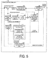
- FIG. 5 is a block diagram illustrating the configuration of the subpicture encoding unit 13a.
- the image coding apparatus 11 may be configured to include one subpicture encoding unit. In such a configuration, one subpicture encoding unit may sequentially encode subpictures.
- the subpicture encoding units 13a to 13n generate coded data for each subpicture. More detailed disclosure is as follows.
- the subpicture encoding unit 13a is configured to include a prediction image generation unit 101, a subtraction unit 102, a transform and quantization processing unit 103, an entropy encoding unit 104, an inverse quantization and inverse transform processing unit 105, an addition unit 106, a loop filter 107, a prediction parameter memory (a prediction parameter storage unit, a frame memory) 108, a reference picture memory (a reference image storage unit, a frame memory) 109, a coding parameter determination unit 110, and a prediction parameter encoding unit 111.
- the prediction parameter encoding unit 111 is configured to include an inter prediction parameter encoding unit 112 and an intra prediction parameter encoding unit 113.
- the prediction image generation unit 101 generates a prediction image P of a PU based on a pixel value of a reference block read from the reference picture memory, using a parameter input by the prediction parameter encoding unit.
- the prediction image generated by the prediction image generation unit 101 is output to the subtraction unit 102 and the addition unit 106.
- the subtraction unit 102 subtracts a signal value of the prediction image P of the PU input from the prediction image generation unit 101 from a pixel value of a corresponding PU of the image T to generate a residual signal.
- the subtraction unit 102 outputs the generated residual signal to the transform and quantization processing unit 103.
- the transform and quantization processing unit 103 performs a frequency transform on the residual signal input from the subtraction unit 102 to calculate a transform coefficient.
- the transform and quantization processing unit 103 quantizes the calculated transform coefficient to obtain a quantization coefficient.
- the transform and quantization processing unit 103 outputs the obtained quantization coefficient to the entropy encoding unit 104 and the inverse quantization and inverse transform processing unit 105.
- the quantization coefficient is input from the transform and quantization processing unit 103, and coding parameters are input from the prediction parameter encoding unit 111.
- input coding parameters include codes such as a reference picture index refIdxLX, a prediction vector index mvp_LX_idx, a difference vector mvdLX, a prediction mode predMode, and a merge index merge_idx.
- the entropy encoding unit 104 encodes header information such as an SPS, a PPS, a subpicture header SPH, a slice header SH, and the like.
- the entropy encoding unit 104 generates a slice header SH.
- the subpicture encoding unit 13a initializes a slice address that indicates a first CTU address of each slice included in the above-disclosed subpicture for each subpicture.
- the entropy encoding unit 104 generates a slice header that includes the slice address and includes the slice header in coded data for each subpicture.
- CTUs in a subpicture are scanned in order of raster scanning, and CTU addresses are assigned to the CTUs in the subpicture in the order of raster scanning.
- a first CTU address of the slice is assigned as a slice address SHaddr.
- slice addresses of slices included in a subpicture are initialized for each subpicture. In other words, for each subpicture, a first slice address of slices included in the subpicture starts from 0. In other words, in each subpicture, a first CTU address of a first slice (slice lead) is 0.
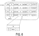
- FIG. 6 is a diagram illustrating a portion of a data structure of a coding stream Te' according to an embodiment of the present invention.
- the coding stream Te' includes a plurality of coding subpictures.
- Each coding subpicture includes one or a plurality of encoded slices.
- the slice address SHaddr of a first encoded slice in each coding subpicture is 0.
- slices having the same slice address may be distinguished based on subpictures to which the slices belong.
- information included in the subpicture header SPH may be used.
- the slice address (the address of the first CTU of the slice) is initialized for each subpicture. In other words, the slice address starts from 0 for each subpicture. For this reason, consecutive numbers are not assigned to slices belonging to different subpictures as slice addresses.
- slice addresses of subpictures do not need to be rewritten.
- slice addresses of an extracted area need to be rewritten from slice addresses corresponding to positions in the picture before extraction to slice addresses corresponding to positions in the picture after extraction.
- the slice address SHaddr of the first encoded slice in each coding subpicture is constantly 0 regardless of whether it is before or after extraction. For this reason, for the coding subpicture after extraction, slice addresses do not need to be rewritten.
- the slice addresses and the CTU addresses do not need to be corrected, and the subpictures can be cut out and combined with a low processing load.
- the entropy encoding unit 104 generates a coding stream by performing entropy coding of input quantization coefficients and coding parameters and outputs the generated coding stream to the outside.
- the inverse quantization and inverse transform processing unit 105 performs inverse quantization on the quantization coefficient input from the transform and quantization processing unit 103 to obtain a transform coefficient.
- the inverse quantization and inverse transform processing unit 105 performs an inverse frequency transform on the obtained transform coefficient to calculate a residual signal.
- the inverse quantization and inverse transform processing unit 105 outputs the calculated residual signal to the addition unit 106.
- the addition unit 106 adds a signal value of the prediction image P of the PU input from the prediction image generation unit 101 to a signal value of the residual signal input from the inverse quantization and inverse transform processing unit 105 for each pixel and generates a decoded image.
- the addition unit 106 stores the generated decoded image in the reference picture memory 109.
- the loop filter 107 applies a deblocking filter, Sample Adaptive Offset (SAO), and an Adaptive Loop Filter (ALF) to the decoded image generated by the addition unit 106.
- SAO Sample Adaptive Offset
- ALF Adaptive Loop Filter
- the prediction parameter memory 108 stores the prediction parameters generated by the coding parameter determination unit 110 for each picture and CU to be coded at a predetermined position.
- the reference picture memory 109 stores the decoded image generated by the loop filter 107 for each picture and CU to be coded at a predetermined position.
- the coding parameter determination unit 110 selects one set among a plurality of sets of coding parameters.
- a coding parameter refers to the previously disclosed prediction parameter or a parameter to be coded, the parameter being generated in association with the prediction parameter.
- the prediction image generation unit 101 generates the prediction image P of the PU by using each of the sets of the coding parameters.
- the coding parameter determination unit 110 calculates, for each of the plurality of sets, a cost value indicating the magnitude of an amount of information and a coding error.
- a cost value is, for example, the sum of a code amount and the value obtained by multiplying a coefficient ⁇ by a square error.
- the code amount is an amount of information of the coding stream Te obtained by performing entropy coding on a quantization error and a coding parameter.
- the square error is the sum of pixels for square values of residual values of residual signals calculated in the subtraction unit 102.
- the coefficient ⁇ is a preconfigured real number greater than a zero.
- the coding parameter determination unit 110 selects a set of coding parameters of which cost value calculated is a minimum value.
- the entropy encoding unit 104 outputs the selected set of coding parameters as the coding stream Te to the outside and does not output an unselected set of coding parameters.
- the coding parameter determination unit 110 stores the determined coding parameters in the prediction parameter memory 108.
- the prediction parameter encoding unit 111 derives a format for coding from parameters input from the coding parameter determination unit 110 and outputs the format to the entropy encoding unit 104.
- the derivation of the format for coding is, for example, to derive a difference vector from a motion vector and a prediction vector.
- the prediction parameter encoding unit 111 derives parameters necessary to generate a prediction image from parameters input from the coding parameter determination unit 110 and outputs the parameters to the prediction image generation unit 101.
- a parameter necessary to generate a prediction image is, for example, a motion vector of a subblock unit.
- the inter prediction parameter encoding unit 112 derives inter prediction parameters such as a difference vector based on the prediction parameters input from the coding parameter determination unit 110.
- the inter prediction parameter encoding unit 112 includes a configuration that is partly the same as a configuration in which an inter prediction parameter decoding unit 303 (see FIG. 13 and the like) to be disclosed subsequently derives inter prediction parameters.
- the intra prediction parameter encoding unit 113 derives a format for coding (for example, MPM_idx, rem_intra_luma_pred_mode, or the like) from the intra prediction mode IntraPredMode input from the coding parameter determination unit 110.
- a format for coding for example, MPM_idx, rem_intra_luma_pred_mode, or the like
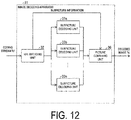
- FIG. 12 is a block diagram illustrating the configuration of the image decoding apparatus 31 according to an embodiment of the present invention.
- the image decoding apparatus 31 is configured to include an NAL decoding unit 32, subpicture decoding units 33a to 33n, and a picture combining unit 36.
- the NAL decoding unit 32 decodes a coding stream Te or a coding stream Te', which is encoded in units of network abstraction layer (NAL) units, input from the outside.
- the NAL decoding unit 32 transmits coding subpictures obtained by decoding the coding stream Te or the coding stream Te' to the subpicture decoding unit 33a to 33n.
- the NAL decoding unit 32 transmits subpicture information and the like to the picture combining unit 36.
- the subpicture information is information that indicates subpictures included in the coding stream Te or the coding stream Te', a size and a position of each of the subpictures, a size of a picture constituted by the subpictures, and the like.
- information of a subpicture parameter set SPPS and the like are included in the subpicture information.
- the subpicture decoding units 33a to 33n decode the subpicture headers SPH and the coding subpictures and transmit the decoded subpictures to the picture combining unit 36.
- the subpicture decoding units 33a to 33n perform a decoding process using the subpicture sequence as one independent video sequence and do not use the prediction information between subpicture sequences in time or in space in a case that the decoding process is performed. In other words, in the case of decoding a subpicture in a picture, the subpicture decoding units 33a to 33n do not use subpictures of other subpicture sequences.
- each of the subpicture decoding units 33a to 33n may perform a decoding process of a plurality of subpictures in parallel or may independently decode only one subpicture.
- a decoding process can be performed efficiently.
- the picture combining unit 36 refers to the subpicture information transmitted from the NAL decoding unit 32 and the subpictures decoded by the subpicture decoding units 33a to 33n and generates and outputs a decoded image Td.
- the image decoding apparatus 31 includes the subpicture decoding units 33a to 33n that decode subpicture coded data included in a coding stream Te' and the picture combining unit 36 that synthesizes a decoded image from the decoded subpictures.
- image data for each subpicture obtained by dividing a picture, a subpicture header SPH, and a subpicture parameter set SPPS (a combination picture parameter set) having information used for obtaining a picture (combined picture) by combining subpictures are included.
- the subpicture header SPH includes subpicture identification information used for distinguishing subpictures from each other and is generated for each subpicture.
- the subpicture parameter set SPPS includes one or a plurality of pieces of subpicture identification information. Details of the subpicture parameter set SPPS will be disclosed subsequently.
- the picture combining unit 36 synthesizes (generates) a decoded image of a picture (a combined picture) by referring to the subpicture parameter set SPPS included in the coding stream Te' and decoded images of subpictures.
- the image decoding apparatus 31 can use a subpicture parameter set representing a combination of subpictures corresponding to a partial area of a picture, which is designated by a user, and synthesize subpictures corresponding to the partial area. In other words, the image decoding apparatus 31 can generate an image desired by a user.
- a slice header is included in the coding stream Te'.
- a slice address indicating a first CTU address of a slice included in a subpicture is included in the slice header. This slice address is initialized for each subpicture.
- the subpicture decoding units 33a to 33n generate decoded images of subpictures by referring to the slice header including slice addresses included in the coded data.
- the slice address of a subpicture is initialized for each subpicture.
- a slice address (a first CTU address of a slice) included in a subpicture starts from 0 for each subpicture. For this reason, consecutive numbers are not assigned to slices belonging to different subpictures as slice addresses.
- a slice header and slice data are as follows.
- the newly generated coded data does not include coded data of all the subpictures.
- missing (skipping) of a slice address (CTU address) does not occur.
- occurrence of errors in the image decoding apparatus 31 that may be caused by missing (skipping) a slice address can be avoided.
- FIG. 13 is a block diagram illustrating the configuration of a subpicture decoding unit 33a.
- the subpicture decoding unit 33a is configured to include an entropy decoding unit 301, a prediction parameter decoding unit 302, a loop filter 305, a reference picture memory 306, a prediction parameter memory 307, a prediction image generation unit 308, an inverse quantization and inverse transform processing unit 311, and an addition unit 312.
- the prediction parameter decoding unit 302 includes an inter prediction parameter decoding unit 303 and an intra prediction parameter decoding unit 304.
- the prediction image generation unit 308 includes an inter prediction image generation unit 309 and an intra prediction image generation unit 310.
- the entropy decoding unit 301 performs entropy decoding on a coding subpicture, thereby performing decoding with individual codes (syntax elements) separated from each other. As separated codes, there are prediction information used for generating a prediction image, residual information used for generating a differential image, and the like.
- the entropy decoding unit 301 outputs a part of the separated codes to the prediction parameter decoding unit 302.
- a part of the separated codes includes a prediction mode predMode, a PU split mode part_mode, a merge flag merge_flag, a merge index merge idx, an inter prediction indicator inter_pred_idc, a reference picture index refIdxLX, a prediction vector index mvp_LX_idx, and a difference vector mvdLX.
- Which code is to be decoded is controlled based on an indication of the prediction parameter decoding unit 302.
- the entropy decoding unit 301 outputs quantization coefficients to the inverse quantization and inverse transform processing unit 311.
- quantization coefficients are coefficients obtained by performing a frequency transform such as a Discrete Cosine Transform (DCT), a Discrete Sine Transform (DST), or a Karyhnen Loeve Transform (KLT) on residual signals to quantize the signals in coding processing.
- a frequency transform such as a Discrete Cosine Transform (DCT), a Discrete Sine Transform (DST), or a Karyhnen Loeve Transform (KLT)
- the inter prediction parameter decoding unit 303 decodes an inter prediction parameter with reference to a prediction parameter stored in the prediction parameter memory 307, based on a code input from the entropy decoding unit 301.
- the inter prediction parameter decoding unit 303 outputs a decoded inter prediction parameter to the prediction image generation unit 308, and also stores the decoded inter prediction parameter in the prediction parameter memory 307.
- the intra prediction parameter decoding unit 304 decodes an intra prediction parameter with reference to a prediction parameter stored in the prediction parameter memory 307, based on a code input from the entropy decoding unit 301.
- the intra prediction parameter is a parameter used in processing to predict a CU in one picture, for example, an intra prediction mode IntraPredMode.
- the intra prediction parameter decoding unit 304 outputs a decoded intra prediction parameter to the prediction image generation unit 308, and also stores the decoded intra prediction parameter in the prediction parameter memory 307.
- the loop filter 305 applies a filter such as a deblocking filter, a Sample Adaptive Offset (SAO), and an Adaptive Loop Filter (ALF) on a decoded image of a CU generated by the addition unit 312.
- a filter such as a deblocking filter, a Sample Adaptive Offset (SAO), and an Adaptive Loop Filter (ALF) on a decoded image of a CU generated by the addition unit 312.
- the reference picture memory 306 stores a decoded image of the CU generated by the addition unit 312 at a predetermined position for each subpicture that is a decoding target and each CU.
- the prediction parameter memory 307 stores a prediction parameter at a predetermined position for each picture that is a decoding target, and a prediction unit (or a subblock, a fixed size block, or a pixel). Specifically, the prediction parameter memory 307 stores an inter prediction parameter decoded by the inter prediction parameter decoding unit 303, an intra prediction parameter decoded by the intra prediction parameter decoding unit 304 and a prediction mode predMode separated by the entropy decoding unit 301.
- stored inter prediction parameters include a prediction list use flag predFlagLX (inter prediction indicator inter_pred_idc), a reference picture index refIdxLX, and a motion vector mvLX.
- the prediction image generation unit 308 receives input of a prediction mode predMode from the entropy decoding unit 301 and a prediction parameter from the prediction parameter decoding unit 302. In addition, the prediction image generation unit 308 reads a reference picture from the reference picture memory 306. The prediction image generation unit 308 generates a prediction image of a PU or a subblock by using input prediction parameters and the read reference picture (a reference picture block) in a prediction mode indicated by the prediction mode predMode.
- the inter prediction image generation unit 309 generates a prediction image of a PU or a subblock through an inter prediction using inter prediction parameters input from the inter prediction parameter decoding unit 303 and the read reference picture (reference picture block).
- the inter prediction image generation unit 309 For a reference picture list (an L0 list or an L1 list) of which the prediction list use flag predFlagLX is 1, the inter prediction image generation unit 309 reads a reference picture block that is present at a position indicated by a motion vector mvLX with reference to the PU, which is a decoding target, in the reference picture indicated by the reference picture index refIdxLX from the reference picture memory 306.
- the inter prediction image generation unit 309 performs a prediction based on a read reference picture block and generates a prediction image of the PU.
- the inter prediction image generation unit 309 outputs the generated prediction image of the PU to the addition unit 312.
- the reference picture block is a set of pixels (generally referred to as a block due to its rectangular shape) of a reference picture and is an area to be used for generating a prediction image of a PU or a subblock.
- the intra prediction image generation unit 310 performs an intra prediction by using an intra prediction parameter input from the intra prediction parameter decoding unit 304 and a read reference picture.
- the intra prediction image generation unit 310 outputs the generated prediction image of the PU to the addition unit 312.
- the inverse quantization and inverse transform processing unit 311 performs inverse quantization on a quantization coefficient input from the entropy decoding unit 301 to calculate a transform coefficient.
- the inverse quantization and inverse transform processing unit 311 performs an inverse frequency transform such as an inverse DCT, an inverse DST, or an inverse KLT on the calculated transform coefficient to calculate a residual signal.
- the inverse quantization and inverse transform processing unit 311 outputs the calculated residual signal to the addition unit 312.
- the addition unit 312 generates a decoded image of a PU by adding a prediction image of the PU input from the inter prediction image generation unit 309 or the intra prediction image generation unit 310 to a residual signal input from the inverse quantization and inverse transform processing unit 311 for each pixel.
- the addition unit 312 stores the generated decoded image of a PU in the reference picture memory 306, and outputs a decoded image Td where the generated decoded image of the PU is integrated for each picture to the outside.
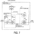
- FIG. 7 is a block diagram illustrating the configuration of a coding stream extraction apparatus 51.
- the coding stream extraction apparatus 51 generates a coding stream Te' (output coded data) from the coding stream Te (input coded data) generated by the image coding apparatus 11. As illustrated in FIG. 7 , the coding stream extraction apparatus 51 includes a subpicture ID deriving unit 511, an entropy decoding unit 512, and an entropy encoding unit (an encoding unit) 513.
- the subpicture ID deriving unit 511 receives control information that indicates a partial area of the entire picture selected by a user.
- the subpicture ID deriving unit 511 may be configured to be able to receive the area designated by a user's selection operation from the image decoding apparatus 31 or the image display apparatus 41.
- the image decoding apparatus 31 or the image display apparatus 41 outputs the control information disclosed previously to the subpicture ID deriving unit 511.
- the subpicture ID deriving unit 511 derives an ID of a subpicture including the area from the control information disclosed previously.
- FIG. 8 is a diagram illustrating of an area R1 selected by a user in a whole picture .
- upper left coordinates of the area R1 are P1 (xReg, yReg).
- a width of the area R1 is wReg
- a height of the area R1 is hReg.
- the control information indicates the upper left coordinates P1(xReg, yReg) of the area Rl, the width wReg of the area R1, and the height hReg of the area R1.
- the subpicture ID deriving unit 511 derives a subpicture ID including the area selected by the user based on the control information received from the image decoding apparatus 31 or the image display apparatus 41. For example, in the example illustrated in FIG. 8 , the area R1 selected by the user is included in subpictures 2 and 3. For this reason, the subpicture ID deriving unit 511 derives subpicture IDs of the subpictures 2 and 3.
- the subpicture ID deriving unit 511 outputs the derived subpicture IDs to the coding stream extraction unit 5123 of the entropy decoding unit 512 and the header encoding unit 5131 of the entropy encoding unit 513.
- the image decoding apparatus 31 or the image display apparatus 41 that has received a user's selection operation may be configured to derive subpicture IDs of subpictures including an area selected by the user. In such a case, the image decoding apparatus 31 or the image display apparatus 41 transmits the subpicture IDs to the coding stream extraction apparatus 51. For this reason, the subpicture ID deriving unit 511 is unnecessary.
- the entropy decoding unit 512 decodes coded data of a part of the coding streams Te. As illustrated in FIG. 7 , the entropy decoding unit 512 includes a header decoding unit 5121 and a coding stream extraction unit 5123.
- the header decoding unit 5121 decodes a part of header information (header information for the SPPS) that is necessary for generation of the subpicture parameter set SPPS in the coded data input from the image coding apparatus 11.
- the header decoding unit 5121 outputs a coding stream of the SPS, the PPS and the SPH and subsequent items to the coding stream extraction unit 5123.
- the header decoding unit 5121 outputs the header information for the SPPS that has been decoded to the header encoding unit 5131.
- the coding stream extraction unit 5123 extracts a coding stream (SPH and coded data of the SPH and subsequent items) of a subpicture corresponding to the received subpicture ID. Alternatively, a coding stream of a subpicture that does not correspond to the subpicture ID is deleted from the coding stream Te. The coding stream extraction unit 5123 outputs the header information and the coding stream of the extracted subpicture to a coding stream combining unit 5133 of the entropy encoding unit 513.
- the entropy encoding unit 513 encodes the coding stream Te'. As illustrated in FIG. 7 , the entropy encoding unit 513 includes a header encoding unit 5131 and the coding stream combining unit 5133.
- the header encoding unit 5131 (a subpicture parameter set generation unit) generates a subpicture parameter set SPPS in accordance with a received subpicture ID.
- the header encoding unit 5131 encodes the subpicture parameter set SPPS including a list of subpicture IDs.
- the header encoding unit 5131 outputs the coding subpicture parameter set SPPS to the coding stream combining unit 5133.
- the coding stream combining unit 5133 generates coded data that includes a subpicture parameter set SPPS including one or a plurality of pieces of subpicture identification information (subpicture IDs) and image data for each of subpictures corresponding to the above-disclosed subpicture IDs.
- the coding stream combining unit 5133 generates the coding stream Te' as follows: In other words, the header information received from the coding stream extraction unit 5123 and the coding stream of each of the subpictures and the subpicture parameter set SPPS received from the header encoding unit 5131 are combined.
- the configuration of the coding stream extraction apparatus 51 may be a configuration illustrated in FIG. 17.
- FIG. 17 is a block diagram illustrating the configuration of a coding stream extraction apparatus 51a according to an embodiment of the present invention.
- the coding stream extraction apparatus 51a illustrated in FIG. 17 can replace the coding stream extraction apparatus 51 illustrated in FIG. 7 .
- the coding stream extraction apparatus 51a includes a subpicture extraction unit 514 and an SPPS generation unit 515. It is assumed that a subpicture ID derived from the control information by an external device is input to the coding stream extraction apparatus 51a.
- the subpicture extraction unit 514 extracts a coding stream (the SPH and the coded data of the SPH and subsequent items) of a subpicture corresponding to the received subpicture ID from the coding stream Te. Alternatively, a coding stream of a subpicture that does not correspond to the subpicture ID is deleted from the coding stream Te.
- the SPPS generation unit 515 generates a subpicture parameter set SPPS from the received subpicture ID. Then, the SPPS generation unit 515 generates a coding stream Te' by combining the SPPS and the coding stream of the subpicture extracted by the subpicture extraction unit 514.
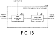
- the configuration of the coding stream extraction apparatus 51 may be a configuration illustrated in FIG. 18.
- FIG. 18 is a block diagram illustrating the configuration of a coding stream extraction apparatus 51b according to an embodiment of the present invention.
- the coding stream extraction apparatus 51b illustrated in FIG. 18 can replace the coding stream extraction apparatus 51 illustrated in FIG. 7 .
- the coding stream extraction apparatus 51b includes an SPPS extraction unit 516 and a subpicture extraction unit 517. It is assumed that a subpicture ID derived from the control information by an external device is input to the coding stream extraction apparatus 51b. Differently from the coding stream extraction apparatuses illustrated in FIGS.
- a plurality of subpicture parameter sets are included in advance in a coding stream Te input to the coding stream extraction apparatus 51b illustrated in FIG. 18 .
- the SPPS extraction unit 516 extracts an SPPS corresponding to the received subpicture ID from the coding stream Te. Alternatively, the SPPS extraction unit 516 deletes an SPPS that does not correspond to the received subpicture ID from the coding stream Te. Similar to the subpicture extraction unit 514, the subpicture extraction unit 517 extracts coded data of a subpicture corresponding to the received subpicture ID. In addition, the subpicture extraction unit 517 generates a coding stream Te' by combining the SPPS output by the SPPS extraction unit 516 and coded data of the extracted subpicture.
- FIG. 19 is a block diagram illustrating the configuration of a coding stream extraction apparatus 51c according to an embodiment of the present invention.
- the coding stream extraction apparatus 51c illustrated in FIG. 19 can replace the coding stream extraction apparatus 51 illustrated in FIG. 7 .
- the coding stream extraction apparatus 51c is composed of a subpicture extraction unit 514.
- the subpicture extraction unit 514 extracts a coding stream of a subpicture corresponding to the received subpicture ID.
- a coding stream of a subpicture that does not correspond to the subpicture ID is deleted from the coding stream Te. Then, a coding stream Te' is generated.
- FIG. 4 is a diagram illustrating an example of a picture having subpictures according to an embodiment of the present invention as constituent units.
- FIG. 4 illustrates a relation between a picture and a subpicture according to an embodiment of the present invention.
- FIG. 4 illustrates an example in which there are three pictures including picture 1, picture 2, and picture 3 in coded data.
- the picture 1 is composed of subpictures 0 to 7, and the picture 2 is composed of subpictures 0, 1, 4, and 5.
- the picture 2 is composed of subpictures 3 and 7,
- Information indicating which subpictures a specific picture is composed of is transmitted and accumulated using a subpicture parameter set SPPS.
- a picture is disclosed for each subpicture parameter set SPPS, and N pictures are disclosed in a case that N subpicture parameter sets SPPS are included in the coded data.
- a subpicture may be composed of one slice, or, as illustrated in FIG. 4 , a subpicture may be composed of a plurality of sub-areas (for example, tiles or slices).
- the subpicture parameter set SPPS generated by the header encoding unit 5131 includes information indicating which subpictures a picture included in the coding stream Te' is composed of. More specifically, the subpicture parameter set SPPS may include information used for identifying subpictures constituting the picture (subpicture identifiers). For example, the subpicture parameter set SPPS may include a list of the subpicture identifiers included _subpic_id[] indicating subpictures. In addition, the subpicture parameter set SPPS may include a size of each subpicture subpic size and a size of a picture pic_size composed of subpictures.
- the NAL decoding unit 32 may decode the information (the subpicture identifier) used for identifying a subpicture constituting the picture, the picture size, and the subpicture size from the coding stream Te'.
- the header encoding unit 5131 may encode the information (the subpicture identifier) used for identifying a subpicture constituting the picture, the picture size, and the subpicture size.
- each of the picture 1, the picture 2, and the picture 3 illustrated in FIG. 4 are disclosed using subpicture parameter sets SPPS1, SPPS2, and SPPS3, and the subpicture parameter set SPPS will be disclosed subsequently.
- the subpicture parameter set SPPS1 corresponding to the picture 1 illustrated in FIG. 4 includes the following information.
- pic_size 4096x2048
- pic_size indicates the size of the picture 1.
- subpic_size indicates the size of a subpicture.
- the image decoding apparatus 31 may decode coded data corresponding to the partial area disclosed previously by referring to the subpicture size and the picture size included in the subpicture parameter set SPPS.
- the subpicture size may be restricted to be the same for all the subpictures.
- included_subpic_id[] indicates a list of subpicture identification information (subpicture IDs) of subpictures constituting a coded picture transmitted using the coding stream Te'. This subpicture ID may be output by the subpicture ID deriving unit 511.
- the subpicture parameter set SPPS1 designates subpictures corresponding to the subpicture identification information 0, 1, 2, 3, 4, 5, 6, and 7.
- the subpicture identification information of the subpicture may be designated using the subpicture header.
- the subpicture parameter set SPPS2 designates the subpictures 0, 1, 4, and 5.
- pic_size 2048x2048.
- included_subpic_id[] ⁇ 3, 7 ⁇ .
- the subpicture parameter set SPPS3 designates subpictures 3 and 7.
- pic_size 1024x2048.
- FIG. 9 is a schematic diagram illustrating an example of the configuration of a coding stream Te' according to an embodiment of the present invention.
- a slice header SH includes a PPS id of a corresponding picture parameter set PPS.
- the slice header SH has a link to the corresponding picture parameter set PPS.
- the picture parameter set PPS includes an SPS id of the corresponding sequence parameter set SPS.
- the picture parameter set PPS has a link to the corresponding sequence parameter set SPS.
- one slice may be associated with a plurality of subpicture parameter sets SPPS.
- a specific area a set of slices or subpictures
- SPPS subpicture parameter sets
- the subpicture parameter set SPPS designates a corresponding subpicture header SPH.
- the subpicture parameter set SPPS has a link to a subpicture (included_subpic_id[] disclosed previously).
- the definition of the picture (the subpicture) can be rewritten by only rewriting the link of the subpicture parameter set SPPS, in other words, included_subpic_id[].
- slices do not need to be rewritten.
- a slice following the subpicture header SPH is a slice that belongs to the subpicture designated by the SPPS.
- a subpicture parameter set SPPS1 corresponding to the picture 1 designates a subpicture header SPH0 corresponding to the subpicture 0 and a subpicture header SPH3 corresponding to the subpicture 3.
- the subpicture parameter set SPPS2 corresponding to the picture 2 designates a subpicture header SPH0 corresponding to the subpicture 0.
- the subpicture parameter set SPPS2 does not designate the subpicture header SPH3 corresponding to the subpicture 3.
- the subpicture parameter set SPPS3 corresponding to the picture 3 does not designate the subpicture header SPH0 corresponding to the subpicture 0.
- the subpicture parameter set SPPS3 designates a subpicture header SPH3 corresponding to the subpicture 3.
- the subpicture parameter set SPPS may be configured to be transmitted by the NAL unit.
- nal_unit_type of nal_unit_header() may be disclosed as follows.
- the coding stream extraction apparatus 51 generates a subpicture parameter set SPPS including one or a plurality of pieces of subpicture identification information (subpicture IDs).
- the coding stream extraction apparatus 51 can generate a subpicture parameter set indicating a combination of subpictures included in the coding stream Te'. For this reason, coded data corresponding to a partial area of input coded data designated by the user can be newly generated with a small amount of processing.
- the coding stream extraction apparatus 51 can generate a subpicture parameter set indicating a combination of subpictures corresponding to the partial area.
- the image decoding apparatus 31 can decode only an area desired by a user and display video having a small delay due to transmission and processing in the image display apparatus 41.
- the coding stream extraction apparatus 51 transmits required minimum coded data and can inhibit a load applied to traffics in a transmission path to be minimal.
- the coding stream extraction apparatus 51 generates coded data by combining extracted subpictures, slice addresses and CTU addresses do not need to be corrected, and subpictures can be cut out and combination with a small processing load.
- a subpicture parameter set SPPS according to this modified example includes at least one of a subpicture profile and a level.
- the header encoding unit 5131 generates a profile disclosed using a set of coding tools such that it is included in the subpicture parameter set disclosed previously.
- the header encoding unit 5131 generates a level indicating an image size such that it is included in the subpicture parameter set disclosed previously.
- profiles and level information are configured by referring to the header information for the SPPS and the like output by the header decoding unit 5121.
- the header encoding unit 5131 may include information indicating the subpicture level and the profile as disclosed subsequently in the above-disclosed subpicture parameter sets SPPS1 to SPPS3.
- a profile disclosed by a set of coding tools necessary for decoding subpictures can be presented for the image decoding apparatus 31.
- the image decoding apparatus 31 can indicate a level indicating an image size required for decoding a subpicture.
- an image decoding apparatus having a decoding capacity lower than an image decoding apparatus capable of decoding an entire picture by referring to the profile and the level disclosed previously, it can be determined whether or not the decoding of a picture or a subpicture can be handled.
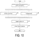
- FIG. 10 is a flowchart illustrating a method of an example of the flow of the process of generating a coding stream Te'.
- the subpicture ID deriving unit 511 derives IDs of subpictures including an area designated by a user from control information corresponding to the area designated by the user (S1). As illustrated in FIG. 4 , a picture 3 is composed of subpictures 3 and 7. In a case that an area included in the picture 3 is designated by a user, the subpicture ID deriving unit 511 derives subpicture IDs of the subpicture 3 and the subpicture 7.
- the coding stream extraction unit 5123 extracts coded data of subpictures corresponding to the subpicture IDs received from the subpicture ID deriving unit 511 (S2).
- the header encoding unit 5131 In parallel with S2, the header encoding unit 5131 generates subpicture parameter sets SPPS in accordance with the received subpicture IDs and the header information for the SPPS (S3).
- the coding stream combining unit 5133 generates a coding stream Te' by combining the header information, the coding stream of each subpicture, and the subpicture parameter sets SPPS (S4).
- the coding stream combining unit 5133 outputs the generated coding stream Te' to the image decoding apparatus 31 (S5).
- FIG. 11 is a diagram illustrating a coding stream Te' generated by a coding stream extraction apparatus 51 according to an embodiment of the present invention.
- FIG. 11 illustrates an example of a coding stream Te' generated by the coding stream extraction apparatus 51 in a case that a user designates an area included in the picture 3 illustrated in FIG. 4 .
- the coding stream Te' includes a sequence parameter set SPS and a picture parameter set PPS, a subpicture parameter set SPPS3 corresponding to the picture 3; a subpicture header SPH3 corresponding to subpicture 3, a coding subpicture 3 (SPICT3), a subpicture header SPH7 corresponding to a subpicture 7, and the subpicture 7 (SPICT7).
- Parts of the image coding apparatus 11 and the image decoding apparatus 31 according to the above-disclosed embodiments for example, the entropy decoding unit 301, the prediction parameter decoding unit 302, the loop filter 305, the prediction image generation unit 308, the inverse quantization and inverse transform processing unit 311, the addition unit 312, the prediction image generation unit 101, the subtraction unit 102, the transform and quantization processing unit 103, the entropy encoding unit 104, the inverse quantization and inverse transform processing unit 105, the loop filter 107, the coding parameter determination unit 110, and the prediction parameter encoding unit 111, may be realized by a computer.
- this configuration may be realized by recording a program for realizing such control functions on a computer-readable recording medium and causing a computer system to read the program recorded on the recording medium for execution.
- the "computer system” mentioned here refers to a computer system built into either the image coding apparatus 11 or the image decoding apparatus 31 and is assumed to include an OS and hardware components such as a peripheral apparatus.
- a "computer-readable recording medium” refers to a portable medium such as a flexible disk, a magneto-optical disk, a ROM, a CD-ROM, and the like, and a storage device such as a hard disk built into the computer system.
- the "computer-readable recording medium” may include a medium that dynamically retains a program for a short period of time, such as a communication line in a case that the program is transmitted over a network such as the Internet or over a communication line such as a telephone line, and may also include a medium that retains the program for a fixed period of time, such as a volatile memory included in the computer system functioning as a server or a client in such a case.
- the above-disclosed program may be one for realizing some of the above-disclosed functions, and also may be one capable of realizing the above-disclosed functions in combination with a program already recorded in a computer system.
- a part or all of the image coding apparatus 11 and the image decoding apparatus 31 may be realized as an integrated circuit such as a Large-Scale Integration (LSI).
- LSI Large-Scale Integration
- Each function block of the image coding apparatus 11 and the image decoding apparatus 31 may be individually realized as processors, or part or all may be integrated into processors.
- a circuit integration technique is not limited to the LSI, and may be realized with a dedicated circuit or a general-purpose processor. Furthermore, in a case that advances in semiconductor technology lead to the advent of a circuit integration technology that replaces an LSI, an integrated circuit based on the circuit integration technology may be used.
- the previously disclosed image coding apparatus 11 and the image decoding apparatus 31 can be utilized being installed to various apparatuses performing transmission, reception, recording, and reproduction of videos.
- the video may be a natural video imaged by camera or the like, or may be an artificial video (including CG and GUI) generated by computer or the like.
- the previously disclosed image coding apparatus 11 and the image decoding apparatus 31 can be utilized for transmission and reception of videos.
- FIG. 14(a) is a block diagram illustrating a configuration of a transmitting apparatus PROD_A installed with the image coding apparatus 11.
- the transmitting apparatus PROD_A includes an encoding unit PROD_A1 which obtains coded data by coding videos, a modulation unit PROD_A2 which obtains modulation signals by modulating carrier waves with the coded data obtained by the encoding unit PROD_A1, and a transmitting unit PROD_A3 which transmits the modulation signals obtained by the modulation unit PROD_A2.
- the previously disclosed image coding apparatus 11 is utilized as the encoding unit PROD_A1.
- the transmitting apparatus PROD_A may further include a camera PROD_A4 that images videos, a recording medium PROD_A5 that records videos, an input terminal PROD_A6 for inputting videos from the outside, and an image processing unit A7 which generates or processes images, as supply sources of videos to be input into the encoding unit PROD_A1.
- a camera PROD_A4 that images videos
- a recording medium PROD_A5 that records videos
- an input terminal PROD_A6 for inputting videos from the outside
- an image processing unit A7 which generates or processes images, as supply sources of videos to be input into the encoding unit PROD_A1.
- the recording medium PROD_A5 may record videos which are not coded or may record videos coded in a coding scheme for recording different from a coding scheme for transmission.
- a decoding unit (not illustrated) to decode coded data read from the recording medium PROD A5 according to the coding scheme for recording may be present between the recording medium PROD_A5 and the encoding unit PROD_A1.
- FIG. 14(b) is a block diagram illustrating a configuration of a receiving apparatus PROD_B installed with the image decoding apparatus 31.
- the receiving apparatus PROD_B includes a receiving unit PROD_B1 that receives modulation signals, a demodulation unit PROD B2 that obtains coded data by demodulating the modulation signals received by the receiving unit PROD_B1, and a decoding unit PROD_B3 that obtains videos by decoding the coded data obtained by the demodulation unit PROD_B2.
- the previously disclosed image decoding apparatus 31 is utilized as the decoding unit PROD_B3.
- the receiving apparatus PROD_B may further include a display PROD_B4 that displays videos, a recording medium PROD B5 for recording the videos, and an output terminal PROD_B6 for outputting the videos to the outside, as supply destinations of the videos to be output by the decoding unit PROD_B3.
- a display PROD_B4 that displays videos
- a recording medium PROD B5 for recording the videos
- an output terminal PROD_B6 for outputting the videos to the outside, as supply destinations of the videos to be output by the decoding unit PROD_B3.
- the recording medium PROD_B5 may record videos which are not coded, or may record videos which are coded in a coding scheme for recording different from a coding scheme for transmission.
- an encoding unit (not illustrated) that encodes videos acquired from the decoding unit PROD_B3 according to the coding scheme for recording may be present between the decoding unit PROD B3 and the recording medium PROD B5.
- a transmission medium for transmitting the modulation signals may be a wireless medium or may be a wired medium.
- a transmission mode in which the modulation signals are transmitted may be a broadcast (here, which indicates a transmission mode in which a transmission destination is not specified in advance) or may be a communication (here, which indicates a transmission mode in which a transmission destination is specified in advance). That is, the transmission of the modulation signals may be realized by any of a wireless broadcast, a wired broadcast, a wireless communication, and a wired communication.
- a broadcasting station e.g., broadcasting equipment
- a transmitting apparatus PROD_A/receiving apparatus PROD_B for transmitting and/or receiving the modulation signals in the wireless broadcast.
- a broadcasting station e.g., broadcasting equipment
- a broadcasting station e.g., television receivers
- the transmitting apparatus PROD_A/receiving apparatus PROD B for transmitting and/or receiving the modulation signals in the wired broadcast.
- a server e.g., workstation
- client e.g., television receiver, personal computer, smartphone
- VOD Video On Demand
- the transmitting apparatus PROD_A/receiving apparatus PROD B for transmitting and/or receiving the modulation signals in communication
- personal computers include a desktop PC, a laptop PC, and a tablet PC.
- smartphones also include a multifunctional mobile telephone terminal.
- a client of a video hosting service has a function of coding video imaged with a camera and uploading the video to a server, in addition to a function of decoding coded data downloaded from a server and displaying on a display. Therefore, the client of the video hosting service functions as both the transmitting apparatus PROD_A and the receiving apparatus PROD_B.
- previously disclosed image coding apparatus 11 and the image decoding apparatus 31 can be utilized for recording and reproduction of videos.
- FIG. 15(a) is a block diagram illustrating a configuration of a recording apparatus PROD_C installed with the previously disclosed image coding apparatus 11.
- the recording apparatus PROD C includes an encoding unit PROD_C1 that obtains coded data by coding video, and a writing unit PROD_C2 that writes the coded data obtained by the encoding unit PROD_C1 in a recording medium PROD_M.
- the previously disclosed image coding apparatus 11 is utilized as the encoding unit PROD_C1.
- the recording medium PROD M may be (1) a type of recording medium built in the recording apparatus PROD C such as Hard Disk Drive (HDD) or Solid State Drive (SSD), may be (2) a type of recording medium connected to the recording apparatus PROD_C such as an SD memory card or a Universal Serial Bus (USB) flash memory, and may be (3) a type of recording medium loaded in a drive apparatus (not illustrated) built in the recording apparatus PROD_C such as Digital Versatile Disc (DVD) or Blu-ray Disc (BD: trade name).
- HDD Hard Disk Drive
- SSD Solid State Drive
- a type of recording medium connected to the recording apparatus PROD_C such as an SD memory card or a Universal Serial Bus (USB) flash memory
- USB Universal Serial Bus
- the recording apparatus PROD_C may further include a camera PROD_C3 that images video, an input terminal PROD C4 for inputting the video from the outside, a receiving unit PROD_CS for receiving the video, and an image processing unit PROD_C6 that generates or processes images, as supply sources of the video input into the encoding unit PROD_C1.
- a camera PROD_C3 that images video
- an input terminal PROD C4 for inputting the video from the outside
- a receiving unit PROD_CS for receiving the video
- an image processing unit PROD_C6 that generates or processes images, as supply sources of the video input into the encoding unit PROD_C1.
- the receiving unit PROD_C5 may receive video which is not coded, or may receive coded data coded in a coding scheme for transmission different from the coding scheme for recording. In the latter case, a decoding unit for transmission (not illustrated) that decodes coded data coded in the coding scheme for transmission may be present between the receiving unit PROD_C5 and the encoding unit PROD_C1.
- Examples of such recording apparatus PROD_C include, for example, a DVD recorder, a BD recorder, a Hard Disk Drive (HDD) recorder, and the like (in this case, the input terminal PROD_C4 or the receiving unit PROD_C5 is the main supply source of videos).
- a camcorder in this case, the camera PROD_C3 is the main supply source of videos
- a personal computer in this case, the receiving unit PROD_C5 or the image processing unit C6 is the main supply source of videos
- a smartphone in this case, the camera PROD C3 or the receiving unit PROD_C5 is the main supply source of videos
- the recording apparatus PROD_C is an example of the recording apparatus PROD_C as well.
- FIG. 15(b) is a block diagram illustrating a configuration of a reconstruction apparatus PROD D installed with the previously disclosed image decoding apparatus 31.
- the reconstruction apparatus PROD_D includes a reading unit PROD_D1 which reads coded data written in the recording medium PROD M, and a decoding unit PROD_D2 which obtains video by decoding the coded data read by the reading unit PROD_D1.
- the previously disclosed image decoding apparatus 31 is utilized as the decoding unit PROD_D2.
- the recording medium PROD_M may be (1) a type of recording medium built in the reconstruction apparatus PROD_D such as HDD or SSD, may be (2) a type of recording medium connected to the reconstruction apparatus PROD_D such as an SD memory card or a USB flash memory, and may be (3) a type of recording medium loaded in a drive apparatus (not illustrated) built in the reconstruction apparatus PROD_D such as a DVD or a BD.
- the reconstruction apparatus PROD_D may further include a display PROD_D3 that displays video, an output terminal PROD_D4 for outputting the video to the outside, and a transmitting unit PROD_D5 that transmits the video, as the supply destinations of the video to be output by the decoding unit PROD_D2.
- a display PROD_D3 that displays video
- an output terminal PROD_D4 for outputting the video to the outside
- a transmitting unit PROD_D5 that transmits the video, as the supply destinations of the video to be output by the decoding unit PROD_D2.
- the transmitting unit PROD_D5 may transmit video which is not coded or may transmit coded data coded in the coding scheme for transmission different from a coding scheme for recording.
- an encoding unit (not illustrated) that codes video in the coding scheme for transmission may be present between the decoding unit PROD D2 and the transmitting unit PROD_D5.
- Examples of the reconstruction apparatus PROD_D include, for example, a DVD player, a BD player, an HDD player, and the like (in this case, the output terminal PROD_D4 to which a television receiver, and the like are connected is the main supply destination of videos).
- a television receiver (in this case, the display PROD_D3 is the main supply destination of videos), a digital signage (also referred to as an electronic signboard or an electronic bulletin board, and the like, and the display PROD_D3 or the transmitting unit PROD_D5 is the main supply destination of videos), a desktop PC (in this case, the output terminal PROD_D4 or the transmitting unit PROD D5 is the main supply destination of videos), a laptop or tablet PC (in this case, the display PROD_D3 or the transmitting unit PROD_D5 is the main supply destination of videos), a smartphone (in this case, the display PROD_D3 or the transmitting unit PROD_D5 is the main supply destination of videos), or the like is an example of the reconstruction apparatus PROD_D.
- Each block of the previously disclosed image decoding apparatus 31 and the image coding apparatus 11 may be realized as a hardware by a logical circuit formed on an integrated circuit (IC chip), or may be realized as a software using a Central Processing Unit (CPU).
- IC chip integrated circuit
- CPU Central Processing Unit
- each of the above-disclosed apparatuses include a CPU that executes a command of a program to implement each of functions, a Read Only Memory (ROM) that stores the program, a Random Access Memory (RAM) to which the program is loaded, and a storage apparatus (recording medium), such as a memory, that stores the program and various kinds of data.
- ROM Read Only Memory
- RAM Random Access Memory
- recording medium such as a memory
- an objective of the embodiments of the present invention can be achieved by supplying, to each of the apparatuses, the recording medium that records, in a computer readable form, program codes of a control program (executable program, intermediate code program, source program) of each of the apparatuses that is software for realizing the disclosed functions and by reading and executing, by the computer (or a CPU or a MPU), the program codes recorded in the recording medium.
- a control program executable program, intermediate code program, source program
- the recording medium for example, tapes including a magnetic tape, a cassette tape and the like, discs including a magnetic disc such as a floppy (trade name) disk/a hard disk and an optical disc such as a Compact Disc Read-Only Memory (CD-ROM)/Magneto-Optical disc (MO disc)/Mini Disc (MD)/Digital Versatile Disc (DVD)/CD Recordable (CD-R)/Blu-ray Disc (trade name), cards such as an IC card (including a memory card)/an optical card, semiconductor memories such as a mask ROM/Erasable Programmable Read-Only Memory (EPROM)/Electrically Erasable and Programmable Read-Only Memory (EEPROM: trade name)/a flash ROM, logical circuits such as a Programmable Logic Device (PLD) and a Field Programmable Gate Array (FPGA), or the like can be used.
- CD-ROM Compact Disc Read-Only Memory
- MO disc Magnetic Disc Read-Only Memory
- each of the apparatuses is configured to be connectable with a communication network, and the program codes may be supplied through the communication network.
- the communication network is required to be capable of transmitting the program codes, but is not limited to a particular communication network.
- the Internet an intranet, an extranet, a Local Area Network (LAN), an Integrated Services Digital Network (ISDN), a Value-Added Network (VAN), a Community Antenna television/Cable Television (CATV) communication network, a Virtual Private Network, a telephone network, a mobile communication network, a satellite communication network, and the like are available.
- a transmission medium constituting this communication network is also required to be a medium which can transmit a program code, but is not limited to a particular configuration or type of transmission medium.
- a wired transmission medium such as Institute of Electrical and Electronic Engineers (IEEE) 1394, a USB, a power line carrier, a cable TV line, a telephone line, an Asymmetric Digital Subscriber Line (ADSL) line, and a wireless transmission medium such as infrared ray of Infrared Data Association (IrDA) or a remote control, BlueTooth (trade name), IEEE 802.11 wireless communication, High Data Rate (HDR), Near Field Communication (NFC), Digital Living Network Alliance (DLNA: trade name), a cellular telephone network, a satellite channel, a digital terrestrial broadcast network are available.
- IrDA Institute of Electrical and Electronic Engineers
- IrDA Infrared Data Association
- BlueTooth trademark
- IEEE 802.11 wireless communication trademark
- NFC Near Field Communication
- DLNA Digital Living Network Alliance
- the embodiments of the present invention can be preferably applied to an image decoding apparatus that decodes coded data in which image data is encoded, and an image coding apparatus that generates coded data in which image data is encoded.
- the embodiments of the present invention can be preferably applied to a data structure of coded data generated by the image coding apparatus and used by the image decoding apparatus.
Landscapes
- Engineering & Computer Science (AREA)
- Multimedia (AREA)
- Signal Processing (AREA)
- Compression Or Coding Systems Of Tv Signals (AREA)
- Compression, Expansion, Code Conversion, And Decoders (AREA)
- Image Processing (AREA)
Abstract
Description
- Embodiments of the present invention are related to an image coding apparatus, a coding stream extraction apparatus, and an image decoding apparatus.
- In order to efficiently transmit or record video, a video coding apparatus that generates coded data by encoding the video and a video decoding apparatus that generates a decoded image by decoding the coded data are used.
- Specific video encoding systems, such as systems proposed by H.264/AVC, High-Efficiency Video Coding (HEVC), and the like are proposed.
- In such video encoding system, an image (picture) configuring video is managed using a hierarchical structure formed from slices acquired by dividing the image, coding tree units (CTUs) acquired by dividing a slice, coding units (CUs) acquired by dividing a coding tree unit, prediction units (PUs) that are blocks acquired by dividing a coding unit, and transform units (TUs), and the image is encoded/decoded for each CU.
- In such video encoding system, a prediction image is generated based on a locally decoded image acquired by encoding/decoding an input image, and a prediction residue (also referred to as a "differential image" or a "residual image") acquired by subtracting the prediction image from the input image (original image) is encoded. As methods for generating a prediction image, there are an inter-screen prediction (inter prediction) method and an intra-screen prediction (intra prediction) method.
- In addition, recent video encoding and decoding technologies include those disclosed in
Patent Literature 1 and Non-Patent Literature 1. InPatent Literature 1, a technology of independently encoding each tile in a time direction is disclosed. InNon-Patent Literature 1, a technology relating to tiles of H.265/HEVC and the like is disclosed. - Patent Literature 1:
JP 6241504 B (issued on December 6, 2016 - Non-Patent Literature 1: ITU-T H. 265, "High efficiency video coding," SERIES H: AUDIOVISUAL and MULTIMEDIA SYSTEMS Infrastructure of audiovisual services - Coding of moving video, ISO/IEC 23008-2, December 2016
- However, in the technologies of the related art as disclosed in
Patent Literature 1 and Non-Patent Literature 1, in a case that coded data of only a specific area is to be generated by extracting a part from coded data of an entire image for displaying only the specific area of a picture, there may be a need to extensively rewrite coded data of slice data and the like. In addition, only one picture (view) can be associated with coded data, and a specific picture (only a view) cannot be extracted and decoded from a coded picture. - The present invention is related to a device that decodes a picture using coded data corresponding to a partial area that can be easily extracted from coded data of an entire picture. In addition, the present invention is related to a device that encodes coded data of an entire picture from which coded data corresponding to a partial area can be extracted. Furthermore, the present invention is related to a stream extraction device that extracts coded data corresponding to a specific area from coded data that can be easily extracted.
- In order to solve the above-disclosed problem, according to one aspect of the present invention, there is provided an image coding apparatus that generates coded data by encoding image data, the image coding apparatus including: a coded data generating unit configured to generate the coded data including image data for a subpicture acquired by dividing a picture, in which the coded data generating unit generates, on a per subpicture basis, a subpicture header including subpicture identification information used for identifying the subpicture, and includes the generated subpicture header in the coded data.
- In order to solve the above-disclosed problem, according to one aspect of the present invention, there is provided a coding stream extraction apparatus that generates output coded data from input coded data, the coding stream extraction apparatus including: an encoding unit configured to generate the output coded data, in which the input coded data includes image data for a subpicture acquired by dividing a picture and a subpicture header that includes subpicture identification information used for identifying the subpicture, the subpicture header being generated on a per subpicture basis, and the encoding unit generates coded data including a subpicture parameter set including one or a plurality of pieces of subpicture identification information, and image data for the subpicture.
- In order to solve the above-disclosed problem, according to one aspect of the present invention, there is provided an image decoding apparatus that decodes coded data, the image decoding apparatus including: a decoding unit configured to generate a decoded image by decoding the coded data, in which the coded data includes image data for a subpicture acquired by dividing a picture, a subpicture header that includes subpicture identification information used for identifying the subpicture, subpicture header being generated on a per subpicture basis, and a subpicture parameter set including one or more pieces of subpicture identification information, and the decoding unit generates a decoded image by referring to the subpicture parameter set and the subpicture header included in the coded data.
- According to the present invention, coded data corresponding to a partial area from coded data of an entire picture can be easily generated without rewriting slice data. In addition, coded data corresponding to a partial area that has been easily generated can be decoded.
-
-
FIG. 1 is a diagram illustrating a hierarchical structure of data of a coding stream according to an embodiment of the present invention. -
FIG. 2 is a conceptual diagram illustrating a subpicture sequence according to an embodiment of the present invention. -
FIG. 3 is a block diagram illustrating the configuration of an image coding apparatus according to an embodiment of the present invention. -
FIG. 4 is a diagram illustrating a picture having subpictures as configuration units according to an embodiment of the present invention. -
FIG. 5 is a block diagram illustrating the configuration of a subpicture encoding unit of an image coding apparatus according to an embodiment of the present invention. -
FIG. 6 is a diagram illustrating a portion of a data structure of a coding stream according to an embodiment of the present invention. -
FIG. 7 is a block diagram illustrating the configuration of a coding stream extraction apparatus according to an embodiment of the present invention. -
FIG. 8 is a diagram illustrating an area selected by a user in a whole picture according to an embodiment of the present invention. -
FIG. 9 is a schematic diagram illustrating an example of the configuration of a coding stream according to an embodiment of the present invention. -
FIG. 10 is a flowchart illustrating a method of a coding stream extraction apparatus according to an embodiment of the present invention generating a coding stream Te'. -
FIG. 11 is a diagram illustrating a coding stream generated by a coding stream extraction apparatus according to an embodiment of the present invention. -
FIG. 12 is a block diagram illustrating the configuration of an image decoding apparatus according to an embodiment of the present invention. -
FIG. 13 is a block diagram illustrating the configuration of a subpicture decoding unit of an image decoding apparatus according to an embodiment of the present invention. -
FIG. 14 is a diagram illustrating configurations of a transmitting apparatus equipped with an image coding apparatus and a receiving apparatus equipped with an image decoding apparatus according to an embodiment of the present invention.FIG. 14(a) illustrates the transmitting apparatus equipped with the image coding apparatus, andFIG. 14(b) illustrates the receiving apparatus equipped with the image decoding apparatus. -
FIG. 15 is a diagram illustrating configurations of a recording apparatus equipped with an image coding apparatus and a reconstruction apparatus equipped with an image decoding apparatus according to an embodiment of the present invention.FIG. 15(a) illustrates the recording apparatus equipped with the image coding apparatus, andFIG. 15(b) illustrates the reconstruction apparatus equipped with the image decoding apparatus. -
FIG. 16 is a schematic diagram illustrating the configuration of an image transmission system according to an embodiment of the present invention. -
FIG. 17 is a block diagram illustrating the configuration of a coding stream extraction apparatus according to an embodiment of the present invention. -
FIG. 18 is a block diagram illustrating the configuration of a coding stream extraction apparatus according to an embodiment of the present invention. -
FIG. 19 is a block diagram illustrating the configuration of a coding stream extraction apparatus according to an embodiment of the present invention. - Hereinafter, embodiments of the present invention will be disclosed with reference to the drawings.
FIG. 16 is a schematic diagram illustrating the configuration of animage transmission system 1 according to an embodiment of the present invention. - The
image transmission system 1 transmits a coding stream (coded data) of an image corresponding to a range, decodes the transmitted coding stream, and displays the image. In addition, theimage transmission system 1 receives information from a user for designating a range for a displayed image. Theimage transmission system 1 is configured to include an image coding apparatus (video coding apparatus) 11, anetwork 21, an image decoding apparatus (video decoding apparatus) 31, animage display apparatus 41, and a codingstream extraction apparatus 51. - An image T formed from an image of a single layer or a plurality of layers is input to the
image coding apparatus 11. A layer is a concept that is used for distinguishing between a plurality of pictures in a case that there are one or more pictures during a specific time. For example, encoding the identical picture in a plurality of layers having different image qualities and resolutions is scalable coding, and coded pictures having different viewpoints in a plurality of layers is view scalable coding. In a case that a prediction (an inter-layer prediction, an inter-view prediction) between pictures in a plurality of layers is performed, coding efficiency extensively improves. In addition, even in a case that a prediction is not performed (simulcast), a coding stream can be compiled. - The
network 21 transmits a coding stream Te generated by theimage coding apparatus 11 to theimage decoding apparatus 31 and the codingstream extraction apparatus 51. Thenetwork 21 transmits a coding stream Te' generated by the codingstream extraction apparatus 51 to theimage decoding apparatus 31. Thenetwork 21 is the Internet, a wide area network (WAN), a local area network (LAN), or a combination thereof. Thenetwork 21 is not necessarily limited to a bidirectional communication network and may be a unidirectional communication network configured to transmit broadcast waves of digital terrestrial television broadcasting, satellite broadcasting, or the like. Thenetwork 21 may be replaced with a storage medium such as a Digital Versatile Disc (DVD) or a Blue-ray Disc (BD) on which a coding stream Te is recorded. - The
image decoding apparatus 31 decodes each of the coding stream Te and the coding stream Te' transmitted from thenetwork 21 and generates one or a plurality of decoded images Td. - The
image display apparatus 41 displays all or some of one or a plurality of decoded images Td generated by theimage decoding apparatus 31. For example, theimage display apparatus 41 includes a display device such as a liquid crystal display, an organic ElectroLuminescence (EL) display, or the like. In addition, in spatial scalable coding and SNR scalable coding, an enhanced layer image having high image quality is displayed in a case that theimage decoding apparatus 31 and theimage display apparatus 41 have a high processing capability, and a base layer image not requiring a processing capability or display capability as high as those of an enhanced layer is displayed in a case that theimage decoding apparatus 31 and theimage display apparatus 41 have a low processing capability. - The coding
stream extraction apparatus 51 may receive information that designates a display area of a picture in either theimage decoding apparatus 31 or theimage display apparatus 41 in accordance with a user's input operation or the like. The picture is divided into a plurality of subpictures. The codingstream extraction apparatus 51 cuts out coding streams designated by a user from the coding stream Te and combines the coding streams, thereby generating a coding stream Te' that includes a subpicture corresponding to the designated display area. In addition, the codingstream extraction apparatus 51 generates a subpicture parameter set (SPPS) indicating which coded data of which subpicture is included in the generated coding stream Te' and includes the generated subpicture parameter set in the coding stream Te'. - Operators used in the present specification will be disclosed subsequently.
- ">>" is a right bit shift, "<<" is a left bit shift, "&" is a bitwise AND, "|" is a bitwise OR, and "|=" is an OR assignment operator.
- x ? y :z is a tertiary operator representing that the value is y in a case that x is true (not "0") and the value is z in a case that x is false (0).
- Clip3(a, b, c) is a function for clipping c at a value equal to or greater than a and less than or equal to b and is a function returning a in a case that c is less than a (c < a), returning b in a case that c is greater than b (c > b), and returning c in other cases (provided that a is less than or equal to b (a <= b)).
- Prior to the detailed disclosure of the
image coding apparatus 11 and theimage decoding apparatus 31 according to an embodiment of the present invention, a data structure of the coding stream Te generated by theimage coding apparatus 11 and decoded by theimage decoding apparatus 31 will be disclosed. -
FIG. 1 is a diagram illustrating a hierarchical structure of the coding stream Te according to an embodiment of the present invention. For example, the coding stream Te includes a sequence and pictures configuring the sequence.FIG. 1 (a) to (g) are diagrams respectively illustrating a coded sequence that defines a sequence (SEQ), a coded picture that defines a picture (PICT), a coding subpicture that defines a subpicture (SPICT), a coding slice that defines a slice (S), coding slice data that defines slice data, a coding tree unit included in the coding slice data, and a coding unit (CU) included in a coding tree unit. The coded sequence illustrated inFIG. 1(a) , the coded picture illustrated inFIG. 1(b) , and the coding subpicture illustrated inFIG. 1(c) are illustrated as a hierarchical structure of the coding stream Te of thepicture 1 illustrated inFIG. 4 . - In the coded sequence, a set of data used by the
image decoding apparatus 31 for decoding a sequence SEQ that is a processing target is disclosed. As illustrated inFIG. 1(a) , the sequence SEQ includes a sequence parameter set SPS, a picture parameter set PPS, and a coded picture PICT. The coded sequence according to an embodiment of the present invention may include a video parameter set VPS. - In the video parameter set VPS, in video configured from a plurality of layers, a set of coding parameters common to a plurality of videos, a plurality of layers included in video, and a set of coding parameters relating to individual layers are disclosed.
- In the sequence parameter set SPS, a set of coding parameters used by the
image decoding apparatus 31 for decoding a target sequence is disclosed. For example, a width and a height of a picture are disclosed. There may be a plurality of SPSs. In such a case, one of the plurality of SPSs is selected using the PPS. - In the picture parameter set PPS, a set of coding parameters used by the
image decoding apparatus 31 for decoding each picture in a target sequence is disclosed. For example, a reference value (pic_init_qp_minus26) of a quantization step size used for decoding of a picture and a flag (weighted_pred flag) indicating an application of a weighted prediction are included. There may be a plurality of PPSs. In such a case, one of a plurality of PPSs is selected from each slice header. - In the coded picture, a set of data used by the
image decoding apparatus 31 for decoding the picture PICT that is a target is disclosed. As illustrated inFIG. 1(b) , the picture PICT includes one or a plurality of subpicture headers SPH and subpictures SPICT (here, NSP represents a total number of subpictures included in the picture PICT). - The subpicture header SPH includes a unique code and a subpicture ID of the target subpicture. The subpicture and the subpicture header SPH will be disclosed subsequently.
- In the coding subpicture, a set of data used by the
image decoding apparatus 31 for decoding the subpicture SPICT that is a processing target is disclosed. As illustrated inFIG. 1(c) , the subpicture SPICT includes one or a plurality of slices S0 to SNS-1 (here, NS is a total number of slices included in the subpicture SPICT). - The subpicture may be defined by a limitation on the capability of the
image decoding apparatus 31 defined by a profile, a level, or the like. - Hereinafter, in a case that it is not necessary to distinguish between the slices SO to SNS-1, subscripts of reference signs may be omitted in the disclosure. In addition, the same applies to other data with subscripts included in the coding stream Te disclosed subsequently.
- In the coding slice, a set of data used by the
image decoding apparatus 31 for decoding the slice S that is a processing target is disclosed. As illustrated inFIG. 1(d) , the slice S includes a slice header SH and slice data SDATA. - The slice header SH includes a coding parameter group used by the
image decoding apparatus 31 for determining a method for decoding a target slice. Slice type designation information (slice_type) designating a slice type is one example of a coding parameter included in the slice header SH. - Examples of slice types that can be designated using the slice type designation information include (1) I slice that uses only an intra prediction at the time of encoding, (2) P slice that uses a unidirectional prediction or an intra prediction at the time of encoding, (3) B slice that uses a unidirectional prediction, a bidirectional prediction, or an intra prediction and the like at the time of encoding.
- The slice header SH may include a reference to the picture parameter set PPS (pic_parameter_set_id) included in the coding video sequence.
- In the coding slice data, a set of data used by the
image decoding apparatus 31 for decoding the slice data SDATA that is a processing target is disclosed. As illustrated inFIG. 1(e) , the slice data SDATA includes coding tree units (CTUs). A CTU is a block of a fixed size (for example, 64x64) constituting a slice, and may be called a largest coding unit (LCU). - As illustrated in
FIG. 1(f) , a set of data used by theimage decoding apparatus 31 for decoding the coding tree unit that is a processing target is disclosed. The coding tree unit is split by recursive quad tree splits. Nodes of a tree structure obtained by recursive quad tree splits are referred to as coding nodes (CNs). Intermediate nodes of a quad tree are coding nodes, and the coding tree unit itself is also disclosed as a highest coding node. The CTU includes a split flag (cu_split_flag), and in a case that cu_split_flag is 1, the CTU is split into four coding node CNs. In a case that cu_split_flag is 0, the coding node CN is not split, and has one coding unit (CU) as a node. The coding unit CU is an end node of the coding nodes and is not split any further. The coding unit CU is a basic unit of coding processing. - In addition, in a case that a size of the coding tree unit CTU is 64x64 pixels, a size of the coding unit may be any one of 64x64 pixels, 32x32 pixels, 16x16 pixels, and 8x8 pixels.
- As illustrated in
FIG. 1(g) , a set of data used by theimage decoding apparatus 31 for decoding the coding unit that is a processing target is disclosed. Specifically, the coding unit includes a prediction tree, a transform tree, and a CU header CUH. In the CU header, a prediction mode, a split method (PU split mode), and the like are disclosed. - In the prediction tree, prediction information (a reference picture index, a motion vector, and the like) of each prediction unit (PU) obtained by splitting the coding unit into one or more parts is disclosed. The prediction unit is one or a plurality of areas, which do not overlap each other, constituting the coding unit. In addition, the prediction tree includes one or a plurality of prediction units obtained by the previously disclosed splitting . Hereinafter, a unit of prediction in which the prediction unit is further split will be referred to as a "subblock." The subblock includes a plurality of pixels. In a case that sizes of a prediction unit and a subblock are the same, there is one subblock in the prediction unit. In a case that the prediction unit has a larger size than the subblock, the prediction unit is split into subblocks. For example, in a case that the prediction unit has a size of 8x8 and the subblock has a size of 4x4, the prediction unit is split into four subblocks which include two horizontal splits and two vertical splits.
- Prediction processing may be performed for each of the prediction units (subblocks).
- Generally speaking, there are two types of splits in the prediction tree, including a case of an intra prediction and a case of an inter prediction. The intra prediction refers to a prediction in an identical picture, and the inter prediction refers to prediction processing performed between different pictures (for example, between pictures of different display times, and between pictures of different layer images).
- In a case of the intra prediction, a split method has sizes of 2Nx2N (the same size as that of the coding unit) and NxN.
- In addition, in a case of the inter prediction, the split method includes coding in a PU split mode (part_mode) of coded data, and has sizes of 2Nx2N (the same size as that of the coding unit), 2NxN, 2NxnU, 2NxnD, Nx2N, nLx2N, nRx2N, NxN, and the like. Here, 2NxN and Nx2N indicate a symmetric split of 1:1, and 2NxnU, 2NxnD, nLx2N, and nRx2N indicate an asymmetric split of 1:3 and 3:1. The PUs included in the CU are sequentially expressed as PU0, PU1, PU2, and PU3.
- In addition, in the transform tree, the coding unit is split into one or a plurality of transform units, and a position and a size of each transform unit are defined. In another expression, the transform unit is one or a plurality of non-overlapping areas constituting the coding unit. In addition, the transform tree includes one or a plurality of transform units obtained by the previously disclosed split
- Splits in the transform tree include splits to allocate an area of the same size as the area of the coding unit as a transform unit, and those by recursive quad tree splits similarly to the above-mentioned split of CUs.
- Transform processing is performed for each of these transform units.
- The subpicture sequence will now be disclosed with reference to
FIG. 2. FIG. 2 is a conceptual diagram illustrating a subpicture sequence according to an embodiment of the present invention. As illustrated inFIG. 2 , the sequence is composed of pictures PICT that are continuous in a plurality of time directions. A subpicture SPICT is obtained by dividing the picture PICT, and more specifically, the picture PICT is divided into parts without allowing overlapping between them. The subpictures that are continuous in the plurality of time directions will be referred as a subpicture sequence. - In accordance with such a configuration, the
image coding apparatus 11 and theimage decoding apparatus 31 may efficiently and independently perform encoding or decoding in parallel in units of subpicture sequences. - A prediction image of Prediction Units (PUs) is derived by prediction parameters attached to the PUs. The prediction parameter includes a prediction parameter of an intra prediction or a prediction parameter of an inter prediction. The prediction parameter of an inter prediction (inter prediction parameters) will be disclosed subsequently. The inter prediction parameter includes prediction list utilization flags predFlagL0 and predFlagL1, reference picture indexes refIdxL0 and refIdxL1, and motion vectors mvL0 and mvL1. The prediction list utilization flags predFlagL0 and predFlagL1 are flags to indicate whether or not reference picture lists referred to as L0 list and L1 list respectively are used, and a corresponding reference picture list is used in a case that the value is 1. In a case that "a flag indicating whether or not XX" is disclosed, a case where the flag is not 0 (for example, 1) is assumed to be a case where XX is true, and a case where the flag is 0 is assumed to be a case where XX is not true, and in a logical negation, a logical product and the like, 1 is treated as true, and 0 is treated as false (the same applies hereinafter). However, other values can be used for true values and false values in real apparatuses and methods.
- For example, syntax elements to derive inter prediction parameters included in a coded data include a PU split mode part-mode, a merge flag merge_flag, a merge index merge_idx, an inter prediction indicator inter_pred_idc, a reference picture index refIdxLX, a prediction vector index mvp_LX_idx, and a difference vector mvdLX.
- A reference picture list is a list constituted by reference pictures stored in a
reference picture memory 306. - Decoding (coding) methods of prediction parameters include a merge prediction (merge) mode and an Adaptive Motion Vector Prediction (AMVP) mode, and merge_flag is a flag to identify the merge mode and AMVP mode. The merge prediction mode is a mode to derive, from prediction parameters of neighboring PUs already processed without including a prediction list utilization flag predFlagLX (or an inter prediction indicator inter_pred_idc), a reference picture index refldxLX, and a motion vector mvLX in a coded data. The AMVP mode is a mode to include, in coded data, an inter prediction indicator inter_pred_idc, a reference picture index refIdxLX, a motion vector mvLX. Note that the motion vector mvLX is coded as a prediction vector index mvp_LX_idx identifying a prediction vector mvpLX and a difference vector mvdLX.
- The inter prediction indicator inter_pred_idc is a value that indicates types and the number of reference pictures and is one of PRED_L0, PRED_L1, and PRED_BI. PRED_L0 and PRED_L1 indicate use of reference pictures managed in the reference picture list of the L0 list and the L1 list, respectively, and indicate use of one reference picture (uni-prediction). PRED_BI indicates use of two reference pictures (bi-prediction BiPred), and use reference pictures managed in the L0 list and the L1 list. The prediction vector index mvp_LX_idx is an index indicating a prediction vector, and the reference picture index refIdxLX is an index indicating reference pictures managed in a reference picture list. Note that LX is a method used in a case of not distinguishing the L0 prediction and the L1 prediction, and distinguishes parameters for the L0 list and parameters for the L1 list by replacing LX with L0 and L1.
- The merge index merge idx is an index to indicate use of either prediction parameter as a prediction parameter of a decoding target PU among prediction parameter candidates (merge candidates) derived from PUs of which the processing is completed.
- The motion vector mvLX indicates a gap between blocks in two different pictures. A prediction vector and a difference vector related to the motion vector mvLX is referred to as a prediction vector mvpLX and a difference vector mvdLX respectively.
- Next, a configuration of the
image coding apparatus 11 according to an embodiment of the present invention will be disclosed.FIG. 3 is a block diagram illustrating the configuration of theimage coding apparatus 11 according to an embodiment of the present invention. - The
image coding apparatus 11 generates coded data by encoding image data. Theimage coding apparatus 11 is configured to include apicture dividing unit 12,subpicture encoding units 13a to 13n, and a network abstraction layer (NAL) generating unit 16. - The
picture dividing unit 12 divides an image T (picture) into a plurality of subpictures and transmits the subpictures to thesubpicture encoding units 13a to 13n. - The
picture dividing unit 12 generates subpicture information and transmits the subpicture information to the NAL generating unit 16. - Each of the
subpicture encoding units 13a to 13n encodes a subpicture. Each of thesubpicture encoding units 13a to 13n may encode subpictures in units of subpicture sequences. In this way, according to thesubpicture encoding units 13a to 13n, subpictures can be efficiently encoded in parallel. - Here, each of the
subpicture encoding units 13a to 13n performs an encoding process using a subpicture as one independent video sequence and does not use prediction information between subpicture sequences both in time and space at the time of performing an encoding process. In other words, in a case that a specific subpicture in a picture is to be encoded, thesubpicture encoding units 13a to 13n do not use other subpictures in the picture. In addition, in an inter prediction, thesubpicture encoding units 13a to 13n do not use a subpicture belonging to a different subpicture sequence. In other words, even in pictures at different times, an encoding process is performed using only information of subpictures included in a subpicture sequence to which a target subpicture belongs. - The NAL generating unit 16 generates coded data including image data for each of subpictures obtained by dividing the picture. More specifically, the NAL generating unit 16 generates a coding stream Te in units of NAL units from subpicture information transmitted from the
picture dividing unit 12 and coding subpictures encoded by thesubpicture encoding units 13a to 13n. - In addition, the NAL generating unit (a coded data generating unit) 16 receives subpicture headers SPH including subpicture identification information used for distinguishing subpictures from each other, which are generated for each subpicture, from the
subpicture encoding units 13a to 13n, encodes the subpicture headers in combination with the coding subpictures in units of NAL units, and includes the encoded information in the coding stream Te. The subpicture header SPH includes at least a unique code (0x0000xx) and a subpicture ID of a target subpicture. A specific configuration of the NAL unit will be disclosed subsequently. - According to the previously disclosed configuration, the coded data includes image data for each subpicture and subpicture identification information (subpicture IDs) used for distinguishing subpictures from each other.
- Therefore, the coding
stream extraction apparatus 51 and the like can easily generate coded data by performing removal and combination in units of coded data of subpictures using the coded data disclosed previously. -
FIG. 4 is a diagram illustrating a picture having subpictures as configuration units according to an embodiment of the present invention. Thepicture 1 illustrated inFIG. 4 illustrates the entire picture. Thepicture 1 is divided into a plurality of subpictures (subpictures 0 to 7). Here, 0 to 7 are subpicture IDs and are identification information that identifies subpictures. A plurality of "pictures" is disclosed with subpictures used as basic constituent blocks. For example, as illustrated inFIG. 4 , the entire picture (picture 1) is a picture that includes all the subpictures of thesubpicture 0 to thesubpicture 7. Apicture 2, which is a part of the entire picture, is a picture that includessubpictures picture 3, which is a part of the entire picture, is a picture that includessubpictures FIG. 4 , a subpicture may include a plurality of slices or tiles. - In this embodiment, the
image coding apparatus 11 generates the coding stream Te that includes coded data of the entire picture (picture 1), in other words, in the example illustrated inFIG. 4 , coded data of thesubpictures 0 to 7. - As disclosed previously, the coded sequence illustrated in
FIG. 1(a) , the coded picture illustrated inFIG. 1(b) , and the coding subpicture illustrated inFIG. 1(c) are illustrated as the hierarchical structure of the coding stream Te of thepicture 1 illustrated inFIG. 4 . - Next, configurations of the
subpicture encoding units 13a to 13n will be disclosed. Hereinafter, as an example, the configuration of thesubpicture encoding unit 13a will be disclosed with reference toFIG. 5. FIG. 5 is a block diagram illustrating the configuration of thesubpicture encoding unit 13a. Although a configuration in which theimage coding apparatus 11 includes the plurality ofsubpicture encoding units 13a to 13n is disclosed in this embodiment, theimage coding apparatus 11 may be configured to include one subpicture encoding unit. In such a configuration, one subpicture encoding unit may sequentially encode subpictures. - The
subpicture encoding units 13a to 13n generate coded data for each subpicture. More detailed disclosure is as follows. Thesubpicture encoding unit 13a is configured to include a predictionimage generation unit 101, asubtraction unit 102, a transform andquantization processing unit 103, an entropy encoding unit 104, an inverse quantization and inversetransform processing unit 105, anaddition unit 106, aloop filter 107, a prediction parameter memory (a prediction parameter storage unit, a frame memory) 108, a reference picture memory (a reference image storage unit, a frame memory) 109, a codingparameter determination unit 110, and a predictionparameter encoding unit 111. The predictionparameter encoding unit 111 is configured to include an inter predictionparameter encoding unit 112 and an intra predictionparameter encoding unit 113. - The prediction
image generation unit 101 generates a prediction image P of a PU based on a pixel value of a reference block read from the reference picture memory, using a parameter input by the prediction parameter encoding unit. The prediction image generated by the predictionimage generation unit 101 is output to thesubtraction unit 102 and theaddition unit 106. - The
subtraction unit 102 subtracts a signal value of the prediction image P of the PU input from the predictionimage generation unit 101 from a pixel value of a corresponding PU of the image T to generate a residual signal. Thesubtraction unit 102 outputs the generated residual signal to the transform andquantization processing unit 103. - The transform and
quantization processing unit 103 performs a frequency transform on the residual signal input from thesubtraction unit 102 to calculate a transform coefficient. The transform andquantization processing unit 103 quantizes the calculated transform coefficient to obtain a quantization coefficient. The transform andquantization processing unit 103 outputs the obtained quantization coefficient to the entropy encoding unit 104 and the inverse quantization and inversetransform processing unit 105. - To the entropy encoding unit 104, the quantization coefficient is input from the transform and
quantization processing unit 103, and coding parameters are input from the predictionparameter encoding unit 111. For example, input coding parameters include codes such as a reference picture index refIdxLX, a prediction vector index mvp_LX_idx, a difference vector mvdLX, a prediction mode predMode, and a merge index merge_idx. The entropy encoding unit 104 encodes header information such as an SPS, a PPS, a subpicture header SPH, a slice header SH, and the like. - In addition, the entropy encoding unit 104 generates a slice header SH.
- In more detail, the
subpicture encoding unit 13a initializes a slice address that indicates a first CTU address of each slice included in the above-disclosed subpicture for each subpicture. The entropy encoding unit 104 generates a slice header that includes the slice address and includes the slice header in coded data for each subpicture. - In more detail, CTUs in a subpicture are scanned in order of raster scanning, and CTU addresses are assigned to the CTUs in the subpicture in the order of raster scanning. To each slice, a first CTU address of the slice is assigned as a slice address SHaddr. As disclosed previously, slice addresses of slices included in a subpicture are initialized for each subpicture. In other words, for each subpicture, a first slice address of slices included in the subpicture starts from 0. In other words, in each subpicture, a first CTU address of a first slice (slice lead) is 0.
-
FIG. 6 is a diagram illustrating a portion of a data structure of a coding stream Te' according to an embodiment of the present invention. The coding stream Te' includes a plurality of coding subpictures. Each coding subpicture includes one or a plurality of encoded slices. As illustrated inFIG. 6 , the slice address SHaddr of a first encoded slice in each coding subpicture is 0. In the configuration disclosed previously, there are the same slice addresses in the entire picture at the same time. For this reason, slices having the same slice address may be distinguished based on subpictures to which the slices belong. For the distinction disclosed previously, for example, information included in the subpicture header SPH may be used. - According to the configuration disclosed previously, the slice address (the address of the first CTU of the slice) is initialized for each subpicture. In other words, the slice address starts from 0 for each subpicture. For this reason, consecutive numbers are not assigned to slices belonging to different subpictures as slice addresses.
- For this reason, in a case that coded data is newly generated through cutting-out and combination in units of coded data of subpictures using the coded data disclosed previously by the coding
stream extraction apparatus 51 and the like, slice addresses of subpictures do not need to be rewritten. In related art, in a case that a specific area is extracted from coded data configuring a picture, slice addresses of an extracted area need to be rewritten from slice addresses corresponding to positions in the picture before extraction to slice addresses corresponding to positions in the picture after extraction. In this configuration, the slice address SHaddr of the first encoded slice in each coding subpicture is constantly 0 regardless of whether it is before or after extraction. For this reason, for the coding subpicture after extraction, slice addresses do not need to be rewritten. In addition, even in a case that newly generated coded data does not include coded data of all the subpictures, missing (skipping) of slice addresses or CTU addresses does not occur. For this reason, errors in theimage decoding apparatus 31, which may be caused by missing (skipping) slice addresses or CTU addresses, can be avoided. - Alternatively, in a case that the coding
stream extraction apparatus 51 or the like generates coded data by combining extracted subpictures, the slice addresses and the CTU addresses do not need to be corrected, and the subpictures can be cut out and combined with a low processing load. - The entropy encoding unit 104 generates a coding stream by performing entropy coding of input quantization coefficients and coding parameters and outputs the generated coding stream to the outside.
- The inverse quantization and inverse
transform processing unit 105 performs inverse quantization on the quantization coefficient input from the transform andquantization processing unit 103 to obtain a transform coefficient. The inverse quantization and inversetransform processing unit 105 performs an inverse frequency transform on the obtained transform coefficient to calculate a residual signal. The inverse quantization and inversetransform processing unit 105 outputs the calculated residual signal to theaddition unit 106. - The
addition unit 106 adds a signal value of the prediction image P of the PU input from the predictionimage generation unit 101 to a signal value of the residual signal input from the inverse quantization and inversetransform processing unit 105 for each pixel and generates a decoded image. Theaddition unit 106 stores the generated decoded image in thereference picture memory 109. - The
loop filter 107 applies a deblocking filter, Sample Adaptive Offset (SAO), and an Adaptive Loop Filter (ALF) to the decoded image generated by theaddition unit 106. - The
prediction parameter memory 108 stores the prediction parameters generated by the codingparameter determination unit 110 for each picture and CU to be coded at a predetermined position. - The
reference picture memory 109 stores the decoded image generated by theloop filter 107 for each picture and CU to be coded at a predetermined position. - The coding
parameter determination unit 110 selects one set among a plurality of sets of coding parameters. A coding parameter refers to the previously disclosed prediction parameter or a parameter to be coded, the parameter being generated in association with the prediction parameter. The predictionimage generation unit 101 generates the prediction image P of the PU by using each of the sets of the coding parameters. - The coding
parameter determination unit 110 calculates, for each of the plurality of sets, a cost value indicating the magnitude of an amount of information and a coding error. A cost value is, for example, the sum of a code amount and the value obtained by multiplying a coefficient λ by a square error. The code amount is an amount of information of the coding stream Te obtained by performing entropy coding on a quantization error and a coding parameter. The square error is the sum of pixels for square values of residual values of residual signals calculated in thesubtraction unit 102. The coefficient λ is a preconfigured real number greater than a zero. The codingparameter determination unit 110 selects a set of coding parameters of which cost value calculated is a minimum value. With this configuration, the entropy encoding unit 104 outputs the selected set of coding parameters as the coding stream Te to the outside and does not output an unselected set of coding parameters. The codingparameter determination unit 110 stores the determined coding parameters in theprediction parameter memory 108. - The prediction
parameter encoding unit 111 derives a format for coding from parameters input from the codingparameter determination unit 110 and outputs the format to the entropy encoding unit 104. The derivation of the format for coding is, for example, to derive a difference vector from a motion vector and a prediction vector. The predictionparameter encoding unit 111 derives parameters necessary to generate a prediction image from parameters input from the codingparameter determination unit 110 and outputs the parameters to the predictionimage generation unit 101. A parameter necessary to generate a prediction image is, for example, a motion vector of a subblock unit. - The inter prediction
parameter encoding unit 112 derives inter prediction parameters such as a difference vector based on the prediction parameters input from the codingparameter determination unit 110. As a configuration for deriving parameters that are necessary for generation of a prediction image output to the predictionimage generation unit 101, the inter predictionparameter encoding unit 112 includes a configuration that is partly the same as a configuration in which an inter prediction parameter decoding unit 303 (seeFIG. 13 and the like) to be disclosed subsequently derives inter prediction parameters. - The intra prediction
parameter encoding unit 113 derives a format for coding (for example, MPM_idx, rem_intra_luma_pred_mode, or the like) from the intra prediction mode IntraPredMode input from the codingparameter determination unit 110. - Next, a configuration of the
image decoding apparatus 31 according to an embodiment of the present invention will be disclosed.FIG. 12 is a block diagram illustrating the configuration of theimage decoding apparatus 31 according to an embodiment of the present invention. Theimage decoding apparatus 31 is configured to include anNAL decoding unit 32,subpicture decoding units 33a to 33n, and apicture combining unit 36. - The
NAL decoding unit 32 decodes a coding stream Te or a coding stream Te', which is encoded in units of network abstraction layer (NAL) units, input from the outside. TheNAL decoding unit 32 transmits coding subpictures obtained by decoding the coding stream Te or the coding stream Te' to thesubpicture decoding unit 33a to 33n. In addition, theNAL decoding unit 32 transmits subpicture information and the like to thepicture combining unit 36. - The subpicture information is information that indicates subpictures included in the coding stream Te or the coding stream Te', a size and a position of each of the subpictures, a size of a picture constituted by the subpictures, and the like. In other words, information of a subpicture parameter set SPPS and the like are included in the subpicture information.
- The
subpicture decoding units 33a to 33n decode the subpicture headers SPH and the coding subpictures and transmit the decoded subpictures to thepicture combining unit 36. - Here, the
subpicture decoding units 33a to 33n perform a decoding process using the subpicture sequence as one independent video sequence and do not use the prediction information between subpicture sequences in time or in space in a case that the decoding process is performed. In other words, in the case of decoding a subpicture in a picture, thesubpicture decoding units 33a to 33n do not use subpictures of other subpicture sequences. - In this way, for decoding subpictures, each of the
subpicture decoding units 33a to 33n may perform a decoding process of a plurality of subpictures in parallel or may independently decode only one subpicture. As a result, according to thesubpicture decoding units 33a to 33n, a decoding process can be performed efficiently. - The
picture combining unit 36 refers to the subpicture information transmitted from theNAL decoding unit 32 and the subpictures decoded by thesubpicture decoding units 33a to 33n and generates and outputs a decoded image Td. - In other words, the
image decoding apparatus 31 includes thesubpicture decoding units 33a to 33n that decode subpicture coded data included in a coding stream Te' and thepicture combining unit 36 that synthesizes a decoded image from the decoded subpictures. - In the coding stream Te', image data for each subpicture obtained by dividing a picture, a subpicture header SPH, and a subpicture parameter set SPPS (a combination picture parameter set) having information used for obtaining a picture (combined picture) by combining subpictures are included. The subpicture header SPH includes subpicture identification information used for distinguishing subpictures from each other and is generated for each subpicture. The subpicture parameter set SPPS includes one or a plurality of pieces of subpicture identification information. Details of the subpicture parameter set SPPS will be disclosed subsequently.
- The
picture combining unit 36 synthesizes (generates) a decoded image of a picture (a combined picture) by referring to the subpicture parameter set SPPS included in the coding stream Te' and decoded images of subpictures. - According to the above-disclosed configuration, the
image decoding apparatus 31 can use a subpicture parameter set representing a combination of subpictures corresponding to a partial area of a picture, which is designated by a user, and synthesize subpictures corresponding to the partial area. In other words, theimage decoding apparatus 31 can generate an image desired by a user. - A slice header is included in the coding stream Te'. A slice address indicating a first CTU address of a slice included in a subpicture is included in the slice header. This slice address is initialized for each subpicture. The
subpicture decoding units 33a to 33n generate decoded images of subpictures by referring to the slice header including slice addresses included in the coded data. - According to the above-disclosed configuration, the slice address of a subpicture is initialized for each subpicture. In other words, a slice address (a first CTU address of a slice) included in a subpicture starts from 0 for each subpicture. For this reason, consecutive numbers are not assigned to slices belonging to different subpictures as slice addresses.
- For this reason, in a case that the coding
stream extraction apparatus 51 or the like newly generates coded data through cutting out and combination in units of coded data of a subpicture using the coded data disclosed previously, a slice header and slice data are as follows. In other words, even in a case that the newly generated coded data does not include coded data of all the subpictures, missing (skipping) of a slice address (CTU address) does not occur. For this reason, occurrence of errors in theimage decoding apparatus 31 that may be caused by missing (skipping) a slice address can be avoided. - The configuration of the
subpicture decoding units 33a to 33n will be disclosed. Hereinafter, the configuration of thesubpicture decoding unit 33a will be disclosed with reference toFIG. 13 as an example.FIG. 13 is a block diagram illustrating the configuration of asubpicture decoding unit 33a. - The
subpicture decoding unit 33a is configured to include anentropy decoding unit 301, a predictionparameter decoding unit 302, aloop filter 305, areference picture memory 306, aprediction parameter memory 307, a predictionimage generation unit 308, an inverse quantization and inversetransform processing unit 311, and anaddition unit 312. - In addition, the prediction
parameter decoding unit 302 includes an inter predictionparameter decoding unit 303 and an intra predictionparameter decoding unit 304. The predictionimage generation unit 308 includes an inter predictionimage generation unit 309 and an intra predictionimage generation unit 310. - The
entropy decoding unit 301 performs entropy decoding on a coding subpicture, thereby performing decoding with individual codes (syntax elements) separated from each other. As separated codes, there are prediction information used for generating a prediction image, residual information used for generating a differential image, and the like. - The
entropy decoding unit 301 outputs a part of the separated codes to the predictionparameter decoding unit 302. For example, a part of the separated codes includes a prediction mode predMode, a PU split mode part_mode, a merge flag merge_flag, a merge index merge idx, an inter prediction indicator inter_pred_idc, a reference picture index refIdxLX, a prediction vector index mvp_LX_idx, and a difference vector mvdLX. Which code is to be decoded is controlled based on an indication of the predictionparameter decoding unit 302. Theentropy decoding unit 301 outputs quantization coefficients to the inverse quantization and inversetransform processing unit 311. These quantization coefficients are coefficients obtained by performing a frequency transform such as a Discrete Cosine Transform (DCT), a Discrete Sine Transform (DST), or a Karyhnen Loeve Transform (KLT) on residual signals to quantize the signals in coding processing. - The inter prediction
parameter decoding unit 303 decodes an inter prediction parameter with reference to a prediction parameter stored in theprediction parameter memory 307, based on a code input from theentropy decoding unit 301. - The inter prediction
parameter decoding unit 303 outputs a decoded inter prediction parameter to the predictionimage generation unit 308, and also stores the decoded inter prediction parameter in theprediction parameter memory 307. - The intra prediction
parameter decoding unit 304 decodes an intra prediction parameter with reference to a prediction parameter stored in theprediction parameter memory 307, based on a code input from theentropy decoding unit 301. The intra prediction parameter is a parameter used in processing to predict a CU in one picture, for example, an intra prediction mode IntraPredMode. The intra predictionparameter decoding unit 304 outputs a decoded intra prediction parameter to the predictionimage generation unit 308, and also stores the decoded intra prediction parameter in theprediction parameter memory 307. - The
loop filter 305 applies a filter such as a deblocking filter, a Sample Adaptive Offset (SAO), and an Adaptive Loop Filter (ALF) on a decoded image of a CU generated by theaddition unit 312. - The
reference picture memory 306 stores a decoded image of the CU generated by theaddition unit 312 at a predetermined position for each subpicture that is a decoding target and each CU. - The
prediction parameter memory 307 stores a prediction parameter at a predetermined position for each picture that is a decoding target, and a prediction unit (or a subblock, a fixed size block, or a pixel). Specifically, theprediction parameter memory 307 stores an inter prediction parameter decoded by the inter predictionparameter decoding unit 303, an intra prediction parameter decoded by the intra predictionparameter decoding unit 304 and a prediction mode predMode separated by theentropy decoding unit 301. For example, stored inter prediction parameters include a prediction list use flag predFlagLX (inter prediction indicator inter_pred_idc), a reference picture index refIdxLX, and a motion vector mvLX. - The prediction
image generation unit 308 receives input of a prediction mode predMode from theentropy decoding unit 301 and a prediction parameter from the predictionparameter decoding unit 302. In addition, the predictionimage generation unit 308 reads a reference picture from thereference picture memory 306. The predictionimage generation unit 308 generates a prediction image of a PU or a subblock by using input prediction parameters and the read reference picture (a reference picture block) in a prediction mode indicated by the prediction mode predMode. - Here, in a case that the prediction mode predMode indicates an inter prediction mode, the inter prediction
image generation unit 309 generates a prediction image of a PU or a subblock through an inter prediction using inter prediction parameters input from the inter predictionparameter decoding unit 303 and the read reference picture (reference picture block). - For a reference picture list (an L0 list or an L1 list) of which the prediction list use flag predFlagLX is 1, the inter prediction
image generation unit 309 reads a reference picture block that is present at a position indicated by a motion vector mvLX with reference to the PU, which is a decoding target, in the reference picture indicated by the reference picture index refIdxLX from thereference picture memory 306. The inter predictionimage generation unit 309 performs a prediction based on a read reference picture block and generates a prediction image of the PU. The inter predictionimage generation unit 309 outputs the generated prediction image of the PU to theaddition unit 312. Here, the reference picture block is a set of pixels (generally referred to as a block due to its rectangular shape) of a reference picture and is an area to be used for generating a prediction image of a PU or a subblock. - In a case that the prediction mode predMode indicates an intra prediction mode, the intra prediction
image generation unit 310 performs an intra prediction by using an intra prediction parameter input from the intra predictionparameter decoding unit 304 and a read reference picture. - The intra prediction
image generation unit 310 outputs the generated prediction image of the PU to theaddition unit 312. - The inverse quantization and inverse
transform processing unit 311 performs inverse quantization on a quantization coefficient input from theentropy decoding unit 301 to calculate a transform coefficient. The inverse quantization and inversetransform processing unit 311 performs an inverse frequency transform such as an inverse DCT, an inverse DST, or an inverse KLT on the calculated transform coefficient to calculate a residual signal. The inverse quantization and inversetransform processing unit 311 outputs the calculated residual signal to theaddition unit 312. - The
addition unit 312 generates a decoded image of a PU by adding a prediction image of the PU input from the inter predictionimage generation unit 309 or the intra predictionimage generation unit 310 to a residual signal input from the inverse quantization and inversetransform processing unit 311 for each pixel. Theaddition unit 312 stores the generated decoded image of a PU in thereference picture memory 306, and outputs a decoded image Td where the generated decoded image of the PU is integrated for each picture to the outside. - Next, the configuration of the coding
stream extraction apparatus 51 according to an embodiment of the present invention will be disclosed.FIG. 7 is a block diagram illustrating the configuration of a codingstream extraction apparatus 51. - The coding
stream extraction apparatus 51 generates a coding stream Te' (output coded data) from the coding stream Te (input coded data) generated by theimage coding apparatus 11. As illustrated inFIG. 7 , the codingstream extraction apparatus 51 includes a subpictureID deriving unit 511, anentropy decoding unit 512, and an entropy encoding unit (an encoding unit) 513. - The subpicture
ID deriving unit 511 receives control information that indicates a partial area of the entire picture selected by a user. For example, the subpictureID deriving unit 511 may be configured to be able to receive the area designated by a user's selection operation from theimage decoding apparatus 31 or theimage display apparatus 41. Theimage decoding apparatus 31 or theimage display apparatus 41 outputs the control information disclosed previously to the subpictureID deriving unit 511. The subpictureID deriving unit 511 derives an ID of a subpicture including the area from the control information disclosed previously. - This will be explained in more detail with reference to
FIG. 8. FIG. 8 is a diagram illustrating of an area R1 selected by a user in a whole picture . In the example illustrated inFIG. 8 , upper left coordinates of the area R1 are P1 (xReg, yReg). In addition, a width of the area R1 is wReg, and a height of the area R1 is hReg. The control information indicates the upper left coordinates P1(xReg, yReg) of the area Rl, the width wReg of the area R1, and the height hReg of the area R1. - The subpicture
ID deriving unit 511 derives a subpicture ID including the area selected by the user based on the control information received from theimage decoding apparatus 31 or theimage display apparatus 41. For example, in the example illustrated inFIG. 8 , the area R1 selected by the user is included insubpictures ID deriving unit 511 derives subpicture IDs of thesubpictures - The subpicture
ID deriving unit 511 outputs the derived subpicture IDs to the codingstream extraction unit 5123 of theentropy decoding unit 512 and theheader encoding unit 5131 of theentropy encoding unit 513. - The
image decoding apparatus 31 or theimage display apparatus 41 that has received a user's selection operation may be configured to derive subpicture IDs of subpictures including an area selected by the user. In such a case, theimage decoding apparatus 31 or theimage display apparatus 41 transmits the subpicture IDs to the codingstream extraction apparatus 51. For this reason, the subpictureID deriving unit 511 is unnecessary. - The
entropy decoding unit 512 decodes coded data of a part of the coding streams Te. As illustrated inFIG. 7 , theentropy decoding unit 512 includes aheader decoding unit 5121 and a codingstream extraction unit 5123. - The
header decoding unit 5121 decodes a part of header information (header information for the SPPS) that is necessary for generation of the subpicture parameter set SPPS in the coded data input from theimage coding apparatus 11. Theheader decoding unit 5121 outputs a coding stream of the SPS, the PPS and the SPH and subsequent items to the codingstream extraction unit 5123. In addition, theheader decoding unit 5121 outputs the header information for the SPPS that has been decoded to theheader encoding unit 5131. - The coding
stream extraction unit 5123 extracts a coding stream (SPH and coded data of the SPH and subsequent items) of a subpicture corresponding to the received subpicture ID. Alternatively, a coding stream of a subpicture that does not correspond to the subpicture ID is deleted from the coding stream Te. The codingstream extraction unit 5123 outputs the header information and the coding stream of the extracted subpicture to a codingstream combining unit 5133 of theentropy encoding unit 513. - The
entropy encoding unit 513 encodes the coding stream Te'. As illustrated inFIG. 7 , theentropy encoding unit 513 includes aheader encoding unit 5131 and the codingstream combining unit 5133. - The header encoding unit 5131 (a subpicture parameter set generation unit) generates a subpicture parameter set SPPS in accordance with a received subpicture ID. The
header encoding unit 5131 encodes the subpicture parameter set SPPS including a list of subpicture IDs. Theheader encoding unit 5131 outputs the coding subpicture parameter set SPPS to the codingstream combining unit 5133. - The coding
stream combining unit 5133 generates coded data that includes a subpicture parameter set SPPS including one or a plurality of pieces of subpicture identification information (subpicture IDs) and image data for each of subpictures corresponding to the above-disclosed subpicture IDs. In more details, the codingstream combining unit 5133 generates the coding stream Te' as follows: In other words, the header information received from the codingstream extraction unit 5123 and the coding stream of each of the subpictures and the subpicture parameter set SPPS received from theheader encoding unit 5131 are combined. - Alternatively, the configuration of the coding
stream extraction apparatus 51 according to an embodiment of the present invention may be a configuration illustrated inFIG. 17. FIG. 17 is a block diagram illustrating the configuration of a codingstream extraction apparatus 51a according to an embodiment of the present invention. The codingstream extraction apparatus 51a illustrated inFIG. 17 can replace the codingstream extraction apparatus 51 illustrated inFIG. 7 . As illustrated inFIG. 17 , the codingstream extraction apparatus 51a includes asubpicture extraction unit 514 and anSPPS generation unit 515. It is assumed that a subpicture ID derived from the control information by an external device is input to the codingstream extraction apparatus 51a. Thesubpicture extraction unit 514 extracts a coding stream (the SPH and the coded data of the SPH and subsequent items) of a subpicture corresponding to the received subpicture ID from the coding stream Te. Alternatively, a coding stream of a subpicture that does not correspond to the subpicture ID is deleted from the coding stream Te. TheSPPS generation unit 515 generates a subpicture parameter set SPPS from the received subpicture ID. Then, theSPPS generation unit 515 generates a coding stream Te' by combining the SPPS and the coding stream of the subpicture extracted by thesubpicture extraction unit 514. - Alternatively, the configuration of the coding
stream extraction apparatus 51 according to an embodiment of the present invention may be a configuration illustrated inFIG. 18. FIG. 18 is a block diagram illustrating the configuration of a codingstream extraction apparatus 51b according to an embodiment of the present invention. The codingstream extraction apparatus 51b illustrated inFIG. 18 can replace the codingstream extraction apparatus 51 illustrated inFIG. 7 . As illustrated inFIG. 18 , the codingstream extraction apparatus 51b includes anSPPS extraction unit 516 and asubpicture extraction unit 517. It is assumed that a subpicture ID derived from the control information by an external device is input to the codingstream extraction apparatus 51b. Differently from the coding stream extraction apparatuses illustrated inFIGS. 7 and17 , a plurality of subpicture parameter sets are included in advance in a coding stream Te input to the codingstream extraction apparatus 51b illustrated inFIG. 18 . TheSPPS extraction unit 516 extracts an SPPS corresponding to the received subpicture ID from the coding stream Te. Alternatively, theSPPS extraction unit 516 deletes an SPPS that does not correspond to the received subpicture ID from the coding stream Te. Similar to thesubpicture extraction unit 514, thesubpicture extraction unit 517 extracts coded data of a subpicture corresponding to the received subpicture ID. In addition, thesubpicture extraction unit 517 generates a coding stream Te' by combining the SPPS output by theSPPS extraction unit 516 and coded data of the extracted subpicture. - Alternatively, the configuration of the coding
stream extraction apparatus 51 according to an embodiment of the present invention may be a configuration illustrated inFIG. 19. FIG. 19 is a block diagram illustrating the configuration of a codingstream extraction apparatus 51c according to an embodiment of the present invention. The codingstream extraction apparatus 51c illustrated inFIG. 19 can replace the codingstream extraction apparatus 51 illustrated inFIG. 7 . As illustrated inFIG. 19 , the codingstream extraction apparatus 51c is composed of asubpicture extraction unit 514. Thesubpicture extraction unit 514 extracts a coding stream of a subpicture corresponding to the received subpicture ID. Alternatively, a coding stream of a subpicture that does not correspond to the subpicture ID is deleted from the coding stream Te. Then, a coding stream Te' is generated. - There may be one or more pictures according to an embodiment of the present invention in the coded data. The picture is composed of one or more subpictures. As disclosed previously,
FIG. 4 is a diagram illustrating an example of a picture having subpictures according to an embodiment of the present invention as constituent units.FIG. 4 illustrates a relation between a picture and a subpicture according to an embodiment of the present invention.FIG. 4 illustrates an example in which there are threepictures including picture 1,picture 2, andpicture 3 in coded data. Thepicture 1 is composed ofsubpictures 0 to 7, and thepicture 2 is composed ofsubpictures picture 2 is composed ofsubpictures - Information indicating which subpictures a specific picture is composed of is transmitted and accumulated using a subpicture parameter set SPPS. There may be one or more subpicture parameter sets SPPS in the coded data. A picture is disclosed for each subpicture parameter set SPPS, and N pictures are disclosed in a case that N subpicture parameter sets SPPS are included in the coded data.
- A subpicture may be composed of one slice, or, as illustrated in
FIG. 4 , a subpicture may be composed of a plurality of sub-areas (for example, tiles or slices). - Here, the subpicture parameter set SPPS generated by the
header encoding unit 5131 will be disclosed. The subpicture parameter set SPPS includes information indicating which subpictures a picture included in the coding stream Te' is composed of. More specifically, the subpicture parameter set SPPS may include information used for identifying subpictures constituting the picture (subpicture identifiers). For example, the subpicture parameter set SPPS may include a list of the subpicture identifiers included _subpic_id[] indicating subpictures. In addition, the subpicture parameter set SPPS may include a size of each subpicture subpic size and a size of a picture pic_size composed of subpictures. TheNAL decoding unit 32 may decode the information (the subpicture identifier) used for identifying a subpicture constituting the picture, the picture size, and the subpicture size from the coding stream Te'. In addition, theheader encoding unit 5131 may encode the information (the subpicture identifier) used for identifying a subpicture constituting the picture, the picture size, and the subpicture size. - Here, it is assumed that each of the
picture 1, thepicture 2, and thepicture 3 illustrated inFIG. 4 are disclosed using subpicture parameter sets SPPS1, SPPS2, and SPPS3, and the subpicture parameter set SPPS will be disclosed subsequently. - The subpicture parameter set SPPS1 corresponding to the
picture 1 illustrated inFIG. 4 , for example, includes the following information.
pic_size = 4096x2048
subpic size = 1024x1024
included_subpic_id[] = {0, 1, 2, 3, 4, 5, 6, 7}
Here, pic_size indicates the size of thepicture 1. In addition, subpic_size indicates the size of a subpicture. These are configured by referring to the header information for the SPPS that is output from theheader decoding unit 5121. The information indicating the size of a picture and a subpicture to which a slice belongs may not be included in the slice data. In addition, theimage decoding apparatus 31 may decode coded data corresponding to the partial area disclosed previously by referring to the subpicture size and the picture size included in the subpicture parameter set SPPS. The subpicture size may be restricted to be the same for all the subpictures. - included_subpic_id[] indicates a list of subpicture identification information (subpicture IDs) of subpictures constituting a coded picture transmitted using the coding stream Te'. This subpicture ID may be output by the subpicture
ID deriving unit 511. - In the subpicture parameter set SPPS1 corresponding to the
picture 1, included_subpic_id[] = {0, 1, 2, 3, 4, 5, 6, 7}. For this reason, the subpicture parameter set SPPS1 designates subpictures corresponding to thesubpicture identification information - The configuration of the subpicture parameter set SPPS2 corresponding to the
picture 2 illustrated inFIG. 4 is pic size = 2048x2048, subpic_size = 1024x1024, and included_subpic_id[] = {0, 1, 4, 5}. - As disclosed previously, in the subpicture parameter set SPPS2 corresponding to the
picture 2, included_subpic_id[] = {0, 1, 4, 5}. In other words, the subpicture parameter set SPPS2 designates thesubpictures picture 2, pic_size = 2048x2048. - The configuration of the subpicture parameter set SPPS3 corresponding to the
picture 3 illustrated inFIG. 4 is pic_size = 1024x2048, subpic_size = 1024x1024, and included_subpic_id [] = {3,7}. - As disclosed previously, in the subpicture parameter set SPPS3 corresponding to the
picture 3, included_subpic_id[]= {3, 7}. In other words, the subpicture parameter set SPPS3 designatessubpictures picture 3, pic_size = 1024x2048. -
FIG. 9 is a schematic diagram illustrating an example of the configuration of a coding stream Te' according to an embodiment of the present invention. As illustrated inFIG. 9 , a slice header SH includes a PPS id of a corresponding picture parameter set PPS. In other words, the slice header SH has a link to the corresponding picture parameter set PPS. The picture parameter set PPS includes an SPS id of the corresponding sequence parameter set SPS. In other words, the picture parameter set PPS has a link to the corresponding sequence parameter set SPS. - On the other hand, information indicating a corresponding subpicture parameter set SPPS is not included in the slice header SH. Therefore, in a case that the relation between the slice and the subpicture parameter set SPPS is changed, the slice header SH does not need to be rewritten. In other words, there is an effect that rewriting of slices is unnecessary even in a case that coded data is extracted, and the definition of the picture is changed.
- Furthermore, one slice may be associated with a plurality of subpicture parameter sets SPPS. In accordance with this, there is an effect that a specific area (a set of slices or subpictures) can be freely associated with each picture by defining a plurality of pictures (subpicture parameter sets SPPS).
- As disclosed previously, the subpicture parameter set SPPS designates a corresponding subpicture header SPH. In other words, the subpicture parameter set SPPS has a link to a subpicture (included_subpic_id[] disclosed previously). In this case, the definition of the picture (the subpicture) can be rewritten by only rewriting the link of the subpicture parameter set SPPS, in other words, included_subpic_id[]. Apparently, also in this case, slices do not need to be rewritten. Then, a slice following the subpicture header SPH is a slice that belongs to the subpicture designated by the SPPS.
- For example,
subpictures picture 1. For this reason, as illustrated inFIG. 9 , a subpicture parameter set SPPS1 corresponding to thepicture 1 designates a subpicture header SPH0 corresponding to thesubpicture 0 and a subpicture header SPH3 corresponding to thesubpicture 3. - In the
picture 2, thesubpicture 0 is included, and thesubpicture 3 is not included. For this reason, as illustrated inFIG. 9 , the subpicture parameter set SPPS2 corresponding to thepicture 2 designates a subpicture header SPH0 corresponding to thesubpicture 0. The subpicture parameter set SPPS2 does not designate the subpicture header SPH3 corresponding to thesubpicture 3. - In addition, in the
picture 3, thesubpicture 0 is not included, and thesubpicture 3 is included. For this reason, as illustrated inFIG. 9 , the subpicture parameter set SPPS3 corresponding to thepicture 3 does not designate the subpicture header SPH0 corresponding to thesubpicture 0. In addition, the subpicture parameter set SPPS3 designates a subpicture header SPH3 corresponding to thesubpicture 3. - The subpicture parameter set SPPS may be configured to be transmitted by the NAL unit. For example, nal_unit_type of nal_unit_header() may be disclosed as follows.
- nal_unit_type = 41 SPPS_NUT subpicture parameter set
- nal_unit_type = 42 SPH_NUT subpicture header
- According to the above-disclosed configuration, the coding
stream extraction apparatus 51 generates a subpicture parameter set SPPS including one or a plurality of pieces of subpicture identification information (subpicture IDs). In other words, the codingstream extraction apparatus 51 can generate a subpicture parameter set indicating a combination of subpictures included in the coding stream Te'. For this reason, coded data corresponding to a partial area of input coded data designated by the user can be newly generated with a small amount of processing. In addition, the codingstream extraction apparatus 51 can generate a subpicture parameter set indicating a combination of subpictures corresponding to the partial area. - In this way, the
image decoding apparatus 31 can decode only an area desired by a user and display video having a small delay due to transmission and processing in theimage display apparatus 41. In addition, the codingstream extraction apparatus 51 transmits required minimum coded data and can inhibit a load applied to traffics in a transmission path to be minimal. - Alternatively, in a case that the coding
stream extraction apparatus 51 generates coded data by combining extracted subpictures, slice addresses and CTU addresses do not need to be corrected, and subpictures can be cut out and combination with a small processing load. - Next, a modified example of the subpicture parameter set SPPS will be disclosed. A subpicture parameter set SPPS according to this modified example includes at least one of a subpicture profile and a level.
- In other words, the
header encoding unit 5131 generates a profile disclosed using a set of coding tools such that it is included in the subpicture parameter set disclosed previously. Theheader encoding unit 5131 generates a level indicating an image size such that it is included in the subpicture parameter set disclosed previously. Such profiles and level information are configured by referring to the header information for the SPPS and the like output by theheader decoding unit 5121. - For example, the
header encoding unit 5131 may include information indicating the subpicture level and the profile as disclosed subsequently in the above-disclosed subpicture parameter sets SPPS1 to SPPS3.
Subpicture parameter set SPPS1
profile = Main10, level = 4.1 pic_size = 4096x2048
Subpicture parameter set SPPS2
profile = Main10, level=3
pic_size=2048x2048
Subpicture parameter set SPPS3
Profile=Main10, level = 2
pic_size = 1024x2048 - According to the above-disclosed configuration, a profile disclosed by a set of coding tools necessary for decoding subpictures can be presented for the
image decoding apparatus 31. - In addition, according to the previously disclosed configuration, the
image decoding apparatus 31 can indicate a level indicating an image size required for decoding a subpicture. - For example, in an image decoding apparatus having a decoding capacity lower than an image decoding apparatus capable of decoding an entire picture, by referring to the profile and the level disclosed previously, it can be determined whether or not the decoding of a picture or a subpicture can be handled.
- Next, a process of the coding
stream extraction apparatus 51 generating a coding stream Te' will be disclosed.FIG. 10 is a flowchart illustrating a method of an example of the flow of the process of generating a coding stream Te'. - As illustrated in
FIG. 10 , the subpictureID deriving unit 511 derives IDs of subpictures including an area designated by a user from control information corresponding to the area designated by the user (S1). As illustrated inFIG. 4 , apicture 3 is composed ofsubpictures picture 3 is designated by a user, the subpictureID deriving unit 511 derives subpicture IDs of thesubpicture 3 and thesubpicture 7. - Subsequently, the coding
stream extraction unit 5123 extracts coded data of subpictures corresponding to the subpicture IDs received from the subpicture ID deriving unit 511 (S2). - In parallel with S2, the
header encoding unit 5131 generates subpicture parameter sets SPPS in accordance with the received subpicture IDs and the header information for the SPPS (S3). - Subsequently, the coding
stream combining unit 5133 generates a coding stream Te' by combining the header information, the coding stream of each subpicture, and the subpicture parameter sets SPPS (S4). - Subsequently, the coding
stream combining unit 5133 outputs the generated coding stream Te' to the image decoding apparatus 31 (S5). -
FIG. 11 is a diagram illustrating a coding stream Te' generated by a codingstream extraction apparatus 51 according to an embodiment of the present invention.FIG. 11 illustrates an example of a coding stream Te' generated by the codingstream extraction apparatus 51 in a case that a user designates an area included in thepicture 3 illustrated inFIG. 4 . As illustrated inFIG. 11 , the coding stream Te' includes a sequence parameter set SPS and a picture parameter set PPS, a subpicture parameter set SPPS3 corresponding to thepicture 3; a subpicture header SPH3 corresponding tosubpicture 3, a coding subpicture 3 (SPICT3), a subpicture header SPH7 corresponding to asubpicture 7, and the subpicture 7 (SPICT7). - Parts of the
image coding apparatus 11 and theimage decoding apparatus 31 according to the above-disclosed embodiments, for example, theentropy decoding unit 301, the predictionparameter decoding unit 302, theloop filter 305, the predictionimage generation unit 308, the inverse quantization and inversetransform processing unit 311, theaddition unit 312, the predictionimage generation unit 101, thesubtraction unit 102, the transform andquantization processing unit 103, the entropy encoding unit 104, the inverse quantization and inversetransform processing unit 105, theloop filter 107, the codingparameter determination unit 110, and the predictionparameter encoding unit 111, may be realized by a computer. In that case, this configuration may be realized by recording a program for realizing such control functions on a computer-readable recording medium and causing a computer system to read the program recorded on the recording medium for execution. Note that the "computer system" mentioned here refers to a computer system built into either theimage coding apparatus 11 or theimage decoding apparatus 31 and is assumed to include an OS and hardware components such as a peripheral apparatus. Furthermore, a "computer-readable recording medium" refers to a portable medium such as a flexible disk, a magneto-optical disk, a ROM, a CD-ROM, and the like, and a storage device such as a hard disk built into the computer system. Moreover, the "computer-readable recording medium" may include a medium that dynamically retains a program for a short period of time, such as a communication line in a case that the program is transmitted over a network such as the Internet or over a communication line such as a telephone line, and may also include a medium that retains the program for a fixed period of time, such as a volatile memory included in the computer system functioning as a server or a client in such a case. Furthermore, the above-disclosed program may be one for realizing some of the above-disclosed functions, and also may be one capable of realizing the above-disclosed functions in combination with a program already recorded in a computer system. - A part or all of the
image coding apparatus 11 and theimage decoding apparatus 31 according to the embodiments disclosed previously may be realized as an integrated circuit such as a Large-Scale Integration (LSI). Each function block of theimage coding apparatus 11 and theimage decoding apparatus 31 may be individually realized as processors, or part or all may be integrated into processors. A circuit integration technique is not limited to the LSI, and may be realized with a dedicated circuit or a general-purpose processor. Furthermore, in a case that advances in semiconductor technology lead to the advent of a circuit integration technology that replaces an LSI, an integrated circuit based on the circuit integration technology may be used. - The present invention has been disclosed in detail referring to the drawings, but the specific configuration is not limited to the disclosed embodiments and various amendments can be made to a design that fall within the scope that does not depart from the gist of the present invention.
- The previously disclosed
image coding apparatus 11 and theimage decoding apparatus 31 can be utilized being installed to various apparatuses performing transmission, reception, recording, and reproduction of videos. The video may be a natural video imaged by camera or the like, or may be an artificial video (including CG and GUI) generated by computer or the like. - At first, referring to
FIG. 14 , the previously disclosedimage coding apparatus 11 and theimage decoding apparatus 31 can be utilized for transmission and reception of videos. -
FIG. 14(a) is a block diagram illustrating a configuration of a transmitting apparatus PROD_A installed with theimage coding apparatus 11. As illustrated inFIG. 14(a) , the transmitting apparatus PROD_A includes an encoding unit PROD_A1 which obtains coded data by coding videos, a modulation unit PROD_A2 which obtains modulation signals by modulating carrier waves with the coded data obtained by the encoding unit PROD_A1, and a transmitting unit PROD_A3 which transmits the modulation signals obtained by the modulation unit PROD_A2. The previously disclosedimage coding apparatus 11 is utilized as the encoding unit PROD_A1. - The transmitting apparatus PROD_A may further include a camera PROD_A4 that images videos, a recording medium PROD_A5 that records videos, an input terminal PROD_A6 for inputting videos from the outside, and an image processing unit A7 which generates or processes images, as supply sources of videos to be input into the encoding unit PROD_A1. Although an example configuration in which the transmitting apparatus PROD_A includes all of the constituents is illustrated in
FIG. 14(a) , some of the constituents may be omitted. - Note that the recording medium PROD_A5 may record videos which are not coded or may record videos coded in a coding scheme for recording different from a coding scheme for transmission. In the latter case, a decoding unit (not illustrated) to decode coded data read from the recording medium PROD A5 according to the coding scheme for recording may be present between the recording medium PROD_A5 and the encoding unit PROD_A1.
-
FIG. 14(b) is a block diagram illustrating a configuration of a receiving apparatus PROD_B installed with theimage decoding apparatus 31. As illustrated inFIG. 14(b) , the receiving apparatus PROD_B includes a receiving unit PROD_B1 that receives modulation signals, a demodulation unit PROD B2 that obtains coded data by demodulating the modulation signals received by the receiving unit PROD_B1, and a decoding unit PROD_B3 that obtains videos by decoding the coded data obtained by the demodulation unit PROD_B2. The previously disclosedimage decoding apparatus 31 is utilized as the decoding unit PROD_B3. - The receiving apparatus PROD_B may further include a display PROD_B4 that displays videos, a recording medium PROD B5 for recording the videos, and an output terminal PROD_B6 for outputting the videos to the outside, as supply destinations of the videos to be output by the decoding unit PROD_B3. Although an example configuration that the receiving apparatus PROD B includes all of the constituents is illustrated in
FIG. 14(b) , some of the constituents may be omitted. - Note that the recording medium PROD_B5 may record videos which are not coded, or may record videos which are coded in a coding scheme for recording different from a coding scheme for transmission. In the latter case, an encoding unit (not illustrated) that encodes videos acquired from the decoding unit PROD_B3 according to the coding scheme for recording may be present between the decoding unit PROD B3 and the recording medium PROD B5.
- Note that a transmission medium for transmitting the modulation signals may be a wireless medium or may be a wired medium. In addition, a transmission mode in which the modulation signals are transmitted may be a broadcast (here, which indicates a transmission mode in which a transmission destination is not specified in advance) or may be a communication (here, which indicates a transmission mode in which a transmission destination is specified in advance). That is, the transmission of the modulation signals may be realized by any of a wireless broadcast, a wired broadcast, a wireless communication, and a wired communication.
- For example, a broadcasting station (e.g., broadcasting equipment)/receiving station (e.g., television receiver) for digital terrestrial broadcasting is an example of the transmitting apparatus PROD_A/receiving apparatus PROD_B for transmitting and/or receiving the modulation signals in the wireless broadcast. In addition, a broadcasting station (e.g., broadcasting equipment)/receiving station (e.g., television receivers) for cable television broadcasting is an example of the transmitting apparatus PROD_A/receiving apparatus PROD B for transmitting and/or receiving the modulation signals in the wired broadcast.
- In addition, a server (e.g., workstation)/client (e.g., television receiver, personal computer, smartphone) for Video On Demand (VOD) services, video hosting services and the like using the Internet is an example of the transmitting apparatus PROD_A/receiving apparatus PROD B for transmitting and/or receiving the modulation signals in communication (usually, any of a wireless medium or a wired medium is used as a transmission medium in LAN, and the wired medium is used as a transmission medium in WAN). Here, personal computers include a desktop PC, a laptop PC, and a tablet PC. In addition, smartphones also include a multifunctional mobile telephone terminal.
- A client of a video hosting service has a function of coding video imaged with a camera and uploading the video to a server, in addition to a function of decoding coded data downloaded from a server and displaying on a display. Therefore, the client of the video hosting service functions as both the transmitting apparatus PROD_A and the receiving apparatus PROD_B.
- Next, referring to
FIG. 15 , previously disclosedimage coding apparatus 11 and theimage decoding apparatus 31 can be utilized for recording and reproduction of videos. -
FIG. 15(a) is a block diagram illustrating a configuration of a recording apparatus PROD_C installed with the previously disclosedimage coding apparatus 11. As illustrated inFIG. 15(a) , the recording apparatus PROD C includes an encoding unit PROD_C1 that obtains coded data by coding video, and a writing unit PROD_C2 that writes the coded data obtained by the encoding unit PROD_C1 in a recording medium PROD_M. The previously disclosedimage coding apparatus 11 is utilized as the encoding unit PROD_C1. - Note that the recording medium PROD M may be (1) a type of recording medium built in the recording apparatus PROD C such as Hard Disk Drive (HDD) or Solid State Drive (SSD), may be (2) a type of recording medium connected to the recording apparatus PROD_C such as an SD memory card or a Universal Serial Bus (USB) flash memory, and may be (3) a type of recording medium loaded in a drive apparatus (not illustrated) built in the recording apparatus PROD_C such as Digital Versatile Disc (DVD) or Blu-ray Disc (BD: trade name).
- In addition, the recording apparatus PROD_C may further include a camera PROD_C3 that images video, an input terminal PROD C4 for inputting the video from the outside, a receiving unit PROD_CS for receiving the video, and an image processing unit PROD_C6 that generates or processes images, as supply sources of the video input into the encoding unit PROD_C1. Although an example configuration that the recording apparatus PROD C includes all of the constituents is illustrated in
FIG. 15(a) , some of the constituents may be omitted. - Note that the receiving unit PROD_C5 may receive video which is not coded, or may receive coded data coded in a coding scheme for transmission different from the coding scheme for recording. In the latter case, a decoding unit for transmission (not illustrated) that decodes coded data coded in the coding scheme for transmission may be present between the receiving unit PROD_C5 and the encoding unit PROD_C1.
- Examples of such recording apparatus PROD_C include, for example, a DVD recorder, a BD recorder, a Hard Disk Drive (HDD) recorder, and the like (in this case, the input terminal PROD_C4 or the receiving unit PROD_C5 is the main supply source of videos). In addition, a camcorder (in this case, the camera PROD_C3 is the main supply source of videos), a personal computer (in this case, the receiving unit PROD_C5 or the image processing unit C6 is the main supply source of videos), a smartphone (in this case, the camera PROD C3 or the receiving unit PROD_C5 is the main supply source of videos), or the like is an example of the recording apparatus PROD_C as well.
-
FIG. 15(b) is a block diagram illustrating a configuration of a reconstruction apparatus PROD D installed with the previously disclosedimage decoding apparatus 31. As illustrated inFIG. 15(b) , the reconstruction apparatus PROD_D includes a reading unit PROD_D1 which reads coded data written in the recording medium PROD M, and a decoding unit PROD_D2 which obtains video by decoding the coded data read by the reading unit PROD_D1. The previously disclosedimage decoding apparatus 31 is utilized as the decoding unit PROD_D2. - Note that the recording medium PROD_M may be (1) a type of recording medium built in the reconstruction apparatus PROD_D such as HDD or SSD, may be (2) a type of recording medium connected to the reconstruction apparatus PROD_D such as an SD memory card or a USB flash memory, and may be (3) a type of recording medium loaded in a drive apparatus (not illustrated) built in the reconstruction apparatus PROD_D such as a DVD or a BD.
- In addition, the reconstruction apparatus PROD_D may further include a display PROD_D3 that displays video, an output terminal PROD_D4 for outputting the video to the outside, and a transmitting unit PROD_D5 that transmits the video, as the supply destinations of the video to be output by the decoding unit PROD_D2. Although an example configuration that the reconstruction apparatus PROD_D includes all of the constituents is illustrated
FIG. 15(b) , some of the constituents may be omitted. - Note that the transmitting unit PROD_D5 may transmit video which is not coded or may transmit coded data coded in the coding scheme for transmission different from a coding scheme for recording. In the latter case, an encoding unit (not illustrated) that codes video in the coding scheme for transmission may be present between the decoding unit PROD D2 and the transmitting unit PROD_D5.
- Examples of the reconstruction apparatus PROD_D include, for example, a DVD player, a BD player, an HDD player, and the like (in this case, the output terminal PROD_D4 to which a television receiver, and the like are connected is the main supply destination of videos). In addition, a television receiver (in this case, the display PROD_D3 is the main supply destination of videos), a digital signage (also referred to as an electronic signboard or an electronic bulletin board, and the like, and the display PROD_D3 or the transmitting unit PROD_D5 is the main supply destination of videos), a desktop PC (in this case, the output terminal PROD_D4 or the transmitting unit PROD D5 is the main supply destination of videos), a laptop or tablet PC (in this case, the display PROD_D3 or the transmitting unit PROD_D5 is the main supply destination of videos), a smartphone (in this case, the display PROD_D3 or the transmitting unit PROD_D5 is the main supply destination of videos), or the like is an example of the reconstruction apparatus PROD_D.
- Each block of the previously disclosed
image decoding apparatus 31 and theimage coding apparatus 11 may be realized as a hardware by a logical circuit formed on an integrated circuit (IC chip), or may be realized as a software using a Central Processing Unit (CPU). - In the latter case, each of the above-disclosed apparatuses include a CPU that executes a command of a program to implement each of functions, a Read Only Memory (ROM) that stores the program, a Random Access Memory (RAM) to which the program is loaded, and a storage apparatus (recording medium), such as a memory, that stores the program and various kinds of data. In addition, an objective of the embodiments of the present invention can be achieved by supplying, to each of the apparatuses, the recording medium that records, in a computer readable form, program codes of a control program (executable program, intermediate code program, source program) of each of the apparatuses that is software for realizing the disclosed functions and by reading and executing, by the computer (or a CPU or a MPU), the program codes recorded in the recording medium.
- As the recording medium, for example, tapes including a magnetic tape, a cassette tape and the like, discs including a magnetic disc such as a floppy (trade name) disk/a hard disk and an optical disc such as a Compact Disc Read-Only Memory (CD-ROM)/Magneto-Optical disc (MO disc)/Mini Disc (MD)/Digital Versatile Disc (DVD)/CD Recordable (CD-R)/Blu-ray Disc (trade name), cards such as an IC card (including a memory card)/an optical card, semiconductor memories such as a mask ROM/Erasable Programmable Read-Only Memory (EPROM)/Electrically Erasable and Programmable Read-Only Memory (EEPROM: trade name)/a flash ROM, logical circuits such as a Programmable Logic Device (PLD) and a Field Programmable Gate Array (FPGA), or the like can be used.
- In addition, each of the apparatuses is configured to be connectable with a communication network, and the program codes may be supplied through the communication network. The communication network is required to be capable of transmitting the program codes, but is not limited to a particular communication network. For example, the Internet, an intranet, an extranet, a Local Area Network (LAN), an Integrated Services Digital Network (ISDN), a Value-Added Network (VAN), a Community Antenna television/Cable Television (CATV) communication network, a Virtual Private Network, a telephone network, a mobile communication network, a satellite communication network, and the like are available. In addition, a transmission medium constituting this communication network is also required to be a medium which can transmit a program code, but is not limited to a particular configuration or type of transmission medium. For example, a wired transmission medium such as Institute of Electrical and Electronic Engineers (IEEE) 1394, a USB, a power line carrier, a cable TV line, a telephone line, an Asymmetric Digital Subscriber Line (ADSL) line, and a wireless transmission medium such as infrared ray of Infrared Data Association (IrDA) or a remote control, BlueTooth (trade name), IEEE 802.11 wireless communication, High Data Rate (HDR), Near Field Communication (NFC), Digital Living Network Alliance (DLNA: trade name), a cellular telephone network, a satellite channel, a digital terrestrial broadcast network are available. Note that the embodiments of the present invention can be also realized in the form of computer data signals embedded in a carrier such that the transmission of the program codes is embodied in electronic transmission.
- The embodiments of the present invention are not limited to the disclosed embodiments, and various modifications are possible within the scope of the claims. That is, an embodiment obtained by combining technical means modified appropriately within the scope of claims is included in the technical scope of the present invention as well.
- This application claims the benefit of priority to Japanese Patent Application No.
2018-094031 filed on May 15, 2018 - The embodiments of the present invention can be preferably applied to an image decoding apparatus that decodes coded data in which image data is encoded, and an image coding apparatus that generates coded data in which image data is encoded. The embodiments of the present invention can be preferably applied to a data structure of coded data generated by the image coding apparatus and used by the image decoding apparatus.
-
- 11
- Image coding apparatus
- 16
- NAL generating unit (coded data generating unit)
- 13a to 13n
- Subpicture encoding unit
- 51
- Coding stream extraction apparatus
- 513
- Entropy encoding unit (encoding unit)
- 31
- Image decoding apparatus
- 33a to 33n
- Subpicture decoding unit (decoding unit)
- 36
- Picture combining unit (decoding unit)
Claims (8)
- An image coding apparatus that generates coded data by encoding image data, the image coding apparatus comprising:a coded data generating unit configured to generate coded data including image data for a subpicture acquired by dividing a picture,wherein the coded data generating unit generates, on a per subpicture basis, a subpicture header including subpicture identification information used for identifying the subpicture, and causes the generated subpicture header to be included in the coded data.
- The image coding apparatus according to claim 1, further comprising a subpicture encoding unit configured to generate the coded data for the subpicture, wherein the subpicture encoding unit:initializes, on a per subpicture basis, a slice address indicating a first coding tree unit (CTU) address of a slice included in the subpicture;generates a slice header including the slice address; andcauses the slice header to be included in the coded data for the subpicture.
- A coding stream extraction apparatus that generates output coded data from input coded data, the coding stream extraction apparatus comprising:
an encoding unit configured to generate the output coded data, wherein:the input coded data includes image data for a subpicture acquired by dividing a picture, and a subpicture header that includes subpicture identification information used for identifying the subpicture, the subpicture header being generated on a per subpicture basis; andthe encoding unit generates coded data including a subpicture parameter set including one or a plurality of pieces of subpicture identification information, and image data for the subpicture. - The coding stream extraction apparatus according to claim 3, wherein the encoding unit causes sizes of a picture and a subpicture decoded to be included in the subpicture parameter set.
- The coding stream extraction apparatus according to claim 3 or 4, wherein the encoding unit causes a profile defined using a set of coding tools to be included in the subpicture parameter set.
- The coding stream extraction apparatus according to any one of claims 3 to 5, wherein the encoding unit includes a level indicating a size of the subpicture in the subpicture parameter set.
- An image decoding apparatus that decodes coded data, the image decoding apparatus comprising:a decoding unit configured to generate a decoded image by decoding the coded data, wherein the coded data includes image data for a subpicture acquired by dividing a picture, a subpicture header that includes subpicture identification information used for identifying the subpicture, the subpicture header being generated on a per subpicture basis, and a subpicture parameter set including one or more of subpicture identification information; andthe decoding unit generates a decoded image by referring to the subpicture parameter set and the subpicture header included in the coded data.
- The image decoding apparatus according to claim 7, wherein:the coded data further includes a slice header including a slice address initialized for the subpicture; andthe decoding unit generates the decoded image by referring to the slice header including the slice address included in the coded data.
Applications Claiming Priority (2)
| Application Number | Priority Date | Filing Date | Title |
|---|---|---|---|
| JP2018094031 | 2018-05-15 | ||
| PCT/JP2019/018973 WO2019221072A1 (en) | 2018-05-15 | 2019-05-13 | Image encoding device, encoded stream extraction device, and image decoding device |
Publications (2)
| Publication Number | Publication Date |
|---|---|
| EP3796659A1 true EP3796659A1 (en) | 2021-03-24 |
| EP3796659A4 EP3796659A4 (en) | 2022-05-11 |
Family
ID=68540325
Family Applications (1)
| Application Number | Title | Priority Date | Filing Date |
|---|---|---|---|
| EP19802509.0A Pending EP3796659A4 (en) | 2018-05-15 | 2019-05-13 | IMAGE ENCODING DEVICE, CODED STREAM EXTRACTION DEVICE AND IMAGE DECODE DEVICE |
Country Status (6)
| Country | Link |
|---|---|
| US (1) | US11431972B2 (en) |
| EP (1) | EP3796659A4 (en) |
| CN (2) | CN112544084B (en) |
| AU (1) | AU2019268844B2 (en) |
| CA (1) | CA3100316A1 (en) |
| WO (1) | WO2019221072A1 (en) |
Families Citing this family (16)
| Publication number | Priority date | Publication date | Assignee | Title |
|---|---|---|---|---|
| JP7506077B2 (en) * | 2019-01-02 | 2024-06-25 | ノキア テクノロジーズ オサケユイチア | Apparatus, method, and computer program for video encoding and decoding |
| EP3906665B1 (en) * | 2019-01-09 | 2023-06-07 | Huawei Technologies Co., Ltd. | Sub-picture sizing in video coding |
| US12101498B2 (en) * | 2019-06-25 | 2024-09-24 | Intel Corporation | Sub-pictures and sub-picture sets with level derivation |
| US11716488B2 (en) * | 2019-09-20 | 2023-08-01 | Qualcomm Incorporated | Subpicture signaling in high-level syntax for video coding |
| KR20220107186A (en) * | 2019-12-11 | 2022-08-02 | 파나소닉 인텔렉츄얼 프로퍼티 코포레이션 오브 아메리카 | Encoding apparatus, decoding apparatus, encoding method, and decoding method |
| PH12022551544A1 (en) | 2019-12-31 | 2023-04-24 | Nokia Technologies Oy | A method, an apparatus and a computer program product for video encoding and video decoding |
| CN115191114B (en) | 2020-02-14 | 2025-06-13 | 抖音视界有限公司 | Sub-picture signaling in video bitstream |
| JP2021158407A (en) * | 2020-03-25 | 2021-10-07 | 富士通株式会社 | Encoding device, decoding device, encoding method, decoding method, screen transfer system, and program |
| WO2021211576A1 (en) * | 2020-04-13 | 2021-10-21 | Op Solutions, Llc | Methods and systems for combined lossless and lossy coding |
| CN111770390B (en) * | 2020-07-09 | 2024-02-09 | 腾讯科技(深圳)有限公司 | Data processing method, device, server and storage medium |
| EP4068788A1 (en) * | 2021-03-31 | 2022-10-05 | Panasonic Intellectual Property Corporation of America | Encoder, decoder, encoding method, and decoding method |
| CN117063472A (en) * | 2021-03-31 | 2023-11-14 | 西门子(中国)有限公司 | An image transmission method and device |
| CN115225900A (en) * | 2021-04-19 | 2022-10-21 | 中兴通讯股份有限公司 | Image encoding method, image decoding method, image encoding device, image decoding device, electronic equipment and storage medium |
| CN113784147B (en) * | 2021-08-10 | 2023-06-09 | 浙江万里学院 | Efficient video coding method and system based on convolutional neural network |
| CN113949865A (en) * | 2021-10-15 | 2022-01-18 | 中航航空电子有限公司 | Image encoding method, image encoding device, computer apparatus, storage medium, and image decoding method |
| CN114679548A (en) * | 2022-03-25 | 2022-06-28 | 航天国盛科技有限公司 | Multi-picture synthesis method, system and device based on AVC framework |
Family Cites Families (15)
| Publication number | Priority date | Publication date | Assignee | Title |
|---|---|---|---|---|
| IT1094039B (en) | 1978-03-31 | 1985-07-26 | Chimosa Chimica Organica Spa | PROCESS FOR THE PREPARATION OF 2,2,6,6-TETRAMETHY-4-PIPERIDONE |
| GB2382940A (en) | 2001-11-27 | 2003-06-11 | Nokia Corp | Encoding objects and background blocks |
| MX342314B (en) * | 2011-08-25 | 2016-09-26 | Panasonic Ip Corp America | Methods and apparatuses for encoding and decoding video using periodic buffer description. |
| CN103621092B (en) * | 2011-09-07 | 2017-07-18 | 太阳专利托管公司 | Image encoding method, image decoding method, image encoding device, image decoding device, and image encoding and decoding device |
| EP2763415B1 (en) * | 2011-09-29 | 2020-04-15 | Sharp Kabushiki Kaisha | Image decoding apparatus for decoding partition information, image decoding method and image encoding apparatus |
| ES2987825T3 (en) * | 2011-10-19 | 2024-11-18 | Sun Patent Trust | Image coding method, image decoding method, image coding device, image decoding device, and image coding and decoding device |
| TW201342884A (en) * | 2012-01-31 | 2013-10-16 | Sony Corp | Encoding device and encoding method, and decoding device and decoding method |
| JP6376719B2 (en) | 2012-06-29 | 2018-08-22 | キヤノン株式会社 | Image encoding device, image encoding method and program, image decoding device, image decoding method and program |
| US9491457B2 (en) * | 2012-09-28 | 2016-11-08 | Qualcomm Incorporated | Signaling of regions of interest and gradual decoding refresh in video coding |
| JP6074509B2 (en) * | 2012-09-29 | 2017-02-01 | 華為技術有限公司Huawei Technologies Co.,Ltd. | Video encoding and decoding method, apparatus and system |
| US8923640B1 (en) * | 2013-06-07 | 2014-12-30 | Apple Inc. | Coherence groups: region descriptors for low bit rate encoding |
| JP6542201B2 (en) * | 2014-04-25 | 2019-07-10 | シャープ株式会社 | Image decoding apparatus and image decoding method |
| CN107517385B (en) * | 2016-06-16 | 2020-02-21 | 华为技术有限公司 | A kind of video image encoding and decoding method and device |
| JP6842657B2 (en) | 2016-12-12 | 2021-03-17 | ダイキン工業株式会社 | Psychogenic disease determination device |
| US11297349B2 (en) | 2017-05-31 | 2022-04-05 | Sharp Kabushiki Kaisha | Video decoding device and video encoding device |
-
2019
- 2019-05-13 CN CN201980033928.0A patent/CN112544084B/en active Active
- 2019-05-13 AU AU2019268844A patent/AU2019268844B2/en active Active
- 2019-05-13 CA CA3100316A patent/CA3100316A1/en active Pending
- 2019-05-13 EP EP19802509.0A patent/EP3796659A4/en active Pending
- 2019-05-13 US US17/055,338 patent/US11431972B2/en active Active
- 2019-05-13 WO PCT/JP2019/018973 patent/WO2019221072A1/en not_active Ceased
- 2019-05-13 CN CN202410153465.4A patent/CN117939168A/en active Pending
Also Published As
| Publication number | Publication date |
|---|---|
| US20210112246A1 (en) | 2021-04-15 |
| CN112544084A (en) | 2021-03-23 |
| AU2019268844A1 (en) | 2019-11-21 |
| CA3100316A1 (en) | 2019-11-21 |
| CN112544084B (en) | 2024-03-01 |
| WO2019221072A1 (en) | 2019-11-21 |
| EP3796659A4 (en) | 2022-05-11 |
| CN117939168A (en) | 2024-04-26 |
| US11431972B2 (en) | 2022-08-30 |
| AU2019268844B2 (en) | 2022-09-29 |
Similar Documents
| Publication | Publication Date | Title |
|---|---|---|
| AU2019268844B2 (en) | Image encoding device, encoded stream extraction device, and image decoding device | |
| US11979602B2 (en) | Motion vector generation device, a prediction image generation device, a video decoding device and a video coding device | |
| US11297349B2 (en) | Video decoding device and video encoding device | |
| EP3557873B1 (en) | Image decoding device and image encoding device | |
| EP3618439A1 (en) | Image decoding device and image coding device | |
| US20200021837A1 (en) | Video decoding apparatus and video coding apparatus | |
| US12095990B2 (en) | Image decoding apparatus and image coding apparatus | |
| US11863764B2 (en) | Video encoding device and video decoding device | |
| US20170142442A1 (en) | Dmm prediction section, image decoding device, and image coding device | |
| EP3846474A1 (en) | Video decoding apparatus and video coding apparatus | |
| WO2018061550A1 (en) | Image decoding device and image coding device | |
| JP2020182177A (en) | Image decoding device and image encoding device | |
| JP2021197558A (en) | Dynamic image encoding device and dynamic image decoding device |
Legal Events
| Date | Code | Title | Description |
|---|---|---|---|
| STAA | Information on the status of an ep patent application or granted ep patent |
Free format text: STATUS: THE INTERNATIONAL PUBLICATION HAS BEEN MADE |
|
| PUAI | Public reference made under article 153(3) epc to a published international application that has entered the european phase |
Free format text: ORIGINAL CODE: 0009012 |
|
| STAA | Information on the status of an ep patent application or granted ep patent |
Free format text: STATUS: REQUEST FOR EXAMINATION WAS MADE |
|
| 17P | Request for examination filed |
Effective date: 20201215 |
|
| AK | Designated contracting states |
Kind code of ref document: A1 Designated state(s): AL AT BE BG CH CY CZ DE DK EE ES FI FR GB GR HR HU IE IS IT LI LT LU LV MC MK MT NL NO PL PT RO RS SE SI SK SM TR |
|
| AX | Request for extension of the european patent |
Extension state: BA ME |
|
| DAV | Request for validation of the european patent (deleted) | ||
| DAX | Request for extension of the european patent (deleted) | ||
| A4 | Supplementary search report drawn up and despatched |
Effective date: 20220411 |
|
| RIC1 | Information provided on ipc code assigned before grant |
Ipc: H04N 19/40 20140101ALI20220405BHEP Ipc: H04N 19/70 20140101AFI20220405BHEP |
|
| RAP1 | Party data changed (applicant data changed or rights of an application transferred) |
Owner name: SHARP KABUSHIKI KAISHA |
|
| STAA | Information on the status of an ep patent application or granted ep patent |
Free format text: STATUS: EXAMINATION IS IN PROGRESS |
|
| 17Q | First examination report despatched |
Effective date: 20250219 |