EP3796541A1 - Method of controlling switching frequency of wind power converter and control device and power generation system using the same - Google Patents
Method of controlling switching frequency of wind power converter and control device and power generation system using the same Download PDFInfo
- Publication number
- EP3796541A1 EP3796541A1 EP20196879.9A EP20196879A EP3796541A1 EP 3796541 A1 EP3796541 A1 EP 3796541A1 EP 20196879 A EP20196879 A EP 20196879A EP 3796541 A1 EP3796541 A1 EP 3796541A1
- Authority
- EP
- European Patent Office
- Prior art keywords
- modulation voltage
- pulse signal
- pwm pulse
- modulation
- module
- Prior art date
- Legal status (The legal status is an assumption and is not a legal conclusion. Google has not performed a legal analysis and makes no representation as to the accuracy of the status listed.)
- Granted
Links
Images










Classifications
-
- H—ELECTRICITY
- H02—GENERATION; CONVERSION OR DISTRIBUTION OF ELECTRIC POWER
- H02M—APPARATUS FOR CONVERSION BETWEEN AC AND AC, BETWEEN AC AND DC, OR BETWEEN DC AND DC, AND FOR USE WITH MAINS OR SIMILAR POWER SUPPLY SYSTEMS; CONVERSION OF DC OR AC INPUT POWER INTO SURGE OUTPUT POWER; CONTROL OR REGULATION THEREOF
- H02M7/00—Conversion of AC power input into DC power output; Conversion of DC power input into AC power output
- H02M7/42—Conversion of DC power input into AC power output without possibility of reversal
- H02M7/44—Conversion of DC power input into AC power output without possibility of reversal by static converters
- H02M7/48—Conversion of DC power input into AC power output without possibility of reversal by static converters using discharge tubes with control electrode or semiconductor devices with control electrode
- H02M7/53—Conversion of DC power input into AC power output without possibility of reversal by static converters using discharge tubes with control electrode or semiconductor devices with control electrode using devices of a triode or transistor type requiring continuous application of a control signal
- H02M7/537—Conversion of DC power input into AC power output without possibility of reversal by static converters using discharge tubes with control electrode or semiconductor devices with control electrode using devices of a triode or transistor type requiring continuous application of a control signal using semiconductor devices only, e.g. single switched pulse inverters
- H02M7/539—Conversion of DC power input into AC power output without possibility of reversal by static converters using discharge tubes with control electrode or semiconductor devices with control electrode using devices of a triode or transistor type requiring continuous application of a control signal using semiconductor devices only, e.g. single switched pulse inverters with automatic control of output wave form or frequency
- H02M7/5395—Conversion of DC power input into AC power output without possibility of reversal by static converters using discharge tubes with control electrode or semiconductor devices with control electrode using devices of a triode or transistor type requiring continuous application of a control signal using semiconductor devices only, e.g. single switched pulse inverters with automatic control of output wave form or frequency by pulse-width modulation
-
- H—ELECTRICITY
- H02—GENERATION; CONVERSION OR DISTRIBUTION OF ELECTRIC POWER
- H02M—APPARATUS FOR CONVERSION BETWEEN AC AND AC, BETWEEN AC AND DC, OR BETWEEN DC AND DC, AND FOR USE WITH MAINS OR SIMILAR POWER SUPPLY SYSTEMS; CONVERSION OF DC OR AC INPUT POWER INTO SURGE OUTPUT POWER; CONTROL OR REGULATION THEREOF
- H02M7/00—Conversion of AC power input into DC power output; Conversion of DC power input into AC power output
- H02M7/42—Conversion of DC power input into AC power output without possibility of reversal
- H02M7/44—Conversion of DC power input into AC power output without possibility of reversal by static converters
- H02M7/48—Conversion of DC power input into AC power output without possibility of reversal by static converters using discharge tubes with control electrode or semiconductor devices with control electrode
- H02M7/53—Conversion of DC power input into AC power output without possibility of reversal by static converters using discharge tubes with control electrode or semiconductor devices with control electrode using devices of a triode or transistor type requiring continuous application of a control signal
- H02M7/537—Conversion of DC power input into AC power output without possibility of reversal by static converters using discharge tubes with control electrode or semiconductor devices with control electrode using devices of a triode or transistor type requiring continuous application of a control signal using semiconductor devices only, e.g. single switched pulse inverters
- H02M7/5387—Conversion of DC power input into AC power output without possibility of reversal by static converters using discharge tubes with control electrode or semiconductor devices with control electrode using devices of a triode or transistor type requiring continuous application of a control signal using semiconductor devices only, e.g. single switched pulse inverters in a bridge configuration
-
- H—ELECTRICITY
- H02—GENERATION; CONVERSION OR DISTRIBUTION OF ELECTRIC POWER
- H02P—CONTROL OR REGULATION OF ELECTRIC MOTORS, ELECTRIC GENERATORS OR DYNAMO-ELECTRIC CONVERTERS; CONTROLLING TRANSFORMERS, REACTORS OR CHOKE COILS
- H02P27/00—Arrangements or methods for the control of AC motors characterised by the kind of supply voltage
- H02P27/04—Arrangements or methods for the control of AC motors characterised by the kind of supply voltage using variable-frequency supply voltage, e.g. inverter or converter supply voltage
- H02P27/06—Arrangements or methods for the control of AC motors characterised by the kind of supply voltage using variable-frequency supply voltage, e.g. inverter or converter supply voltage using DC to AC converters or inverters
- H02P27/08—Arrangements or methods for the control of AC motors characterised by the kind of supply voltage using variable-frequency supply voltage, e.g. inverter or converter supply voltage using DC to AC converters or inverters with pulse width modulation
- H02P27/085—Arrangements or methods for the control of AC motors characterised by the kind of supply voltage using variable-frequency supply voltage, e.g. inverter or converter supply voltage using DC to AC converters or inverters with pulse width modulation wherein the PWM mode is adapted on the running conditions of the motor, e.g. the switching frequency
-
- Y—GENERAL TAGGING OF NEW TECHNOLOGICAL DEVELOPMENTS; GENERAL TAGGING OF CROSS-SECTIONAL TECHNOLOGIES SPANNING OVER SEVERAL SECTIONS OF THE IPC; TECHNICAL SUBJECTS COVERED BY FORMER USPC CROSS-REFERENCE ART COLLECTIONS [XRACs] AND DIGESTS
- Y02—TECHNOLOGIES OR APPLICATIONS FOR MITIGATION OR ADAPTATION AGAINST CLIMATE CHANGE
- Y02E—REDUCTION OF GREENHOUSE GAS [GHG] EMISSIONS, RELATED TO ENERGY GENERATION, TRANSMISSION OR DISTRIBUTION
- Y02E10/00—Energy generation through renewable energy sources
- Y02E10/70—Wind energy
- Y02E10/76—Power conversion electric or electronic aspects
Definitions
- the present disclosure relates to power electronics technology, more particularly, to a method of controlling a switching frequency of a wind power converter, a control device using the method, a wind power generation system using the method, a medium thereof and an electronic device using the same.
- a wind power converter In order to increase generating capacity at a low wind speed, it is required that a wind power converter can operate for a long-term when a rotor of a wind power generator runs at a speed approximate to a synchronous rotating-speed.
- a rotor of a wind power generator runs at a speed approximate to a synchronous rotating-speed.
- current of the rotor is approximate to direct current (DC), and the loss is large, but reducing the switching frequency of a double-fed wind power converter can reduce the loss.
- the switching frequency of the double-fed wind power converter may be reduced by modifying peripheral configuration of a control chip. For example, switching frequencies, control parameters or filtering parameters may be switched online.
- switching frequencies, control parameters or filtering parameters may be switched online.
- the installed wind power generators have to be changed greatly, the processes of switching the controlling parameters are complicated, and the reliability is low, which is not conducive to later development.
- An objective of the present disclosure is to provide a method of controlling a switching frequency of a wind power converter, a control device using the method, a wind power generation system using the method, a medium thereof and an electronic device using the same, thereby overcoming, at least to some extent, one or more problems caused by the limitations and defects of related technologies.
- a method of controlling a switching frequency of a wind power converter including: obtaining a modulation voltage of a generator-side converter; adjusting amplitude of the modulation voltage in k consecutive switching cycles; generating a PWM pulse signal according to the adjusted modulation voltage, wherein a frequency of the generated PWM pulse signal is 1/k of a frequency of a first PWM pulse signal, k is an integer equal to or greater than 2, and the frequency of the first PWM pulse signal represents a frequency of a PWM pulse signal generated when the modulation voltage is not adjusted; and generating a control signal of the generator-side converter according to the PWM pulse signal.
- the method further includes: obtaining an operating rotating-speed of a wind power generator; determining whether a difference between the operating rotating-speed and a synchronous rotating-speed is less than or equal to a predetermined threshold, and adjusting the amplitude of the modulation voltage in the k consecutive switching cycles if the difference is less than the predetermined threshold, and not adjusting the modulation voltage if the difference greater than the predetermined threshold.
- obtaining the modulation voltage of the generator-side converter includes: obtaining a modulation voltage output by a loop control of the generator-side converter; and injecting a common mode voltage into the modulation voltage output by the loop control to obtain the modulation voltage of the generator-side converter.
- a control device of a wind power converter including: a modulation voltage obtaining module, configured to obtain a modulation voltage of a generator-side converter; a modulation wave adjustment module, configured to adjust amplitude of the modulation voltage in k consecutive switching cycles; a pulse signal generating module, configured to generate a PWM pulse signal according to the adjusted modulation voltage, wherein a frequency of the generated PWM pulse signal is 1/k of a frequency of a first PWM pulse signal, and the frequency of the first PWM pulse signal represents a frequency of a PWM pulse signal generated when the modulation voltage is not adjusted, k is an integer equal to or greater than 2; and a control signal generating module, configured to generate a control signal of the generator-side converter according to the PWM pulse signal.
- control device further includes: a rotating-speed obtaining module, configured to obtain an operating rotating-speed of a wind power generator; and a slip calculation module, configured to determine whether a difference between the operating rotating-speed and a synchronous rotating-speed is less than or equal to a predetermined threshold, and send a start/output command to the modulation wave adjustment module if the difference is less than the predetermined threshold, and send no start/output command to the modulation wave adjustment module if the difference is greater than the predetermined threshold, wherein the modulation wave adjustment module is configured to adjust the amplitude of the modulation voltage in the k consecutive switching cycles after receiving the start/output command.
- a rotating-speed obtaining module configured to obtain an operating rotating-speed of a wind power generator
- slip calculation module configured to determine whether a difference between the operating rotating-speed and a synchronous rotating-speed is less than or equal to a predetermined threshold, and send a start/output command to the modulation wave adjustment module if the difference is less than the predetermined threshold, and send no
- the modulation voltage obtaining module includes: a voltage obtaining sub-module, configured to obtain a modulation voltage output by a loop control of the generator-side converter; and a common-mode voltage injection sub-module, configured to inject a common mode voltage into the modulation voltage output by the loop control to obtain the modulation voltage of the generator-side converter.
- the modulation wave adjustment module includes: a section determination sub-module, configured to receive the modulation voltage of the generator-side converter to determine a section where the modulation voltage is located; and an adjustment sub-module configured to adjust the amplitude of the modulation voltage in the k consecutive switching cycles according to the section where the modulation voltage is located.
- a wind power generation system including: a wind power generator, a wind power converter, and the control device of the wind power converter according to the second aspect of the present disclosure.
- the technical solution of the present disclosure adjusts the amplitude of the modulation voltage in the k consecutive switching cycles, generates a PWM pulse signal according to the adjusted modulation voltage, and reduces the switching frequency of the wind power converter by periodic changes in duty cycles.
- the block diagrams shown in the drawings are merely functional entities, and are not necessarily corresponding to physically separate entities. That is, the functional entities can be implemented in the form of software, or in one or more hardware modules or integrated circuits, or in different networks and/or processor devices and/or microcontroller devices.
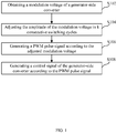
- FIG. 1 schematically shows a method of controlling a wind power converter according to an embodiment of the present disclosure. As shown in FIG. 1 , the method includes the following steps.
- step S101 a modulation voltage of a generator-side converter is obtained.
- step S102 an amplitude of the modulation voltage in k consecutive switching cycles is adjusted.
- a PWM (Pulse Width Modulation) pulse signal is generated according to the adjusted modulation voltage.
- a frequency of the generated PWM pulse signal is 1/k of that of a first PWM pulse signal, wherein k is an integer equal to or greater than 2.
- the frequency of the first PWM pulse signal represents a frequency of a PWM pulse signal generated when the modulation voltage is not adjusted, that is, original.
- step S104 a control signal of the generator-side converter is generated according to the PWM pulse signal.
- the adjusted modulation voltage which is used as a modulation wave
- the frequency of the generated PWM pulse signal is 1/k of the frequency of the original PWM pulse signal. Namely, the switching frequency is reduced to 1/k, thus reducing the switching frequency of the generator-side converter of the wind power converter.
- FIG. 2 schematically shows a wind power generation system 200 according to an embodiment of the present disclosure.
- the wind power generation system 200 includes a wind power generator 201 and a converter.
- a stator winding of the wind power generator is coupled to a power grid 205 through a stator main contactor 203 and a main circuit breaker 204.
- a rotor winding of the wind power generator is coupled to the converter.
- the converter mainly includes a generator-side converter 211, a grid-side converter 212 and a control device 213.
- the generator-side converter 211 is connected to the DC side of the grid-side converter 212 to form a back-to-back connection.
- the grid-side converter 212 is coupled to the stator winding through an inductor-capacitor (LC) filter, an alternating current (AC) fuse protector and a grid-side main contactor. Electric energy generated by the stator winding and the rotor winding is transmitted to the power grid.
- LC inductor-capacitor
- AC alternating current
- the control device 213 includes a rotating-speed calculation module 2131, a slip calculation module 2132, a torque control module 2133, a section determination module 2134, a modulation wave adjustment module 2135, a selection module 2136 and a PWM modulation module 2137.
- the rotating-speed calculation module 2131 is coupled to the wind power generator 201, for calculating a rotating-speed n of the wind power generator.
- the slip calculation module 2132 is coupled to the rotating-speed calculation module, and configured to calculate a slip S according to the rotating-speed n and a synchronous rotating-speed n 0 , and compare the slip S with a threshold.
- the rotating-speed n is close to or equal to the synchronous rotating-speed n 0 when the slip S is equal to or less than the threshold; and the rotating-speed n is greater than the synchronous rotating-speed n 0 when the slip S is greater than the threshold.
- the threshold is equal to 0.01, but the present disclosure is not limited to this, and it can be flexibly set according to actual needs.
- the torque control module 2133 is coupled to the slip calculation module and a sampling module, and configured to obtain a three-phase modulation voltage U abc according to the slip S, a power grid voltage u gabc and a power grid current i gabc .
- the sampling module (not shown) may be located within the control device, or may be an external sampling module.
- the torque control module 2133 may also be referred to as a modulation wave acquisition module, which is configured to output a modulation wave or a modulation wave signal, i.e., a modulation voltage.
- the section determination module 2134 is coupled to the torque control module 2133, and configured to receive the three-phase modulation voltage U abc and determine a section at which the three-phase modulation voltage is located.
- we can section the value range of the modulation voltage (eg. 0 ⁇ 1) to form a number of intervals, and each of the invertals is called Section i, i 1,2...
- the modulation wave adjustment module 2135 is coupled to the torque control module and the section determination module, and configured to receive the three-phase modulation voltage U abc output by the torque control module and adjust it according to the section output by the section determination module 2134 to obtain the adjusted three-phase modulation voltage signal U * abc .
- the selection module 2136 is coupled to the slip calculation module, the torque control module and the modulation wave adjustment module, and configured to receive the determination result SS output by the slip calculation module and select to output the modulation voltage U abc or U * abc according to the determination result SS. As shown in FIG. 2 , the selection module 2136 is composed of a first switch and a second switch.
- the PWM modulation module 2137 receives the modulation voltage output by the selection module, compares the modulation voltage, which is used as a modulation wave signal, with a carrier wave to obtain a PWM pulse signal. A control signal of the generator-side converter is generated according to the PWM pulse signal.
- the PWM modulation module may generate a pulse signal by for example SPWM (Sinusoidal PWM) or SVPWM (Space Vector PWM) technology, but it is not limited thereto.
- the control device 213 further includes a control signal generation module (not shown) which is coupled to the PWM modulation module and configured to generate a control signal for each switching device in a generator-side converter according to the PWM pulse signal. Electric energy conversion can be realized by a switching operation of the switching devices. For example, by inverting the PWM pulse signal and adding dead zone control, two sets of control signals are obtained, which are control signals of an upper bridge arm switch and a lower bridge arm switch of a corresponding bridge arm, respectively.
- a control signal generation module (not shown) which is coupled to the PWM modulation module and configured to generate a control signal for each switching device in a generator-side converter according to the PWM pulse signal. Electric energy conversion can be realized by a switching operation of the switching devices. For example, by inverting the PWM pulse signal and adding dead zone control, two sets of control signals are obtained, which are control signals of an upper bridge arm switch and a lower bridge arm switch of a corresponding bridge arm, respectively.
- the torque control module may use other control loops or controllers, such as a power control loop, a voltage and current control loop as well, as long as the modulation signal can be obtained.
- control logic whether to execute the function of adjusting the modulation wave is selected according to the determination result SS of the slip calculation module. Specifically, if the determination result SS is Y, the function of adjusting the modulation wave is executed, that is, the section determination module and the modulation wave adjustment module are activated, and the adjusted three-phase modulation voltage U * abc is output to the PWM modulation module; and if the determination result SS is N, the function of adjusting the modulation wave is not executed, that is, the section determination module and the modulation wave adjustment module are shielded, and the original three-phase modulation voltage U abc is directly output to the PWM modulation module.
- the generator-side converter When the rotor of the wind power generator runs at a speed approximate to a synchronous rotating-speed, the generator-side converter operates in a DC state, and the three-phase modulation voltage U abc is approximate to a fixed value.
- the amplitude of the modulation voltage U abc every T/2 is adjusted to obtain a three-phase modulation voltage U * abc whose cycle is kT and whose amplitude is segmentally varied, wherein T is the cycle of the modulation wave signal U abc .
- the three-phase modulation voltage U * abc which is used as a three-phase modulation wave signal, is compared with a carrier wave signal to obtain an adjusted PWM pulse signal having a frequency of f/k, and a control signal of the generator-side converter is generated according to the adjusted PWM pulse signal, such that the switching frequency of the generator-side converter is reduced to f/k, where k is an integer greater than 1.
- the modulation wave signal U abc is compared with the carrier wave to generate the first PWM pulse signal, and f is the frequency of the first PWM pulse signal.
- the rotating-speed n may be compared with the synchronous rotating-speed n 0 to determine whether the rotating-speed n is close to the synchronous rotating-speed n 0 , and the determination result is output to the selection module.
- control device may be a processor or a computer chip, but the present disclosure is not limited thereto.
- the modulation voltage U x takes one-phase modulation voltage U x as an example, where x is any of a, b and c.
- An operating rotating-speed of the wind power generator is obtained, and it is determined whether the difference between the operating rotating-speed and the synchronous rotating-speed is less than or equal to a predetermined threshold. If it is less than or equal to the predetermined threshold, the amplitude of the modulation voltage U x in k consecutive switching cycles is adjusted; and if it is greater than the predetermined threshold, the modulation voltage U x is not adjusted.
- the modulation voltage U x is adjusted.
- the determination of section of the modulation voltage U x is performed and the amplitude of the modulation voltage U x in a plurality of consecutive switching cycles is adjusted according to the determination result, and the switching frequency is finally reduced to 1/2 of the original switching frequency.
- FIG. 3 schematically shows the steps of adjusting the modulation voltage U x .
- the modulation voltage U x output by a loop control (e.g. the torque control module 2133) of the generator-side converter is obtained at first, then the section of the modulation voltage U x is determined and the amplitude of the modulation voltage U x in two consecutive switching cycles is adjusted according to the determination result, and finally, the adjusted modulation voltage U* x is outputted, thus reducing the switching frequency to 1/2 of the original switching frequency.
- a loop control e.g. the torque control module 2133
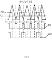
- FIG. 4 schematically shows a waveform diagram of each signal when U x is located at section 1 in this embodiment.
- U x is an approximate fixed value less than or equal to 0.5
- the adjusted modulation voltage U x * is a pulse signal with a cycle of 2T and an amplitude of 2U x or 0.
- the adjusted modulation voltage U x * which is used as a modulation wave, is compared with a triangular wave to obtain a PWM pulse signal, which is marked as a second PWM pulse signal 402 in FIG. 4 .
- the unadjusted modulation voltage U x is compared with the triangular wave to obtain a PWM pulse signal, which is marked as a first PWM pulse signal 401 in FIG. 4 .
- the frequency of the second PWM pulse signal is 1/2 of that of the first PWM pulse signal.
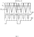
- FIG. 5 schematically shows a waveform diagram of each signal when U x is located at section 2 in this embodiment.
- U x is an approximate fixed value greater than 0.5
- the adjusted modulation voltage U x * is a pulse signal with a cycle of 2T and the amplitude of 2U x -1 or 1.
- the adjusted modulation voltage U x * is compared with a triangular wave to obtain a PWM pulse signal, which is marked as a second PWM pulse signal 502 in FIG. 5 .
- the unadjusted modulation voltage U x is compared with the triangular wave to obtain a PWM pulse signal, which is marked as a first PWM pulse signal 501 in FIG. 5 .
- the frequency of the second PWM pulse signal is 1/2 of that of the first PWM pulse signal.
- the modulation voltage U x at the AC side port of the generator-side converter may fluctuate frequently around 0.5, thus the above-described two methods of adjustment of the modulation wave will be frequently switched, which may cause loss of pulses during switching, thus leading to distortion of current.
- a common mode component is injected into the modulation voltage U x output by the loop control (e.g. torque control), such that most of the modulation voltage U x as a whole rises above 0.5 or reduces below 0.5, avoiding frequent switching of the above-described two methods of adjustment of the modulation wave.
- FIG. 6A schematically shows another wind power generation system according to this embodiment.
- a wind power generation system 600 in this embodiment differs from the wind power generation system 200 in the first embodiment mainly in that a control device 613 further includes a common mode signal injection module 6138, which is coupled between a torque control module 6133 and a section determination module 6134.
- the common mode signal injection module 6138 together with the torque control module 6133 can be referred to as a modulation wave acquisition module.
- the torque control module 6133 outputs an initial modulation wave signal U abc0
- the common mode signal injection module 6138 is configured to receive the initial modulation wave signal and inject a common mode signal U cm therein, that is, superimpose the common mode signal U cm in the initial modulation wave signal U abc0 to obtain a modulation Voltage U abc .
- a section determination module 234 receives the modulation voltage U abc and determines the section where U abc is located.
- a modulation wave adjustment module 6135 is coupled to the common mode injection module and the section determination module, and configured to receive the modulation voltage U abc output by the common mode injection module and adjust the modulation voltage U abc according to the section output by the section determination module 6134 to obtain the adjusted three-phase modulation voltage U * abc .
- FIG. 6B schematically shows the steps of adjusting the modulation voltage U x in the second embodiment. As shown in FIG.
- an initial modulation voltage U x0 output from a loop control of the generator-side converter is obtained at first, and the modulation voltage U x0 is adjusted when the difference between an operating rotating-speed n and a synchronous rotating-speed n 0 is less than or equal to a predetermined threshold (e.g. 0.01). Since the rotating-speed of the rotor of the wind power generator fluctuates around the synchronous rotating-speed, the modulation voltage U x0 at the AC side port of the generator-side converter may frequently fluctuate around 0.5. To solve this problem, a common mode voltage is injected into the initial modulation voltage U x0 , such that most of the modulation voltage U x0 rises above 0.5 or reduces below 0.5.
- U x0 denotes the modulation voltage U x output from the loop control.
- the modulation voltage U x of the generator-side converter is obtained after the injection of the common mode voltage, then the determination of section of the modulation voltage U x is performed, the amplitude of the modulation voltage U x in two consecutive switching cycles is adjusted according to the determination result, and finally the adjusted modulation voltage U * x is output, thus reducing the switching frequency to 1/2 of the original switching frequency.
- a waveform diagram of each signal when U x is located at section 1 and a waveform diagram of each signal when U x is located at section 2 are similar to those in FIGs. 4 and 5 respectively, and will not be elaborated here.
- the modulation voltage U x is adjusted, then the determination of section of the modulation voltage U x is performed, and the amplitude of the modulation voltage U x in three consecutive switching cycles is adjusted according to the determination result, and finally the adjusted modulation voltage U * x is output, thus reducing the switching frequency to 1/3 of the original switching frequency.
- a predetermined threshold e.g. 0.01
- Table 3 the amplitude of the modulation voltage U x in 3 consecutive switching cycles
- U x * 3U x -1
- U x * 1
- FIG. 7 schematically shows a waveform diagram of each signal when U x is located at section 1 in this embodiment.
- U x is an approximate fixed value greater than 0 and equal to or less than 1/3
- the adjusted modulation voltage U x * is a pulse signal with a cycle of 3T and an amplitude of 3U x or 0.
- the adjusted modulation voltage U x * is compared with a triangular wave to obtain a PWM pulse signal, which is marked as a second PWM pulse signal 602 in FIG. 7 .
- the unadjusted modulation voltage U x is compared with the triangular wave to obtain a PWM pulse signal, which is marked as a first PWM pulse signal 601 in FIG. 7 .
- the frequency of the second PWM pulse signal is 1/3 of that of the first PWM pulse signal.
- FIG. 8 schematically shows a waveform diagram of each signal when U x is located at section 2 in this embodiment.
- U x is an approximate fixed value greater than 1/3 or equal to or less than 2/3
- the adjusted modulation voltage U x * is a signal with a cycle of 3T and an amplitude segmentally varied, which are 3U x -1, 0 or 1.
- the adjusted modulation voltage U x * is compared with a triangular wave to obtain a PWM pulse signal, which is marked as a second PWM pulse signal 702 in FIG. 8 .
- the unadjusted modulation voltage U x is compared with the triangular wave to obtain a PWM pulse signal, which is marked as a first PWM pulse signal 701 in FIG. 8 .
- the frequency of the second PWM pulse signal is 1/3 of that of the first PWM pulse signal.
- FIG. 9 schematically shows a waveform diagram of each signal when U x is located at section 3 in this embodiment. As shown in FIG. 9 , U x is an approximate fixed value greater than 2/3 or less than 1, and the adjusted modulation voltage U x * is a pulse signal with a cycle of 3T and an amplitude of 3U x -2 or 1.
- the adjusted modulation voltage U x * is compared with a triangular wave to obtain a PWM pulse signal, which is marked as a second PWM pulse signal 802 in FIG. 8 .
- the unadjusted modulation voltage U x is compared with the triangular wave to obtain a PWM pulse signal, which is marked as a first PWM pulse signal 801 in FIG. 8 .
- the frequency of the second PWM pulse signal is 1/3 of that of the first PWM pulse signal.
- the modulation voltage U x at the AC side port of the generator-side converter fluctuates frequently around 1/3 or 2/3.
- a common mode component can be injected into the above-mentioned solution, such that most of the modulation voltage U x rises or drops as a whole.
- the determination of section of the modulation voltage U x is performed, and the amplitude of the modulation voltage U x in a plurality of consecutive switching cycles is adjusted according to the determination result, and finally the switching frequency is reduced to 1/k of the original switching frequency.
- the predetermined threshold e.g. 0.01
- adjusting the amplitude of the modulation voltage U x in k consecutive switching cycles includes:
- a main circuit of the generator-side converter is a two-level circuit and the value range of the normalized modulation voltage is: 0 ⁇ U x ⁇ 1.
- x-phase PWM pulse signal such as 402, 502, 602
- x is any of a, b and c
- two sets of control signals are obtained by inverting the PWM pulse signal and adding the dead zone control, which are control signals of upper and lower bridge arm switches of a bridge arm corresponding to the x-phase, respectively.
- the main circuit of the generator-side converter can be a multi-level circuit as well, for example a three-level circuit topology. Compared with a two-level bridge circuit, the multi-level circuit has the advantages of low switch voltage stress and good output voltage quality.
- a modulation voltage of the three-level circuit is approximate to a DC quantity, thus the adjustment method of the modulation voltage of the present disclosure can be used to reduce the switching frequency.
- the value range of the modulation voltage of the three-level circuit is: -1 ⁇ U x ⁇ 1. The method for adjusting the modulation voltage of the three-level circuit will described below according to specific embodiments.
- PWM modules integrated in a Digital Signal Processor (DSP) or a Microcontroller Module (MCU) are usually used to generate pulse signals, and technicians only need to configure the corresponding register while programming.
- DSP Digital Signal Processor
- MCU Microcontroller Module
- This embodiment adopts PWM modulation based on the carrier wave phase disposition.
- U x When -1/2 ⁇ U x ⁇ 0, U x is located at section 3 and the amplitude of the modulation voltage U x is adjusted to 2U x or 0 to obtain the adjusted modulation voltage U * x ; and when -1 ⁇ U x ⁇ -1/2, U x is located at section 4 and the amplitude of the modulation voltage U x is adjusted to 2U x -1 or 1 to obtain the adjusted modulation voltage U* x .
- Table 5 the amplitude of the modulation voltage U x in 2 consecutive switching cycles.
- FIG. 10 schematically shows a waveform diagram of each signal when U x is located at section 1 in this embodiment.
- U x is an approximate fixed value greater than 0 and equal to or less than 0.5
- the adjusted modulation voltage U x * is a pulse signal with a cycle of 2T and an amplitude of 2U x or 0.
- the adjusted modulation voltage U x * which is used as a modulation wave, is compared with a triangular carrier wave to obtain a PWM pulse signal, which is marked as a second PWM pulse signal 902 in FIG. 10 .
- the unadjusted modulation voltage U x is compared with the triangular wave to obtain a PWM pulse signal, which is marked as a first PWM pulse signal 901 in FIG. 10 .
- the frequency of the second PWM pulse signal is 1/2 of that of the first PWM pulse signal.
- FIG. 11 schematically shows a waveform diagram of each signal when U x is located at section 2 in this embodiment.
- U x is an approximate fixed value greater than 0.5 and less than 1
- the adjusted modulation voltage U x * is a pulse signal with a cycle of 2T and an amplitude of 2U x -1 or 1.
- the adjusted modulation voltage U x * is compared with a triangular wave to obtain a PWM pulse signal, which is marked as a second PWM pulse signal 1002 in FIG. 11 .
- the unadjusted modulation voltage U x is compared with the triangular wave to obtain a PWM pulse signal, which is marked as a first PWM pulse signal 1001 in FIG. 11 .
- the frequency of the second PWM pulse signal is 1/2 of that of the first PWM pulse signal.
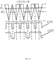
- FIG. 12 schematically shows a waveform diagram of each signal when U x is located at section 3 in this embodiment.
- U x is an approximate fixed value equal to or greater than -0.5 and less than 0, and the adjusted modulation voltage U x * is a pulse signal with a cycle of 2T and an amplitude of 2U x or 0.
- the adjusted modulation voltage U x * is compared with a triangular wave to obtain a PWM pulse signal, which is marked as a second PWM pulse signal 1102 in FIG. 12 .
- the unadjusted modulation voltage U x is compared with the triangular wave to obtain a PWM pulse signal, which is marked as a first PWM pulse signal 1101 in FIG. 12 .
- the frequency of the second PWM pulse signal is 1/2 of that of the first PWM pulse signal.
- FIG. 13 schematically shows a waveform diagram of each signal when U x is located at section 4 in this embodiment.
- U x is an approximate fixed value greater than -1 and less than 0.5
- the adjusted modulation voltage U x * is a pulse signal with a cycle of 2T and an amplitude of 2U x +1 or 1.
- the adjusted modulation voltage U x * is compared with a triangular wave to obtain a PWM pulse signal, which is marked as a second PWM pulse signal 1202 in FIG. 13 .
- the unadjusted modulation voltage U x is compared with the triangular wave to obtain a PWM pulse signal, which is marked as a first PWM pulse signal 1201 in FIG. 13 .
- the frequency of the second PWM pulse signal is 1/2 of that of the first PWM pulse signal.
- the embodiment of the present disclosure adopts PWM modulation based on the carrier wave phase opposition disposition.
- U x When -1/2 ⁇ U x ⁇ 0, U x is located at section 3 and the amplitude of the modulation voltage U x is adjusted to 2U x or 0 to obtain the adjusted modulation voltage U * x ; and when -1 ⁇ U x ⁇ -1/2, U x is located at section 4 and the amplitude of the modulation voltage U x is adjusted to -2U x -1 or -1 to obtain the adjusted modulation voltage U* x .
- Table 6 the amplitude of the modulation voltage U x in 2 consecutive switching cycles.
- FIG. 14 schematically shows a waveform diagram of each signal when U x is located at section 1 in this embodiment.
- U x is an approximate fixed value greater than 0 and equal to or less than 0.5
- the adjusted modulation voltage U x * is a pulse signal with a cycle of 2T and an amplitude of 2U x or 0.
- the adjusted modulation voltage U x * which is used as a modulation wave, is compared with a triangular wave to obtain a PWM pulse signal, which is marked as a second PWM pulse signal 1302 in FIG. 14 .
- the unadjusted modulation voltage U x is compared with the triangular wave to obtain a PWM pulse signal, which is marked as a first PWM pulse signal 1301 in FIG. 14 .
- the frequency of the second PWM pulse signal is 1/2 of that of the first PWM pulse signal.
- FIG. 15 schematically shows a waveform diagram of each signal when U x is located at section 2 in this embodiment.
- U x is an approximate fixed value greater than 0.5 and less than 1
- the adjusted modulation voltage U x * is a pulse signal with a cycle of 2T and an amplitude of 2U x -1 or 1.
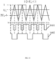
- the adjusted modulation voltage U x * is compared with a triangular wave to obtain a PWM pulse signal, which is marked as a second PWM pulse signal 1402 in FIG. 15 .
- the unadjusted modulation voltage U x is compared with the triangular wave to obtain a PWM pulse signal, which is marked as a first PWM pulse signal 1401 in FIG. 15 .
- the frequency of the second PWM pulse signal is 1/2 of that of the first PWM pulse signal.
- FIG. 16 schematically shows a waveform diagram of each signal when U x is located at section 4 in this embodiment.
- U x is a fixed value equal to or greater than -0.5 and less than 0, and the adjusted modulation voltage U x * is a pulse signal with a cycle of 2T and an amplitude of 2U x or 0.
- the adjusted modulation voltage U x * is compared with a triangular wave to obtain a PWM pulse signal, which is marked as a second PWM pulse signal 1502 in FIG. 16 .
- the unadjusted modulation voltage U x is compared with the triangular wave to obtain a PWM pulse signal, which is marked as a first PWM pulse signal 1501 in FIG. 16 .
- the frequency of the second PWM pulse signal is 1/2 of that of the first PWM pulse signal.
- FIG. 17 schematically shows a waveform diagram of each signal when U x is located at section 3 in this embodiment.
- U x is an approximate fixed value greater than -1 and less than -0.5
- the adjusted modulation voltage U x * is a pulse signal with a cycle of 2T and an amplitude of -2U x -1 or -1.
- the adjusted modulation voltage U x * is compared with a triangular wave to obtain a PWM pulse signal, which is marked as a second PWM pulse signal 1502 in FIG. 17 .
- the unadjusted modulation voltage U x is compared with the triangular wave to obtain a PWM pulse signal, which is marked as a first PWM pulse signal 1501 in FIG. 17 .
- the frequency of the second PWM pulse signal is 1/2 of that of the first PWM pulse signal.
- the modulation voltage at the AC side port of a three-level generator-side converter may fluctuate frequently around +0.5 or -0.5, thus leading to frequently switching of the methods of adjustment of the modulation wave.
- a common mode component can be superimposed on the modulation voltage in the fifth and sixth embodiments, such that most of the modulation voltage as a whole rises above +0.5 or reduces below -0.5. Please refer to the second embodiment for details, which will not be elaborated here.
- the method of controlling the switching frequency of the wind power converter it can adjust the amplitude of the modulation voltage in k consecutive switching cycles, generate a PWM pulse signal according to the adjusted modulation voltage, and reduce the switching frequency of the wind power converter by periodic changes in duty cycles.
- the technical solution of the embodiments of the present disclosure realizes the purpose of reducing the switching frequency without changing clock configuration of a control chip, peripheral initialization configuration of a PWM module, discretization parameters of a control loop, and discretization parameters of a filter, such that it is easy to be implemented, and needs no switching of parameters and has relatively high system reliability.
- an embodiment of the present disclosure further provides a control device of a wind power converter, including a modulation voltage obtaining module 1701, a modulation wave adjustment module 1702, a pulse signal generating module 1703 and a control signal generating module 1704.
- the modulation voltage obtaining module 1701 is configured to obtain a modulation voltage of a generator-side converter.
- the modulation wave adjustment module 1702 is configured to adjust an amplitude of the modulation voltage in k consecutive switching cycles.
- the pulse signal generating module 1703 is configured to generate a PWM pulse signal according to the adjusted modulation voltage, wherein the frequency of the generated PWM pulse signal is 1/k of that of a first PWM pulse signal.
- the frequency of the first PWM pulse signal represents a frequency of a PWM pulse signal generated when the modulation voltage is not adjusted, and k is an integer equal to or greater than 2.
- the control signal generating module 1704 is configured to generate a control signal of the generator-side converter according to the PWM pulse signal.
- the frequency of the generated PWM pulse signal is 1/k of the original frequency, namely, the switching frequency is reduced to 1/k of the original switching frequency, thus reducing the switching frequency of the wind power converter.
- the control device of the wind power converter provided by the embodiment of the present disclosure further includes a rotating-speed obtaining module and a slip calculation module.
- the rotating-speed obtaining module is configured to obtain an operating rotating-speed of a wind power generator.
- the slip calculation module is configured to determine whether the difference between the operating rotating-speed and a synchronous rotating-speed is less than or equal to a predetermined threshold. It may send a start/output command to the modulation wave adjustment module if the difference is less than or equal to the predetermined threshold, and not send on the start/output command to the modulation wave adjustment module if the difference is greater than the predetermined threshold.
- the start/output command corresponds to a start command or an output command.
- the start command refers to enabling the modulation wave adjustment module to adjust the modulation wave and output the adjusted modulation wave.
- the output command refers to outputting the modulation voltage adjusted by the modulation wave adjustment module, at this time, other functions of the modulation wave adjustment module need not to be awakened by a command.
- the modulation wave adjustment module 1702 is configured to adjust the amplitude of the modulation voltage in k consecutive switching cycles after receiving the start/output command.
- the modulation voltage obtaining module 1701 includes a voltage obtaining sub-module and a common-mode voltage injection sub-module.
- the voltage obtaining sub-module is configured to obtain a modulation voltage output by a loop control of the generator-side converter.
- the common-mode voltage injection sub-module is configured to inject a common-mode voltage into the modulation voltage output by the loop control to obtain the modulation voltage of the generator-side converter.
- the modulation wave adjustment module 1702 includes a section determination sub-module and an adjustment sub-module.
- the section determination sub-module is configured to receive the modulation voltage output by the modulation voltage obtaining module 1701 to determine the section where the modulation voltage is located.
- the adjustment sub-module is configured to adjust the modulation voltage according to the section where the modulation voltage is located.
- the control device of the wind power converter of the embodiment of the present disclosure adjusts the amplitude of the modulation voltage in k consecutive switching cycles, generates a PWM pulse signal according to the adjusted modulation voltage, and reduces the switching frequency of the wind power converter by periodic changes in duty cycles.
- An embodiment of the present disclosure further provides a wind power generation system, including a wind power generator, a wind power converter and a control device of the wind power converter in the above-described technical solution.
- the wind power generation system of the embodiments of the present disclosure include the control device in the above-mentioned technical solution, therefore it has the same technical effect as that of the control device, realizes the periodic changes in duty cycles, and reduces the switching frequency of the wind power converter.
- the method and device of reducing the switching frequency of the present application are applicable to other power systems or power equipment, such as full-power wind power generation systems, as well. Therefore, the method of reducing the switching frequency proposed in the present application can be adopted as long as a voltage entering a three-phase port of a power system is approximate to a DC quantity.
- FIG. 19 shows a structural schematic diagram of a computer system 1800 suitable for implementing an electronic device of an embodiment of the present disclosure.
- the computer system 1800 of the electronic device shown in FIG. 19 is only an example, and should not impose any limitations on the function and scope of use of the embodiments of the present disclosure.
- the computer system 1800 includes a central processing unit (CPU) 1801, which can perform various appropriate actions and processing based on programs stored in a read only memory (ROM) 1802 or programs loaded to a random access memory (RAM) 1803 from a storage part 1808.
- ROM read only memory
- RAM random access memory
- Various programs and data required for system operation are also stored in RAM 1803.
- CPU 1801, ROM 1802, and RAM 1803 are connected to one another through a bus 1804.
- An input/output (I/O) interface 1805 is connected to the bus 1804 as well.
- the I/O interface 1805 is connected to the following components: an input part 1806 such as a keyboard, a mouse, or the like; an output part 1807 such as a cathode ray tube (CRT), a liquid crystal display (LCD), a speaker, or the like; a storage part 1808 such as a hard disk, or the like; and a communication part 1809 including a network interface card such as a LAN card, a modem, or the like.
- the communication part 1809 performs communication processing via a network such as the Internet.
- a drive 1810 is connected to the I/O interface 1805 according to the need as well.
- a removable medium 1818 such as a magnetic disk, an optical disk, a magneto-optical disk, a semiconductor memory, or the like, is installed on the drive 1810 as needed, such that computer program read therefrom can be installed into the storage part 1808 as needed.
- an embodiment of the present disclosure includes a computer program product, which includes computer programs which are carried on a computer-readable medium, and contain program codes for performing the method shown in the flowcharts.
- the computer program may be downloaded and installed from the network through the communication part 1809, and/or installed from the removable medium 1811.
- the central processing unit (CPU) 1801 When executed by the central processing unit (CPU) 1801, the computer program performs the above-mentioned functions defined in the system of the present application.
- the computer-readable medium shown in the present disclosure may be a computer-readable signal medium or a computer-readable storage medium, or any combination thereof.
- the computer-readable storage medium may be, for example, but not limited to, electrical, magnetic, optical, electromagnetic, infrared or semiconductor systems, apparatuses or devices, or any combination thereof. More specific examples of the computer-readable storage medium may include, but are not limited to, electrical connections with one or more wires, a portable computer disk, a hard disk, a random access memory (RAM), a read-only memory (ROM), an erasable programmable read-only memory (EPROM or flash memory), an optical fiber, a portable compact disk read-only memory (CD-ROM), an optical storage, a magnetic storage, or any suitable combination thereof.
- the computer-readable storage medium may be any tangible medium that contains or stores programs, which may be used by or in combination with a command execution system, apparatus, or device.
- a computer-readable signal medium may include a data signal transmitted in a baseband or as part of a carrier wave, which carries computer-readable program codes.
- the transmitted data signal may be represented in many forms, including, but not limited to, an electromagnetic signal, an optical signal, or any suitable combination thereof.
- the computer-readable signal medium may also be any computer-readable medium other than a computer-readable storage medium, which may send, propagate or transmit programs which are used by, or in conjunction with a command execution system, apparatus or device.
- Program codes contained on the computer-readable medium may be transmitted with any appropriate medium, which includes, but is not limited to, wireless, wired, an optical cable, RF, etc., or any suitable combination thereof.
- each block in the flowcharts or block diagrams can represent a module, a program segment, or a portion of codes, which contains one or more executable instructions for realizing specified logic functions.
- the functions indicated in the blocks may also be performed in other orders than that indicated in the drawings. For example, two blocks shown in succession may actually be executed almost simultaneously, or sometimes, in a reverse order, which depends on the functions.
- each of blocks, or a combination of blocks in the block diagram or flowchart can be implemented by a dedicated hardware-based system that performs specified functions or operations, or by a combination of dedicated hardware and computer instructions.
- the modules described in the embodiments of the present disclosure may be implemented by software, or hardware, and the described modules may also be provided in a processor. Names of the modules do not impose any limitations on the modules themselves under certain circumstances.
- the present disclosure further provides a computer-readable medium, which may be included in the electronic device described in the above-mentioned embodiment, or may exist alone without being mounted in the electronic device.
- the above-mentioned computer-readable medium carries one or more programs which, when executed by an electronic device, allow the electronic device to perform the interactive question and answer method described in the above-mentioned embodiment.
- the electronic device can carry out the steps as shown in FIG. 1 .
- step S101 a modulation voltage of a generator-side converter is obtained.
- step S102 the amplitude of the modulation voltage in k consecutive switching cycles is adjusted.
- step S103 a PWM pulse signal is generated according to the adjusted modulation voltage, wherein the frequency of the generated PWM pulse signal is 1/k of the frequency of a first PWM pulse signal, k is an integer equal to or greater than 2, and the frequency of the first PWM pulse signal represents the frequency of a PWM pulse signal generated when the modulation voltage is not adjusted.
- step S104 a control signal of the generator-side converter is generated according to the PWM pulse signal.
- modules or modules of a device for carrying out actions are mentioned in the detailed descriptions above, such division is not mandatory.
- features and functions of two or more of the modules or modules described above may be embodied in one module or module in accordance with the embodiments of the present disclosure.
- the features and functions of one module or module described above may be further embodied by a plurality of modules or modules.
- the exemplary embodiments described herein can be implemented by software, or by software in combination with necessary hardware. Therefore, the technical solution according to the embodiment of the present disclosure can be embodied in the form of a software product, which can be stored in a non-volatile storage medium (CD-ROM, U disk, mobile hard disk, etc.) or on the network, and includes several instructions to allow a computing device (a personal computer, a server, a touch terminal, or a network device, etc.) to execute the method according to the embodiment of the present disclosure.
- a computing device a personal computer, a server, a touch terminal, or a network device, etc.
Landscapes
- Engineering & Computer Science (AREA)
- Power Engineering (AREA)
- Control Of Eletrric Generators (AREA)
Abstract
Description
- The present disclosure relates to power electronics technology, more particularly, to a method of controlling a switching frequency of a wind power converter, a control device using the method, a wind power generation system using the method, a medium thereof and an electronic device using the same.
- In order to increase generating capacity at a low wind speed, it is required that a wind power converter can operate for a long-term when a rotor of a wind power generator runs at a speed approximate to a synchronous rotating-speed. When the rotor of the wind power generator is at a rotating-speed approximate to a synchronous rotating-speed, current of the rotor is approximate to direct current (DC), and the loss is large, but reducing the switching frequency of a double-fed wind power converter can reduce the loss.
- In the related technology, the switching frequency of the double-fed wind power converter may be reduced by modifying peripheral configuration of a control chip. For example, switching frequencies, control parameters or filtering parameters may be switched online. In order to use such methods, the installed wind power generators have to be changed greatly, the processes of switching the controlling parameters are complicated, and the reliability is low, which is not conducive to later development.
- Reducing switching frequencies of wind power converters by combining with the operating characteristics of the wind power converters without changing the present control parameters and system configuration, is a technical problem that urgently needs to be solved.
- It should be noted that information disclosed in this part are provided only for acquiring a better understanding of the background of the present application and therefore may include information that is not present technology already known to those of ordinary skill in the art.
- An objective of the present disclosure is to provide a method of controlling a switching frequency of a wind power converter, a control device using the method, a wind power generation system using the method, a medium thereof and an electronic device using the same, thereby overcoming, at least to some extent, one or more problems caused by the limitations and defects of related technologies.
- According to a first aspect of the present disclosure, there is provided a method of controlling a switching frequency of a wind power converter, including: obtaining a modulation voltage of a generator-side converter; adjusting amplitude of the modulation voltage in k consecutive switching cycles; generating a PWM pulse signal according to the adjusted modulation voltage, wherein a frequency of the generated PWM pulse signal is 1/k of a frequency of a first PWM pulse signal, k is an integer equal to or greater than 2, and the frequency of the first PWM pulse signal represents a frequency of a PWM pulse signal generated when the modulation voltage is not adjusted; and generating a control signal of the generator-side converter according to the PWM pulse signal.
- In some embodiments, the method further includes: obtaining an operating rotating-speed of a wind power generator; determining whether a difference between the operating rotating-speed and a synchronous rotating-speed is less than or equal to a predetermined threshold, and adjusting the amplitude of the modulation voltage in the k consecutive switching cycles if the difference is less than the predetermined threshold, and not adjusting the modulation voltage if the difference greater than the predetermined threshold.
- In some embodiments, adjusting the amplitude of the modulation voltage in the k consecutive switching cycles includes: when 0<Ux≤ 1/k, Ux*=kUx, N=1, 2; and Ux*=0, N=3,..., 2k;
when (m-1)/k<Ux≤m/k, Ux*=kUx-m+1, N=1; Ux*=1, N=2,..., 2m-1;
Ux*=kUx-m+1, N=2m; and Ux*=0, N=2m+1,..., 2k; and
when (k-1)/k<Ux<1, Ux*=kUx-k+1, N=1; Ux*=1, N=2,..., 2k-1,
wherein Ux is the modulation voltage, Ux* is the adjusted modulation voltage, m is an integer greater than 1 and less than k, and N is a natural number, a value of which is taken from 2k consecutive half-switching cycles of the switching cycle. - In some embodiments, k=2,


- In some embodiments, k=3,


- In some embodiments, obtaining the modulation voltage of the generator-side converter includes: obtaining a modulation voltage output by a loop control of the generator-side converter; and injecting a common mode voltage into the modulation voltage output by the loop control to obtain the modulation voltage of the generator-side converter.
- In some embodiments, the common mode voltage Ucm is denoted as:

- In some embodiments, adjusting the amplitude of the modulation voltage in the k consecutive switching cycles includes: k=2,




- In some embodiments, adjusting the amplitude of the modulation voltage in the k consecutive switching cycles includes: k=2,


- According to a second aspect of the present disclosure, there is provided a control device of a wind power converter, including: a modulation voltage obtaining module, configured to obtain a modulation voltage of a generator-side converter; a modulation wave adjustment module, configured to adjust amplitude of the modulation voltage in k consecutive switching cycles; a pulse signal generating module, configured to generate a PWM pulse signal according to the adjusted modulation voltage, wherein a frequency of the generated PWM pulse signal is 1/k of a frequency of a first PWM pulse signal, and the frequency of the first PWM pulse signal represents a frequency of a PWM pulse signal generated when the modulation voltage is not adjusted, k is an integer equal to or greater than 2; and a control signal generating module, configured to generate a control signal of the generator-side converter according to the PWM pulse signal.
- In some embodiments, the control device further includes: a rotating-speed obtaining module, configured to obtain an operating rotating-speed of a wind power generator; and a slip calculation module, configured to determine whether a difference between the operating rotating-speed and a synchronous rotating-speed is less than or equal to a predetermined threshold, and send a start/output command to the modulation wave adjustment module if the difference is less than the predetermined threshold, and send no start/output command to the modulation wave adjustment module if the difference is greater than the predetermined threshold, wherein the modulation wave adjustment module is configured to adjust the amplitude of the modulation voltage in the k consecutive switching cycles after receiving the start/output command.
- In some embodiments, the modulation voltage obtaining module includes: a voltage obtaining sub-module, configured to obtain a modulation voltage output by a loop control of the generator-side converter; and a common-mode voltage injection sub-module, configured to inject a common mode voltage into the modulation voltage output by the loop control to obtain the modulation voltage of the generator-side converter.
- In some embodiments, the modulation wave adjustment module includes: a section determination sub-module, configured to receive the modulation voltage of the generator-side converter to determine a section where the modulation voltage is located; and an adjustment sub-module configured to adjust the amplitude of the modulation voltage in the k consecutive switching cycles according to the section where the modulation voltage is located.
- According to a third aspect of the present disclosure, there is provided a wind power generation system, including: a wind power generator, a wind power converter, and the control device of the wind power converter according to the second aspect of the present disclosure.
- The technical solutions provided by the embodiments of the present disclosure have at least the following beneficial effects.
- The technical solution of the present disclosure adjusts the amplitude of the modulation voltage in the k consecutive switching cycles, generates a PWM pulse signal according to the adjusted modulation voltage, and reduces the switching frequency of the wind power converter by periodic changes in duty cycles.
- It is to be understood that both the foregoing general description and the following detailed description are exemplary and explanatory only and are not restrictive of the present disclosure, as claimed.
- The accompanying drawings, which are incorporated in and constitute part of this specification, illustrate embodiments consistent with the present disclosure and, together with the description, serve to explain the principles of the present disclosure. Apparently, the drawings in the following description are only for illustrating some embodiments of the present disclosure and those of ordinary skill in the art can also derive other drawings based on the drawings without paying any creative labor.
-
FIG. 1 is a flowchart schematically showing a method of controlling a switching frequency of a wind power converter according to an embodiment of the present disclosure; -
FIG. 2 is a diagram schematically showing a wind power generation system according to an embodiment of the present disclosure; -
FIG. 3 is a flowchart schematically showing the adjustment of the modulation voltage according to an embodiment of the present disclosure; -
FIG. 4 is a waveform diagram schematically illustrating each signal when Ux is located atsection 1 according to an embodiment of the present disclosure; -
FIG. 5 is a waveform diagram schematically illustrating each signal when Ux is located atsection 2 according to an embodiment of the present disclosure; -
FIG. 6A is a diagram schematically illustrating a wind power generation system according to another embodiment of the present disclosure; -
FIG. 6B is a flowchart schematically illustrating the adjustment of the modulation voltage according to another embodiment of the present disclosure; -
FIG. 7 is a waveform diagram schematically illustrating each signal when Ux is located atsection 1 according to further another embodiment of the present disclosure; -
FIG. 8 is a waveform diagram schematically illustrating each signal when Ux is located atsection 2 according to further another embodiment of the present disclosure; -
FIG. 9 is a waveform diagram schematically illustrating each signal when Ux is located atsection 3 according to further another embodiment of the present disclosure; -
FIG. 10 is a waveform diagram schematically illustrating each signal when Ux is located atsection 1 according to still another embodiment of the present disclosure; -
FIG. 11 is a waveform diagram schematically illustrating each signal when Ux is located atsection 2 according to still another embodiment of the present disclosure; -
FIG. 12 is a waveform diagram schematically illustrating each signal when Ux is located atsection 3 according to still another embodiment of the present disclosure; -
FIG. 13 is a waveform diagram schematically illustrating each signal when Ux is located atsection 4 according to still another embodiment of the present disclosure; -
FIG. 14 is a waveform diagram schematically illustrating each signal when Ux is located atsection 1 according to still another embodiment of the present disclosure; -
FIG. 15 is a waveform diagram schematically illustrating each signal when Ux is located atsection 2 according to still another embodiment of the present disclosure; -
FIG. 16 is a waveform diagram schematically illustrating each signal when Ux is located atsection 3 according to still another embodiment of the present disclosure; -
FIG. 17 is a waveform diagram schematically illustrating each signal when Ux is located atsection 4 according to still another embodiment of the present disclosure; -
FIG. 18 is a block diagram schematically illustrating a control device of a wind power converter according to an embodiment of the present disclosure; and -
FIG. 19 is a structural diagram schematically showing a computer system suitable for implementing an electronic device according to an embodiment of the present disclosure. - Exemplary embodiments will now be described more fully by reference to the accompanying drawings. However, the exemplary embodiments can be implemented in various forms and should not be understood as being limited to the examples set forth herein; rather, the embodiments are provided so that this disclosure will be thorough and complete, and the conception of exemplary embodiments will be fully conveyed to those skilled in the art.
- Furthermore, the described features, structures or characteristics may be combined in one or more embodiments in any appropriate way. In the following description, many specific details are provided for fully understanding embodiments of the present disclosure. However, it will be appreciated by those skilled in the art that technical solutions of the present disclosure can be practiced without one or more of the specific details, or, other methods, components, devices and steps may be used. Under other circumstances, well-known methods, devices, implementations or operations will not be illustrated or described in detail, to avoid obscuration of various aspects of the present disclosure.
- The block diagrams shown in the drawings are merely functional entities, and are not necessarily corresponding to physically separate entities. That is, the functional entities can be implemented in the form of software, or in one or more hardware modules or integrated circuits, or in different networks and/or processor devices and/or microcontroller devices.
- The flowcharts shown in the drawings are only illustrations, and are neither necessarily including all contents or operations/steps, nor performed in the described order. For example, some of the operations/steps may be divided, and some of them may be combined or partially combined, so the actual order may be changed according to actual conditions.
-
FIG. 1 schematically shows a method of controlling a wind power converter according to an embodiment of the present disclosure. As shown inFIG. 1 , the method includes the following steps. - In step S101, a modulation voltage of a generator-side converter is obtained.
- In step S102, an amplitude of the modulation voltage in k consecutive switching cycles is adjusted.
- In step S103, a PWM (Pulse Width Modulation) pulse signal is generated according to the adjusted modulation voltage. A frequency of the generated PWM pulse signal is 1/k of that of a first PWM pulse signal, wherein k is an integer equal to or greater than 2. The frequency of the first PWM pulse signal represents a frequency of a PWM pulse signal generated when the modulation voltage is not adjusted, that is, original.
- In step S104, a control signal of the generator-side converter is generated according to the PWM pulse signal.
- In the technical solution of the embodiment of the present disclosure, by adjustment of the amplitude of the modulation voltage in k consecutive switching cycles, the adjusted modulation voltage, which is used as a modulation wave, is compared with a carrier wave, and the frequency of the generated PWM pulse signal is 1/k of the frequency of the original PWM pulse signal. Namely, the switching frequency is reduced to 1/k, thus reducing the switching frequency of the generator-side converter of the wind power converter.
-
FIG. 2 schematically shows a windpower generation system 200 according to an embodiment of the present disclosure. Referring toFIGs. 1 and2 , the windpower generation system 200 includes awind power generator 201 and a converter. A stator winding of the wind power generator is coupled to apower grid 205 through a statormain contactor 203 and amain circuit breaker 204. A rotor winding of the wind power generator is coupled to the converter. The converter mainly includes a generator-side converter 211, a grid-side converter 212 and acontrol device 213. The generator-side converter 211 is connected to the DC side of the grid-side converter 212 to form a back-to-back connection. The grid-side converter 212 is coupled to the stator winding through an inductor-capacitor (LC) filter, an alternating current (AC) fuse protector and a grid-side main contactor. Electric energy generated by the stator winding and the rotor winding is transmitted to the power grid. The operation mechanism of the wind power generation system is not the focus of the present disclosure, and thus will not be elaborated here. - In the embodiment, the
control device 213 includes a rotating-speed calculation module 2131, aslip calculation module 2132, atorque control module 2133, asection determination module 2134, a modulationwave adjustment module 2135, aselection module 2136 and aPWM modulation module 2137. The rotating-speed calculation module 2131 is coupled to thewind power generator 201, for calculating a rotating-speed n of the wind power generator. Theslip calculation module 2132 is coupled to the rotating-speed calculation module, and configured to calculate a slip S according to the rotating-speed n and a synchronous rotating-speed n0, and compare the slip S with a threshold. The rotating-speed n is close to or equal to the synchronous rotating-speed n0 when the slip S is equal to or less than the threshold; and the rotating-speed n is greater than the synchronous rotating-speed n0 when the slip S is greater than the threshold. In this embodiment, the threshold is equal to 0.01, but the present disclosure is not limited to this, and it can be flexibly set according to actual needs. Thetorque control module 2133 is coupled to the slip calculation module and a sampling module, and configured to obtain a three-phase modulation voltage Uabc according to the slip S, a power grid voltage ugabc and a power grid current igabc. The sampling module (not shown) may be located within the control device, or may be an external sampling module. In this embodiment, thetorque control module 2133 may also be referred to as a modulation wave acquisition module, which is configured to output a modulation wave or a modulation wave signal, i.e., a modulation voltage. Thesection determination module 2134 is coupled to thetorque control module 2133, and configured to receive the three-phase modulation voltage Uabc and determine a section at which the three-phase modulation voltage is located. In this invention, we can section the value range of the modulation voltage (eg. 0∼1) to form a number of intervals, and each of the invertals is called Section i, i=1,2... - The modulation
wave adjustment module 2135 is coupled to the torque control module and the section determination module, and configured to receive the three-phase modulation voltage Uabc output by the torque control module and adjust it according to the section output by thesection determination module 2134 to obtain the adjusted three-phase modulation voltage signal U* abc. Theselection module 2136 is coupled to the slip calculation module, the torque control module and the modulation wave adjustment module, and configured to receive the determination result SS output by the slip calculation module and select to output the modulation voltage Uabc or U* abc according to the determination result SS. As shown inFIG. 2 , theselection module 2136 is composed of a first switch and a second switch. When the determination result SS of the slip calculation module is Y (Yes), the first switch is turned on and the second switch is turned off, thereby outputting the three-phase modulation voltage U* abc; and when the determination result SS of the slip calculation module is N (No), the first switch is turned off and the second switch is turned on, thereby outputting the three-phase modulation voltage Uabc. This is only an implementation manner of the selection module, and the present disclosure is not limited thereto. ThePWM modulation module 2137 receives the modulation voltage output by the selection module, compares the modulation voltage, which is used as a modulation wave signal, with a carrier wave to obtain a PWM pulse signal. A control signal of the generator-side converter is generated according to the PWM pulse signal. The PWM modulation module may generate a pulse signal by for example SPWM (Sinusoidal PWM) or SVPWM (Space Vector PWM) technology, but it is not limited thereto. - The
control device 213 further includes a control signal generation module (not shown) which is coupled to the PWM modulation module and configured to generate a control signal for each switching device in a generator-side converter according to the PWM pulse signal. Electric energy conversion can be realized by a switching operation of the switching devices. For example, by inverting the PWM pulse signal and adding dead zone control, two sets of control signals are obtained, which are control signals of an upper bridge arm switch and a lower bridge arm switch of a corresponding bridge arm, respectively. - The torque control module may use other control loops or controllers, such as a power control loop, a voltage and current control loop as well, as long as the modulation signal can be obtained.
- It should be noted that there is also another control logic in the present disclosure: whether to execute the function of adjusting the modulation wave is selected according to the determination result SS of the slip calculation module. Specifically, if the determination result SS is Y, the function of adjusting the modulation wave is executed, that is, the section determination module and the modulation wave adjustment module are activated, and the adjusted three-phase modulation voltage U* abc is output to the PWM modulation module; and if the determination result SS is N, the function of adjusting the modulation wave is not executed, that is, the section determination module and the modulation wave adjustment module are shielded, and the original three-phase modulation voltage Uabc is directly output to the PWM modulation module.
- When the rotor of the wind power generator runs at a speed approximate to a synchronous rotating-speed, the generator-side converter operates in a DC state, and the three-phase modulation voltage Uabc is approximate to a fixed value. The amplitude of the modulation voltage Uabc every T/2 is adjusted to obtain a three-phase modulation voltage U* abc whose cycle is kT and whose amplitude is segmentally varied, wherein T is the cycle of the modulation wave signal Uabc. The three-phase modulation voltage U* abc, which is used as a three-phase modulation wave signal, is compared with a carrier wave signal to obtain an adjusted PWM pulse signal having a frequency of f/k, and a control signal of the generator-side converter is generated according to the adjusted PWM pulse signal, such that the switching frequency of the generator-side converter is reduced to f/k, where k is an integer greater than 1. Here, the modulation wave signal Uabc is compared with the carrier wave to generate the first PWM pulse signal, and f is the frequency of the first PWM pulse signal.
- In some embodiments, the rotating-speed n may be compared with the synchronous rotating-speed n0 to determine whether the rotating-speed n is close to the synchronous rotating-speed n0, and the determination result is output to the selection module.
- It should be noted that the aforementioned control device may be a processor or a computer chip, but the present disclosure is not limited thereto.
- Referring to
FIGs. 3-5 , after adopting the technical solution of the embodiment of the present disclosure, the switching frequency of the generator-side converter in the wind power converter is reduced to 1/2 of the original switching frequency, k=2 here. - In this embodiment, take one-phase modulation voltage Ux as an example, where x is any of a, b and c. An operating rotating-speed of the wind power generator is obtained, and it is determined whether the difference between the operating rotating-speed and the synchronous rotating-speed is less than or equal to a predetermined threshold. If it is less than or equal to the predetermined threshold, the amplitude of the modulation voltage Ux in k consecutive switching cycles is adjusted; and if it is greater than the predetermined threshold, the modulation voltage Ux is not adjusted.
- When the difference between the operating rotating-speed n and the synchronous rotating-speed n0 is less than or equal to the predetermined threshold (for example, 0.01), the modulation voltage Ux is adjusted. The determination of section of the modulation voltage Ux is performed and the amplitude of the modulation voltage Ux in a plurality of consecutive switching cycles is adjusted according to the determination result, and the switching frequency is finally reduced to 1/2 of the original switching frequency.
-
FIG. 3 schematically shows the steps of adjusting the modulation voltage Ux. As shown inFIG. 3 , the modulation voltage Ux output by a loop control (e.g. the torque control module 2133) of the generator-side converter is obtained at first, then the section of the modulation voltage Ux is determined and the amplitude of the modulation voltage Ux in two consecutive switching cycles is adjusted according to the determination result, and finally, the adjusted modulation voltage U*x is outputted, thus reducing the switching frequency to 1/2 of the original switching frequency. - As shown in Table 1 below, when 0<Ux≤ 1/2, Ux is located at
section 1 and the amplitude of the modulation voltage Ux is adjusted to 2Ux or 0 to obtain the adjusted modulation voltage U*x. When 1/2<Ux<1, Ux is located atsection 2 and the amplitude of the modulation voltage Ux is adjusted to 2Ux-1 or 1 to obtain the adjusted modulation voltage U* x. - Specifically, taking k=2, adjusting the amplitude of the modulation voltage Ux in two consecutive switching cycles includes: when 0<Ux≤1/2, Ux*=2Ux, N=1, 2; and Ux *=0, N=3, 4; and when 1/2<Ux<1, Ux *=2Ux-1, N=1, 4; and Ux *=1, N=2, 3. Here N represents a half-switching cycle in the two consecutive switching cycles. For example, N=1 represents the first half-switching cycle in the two consecutive switching cycles, and so on.
Table 1, the amplitude of the modulation voltage Ux in 2 consecutive switching cycles In Out Sections N=1 N=2 N=3 N=2k=4 Ux Ux * Section 1 0<Ux≤ 1/2 Ux *=2Ux Ux *=0 Section 21/2<Ux<1 Ux *=2Ux-1 Ux *=1 Ux *=2Ux-1 -
FIG. 4 schematically shows a waveform diagram of each signal when Ux is located atsection 1 in this embodiment. As shown inFIG. 4 , Ux is an approximate fixed value less than or equal to 0.5, and the adjusted modulation voltage Ux * is a pulse signal with a cycle of 2T and an amplitude of 2Ux or 0. The adjusted modulation voltage Ux *, which is used as a modulation wave, is compared with a triangular wave to obtain a PWM pulse signal, which is marked as a secondPWM pulse signal 402 inFIG. 4 . The unadjusted modulation voltage Ux is compared with the triangular wave to obtain a PWM pulse signal, which is marked as a firstPWM pulse signal 401 inFIG. 4 . The frequency of the second PWM pulse signal is 1/2 of that of the first PWM pulse signal. -
FIG. 5 schematically shows a waveform diagram of each signal when Ux is located atsection 2 in this embodiment. As shown inFIG. 5 , Ux is an approximate fixed value greater than 0.5, and the adjusted modulation voltage Ux * is a pulse signal with a cycle of 2T and the amplitude of 2Ux-1 or 1. The adjusted modulation voltage Ux * is compared with a triangular wave to obtain a PWM pulse signal, which is marked as a secondPWM pulse signal 502 inFIG. 5 . The unadjusted modulation voltage Ux is compared with the triangular wave to obtain a PWM pulse signal, which is marked as a firstPWM pulse signal 501 inFIG. 5 . The frequency of the second PWM pulse signal is 1/2 of that of the first PWM pulse signal. - Since the rotating-speed of the rotor of the wind power generator fluctuates around the synchronous rotating-speed, the modulation voltage Ux at the AC side port of the generator-side converter may fluctuate frequently around 0.5, thus the above-described two methods of adjustment of the modulation wave will be frequently switched, which may cause loss of pulses during switching, thus leading to distortion of current. In this embodiment, a common mode component is injected into the modulation voltage Ux output by the loop control (e.g. torque control), such that most of the modulation voltage Ux as a whole rises above 0.5 or reduces below 0.5, avoiding frequent switching of the above-described two methods of adjustment of the modulation wave.
- In order to solve this problem, it is necessary to inject a common mode component in the above-mentioned solution, such that most of the modulation voltage Ux as a whole rises above 0.5 or reduces below 0.5. The determination of section of the modulation voltage Ux is performed, then the amplitude of the modulation voltage Ux in a plurality of consecutive switching cycles is adjusted according to the determination result, and finally the switching frequency is reduced to 1/2 of the original switching frequency.
-
FIG. 6A schematically shows another wind power generation system according to this embodiment. As shown inFIG. 6A , a windpower generation system 600 in this embodiment differs from the windpower generation system 200 in the first embodiment mainly in that acontrol device 613 further includes a common modesignal injection module 6138, which is coupled between atorque control module 6133 and asection determination module 6134. In this embodiment, the common modesignal injection module 6138 together with thetorque control module 6133 can be referred to as a modulation wave acquisition module. Thetorque control module 6133 outputs an initial modulation wave signal Uabc0, and the common modesignal injection module 6138 is configured to receive the initial modulation wave signal and inject a common mode signal Ucm therein, that is, superimpose the common mode signal Ucm in the initial modulation wave signal Uabc0 to obtain a modulation Voltage Uabc. A section determination module 234 receives the modulation voltage Uabc and determines the section where Uabc is located. Correspondingly, a modulationwave adjustment module 6135 is coupled to the common mode injection module and the section determination module, and configured to receive the modulation voltage Uabc output by the common mode injection module and adjust the modulation voltage Uabc according to the section output by thesection determination module 6134 to obtain the adjusted three-phase modulation voltage U* abc.
FIG. 6B schematically shows the steps of adjusting the modulation voltage Ux in the second embodiment. As shown inFIG. 6B , an initial modulation voltage Ux0 output from a loop control of the generator-side converter is obtained at first, and the modulation voltage Ux0 is adjusted when the difference between an operating rotating-speed n and a synchronous rotating-speed n0 is less than or equal to a predetermined threshold (e.g. 0.01). Since the rotating-speed of the rotor of the wind power generator fluctuates around the synchronous rotating-speed, the modulation voltage Ux0 at the AC side port of the generator-side converter may frequently fluctuate around 0.5. To solve this problem, a common mode voltage is injected into the initial modulation voltage Ux0, such that most of the modulation voltage Ux0 rises above 0.5 or reduces below 0.5. The common mode voltage Ucm is denoted as follows:
- Where Ux0 denotes the modulation voltage Ux output from the loop control.
- The modulation voltage Ux of the generator-side converter is obtained after the injection of the common mode voltage, then the determination of section of the modulation voltage Ux is performed, the amplitude of the modulation voltage Ux in two consecutive switching cycles is adjusted according to the determination result, and finally the adjusted modulation voltage U* x is output, thus reducing the switching frequency to 1/2 of the original switching frequency.
- As shown in Table 2 below, when 0<Ux≤1/2, Ux is located at
section 1 and the amplitude of the modulation voltage Ux is adjusted to 2Ux or 0 to obtain the adjusted modulation voltage U* x; and when 1/2<Ux<1, Ux is located atsection 2 and the amplitude of the modulation voltage Ux is adjusted to 2Ux-1 or 1 to obtain the adjusted modulation voltage U*x.Table 2, the amplitude of the modulation voltage Ux during 2 consecutive switching cycles In Out Sections N=1 N=2 N=3 N=4 Ux0 Ux * Section 1 0<Ux≤ 1/2 Ux *=2Ux Ux *=0 Section 21/2<Ux<1 UX * =2Ux-1 Ux *=1 Ux *=2Ux-1 - In this embodiment, a waveform diagram of each signal when Ux is located at
section 1 and a waveform diagram of each signal when Ux is located atsection 2 are similar to those inFIGs. 4 and5 respectively, and will not be elaborated here. - Referring to
FIGs. 7-9 , after adopting the technical solution of the embodiment of the present disclosure, the switching frequency of the wind power converter is reduced to 1/3 of the original switching frequency, that is, k=3 here. - When the difference between the operating rotating-speed n and the synchronous rotating-speed n0 is less than or equal to a predetermined threshold (e.g. 0.01), the modulation voltage Ux is adjusted, then the determination of section of the modulation voltage Ux is performed, and the amplitude of the modulation voltage Ux in three consecutive switching cycles is adjusted according to the determination result, and finally the adjusted modulation voltage U* x is output, thus reducing the switching frequency to 1/3 of the original switching frequency.
As shown in Table 3 below, when 0<Ux≤1/3, Ux is located atsection 1 and the amplitude of the modulation voltage Ux is adjusted to 3UX or 0 to obtain the adjusted modulation voltage U* x; when 1/3<Ux≤2/3, Ux is located atsection 2 and the amplitude of the modulation voltage Ux is adjusted to 3Ux-1, 0 or 1 to obtain the adjusted modulation voltage U* x; and when 2/3<Ux<1, Ux is located atsection 3 and the amplitude of the modulation voltage Ux is adjusted to 3Ux-2 or 1 to obtain the adjusted modulation voltage U* x. - Specifically, taking k=3, adjusting the amplitude of the modulation voltage Ux in three consecutive switching cycles includes: when 0<Ux≤1/3, Ux *=3Ux, N=1, 2; and Ux *=0, N=3, 4, 5, 6; when 1/3<Ux≤2/3, Ux *=1, N=2, 3; Ux *=3Ux-1, N=1, 4; and Ux *=0, N=5, 6; and when 2/3<Ux<1, Ux *=3Ux-2, N=1, 6; and Ux *=1, N=2, 3, 4, 5, where N represents a half-switching cycle in the three consecutive switching cycles. For example, N=1 represents the first half-switching cycle in the three consecutive switching cycles, and so on.
Table 3, the amplitude of the modulation voltage Ux in 3 consecutive switching cycles In Out Sections N=1 N=2 N=3 N=4 N=5 N=6 Ux Ux* Section 10<Ux≤ 1/3 Ux*=3Ux Ux*=0 Section 21/3<Ux≤2/3 Ux*=3Ux-1 Ux*=1 Ux*=3Ux-1 Ux*=0 Section 32/3<Ux<1 Ux*=3Ux-2 Ux*=1 Ux*=3Ux-2 -
FIG. 7 schematically shows a waveform diagram of each signal when Ux is located atsection 1 in this embodiment. As shown inFIG. 7 , Ux is an approximate fixed value greater than 0 and equal to or less than 1/3, and the adjusted modulation voltage Ux * is a pulse signal with a cycle of 3T and an amplitude of 3Ux or 0. The adjusted modulation voltage Ux * is compared with a triangular wave to obtain a PWM pulse signal, which is marked as a secondPWM pulse signal 602 inFIG. 7 . The unadjusted modulation voltage Ux is compared with the triangular wave to obtain a PWM pulse signal, which is marked as a firstPWM pulse signal 601 inFIG. 7 . The frequency of the second PWM pulse signal is 1/3 of that of the first PWM pulse signal.
FIG. 8 schematically shows a waveform diagram of each signal when Ux is located atsection 2 in this embodiment. As shown inFIG. 8 , Ux is an approximate fixed value greater than 1/3 or equal to or less than 2/3, and the adjusted modulation voltage Ux * is a signal with a cycle of 3T and an amplitude segmentally varied, which are 3Ux-1, 0 or 1. As a modulation wave, the adjusted modulation voltage Ux * is compared with a triangular wave to obtain a PWM pulse signal, which is marked as a secondPWM pulse signal 702 inFIG. 8 . The unadjusted modulation voltage Ux is compared with the triangular wave to obtain a PWM pulse signal, which is marked as a firstPWM pulse signal 701 inFIG. 8 . The frequency of the second PWM pulse signal is 1/3 of that of the first PWM pulse signal.
FIG. 9 schematically shows a waveform diagram of each signal when Ux is located atsection 3 in this embodiment. As shown inFIG. 9 , Ux is an approximate fixed value greater than 2/3 or less than 1, and the adjusted modulation voltage Ux * is a pulse signal with a cycle of 3T and an amplitude of 3Ux-2 or 1. The adjusted modulation voltage Ux * is compared with a triangular wave to obtain a PWM pulse signal, which is marked as a secondPWM pulse signal 802 inFIG. 8 . The unadjusted modulation voltage Ux is compared with the triangular wave to obtain a PWM pulse signal, which is marked as a firstPWM pulse signal 801 inFIG. 8 . The frequency of the second PWM pulse signal is 1/3 of that of the first PWM pulse signal. - Since the rotating-speed of the rotor of the wind power generator fluctuates around the synchronous rotating-speed, the modulation voltage Ux at the AC side port of the generator-side converter fluctuates frequently around 1/3 or 2/3. In some embodiments, a common mode component can be injected into the above-mentioned solution, such that most of the modulation voltage Ux rises or drops as a whole.
- When the difference between the operating rotating-speed n and the synchronous rotating-speed n0 is less than or equal to the predetermined threshold (e.g. 0.01), the determination of section of the modulation voltage Ux is performed, and the amplitude of the modulation voltage Ux in a plurality of consecutive switching cycles is adjusted according to the determination result, and finally the switching frequency is reduced to 1/k of the original switching frequency.
- Specifically, as shown in Table 4 below, adjusting the amplitude of the modulation voltage Ux in k consecutive switching cycles includes:
- when 0<Ux≤1/k, Ux *=kUx, N=1, 2; and Ux *=0, N=3, ..., 2k;
- when (m-1)/k<Ux≤m/k, Ux *=kUx-
m+ 1, N=1; Ux *=1, N=2, ..., 2m-1;
Ux *=kUx-m+ 1, N=2m; and Ux *=0, N=2m+1, ..., 2k; and - when (k-1)/k<Ux<1, Ux *=kUx-k+1, N=1; and Ux *=1, N=2, ..., 2k-1,
- where Ux is the modulation voltage, Ux * is the adjusted modulation voltage, m is an integer greater than 1 and less than k, and N is a natural number, a value of which is taken from 2k consecutive half-switching cycles.
- In the first to fourth embodiments, a main circuit of the generator-side converter is a two-level circuit and the value range of the normalized modulation voltage is: 0<Ux<1.
- After obtaining a x-phase PWM pulse signal (such as 402, 502, 602), where x is any of a, b and c, two sets of control signals are obtained by inverting the PWM pulse signal and adding the dead zone control, which are control signals of upper and lower bridge arm switches of a bridge arm corresponding to the x-phase, respectively.
- The main circuit of the generator-side converter can be a multi-level circuit as well, for example a three-level circuit topology. Compared with a two-level bridge circuit, the multi-level circuit has the advantages of low switch voltage stress and good output voltage quality. Taking a three-level circuit as an example, when the rotating-speed of the rotor of the wind power generator is close to the synchronous rotating-speed, a modulation voltage of the three-level circuit is approximate to a DC quantity, thus the adjustment method of the modulation voltage of the present disclosure can be used to reduce the switching frequency. After normalization, the value range of the modulation voltage of the three-level circuit is: -1<Ux<1. The method for adjusting the modulation voltage of the three-level circuit will described below according to specific embodiments.
- At present, with the development of digital processing technology, PWM modules integrated in a Digital Signal Processor (DSP) or a Microcontroller Module (MCU) are usually used to generate pulse signals, and technicians only need to configure the corresponding register while programming. There are mainly two ways of realizing the PWM process, which are modulation based on carrier wave phase opposition disposition and modulation based on carrier wave phase disposition, respectively. This embodiment adopts PWM modulation based on the carrier wave phase disposition.
- As shown in Table 5 below, when 0<Ux≤ 1/2, Ux is located at
section 1 and the amplitude of the modulation voltage Ux is adjusted to 2Ux or 0 to obtain the adjusted modulation voltage U* x; and when 1/2<Ux<1, Ux is located atsection 2 and the amplitude of the modulation voltage Ux is adjusted to 2Ux-1 or 1 to obtain the adjusted modulation voltage U* x. When -1/2≤Ux<0, Ux is located atsection 3 and the amplitude of the modulation voltage Ux is adjusted to 2Ux or 0 to obtain the adjusted modulation voltage U* x; and when -1<Ux<-1/2, Ux is located atsection 4 and the amplitude of the modulation voltage Ux is adjusted to 2Ux-1 or 1 to obtain the adjusted modulation voltage U*x. - Specifically, taking k=2, adjusting the amplitude of the modulation voltage Ux in two consecutive switching cycles includes: when 0<Ux≤1/2, Ux *=2Ux, N=1, 2; and Ux *=0, N=3, 4; and when 1/2<Ux<1, Ux *=1, N=1, 4; and Ux *=2Ux-1, N=2, 3. When -1/2≤Ux<0, Ux *=0, N=1, 4; and Ux *=2Ux, N=2, 3; and when -1<Ux<-1/2, Ux *=2Ux+1, N=1, 2; and Ux *=1, N=3, 4. Here N represents a half-switching cycle in the two consecutive switching cycles, for example, N=1 represents the first half-switching cycle in the two consecutive switching cycles, and so on.
Table 5, the amplitude of the modulation voltage Ux in 2 consecutive switching cycles. In Out Sections N=1 N=2 N=3 N=4 Ux Ux * Section 1 0<Ux≤ 1/2 Ux *=2Ux Ux *=0 Section 21/2<Ux<1 Ux *=1 Ux *=2Ux-1 Ux *=1 Section 3 -1/2≤Ux<0 Ux *=0 Ux *=2Ux Ux *=0 Section 4 -1<Ux<-1/2 Ux *=2Ux+1 Ux *=-1 -
FIG. 10 schematically shows a waveform diagram of each signal when Ux is located atsection 1 in this embodiment. As shown inFIG. 10 , Ux is an approximate fixed value greater than 0 and equal to or less than 0.5, and the adjusted modulation voltage Ux * is a pulse signal with a cycle of 2T and an amplitude of 2Ux or 0. The adjusted modulation voltage Ux *, which is used as a modulation wave, is compared with a triangular carrier wave to obtain a PWM pulse signal, which is marked as a secondPWM pulse signal 902 inFIG. 10 . The unadjusted modulation voltage Ux is compared with the triangular wave to obtain a PWM pulse signal, which is marked as a firstPWM pulse signal 901 inFIG. 10 . The frequency of the second PWM pulse signal is 1/2 of that of the first PWM pulse signal. -
FIG. 11 schematically shows a waveform diagram of each signal when Ux is located atsection 2 in this embodiment. As shown inFIG. 11 , Ux is an approximate fixed value greater than 0.5 and less than 1, and the adjusted modulation voltage Ux * is a pulse signal with a cycle of 2T and an amplitude of 2Ux-1 or 1. The adjusted modulation voltage Ux * is compared with a triangular wave to obtain a PWM pulse signal, which is marked as a secondPWM pulse signal 1002 inFIG. 11 . The unadjusted modulation voltage Ux is compared with the triangular wave to obtain a PWM pulse signal, which is marked as a firstPWM pulse signal 1001 inFIG. 11 . The frequency of the second PWM pulse signal is 1/2 of that of the first PWM pulse signal. -
FIG. 12 schematically shows a waveform diagram of each signal when Ux is located atsection 3 in this embodiment. As shown inFIG. 12 , Ux is an approximate fixed value equal to or greater than -0.5 and less than 0, and the adjusted modulation voltage Ux * is a pulse signal with a cycle of 2T and an amplitude of 2Ux or 0. The adjusted modulation voltage Ux * is compared with a triangular wave to obtain a PWM pulse signal, which is marked as a secondPWM pulse signal 1102 inFIG. 12 . The unadjusted modulation voltage Ux is compared with the triangular wave to obtain a PWM pulse signal, which is marked as a firstPWM pulse signal 1101 inFIG. 12 . The frequency of the second PWM pulse signal is 1/2 of that of the first PWM pulse signal. -
FIG. 13 schematically shows a waveform diagram of each signal when Ux is located atsection 4 in this embodiment. As shown inFIG. 13 , Ux is an approximate fixed value greater than -1 and less than 0.5, and the adjusted modulation voltage Ux * is a pulse signal with a cycle of 2T and an amplitude of 2Ux+1 or 1. The adjusted modulation voltage Ux * is compared with a triangular wave to obtain a PWM pulse signal, which is marked as a secondPWM pulse signal 1202 inFIG. 13 . The unadjusted modulation voltage Ux is compared with the triangular wave to obtain a PWM pulse signal, which is marked as a firstPWM pulse signal 1201 inFIG. 13 . The frequency of the second PWM pulse signal is 1/2 of that of the first PWM pulse signal. - The embodiment of the present disclosure adopts PWM modulation based on the carrier wave phase opposition disposition.
- As shown in Table 6 below, when 0<Ux≤ 1/2, Ux is located at
section 1 and the amplitude of the modulation voltage Ux is adjusted to 2Ux or 0 to obtain the adjusted modulation voltage U* x; and when 1/2<Ux<1, Ux is located atsection 2 and the amplitude of the modulation voltage Ux is adjusted to 2Ux-1 or 1 to obtain the adjusted modulation voltage U* x. When -1/2≤Ux<0, Ux is located atsection 3 and the amplitude of the modulation voltage Ux is adjusted to 2Ux or 0 to obtain the adjusted modulation voltage U* x; and when -1<Ux<-1/2, Ux is located atsection 4 and the amplitude of the modulation voltage Ux is adjusted to -2Ux-1 or -1 to obtain the adjusted modulation voltage U*x. - Specifically, taking k=2, adjusting the amplitude of the modulation voltage Ux in two consecutive switching cycles includes: when 0<Ux≤1/2, Ux *=2Ux, N=1, 2; and Ux *=0, N=3, 4; and when 1/2<Ux<1, Ux *=2Ux-1, N=4, 1; Ux *=1, and N=2, 3. When -1/2≤Ux<0, Ux *=0, N=1, 2; and Ux *=2Ux, N=3, 4; and when -1<Ux<-1/2, Ux *=-1, N=4, 1; and Ux *=-2Ux-1, N=2, 3. Here N represents a half-switching cycle in the two consecutive switching cycles, for example, N=1 represents the first half-switching cycle in the two consecutive switching cycles, and so on.
Table 6, the amplitude of the modulation voltage Ux in 2 consecutive switching cycles. In Out Sections N=1 N=2 N=3 N=4 Ux Ux * Section 1 0<Ux≤ 1/2 Ux *=2Ux Ux *=0 Section 21/2<Ux<1 Ux *=2Ux-1 Ux *=1 Ux *=2Ux-1 Section 3 -1<Ux≤-1/2 Ux *=0 Ux *=2Ux Section 4 -1/2≤Ux<0 Ux *=-1 Ux *=-2Ux-1 Ux *=-1 -
FIG. 14 schematically shows a waveform diagram of each signal when Ux is located atsection 1 in this embodiment. As shown inFIG. 14 , Ux is an approximate fixed value greater than 0 and equal to or less than 0.5, and the adjusted modulation voltage Ux * is a pulse signal with a cycle of 2T and an amplitude of 2Ux or 0. The adjusted modulation voltage Ux *, which is used as a modulation wave, is compared with a triangular wave to obtain a PWM pulse signal, which is marked as a secondPWM pulse signal 1302 inFIG. 14 . The unadjusted modulation voltage Ux is compared with the triangular wave to obtain a PWM pulse signal, which is marked as a firstPWM pulse signal 1301 inFIG. 14 . The frequency of the second PWM pulse signal is 1/2 of that of the first PWM pulse signal. -
FIG. 15 schematically shows a waveform diagram of each signal when Ux is located atsection 2 in this embodiment. As shown inFIG. 15 , Ux is an approximate fixed value greater than 0.5 and less than 1, and the adjusted modulation voltage Ux * is a pulse signal with a cycle of 2T and an amplitude of 2Ux-1 or 1. The adjusted modulation voltage Ux * is compared with a triangular wave to obtain a PWM pulse signal, which is marked as a secondPWM pulse signal 1402 inFIG. 15 . The unadjusted modulation voltage Ux is compared with the triangular wave to obtain a PWM pulse signal, which is marked as a firstPWM pulse signal 1401 inFIG. 15 . The frequency of the second PWM pulse signal is 1/2 of that of the first PWM pulse signal. -
FIG. 16 schematically shows a waveform diagram of each signal when Ux is located atsection 4 in this embodiment. As shown inFIG. 16 , Ux is a fixed value equal to or greater than -0.5 and less than 0, and the adjusted modulation voltage Ux * is a pulse signal with a cycle of 2T and an amplitude of 2Ux or 0. The adjusted modulation voltage Ux * is compared with a triangular wave to obtain a PWM pulse signal, which is marked as a secondPWM pulse signal 1502 inFIG. 16 . The unadjusted modulation voltage Ux is compared with the triangular wave to obtain a PWM pulse signal, which is marked as a first PWM pulse signal 1501 inFIG. 16 . The frequency of the second PWM pulse signal is 1/2 of that of the first PWM pulse signal. -
FIG. 17 schematically shows a waveform diagram of each signal when Ux is located atsection 3 in this embodiment. As shown inFIG. 17 , Ux is an approximate fixed value greater than -1 and less than -0.5, and the adjusted modulation voltage Ux * is a pulse signal with a cycle of 2T and an amplitude of -2Ux-1 or -1. The adjusted modulation voltage Ux * is compared with a triangular wave to obtain a PWM pulse signal, which is marked as a secondPWM pulse signal 1502 inFIG. 17 . The unadjusted modulation voltage Ux is compared with the triangular wave to obtain a PWM pulse signal, which is marked as a first PWM pulse signal 1501 inFIG. 17 . The frequency of the second PWM pulse signal is 1/2 of that of the first PWM pulse signal. - Since the rotating-speed of the rotor of the wind power generator fluctuates around the synchronous rotating-speed, the modulation voltage at the AC side port of a three-level generator-side converter may fluctuate frequently around +0.5 or -0.5, thus leading to frequently switching of the methods of adjustment of the modulation wave. A common mode component can be superimposed on the modulation voltage in the fifth and sixth embodiments, such that most of the modulation voltage as a whole rises above +0.5 or reduces below -0.5. Please refer to the second embodiment for details, which will not be elaborated here.
- In the method of controlling the switching frequency of the wind power converter according to the embodiment of the present disclosure, it can adjust the amplitude of the modulation voltage in k consecutive switching cycles, generate a PWM pulse signal according to the adjusted modulation voltage, and reduce the switching frequency of the wind power converter by periodic changes in duty cycles. The technical solution of the embodiments of the present disclosure realizes the purpose of reducing the switching frequency without changing clock configuration of a control chip, peripheral initialization configuration of a PWM module, discretization parameters of a control loop, and discretization parameters of a filter, such that it is easy to be implemented, and needs no switching of parameters and has relatively high system reliability.
- As shown in
FIG. 18 , an embodiment of the present disclosure further provides a control device of a wind power converter, including a modulationvoltage obtaining module 1701, a modulationwave adjustment module 1702, a pulsesignal generating module 1703 and a controlsignal generating module 1704.
The modulationvoltage obtaining module 1701 is configured to obtain a modulation voltage of a generator-side converter. - The modulation
wave adjustment module 1702 is configured to adjust an amplitude of the modulation voltage in k consecutive switching cycles. - The pulse
signal generating module 1703 is configured to generate a PWM pulse signal according to the adjusted modulation voltage, wherein the frequency of the generated PWM pulse signal is 1/k of that of a first PWM pulse signal. The frequency of the first PWM pulse signal represents a frequency of a PWM pulse signal generated when the modulation voltage is not adjusted, and k is an integer equal to or greater than 2. - The control
signal generating module 1704 is configured to generate a control signal of the generator-side converter according to the PWM pulse signal. - In the technical solution of the embodiment of the present disclosure, by adjustment of the amplitude of the modulation voltage in the k consecutive switching cycles, the frequency of the generated PWM pulse signal is 1/k of the original frequency, namely, the switching frequency is reduced to 1/k of the original switching frequency, thus reducing the switching frequency of the wind power converter.
- The control device of the wind power converter provided by the embodiment of the present disclosure further includes a rotating-speed obtaining module and a slip calculation module.
- The rotating-speed obtaining module is configured to obtain an operating rotating-speed of a wind power generator.
- The slip calculation module is configured to determine whether the difference between the operating rotating-speed and a synchronous rotating-speed is less than or equal to a predetermined threshold. It may send a start/output command to the modulation wave adjustment module if the difference is less than or equal to the predetermined threshold, and not send on the start/output command to the modulation wave adjustment module if the difference is greater than the predetermined threshold. The start/output command corresponds to a start command or an output command. The start command refers to enabling the modulation wave adjustment module to adjust the modulation wave and output the adjusted modulation wave. The output command refers to outputting the modulation voltage adjusted by the modulation wave adjustment module, at this time, other functions of the modulation wave adjustment module need not to be awakened by a command.
- The modulation
wave adjustment module 1702 is configured to adjust the amplitude of the modulation voltage in k consecutive switching cycles after receiving the start/output command. - In some embodiments, the modulation
voltage obtaining module 1701 includes a voltage obtaining sub-module and a common-mode voltage injection sub-module. - The voltage obtaining sub-module is configured to obtain a modulation voltage output by a loop control of the generator-side converter.
- The common-mode voltage injection sub-module is configured to inject a common-mode voltage into the modulation voltage output by the loop control to obtain the modulation voltage of the generator-side converter.
- In some embodiments, the modulation
wave adjustment module 1702 includes a section determination sub-module and an adjustment sub-module. - The section determination sub-module is configured to receive the modulation voltage output by the modulation
voltage obtaining module 1701 to determine the section where the modulation voltage is located. - The adjustment sub-module is configured to adjust the modulation voltage according to the section where the modulation voltage is located.
- The control device of the wind power converter of the embodiment of the present disclosure adjusts the amplitude of the modulation voltage in k consecutive switching cycles, generates a PWM pulse signal according to the adjusted modulation voltage, and reduces the switching frequency of the wind power converter by periodic changes in duty cycles.
- An embodiment of the present disclosure further provides a wind power generation system, including a wind power generator, a wind power converter and a control device of the wind power converter in the above-described technical solution.
- The wind power generation system of the embodiments of the present disclosure include the control device in the above-mentioned technical solution, therefore it has the same technical effect as that of the control device, realizes the periodic changes in duty cycles, and reduces the switching frequency of the wind power converter.
- It should be noted that description is made by taking the wind power generation system as an example in the present application, but the method and device of reducing the switching frequency of the present application are applicable to other power systems or power equipment, such as full-power wind power generation systems, as well. Therefore, the method of reducing the switching frequency proposed in the present application can be adopted as long as a voltage entering a three-phase port of a power system is approximate to a DC quantity.
-
FIG. 19 shows a structural schematic diagram of acomputer system 1800 suitable for implementing an electronic device of an embodiment of the present disclosure. Thecomputer system 1800 of the electronic device shown inFIG. 19 is only an example, and should not impose any limitations on the function and scope of use of the embodiments of the present disclosure. - As shown in
FIG. 19 , thecomputer system 1800 includes a central processing unit (CPU) 1801, which can perform various appropriate actions and processing based on programs stored in a read only memory (ROM) 1802 or programs loaded to a random access memory (RAM) 1803 from astorage part 1808. Various programs and data required for system operation are also stored inRAM 1803.CPU 1801,ROM 1802, andRAM 1803 are connected to one another through abus 1804. An input/output (I/O) interface 1805 is connected to thebus 1804 as well. - The I/O interface 1805 is connected to the following components: an
input part 1806 such as a keyboard, a mouse, or the like; anoutput part 1807 such as a cathode ray tube (CRT), a liquid crystal display (LCD), a speaker, or the like; astorage part 1808 such as a hard disk, or the like; and acommunication part 1809 including a network interface card such as a LAN card, a modem, or the like. Thecommunication part 1809 performs communication processing via a network such as the Internet. Adrive 1810 is connected to the I/O interface 1805 according to the need as well. A removable medium 1818, such as a magnetic disk, an optical disk, a magneto-optical disk, a semiconductor memory, or the like, is installed on thedrive 1810 as needed, such that computer program read therefrom can be installed into thestorage part 1808 as needed. - In particular, according to an embodiment of the present disclosure, processes described above with reference to the flowcharts can be implemented as computer software programs. For example, an embodiment of the present disclosure includes a computer program product, which includes computer programs which are carried on a computer-readable medium, and contain program codes for performing the method shown in the flowcharts. In the embodiment, the computer program may be downloaded and installed from the network through the
communication part 1809, and/or installed from theremovable medium 1811. When executed by the central processing unit (CPU) 1801, the computer program performs the above-mentioned functions defined in the system of the present application. - It should be noted that the computer-readable medium shown in the present disclosure may be a computer-readable signal medium or a computer-readable storage medium, or any combination thereof. The computer-readable storage medium may be, for example, but not limited to, electrical, magnetic, optical, electromagnetic, infrared or semiconductor systems, apparatuses or devices, or any combination thereof. More specific examples of the computer-readable storage medium may include, but are not limited to, electrical connections with one or more wires, a portable computer disk, a hard disk, a random access memory (RAM), a read-only memory (ROM), an erasable programmable read-only memory (EPROM or flash memory), an optical fiber, a portable compact disk read-only memory (CD-ROM), an optical storage, a magnetic storage, or any suitable combination thereof. In the present disclosure, the computer-readable storage medium may be any tangible medium that contains or stores programs, which may be used by or in combination with a command execution system, apparatus, or device. In the present disclosure, a computer-readable signal medium may include a data signal transmitted in a baseband or as part of a carrier wave, which carries computer-readable program codes. The transmitted data signal may be represented in many forms, including, but not limited to, an electromagnetic signal, an optical signal, or any suitable combination thereof. The computer-readable signal medium may also be any computer-readable medium other than a computer-readable storage medium, which may send, propagate or transmit programs which are used by, or in conjunction with a command execution system, apparatus or device. Program codes contained on the computer-readable medium may be transmitted with any appropriate medium, which includes, but is not limited to, wireless, wired, an optical cable, RF, etc., or any suitable combination thereof.
- The flowcharts and block diagrams in the drawings illustrate the possible implementation of system architecture, functions, and operations of the system, method, and computer program product according to various embodiments of the present disclosure. In this regard, each block in the flowcharts or block diagrams can represent a module, a program segment, or a portion of codes, which contains one or more executable instructions for realizing specified logic functions. It should also be noted that in some alternative implementations, the functions indicated in the blocks may also be performed in other orders than that indicated in the drawings. For example, two blocks shown in succession may actually be executed almost simultaneously, or sometimes, in a reverse order, which depends on the functions. It should also be noted that each of blocks, or a combination of blocks in the block diagram or flowchart can be implemented by a dedicated hardware-based system that performs specified functions or operations, or by a combination of dedicated hardware and computer instructions.
- The modules described in the embodiments of the present disclosure may be implemented by software, or hardware, and the described modules may also be provided in a processor. Names of the modules do not impose any limitations on the modules themselves under certain circumstances.
- As another aspect, the present disclosure further provides a computer-readable medium, which may be included in the electronic device described in the above-mentioned embodiment, or may exist alone without being mounted in the electronic device. The above-mentioned computer-readable medium carries one or more programs which, when executed by an electronic device, allow the electronic device to perform the interactive question and answer method described in the above-mentioned embodiment.
- For example, the electronic device can carry out the steps as shown in
FIG. 1 . In step S101, a modulation voltage of a generator-side converter is obtained. In step S102, the amplitude of the modulation voltage in k consecutive switching cycles is adjusted. In step S103, a PWM pulse signal is generated according to the adjusted modulation voltage, wherein the frequency of the generated PWM pulse signal is 1/k of the frequency of a first PWM pulse signal, k is an integer equal to or greater than 2, and the frequency of the first PWM pulse signal represents the frequency of a PWM pulse signal generated when the modulation voltage is not adjusted. In step S104, a control signal of the generator-side converter is generated according to the PWM pulse signal. - It should be noted that although several modules or modules of a device for carrying out actions are mentioned in the detailed descriptions above, such division is not mandatory. In fact, features and functions of two or more of the modules or modules described above may be embodied in one module or module in accordance with the embodiments of the present disclosure. Conversely, the features and functions of one module or module described above may be further embodied by a plurality of modules or modules.
- By describing the foregoing embodiments, it will be easy for those skilled in the art to understand that the exemplary embodiments described herein can be implemented by software, or by software in combination with necessary hardware. Therefore, the technical solution according to the embodiment of the present disclosure can be embodied in the form of a software product, which can be stored in a non-volatile storage medium (CD-ROM, U disk, mobile hard disk, etc.) or on the network, and includes several instructions to allow a computing device (a personal computer, a server, a touch terminal, or a network device, etc.) to execute the method according to the embodiment of the present disclosure.
- Other embodiments of the present disclosure will be apparent to those skilled in the art from consideration of the specification and practice of the disclosure disclosed here. This application is intended to cover any variations, uses, or adaptations of the disclosure following the general principles thereof and including such departures from the present disclosure as come within known or customary practice in the art. It is intended that the specification and embodiments be considered as exemplary only, with a true scope and spirit of the present disclosure being indicated by the following claims.
- It will be appreciated that the present disclosure is not limited to the exact construction that has been described above and illustrated in the accompanying drawings, and that various modifications and changes can be made without departing from the scope thereof. It is intended that the scope of the present disclosure only be limited by the appended claims.
| Sections | N=1 | N=2 | ...... | N= | |
| Section | |||||
| 1 | 0<Ux≤ 1/k | Ux *=kUx | Ux *=0 | ||
| Sections | N=1 | N=2...2m-1 | N=2m | N=2m+1...2k | |
| Sectionm | (m-1)/k<Ux≤ m/k | Ux *=kUx-m+1 | Ux *=1 | Ux *=kUx-m+1 | Ux *=0 |
| Sections | N=1 | N=2...2k-1 | N=2k | ||
| Sectionk | (k-1)/k<Ux<1 | Ux *=kUx-k+1 | Ux *=1 | Ux *=kUx- | |
Claims (14)
- A method of controlling a switching frequency of a wind power converter, comprising:obtaining (S102) a modulation voltage of a generator-side converter (211);adjusting (S104) an amplitude of the modulation voltage in k consecutive switching cycles;generating (S106) a PWM pulse signal according to the adjusted modulation voltage, wherein a frequency of the generated PWM pulse signal is 1/k of a frequency of a first PWM pulse signal, k is an integer equal to or greater than 2, and the frequency of the first PWM pulse signal represents a frequency of a PWM pulse signal generated when the modulation voltage is not adjusted; andgenerating (S108) a control signal of the generator-side converter (211) according to the PWM pulse signal.
- The method according to claim 1, further comprising:obtaining an operating rotating-speed of a wind power generator (201); anddetermining whether a difference between the operating rotating-speed and a synchronous rotating-speed is less than or equal to a predetermined threshold, and adjusting the amplitude of the modulation voltage in the k consecutive switching cycles if the difference is less than or equal to the predetermined threshold, and not adjusting the modulation voltage if the difference is greater than the predetermined threshold.
- The method according to any one of claims 1-2, wherein adjusting (S104) the amplitude of the modulation voltage in the k consecutive switching cycles comprises:when 0<Ux≤1/k, Ux*=kUx, N=1, 2; and Ux*=0, N=3,..., 2k;when(m-1)/k<Ux≤m/k, Ux*=kUx-m+1, N=1; Ux*=1, N=2,..., 2m-1;
Ux*=kUx-m+1, N=2m; and Ux*=0, N=2m+1,..., 2k; andwhen (k-1)/k<Ux<1, Ux*=kUx-k+1, N=1; and Ux*=1, N=2,..., 2k-1,wherein Ux is the modulation voltage, Ux* is the adjusted modulation voltage, m is an integer greater than 1 and less than k, and N is a natural number, a value of which is taken from 2k consecutive half-switching cycles. - The method according to claim 3, wherein k=2,


- The method according to claim 3, wherein k=3,


- The method according to claim 1, wherein obtaining (S102) the modulation voltage of the generator-side converter (211) comprises:obtaining a modulation voltage output by a loop control of the generator-side converter (211); andinjecting a common mode voltage into the modulation voltage output by the loop control to obtain the modulation voltage of the generator-side converter (211).
- The method according to claim 6, wherein the common mode voltage Ucm is denoted as:

- The method according to any one of claims 1-2, wherein adjusting (S104) the amplitude of the modulation voltage in the k consecutive switching cycles comprises: k=2,


- The method according to any one of claims 1-2, wherein adjusting (S104) the amplitude of the modulation voltage in the k consecutive switching cycles comprises: k=2,


- A control device (213, 613) of a wind power converter, comprising:a modulation voltage obtaining module (1701), configured to obtain a modulation voltage of a generator-side converter (211);a modulation wave adjustment module (1702), configured to adjust an amplitude of the modulation voltage in k consecutive switching cycles;a pulse signal generating module (1703), configured to generate a PWM pulse signal according to the adjusted modulation voltage, wherein a frequency of the generated PWM pulse signal is 1/k of a frequency of a first PWM pulse signal, the frequency of the first PWM pulse signal represents a frequency of a PWM pulse signal generated when the modulation voltage is not adjusted, and k is an integer equal to or greater than 2; anda control signal generating module (1704), configured to generate a control signal of the generator-side converter (211) according to the PWM pulse signal.
- The control device (213, 613) according to claim 10, further comprising:a rotating-speed obtaining module (2131), configured to obtain an operating rotating-speed of a wind power generator (201); anda slip calculation module (2132), configured to determine whether a difference between the operating rotating-speed and a synchronous rotating-speed is less than or equal to a predetermined threshold, and send a start/output command to the modulation wave adjustment module (1702) if the difference is less than or equal to the predetermined threshold, and not send on the start/output command to the modulation wave adjustment module (1702) if the difference is greater than the predetermined threshold,wherein the modulation wave adjustment module (1702) is configured to adjust the amplitude of the modulation voltage in the k consecutive switching cycles after receiving the start/output command.
- The control device (213, 613) according to claim 10, wherein the modulation voltage obtaining module (1701) comprises:a voltage obtaining sub-module (2133, 6133), configured to obtain a modulation voltage output by a loop control of the generator-side converter (211); anda common-mode voltage injection sub-module (6138), configured to inject a common mode voltage into the modulation voltage output by the loop control to obtain the modulation voltage of the generator-side converter (211).
- The control device (213, 613) according to any one of claims 10-12, wherein the modulation wave adjustment module (1702) comprises:a section determination sub-module (2134, 6134), configured to receive the modulation voltage of the generator-side converter (211) to determine a section where the modulation voltage is located; andan adjustment sub-module (2135, 6135), configured to adjust the amplitude of the modulation voltage in the k consecutive switching cycles according to the section where the modulation voltage is located.
- A wind power generation system (200, 600), comprising: a wind power generator (201), a wind power converter, and the control device (213, 613) of the wind power converter according to any one of claims 10 to 13.
Applications Claiming Priority (2)
| Application Number | Priority Date | Filing Date | Title |
|---|---|---|---|
| CN201910894388 | 2019-09-20 | ||
| CN202010876941.7A CN112542958B (en) | 2019-09-20 | 2020-08-27 | Control method and module for switching frequency of wind power converter and power generation system |
Publications (2)
| Publication Number | Publication Date |
|---|---|
| EP3796541A1 true EP3796541A1 (en) | 2021-03-24 |
| EP3796541B1 EP3796541B1 (en) | 2024-02-28 |
Family
ID=72561641
Family Applications (1)
| Application Number | Title | Priority Date | Filing Date |
|---|---|---|---|
| EP20196879.9A Active EP3796541B1 (en) | 2019-09-20 | 2020-09-18 | Method of controlling switching frequency of wind power converter and control device and power generation system using the same |
Country Status (1)
| Country | Link |
|---|---|
| EP (1) | EP3796541B1 (en) |
Cited By (2)
| Publication number | Priority date | Publication date | Assignee | Title |
|---|---|---|---|---|
| CN113395008A (en) * | 2021-07-27 | 2021-09-14 | 盾石磁能科技有限责任公司 | Midpoint balance control method of flywheel energy storage motor driving circuit in charging process |
| CN115225012A (en) * | 2021-04-21 | 2022-10-21 | 奥迪股份公司 | Method for driving an electrical circuit arrangement comprising at least one switching element, a controller, an electrical circuit arrangement and a motor vehicle |
Citations (3)
| Publication number | Priority date | Publication date | Assignee | Title |
|---|---|---|---|---|
| US20100250067A1 (en) * | 2009-03-24 | 2010-09-30 | Hitachi Automotive Systems, Ltd. | Vehicular steering control apparatus and method |
| WO2017013125A1 (en) * | 2015-07-21 | 2017-01-26 | Abb Schweiz Ag | Controlling a three-phase electrical converter |
| EP3327918A1 (en) * | 2015-07-17 | 2018-05-30 | Hitachi Industrial Equipment Systems Co., Ltd. | Power conversion device and method for reducing output current noise therefrom |
-
2020
- 2020-09-18 EP EP20196879.9A patent/EP3796541B1/en active Active
Patent Citations (3)
| Publication number | Priority date | Publication date | Assignee | Title |
|---|---|---|---|---|
| US20100250067A1 (en) * | 2009-03-24 | 2010-09-30 | Hitachi Automotive Systems, Ltd. | Vehicular steering control apparatus and method |
| EP3327918A1 (en) * | 2015-07-17 | 2018-05-30 | Hitachi Industrial Equipment Systems Co., Ltd. | Power conversion device and method for reducing output current noise therefrom |
| WO2017013125A1 (en) * | 2015-07-21 | 2017-01-26 | Abb Schweiz Ag | Controlling a three-phase electrical converter |
Non-Patent Citations (1)
| Title |
|---|
| XIANG DAWEI ET AL: "Switching Frequency Dynamic Control for DFIG Wind Turbine Performance Improvement Around Synchronous Speed", IEEE TRANSACTIONS ON POWER ELECTRONICS, INSTITUTE OF ELECTRICAL AND ELECTRONICS ENGINEERS, USA, vol. 32, no. 9, 1 September 2017 (2017-09-01), pages 7271 - 7283, XP011647403, ISSN: 0885-8993, [retrieved on 20170424], DOI: 10.1109/TPEL.2016.2628377 * |
Cited By (4)
| Publication number | Priority date | Publication date | Assignee | Title |
|---|---|---|---|---|
| CN115225012A (en) * | 2021-04-21 | 2022-10-21 | 奥迪股份公司 | Method for driving an electrical circuit arrangement comprising at least one switching element, a controller, an electrical circuit arrangement and a motor vehicle |
| EP4080753A1 (en) * | 2021-04-21 | 2022-10-26 | Audi AG | Method for driving an electrical circuit arrangement comprising at least one switching element, control device, electrical circuit device and motor vehicle |
| US11705848B2 (en) | 2021-04-21 | 2023-07-18 | Audi Ag | Method for actuating an electrical circuit arrangement comprising at least one switching element, a control unit, an electrical circuit device, and a motor vehicle |
| CN113395008A (en) * | 2021-07-27 | 2021-09-14 | 盾石磁能科技有限责任公司 | Midpoint balance control method of flywheel energy storage motor driving circuit in charging process |
Also Published As
| Publication number | Publication date |
|---|---|
| EP3796541B1 (en) | 2024-02-28 |
Similar Documents
| Publication | Publication Date | Title |
|---|---|---|
| Hans et al. | Design of multifrequency proportional–resonant current controllers for voltage-source converters | |
| KR101757649B1 (en) | Improved pulse width modulation | |
| CN107689735B (en) | Power conversion system and common-mode voltage suppression method thereof | |
| CN111525604B (en) | Method and system for suppressing harmonic waves of flexible direct current transmission and computer equipment | |
| EP3796541B1 (en) | Method of controlling switching frequency of wind power converter and control device and power generation system using the same | |
| US11975619B2 (en) | Controllers, devices, and methods for performing power quality control using direct current fast charging devices | |
| CN114527326A (en) | Method and device for measuring power grid impedance, related equipment and storage medium | |
| CN114896928A (en) | Submodule capacitance value calculation method of modular multilevel converter and electronic equipment | |
| CN108173287B (en) | Control circuit and method of photovoltaic power generation system | |
| US10666159B2 (en) | Single-phase converter control method and apparatus | |
| Cheepati et al. | Design of a novel shunt active harmonic compensator with AUV-PQ-SRF reference current extraction, OSV-MPC and SMC techniques | |
| CN112803823A (en) | Pulse width modulation method, inverter and controller | |
| Bendib et al. | FPGA-based implementation of online selective harmonic elimination PWM for voltage source inverter | |
| US20200328697A1 (en) | Control method and apparatus for single-phase five-level converter | |
| CN112542958B (en) | Control method and module for switching frequency of wind power converter and power generation system | |
| CN105207511B (en) | A kind of control method of converter, device and system | |
| CN111245278A (en) | Pulse modulation method, pulse modulation apparatus, and storage medium | |
| CN214380104U (en) | High-voltage APF or SVG and power module used thereby | |
| Aziz et al. | A new pulse-width modulation (PWM) scheme for modular structured multilevel voltage source inverter | |
| CN112311263B (en) | Rectifier PWM wave modulation method and device | |
| CN111835038B (en) | Pre-synchronization method, system and terminal equipment | |
| CN113452275B (en) | Three-phase inverter intermittent modulation method and system | |
| CN115764916B (en) | Electric energy compensation method and system for renewable energy hydrogen production system and electronic equipment | |
| CN117595688B (en) | Target value self-adaption method of bus voltage of inverter, controller and inverter | |
| CN118763914B (en) | Inverter control method and device, electronic equipment and storage medium |
Legal Events
| Date | Code | Title | Description |
|---|---|---|---|
| PUAI | Public reference made under article 153(3) epc to a published international application that has entered the european phase |
Free format text: ORIGINAL CODE: 0009012 |
|
| STAA | Information on the status of an ep patent application or granted ep patent |
Free format text: STATUS: THE APPLICATION HAS BEEN PUBLISHED |
|
| AK | Designated contracting states |
Kind code of ref document: A1 Designated state(s): AL AT BE BG CH CY CZ DE DK EE ES FI FR GB GR HR HU IE IS IT LI LT LU LV MC MK MT NL NO PL PT RO RS SE SI SK SM TR |
|
| AX | Request for extension of the european patent |
Extension state: BA ME |
|
| STAA | Information on the status of an ep patent application or granted ep patent |
Free format text: STATUS: REQUEST FOR EXAMINATION WAS MADE |
|
| 17P | Request for examination filed |
Effective date: 20210924 |
|
| RBV | Designated contracting states (corrected) |
Designated state(s): AL AT BE BG CH CY CZ DE DK EE ES FI FR GB GR HR HU IE IS IT LI LT LU LV MC MK MT NL NO PL PT RO RS SE SI SK SM TR |
|
| STAA | Information on the status of an ep patent application or granted ep patent |
Free format text: STATUS: EXAMINATION IS IN PROGRESS |
|
| 17Q | First examination report despatched |
Effective date: 20220826 |
|
| GRAP | Despatch of communication of intention to grant a patent |
Free format text: ORIGINAL CODE: EPIDOSNIGR1 |
|
| STAA | Information on the status of an ep patent application or granted ep patent |
Free format text: STATUS: GRANT OF PATENT IS INTENDED |
|
| INTG | Intention to grant announced |
Effective date: 20230510 |
|
| GRAJ | Information related to disapproval of communication of intention to grant by the applicant or resumption of examination proceedings by the epo deleted |
Free format text: ORIGINAL CODE: EPIDOSDIGR1 |
|
| STAA | Information on the status of an ep patent application or granted ep patent |
Free format text: STATUS: EXAMINATION IS IN PROGRESS |
|
| INTC | Intention to grant announced (deleted) | ||
| GRAP | Despatch of communication of intention to grant a patent |
Free format text: ORIGINAL CODE: EPIDOSNIGR1 |
|
| STAA | Information on the status of an ep patent application or granted ep patent |
Free format text: STATUS: GRANT OF PATENT IS INTENDED |
|
| INTG | Intention to grant announced |
Effective date: 20230908 |
|
| GRAS | Grant fee paid |
Free format text: ORIGINAL CODE: EPIDOSNIGR3 |
|
| GRAA | (expected) grant |
Free format text: ORIGINAL CODE: 0009210 |
|
| STAA | Information on the status of an ep patent application or granted ep patent |
Free format text: STATUS: THE PATENT HAS BEEN GRANTED |
|
| P01 | Opt-out of the competence of the unified patent court (upc) registered |
Effective date: 20240115 |
|
| AK | Designated contracting states |
Kind code of ref document: B1 Designated state(s): AL AT BE BG CH CY CZ DE DK EE ES FI FR GB GR HR HU IE IS IT LI LT LU LV MC MK MT NL NO PL PT RO RS SE SI SK SM TR |
|
| REG | Reference to a national code |
Ref country code: GB Ref legal event code: FG4D |
|
| REG | Reference to a national code |
Ref country code: CH Ref legal event code: EP |
|
| REG | Reference to a national code |
Ref country code: DE Ref legal event code: R096 Ref document number: 602020026321 Country of ref document: DE |
|
| REG | Reference to a national code |
Ref country code: IE Ref legal event code: FG4D |
|
| REG | Reference to a national code |
Ref country code: LT Ref legal event code: MG9D |
|
| PG25 | Lapsed in a contracting state [announced via postgrant information from national office to epo] |
Ref country code: IS Free format text: LAPSE BECAUSE OF FAILURE TO SUBMIT A TRANSLATION OF THE DESCRIPTION OR TO PAY THE FEE WITHIN THE PRESCRIBED TIME-LIMIT Effective date: 20240628 |
|
| REG | Reference to a national code |
Ref country code: NL Ref legal event code: FP |
|
| PG25 | Lapsed in a contracting state [announced via postgrant information from national office to epo] |
Ref country code: LT Free format text: LAPSE BECAUSE OF FAILURE TO SUBMIT A TRANSLATION OF THE DESCRIPTION OR TO PAY THE FEE WITHIN THE PRESCRIBED TIME-LIMIT Effective date: 20240228 |
|
| PG25 | Lapsed in a contracting state [announced via postgrant information from national office to epo] |
Ref country code: GR Free format text: LAPSE BECAUSE OF FAILURE TO SUBMIT A TRANSLATION OF THE DESCRIPTION OR TO PAY THE FEE WITHIN THE PRESCRIBED TIME-LIMIT Effective date: 20240529 |
|
| PG25 | Lapsed in a contracting state [announced via postgrant information from national office to epo] |
Ref country code: RS Free format text: LAPSE BECAUSE OF FAILURE TO SUBMIT A TRANSLATION OF THE DESCRIPTION OR TO PAY THE FEE WITHIN THE PRESCRIBED TIME-LIMIT Effective date: 20240528 Ref country code: HR Free format text: LAPSE BECAUSE OF FAILURE TO SUBMIT A TRANSLATION OF THE DESCRIPTION OR TO PAY THE FEE WITHIN THE PRESCRIBED TIME-LIMIT Effective date: 20240228 |
|
| PG25 | Lapsed in a contracting state [announced via postgrant information from national office to epo] |
Ref country code: ES Free format text: LAPSE BECAUSE OF FAILURE TO SUBMIT A TRANSLATION OF THE DESCRIPTION OR TO PAY THE FEE WITHIN THE PRESCRIBED TIME-LIMIT Effective date: 20240228 |
|
| PG25 | Lapsed in a contracting state [announced via postgrant information from national office to epo] |
Ref country code: RS Free format text: LAPSE BECAUSE OF FAILURE TO SUBMIT A TRANSLATION OF THE DESCRIPTION OR TO PAY THE FEE WITHIN THE PRESCRIBED TIME-LIMIT Effective date: 20240528 Ref country code: NO Free format text: LAPSE BECAUSE OF FAILURE TO SUBMIT A TRANSLATION OF THE DESCRIPTION OR TO PAY THE FEE WITHIN THE PRESCRIBED TIME-LIMIT Effective date: 20240528 Ref country code: LT Free format text: LAPSE BECAUSE OF FAILURE TO SUBMIT A TRANSLATION OF THE DESCRIPTION OR TO PAY THE FEE WITHIN THE PRESCRIBED TIME-LIMIT Effective date: 20240228 Ref country code: IS Free format text: LAPSE BECAUSE OF FAILURE TO SUBMIT A TRANSLATION OF THE DESCRIPTION OR TO PAY THE FEE WITHIN THE PRESCRIBED TIME-LIMIT Effective date: 20240628 Ref country code: HR Free format text: LAPSE BECAUSE OF FAILURE TO SUBMIT A TRANSLATION OF THE DESCRIPTION OR TO PAY THE FEE WITHIN THE PRESCRIBED TIME-LIMIT Effective date: 20240228 Ref country code: GR Free format text: LAPSE BECAUSE OF FAILURE TO SUBMIT A TRANSLATION OF THE DESCRIPTION OR TO PAY THE FEE WITHIN THE PRESCRIBED TIME-LIMIT Effective date: 20240529 Ref country code: FI Free format text: LAPSE BECAUSE OF FAILURE TO SUBMIT A TRANSLATION OF THE DESCRIPTION OR TO PAY THE FEE WITHIN THE PRESCRIBED TIME-LIMIT Effective date: 20240228 Ref country code: ES Free format text: LAPSE BECAUSE OF FAILURE TO SUBMIT A TRANSLATION OF THE DESCRIPTION OR TO PAY THE FEE WITHIN THE PRESCRIBED TIME-LIMIT Effective date: 20240228 Ref country code: BG Free format text: LAPSE BECAUSE OF FAILURE TO SUBMIT A TRANSLATION OF THE DESCRIPTION OR TO PAY THE FEE WITHIN THE PRESCRIBED TIME-LIMIT Effective date: 20240228 |
|
| PG25 | Lapsed in a contracting state [announced via postgrant information from national office to epo] |
Ref country code: PL Free format text: LAPSE BECAUSE OF FAILURE TO SUBMIT A TRANSLATION OF THE DESCRIPTION OR TO PAY THE FEE WITHIN THE PRESCRIBED TIME-LIMIT Effective date: 20240228 Ref country code: PT Free format text: LAPSE BECAUSE OF FAILURE TO SUBMIT A TRANSLATION OF THE DESCRIPTION OR TO PAY THE FEE WITHIN THE PRESCRIBED TIME-LIMIT Effective date: 20240628 |
|
| REG | Reference to a national code |
Ref country code: AT Ref legal event code: MK05 Ref document number: 1662175 Country of ref document: AT Kind code of ref document: T Effective date: 20240228 |
|
| PG25 | Lapsed in a contracting state [announced via postgrant information from national office to epo] |
Ref country code: SE Free format text: LAPSE BECAUSE OF FAILURE TO SUBMIT A TRANSLATION OF THE DESCRIPTION OR TO PAY THE FEE WITHIN THE PRESCRIBED TIME-LIMIT Effective date: 20240228 Ref country code: PT Free format text: LAPSE BECAUSE OF FAILURE TO SUBMIT A TRANSLATION OF THE DESCRIPTION OR TO PAY THE FEE WITHIN THE PRESCRIBED TIME-LIMIT Effective date: 20240628 Ref country code: PL Free format text: LAPSE BECAUSE OF FAILURE TO SUBMIT A TRANSLATION OF THE DESCRIPTION OR TO PAY THE FEE WITHIN THE PRESCRIBED TIME-LIMIT Effective date: 20240228 Ref country code: LV Free format text: LAPSE BECAUSE OF FAILURE TO SUBMIT A TRANSLATION OF THE DESCRIPTION OR TO PAY THE FEE WITHIN THE PRESCRIBED TIME-LIMIT Effective date: 20240228 |
|
| PG25 | Lapsed in a contracting state [announced via postgrant information from national office to epo] |
Ref country code: DK Free format text: LAPSE BECAUSE OF FAILURE TO SUBMIT A TRANSLATION OF THE DESCRIPTION OR TO PAY THE FEE WITHIN THE PRESCRIBED TIME-LIMIT Effective date: 20240228 |
|
| PG25 | Lapsed in a contracting state [announced via postgrant information from national office to epo] |
Ref country code: SM Free format text: LAPSE BECAUSE OF FAILURE TO SUBMIT A TRANSLATION OF THE DESCRIPTION OR TO PAY THE FEE WITHIN THE PRESCRIBED TIME-LIMIT Effective date: 20240228 |
|
| PG25 | Lapsed in a contracting state [announced via postgrant information from national office to epo] |
Ref country code: CZ Free format text: LAPSE BECAUSE OF FAILURE TO SUBMIT A TRANSLATION OF THE DESCRIPTION OR TO PAY THE FEE WITHIN THE PRESCRIBED TIME-LIMIT Effective date: 20240228 Ref country code: EE Free format text: LAPSE BECAUSE OF FAILURE TO SUBMIT A TRANSLATION OF THE DESCRIPTION OR TO PAY THE FEE WITHIN THE PRESCRIBED TIME-LIMIT Effective date: 20240228 |
|
| PG25 | Lapsed in a contracting state [announced via postgrant information from national office to epo] |
Ref country code: AT Free format text: LAPSE BECAUSE OF FAILURE TO SUBMIT A TRANSLATION OF THE DESCRIPTION OR TO PAY THE FEE WITHIN THE PRESCRIBED TIME-LIMIT Effective date: 20240228 |
|
| PG25 | Lapsed in a contracting state [announced via postgrant information from national office to epo] |
Ref country code: SK Free format text: LAPSE BECAUSE OF FAILURE TO SUBMIT A TRANSLATION OF THE DESCRIPTION OR TO PAY THE FEE WITHIN THE PRESCRIBED TIME-LIMIT Effective date: 20240228 |
|
| PG25 | Lapsed in a contracting state [announced via postgrant information from national office to epo] |
Ref country code: SM Free format text: LAPSE BECAUSE OF FAILURE TO SUBMIT A TRANSLATION OF THE DESCRIPTION OR TO PAY THE FEE WITHIN THE PRESCRIBED TIME-LIMIT Effective date: 20240228 Ref country code: SK Free format text: LAPSE BECAUSE OF FAILURE TO SUBMIT A TRANSLATION OF THE DESCRIPTION OR TO PAY THE FEE WITHIN THE PRESCRIBED TIME-LIMIT Effective date: 20240228 Ref country code: RO Free format text: LAPSE BECAUSE OF FAILURE TO SUBMIT A TRANSLATION OF THE DESCRIPTION OR TO PAY THE FEE WITHIN THE PRESCRIBED TIME-LIMIT Effective date: 20240228 Ref country code: EE Free format text: LAPSE BECAUSE OF FAILURE TO SUBMIT A TRANSLATION OF THE DESCRIPTION OR TO PAY THE FEE WITHIN THE PRESCRIBED TIME-LIMIT Effective date: 20240228 Ref country code: DK Free format text: LAPSE BECAUSE OF FAILURE TO SUBMIT A TRANSLATION OF THE DESCRIPTION OR TO PAY THE FEE WITHIN THE PRESCRIBED TIME-LIMIT Effective date: 20240228 Ref country code: CZ Free format text: LAPSE BECAUSE OF FAILURE TO SUBMIT A TRANSLATION OF THE DESCRIPTION OR TO PAY THE FEE WITHIN THE PRESCRIBED TIME-LIMIT Effective date: 20240228 Ref country code: AT Free format text: LAPSE BECAUSE OF FAILURE TO SUBMIT A TRANSLATION OF THE DESCRIPTION OR TO PAY THE FEE WITHIN THE PRESCRIBED TIME-LIMIT Effective date: 20240228 |
|
| REG | Reference to a national code |
Ref country code: DE Ref legal event code: R097 Ref document number: 602020026321 Country of ref document: DE |
|
| PG25 | Lapsed in a contracting state [announced via postgrant information from national office to epo] |
Ref country code: IT Free format text: LAPSE BECAUSE OF FAILURE TO SUBMIT A TRANSLATION OF THE DESCRIPTION OR TO PAY THE FEE WITHIN THE PRESCRIBED TIME-LIMIT Effective date: 20240228 |
|
| PG25 | Lapsed in a contracting state [announced via postgrant information from national office to epo] |
Ref country code: IT Free format text: LAPSE BECAUSE OF FAILURE TO SUBMIT A TRANSLATION OF THE DESCRIPTION OR TO PAY THE FEE WITHIN THE PRESCRIBED TIME-LIMIT Effective date: 20240228 |
|
| PLBE | No opposition filed within time limit |
Free format text: ORIGINAL CODE: 0009261 |
|
| STAA | Information on the status of an ep patent application or granted ep patent |
Free format text: STATUS: NO OPPOSITION FILED WITHIN TIME LIMIT |
|
| 26N | No opposition filed |
Effective date: 20241129 |
|
| PG25 | Lapsed in a contracting state [announced via postgrant information from national office to epo] |
Ref country code: SI Free format text: LAPSE BECAUSE OF FAILURE TO SUBMIT A TRANSLATION OF THE DESCRIPTION OR TO PAY THE FEE WITHIN THE PRESCRIBED TIME-LIMIT Effective date: 20240228 Ref country code: MC Free format text: LAPSE BECAUSE OF FAILURE TO SUBMIT A TRANSLATION OF THE DESCRIPTION OR TO PAY THE FEE WITHIN THE PRESCRIBED TIME-LIMIT Effective date: 20240228 |
|
| REG | Reference to a national code |
Ref country code: CH Ref legal event code: PL |
|
| PG25 | Lapsed in a contracting state [announced via postgrant information from national office to epo] |
Ref country code: LU Free format text: LAPSE BECAUSE OF NON-PAYMENT OF DUE FEES Effective date: 20240918 |
|
| REG | Reference to a national code |
Ref country code: BE Ref legal event code: MM Effective date: 20240930 |
|
| PG25 | Lapsed in a contracting state [announced via postgrant information from national office to epo] |
Ref country code: BE Free format text: LAPSE BECAUSE OF NON-PAYMENT OF DUE FEES Effective date: 20240930 |
|
| PG25 | Lapsed in a contracting state [announced via postgrant information from national office to epo] |
Ref country code: FR Free format text: LAPSE BECAUSE OF NON-PAYMENT OF DUE FEES Effective date: 20240930 |
|
| PG25 | Lapsed in a contracting state [announced via postgrant information from national office to epo] |
Ref country code: CH Free format text: LAPSE BECAUSE OF NON-PAYMENT OF DUE FEES Effective date: 20240930 |
|
| PG25 | Lapsed in a contracting state [announced via postgrant information from national office to epo] |
Ref country code: IE Free format text: LAPSE BECAUSE OF NON-PAYMENT OF DUE FEES Effective date: 20240918 |
|
| PGFP | Annual fee paid to national office [announced via postgrant information from national office to epo] |
Ref country code: NL Payment date: 20250704 Year of fee payment: 6 |
|
| PGFP | Annual fee paid to national office [announced via postgrant information from national office to epo] |
Ref country code: DE Payment date: 20250702 Year of fee payment: 6 |
|
| PGFP | Annual fee paid to national office [announced via postgrant information from national office to epo] |
Ref country code: GB Payment date: 20250703 Year of fee payment: 6 |
|
| PG25 | Lapsed in a contracting state [announced via postgrant information from national office to epo] |
Ref country code: CY Free format text: LAPSE BECAUSE OF FAILURE TO SUBMIT A TRANSLATION OF THE DESCRIPTION OR TO PAY THE FEE WITHIN THE PRESCRIBED TIME-LIMIT; INVALID AB INITIO Effective date: 20200918 |
|
| PG25 | Lapsed in a contracting state [announced via postgrant information from national office to epo] |
Ref country code: HU Free format text: LAPSE BECAUSE OF FAILURE TO SUBMIT A TRANSLATION OF THE DESCRIPTION OR TO PAY THE FEE WITHIN THE PRESCRIBED TIME-LIMIT; INVALID AB INITIO Effective date: 20200918 |