EP3796476A1 - Connector - Google Patents
Connector Download PDFInfo
- Publication number
- EP3796476A1 EP3796476A1 EP20196672.8A EP20196672A EP3796476A1 EP 3796476 A1 EP3796476 A1 EP 3796476A1 EP 20196672 A EP20196672 A EP 20196672A EP 3796476 A1 EP3796476 A1 EP 3796476A1
- Authority
- EP
- European Patent Office
- Prior art keywords
- contact
- housing
- plugged
- female contact
- connector
- Prior art date
- Legal status (The legal status is an assumption and is not a legal conclusion. Google has not performed a legal analysis and makes no representation as to the accuracy of the status listed.)
- Granted
Links
Images


Classifications
-
- H—ELECTRICITY
- H01—ELECTRIC ELEMENTS
- H01R—ELECTRICALLY-CONDUCTIVE CONNECTIONS; STRUCTURAL ASSOCIATIONS OF A PLURALITY OF MUTUALLY-INSULATED ELECTRICAL CONNECTING ELEMENTS; COUPLING DEVICES; CURRENT COLLECTORS
- H01R13/00—Details of coupling devices of the kinds covered by groups H01R12/70 or H01R24/00 - H01R33/00
- H01R13/40—Securing contact members in or to a base or case; Insulating of contact members
- H01R13/42—Securing in a demountable manner
- H01R13/428—Securing in a demountable manner by resilient locking means on the contact members; by locking means on resilient contact members
- H01R13/432—Securing in a demountable manner by resilient locking means on the contact members; by locking means on resilient contact members by stamped-out resilient tongue snapping behind shoulder in base or case
-
- H—ELECTRICITY
- H01—ELECTRIC ELEMENTS
- H01R—ELECTRICALLY-CONDUCTIVE CONNECTIONS; STRUCTURAL ASSOCIATIONS OF A PLURALITY OF MUTUALLY-INSULATED ELECTRICAL CONNECTING ELEMENTS; COUPLING DEVICES; CURRENT COLLECTORS
- H01R4/00—Electrically-conductive connections between two or more conductive members in direct contact, i.e. touching one another; Means for effecting or maintaining such contact; Electrically-conductive connections having two or more spaced connecting locations for conductors and using contact members penetrating insulation
- H01R4/10—Electrically-conductive connections between two or more conductive members in direct contact, i.e. touching one another; Means for effecting or maintaining such contact; Electrically-conductive connections having two or more spaced connecting locations for conductors and using contact members penetrating insulation effected solely by twisting, wrapping, bending, crimping, or other permanent deformation
- H01R4/18—Electrically-conductive connections between two or more conductive members in direct contact, i.e. touching one another; Means for effecting or maintaining such contact; Electrically-conductive connections having two or more spaced connecting locations for conductors and using contact members penetrating insulation effected solely by twisting, wrapping, bending, crimping, or other permanent deformation by crimping
- H01R4/183—Electrically-conductive connections between two or more conductive members in direct contact, i.e. touching one another; Means for effecting or maintaining such contact; Electrically-conductive connections having two or more spaced connecting locations for conductors and using contact members penetrating insulation effected solely by twisting, wrapping, bending, crimping, or other permanent deformation by crimping for cylindrical elongated bodies, e.g. cables having circular cross-section
-
- H—ELECTRICITY
- H01—ELECTRIC ELEMENTS
- H01R—ELECTRICALLY-CONDUCTIVE CONNECTIONS; STRUCTURAL ASSOCIATIONS OF A PLURALITY OF MUTUALLY-INSULATED ELECTRICAL CONNECTING ELEMENTS; COUPLING DEVICES; CURRENT COLLECTORS
- H01R13/00—Details of coupling devices of the kinds covered by groups H01R12/70 or H01R24/00 - H01R33/00
- H01R13/64—Means for preventing incorrect coupling
-
- H—ELECTRICITY
- H01—ELECTRIC ELEMENTS
- H01R—ELECTRICALLY-CONDUCTIVE CONNECTIONS; STRUCTURAL ASSOCIATIONS OF A PLURALITY OF MUTUALLY-INSULATED ELECTRICAL CONNECTING ELEMENTS; COUPLING DEVICES; CURRENT COLLECTORS
- H01R24/00—Two-part coupling devices, or either of their cooperating parts, characterised by their overall structure
- H01R24/38—Two-part coupling devices, or either of their cooperating parts, characterised by their overall structure having concentrically or coaxially arranged contacts
- H01R24/40—Two-part coupling devices, or either of their cooperating parts, characterised by their overall structure having concentrically or coaxially arranged contacts specially adapted for high frequency
-
- H—ELECTRICITY
- H01—ELECTRIC ELEMENTS
- H01R—ELECTRICALLY-CONDUCTIVE CONNECTIONS; STRUCTURAL ASSOCIATIONS OF A PLURALITY OF MUTUALLY-INSULATED ELECTRICAL CONNECTING ELEMENTS; COUPLING DEVICES; CURRENT COLLECTORS
- H01R43/00—Apparatus or processes specially adapted for manufacturing, assembling, maintaining, or repairing of line connectors or current collectors or for joining electric conductors
- H01R43/20—Apparatus or processes specially adapted for manufacturing, assembling, maintaining, or repairing of line connectors or current collectors or for joining electric conductors for assembling or disassembling contact members with insulating base, case or sleeve
Definitions
- the present invention relates to a connector provided with a housing and a contact plugged into the housing.
- JP2003-223960A A prior art connector is disclosed in JP2003-223960A .
- JP2003-223960A discloses a connector having a window hole for plugging-in detection formed in a position of a housing where an electric wire connected to a metal terminal fitting or a part of the metal terminal fitting is visible.
- JP2003-223960A mentioned above, the fact that plugging in of the metal terminal fitting has been achieved and the electric wire crimped to the metal terminal wire or a part of the metal terminal fitting has become visible from a window hole for plugging-in detection, the contact is regarded as having been plugged in to a proper position.
- crimping involves a mechanical crushing step, and thus the length of a crimped portion after crimping may vary for each metal terminal fitting. Therefore, high-accuracy plugging-in detection is difficult using the window hole for plugging-in detection in JP2003-223960A .
- the front end 21 of the female contact 20 plugged in is also visible from this extraction hole 14. However, this space 15 is required to extend to a position receding or extending rearwardly from the front end 21 of the female contact 20. Assume that this extraction hole 14 is substituted for the confirmation window. In that case, it is necessary not to judge whether or not the front end 21 of the female contact 20 is visible from the extraction hole 14, but to measure a dimension of a visible part of the female contact 20 and judge whether or not the female contact 20 has been plugged in to the plug-in reference position. Therefore, in the present embodiment, the first confirmation window 13 is formed separately from this extraction hole 14.
Landscapes
- Engineering & Computer Science (AREA)
- Manufacturing & Machinery (AREA)
- Details Of Connecting Devices For Male And Female Coupling (AREA)
- Connector Housings Or Holding Contact Members (AREA)
Abstract
Description
- The present invention relates to a connector provided with a housing and a contact plugged into the housing.
- When a connector is assembled, one of the important points in assembly is to plug in a contact to a plug-in reference position inside a housing.
- A prior art connector is disclosed in
JP2003-223960A -
JP2003-223960A - In
JP2003-223960A - However, crimping involves a mechanical crushing step, and thus the length of a crimped portion after crimping may vary for each metal terminal fitting. Therefore, high-accuracy plugging-in detection is difficult using the window hole for plugging-in detection in
JP2003-223960A - In view of these circumstances, an object of the present invention is to provide a connector enabling high-accuracy confirmation of whether or not a contact has been plugged in to a predetermined plug-in reference position of a housing.
- A connector of the present invention achieving the above object is provided with: a first contact connected to an electric wire; and a housing having a mating opening formed in a front end for plugging in a mating contact, having an assembly opening formed in a rear end for plugging in the first contact, furthermore having a first confirmation window for making the first contact invisible before the first contact reaches a predetermined plug-in reference position when the first contact is plugged in from the assembly opening, and making a front end of the first contact visible when the first contact reaches the plug-in reference position.
- In the present invention, the housing has the first confirmation window from which the front end of the first contact is visible. This enables higher-accuracy confirmation than confirming a crimped portion formed by mechanical plastic deformation, namely crushing, thus having a variable length, or an electric wire adjoining the crimped portion.
- In addition, in the present invention, the front end of the first contact when reaching the plug-in reference position is visible. The view of the front end of the first contact inside the first confirmation window changes for the first time when the first contact reaches the plug-in reference position. Therefore, in the case of the present invention, only recognizing whether there is a change or not (visible or not visible - a binary observation), is necessary, and thus misrecognition is unlikely.
- When the connector of the present invention is further provided with an outer conductor covering the housing, it is preferred that the outer conductor has a second confirmation window overlapping the first confirmation window.
- When the outer conductor has the second confirmation window, a work procedure in which the first contact is plugged in after the outer conductor is attached to the housing is also adoptable, and thus assembly work becomes more flexible.
- The connector of the present invention described above enables high-accuracy confirmation of whether or not the contact has been plugged in to the predetermined plug-in reference position.
-
-
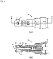
Figures 1(A) and 1(B) are diagrams showing a housing of a connector as an embodiment of the present invention,Figure 1(A) being an isometric view,Figure 1(B) being a cross sectional view taken along arrows X-X inFigure 1(A) ; -
Figures 2(A) and 2(B) are isometric views of the housing and a female contact,Figure 2(A) being an isometric view showing the housing and the female contact before plugged in,Figure 2(B) being an isometric view showing the housing and the female contact plugged in the housing; -
Figures 3(A) and 3(B) are diagrams showing the housing and the female contact plugged in the housing,Figure 3(A) being a top view,Figure 3(B) being a cross sectional view taken along arrows Y-Y inFigure 3(A) ; and -
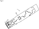
Figure 4 is an isometric view having the housing covered with an outer conductor for shielding. - Hereinafter, an embodiment of the present invention will be described.
-
Figures 1(A) and 1(B) are diagrams showing a housing of a connector as an embodiment of the present invention. Here,Figure 1(A) is an isometric view, andFigure 1(B) is a cross sectional view taken along arrows X-X inFigure 1(A) . - A mating opening 11 from which a male contact (not shown) that is a mating contact is plugged in is formed in a front end of this
housing 10. In addition, an assembly opening 12 from which a female contact 20 (seeFigure 2(A) ) that is incorporated into thishousing 10 to constitute the connector together with thishousing 10 is plugged in is formed in a rear end of thishousing 10. Furthermore, afirst confirmation window 13 is formed in thishousing 10. Thisfirst confirmation window 13 is a window for confirming that thefemale contact 20 has been plugged in to a predetermined plug-in reference position within thehousing 10. Specifically, when thefemale contact 20 is plugged in from the assembly opening 12, no part of thefemale contact 20 is visible from thefirst confirmation window 13 before thefemale contact 20 reaches the predetermined plug-in reference position. Then, when thefemale contact 20 reaches the plug-in reference position, thefront end 21 of thefemale contact 20 becomes visible from thefirst confirmation window 13. That is, thefirst confirmation window 13 is formed in a position where, if any part of thefront end 21 of thefemale contact 20 is visible, it means that thefemale contact 20 has reached the plug-in reference position having a predetermined allowable range. - In addition, an
extraction hole 14 for a manufacturing die for this housing is formed in thishousing 10. Thefemale contact 20 plugged into thishousing 10 is pressed by the mating male contact when the male contact is plugged in, and required to open thefront end 21. Therefore, thehousing 10 is required to have aspace 15 having a size allowing thefront end 21 of thefemale contact 20 to open. Theextraction hole 14 is an extraction hole for a die for forming thisspace 15. - The
front end 21 of thefemale contact 20 plugged in is also visible from thisextraction hole 14. However, thisspace 15 is required to extend to a position receding or extending rearwardly from thefront end 21 of thefemale contact 20. Assume that thisextraction hole 14 is substituted for the confirmation window. In that case, it is necessary not to judge whether or not thefront end 21 of thefemale contact 20 is visible from theextraction hole 14, but to measure a dimension of a visible part of thefemale contact 20 and judge whether or not thefemale contact 20 has been plugged in to the plug-in reference position. Therefore, in the present embodiment, thefirst confirmation window 13 is formed separately from thisextraction hole 14. -
Figures 2(A) and 2(B) are isometric views of the housing and the female contact. Here,Figure 2(A) shows the housing and the female contact before being plugged in in a plugging-in attitude toward the housing. In addition,Figure 2(B) shows the housing and the female contact plugged into the housing. - As shown in
Figure 2(A) , anelectric wire 30 used here is a coaxial cable having acore wire 31 and ashielding wire 32. Thecore wire 31 of thiselectric wire 30 is connected by crimping to thefemale contact 20. Thefemale contact 20 connected to theelectric wire 30 is plugged in from the assembly opening 12 (seeFigure 1(B) ) of thehousing 10 to a position shown inFigure 2(B) . -
Figures 3(A) and 3(B) are diagrams showing the housing and the female contact plugged into the housing.Figure 3(A) is a top view, andFigure 3(B) is a cross sectional view taken along arrows Y-Y inFigure 3(A) . - The
female contact 20 has been plugged in to a position where itsfront end 21 is visible from thefirst confirmation window 13. The fact that thefront end 21 of thefemale contact 20 is visible from thefirst confirmation window 13 confirms that thefemale contact 20 has been plugged in properly. -
Figure 4 is an isometric view in which the housing is covered with an outer conductor for shielding. - In the
connector 1 of the present embodiment, as shown inFigure 4 , the housing 10 (seeFigures 1(A) to 3(B) ) is covered with anouter conductor 40 for shielding. Thisouter conductor 40 is electrically connected to theshielding wire 32 of theelectric wire 30 shown inFigures 2(A) and 2(B) . When theconnector 1 shown inFigure 4 is assembled, an assembly procedure in which thefemale contact 20 is plugged into thehousing 10 covered with theouter conductor 40 is also conceivable. Therefore, in theconnector 1 of the present embodiment, asecond confirmation window 41 overlapping thefirst confirmation window 13 of thehousing 10 is formed in thisouter conductor 40. This enables confirmation of thefront end 21 of thefemale contact 20 plugged in to the proper position from thesecond confirmation window 41 through thefirst confirmation window 13 even when thehousing 10 is covered with theouter conductor 40. - It should be noted that, through the
connector 1 of a type provided with theouter conductor 40 has been described herein, the present invention is also applicable to a connector of a type without theouter conductor 40. - In addition, though the connector of a type provided with the
female contact 20 has been described herein, the type of the contact does not matter to the present invention, and the present invention is also applicable to a connector of a type provided with a male contact. -
- 1
- connector
- 10
- housing
- 11
- mating opening
- 12
- assembly opening
- 13
- first confirmation window
- 20
- female contact (first contact)
- 21
- front end of female contact (front end of first contact)
- 30
- electric wire
- 40
- outer conductor
- 41
- second confirmation window
Claims (2)
- A connector (1) comprising:a first contact (20) connected to an electric wire (30); anda housing (10) including:a front end having a mating opening (11) formed therein for plugging in a mating contact;a rear end having an assembly opening (12) formed therein for plugging in the first contact (20); anda first confirmation window (13) through which the first contact (20) is invisible prior to the first contact (20) reaching a predetermined plug-in reference position upon the first contact (20) being plugged in through the assembly opening (12), and through which a front end of the first contact (20) becomes visible upon the first contact (20) reaching the plug-in reference position.
- The connector (1) according to claim 1 further comprising an outer conductor (40) covering the housing (10), the outer conductor (40) having a second confirmation window (41) overlapping the first confirmation window (13).
Applications Claiming Priority (1)
| Application Number | Priority Date | Filing Date | Title |
|---|---|---|---|
| JP2019171195A JP7361550B2 (en) | 2019-09-20 | 2019-09-20 | connector |
Publications (2)
| Publication Number | Publication Date |
|---|---|
| EP3796476A1 true EP3796476A1 (en) | 2021-03-24 |
| EP3796476B1 EP3796476B1 (en) | 2022-07-13 |
Family
ID=72560466
Family Applications (1)
| Application Number | Title | Priority Date | Filing Date |
|---|---|---|---|
| EP20196672.8A Active EP3796476B1 (en) | 2019-09-20 | 2020-09-17 | Connector |
Country Status (4)
| Country | Link |
|---|---|
| US (1) | US11437738B2 (en) |
| EP (1) | EP3796476B1 (en) |
| JP (1) | JP7361550B2 (en) |
| CN (1) | CN112542738A (en) |
Families Citing this family (2)
| Publication number | Priority date | Publication date | Assignee | Title |
|---|---|---|---|---|
| JP2023049257A (en) * | 2021-09-29 | 2023-04-10 | 住友電装株式会社 | connector |
| FR3149727A1 (en) | 2023-06-06 | 2024-12-13 | Raydiall | Connector subassembly for cable with insulated electrical wires, comprising a metal body housing an electrical insulating block and central contacts each connected to a cable wire. |
Citations (2)
| Publication number | Priority date | Publication date | Assignee | Title |
|---|---|---|---|---|
| EP1168516A2 (en) * | 2000-06-27 | 2002-01-02 | Yazaki Corporation | Connector |
| JP2003223960A (en) | 2002-01-30 | 2003-08-08 | Sumitomo Wiring Syst Ltd | Connector |
Family Cites Families (32)
| Publication number | Priority date | Publication date | Assignee | Title |
|---|---|---|---|---|
| US3654592A (en) * | 1970-09-21 | 1972-04-04 | Berg Electronics Inc | Electrical connector and block |
| JP2555394Y2 (en) * | 1988-10-26 | 1997-11-19 | 日本エー・エム・ピー 株式会社 | connector |
| JP2983035B2 (en) | 1990-04-27 | 1999-11-29 | 東洋インキ製造株式会社 | Verification record and verification method using the same |
| JPH06342115A (en) * | 1993-05-31 | 1994-12-13 | Mitsumi Electric Co Ltd | Optical plug connector |
| JP2901878B2 (en) * | 1994-07-15 | 1999-06-07 | オリンパス光学工業株式会社 | Wire connector |
| JPH08250214A (en) * | 1995-03-07 | 1996-09-27 | Sumitomo Wiring Syst Ltd | Incomplete insertion detecting connector and incomplete insertion detecting method for connector |
| JP2000106239A (en) * | 1998-09-28 | 2000-04-11 | Hirose Electric Co Ltd | Electrical connector with female contacts |
| US6120333A (en) * | 1998-12-07 | 2000-09-19 | Hon Hai Precision Ind. Co., Ltd. | Electric connector with terminal retaining means |
| JP2000252016A (en) * | 1998-12-28 | 2000-09-14 | Teac Corp | Code terminal indicator and display method |
| JP2001266965A (en) * | 2000-03-17 | 2001-09-28 | Yotsugi Co Ltd | Cover for cable terminal |
| JP3719107B2 (en) | 2000-06-09 | 2005-11-24 | 住友電装株式会社 | Female terminal bracket |
| JP2003132972A (en) * | 2001-10-23 | 2003-05-09 | Matsushita Electric Works Ltd | Electric connector |
| JP4069321B2 (en) * | 2003-07-25 | 2008-04-02 | 住友電装株式会社 | Terminal insertion amount inspection device |
| JP2006107802A (en) * | 2004-10-01 | 2006-04-20 | Auto Network Gijutsu Kenkyusho:Kk | Shield connector with built-in electronic elements |
| JP2006147283A (en) * | 2004-11-18 | 2006-06-08 | Sharp Corp | connector |
| JP4708157B2 (en) | 2005-10-25 | 2011-06-22 | マスプロ電工株式会社 | Electronics |
| JP4651512B2 (en) * | 2005-11-17 | 2011-03-16 | モレックス インコーポレイテド | connector |
| JP2008027663A (en) * | 2006-07-19 | 2008-02-07 | Sato Corp | Connection structure to connector |
| JP5112981B2 (en) * | 2008-08-01 | 2013-01-09 | 株式会社オートネットワーク技術研究所 | Joint connector and method of connecting terminals using the joint connector |
| CN102063978A (en) * | 2009-11-13 | 2011-05-18 | 西安神电电器有限公司 | Direct-insert plug-in arrester with contact indicating device |
| JP2012169185A (en) * | 2011-02-15 | 2012-09-06 | Yazaki Corp | Joint connector device |
| JP5344059B2 (en) | 2011-03-18 | 2013-11-20 | 第一精工株式会社 | Electrical connector |
| CN202364234U (en) * | 2011-11-10 | 2012-08-01 | 明泰科技股份有限公司 | Optical fiber interface transceiver with inspection hole |
| US8517775B1 (en) * | 2012-02-13 | 2013-08-27 | Cheng Uei Precision Industry Co., Ltd. | Electrical connector |
| JP5973865B2 (en) * | 2012-10-10 | 2016-08-23 | 矢崎総業株式会社 | Anti-tactile connector |
| JP2014086169A (en) | 2012-10-19 | 2014-05-12 | Yazaki Corp | Pressure contact connector |
| CN203850516U (en) * | 2013-03-29 | 2014-09-24 | 日本压着端子制造株式会社 | Socket housing of socket connector and base housing of base connector |
| CN204088685U (en) * | 2014-08-12 | 2015-01-07 | 深圳市爱特姆科技有限公司 | A kind of electric power connector |
| JP6179564B2 (en) * | 2015-07-29 | 2017-08-16 | 第一精工株式会社 | Electrical connector for board connection |
| CN208690552U (en) * | 2018-05-18 | 2019-04-02 | 深圳市坚果皮科技有限公司 | a data line |
| CN208368776U (en) * | 2018-06-29 | 2019-01-11 | 深圳市大疆创新科技有限公司 | connector and handheld device |
| CN110176697B (en) * | 2019-03-27 | 2021-04-23 | 番禺得意精密电子工业有限公司 | Electrical connector |
-
2019
- 2019-09-20 JP JP2019171195A patent/JP7361550B2/en active Active
-
2020
- 2020-09-17 US US17/024,000 patent/US11437738B2/en active Active
- 2020-09-17 CN CN202010981684.3A patent/CN112542738A/en active Pending
- 2020-09-17 EP EP20196672.8A patent/EP3796476B1/en active Active
Patent Citations (2)
| Publication number | Priority date | Publication date | Assignee | Title |
|---|---|---|---|---|
| EP1168516A2 (en) * | 2000-06-27 | 2002-01-02 | Yazaki Corporation | Connector |
| JP2003223960A (en) | 2002-01-30 | 2003-08-08 | Sumitomo Wiring Syst Ltd | Connector |
Also Published As
| Publication number | Publication date |
|---|---|
| JP2021048104A (en) | 2021-03-25 |
| US11437738B2 (en) | 2022-09-06 |
| EP3796476B1 (en) | 2022-07-13 |
| US20210091482A1 (en) | 2021-03-25 |
| CN112542738A (en) | 2021-03-23 |
| JP7361550B2 (en) | 2023-10-16 |
Similar Documents
| Publication | Publication Date | Title |
|---|---|---|
| US10594057B2 (en) | Terminal fitting for coaxial connector | |
| KR101910283B1 (en) | Coaxial connector assembly | |
| US9444167B2 (en) | Terminal and terminal manufacturing method | |
| US10594056B2 (en) | Terminal fitting | |
| US4619496A (en) | Coaxial plug and jack connectors | |
| EP2375512B1 (en) | Terminal fitting and production method therefor | |
| CN100566038C (en) | Female terminal fitting is used for the blank of several terminals joint and the method that forms female terminal fitting | |
| CN105226424B (en) | Bonder terminal and the connector including the bonder terminal | |
| EP2157669A1 (en) | A connector and assembling method therefor | |
| EP2346120A1 (en) | Shield connector and production method thereof | |
| JP2003297493A (en) | Coaxial connector | |
| JP2019503576A (en) | Right angle coaxial electrical connector and method for verifying its proper assembly | |
| EP3796476B1 (en) | Connector | |
| US10116084B2 (en) | Connector | |
| CN112514168A (en) | Terminal with a terminal body | |
| CN118402147A (en) | Two-part contact element for an electrical plug connection and method for producing such a contact element | |
| CN107919564A (en) | Connector | |
| EP0475319B1 (en) | Electrical connector | |
| EP3336970B1 (en) | Electrical connector and method of assembling an electrical connector to a cable | |
| CN111834793B (en) | Connector for differential signal transmission cable and shell structure thereof | |
| US20140065879A1 (en) | F-Connector with Chamfered Lock Ring | |
| US5975948A (en) | Coaxial cable connector | |
| JP5086932B2 (en) | Electrical connector | |
| US20090170366A1 (en) | Shield sleeve for a plug connector | |
| CN113270768A (en) | Shielded electrical connector |
Legal Events
| Date | Code | Title | Description |
|---|---|---|---|
| PUAI | Public reference made under article 153(3) epc to a published international application that has entered the european phase |
Free format text: ORIGINAL CODE: 0009012 |
|
| STAA | Information on the status of an ep patent application or granted ep patent |
Free format text: STATUS: THE APPLICATION HAS BEEN PUBLISHED |
|
| AK | Designated contracting states |
Kind code of ref document: A1 Designated state(s): AL AT BE BG CH CY CZ DE DK EE ES FI FR GB GR HR HU IE IS IT LI LT LU LV MC MK MT NL NO PL PT RO RS SE SI SK SM TR |
|
| AX | Request for extension of the european patent |
Extension state: BA ME |
|
| STAA | Information on the status of an ep patent application or granted ep patent |
Free format text: STATUS: REQUEST FOR EXAMINATION WAS MADE |
|
| 17P | Request for examination filed |
Effective date: 20210906 |
|
| RBV | Designated contracting states (corrected) |
Designated state(s): AL AT BE BG CH CY CZ DE DK EE ES FI FR GB GR HR HU IE IS IT LI LT LU LV MC MK MT NL NO PL PT RO RS SE SI SK SM TR |
|
| GRAP | Despatch of communication of intention to grant a patent |
Free format text: ORIGINAL CODE: EPIDOSNIGR1 |
|
| STAA | Information on the status of an ep patent application or granted ep patent |
Free format text: STATUS: GRANT OF PATENT IS INTENDED |
|
| INTG | Intention to grant announced |
Effective date: 20220210 |
|
| GRAS | Grant fee paid |
Free format text: ORIGINAL CODE: EPIDOSNIGR3 |
|
| GRAA | (expected) grant |
Free format text: ORIGINAL CODE: 0009210 |
|
| STAA | Information on the status of an ep patent application or granted ep patent |
Free format text: STATUS: THE PATENT HAS BEEN GRANTED |
|
| AK | Designated contracting states |
Kind code of ref document: B1 Designated state(s): AL AT BE BG CH CY CZ DE DK EE ES FI FR GB GR HR HU IE IS IT LI LT LU LV MC MK MT NL NO PL PT RO RS SE SI SK SM TR |
|
| REG | Reference to a national code |
Ref country code: CH Ref legal event code: EP |
|
| REG | Reference to a national code |
Ref country code: DE Ref legal event code: R096 Ref document number: 602020003976 Country of ref document: DE |
|
| REG | Reference to a national code |
Ref country code: AT Ref legal event code: REF Ref document number: 1504748 Country of ref document: AT Kind code of ref document: T Effective date: 20220815 |
|
| REG | Reference to a national code |
Ref country code: IE Ref legal event code: FG4D |
|
| REG | Reference to a national code |
Ref country code: LT Ref legal event code: MG9D |
|
| REG | Reference to a national code |
Ref country code: NL Ref legal event code: MP Effective date: 20220713 |
|
| PG25 | Lapsed in a contracting state [announced via postgrant information from national office to epo] |
Ref country code: SE Free format text: LAPSE BECAUSE OF FAILURE TO SUBMIT A TRANSLATION OF THE DESCRIPTION OR TO PAY THE FEE WITHIN THE PRESCRIBED TIME-LIMIT Effective date: 20220713 Ref country code: RS Free format text: LAPSE BECAUSE OF FAILURE TO SUBMIT A TRANSLATION OF THE DESCRIPTION OR TO PAY THE FEE WITHIN THE PRESCRIBED TIME-LIMIT Effective date: 20220713 Ref country code: PT Free format text: LAPSE BECAUSE OF FAILURE TO SUBMIT A TRANSLATION OF THE DESCRIPTION OR TO PAY THE FEE WITHIN THE PRESCRIBED TIME-LIMIT Effective date: 20221114 Ref country code: NO Free format text: LAPSE BECAUSE OF FAILURE TO SUBMIT A TRANSLATION OF THE DESCRIPTION OR TO PAY THE FEE WITHIN THE PRESCRIBED TIME-LIMIT Effective date: 20221013 Ref country code: NL Free format text: LAPSE BECAUSE OF FAILURE TO SUBMIT A TRANSLATION OF THE DESCRIPTION OR TO PAY THE FEE WITHIN THE PRESCRIBED TIME-LIMIT Effective date: 20220713 Ref country code: LV Free format text: LAPSE BECAUSE OF FAILURE TO SUBMIT A TRANSLATION OF THE DESCRIPTION OR TO PAY THE FEE WITHIN THE PRESCRIBED TIME-LIMIT Effective date: 20220713 Ref country code: LT Free format text: LAPSE BECAUSE OF FAILURE TO SUBMIT A TRANSLATION OF THE DESCRIPTION OR TO PAY THE FEE WITHIN THE PRESCRIBED TIME-LIMIT Effective date: 20220713 Ref country code: FI Free format text: LAPSE BECAUSE OF FAILURE TO SUBMIT A TRANSLATION OF THE DESCRIPTION OR TO PAY THE FEE WITHIN THE PRESCRIBED TIME-LIMIT Effective date: 20220713 Ref country code: ES Free format text: LAPSE BECAUSE OF FAILURE TO SUBMIT A TRANSLATION OF THE DESCRIPTION OR TO PAY THE FEE WITHIN THE PRESCRIBED TIME-LIMIT Effective date: 20220713 |
|
| REG | Reference to a national code |
Ref country code: AT Ref legal event code: MK05 Ref document number: 1504748 Country of ref document: AT Kind code of ref document: T Effective date: 20220713 |
|
| PG25 | Lapsed in a contracting state [announced via postgrant information from national office to epo] |
Ref country code: PL Free format text: LAPSE BECAUSE OF FAILURE TO SUBMIT A TRANSLATION OF THE DESCRIPTION OR TO PAY THE FEE WITHIN THE PRESCRIBED TIME-LIMIT Effective date: 20220713 Ref country code: IS Free format text: LAPSE BECAUSE OF FAILURE TO SUBMIT A TRANSLATION OF THE DESCRIPTION OR TO PAY THE FEE WITHIN THE PRESCRIBED TIME-LIMIT Effective date: 20221113 Ref country code: HR Free format text: LAPSE BECAUSE OF FAILURE TO SUBMIT A TRANSLATION OF THE DESCRIPTION OR TO PAY THE FEE WITHIN THE PRESCRIBED TIME-LIMIT Effective date: 20220713 Ref country code: GR Free format text: LAPSE BECAUSE OF FAILURE TO SUBMIT A TRANSLATION OF THE DESCRIPTION OR TO PAY THE FEE WITHIN THE PRESCRIBED TIME-LIMIT Effective date: 20221014 |
|
| REG | Reference to a national code |
Ref country code: DE Ref legal event code: R097 Ref document number: 602020003976 Country of ref document: DE |
|
| PG25 | Lapsed in a contracting state [announced via postgrant information from national office to epo] |
Ref country code: SM Free format text: LAPSE BECAUSE OF FAILURE TO SUBMIT A TRANSLATION OF THE DESCRIPTION OR TO PAY THE FEE WITHIN THE PRESCRIBED TIME-LIMIT Effective date: 20220713 Ref country code: RO Free format text: LAPSE BECAUSE OF FAILURE TO SUBMIT A TRANSLATION OF THE DESCRIPTION OR TO PAY THE FEE WITHIN THE PRESCRIBED TIME-LIMIT Effective date: 20220713 Ref country code: MC Free format text: LAPSE BECAUSE OF FAILURE TO SUBMIT A TRANSLATION OF THE DESCRIPTION OR TO PAY THE FEE WITHIN THE PRESCRIBED TIME-LIMIT Effective date: 20220713 Ref country code: DK Free format text: LAPSE BECAUSE OF FAILURE TO SUBMIT A TRANSLATION OF THE DESCRIPTION OR TO PAY THE FEE WITHIN THE PRESCRIBED TIME-LIMIT Effective date: 20220713 Ref country code: CZ Free format text: LAPSE BECAUSE OF FAILURE TO SUBMIT A TRANSLATION OF THE DESCRIPTION OR TO PAY THE FEE WITHIN THE PRESCRIBED TIME-LIMIT Effective date: 20220713 Ref country code: AT Free format text: LAPSE BECAUSE OF FAILURE TO SUBMIT A TRANSLATION OF THE DESCRIPTION OR TO PAY THE FEE WITHIN THE PRESCRIBED TIME-LIMIT Effective date: 20220713 |
|
| PLBE | No opposition filed within time limit |
Free format text: ORIGINAL CODE: 0009261 |
|
| STAA | Information on the status of an ep patent application or granted ep patent |
Free format text: STATUS: NO OPPOSITION FILED WITHIN TIME LIMIT |
|
| REG | Reference to a national code |
Ref country code: BE Ref legal event code: MM Effective date: 20220930 |
|
| PG25 | Lapsed in a contracting state [announced via postgrant information from national office to epo] |
Ref country code: SK Free format text: LAPSE BECAUSE OF FAILURE TO SUBMIT A TRANSLATION OF THE DESCRIPTION OR TO PAY THE FEE WITHIN THE PRESCRIBED TIME-LIMIT Effective date: 20220713 Ref country code: EE Free format text: LAPSE BECAUSE OF FAILURE TO SUBMIT A TRANSLATION OF THE DESCRIPTION OR TO PAY THE FEE WITHIN THE PRESCRIBED TIME-LIMIT Effective date: 20220713 |
|
| 26N | No opposition filed |
Effective date: 20230414 |
|
| PG25 | Lapsed in a contracting state [announced via postgrant information from national office to epo] |
Ref country code: LU Free format text: LAPSE BECAUSE OF NON-PAYMENT OF DUE FEES Effective date: 20220917 Ref country code: AL Free format text: LAPSE BECAUSE OF FAILURE TO SUBMIT A TRANSLATION OF THE DESCRIPTION OR TO PAY THE FEE WITHIN THE PRESCRIBED TIME-LIMIT Effective date: 20220713 |
|
| PG25 | Lapsed in a contracting state [announced via postgrant information from national office to epo] |
Ref country code: IE Free format text: LAPSE BECAUSE OF NON-PAYMENT OF DUE FEES Effective date: 20220917 |
|
| PG25 | Lapsed in a contracting state [announced via postgrant information from national office to epo] |
Ref country code: SI Free format text: LAPSE BECAUSE OF FAILURE TO SUBMIT A TRANSLATION OF THE DESCRIPTION OR TO PAY THE FEE WITHIN THE PRESCRIBED TIME-LIMIT Effective date: 20220713 |
|
| PG25 | Lapsed in a contracting state [announced via postgrant information from national office to epo] |
Ref country code: BE Free format text: LAPSE BECAUSE OF NON-PAYMENT OF DUE FEES Effective date: 20220930 |
|
| PG25 | Lapsed in a contracting state [announced via postgrant information from national office to epo] |
Ref country code: IT Free format text: LAPSE BECAUSE OF FAILURE TO SUBMIT A TRANSLATION OF THE DESCRIPTION OR TO PAY THE FEE WITHIN THE PRESCRIBED TIME-LIMIT Effective date: 20220713 |
|
| PG25 | Lapsed in a contracting state [announced via postgrant information from national office to epo] |
Ref country code: CY Free format text: LAPSE BECAUSE OF FAILURE TO SUBMIT A TRANSLATION OF THE DESCRIPTION OR TO PAY THE FEE WITHIN THE PRESCRIBED TIME-LIMIT Effective date: 20220713 |
|
| REG | Reference to a national code |
Ref country code: CH Ref legal event code: PL |
|
| PG25 | Lapsed in a contracting state [announced via postgrant information from national office to epo] |
Ref country code: MK Free format text: LAPSE BECAUSE OF FAILURE TO SUBMIT A TRANSLATION OF THE DESCRIPTION OR TO PAY THE FEE WITHIN THE PRESCRIBED TIME-LIMIT Effective date: 20220713 Ref country code: HU Free format text: LAPSE BECAUSE OF FAILURE TO SUBMIT A TRANSLATION OF THE DESCRIPTION OR TO PAY THE FEE WITHIN THE PRESCRIBED TIME-LIMIT; INVALID AB INITIO Effective date: 20200917 |
|
| PG25 | Lapsed in a contracting state [announced via postgrant information from national office to epo] |
Ref country code: CH Free format text: LAPSE BECAUSE OF NON-PAYMENT OF DUE FEES Effective date: 20230930 |
|
| PG25 | Lapsed in a contracting state [announced via postgrant information from national office to epo] |
Ref country code: CH Free format text: LAPSE BECAUSE OF NON-PAYMENT OF DUE FEES Effective date: 20230930 Ref country code: BG Free format text: LAPSE BECAUSE OF FAILURE TO SUBMIT A TRANSLATION OF THE DESCRIPTION OR TO PAY THE FEE WITHIN THE PRESCRIBED TIME-LIMIT Effective date: 20220713 |
|
| PG25 | Lapsed in a contracting state [announced via postgrant information from national office to epo] |
Ref country code: MT Free format text: LAPSE BECAUSE OF FAILURE TO SUBMIT A TRANSLATION OF THE DESCRIPTION OR TO PAY THE FEE WITHIN THE PRESCRIBED TIME-LIMIT Effective date: 20220713 |
|
| GBPC | Gb: european patent ceased through non-payment of renewal fee |
Effective date: 20240917 |
|
| PG25 | Lapsed in a contracting state [announced via postgrant information from national office to epo] |
Ref country code: GB Free format text: LAPSE BECAUSE OF NON-PAYMENT OF DUE FEES Effective date: 20240917 |
|
| PGFP | Annual fee paid to national office [announced via postgrant information from national office to epo] |
Ref country code: DE Payment date: 20250702 Year of fee payment: 6 |
|
| PGFP | Annual fee paid to national office [announced via postgrant information from national office to epo] |
Ref country code: FR Payment date: 20250708 Year of fee payment: 6 |
|
| PG25 | Lapsed in a contracting state [announced via postgrant information from national office to epo] |
Ref country code: TR Free format text: LAPSE BECAUSE OF FAILURE TO SUBMIT A TRANSLATION OF THE DESCRIPTION OR TO PAY THE FEE WITHIN THE PRESCRIBED TIME-LIMIT Effective date: 20220713 |