EP3796475B1 - Charging coupling - Google Patents
Charging coupling Download PDFInfo
- Publication number
- EP3796475B1 EP3796475B1 EP20197024.1A EP20197024A EP3796475B1 EP 3796475 B1 EP3796475 B1 EP 3796475B1 EP 20197024 A EP20197024 A EP 20197024A EP 3796475 B1 EP3796475 B1 EP 3796475B1
- Authority
- EP
- European Patent Office
- Prior art keywords
- charging
- fixing
- contact portion
- elastic terminal
- plate
- Prior art date
- Legal status (The legal status is an assumption and is not a legal conclusion. Google has not performed a legal analysis and makes no representation as to the accuracy of the status listed.)
- Active
Links
Images


Classifications
-
- H—ELECTRICITY
- H01—ELECTRIC ELEMENTS
- H01R—ELECTRICALLY-CONDUCTIVE CONNECTIONS; STRUCTURAL ASSOCIATIONS OF A PLURALITY OF MUTUALLY-INSULATED ELECTRICAL CONNECTING ELEMENTS; COUPLING DEVICES; CURRENT COLLECTORS
- H01R13/00—Details of coupling devices of the kinds covered by groups H01R12/70 or H01R24/00 - H01R33/00
- H01R13/02—Contact members
- H01R13/20—Pins, blades, or sockets shaped, or provided with separate member, to retain co-operating parts together
-
- H—ELECTRICITY
- H02—GENERATION; CONVERSION OR DISTRIBUTION OF ELECTRIC POWER
- H02J—ELECTRIC POWER NETWORKS; CIRCUIT ARRANGEMENTS OR SYSTEMS FOR SUPPLYING OR DISTRIBUTING ELECTRIC POWER; SYSTEMS FOR STORING ELECTRIC ENERGY
- H02J7/00—Circuit arrangements for charging or discharging batteries or for supplying loads from batteries
- H02J7/70—Circuit arrangements for charging or discharging batteries or for supplying loads from batteries characterised by the mechanical construction
-
- A—HUMAN NECESSITIES
- A01—AGRICULTURE; FORESTRY; ANIMAL HUSBANDRY; HUNTING; TRAPPING; FISHING
- A01D—HARVESTING; MOWING
- A01D34/00—Mowers; Mowing apparatus of harvesters
- A01D34/001—Accessories not otherwise provided for
-
- A—HUMAN NECESSITIES
- A01—AGRICULTURE; FORESTRY; ANIMAL HUSBANDRY; HUNTING; TRAPPING; FISHING
- A01D—HARVESTING; MOWING
- A01D69/00—Driving mechanisms or parts thereof for harvesters or mowers
- A01D69/02—Driving mechanisms or parts thereof for harvesters or mowers electric
-
- H—ELECTRICITY
- H01—ELECTRIC ELEMENTS
- H01R—ELECTRICALLY-CONDUCTIVE CONNECTIONS; STRUCTURAL ASSOCIATIONS OF A PLURALITY OF MUTUALLY-INSULATED ELECTRICAL CONNECTING ELEMENTS; COUPLING DEVICES; CURRENT COLLECTORS
- H01R13/00—Details of coupling devices of the kinds covered by groups H01R12/70 or H01R24/00 - H01R33/00
- H01R13/02—Contact members
- H01R13/04—Pins or blades for co-operation with sockets
- H01R13/05—Resilient pins or blades
-
- H—ELECTRICITY
- H01—ELECTRIC ELEMENTS
- H01R—ELECTRICALLY-CONDUCTIVE CONNECTIONS; STRUCTURAL ASSOCIATIONS OF A PLURALITY OF MUTUALLY-INSULATED ELECTRICAL CONNECTING ELEMENTS; COUPLING DEVICES; CURRENT COLLECTORS
- H01R13/00—Details of coupling devices of the kinds covered by groups H01R12/70 or H01R24/00 - H01R33/00
- H01R13/02—Contact members
- H01R13/10—Sockets for co-operation with pins or blades
- H01R13/11—Resilient sockets
-
- H—ELECTRICITY
- H01—ELECTRIC ELEMENTS
- H01R—ELECTRICALLY-CONDUCTIVE CONNECTIONS; STRUCTURAL ASSOCIATIONS OF A PLURALITY OF MUTUALLY-INSULATED ELECTRICAL CONNECTING ELEMENTS; COUPLING DEVICES; CURRENT COLLECTORS
- H01R13/00—Details of coupling devices of the kinds covered by groups H01R12/70 or H01R24/00 - H01R33/00
- H01R13/02—Contact members
- H01R13/20—Pins, blades, or sockets shaped, or provided with separate member, to retain co-operating parts together
- H01R13/213—Pins, blades, or sockets shaped, or provided with separate member, to retain co-operating parts together by bayonet connection
-
- H—ELECTRICITY
- H01—ELECTRIC ELEMENTS
- H01R—ELECTRICALLY-CONDUCTIVE CONNECTIONS; STRUCTURAL ASSOCIATIONS OF A PLURALITY OF MUTUALLY-INSULATED ELECTRICAL CONNECTING ELEMENTS; COUPLING DEVICES; CURRENT COLLECTORS
- H01R13/00—Details of coupling devices of the kinds covered by groups H01R12/70 or H01R24/00 - H01R33/00
- H01R13/02—Contact members
- H01R13/26—Pin or blade contacts for sliding co-operation on one side only
-
- H—ELECTRICITY
- H01—ELECTRIC ELEMENTS
- H01R—ELECTRICALLY-CONDUCTIVE CONNECTIONS; STRUCTURAL ASSOCIATIONS OF A PLURALITY OF MUTUALLY-INSULATED ELECTRICAL CONNECTING ELEMENTS; COUPLING DEVICES; CURRENT COLLECTORS
- H01R13/00—Details of coupling devices of the kinds covered by groups H01R12/70 or H01R24/00 - H01R33/00
- H01R13/40—Securing contact members in or to a base or case; Insulating of contact members
- H01R13/42—Securing in a demountable manner
- H01R13/428—Securing in a demountable manner by resilient locking means on the contact members; by locking means on resilient contact members
-
- H—ELECTRICITY
- H01—ELECTRIC ELEMENTS
- H01R—ELECTRICALLY-CONDUCTIVE CONNECTIONS; STRUCTURAL ASSOCIATIONS OF A PLURALITY OF MUTUALLY-INSULATED ELECTRICAL CONNECTING ELEMENTS; COUPLING DEVICES; CURRENT COLLECTORS
- H01R13/00—Details of coupling devices of the kinds covered by groups H01R12/70 or H01R24/00 - H01R33/00
- H01R13/62—Means for facilitating engagement or disengagement of coupling parts or for holding them in engagement
- H01R13/629—Additional means for facilitating engagement or disengagement of coupling parts, e.g. aligning or guiding means, levers, gas pressure electrical locking indicators, manufacturing tolerances
- H01R13/631—Additional means for facilitating engagement or disengagement of coupling parts, e.g. aligning or guiding means, levers, gas pressure electrical locking indicators, manufacturing tolerances for engagement only
-
- A—HUMAN NECESSITIES
- A01—AGRICULTURE; FORESTRY; ANIMAL HUSBANDRY; HUNTING; TRAPPING; FISHING
- A01D—HARVESTING; MOWING
- A01D2101/00—Lawn-mowers
-
- B—PERFORMING OPERATIONS; TRANSPORTING
- B60—VEHICLES IN GENERAL
- B60L—PROPULSION OF ELECTRICALLY-PROPELLED VEHICLES; SUPPLYING ELECTRIC POWER FOR AUXILIARY EQUIPMENT OF ELECTRICALLY-PROPELLED VEHICLES; ELECTRODYNAMIC BRAKE SYSTEMS FOR VEHICLES IN GENERAL; MAGNETIC SUSPENSION OR LEVITATION FOR VEHICLES; MONITORING OPERATING VARIABLES OF ELECTRICALLY-PROPELLED VEHICLES; ELECTRIC SAFETY DEVICES FOR ELECTRICALLY-PROPELLED VEHICLES
- B60L53/00—Methods of charging batteries, specially adapted for electric vehicles; Charging stations or on-board charging equipment therefor; Exchange of energy storage elements in electric vehicles
- B60L53/10—Methods of charging batteries, specially adapted for electric vehicles; Charging stations or on-board charging equipment therefor; Exchange of energy storage elements in electric vehicles characterised by the energy transfer between the charging station and the vehicle
- B60L53/14—Conductive energy transfer
- B60L53/16—Connectors, e.g. plugs or sockets, specially adapted for charging electric vehicles
-
- H—ELECTRICITY
- H01—ELECTRIC ELEMENTS
- H01R—ELECTRICALLY-CONDUCTIVE CONNECTIONS; STRUCTURAL ASSOCIATIONS OF A PLURALITY OF MUTUALLY-INSULATED ELECTRICAL CONNECTING ELEMENTS; COUPLING DEVICES; CURRENT COLLECTORS
- H01R2103/00—Two poles
-
- H—ELECTRICITY
- H01—ELECTRIC ELEMENTS
- H01R—ELECTRICALLY-CONDUCTIVE CONNECTIONS; STRUCTURAL ASSOCIATIONS OF A PLURALITY OF MUTUALLY-INSULATED ELECTRICAL CONNECTING ELEMENTS; COUPLING DEVICES; CURRENT COLLECTORS
- H01R2201/00—Connectors or connections adapted for particular applications
- H01R2201/26—Connectors or connections adapted for particular applications for vehicles
-
- H—ELECTRICITY
- H01—ELECTRIC ELEMENTS
- H01R—ELECTRICALLY-CONDUCTIVE CONNECTIONS; STRUCTURAL ASSOCIATIONS OF A PLURALITY OF MUTUALLY-INSULATED ELECTRICAL CONNECTING ELEMENTS; COUPLING DEVICES; CURRENT COLLECTORS
- H01R24/00—Two-part coupling devices, or either of their cooperating parts, characterised by their overall structure
- H01R24/66—Two-part coupling devices, or either of their cooperating parts, characterised by their overall structure with pins, blades or analogous contacts and secured to apparatus or structure, e.g. to a wall
- H01R24/68—Two-part coupling devices, or either of their cooperating parts, characterised by their overall structure with pins, blades or analogous contacts and secured to apparatus or structure, e.g. to a wall mounted on directly pluggable apparatus
-
- Y—GENERAL TAGGING OF NEW TECHNOLOGICAL DEVELOPMENTS; GENERAL TAGGING OF CROSS-SECTIONAL TECHNOLOGIES SPANNING OVER SEVERAL SECTIONS OF THE IPC; TECHNICAL SUBJECTS COVERED BY FORMER USPC CROSS-REFERENCE ART COLLECTIONS [XRACs] AND DIGESTS
- Y02—TECHNOLOGIES OR APPLICATIONS FOR MITIGATION OR ADAPTATION AGAINST CLIMATE CHANGE
- Y02T—CLIMATE CHANGE MITIGATION TECHNOLOGIES RELATED TO TRANSPORTATION
- Y02T10/00—Road transport of goods or passengers
- Y02T10/60—Other road transportation technologies with climate change mitigation effect
- Y02T10/70—Energy storage systems for electromobility, e.g. batteries
Definitions
- the present invention relates to a robotic garden tools, in particular to a charging coupling for connecting a robotic garden tool with a charging station.
- a robotic lawnmower is an autonomous robotic garden tool, which uses a battery as a power source. Based on the operating load and duration, the battery of the robotic lawnmower may get discharged periodically. A battery power level may be continuously monitored to identify the need of charging the battery by a charging coupling. It may be required to charge the battery in case the battery power level falls below a threshold power level during operation.
- an arrangement for charging the battery of the robotic lawnmower involves a metal plate mounted to the robotic lawnmower and a charging terminal with at last two resilient contacting bars mounted to the charging coupling.
- the electric current may be transferred between the charging contacts of the metal plate and the contacting bars of the charging terminal to charge the battery of the robotic lawnmower.
- electric current may be transferred from the contacting bars of the charging station to the metal plate of the robotic lawnmower.
- the charging terminal is configured with an L shape and located at the same height and the contacting bars bend upwardly from the charging terminal, such that the metal plate may not contact with the contacting bars of the charging terminal in a sufficient manner when the contacting bars lose elasticity after long-term misaligned and the electrical connection between the metal plate and the charging terminal may not be achieved.
- EP 591732 discloses an electrical connector system comprising mateable first and second connectors.
- the connectors are provided with terminals each having contact portions engageable with contact portions of the terminal of the other connector.
- the contact portions of the terminals of at least one of the connectors are at angles to the mating direction to define a generally V-shaped engaging configuration.
- the contact portions of the terminals of at least one of the connectors are resilient.
- the object of the present invention is to provide a charging coupling for easily and accurately connecting a robotic garden tool to a charging station for achieving a stable electrical connection between the robotic garden tool and the charging station.
- the beneficial effect is that it is convenient to fix the third elastic terminal and the fourth elastic terminal and prevent the third elastic terminal and the fourth elastic terminal from falling off.
- a robotic device embodied as a robotic mower, is configured to move autonomously with in a working area. It is provided with an internal and rechargeable power supply, such as a battery. When the robotic mower is docked to a charging station, the battery could be charged through a charging coupling.
- an embodiment of the present invention provides a charging coupling, which comprises a first charging assembly 10 and a second charging assembly 20 adapted to the first charging assembly.
- a purpose of a charging coupling is to receive electric current from the charging station and forward it to the battery.
- the first charging assembly 10 is mounted on one of the robotic mowers or charging stations and the second charging assembly 20 is mounted on the other.
- the first charging assembly 10 has a symmetrical structure, and the first charging assembly 10 is provided with an accommodating cavity 11.
- the accommodating cavity 11 is provided with a first elastic terminal assembly 12 and a second elastic terminal assembly 13.
- the first elastic terminal assembly 12 comprises a first groove 121 and a first elastic terminal 122, and the first groove 121 is formed in the accommodating cavity 11.
- the first elastic terminal 122 is fixed in the first groove 121.
- the second elastic terminal assembly 13 comprises a second groove 131 and a second elastic terminal 132, and the second groove 131 is formed in the accommodating cavity 11.
- the second elastic terminal 132 is fixed in the second groove 131.
- a receiving space 14 is formed between the first elastic terminal 122 and the second elastic terminal 132.
- a tapered opening 15 is provided at one side of the first charging assembly 10, which communicates with the receiving space 14.
- a first mounting portion 16 is provided at a side of the first charging assembly 10 opposite to the tapered opening 15.
- the first mounting portion 16 is installed on the charging station or the robotic device.
- the first elastic terminal 122 comprises a first fixing portion 1221 and a first contact portion 1222
- the first contact portion 1222 comprises a first initial contact portion 12221 and a first charging contact portion 12222.
- the first charging contact portion 12222 is connected to the first fixing portion 1221 through the first initial contact portion 12221.
- the first fixing portion 1221 is fixed in the first groove 121
- the first contact portion 1222 also comprises a first bent tail portion 12223 which is connected to the first charging contact portion 12222.
- the first fixing portion 1221 and the first initial contact portion 12221 form a first rounded corner (not designated in the figure). The angle of the first rounded corner is less than 90 degrees.
- the first initial contact portion 12221 and the first charging contact portion 12222 form a second rounded corner (not designated in the figure).
- the angle of the second rounded corner is greater than 90 degrees and less than 180 degrees.
- the first bent tail portion 12223 faces away from the receiving space 14.
- the angle of the rounded corner should be understood as the angle at which the extension lines of the two sides of the rounded corner intersect.
- the second elastic terminal 13 and the first elastic terminal 12 have the same structure.
- the second elastic terminal 13 comprises a second fixing portion and a second contact portion
- the second contact portion comprises a second initial contact portion and a second charging contact portion.
- the second charging contact portion is connected to the second fixing portion through the second initial contact portion, and the second fixing portion is fixed to the second groove.
- the second contact portion further comprises a second bent tail portion.
- the second bent tail portion is connected to the second charging contact portion.
- a third rounded corner is formed between the second fixing portion and the second initial contact portion. The angle of the third rounded corner is less than 90 degrees.
- the second initial contact portion and the second charging contact portion form a fourth rounded corner, and the angle of the fourth rounded corner angle is greater than 90 degrees and less than 180 degrees.
- the second bent tail portion faces away from the receiving space 14.
- the angle of the rounded corner should be understood as the angle at which the extension lines of the two sides of the rounded corner intersect. Since the second elastic terminal 13 has the same structure as the first elastic terminal 12, it is not shown in the figures.
- both the first fixing part 1221 and the second fixing part are provided with a first threading hole.
- the first threading hole is used for connecting with an electrical cord.
- the first fixing portion 1221 is parallel to the second fixing portion.
- the angle between the first charging contact portion 12222 and the second charging contact portion is smaller than that between the first initial contact portion 12221 and the second initial contact portion.
- the angle between the first initial contact portion 12221 and the second initial contact portion is smaller than the angle of the tapered opening.
- the angle between the first charging contact portion 12222 and the second charging contact portion should be understood as the angle at which the extension lines of the two intersect.
- the angle between the first initial contact portion 12221 and the second initial contact portion should be understood as the angle at which the extension lines of the two intersect.
- the angle of the tapered opening should be understood as the angle at which the extension lines of the two hypotenuses of the tapered opening intersect.
- the second charging assembly 20 has a symmetrical structure.
- One side of the second charging assembly 20 is provided with a protrusion 21, and a second mounting portion 22 is provided at the opposite side of the protrusion 21.
- the protrusion 21 is connected to the second mounting portion 22 through a tapered portion 23.
- a third elastic terminal 24 and a fourth elastic terminal 25 are disposed on the protrusion 21.
- the second mounting portion 22 is installed on the charging station or the robotic device.
- the robotic device is a robotic mower.
- the third elastic terminal 24 is hook-shaped.
- the third elastic terminal 24 comprises a third fixing portion 241 and a first hook portion 242.
- the third fixing portion 241 is provided with a first convex portion 243 and a first fixing port 244.
- the first convex portion 243 is located at one end of the third fixing portion 241 connected to the first hook portion 242, and the first convex portion 243 is located at the end of the third fixing portion 241 opposite to the side of the first hook portion 242.
- the first fixing port 244 is located at an end of the third fixing portion 241 facing away from the first hook portion 242.
- the structure of the fourth elastic terminal 25 is the same as the structure of the third elastic terminal 24.
- the fourth elastic terminal comprises a fourth fixing portion and a second hook portion.
- the fourth fixing portion is provided with a second convex portion and a second fixing port.
- the second convex portion is located at one end of the fourth fixing portion connected to the second hook portion, and the second convex portion is located at the end of the fourth fixing portion opposite to the side of the second hook portion.
- the second fixing port is located at an end of the fourth fixing portion away from the second hook portion. Since the fourth elastic terminal 25 has the same structure as the third elastic terminal 24, it is not shown in the figures.
- both the third fixing portion 24 and the fourth fixing portion 25 are provided with a second threading hole, which is used for connecting with an electrical cord.
- the protrusion 21 comprises a terminal fixing assembly 211, a lower cover plate 212 and an upper cover plate (not shown in the figure).
- the terminal fixing assembly 211 is disposed between the lower cover plate 212 and the upper cover plate (not shown in the figure).
- the terminal fixing assembly 211 comprises a first fixing plate 2111, a second fixing plate 2112, and a built-in plate 2113.
- the built-in plate 2113 is located between the first fixing plate 2111 and the second fixing plate 2112.
- a first embedded groove 2114 is located between the first fixing plate 2111 and the built-in plate 2113, and a first fixing buckle 2115 is provided on one side of the first fixing plate 2111 facing away from the built-in plate 2113.
- the first hook portion 242 is disposed in the first embedded groove 2114, and the first fixing port 244 is detachably connected with the first fixing buckle 2115.
- a second embedded groove 2116 is located between the second fixing plate 2112 and the built-in plate 2113.
- a second fixing buckle (not marked in the figure) is provided on one side of the second fixing plate 2112 facing away from the built-in plate 2113. The second hook portion (not marked in the figure) is received in the second embedded groove 2116, and the second fixing port (not marked in the figure) is detachably connected with the second fixing buckle (not marked in the figure).
- the first hook portion 242 is provided with a first blocking opening 245.
- a first baffle is provided in the first embedded groove 2114, and the first baffle is matched with the first blocking opening 245, so the first hook portion 242 is prevented from moving up and down.
- the second hook portion is provided with a second blocking opening, and the second embedded groove is provided with a second baffle. The second baffle is received in the second blocking opening to prevent the second hook portion from moving up and down.
- the first fixed buckle 2115 has an inclined surface 21151 and a vertical surface 21152 which are located on opposite sides of the first fixed buckle 2115, and the inclined surface 21151 faces the first hook portion 242.
- the inclined surface 21151 facilitates the first fixing buckle 2115 to be inserted into the first fixing port 244, and the vertical surface 21152 prevents the first fixing buckle 2115 from being separated from the first fixing port 244.
- the structure of the second fixing buckle is the same as that of the first fixed buckle.
- the distance between the first charging contact portion 12222 and the second charging contact portion 1321 is smaller than the distance between the third elastic terminal 24 and the fourth elastic terminal 25.
- the second charging assembly 20 is inserted into the first charging assembly 10 along the X-direction.
- the third elastic terminal 24 is in elastic contact with the first initial contact portion 12221
- the fourth elastic terminal 25 is in elastic contact with the second initial contact portion 1322.
- the second charging assembly 20 is inserted into the first charging assembly 10 along the X-direction.
- the protrusion 21 is inserted into the receiving space 14.
- the connecting portion between the first initial contact portion 12221 and the first charging contact portion 12222 is elastic to the third fixing portion 241, and the first charging contact portion 12222 is in elastic contact with the first convex portion 243.
- the connecting portion between the second initial contact portion 1322 and the second charging contact portion 1321 is in elastic contact with the fourth fixing portion 251, and the second charging contact portion 1321 is in elastic contact with the second convex portion 253.
- the tapered portion 23 matches the shape of the tapered opening 15.
- the first elastic terminal 122 and the third elastic terminal 24 are in elastic contact, and there are two contact portions between the first elastic terminal 122 and the third elastic terminal 24.
- the connecting portion of the first initial contact portion 12221 and the first charging contact portion 12222 jams the first convex portion.
- the second elastic terminal and the fourth elastic terminal are in elastic contact, and there are two contact portions between the second elastic terminal and the fourth elastic terminal.
- the connecting portion between the second initial contact portion and the second charging contact portion jams the second convex portion. This kind of design not only ensures the stability of the contact, but also prevents the second charging assembly from falling off from the first charging assembly.
- the first elastic terminal 122, the second elastic terminal, the third elastic terminal 24, and the fourth elastic terminal are all bent metal sheets.
Landscapes
- Life Sciences & Earth Sciences (AREA)
- Environmental Sciences (AREA)
- Engineering & Computer Science (AREA)
- Power Engineering (AREA)
- Charge And Discharge Circuits For Batteries Or The Like (AREA)
- Secondary Cells (AREA)
Description
- The present invention relates to a robotic garden tools, in particular to a charging coupling for connecting a robotic garden tool with a charging station.
- The robotic garden tools, such as, but not limited to, robotic lawnmowers are widely used for grass cutting applications in a lawn. Typically, a robotic lawnmower is an autonomous robotic garden tool, which uses a battery as a power source. Based on the operating load and duration, the battery of the robotic lawnmower may get discharged periodically. A battery power level may be continuously monitored to identify the need of charging the battery by a charging coupling. It may be required to charge the battery in case the battery power level falls below a threshold power level during operation.
- Typically, an arrangement for charging the battery of the robotic lawnmower involves a metal plate mounted to the robotic lawnmower and a charging terminal with at last two resilient contacting bars mounted to the charging coupling. The electric current may be transferred between the charging contacts of the metal plate and the contacting bars of the charging terminal to charge the battery of the robotic lawnmower. In other words, electric current may be transferred from the contacting bars of the charging station to the metal plate of the robotic lawnmower.
- However, in this arrangement, the charging terminal is configured with an L shape and located at the same height and the contacting bars bend upwardly from the charging terminal, such that the metal plate may not contact with the contacting bars of the charging terminal in a sufficient manner when the contacting bars lose elasticity after long-term misaligned and the electrical connection between the metal plate and the charging terminal may not be achieved.
-
EP 591732 - Therefore, it is necessary to provide an improved system to charge a robotic garden tool, which will overcome the disadvantages mentioned above.
- The object of the present invention is to provide a charging coupling for easily and accurately connecting a robotic garden tool to a charging station for achieving a stable electrical connection between the robotic garden tool and the charging station.
- In order to achieve the above objective, a charging coupling for a robotic device according to claim 1 is accomplished.
- The beneficial effect is that it is convenient to fix the third elastic terminal and the fourth elastic terminal and prevent the third elastic terminal and the fourth elastic terminal from falling off.
- Preferred embodiments of the invention are defined by the dependent claims 2 to 7.
-
-
FIG. 1 is a cross-sectional view of a first charging assembly of a charging coupling according to the present invention. -
FIG. 2 is a perspective view of a first elastic terminal of the present invention. -
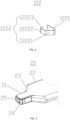
FIG. 3 is a schematic structure diagram of the second charging assembly of the present invention. -
FIG. 4 is a schematic structure diagram of the third elastic terminal of the present invention. -
FIG. 5 is a cross-sectional view of the second charging assembly of the present invention. -
FIG. 6 is a schematic structural diagram of the first fixing buckle of the present invention. -
FIG. 7 is a schematic diagram of the first charging assembly and the second charging assembly in the first using process of the present invention. -
FIG. 8 is a schematic diagram of the first charging assembly and the second charging assembly in the second using process of the present invention. - A robotic device, embodied as a robotic mower, is configured to move autonomously with in a working area. It is provided with an internal and rechargeable power supply, such as a battery. When the robotic mower is docked to a charging station, the battery could be charged through a charging coupling. In view of the problems in the prior art, an embodiment of the present invention provides a charging coupling, which comprises a
first charging assembly 10 and asecond charging assembly 20 adapted to the first charging assembly. A purpose of a charging coupling is to receive electric current from the charging station and forward it to the battery. Thefirst charging assembly 10 is mounted on one of the robotic mowers or charging stations and thesecond charging assembly 20 is mounted on the other. - Refer to
FIG. 1 now, in an embodiment of the present invention, thefirst charging assembly 10 has a symmetrical structure, and thefirst charging assembly 10 is provided with anaccommodating cavity 11. Theaccommodating cavity 11 is provided with a firstelastic terminal assembly 12 and a second elastic terminal assembly 13. The firstelastic terminal assembly 12 comprises a first groove 121 and a firstelastic terminal 122, and the first groove 121 is formed in theaccommodating cavity 11. The firstelastic terminal 122 is fixed in the first groove 121. The second elastic terminal assembly 13 comprises asecond groove 131 and a secondelastic terminal 132, and thesecond groove 131 is formed in theaccommodating cavity 11. The secondelastic terminal 132 is fixed in thesecond groove 131. Areceiving space 14 is formed between the firstelastic terminal 122 and the secondelastic terminal 132. Atapered opening 15 is provided at one side of thefirst charging assembly 10, which communicates with thereceiving space 14. Afirst mounting portion 16 is provided at a side of thefirst charging assembly 10 opposite to thetapered opening 15. - In some embodiments of the present invention, the
first mounting portion 16 is installed on the charging station or the robotic device. - Refer to
FIG. 1 andFIG. 2 now, the firstelastic terminal 122 comprises afirst fixing portion 1221 and afirst contact portion 1222, and thefirst contact portion 1222 comprises a firstinitial contact portion 12221 and a firstcharging contact portion 12222. The firstcharging contact portion 12222 is connected to thefirst fixing portion 1221 through the firstinitial contact portion 12221. Thefirst fixing portion 1221 is fixed in the first groove 121, and thefirst contact portion 1222 also comprises a firstbent tail portion 12223 which is connected to the firstcharging contact portion 12222. Thefirst fixing portion 1221 and the firstinitial contact portion 12221 form a first rounded corner (not designated in the figure). The angle of the first rounded corner is less than 90 degrees. The firstinitial contact portion 12221 and the firstcharging contact portion 12222 form a second rounded corner (not designated in the figure). The angle of the second rounded corner is greater than 90 degrees and less than 180 degrees. The firstbent tail portion 12223 faces away from thereceiving space 14. The angle of the rounded corner should be understood as the angle at which the extension lines of the two sides of the rounded corner intersect. - In some embodiments of the present invention, the second elastic terminal 13 and the first
elastic terminal 12 have the same structure. Specifically, the second elastic terminal 13 comprises a second fixing portion and a second contact portion, and the second contact portion comprises a second initial contact portion and a second charging contact portion. The second charging contact portion is connected to the second fixing portion through the second initial contact portion, and the second fixing portion is fixed to the second groove. The second contact portion further comprises a second bent tail portion. The second bent tail portion is connected to the second charging contact portion. A third rounded corner is formed between the second fixing portion and the second initial contact portion. The angle of the third rounded corner is less than 90 degrees. The second initial contact portion and the second charging contact portion form a fourth rounded corner, and the angle of the fourth rounded corner angle is greater than 90 degrees and less than 180 degrees. The second bent tail portion faces away from the receivingspace 14. The angle of the rounded corner should be understood as the angle at which the extension lines of the two sides of the rounded corner intersect. Since the second elastic terminal 13 has the same structure as the firstelastic terminal 12, it is not shown in the figures. - In some embodiments of the present invention, both the
first fixing part 1221 and the second fixing part are provided with a first threading hole. The first threading hole is used for connecting with an electrical cord. - In some embodiments of the present invention, the
first fixing portion 1221 is parallel to the second fixing portion. The angle between the firstcharging contact portion 12222 and the second charging contact portion is smaller than that between the firstinitial contact portion 12221 and the second initial contact portion. The angle between the firstinitial contact portion 12221 and the second initial contact portion is smaller than the angle of the tapered opening. The angle between the firstcharging contact portion 12222 and the second charging contact portion should be understood as the angle at which the extension lines of the two intersect. The angle between the firstinitial contact portion 12221 and the second initial contact portion should be understood as the angle at which the extension lines of the two intersect. The angle of the tapered opening should be understood as the angle at which the extension lines of the two hypotenuses of the tapered opening intersect. - Refer to
FIG. 3 , in an embodiment of the present invention, thesecond charging assembly 20 has a symmetrical structure. One side of thesecond charging assembly 20 is provided with aprotrusion 21, and a second mountingportion 22 is provided at the opposite side of theprotrusion 21. Theprotrusion 21 is connected to the second mountingportion 22 through a taperedportion 23. A thirdelastic terminal 24 and a fourthelastic terminal 25 are disposed on theprotrusion 21. - In some embodiments of the present invention, the second mounting
portion 22 is installed on the charging station or the robotic device. - In some specific embodiments of the present invention, the robotic device is a robotic mower.
- Refer to
FIG. 4 , the thirdelastic terminal 24 is hook-shaped. The thirdelastic terminal 24 comprises athird fixing portion 241 and afirst hook portion 242. Thethird fixing portion 241 is provided with a firstconvex portion 243 and a first fixingport 244. The firstconvex portion 243 is located at one end of thethird fixing portion 241 connected to thefirst hook portion 242, and the firstconvex portion 243 is located at the end of thethird fixing portion 241 opposite to the side of thefirst hook portion 242. The first fixingport 244 is located at an end of thethird fixing portion 241 facing away from thefirst hook portion 242. - In some embodiments of the present invention, the structure of the fourth
elastic terminal 25 is the same as the structure of the thirdelastic terminal 24. Specifically, the fourth elastic terminal comprises a fourth fixing portion and a second hook portion. The fourth fixing portion is provided with a second convex portion and a second fixing port. The second convex portion is located at one end of the fourth fixing portion connected to the second hook portion, and the second convex portion is located at the end of the fourth fixing portion opposite to the side of the second hook portion. The second fixing port is located at an end of the fourth fixing portion away from the second hook portion. Since the fourthelastic terminal 25 has the same structure as the thirdelastic terminal 24, it is not shown in the figures. - In some embodiments of the present invention, both the third fixing
portion 24 and the fourth fixingportion 25 are provided with a second threading hole, which is used for connecting with an electrical cord. - Referring to
FIG. 3 to FIG. 5 , theprotrusion 21 comprises aterminal fixing assembly 211, alower cover plate 212 and an upper cover plate (not shown in the figure). Theterminal fixing assembly 211 is disposed between thelower cover plate 212 and the upper cover plate (not shown in the figure). Theterminal fixing assembly 211 comprises afirst fixing plate 2111, asecond fixing plate 2112, and a built-inplate 2113. The built-inplate 2113 is located between thefirst fixing plate 2111 and thesecond fixing plate 2112. A first embeddedgroove 2114 is located between thefirst fixing plate 2111 and the built-inplate 2113, and afirst fixing buckle 2115 is provided on one side of thefirst fixing plate 2111 facing away from the built-inplate 2113. Thefirst hook portion 242 is disposed in the first embeddedgroove 2114, and the first fixingport 244 is detachably connected with thefirst fixing buckle 2115. A second embeddedgroove 2116 is located between thesecond fixing plate 2112 and the built-inplate 2113. A second fixing buckle (not marked in the figure) is provided on one side of thesecond fixing plate 2112 facing away from the built-inplate 2113. The second hook portion (not marked in the figure) is received in the second embeddedgroove 2116, and the second fixing port (not marked in the figure) is detachably connected with the second fixing buckle (not marked in the figure). - In some embodiments of the present invention, the
first hook portion 242 is provided with afirst blocking opening 245. A first baffle is provided in the first embeddedgroove 2114, and the first baffle is matched with thefirst blocking opening 245, so thefirst hook portion 242 is prevented from moving up and down. The second hook portion is provided with a second blocking opening, and the second embedded groove is provided with a second baffle. The second baffle is received in the second blocking opening to prevent the second hook portion from moving up and down. - Referring to
FIG. 6 , the first fixedbuckle 2115 has aninclined surface 21151 and avertical surface 21152 which are located on opposite sides of the first fixedbuckle 2115, and theinclined surface 21151 faces thefirst hook portion 242. Theinclined surface 21151 facilitates thefirst fixing buckle 2115 to be inserted into the first fixingport 244, and thevertical surface 21152 prevents thefirst fixing buckle 2115 from being separated from the first fixingport 244. The structure of the second fixing buckle is the same as that of the first fixed buckle. - Referring to
FIG. 1 ,FIG. 2 ,FIG. 3 andFIG. 7 , the distance between the firstcharging contact portion 12222 and the secondcharging contact portion 1321 is smaller than the distance between the thirdelastic terminal 24 and the fourthelastic terminal 25. Thesecond charging assembly 20 is inserted into the first chargingassembly 10 along the X-direction. During the first using process of the charging coupling, the thirdelastic terminal 24 is in elastic contact with the firstinitial contact portion 12221, and the fourthelastic terminal 25 is in elastic contact with the secondinitial contact portion 1322. When thesecond charging assembly 20 is inserted into the first chargingassembly 10 along the X direction, since the opening of the taperedopening 15 is larger, theprotrusion 21 is easier to insert into the taperedopening 15. Theprotrusion 21 is guided through theconical opening 15 into the receivingspace 14. - Refer to
FIG. 1 ,FIG. 2 ,FIG. 4 , andFIG. 8 , thesecond charging assembly 20 is inserted into the first chargingassembly 10 along the X-direction. During the second using process of charging coupling, theprotrusion 21 is inserted into the receivingspace 14. The connecting portion between the firstinitial contact portion 12221 and the firstcharging contact portion 12222 is elastic to thethird fixing portion 241, and the firstcharging contact portion 12222 is in elastic contact with the firstconvex portion 243. The connecting portion between the secondinitial contact portion 1322 and the secondcharging contact portion 1321 is in elastic contact with thefourth fixing portion 251, and the secondcharging contact portion 1321 is in elastic contact with the secondconvex portion 253. The taperedportion 23 matches the shape of the taperedopening 15. - The first
elastic terminal 122 and the thirdelastic terminal 24 are in elastic contact, and there are two contact portions between the firstelastic terminal 122 and the thirdelastic terminal 24. The connecting portion of the firstinitial contact portion 12221 and the firstcharging contact portion 12222 jams the first convex portion. The second elastic terminal and the fourth elastic terminal are in elastic contact, and there are two contact portions between the second elastic terminal and the fourth elastic terminal. The connecting portion between the second initial contact portion and the second charging contact portion jams the second convex portion. This kind of design not only ensures the stability of the contact, but also prevents the second charging assembly from falling off from the first charging assembly. - In some embodiments of the present invention, the first
elastic terminal 122, the second elastic terminal, the thirdelastic terminal 24, and the fourth elastic terminal are all bent metal sheets.
Claims (7)
- A charging coupling for a robotic device, comprising:a first charging assembly (10), the first charging assembly (10) comprising a first elastic terminal (122) and a second elastic terminal (132), a receiving space (14) being formed between the first elastic terminal (122) and the second elastic terminal (132), a tapered opening (15) being provided on one side of the first charging assembly (10), the tapered opening (15) communicating with the receiving space (14);a second charging assembly (20) adapted to the first charging assembly (10), one side of the second charging assembly (20) being provided with a protrusion (21), a hook-shaped third elastic terminal (24) and a hook-shaped fourth elastic terminal (25) disposed on the protrusion (21), the third elastic terminal (24) comprising a first convex portion (243), a third fixing portion (241) and a first hook portion (242), the first convex portion (243) being located at one end of the third fixing portion (241) connected with the first hook portion (242), and the other end of the third fixing portion (241) being provided with a first fixing port (244) and the fourth elastic terminal (25) comprising a second convex portion, a fourth fixing portion and a second hook portion, the second convex portion being located at one end of the fourth fixing portion connected with the second hook portion, and the other end of the fourth fixing portion being provided with a second fixing port and whereinthe first convex portion (243) being used for inserting it into the receiving space (14) through the tapered opening (15),such that the first elastic terminal (122) and the second elastic terminal (132) are respectively in elastic contact with the third elastic terminal (24) and the fourth elastic terminal (25),characterized in that the protrusion (21) comprises a terminal fixing assembly (211) comprising a first fixing plate (2111), a second fixing plate (2112) and a built-in plate (2113), and the first fixing plate (2111) and the second fixing plate (2112) are arranged on both sides of the built-in plate (2113), a first embedded groove being provided between the first fixing plate (2111) and the built-in plate (2113), a first fixing buckle (2115) being provided on the side of first fixing plate (2111) facing away from the built-in plate (2113), the first hook portion (242) being embedded in the first embedded groove, the first fixing port (244) being detachably connected to the first fixing buckle (2115), a second embedded groove being provided between the second fixed plate (2112) and the built-in plate (2113), a second fixing buckle being provided on the side of the second fixed plate facing away from the built-in plate (2113), the second hook portion being embedded in the second embedded groove, the second fixing port and the second fixing buckle being detachably connected.
- The charging coupling according to claim 1, wherein the elastic terminals (122, 132, 24, 25) are all bent metal sheets.
- The charging coupling according to claim 1 or 2, wherein the first elastic terminal (122) comprises a first fixing portion (1221) and a first contact portion (1222), and the first contact portion (1222) comprises a first initial contact portion (12221) and a first charging contact portion (12222), the first charging contact portion (12222) being connected to the first fixing portion (1221) through the first initial contact portion (12221).
- The charging coupling according to any one of the preceding claims, wherein the second elastic terminal (132) comprises a second fixing portion and a second contact portion, and the second contact portion comprises a second initial contact portion and a second charging contact portion, the second charging contact portion being connected to the second fixing portion through the second initial contact portion.
- The charging coupling according to claim 3 or 4, wherein an angle between the first charging contact portion (12222) and the second charging contact portion is smaller than that between the first initial contact portion (12221) and the second initial contact portion, the angle between the first initial contact portion (12221) and the second initial contact portion is smaller than that of the tapered opening.
- The charging coupling according to claim 3 or 4, wherein the first contact portion (1222) further comprises a first bent tail portion (12223), the first bent tail portion (12223) is connected to the first charging contact portion (12222), and the second contact portion further comprises a second bent tail portion, the second bent tail being connected to the second charging contact portion, and the first bent tail portion (1222) and the second bent tail portion both facing away from the receiving space (14).
- The charging coupling according to any one of previous claims, wherein the first hook portion (242) is provided with a first blocking opening (245) and a first baffle is provided in the first embedded groove (2114) and wherein the first baffle is matched with the first blocking opening (245) such that the first hook portion (242) is prevented from moving up and down.
Applications Claiming Priority (1)
| Application Number | Priority Date | Filing Date | Title |
|---|---|---|---|
| CN201910882373.9A CN112531406B (en) | 2019-09-18 | 2019-09-18 | Charging device |
Publications (3)
| Publication Number | Publication Date |
|---|---|
| EP3796475A1 EP3796475A1 (en) | 2021-03-24 |
| EP3796475C0 EP3796475C0 (en) | 2023-06-07 |
| EP3796475B1 true EP3796475B1 (en) | 2023-06-07 |
Family
ID=72561717
Family Applications (1)
| Application Number | Title | Priority Date | Filing Date |
|---|---|---|---|
| EP20197024.1A Active EP3796475B1 (en) | 2019-09-18 | 2020-09-18 | Charging coupling |
Country Status (3)
| Country | Link |
|---|---|
| US (1) | US11735935B2 (en) |
| EP (1) | EP3796475B1 (en) |
| CN (1) | CN112531406B (en) |
Families Citing this family (4)
| Publication number | Priority date | Publication date | Assignee | Title |
|---|---|---|---|---|
| PL4297990T3 (en) * | 2021-04-13 | 2026-01-19 | Anybotics Ag | Docking assembly for an electronic device |
| CN113274045B (en) * | 2021-07-02 | 2023-03-14 | 深圳安科高技术股份有限公司 | Connecting mechanism, electronic computer tomography scanner and electric connecting method |
| WO2024250220A1 (en) * | 2023-06-08 | 2024-12-12 | Greenworks (Jiangsu) Co., Ltd. | Charging coupling for robotic mower |
| WO2025040010A1 (en) * | 2023-08-22 | 2025-02-27 | 格力博(江苏)股份有限公司 | Charging coupler, garden tool, control method. and method for mounting exciter assembly |
Citations (3)
| Publication number | Priority date | Publication date | Assignee | Title |
|---|---|---|---|---|
| US3976348A (en) * | 1974-05-03 | 1976-08-24 | Amp Incorporated | Electrical tab receptacle |
| EP0591723B1 (en) * | 1992-10-09 | 2000-12-13 | Molex Incorporated | Electrical connector system |
| US7458834B1 (en) * | 2007-05-22 | 2008-12-02 | Insert Enterprise Co., Ltd. | Miniature coaxial connecter with micro-switch |
Family Cites Families (12)
| Publication number | Priority date | Publication date | Assignee | Title |
|---|---|---|---|---|
| CN201562735U (en) * | 2009-10-14 | 2010-08-25 | 浙江亚特电器有限公司 | An intelligent lawnmower charging base and intelligent lawnmower |
| EP2571344B1 (en) | 2010-05-19 | 2017-09-13 | Husqvarna AB | Effective charging by multiple contact points |
| EP2602883A4 (en) * | 2010-09-27 | 2014-07-16 | Toshiba Lighting & Technology | SOCKET AND LIGHTING DEVICE |
| CN102934565B (en) * | 2011-07-16 | 2015-12-09 | 苏州宝时得电动工具有限公司 | Mower and docking charging system |
| EP2797401B1 (en) | 2011-12-30 | 2018-01-31 | Husqvarna AB | Contact assembly of a robotic garden tool charging device |
| WO2015120448A1 (en) * | 2014-02-10 | 2015-08-13 | Transistor Devices, Inc. D/B/A Tdi Power | Blind-mate power charging station for portable electronic devices |
| US9573701B2 (en) * | 2014-08-06 | 2017-02-21 | Disney Enterprises, Inc. | Robust and autonomous docking and recharging of quadrotors |
| CN205029105U (en) * | 2015-08-13 | 2016-02-10 | 番禺得意精密电子工业有限公司 | Electric connector |
| CN206490260U (en) * | 2017-02-22 | 2017-09-12 | 东莞华兴电器有限公司 | A kind of cradle |
| CN208127554U (en) * | 2017-12-18 | 2018-11-20 | 河南凯旺电子科技股份有限公司 | A kind of round water-proof connector with signal lamp |
| KR101898944B1 (en) * | 2018-01-31 | 2018-10-29 | (주)연호엠에스 | Wire to wire connector assembly |
| CN210576799U (en) * | 2019-09-18 | 2020-05-19 | 常州格力博有限公司 | charging device |
-
2019
- 2019-09-18 CN CN201910882373.9A patent/CN112531406B/en active Active
-
2020
- 2020-09-18 US US17/025,630 patent/US11735935B2/en active Active
- 2020-09-18 EP EP20197024.1A patent/EP3796475B1/en active Active
Patent Citations (3)
| Publication number | Priority date | Publication date | Assignee | Title |
|---|---|---|---|---|
| US3976348A (en) * | 1974-05-03 | 1976-08-24 | Amp Incorporated | Electrical tab receptacle |
| EP0591723B1 (en) * | 1992-10-09 | 2000-12-13 | Molex Incorporated | Electrical connector system |
| US7458834B1 (en) * | 2007-05-22 | 2008-12-02 | Insert Enterprise Co., Ltd. | Miniature coaxial connecter with micro-switch |
Also Published As
| Publication number | Publication date |
|---|---|
| CN112531406B (en) | 2024-12-13 |
| US20210083490A1 (en) | 2021-03-18 |
| EP3796475A1 (en) | 2021-03-24 |
| CN112531406A (en) | 2021-03-19 |
| EP3796475C0 (en) | 2023-06-07 |
| US11735935B2 (en) | 2023-08-22 |
Similar Documents
| Publication | Publication Date | Title |
|---|---|---|
| EP3796475B1 (en) | Charging coupling | |
| US11309724B2 (en) | Battery connection method and apparatus | |
| US5095259A (en) | Low voltage, high current capacity connector assembly and mobile power tool and appliance operating system | |
| US5217395A (en) | Low-voltage, high current capacity connector assembly and mobile power tool and appliance operating system | |
| EP2797401B1 (en) | Contact assembly of a robotic garden tool charging device | |
| US5148094A (en) | Charger with universal battery pack receptacle | |
| WO2011145989A1 (en) | Effective charging by multiple contact points | |
| EP4585029A2 (en) | Self-driving robot lawnmower and related charging station | |
| US20120122354A1 (en) | Electrical connector with reliable terminal position | |
| KR20190021465A (en) | Terminal with reduced vertical drag | |
| WO2016069095A1 (en) | Battery tap electrical connector | |
| US8998648B2 (en) | Audio jack connector | |
| US12334664B2 (en) | Battery interface for an electrical device | |
| US20260088547A1 (en) | Charging coupling for robotic mower | |
| US10777938B2 (en) | Connector | |
| EP3836339B1 (en) | Charging device | |
| CN223927708U (en) | A lithium battery socket and plug-in device | |
| US12620742B2 (en) | Female terminal, socket, battery pack, power tool and power tool system | |
| EP4270672A1 (en) | Female terminal, socket, battery pack, power tool and power tool system | |
| US12160127B2 (en) | Battery terminal fixing apparatus and method for power equipment | |
| CN210326258U (en) | Charging socket | |
| CN210272765U (en) | Female end connector and terminal material belt | |
| KR20150004568U (en) | Connector for charging |
Legal Events
| Date | Code | Title | Description |
|---|---|---|---|
| PUAI | Public reference made under article 153(3) epc to a published international application that has entered the european phase |
Free format text: ORIGINAL CODE: 0009012 |
|
| STAA | Information on the status of an ep patent application or granted ep patent |
Free format text: STATUS: THE APPLICATION HAS BEEN PUBLISHED |
|
| AK | Designated contracting states |
Kind code of ref document: A1 Designated state(s): AL AT BE BG CH CY CZ DE DK EE ES FI FR GB GR HR HU IE IS IT LI LT LU LV MC MK MT NL NO PL PT RO RS SE SI SK SM TR |
|
| AX | Request for extension of the european patent |
Extension state: BA ME |
|
| STAA | Information on the status of an ep patent application or granted ep patent |
Free format text: STATUS: REQUEST FOR EXAMINATION WAS MADE |
|
| 17P | Request for examination filed |
Effective date: 20210923 |
|
| RBV | Designated contracting states (corrected) |
Designated state(s): AL AT BE BG CH CY CZ DE DK EE ES FI FR GB GR HR HU IE IS IT LI LT LU LV MC MK MT NL NO PL PT RO RS SE SI SK SM TR |
|
| REG | Reference to a national code |
Ref country code: DE Ref legal event code: R079 Ref document number: 602020011709 Country of ref document: DE Free format text: PREVIOUS MAIN CLASS: H01R0013050000 Ipc: H01R0013200000 |
|
| GRAP | Despatch of communication of intention to grant a patent |
Free format text: ORIGINAL CODE: EPIDOSNIGR1 |
|
| STAA | Information on the status of an ep patent application or granted ep patent |
Free format text: STATUS: GRANT OF PATENT IS INTENDED |
|
| RIC1 | Information provided on ipc code assigned before grant |
Ipc: H01R 13/428 20060101ALI20221212BHEP Ipc: H01R 24/68 20110101ALI20221212BHEP Ipc: H01R 13/631 20060101ALI20221212BHEP Ipc: H01R 13/41 20060101ALI20221212BHEP Ipc: H01R 13/26 20060101ALI20221212BHEP Ipc: H01R 13/20 20060101AFI20221212BHEP |
|
| INTG | Intention to grant announced |
Effective date: 20230102 |
|
| GRAS | Grant fee paid |
Free format text: ORIGINAL CODE: EPIDOSNIGR3 |
|
| GRAA | (expected) grant |
Free format text: ORIGINAL CODE: 0009210 |
|
| STAA | Information on the status of an ep patent application or granted ep patent |
Free format text: STATUS: THE PATENT HAS BEEN GRANTED |
|
| AK | Designated contracting states |
Kind code of ref document: B1 Designated state(s): AL AT BE BG CH CY CZ DE DK EE ES FI FR GB GR HR HU IE IS IT LI LT LU LV MC MK MT NL NO PL PT RO RS SE SI SK SM TR |
|
| REG | Reference to a national code |
Ref country code: GB Ref legal event code: FG4D |
|
| REG | Reference to a national code |
Ref country code: CH Ref legal event code: EP Ref country code: AT Ref legal event code: REF Ref document number: 1577724 Country of ref document: AT Kind code of ref document: T Effective date: 20230615 Ref country code: DE Ref legal event code: R096 Ref document number: 602020011709 Country of ref document: DE |
|
| U01 | Request for unitary effect filed |
Effective date: 20230628 |
|
| U07 | Unitary effect registered |
Designated state(s): AT BE BG DE DK EE FI FR IT LT LU LV MT NL PT SE SI Effective date: 20230706 |
|
| REG | Reference to a national code |
Ref country code: LT Ref legal event code: MG9D |
|
| U20 | Renewal fee for the european patent with unitary effect paid |
Year of fee payment: 4 Effective date: 20230914 |
|
| PG25 | Lapsed in a contracting state [announced via postgrant information from national office to epo] |
Ref country code: NO Free format text: LAPSE BECAUSE OF FAILURE TO SUBMIT A TRANSLATION OF THE DESCRIPTION OR TO PAY THE FEE WITHIN THE PRESCRIBED TIME-LIMIT Effective date: 20230907 Ref country code: ES Free format text: LAPSE BECAUSE OF FAILURE TO SUBMIT A TRANSLATION OF THE DESCRIPTION OR TO PAY THE FEE WITHIN THE PRESCRIBED TIME-LIMIT Effective date: 20230607 |
|
| PG25 | Lapsed in a contracting state [announced via postgrant information from national office to epo] |
Ref country code: RS Free format text: LAPSE BECAUSE OF FAILURE TO SUBMIT A TRANSLATION OF THE DESCRIPTION OR TO PAY THE FEE WITHIN THE PRESCRIBED TIME-LIMIT Effective date: 20230607 Ref country code: HR Free format text: LAPSE BECAUSE OF FAILURE TO SUBMIT A TRANSLATION OF THE DESCRIPTION OR TO PAY THE FEE WITHIN THE PRESCRIBED TIME-LIMIT Effective date: 20230607 Ref country code: GR Free format text: LAPSE BECAUSE OF FAILURE TO SUBMIT A TRANSLATION OF THE DESCRIPTION OR TO PAY THE FEE WITHIN THE PRESCRIBED TIME-LIMIT Effective date: 20230908 |
|
| PG25 | Lapsed in a contracting state [announced via postgrant information from national office to epo] |
Ref country code: SK Free format text: LAPSE BECAUSE OF FAILURE TO SUBMIT A TRANSLATION OF THE DESCRIPTION OR TO PAY THE FEE WITHIN THE PRESCRIBED TIME-LIMIT Effective date: 20230607 |
|
| PG25 | Lapsed in a contracting state [announced via postgrant information from national office to epo] |
Ref country code: IS Free format text: LAPSE BECAUSE OF FAILURE TO SUBMIT A TRANSLATION OF THE DESCRIPTION OR TO PAY THE FEE WITHIN THE PRESCRIBED TIME-LIMIT Effective date: 20231007 |
|
| PG25 | Lapsed in a contracting state [announced via postgrant information from national office to epo] |
Ref country code: SM Free format text: LAPSE BECAUSE OF FAILURE TO SUBMIT A TRANSLATION OF THE DESCRIPTION OR TO PAY THE FEE WITHIN THE PRESCRIBED TIME-LIMIT Effective date: 20230607 Ref country code: SK Free format text: LAPSE BECAUSE OF FAILURE TO SUBMIT A TRANSLATION OF THE DESCRIPTION OR TO PAY THE FEE WITHIN THE PRESCRIBED TIME-LIMIT Effective date: 20230607 Ref country code: RO Free format text: LAPSE BECAUSE OF FAILURE TO SUBMIT A TRANSLATION OF THE DESCRIPTION OR TO PAY THE FEE WITHIN THE PRESCRIBED TIME-LIMIT Effective date: 20230607 Ref country code: IS Free format text: LAPSE BECAUSE OF FAILURE TO SUBMIT A TRANSLATION OF THE DESCRIPTION OR TO PAY THE FEE WITHIN THE PRESCRIBED TIME-LIMIT Effective date: 20231007 Ref country code: CZ Free format text: LAPSE BECAUSE OF FAILURE TO SUBMIT A TRANSLATION OF THE DESCRIPTION OR TO PAY THE FEE WITHIN THE PRESCRIBED TIME-LIMIT Effective date: 20230607 |
|
| PG25 | Lapsed in a contracting state [announced via postgrant information from national office to epo] |
Ref country code: PL Free format text: LAPSE BECAUSE OF FAILURE TO SUBMIT A TRANSLATION OF THE DESCRIPTION OR TO PAY THE FEE WITHIN THE PRESCRIBED TIME-LIMIT Effective date: 20230607 |
|
| REG | Reference to a national code |
Ref country code: DE Ref legal event code: R097 Ref document number: 602020011709 Country of ref document: DE |
|
| PLBE | No opposition filed within time limit |
Free format text: ORIGINAL CODE: 0009261 |
|
| STAA | Information on the status of an ep patent application or granted ep patent |
Free format text: STATUS: NO OPPOSITION FILED WITHIN TIME LIMIT |
|
| REG | Reference to a national code |
Ref country code: CH Ref legal event code: PL |
|
| 26N | No opposition filed |
Effective date: 20240308 |
|
| PG25 | Lapsed in a contracting state [announced via postgrant information from national office to epo] |
Ref country code: MC Free format text: LAPSE BECAUSE OF FAILURE TO SUBMIT A TRANSLATION OF THE DESCRIPTION OR TO PAY THE FEE WITHIN THE PRESCRIBED TIME-LIMIT Effective date: 20230607 |
|
| REG | Reference to a national code |
Ref country code: IE Ref legal event code: MM4A |
|
| PG25 | Lapsed in a contracting state [announced via postgrant information from national office to epo] |
Ref country code: IE Free format text: LAPSE BECAUSE OF NON-PAYMENT OF DUE FEES Effective date: 20230918 |
|
| PG25 | Lapsed in a contracting state [announced via postgrant information from national office to epo] |
Ref country code: CH Free format text: LAPSE BECAUSE OF NON-PAYMENT OF DUE FEES Effective date: 20230930 |
|
| PG25 | Lapsed in a contracting state [announced via postgrant information from national office to epo] |
Ref country code: IE Free format text: LAPSE BECAUSE OF NON-PAYMENT OF DUE FEES Effective date: 20230918 Ref country code: CH Free format text: LAPSE BECAUSE OF NON-PAYMENT OF DUE FEES Effective date: 20230930 |
|
| U20 | Renewal fee for the european patent with unitary effect paid |
Year of fee payment: 5 Effective date: 20240925 |
|
| GBPC | Gb: european patent ceased through non-payment of renewal fee |
Effective date: 20240918 |
|
| PG25 | Lapsed in a contracting state [announced via postgrant information from national office to epo] |
Ref country code: GB Free format text: LAPSE BECAUSE OF NON-PAYMENT OF DUE FEES Effective date: 20240918 |
|
| PG25 | Lapsed in a contracting state [announced via postgrant information from national office to epo] |
Ref country code: CY Free format text: LAPSE BECAUSE OF FAILURE TO SUBMIT A TRANSLATION OF THE DESCRIPTION OR TO PAY THE FEE WITHIN THE PRESCRIBED TIME-LIMIT; INVALID AB INITIO Effective date: 20200918 |
|
| PG25 | Lapsed in a contracting state [announced via postgrant information from national office to epo] |
Ref country code: HU Free format text: LAPSE BECAUSE OF FAILURE TO SUBMIT A TRANSLATION OF THE DESCRIPTION OR TO PAY THE FEE WITHIN THE PRESCRIBED TIME-LIMIT; INVALID AB INITIO Effective date: 20200918 |
|
| U20 | Renewal fee for the european patent with unitary effect paid |
Year of fee payment: 6 Effective date: 20250923 |
|
| PG25 | Lapsed in a contracting state [announced via postgrant information from national office to epo] |
Ref country code: TR Free format text: LAPSE BECAUSE OF FAILURE TO SUBMIT A TRANSLATION OF THE DESCRIPTION OR TO PAY THE FEE WITHIN THE PRESCRIBED TIME-LIMIT Effective date: 20230607 |