EP3796428A1 - Negative electrode for lithium secondary battery, lithium secondary battery comprising same, and manufacturing method therefor - Google Patents
Negative electrode for lithium secondary battery, lithium secondary battery comprising same, and manufacturing method therefor Download PDFInfo
- Publication number
- EP3796428A1 EP3796428A1 EP19878789.7A EP19878789A EP3796428A1 EP 3796428 A1 EP3796428 A1 EP 3796428A1 EP 19878789 A EP19878789 A EP 19878789A EP 3796428 A1 EP3796428 A1 EP 3796428A1
- Authority
- EP
- European Patent Office
- Prior art keywords
- lithium
- negative electrode
- layer
- diffusion rate
- rate control
- Prior art date
- Legal status (The legal status is an assumption and is not a legal conclusion. Google has not performed a legal analysis and makes no representation as to the accuracy of the status listed.)
- Granted
Links
Images


Classifications
-
- H—ELECTRICITY
- H01—ELECTRIC ELEMENTS
- H01M—PROCESSES OR MEANS, e.g. BATTERIES, FOR THE DIRECT CONVERSION OF CHEMICAL ENERGY INTO ELECTRICAL ENERGY
- H01M4/00—Electrodes
- H01M4/02—Electrodes composed of, or comprising, active material
- H01M4/36—Selection of substances as active materials, active masses, active liquids
- H01M4/362—Composites
- H01M4/366—Composites as layered products
-
- H—ELECTRICITY
- H01—ELECTRIC ELEMENTS
- H01M—PROCESSES OR MEANS, e.g. BATTERIES, FOR THE DIRECT CONVERSION OF CHEMICAL ENERGY INTO ELECTRICAL ENERGY
- H01M4/00—Electrodes
- H01M4/02—Electrodes composed of, or comprising, active material
- H01M4/13—Electrodes for accumulators with non-aqueous electrolyte, e.g. for lithium-accumulators; Processes of manufacture thereof
-
- C—CHEMISTRY; METALLURGY
- C23—COATING METALLIC MATERIAL; COATING MATERIAL WITH METALLIC MATERIAL; CHEMICAL SURFACE TREATMENT; DIFFUSION TREATMENT OF METALLIC MATERIAL; COATING BY VACUUM EVAPORATION, BY SPUTTERING, BY ION IMPLANTATION OR BY CHEMICAL VAPOUR DEPOSITION, IN GENERAL; INHIBITING CORROSION OF METALLIC MATERIAL OR INCRUSTATION IN GENERAL
- C23C—COATING METALLIC MATERIAL; COATING MATERIAL WITH METALLIC MATERIAL; SURFACE TREATMENT OF METALLIC MATERIAL BY DIFFUSION INTO THE SURFACE, BY CHEMICAL CONVERSION OR SUBSTITUTION; COATING BY VACUUM EVAPORATION, BY SPUTTERING, BY ION IMPLANTATION OR BY CHEMICAL VAPOUR DEPOSITION, IN GENERAL
- C23C16/00—Chemical coating by decomposition of gaseous compounds, without leaving reaction products of surface material in the coating, i.e. chemical vapour deposition [CVD] processes
- C23C16/22—Chemical coating by decomposition of gaseous compounds, without leaving reaction products of surface material in the coating, i.e. chemical vapour deposition [CVD] processes characterised by the deposition of inorganic material, other than metallic material
- C23C16/30—Deposition of compounds, mixtures or solid solutions, e.g. borides, carbides, nitrides
- C23C16/308—Oxynitrides
-
- C—CHEMISTRY; METALLURGY
- C23—COATING METALLIC MATERIAL; COATING MATERIAL WITH METALLIC MATERIAL; CHEMICAL SURFACE TREATMENT; DIFFUSION TREATMENT OF METALLIC MATERIAL; COATING BY VACUUM EVAPORATION, BY SPUTTERING, BY ION IMPLANTATION OR BY CHEMICAL VAPOUR DEPOSITION, IN GENERAL; INHIBITING CORROSION OF METALLIC MATERIAL OR INCRUSTATION IN GENERAL
- C23C—COATING METALLIC MATERIAL; COATING MATERIAL WITH METALLIC MATERIAL; SURFACE TREATMENT OF METALLIC MATERIAL BY DIFFUSION INTO THE SURFACE, BY CHEMICAL CONVERSION OR SUBSTITUTION; COATING BY VACUUM EVAPORATION, BY SPUTTERING, BY ION IMPLANTATION OR BY CHEMICAL VAPOUR DEPOSITION, IN GENERAL
- C23C16/00—Chemical coating by decomposition of gaseous compounds, without leaving reaction products of surface material in the coating, i.e. chemical vapour deposition [CVD] processes
- C23C16/22—Chemical coating by decomposition of gaseous compounds, without leaving reaction products of surface material in the coating, i.e. chemical vapour deposition [CVD] processes characterised by the deposition of inorganic material, other than metallic material
- C23C16/30—Deposition of compounds, mixtures or solid solutions, e.g. borides, carbides, nitrides
- C23C16/40—Oxides
-
- C—CHEMISTRY; METALLURGY
- C23—COATING METALLIC MATERIAL; COATING MATERIAL WITH METALLIC MATERIAL; CHEMICAL SURFACE TREATMENT; DIFFUSION TREATMENT OF METALLIC MATERIAL; COATING BY VACUUM EVAPORATION, BY SPUTTERING, BY ION IMPLANTATION OR BY CHEMICAL VAPOUR DEPOSITION, IN GENERAL; INHIBITING CORROSION OF METALLIC MATERIAL OR INCRUSTATION IN GENERAL
- C23C—COATING METALLIC MATERIAL; COATING MATERIAL WITH METALLIC MATERIAL; SURFACE TREATMENT OF METALLIC MATERIAL BY DIFFUSION INTO THE SURFACE, BY CHEMICAL CONVERSION OR SUBSTITUTION; COATING BY VACUUM EVAPORATION, BY SPUTTERING, BY ION IMPLANTATION OR BY CHEMICAL VAPOUR DEPOSITION, IN GENERAL
- C23C16/00—Chemical coating by decomposition of gaseous compounds, without leaving reaction products of surface material in the coating, i.e. chemical vapour deposition [CVD] processes
- C23C16/22—Chemical coating by decomposition of gaseous compounds, without leaving reaction products of surface material in the coating, i.e. chemical vapour deposition [CVD] processes characterised by the deposition of inorganic material, other than metallic material
- C23C16/30—Deposition of compounds, mixtures or solid solutions, e.g. borides, carbides, nitrides
- C23C16/40—Oxides
- C23C16/403—Oxides of aluminium, magnesium or beryllium
-
- C—CHEMISTRY; METALLURGY
- C23—COATING METALLIC MATERIAL; COATING MATERIAL WITH METALLIC MATERIAL; CHEMICAL SURFACE TREATMENT; DIFFUSION TREATMENT OF METALLIC MATERIAL; COATING BY VACUUM EVAPORATION, BY SPUTTERING, BY ION IMPLANTATION OR BY CHEMICAL VAPOUR DEPOSITION, IN GENERAL; INHIBITING CORROSION OF METALLIC MATERIAL OR INCRUSTATION IN GENERAL
- C23C—COATING METALLIC MATERIAL; COATING MATERIAL WITH METALLIC MATERIAL; SURFACE TREATMENT OF METALLIC MATERIAL BY DIFFUSION INTO THE SURFACE, BY CHEMICAL CONVERSION OR SUBSTITUTION; COATING BY VACUUM EVAPORATION, BY SPUTTERING, BY ION IMPLANTATION OR BY CHEMICAL VAPOUR DEPOSITION, IN GENERAL
- C23C16/00—Chemical coating by decomposition of gaseous compounds, without leaving reaction products of surface material in the coating, i.e. chemical vapour deposition [CVD] processes
- C23C16/22—Chemical coating by decomposition of gaseous compounds, without leaving reaction products of surface material in the coating, i.e. chemical vapour deposition [CVD] processes characterised by the deposition of inorganic material, other than metallic material
- C23C16/30—Deposition of compounds, mixtures or solid solutions, e.g. borides, carbides, nitrides
- C23C16/40—Oxides
- C23C16/405—Oxides of refractory metals or yttrium
-
- C—CHEMISTRY; METALLURGY
- C23—COATING METALLIC MATERIAL; COATING MATERIAL WITH METALLIC MATERIAL; CHEMICAL SURFACE TREATMENT; DIFFUSION TREATMENT OF METALLIC MATERIAL; COATING BY VACUUM EVAPORATION, BY SPUTTERING, BY ION IMPLANTATION OR BY CHEMICAL VAPOUR DEPOSITION, IN GENERAL; INHIBITING CORROSION OF METALLIC MATERIAL OR INCRUSTATION IN GENERAL
- C23C—COATING METALLIC MATERIAL; COATING MATERIAL WITH METALLIC MATERIAL; SURFACE TREATMENT OF METALLIC MATERIAL BY DIFFUSION INTO THE SURFACE, BY CHEMICAL CONVERSION OR SUBSTITUTION; COATING BY VACUUM EVAPORATION, BY SPUTTERING, BY ION IMPLANTATION OR BY CHEMICAL VAPOUR DEPOSITION, IN GENERAL
- C23C16/00—Chemical coating by decomposition of gaseous compounds, without leaving reaction products of surface material in the coating, i.e. chemical vapour deposition [CVD] processes
- C23C16/44—Chemical coating by decomposition of gaseous compounds, without leaving reaction products of surface material in the coating, i.e. chemical vapour deposition [CVD] processes characterised by the method of coating
- C23C16/4401—Means for minimising impurities, e.g. dust, moisture or residual gas, in the reaction chamber
- C23C16/4408—Means for minimising impurities, e.g. dust, moisture or residual gas, in the reaction chamber by purging residual gases from the reaction chamber or gas lines
-
- C—CHEMISTRY; METALLURGY
- C23—COATING METALLIC MATERIAL; COATING MATERIAL WITH METALLIC MATERIAL; CHEMICAL SURFACE TREATMENT; DIFFUSION TREATMENT OF METALLIC MATERIAL; COATING BY VACUUM EVAPORATION, BY SPUTTERING, BY ION IMPLANTATION OR BY CHEMICAL VAPOUR DEPOSITION, IN GENERAL; INHIBITING CORROSION OF METALLIC MATERIAL OR INCRUSTATION IN GENERAL
- C23C—COATING METALLIC MATERIAL; COATING MATERIAL WITH METALLIC MATERIAL; SURFACE TREATMENT OF METALLIC MATERIAL BY DIFFUSION INTO THE SURFACE, BY CHEMICAL CONVERSION OR SUBSTITUTION; COATING BY VACUUM EVAPORATION, BY SPUTTERING, BY ION IMPLANTATION OR BY CHEMICAL VAPOUR DEPOSITION, IN GENERAL
- C23C16/00—Chemical coating by decomposition of gaseous compounds, without leaving reaction products of surface material in the coating, i.e. chemical vapour deposition [CVD] processes
- C23C16/44—Chemical coating by decomposition of gaseous compounds, without leaving reaction products of surface material in the coating, i.e. chemical vapour deposition [CVD] processes characterised by the method of coating
- C23C16/455—Chemical coating by decomposition of gaseous compounds, without leaving reaction products of surface material in the coating, i.e. chemical vapour deposition [CVD] processes characterised by the method of coating characterised by the method used for introducing gases into reaction chamber or for modifying gas flows in reaction chamber
- C23C16/45523—Pulsed gas flow or change of composition over time
- C23C16/45525—Atomic layer deposition [ALD]
-
- C—CHEMISTRY; METALLURGY
- C23—COATING METALLIC MATERIAL; COATING MATERIAL WITH METALLIC MATERIAL; CHEMICAL SURFACE TREATMENT; DIFFUSION TREATMENT OF METALLIC MATERIAL; COATING BY VACUUM EVAPORATION, BY SPUTTERING, BY ION IMPLANTATION OR BY CHEMICAL VAPOUR DEPOSITION, IN GENERAL; INHIBITING CORROSION OF METALLIC MATERIAL OR INCRUSTATION IN GENERAL
- C23C—COATING METALLIC MATERIAL; COATING MATERIAL WITH METALLIC MATERIAL; SURFACE TREATMENT OF METALLIC MATERIAL BY DIFFUSION INTO THE SURFACE, BY CHEMICAL CONVERSION OR SUBSTITUTION; COATING BY VACUUM EVAPORATION, BY SPUTTERING, BY ION IMPLANTATION OR BY CHEMICAL VAPOUR DEPOSITION, IN GENERAL
- C23C16/00—Chemical coating by decomposition of gaseous compounds, without leaving reaction products of surface material in the coating, i.e. chemical vapour deposition [CVD] processes
- C23C16/44—Chemical coating by decomposition of gaseous compounds, without leaving reaction products of surface material in the coating, i.e. chemical vapour deposition [CVD] processes characterised by the method of coating
- C23C16/455—Chemical coating by decomposition of gaseous compounds, without leaving reaction products of surface material in the coating, i.e. chemical vapour deposition [CVD] processes characterised by the method of coating characterised by the method used for introducing gases into reaction chamber or for modifying gas flows in reaction chamber
- C23C16/45523—Pulsed gas flow or change of composition over time
- C23C16/45525—Atomic layer deposition [ALD]
- C23C16/45555—Atomic layer deposition [ALD] applied in non-semiconductor technology
-
- H—ELECTRICITY
- H01—ELECTRIC ELEMENTS
- H01M—PROCESSES OR MEANS, e.g. BATTERIES, FOR THE DIRECT CONVERSION OF CHEMICAL ENERGY INTO ELECTRICAL ENERGY
- H01M10/00—Secondary cells; Manufacture thereof
- H01M10/05—Accumulators with non-aqueous electrolyte
- H01M10/052—Li-accumulators
-
- H—ELECTRICITY
- H01—ELECTRIC ELEMENTS
- H01M—PROCESSES OR MEANS, e.g. BATTERIES, FOR THE DIRECT CONVERSION OF CHEMICAL ENERGY INTO ELECTRICAL ENERGY
- H01M10/00—Secondary cells; Manufacture thereof
- H01M10/05—Accumulators with non-aqueous electrolyte
- H01M10/058—Construction or manufacture
-
- H—ELECTRICITY
- H01—ELECTRIC ELEMENTS
- H01M—PROCESSES OR MEANS, e.g. BATTERIES, FOR THE DIRECT CONVERSION OF CHEMICAL ENERGY INTO ELECTRICAL ENERGY
- H01M10/00—Secondary cells; Manufacture thereof
- H01M10/42—Methods or arrangements for servicing or maintenance of secondary cells or secondary half-cells
- H01M10/44—Methods for charging or discharging
- H01M10/446—Initial charging measures
-
- H—ELECTRICITY
- H01—ELECTRIC ELEMENTS
- H01M—PROCESSES OR MEANS, e.g. BATTERIES, FOR THE DIRECT CONVERSION OF CHEMICAL ENERGY INTO ELECTRICAL ENERGY
- H01M4/00—Electrodes
- H01M4/02—Electrodes composed of, or comprising, active material
- H01M4/04—Processes of manufacture in general
-
- H—ELECTRICITY
- H01—ELECTRIC ELEMENTS
- H01M—PROCESSES OR MEANS, e.g. BATTERIES, FOR THE DIRECT CONVERSION OF CHEMICAL ENERGY INTO ELECTRICAL ENERGY
- H01M4/00—Electrodes
- H01M4/02—Electrodes composed of, or comprising, active material
- H01M4/04—Processes of manufacture in general
- H01M4/0402—Methods of deposition of the material
- H01M4/0404—Methods of deposition of the material by coating on electrode collectors
-
- H—ELECTRICITY
- H01—ELECTRIC ELEMENTS
- H01M—PROCESSES OR MEANS, e.g. BATTERIES, FOR THE DIRECT CONVERSION OF CHEMICAL ENERGY INTO ELECTRICAL ENERGY
- H01M4/00—Electrodes
- H01M4/02—Electrodes composed of, or comprising, active material
- H01M4/04—Processes of manufacture in general
- H01M4/0402—Methods of deposition of the material
- H01M4/0421—Methods of deposition of the material involving vapour deposition
- H01M4/0428—Chemical vapour deposition
-
- H—ELECTRICITY
- H01—ELECTRIC ELEMENTS
- H01M—PROCESSES OR MEANS, e.g. BATTERIES, FOR THE DIRECT CONVERSION OF CHEMICAL ENERGY INTO ELECTRICAL ENERGY
- H01M4/00—Electrodes
- H01M4/02—Electrodes composed of, or comprising, active material
- H01M4/04—Processes of manufacture in general
- H01M4/0438—Processes of manufacture in general by electrochemical processing
- H01M4/044—Activating, forming or electrochemical attack of the supporting material
- H01M4/0445—Forming after manufacture of the electrode, e.g. first charge, cycling
- H01M4/0447—Forming after manufacture of the electrode, e.g. first charge, cycling of complete cells or cells stacks
-
- H—ELECTRICITY
- H01—ELECTRIC ELEMENTS
- H01M—PROCESSES OR MEANS, e.g. BATTERIES, FOR THE DIRECT CONVERSION OF CHEMICAL ENERGY INTO ELECTRICAL ENERGY
- H01M4/00—Electrodes
- H01M4/02—Electrodes composed of, or comprising, active material
- H01M4/13—Electrodes for accumulators with non-aqueous electrolyte, e.g. for lithium-accumulators; Processes of manufacture thereof
- H01M4/133—Electrodes based on carbonaceous material, e.g. graphite-intercalation compounds or CFx
-
- H—ELECTRICITY
- H01—ELECTRIC ELEMENTS
- H01M—PROCESSES OR MEANS, e.g. BATTERIES, FOR THE DIRECT CONVERSION OF CHEMICAL ENERGY INTO ELECTRICAL ENERGY
- H01M4/00—Electrodes
- H01M4/02—Electrodes composed of, or comprising, active material
- H01M4/13—Electrodes for accumulators with non-aqueous electrolyte, e.g. for lithium-accumulators; Processes of manufacture thereof
- H01M4/134—Electrodes based on metals, Si or alloys
-
- H—ELECTRICITY
- H01—ELECTRIC ELEMENTS
- H01M—PROCESSES OR MEANS, e.g. BATTERIES, FOR THE DIRECT CONVERSION OF CHEMICAL ENERGY INTO ELECTRICAL ENERGY
- H01M4/00—Electrodes
- H01M4/02—Electrodes composed of, or comprising, active material
- H01M4/13—Electrodes for accumulators with non-aqueous electrolyte, e.g. for lithium-accumulators; Processes of manufacture thereof
- H01M4/139—Processes of manufacture
-
- H—ELECTRICITY
- H01—ELECTRIC ELEMENTS
- H01M—PROCESSES OR MEANS, e.g. BATTERIES, FOR THE DIRECT CONVERSION OF CHEMICAL ENERGY INTO ELECTRICAL ENERGY
- H01M4/00—Electrodes
- H01M4/02—Electrodes composed of, or comprising, active material
- H01M4/13—Electrodes for accumulators with non-aqueous electrolyte, e.g. for lithium-accumulators; Processes of manufacture thereof
- H01M4/139—Processes of manufacture
- H01M4/1393—Processes of manufacture of electrodes based on carbonaceous material, e.g. graphite-intercalation compounds or CFx
-
- H—ELECTRICITY
- H01—ELECTRIC ELEMENTS
- H01M—PROCESSES OR MEANS, e.g. BATTERIES, FOR THE DIRECT CONVERSION OF CHEMICAL ENERGY INTO ELECTRICAL ENERGY
- H01M4/00—Electrodes
- H01M4/02—Electrodes composed of, or comprising, active material
- H01M4/13—Electrodes for accumulators with non-aqueous electrolyte, e.g. for lithium-accumulators; Processes of manufacture thereof
- H01M4/139—Processes of manufacture
- H01M4/1395—Processes of manufacture of electrodes based on metals, Si or alloys
-
- H—ELECTRICITY
- H01—ELECTRIC ELEMENTS
- H01M—PROCESSES OR MEANS, e.g. BATTERIES, FOR THE DIRECT CONVERSION OF CHEMICAL ENERGY INTO ELECTRICAL ENERGY
- H01M4/00—Electrodes
- H01M4/02—Electrodes composed of, or comprising, active material
- H01M4/36—Selection of substances as active materials, active masses, active liquids
- H01M4/362—Composites
- H01M4/364—Composites as mixtures
-
- H—ELECTRICITY
- H01—ELECTRIC ELEMENTS
- H01M—PROCESSES OR MEANS, e.g. BATTERIES, FOR THE DIRECT CONVERSION OF CHEMICAL ENERGY INTO ELECTRICAL ENERGY
- H01M4/00—Electrodes
- H01M4/02—Electrodes composed of, or comprising, active material
- H01M4/36—Selection of substances as active materials, active masses, active liquids
- H01M4/38—Selection of substances as active materials, active masses, active liquids of elements or alloys
- H01M4/381—Alkaline or alkaline earth metals elements
- H01M4/382—Lithium
-
- H—ELECTRICITY
- H01—ELECTRIC ELEMENTS
- H01M—PROCESSES OR MEANS, e.g. BATTERIES, FOR THE DIRECT CONVERSION OF CHEMICAL ENERGY INTO ELECTRICAL ENERGY
- H01M4/00—Electrodes
- H01M4/02—Electrodes composed of, or comprising, active material
- H01M4/36—Selection of substances as active materials, active masses, active liquids
- H01M4/48—Selection of substances as active materials, active masses, active liquids of inorganic oxides or hydroxides
- H01M4/483—Selection of substances as active materials, active masses, active liquids of inorganic oxides or hydroxides for non-aqueous cells
-
- H—ELECTRICITY
- H01—ELECTRIC ELEMENTS
- H01M—PROCESSES OR MEANS, e.g. BATTERIES, FOR THE DIRECT CONVERSION OF CHEMICAL ENERGY INTO ELECTRICAL ENERGY
- H01M4/00—Electrodes
- H01M4/02—Electrodes composed of, or comprising, active material
- H01M4/36—Selection of substances as active materials, active masses, active liquids
- H01M4/58—Selection of substances as active materials, active masses, active liquids of inorganic compounds other than oxides or hydroxides, e.g. sulfides, selenides, tellurides, halogenides or LiCoFy; of polyanionic structures, e.g. phosphates, silicates or borates
- H01M4/583—Carbonaceous material, e.g. graphite-intercalation compounds or CFx
- H01M4/587—Carbonaceous material, e.g. graphite-intercalation compounds or CFx for inserting or intercalating light metals
-
- H—ELECTRICITY
- H01—ELECTRIC ELEMENTS
- H01M—PROCESSES OR MEANS, e.g. BATTERIES, FOR THE DIRECT CONVERSION OF CHEMICAL ENERGY INTO ELECTRICAL ENERGY
- H01M4/00—Electrodes
- H01M4/02—Electrodes composed of, or comprising, active material
- H01M4/62—Selection of inactive substances as ingredients for active masses, e.g. binders, fillers
-
- H—ELECTRICITY
- H01—ELECTRIC ELEMENTS
- H01M—PROCESSES OR MEANS, e.g. BATTERIES, FOR THE DIRECT CONVERSION OF CHEMICAL ENERGY INTO ELECTRICAL ENERGY
- H01M4/00—Electrodes
- H01M4/02—Electrodes composed of, or comprising, active material
- H01M2004/021—Physical characteristics, e.g. porosity, surface area
-
- H—ELECTRICITY
- H01—ELECTRIC ELEMENTS
- H01M—PROCESSES OR MEANS, e.g. BATTERIES, FOR THE DIRECT CONVERSION OF CHEMICAL ENERGY INTO ELECTRICAL ENERGY
- H01M4/00—Electrodes
- H01M4/02—Electrodes composed of, or comprising, active material
- H01M2004/026—Electrodes composed of, or comprising, active material characterised by the polarity
- H01M2004/027—Negative electrodes
-
- H—ELECTRICITY
- H01—ELECTRIC ELEMENTS
- H01M—PROCESSES OR MEANS, e.g. BATTERIES, FOR THE DIRECT CONVERSION OF CHEMICAL ENERGY INTO ELECTRICAL ENERGY
- H01M4/00—Electrodes
- H01M4/02—Electrodes composed of, or comprising, active material
- H01M4/13—Electrodes for accumulators with non-aqueous electrolyte, e.g. for lithium-accumulators; Processes of manufacture thereof
- H01M4/131—Electrodes based on mixed oxides or hydroxides, or on mixtures of oxides or hydroxides, e.g. LiCoOx
-
- H—ELECTRICITY
- H01—ELECTRIC ELEMENTS
- H01M—PROCESSES OR MEANS, e.g. BATTERIES, FOR THE DIRECT CONVERSION OF CHEMICAL ENERGY INTO ELECTRICAL ENERGY
- H01M4/00—Electrodes
- H01M4/02—Electrodes composed of, or comprising, active material
- H01M4/13—Electrodes for accumulators with non-aqueous electrolyte, e.g. for lithium-accumulators; Processes of manufacture thereof
- H01M4/139—Processes of manufacture
- H01M4/1391—Processes of manufacture of electrodes based on mixed oxides or hydroxides, or on mixtures of oxides or hydroxides, e.g. LiCoOx
-
- H—ELECTRICITY
- H01—ELECTRIC ELEMENTS
- H01M—PROCESSES OR MEANS, e.g. BATTERIES, FOR THE DIRECT CONVERSION OF CHEMICAL ENERGY INTO ELECTRICAL ENERGY
- H01M4/00—Electrodes
- H01M4/02—Electrodes composed of, or comprising, active material
- H01M4/62—Selection of inactive substances as ingredients for active masses, e.g. binders, fillers
- H01M4/624—Electric conductive fillers
- H01M4/625—Carbon or graphite
-
- Y—GENERAL TAGGING OF NEW TECHNOLOGICAL DEVELOPMENTS; GENERAL TAGGING OF CROSS-SECTIONAL TECHNOLOGIES SPANNING OVER SEVERAL SECTIONS OF THE IPC; TECHNICAL SUBJECTS COVERED BY FORMER USPC CROSS-REFERENCE ART COLLECTIONS [XRACs] AND DIGESTS
- Y02—TECHNOLOGIES OR APPLICATIONS FOR MITIGATION OR ADAPTATION AGAINST CLIMATE CHANGE
- Y02E—REDUCTION OF GREENHOUSE GAS [GHG] EMISSIONS, RELATED TO ENERGY GENERATION, TRANSMISSION OR DISTRIBUTION
- Y02E60/00—Enabling technologies; Technologies with a potential or indirect contribution to GHG emissions mitigation
- Y02E60/10—Energy storage using batteries
Definitions
- lithium secondary batteries such as lithium ion batteries and lithium ion polymer batteries having high energy density, discharge voltage, and output stability.
- a positive electrode and a negative electrode are formed by applying an electrode mixture containing an electrode active material to a surface of a current collector, then a separate is interposed therebetween to thereby make an electrode assembly, which is then mounted in a cylindrical or rectangular metal can or inside a pouch-type case of an aluminum laminate sheet, and a liquid electrolyte is injected or impregnated into the electrode assembly or a solid electrolyte is used to prepare a secondary battery.
- the negative electrode of a lithium secondary battery uses a carbon material such as graphite, but the theoretical capacity density of carbon is 372 mAh/g (833 mAh/cm 3 ). Therefore, in order to improve the energy density of the negative electrode, silicon (Si), tin (Sn), oxides and alloys thereof which are alloyed with lithium are considered as negative electrode materials. Among them, silicon-based materials have attracted attention due to their low cost and high capacity (4200 mAh/g).
- a solid electrolyte interface (SEI) layer is formed on the surface of the negative electrode active material during an initial charge/discharge process (activation process).
- SEI solid electrolyte interface
- the silicon-based material shows a high capacity
- lithium discharged from the positive electrode is inserted into the negative electrode at the time of charging, and is discharged from the negative electrode at the time of discharging and returns to the positive electrode.
- the silicon negative electrode active material a large amount of lithium inserted into the negative electrode does not return to the positive electrode at the time of initial charging and thus the initial irreversible capacity becomes large.
- the initial irreversible capacity increases, there occurs a problem that the battery capacity and the cycle are rapidly reduced.
- the lithium direct contact method is a method of directly laminating thin film lithium on the negative electrode layer, and after the cell assembly, the electrolyte is injected to move the lithium of the lithium layer to the negative electrode (diffusion) to increase the lithium content in the negative electrode, to thereby solve the problem of irreversible capacity reduction.
- lithium of the lithium layer attached to the negative electrode may be unevenly moved into the electrode (solid-diffusion), thereby increasing resistance, or lithium may be diffused into the air, causing a problem of loss of lithium amount.
- Korean Patent Publication No. 10-2018-0057513 discloses a technology of interposing an anti-lithiation layer between an electrode layer and a lithium layer as an issue of fire or explosion is raised by occurrence of lithiation due to direct contact between the material of the electrode layer and the lithium layer in case of (pre) lithiation by the lithium direct contact method.
- the proposed technology is intended to prevent an accident such as a fire during the prelithiation process, but the technology does not recognize problems such as a lithium loss which occurs as the time until the electrolyte injection is delayed after laminating a lithium metal thin film on the negative electrode.
- the thickness of the anti-lithiation layer is 0.5 to 5 ⁇ m, which is high, it causes a problem that deteriorates the battery performance by increasing the resistance.
- An object of the present invention is to provide a novel (pre) lithiation method for a negative electrode for a lithium ion battery, a negative electrode prepared by the method and a lithium ion secondary battery including the negative electrode.
- Another object of the present invention is to minimize the amount of the lithium loss and to reduce the amount of lithium side reactions by relieving the solid-diffusion rate of lithium generated as the time until electrolyte injection is delayed after cell assembly.
- another object of the present invention is to provide a method for (pre) lithiation of a negative electrode for a secondary battery having improved battery performance by improving a problem of a resistance increase of a lithium diffusion rate control layer.
- a negative electrode for a lithium secondary battery of the present invention includes a current collector; a negative electrode mixture layer formed on the current collector; a lithium diffusion rate control layer formed on the negative electrode mixture layer by atomic layer deposition; and a lithium layer formed on the lithium diffusion rate control layer.
- the lithium diffusion rate control layer may control diffusion of lithium from the lithium layer to the negative electrode mixture layer until injection of an electrolyte.
- the lithium diffusion rate control layer may control diffusion of lithium from the lithium layer to the negative electrode mixture layer until a first charge/discharge.
- a thickness of the lithium diffusion rate control layer may be 0.1 to 100 nm and preferably 0.5 to 50 nm.
- the negative electrode mixture layer may include one compound or a mixture of two or more selected from the group consisting of SiOx (0 ⁇ x ⁇ 2), SnO and SnO 2 .
- the lithium diffusion rate control layer may include one or two or more selected from the group consisting of Al 2 O 3 , TiO 2 , ZrO 2 , HfO 2 , Ta 2 O 5 , Nb 2 O 5 , Y 2 O 3 , MbO, CeO 2 , SiO 2 , La 2 O 3 , Ln 2 O 3 , Lu 2 O 3 , PrAlO 3 , Er 2 O 3 , HfAlO, HfSiO, ZrSiO, ZrAlO, HfON, HfSiON, SrTiO 3 , BaTiO 3 , BST and laminates and may more preferably be Al 2 O 3 .
- a thickness ratio of the lithium diffusion rate control layer and the lithium layer may be 1 : 100 to 1 : 20000.
- a method for manufacturing a lithium secondary battery of the present invention includes: a step of forming a negative electrode mixture layer on a current collector (S11); a step of forming a lithium thin film layer on a surface of a release plate (S12); a step of forming a lithium diffusion rate control layer by repeating an atomic layer deposition process of introducing a metal oxide on the lithium thin film layer (S13); a step of preparing a negative electrode by stacking products of step S11 and step S13 so that the negative electrode mixture layer and the lithium diffusion rate control layer may face each other (S14); a step of manufacturing an electrode assembly including the negative electrode prepared in the step S14 (S15); and a step of injecting an electrolyte into the electrode assembly (S16).
- a method for manufacturing a lithium secondary battery includes: a step of forming a negative electrode mixture layer on a current collector (S21); a step of forming a lithium diffusion rate control layer by repeating an atomic layer deposition process of introducing a metal oxide on the negative electrode mixture layer (S22); a step of manufacturing a negative electrode by laminating a lithium thin film on the lithium diffusion rate control layer (S23); a step of manufacturing an electrode assembly including the negative electrode prepared in the step S23 (S24); and a step of injecting an electrolyte into the electrode assembly (S25).
- the lithium diffusion rate control layer may control diffusion of lithium from the lithium layer to the negative electrode mixture layer until injection of an electrolyte.
- a thickness of the lithium diffusion rate control layer may be 0.1 to 100 nm and preferably 0.5 to 50 nm.
- the atomic layer deposition process of the step S13 or the step S22 may include: a step of positioning a product the step S12 or the S21 in a chamber; a step of supplying metal atoms into the chamber; a step of supplying a purge gas into the chamber; a step of supplying an oxidant into the chamber to form a metal oxide layer; and a step of supplying the purge gas into the chamber to remove an unreacted oxidant.
- the negative electrode according to the present invention includes a lithium diffusion rate control layer between the lithium thin film and the negative electrode mixture layer, the rate of diffusion of lithium may be controlled in the prelithiation process, and cycle characteristics may be improved by suppressing loss of lithium or side reaction of lithium.
- the manufacturing method of the lithium ion secondary battery according to the present invention has an advantage of minimizing the increase in resistance due to the material properties of the lithium diffusion rate control layer by forming a very thin lithium diffusion rate control layer by an atomic layer deposition method.
- the term "combination(s) thereof' included in the expression of the Markush form means one or more mixtures or combinations selected from the group consisting of the elements described in the Markush form representation, and it means to include one or more selected from the group consisting of the above components.
- the present invention relates to a negative electrode for an electrochemical device and an electrochemical device having the same.
- the electrochemical device includes all devices that undergo an electrochemical reaction, and specific examples thereof include all kinds of primary and secondary cells, fuel cells, solar cells, or capacitors.
- a lithium secondary battery such as a lithium metal secondary battery, a lithium ion secondary battery, a lithium polymer secondary battery or a lithium ion polymer secondary battery is preferable among the secondary batteries .
- the lithium direct contact method is a method of directly laminating thin film lithium on the negative electrode layer, and after the cell assembly, the electrolyte is injected to move the lithium of the lithium layer to the negative electrode (diffusion) to increase the lithium content in the negative electrode, to thereby solve the problem of irreversible capacity reduction.
- lithium of the lithium layer attached to the negative electrode may be unevenly moved into the electrode (solid-diffusion), thereby increasing resistance, or lithium may be diffused into the air, causing a problem of loss of lithium amount.
- the present invention discloses a new electrode structure and a lithium secondary battery having the same by interposing a lithium diffusion rate control layer between a negative electrode mixture layer and a lithium layer to solve the above problems.
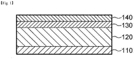
- FIG. 1 is a cross-sectional view of a negative electrode 100 according to an embodiment of the present invention, specifically showing a negative electrode structure before prelithiation.
- the negative electrode 100 includes a current collector 110; a negative electrode mixture layer 120 formed on the current collector 110; a lithium diffusion rate control layer 130 formed on the negative electrode mixture layer 120 by atomic layer deposition; and a lithium layer 140 formed on the lithium diffusion rate control layer 130.
- the negative electrode 100 of the present invention is provided with a lithium diffusion rate control layer 130 between the negative electrode mixture layer 120 and the lithium layer 140 to control (mitigate) the diffusion rate of lithium from the lithium layer and help the diffusion of lithium in a uniform distribution into the negative electrode mixture layer.
- the lithium diffusion rate control layer functions as a diffusion preventing layer for preventing lithium diffusion until the electrolyte injection and/or the initial charge and discharge time.
- the lithium diffusion rate control layer may function as an insulating layer between the negative electrode and the positive electrode when eluted and removed or remaining in the electrolyte.
- the lithium diffusion rate control layer 130 of the present invention is formed by atomic layer deposition to improve the problem of increasing the resistance of the lithium diffusion rate control layer by implementing a thin thickness of the nanometer level unit.
- a lithium diffusion rate control layer it is conventionally based on a simple application or coating of a polymer solution. In such a case, it is difficult to realize a thin film of several or tens of nanometers and the rate control layer may have a thickness of several to several hundred micrometers.
- the rate control layer has a thickness of several to several hundred micrometers, the resistance of the battery may increase.
- the rate control layer is formed by atomic layer deposition, a thin film of several to several tens of nanometers can be realized.
- the rate control layer may include a metal oxide or metalloid oxide material having insulating properties. Specifically, Al 2 O 3 , TiO 2 , ZrO 2 , HfO 2 , Ta 2 O 5 , Nb 2 O 5 , Y 2 O 3 , MbO, CeO 2 , SiO 2 , La 2 O 3 , Ln 2 O 3 , Lu 2 O 3 , PrAlO 3 , Er 2 O 3 , HfAlO, HfSiO, ZrSiO, ZrAlO, HfON, HfSiON, SrTiO 3 , BaTiO 3 , Barium strontium titanate oxide (BST) and one or two or more selected from the group consisting of laminates may be included.
- BST Barium strontium titanate oxide
- the lithium of the lithium layer is prevented from being diffused into the negative electrode mixture layer until the injection of the electrolyte or the initial charge and discharge.
- the remaining metal oxide layer protects the surface of the negative electrode, thereby improving the safety of the battery at high temperatures.
- Al 2 O 3 , TiO 2 , ZrO 2 , CeO 2 , Y 2 O 3 , SiO 2 may be said to be preferable as materials forming the rate control layer of the present invention, and the most preferred material is Al 2 O 3 .
- Al 2 O 3 is the most suitable material to be applied as a lithium diffusion rate control layer of the present invention since the precursor for the atomic layer deposition process is easy to obtain and the price is low, and the research on the atomic layer deposition method is most actively conducted.
- the lithium diffusion rate control layer since the lithium diffusion rate control layer needs to be compressed to allow the lithium layer and the negative electrode mixture layer to be energized under the activation pressure range applied during the first charge/discharge, the lithium diffusion rate control layer is formed by an atomic layer deposition method in order to realize a thin thickness of the lithium diffusion rate control layer,
- the lithium diffusion rate control layer may have a thickness of 0.1 to 100 nm, more preferably 0.5 to 50 nm.
- a thickness of the lithium diffusion rate control layer is too thin as less than 0.1 nm, an electric current may be applied before performing the prelithiation process after attaching the lithium thin film, thereby making it difficult to exert a function as a lithium diffusion rate preventing layer, resulting in uneven lithiation.
- the thickness of the lithium diffusion rate control layer is too thick as 100 nm or more, it may be difficult to smoothly diffuse lithium into the negative electrode due to the interruption of energization of the lithium layer and the negative electrode, and the resistance may increase.
- rate control layer having the above-mentioned characteristics, there is an effect of reducing the amount of lithium loss and the amount of lithium side reaction by reducing the diffusion of lithium before the electrolyte injection, and the increase in resistance can be minimized by allowing the rate control layer to have a thickness of tens of nanometers.
- the lithium diffusion rate control layer may be a single layer, but may have a two-layer structure of the first lithium diffusion rate control layer and the second lithium diffusion rate control layer, and if necessary, may have a multilayer structure of three or more layers.
- the materials of respective layers constituting the lithium diffusion rate control layer may be different kinds or may be a metal oxide of the same kind.
- the lithium layer is used as a source for lithiating the negative electrode active material included in the negative electrode mixture layer, and after a certain period of time from electrolyte injection, a certain amount of lithium layer participates in the prelithiation and moves into the negative electrode mixture layer. Even after prelithiation is completed to some extent, the residual amount may exist on the surface of the rate control layer.
- the lithium layer contains lithium metal.
- the lithium layer may be formed by electroplating, electrolytic plating, chemical vapor deposition, or may be laminated by binding a lithium metal thin film to the rate control layer by compression.
- the thickness of the lithium layer may be appropriately selected in consideration of the loading amount of the negative electrode, and specifically, has a thickness of 0.1 ⁇ m to 40 ⁇ m, preferably 1 ⁇ m to 20 ⁇ m.
- the thickness ratio of the lithium diffusion rate control layer and the lithium layer may be 1 : 100 to 1 : 20000. If the lithium diffusion rate control layer is too thick beyond the above ratio, lithiation may be insufficient and the irreversible capacity may increase. On the contrary, when the lithium diffusion rate control layer is too thin, it is energized after the lithium thin film is attached and before performing the prelithiation process, and thus it is difficult to function as a lithium diffusion rate preventing layer.
- the current collector is generally made of a thickness of 3 ⁇ m to 500 ⁇ m.
- the current collector is not particularly limited as long as it has high conductivity without causing a chemical change in the battery.
- the current collector may be made of a metal such as stainless steel, aluminum, nickel, titanium, sintered carbon, cooper, or aluminum or stainless steel of which the surface is treated with carbon, nickel, titanium, or silver, or the like.
- the negative electrode mixture layer includes a negative electrode active material, a binder, and a conductive material.
- the negative electrode according to the present invention may be prepared by applying a mixture of a negative electrode active material, a conductive material and a binder on the current collector and then drying them, and may further include a filler in the mixture, if necessary.
- the negative electrode active material includes a (semi) metal oxide
- the (semi) metal oxide may be in the form of particles or powder including the particles.
- the (semi) metal compound is at least one selected from the group consisting of Si, Sn, Al, Sb, Bi, As, Ge, Pb, Zn, Cd, In, TI, Ga and alloys thereof.
- the negative electrode active material may include one or a mixture of two or more compounds selected from the group consisting of SiO x (0 ⁇ x ⁇ 2), SnO and SnO 2 .
- the metal oxide may be provided with a shell portion containing a carbon material on at least part of the surface of the particle.
- the carbon material may be bonded, attached or coated on the surface of the (quasi) metal oxide particles.
- the carbon material may include at least one selected from the group consisting of crystalline carbon, natural graphite, artificial graphite, kish graphite, graphitized carbon fiber, graphitized mesocarbon microbeads, and amorphous carbon.
- the graphite may include those obtained by graphitizing one or more selected from the group consisting of soft carbon, hard carbon, pyrolytic carbon, mesophase pitch based carbon fiber, meso-carbon microbeads, mesophase pitches, petroleum or coal tar pitch derived cokes and activated carbon.
- the 50% particle size (D 50 ) of the metal oxide volume cumulative particle size distribution is 2 ⁇ m or more and 5 ⁇ m or less.
- the 90% particle size (D 90 ) of the volume cumulative particle size distribution of the particles is 25 ⁇ m or less, preferably 15 ⁇ m or less, and more preferably 10 ⁇ m or less.
- the maximum particle diameter of a volume cumulative particle size distribution is 35 micrometers or less, preferably 25 micrometers or less.
- the measurement of 50% particle size, 90% particle size and maximum particle size of the volume cumulative particle size distribution can be obtained by, for example, the cumulative frequency when measured using a laser diffraction particle size distribution measuring device manufactured by Nikkiso.
- the binder is added in an amount of 1 to 30% by weight, on the basis of the total weight of the electrode mixture, as a component that assists in bonding between the active material and the conductive material and bonding to the current collector.
- the high molecular weight polyacrylonitrile-acrylic acid copolymer may be used as such a binder, but is not limited thereto.
- polyvinylidene fluoride polyvinyl alcohol, carboxymethyl cellulose, starch, hydroxypropyl cellulose, recycled cellulose, polyvinylpyrrolidone, tetrafluoroethylene, polyethylene, polypropylene, ethylene-propylene-diene, sulfonated EDPM, styrene rubber, butylene rubber, fluorine rubber, etc. which are various copolymers.
- the conductive material is usually added in an amount of 1 to 30% by weight based on the total weight of the mixture including the negative electrode active material.
- a conductive material is not particularly limited as long as it has electrical conductivity without causing a chemical change in the battery, and examples thereof include graphite such as natural graphite and artificial graphite; carbon black such as carbon black, acetylene black, Ketjen black, channel black, furnace black, lamp black, and thermal black; conductive fibers such as carbon fiber and metal fiber; metal powders such as carbon fluoride, aluminum and nickel powder; conductive whiskey such as zinc oxide and potassium titanate; conductive metal oxides such as titanium oxide; and conductive materials such as polyphenylene derivatives and the like, but the present invention is not limited to these examples.
- the negative electrode may be prepared in the following order. First, a negative electrode mixture layer is formed on the surface of the current collector (S11). Next, a release plate is prepared and a lithium thin film is laminated on its surface to form a lithium thin film layer (S12). Subsequently, an atomic layer deposition process of introducing a metal oxide on the lithium thin film layer is repeated to form a lithium diffusion rate control layer (S13).
- the release plate may be used without limitation as long as the release plate can be easily removed from the laminate produced by sequentially stacking the lithium layer and the lithium diffusion rate control layer.
- the release plate may be a resin film layer made of polyethylene terephthalate.
- FIG. 2 is a schematic diagram illustrating the above-described negative electrode manufacturing method.
- a secondary battery may be manufactured by assembling an electrode assembly by interposing a separator in a space between the negative electrode and the positive electrode (S15) and injecting an electrolyte into the electrode assembly (S16).
- the negative electrode according to the present invention may be manufactured by a method of forming a lithium diffusion rate control layer on the negative electrode mixture layer and then forming a lithium layer on the surface of the control layer, without using a release plate.
- the method may include: forming a negative electrode mixture layer on the current collector (S21); repeating an atomic layer deposition process of introducing metal oxide on the negative electrode mixture layer to form a lithium diffusion rate control layer (S22); stacking a lithium thin film on the lithium diffusion rate control layer to manufacture a negative electrode (S23); preparing an electrode assembly including the negative electrode prepared in the step S23; and injecting an electrolyte into the electrode assembly (S25).
- the formation of the lithium layer and the formation of the lithium diffusion rate control layer may be understood by referring to the above-described method.
- FIG. 3 is a schematic diagram illustrating the above-described negative electrode manufacturing method.
- An atomic layer deposition is a self-controlled deposition process, and has been selected as a method of forming the rate control layer of the present invention because deposition can be performed by precisely controlling the thickness of the thin film.
- a lithium diffusion rate control layer was formed on the lithium thin film layer of the product of step S12 or the negative electrode mixture layer of the product of step S21 by using the polymer precursor as a raw material of the deposition process.
- the atomic layer deposition process includes: placing the result of the step S12 or the result of the step S21 in the chamber (S31); supplying metal atoms into the chamber; supplying a purge gas into the chamber; supplying an oxidant in the chamber to form a metal oxide layer; and supplying a purge gas into the chamber to remove unreacted oxidant.
- the temperature inside the chamber at 100 to 500°C. If the temperature of the chamber is less than 100°C, the reactivity of the reactant is not easy in a subsequent process, and if it exceeds 500°C, the crystallization of the metal oxide thin film is not performed, which is not preferable.
- the pressure inside the chamber is preferably adjusted to be 0.1 to 3.0 torr. If the pressure is less than 0.1 torr, the reactivity of the metal atoms supplied in the subsequent process is not easy, and if it exceeds 3.0 torr, it is not preferable because the process control is not easy.
- the (semi) metal or (semi) metal precursor is added as a reactant.
- the (semi) metal or (semi) metal precursor may contain one or more atoms 30 selected from the group consisting of Al, Ti, Zr, Hf, Ta, Nb, Y, Mb, Ce, Si, La, Ln, Lu, Pr, Er, Sr, Ba, and laminates.
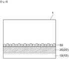
- the first portion 30' of the (quasi) metal atom is chemisorbed on the lithium thin film layer 20 or the negative electrode mixture layer 20' by providing a (semi) metal or (semi) metal precursor material to each lithium thin film layer 20 or the negative electrode mixture layer 20' of the result of the step S12 or the result of the step S21 located in the chamber like the above.
- the second portion 30" except for the first portion of the metal atom, is physically adsorbed to the first portion or drifted on the chamber.
- the next step is to provide a purge gas into the chamber.
- the purge gas may include an inert gas such as argon gas or nitrogen gas.
- the purge gas may be provided for about 1 to 50 seconds, more preferably 3 to 25 seconds, most preferably 5 to 10 seconds.
- the introduction of the purge gas and the vacuum purge may be performed together to remove the second part drifting in the chamber or physically adsorbed to the first part.
- the oxidant 40 is supplied into the chamber.
- the oxidant one selected from the group consisting of O 3 , O 2 , H 2 0, plasma O 2 , and remote plasma O 2 may be used alone, or two or more may be mixed and used in some cases.
- the oxidant for about 0.5 to 10 seconds into the chamber.
- the oxidant chemically reacts with the precursor molecules 30a which are the first portions of the reaction material chemisorbed on the negative electrode mixture layer or the lithium thin film layer to thereby oxidize the precursor molecules.
- a purge gas of the same kind as described above is supplied to remove the oxidant which has not reacted with the first portion of the metal atom.
- the type and introduction time of the purge gas are the same as described above.
- an oxidant that is not chemically reacted with the metal atoms is removed from the chamber as shown in FIG. 8 . Accordingly, the metal oxide layer 50 is formed on the lithium thin film layer or the negative electrode mixture layer.
- the above steps may be repeated at least once or more.
- the thickness of the metal oxide layer on the lithium thin film layer or the negative electrode mixture layer is adjusted according to the number of repetitions of the processes.
- the purge gas and the oxidant may be supplied together to form the metal oxide layer.
- the (pre) lithiation of the negative electrode proceeds during electrolyte injection and/or initial charge/discharge step after fabrication of the battery, and at least a part of the negative electrode active material included in the negative electrode mixture layer is lithiated.
- the battery includes an electrode assembly consisting of a negative electrode, a positive electrode, and a separator interposed between the negative electrode and the positive electrode, and the electrode assembly is inserted into a suitable exterior material and the electrolyte may be injected and sealed.
- lithiation may proceed by injecting the electrolyte.
- the electrode assembly including components such as an electrode is impregnated in the electrolyte.
- the lithium diffusion rate control layer of the present invention is eluted and removed, lithium of the lithium layer may be diffused into the negative electrode mixture layer.
- the battery is activated by first applying a current to perform initial charge/discharge (formation).
- the activation process may be performed while a predetermined pressure is applied to the battery.
- a material which may be compressed under a predetermined pressure and energized, as a control layer, lithium may be diffused into the negative electrode mixture layer through an activation process under a predetermined pressure.
- the negative electrode active material included in the negative electrode mixture layer in particular, the (quasi) metal oxide and lithium described above may be combined to form an alloy.
- a part of lithium may be inserted into the crystal structure of the negative electrode active material.
- the lithium ion can be well delivered to the inside of the negative electrode through the electrolyte in the process of prelithiation, and thus there is an advantage that uniform prelithiation can be performed over the entire body of the negative electrode.
- the rate control layer is interposed between the negative electrode mixture layer and the lithium layer, diffusion of lithium is prevented by the control layer in the state before the injection of the electrolyte, and almost no lithiation proceeds. Almost all prelithiation can be performed after the injection of the electrolyte into the electrode assembly and/or at the first charge and discharge step.
- the first charge and discharge is preferably carried out in a state in which a predetermined pressure is applied to the battery in order to energize the control layer and the negative electrode. Thereafter, as long as lithium metal remains in the lithium layer, the prelithiation may be continuously performed and may be affected, for example, may be accelerated by the charge/discharge of the battery.
- the present invention provides a lithium secondary battery including a negative electrode, a positive electrode, a separator interposed between the negative electrode and the positive electrode, and an electrolyte, and the negative electrode has the above-described configuration features.
- the positive electrode is prepared by applying a mixture of a positive electrode active material, a conductive material and a binder on a positive electrode current collector, followed by drying. If necessary, a filler may be further added to the mixture.
- the conductive material, the current collector, and the binder may be understood by referring to the above description about the negative electrode.
- the separator may be formed of an insulating thin film having high ion permeability and mechanical strength.
- the process diameter of the separator is generally between 0.01 and 10 ⁇ m, the thickness may be between 5 and 300 ⁇ m.
- Examples of such a separator include olefin-based polymers such as polypropylene which is chemically resistant and hydrophobic; a sheet or a nonwoven fabric made of glass fiber, polyethylene or the like.
- a solid electrolyte such as a polymer is used as the electrolyte, the solid electrolyte may also serve as a separator.
- the electrolyte solution contains an organic solvent and a predetermined amount of lithium salt
- examples of components of the organic solvent may include aprotic organic solvents such as N-methyl-2-pyrrolidinone, propylene carbonate, ethylene carbonate, butylene carbonate, dimethyl carbonate, diethyl carbonate, gamma-butylo lactone, 1,2-dimethoxy ethane, tetrahydroxy franc, 2-methyl tetrahydrofuran, dimethyl sulfoxide, 1,3-dioxolon, formamide, dimethylformamide, dioxorone, acetonitrile, nitromethane, methyl formate, methyl acetate, phosphate triester, trimethoxy methane, dioxon derivatives, sulfolane, methyl sulfolane, 1,3-dimethyl-2-imidazolidinone, propylene carbonate derivatives, tetrahydrofuran derivatives
- the lithium salt is a substance that is soluble in the electrolyte.
- the examples of the lithium salt include LiCl, LiBr, LiI, LiClO 4 , LiBF 4 , LiB 10 Cl 10 , LiPF 6 , LiCF 3 SO 3 , LiCF 3 CO 2 , LiAsF 6 , LiSbF 6 , LiAlCl 4 , CH 3 SO 3 Li, CF 3 SO 3 Li, (CF 3 SO 2 ) 2 NLi, chloroborane lithium, lower aliphatic carboxylic acid lithium, lithium 4-phenylborate, imide and the like.
- the secondary battery of the present invention may be manufactured by accommodating/sealing the electrode assembly, in which the positive electrode and the negative electrode are alternately stacked with a separator, in an exterior material such as a battery case together with the electrolyte.
- the manufacturing method of a secondary battery can use a conventional method without limitation.
- a battery module including the secondary battery as a unit cell and a battery pack including the same. Since the battery module and the battery pack include a secondary battery exhibiting excellent fast charging characteristics in high loading, the battery module and the battery pack may be used as a power source for an electric vehicle, a hybrid electric vehicle, a plug-in hybrid electric vehicle, and a power storage system.
- battery elements for example, conductive materials, which are not described in detail herein, reference may be made to elements commonly used in the battery field, particularly in the lithium secondary battery field.
- SiO (D50: 3.2 ⁇ m) and artificial graphite were mixed at a weight ratio of 3 : 7 to be used as a negative electrode active material.
- the negative electrode active material, SBR binder, CMC and acetylene black were added to water in a weight ratio of 93 : 3 : 1.5 : 2.5 to prepare a negative electrode mixture.
- the mixture was uniformly coated on 10 ⁇ m copper foil, the drying temperature was 90°C, and the coating rate was 0.2 m/min.
- the coated negative electrode was rolled to match the porosity of 30% to meet the target thickness. Then, it was dried for 12 hours in a 180 °C vacuum oven.
- the negative electrode of the above preparation example was placed in a chamber (150°C, 0.1 torr), and trimethylaluminum and H 2 O gas were injected with a pressure of 1 torr nitrogen gas at a ratio of 17 : 1.
- the atomic layer deposition process was repeatedly performed until the thickness of the Al 2 O 3 layer became about 3 nm on the negative electrode mixture layer by the following reactions (A) and (B).
- a negative electrode was prepared by laminating a lithium thin film having a thickness of 10 ⁇ m.
- Coin cells were prepared in the order of negative electrode/separator (porous film made of polypropylene (20 ⁇ m, Celgard))/lithium foil by using lithium foil and stainless steel upper and lower plates as counter electrodes of the obtained negative electrode and prepared negative electrode.
- the electrolyte was injected immediately after assembling the coin cell. At this time, the electrolyte is a mixture of ethylene carbonate and ethyl methyl carbonate in a mass ratio of 3 : 7.
- a battery was manufactured in the same manner as in Example 1, except that the injection time of the electrolyte was changed to a time after 2 hours from the assembly of the coin cell.
- a battery was manufactured in the same manner as in Example 1, except that an atomic layer deposition process for forming an Al 2 O 3 layer on the negative electrode mixture layer was omitted in Example 1.
- a battery was manufactured in the same manner as in Comparative Example 1, except that the injection time of the electrolyte was changed to a time after 2 hours from the assembly of the coin cell.
- LiCoO 2 SBR binder, CMC and acetylene black as the positive electrode active material were added to water in a weight ratio of 93 : 3 : 1.5 : 2.5 to prepare a positive electrode mixture.
- the mixture was uniformly coated on 10 ⁇ m aluminum foil and dried for 12 hours in a 50°C vacuum oven to prepare a positive electrode.
- 1-stack mono cells were prepared in the order of a negative electrode/separator (polypropylene material porous film; 20 ⁇ m, Celgard)/positive electrode, using a positive electrode and a negative electrode having a lithium diffusion rate control layer and a lithium layer prepared in Example 1.
- the electrolyte was injected after 2 hours from the assembly of the mono cells At this time, the electrolyte is a mixture of ethylene carbonate and ethyl methyl carbonate in a mass ratio of 3 : 7.
- 1-stack mono cells were prepared in the order of negative electrode/separator (porous film made of polypropylene (20 ⁇ m, Celgard))/positive electrode.
- the electrolyte was injected after 2 hours from the assembly of the mono cells At this time, the electrolyte is a mixture of ethylene carbonate and ethyl methyl carbonate in a mass ratio of 3 : 7.
- a polymethyl methacrylate solution (0.5wt% PMMA (Mw: 890k) in anisole solution) on a negative electrode mixture layer was coated by a solution casting method and dried for 24 hours at 80°C to form a lithium diffusion rate control layer. Thereafter, a negative electrode was prepared in the same manner as in Example 1.
- the thickness of the polymethyl methacrylate layer is 200 nm.
- 1-stack mono cells were prepared in the order of negative electrode/separator (porous film made of polypropylene (20 ⁇ m, Celgard))/positive electrode.
- the electrolyte was injected after 2 hours from the assembly of the mono cells At this time, the electrolyte is a mixture of ethylene carbonate and ethyl methyl carbonate in a mass ratio of 3 : 7.
- the first discharge was first performed at 0.1 C, up to 1.5 V in CC mode, followed by charging at 0.1 C, 5 mV, and 0.005 C cut conditions in CC/CV mode, and discharging at 0.1 C, up to 1.5 V in CC mode, to thereby perform the irreversible capacity at the first charge and discharge.
- Total dosage is the sum of Li intercalation capacity and SEI production capacity.
- the Li intercalation capacity can be obtained by measuring the first capacity up to 1.5V discharge to obtain the capacity of lithium inserted into the negative electrode.
- the SEI generation capacity would also limit the 1 st irreversible capacity of the lithiated negative electrode from the 1 st irreversible capacity of the negative electrode prior to lithiation.
- Example 1 and Comparative Example 1 in which the electrolyte was injected immediately after fabrication of the coin cell were found to have similar amounts of lithiation.
- Comparative Examples 2 and 3 which did not include the lithium diffusion rate control layer had a significantly low amount lithiation compared to that of Examples 2 and 3 and Comparative Example 4 which included a lithium diffusion rate control layer. Accordingly, it was found that the loss of lithium was less before lithiation in the negative electrode having the lithium diffusion rate control layer of the present invention.
- Example 3 Since the comparative example 3 does not have a lithium diffusion rate control layer, its resistance value is low, compared with that of the comparative example 4 provided with a lithium diffusion rate control layer.
- Example 3 has a lithium diffusion rate control layer as in Comparative Example 4, but because the lithium diffusion rate control layer is much thinner than that of Comparative Example 4, it can be seen that the resistance is low, which is equivalent to or lower than that of the comparative example 3 which is not equipped with a lithium diffusion rate control layer. Accordingly, it was found that the negative electrode with the lithium diffusion rate control layer of the present invention did not show an increase in the resistance.
Landscapes
- Chemical & Material Sciences (AREA)
- Chemical Kinetics & Catalysis (AREA)
- General Chemical & Material Sciences (AREA)
- Engineering & Computer Science (AREA)
- Electrochemistry (AREA)
- Materials Engineering (AREA)
- Manufacturing & Machinery (AREA)
- Mechanical Engineering (AREA)
- Metallurgy (AREA)
- Organic Chemistry (AREA)
- Inorganic Chemistry (AREA)
- Composite Materials (AREA)
- Secondary Cells (AREA)
- Battery Electrode And Active Subsutance (AREA)
Abstract
Description
- This application claims the benefit of priority based on Korean Patent Application No.
10-2018-0132011, filed on October 31, 2018 - As the price of energy sources increases due to depletion of fossil fuels and the interest in environmental pollution increases, the demand for environmentally friendly alternative energy sources becomes an indispensable factor for future life. Especially, as technology development and demand for mobile devices are increasing, demand for secondary batteries as energy sources is rapidly increasing.
- Typically, in terms of the shape of the battery, there is a high demand for a prismatic secondary battery and a pouch-type secondary battery that can be applied to products such as mobile phones with a small thickness. In terms of materials, there is a high demand for lithium secondary batteries such as lithium ion batteries and lithium ion polymer batteries having high energy density, discharge voltage, and output stability.
- Generally, in order to prepare a secondary battery, first, a positive electrode and a negative electrode are formed by applying an electrode mixture containing an electrode active material to a surface of a current collector, then a separate is interposed therebetween to thereby make an electrode assembly, which is then mounted in a cylindrical or rectangular metal can or inside a pouch-type case of an aluminum laminate sheet, and a liquid electrolyte is injected or impregnated into the electrode assembly or a solid electrolyte is used to prepare a secondary battery.
- In general, the negative electrode of a lithium secondary battery uses a carbon material such as graphite, but the theoretical capacity density of carbon is 372 mAh/g (833 mAh/cm3). Therefore, in order to improve the energy density of the negative electrode, silicon (Si), tin (Sn), oxides and alloys thereof which are alloyed with lithium are considered as negative electrode materials. Among them, silicon-based materials have attracted attention due to their low cost and high capacity (4200 mAh/g).
- In the carbon-based negative electrode active material, a solid electrolyte interface (SEI) layer is formed on the surface of the negative electrode active material during an initial charge/discharge process (activation process). As a result, an initial irreversible phenomenon is caused and the electrolyte capacity is depleted in the course of continuous charge/discharge, thereby reducing the battery capacity.
- In addition, although the silicon-based material shows a high capacity, a problem arises in that the initial irreversible capacity is large. During charging and discharging of the lithium secondary battery, lithium discharged from the positive electrode is inserted into the negative electrode at the time of charging, and is discharged from the negative electrode at the time of discharging and returns to the positive electrode. In the case of the silicon negative electrode active material, a large amount of lithium inserted into the negative electrode does not return to the positive electrode at the time of initial charging and thus the initial irreversible capacity becomes large. When the initial irreversible capacity increases, there occurs a problem that the battery capacity and the cycle are rapidly reduced.
- As one of methods for solving the problems related to the initial irreversibility, prelithiation technologies for pre-inserting lithium into the negative electrode have been attempted. Among them, the lithium direct contact method is a method of directly laminating thin film lithium on the negative electrode layer, and after the cell assembly, the electrolyte is injected to move the lithium of the lithium layer to the negative electrode (diffusion) to increase the lithium content in the negative electrode, to thereby solve the problem of irreversible capacity reduction.
- However, in the manufacture of a lithium secondary battery, it often happens that time is delayed when electrolyte is injected or until initial charge and discharge after cell assembly. Herein, before the injection of the electrolyte, lithium of the lithium layer attached to the negative electrode may be unevenly moved into the electrode (solid-diffusion), thereby increasing resistance, or lithium may be diffused into the air, causing a problem of loss of lithium amount.
- On the other hand, Korean Patent Publication No.
10-2018-0057513 - An object of the present invention is to provide a novel (pre) lithiation method for a negative electrode for a lithium ion battery, a negative electrode prepared by the method and a lithium ion secondary battery including the negative electrode.
- In addition, another object of the present invention is to minimize the amount of the lithium loss and to reduce the amount of lithium side reactions by relieving the solid-diffusion rate of lithium generated as the time until electrolyte injection is delayed after cell assembly.
- In addition, another object of the present invention is to provide a method for (pre) lithiation of a negative electrode for a secondary battery having improved battery performance by improving a problem of a resistance increase of a lithium diffusion rate control layer.
- In order to solve the above problems, a negative electrode for a lithium secondary battery of the present invention includes a current collector; a negative electrode mixture layer formed on the current collector; a lithium diffusion rate control layer formed on the negative electrode mixture layer by atomic layer deposition; and a lithium layer formed on the lithium diffusion rate control layer.
- In an example of the present invention, the lithium diffusion rate control layer may control diffusion of lithium from the lithium layer to the negative electrode mixture layer until injection of an electrolyte.
- In an example of the present invention, the lithium diffusion rate control layer may control diffusion of lithium from the lithium layer to the negative electrode mixture layer until a first charge/discharge.
- In an example of the present invention, a thickness of the lithium diffusion rate control layer may be 0.1 to 100 nm and preferably 0.5 to 50 nm.
- In an example of the present invention, the negative electrode mixture layer may include one compound or a mixture of two or more selected from the group consisting of SiOx (0 <x ≤ 2), SnO and SnO2.
- In an example of the present invention, the lithium diffusion rate control layer may include one or two or more selected from the group consisting of Al2O3, TiO2, ZrO2, HfO2, Ta2O5, Nb2O5, Y2O3, MbO, CeO2, SiO2, La2O3, Ln2O3, Lu2O3, PrAlO3, Er2O3, HfAlO, HfSiO, ZrSiO, ZrAlO, HfON, HfSiON, SrTiO3, BaTiO3, BST and laminates and may more preferably be Al2O3.
- In an example of the present invention, a thickness ratio of the lithium diffusion rate control layer and the lithium layer may be 1 : 100 to 1 : 20000.
- A method for manufacturing a lithium secondary battery of the present invention includes: a step of forming a negative electrode mixture layer on a current collector (S11); a step of forming a lithium thin film layer on a surface of a release plate (S12); a step of forming a lithium diffusion rate control layer by repeating an atomic layer deposition process of introducing a metal oxide on the lithium thin film layer (S13); a step of preparing a negative electrode by stacking products of step S11 and step S13 so that the negative electrode mixture layer and the lithium diffusion rate control layer may face each other (S14); a step of manufacturing an electrode assembly including the negative electrode prepared in the step S14 (S15); and a step of injecting an electrolyte into the electrode assembly (S16).
- A method for manufacturing a lithium secondary battery according to an example of the present invention includes: a step of forming a negative electrode mixture layer on a current collector (S21); a step of forming a lithium diffusion rate control layer by repeating an atomic layer deposition process of introducing a metal oxide on the negative electrode mixture layer (S22); a step of manufacturing a negative electrode by laminating a lithium thin film on the lithium diffusion rate control layer (S23); a step of manufacturing an electrode assembly including the negative electrode prepared in the step S23 (S24); and a step of injecting an electrolyte into the electrode assembly (S25).
- Herein, the lithium diffusion rate control layer may control diffusion of lithium from the lithium layer to the negative electrode mixture layer until injection of an electrolyte.
- According to an example of the present invention, a thickness of the lithium diffusion rate control layer may be 0.1 to 100 nm and preferably 0.5 to 50 nm.
- According to an example of the present invention, the atomic layer deposition process of the step S13 or the step S22 may include: a step of positioning a product the step S12 or the S21 in a chamber; a step of supplying metal atoms into the chamber; a step of supplying a purge gas into the chamber; a step of supplying an oxidant into the chamber to form a metal oxide layer; and a step of supplying the purge gas into the chamber to remove an unreacted oxidant.
- Since the negative electrode according to the present invention includes a lithium diffusion rate control layer between the lithium thin film and the negative electrode mixture layer, the rate of diffusion of lithium may be controlled in the prelithiation process, and cycle characteristics may be improved by suppressing loss of lithium or side reaction of lithium.
- In addition, the manufacturing method of the lithium ion secondary battery according to the present invention has an advantage of minimizing the increase in resistance due to the material properties of the lithium diffusion rate control layer by forming a very thin lithium diffusion rate control layer by an atomic layer deposition method.
-
-
FIG. 1 is a schematic view showing the structure of a negative electrode according to an embodiment of the present invention. -
FIGS. 2 and3 schematically show a method of manufacturing a negative electrode according to an embodiment of the present invention. -
FIGS. 4 to 8 are schematic views showing an atomic layer deposition process for forming a lithium diffusion rate control layer of the present invention. - The terms and words used in the present specification and claims should not be construed as limited to ordinary or dictionary terms and the inventor may properly define the concept of the terms in order to best describe its invention. The terms and words should be construed as meaning and concept consistent with the technical idea of the present invention. Accordingly, the embodiments described in the specification and the configurations described in the drawings are only the most preferred embodiments of the present invention, and do not represent all of the technical ideas of the present invention. It is to be understood that there may be various equivalents and variations in place of them at the time of filing the present application.
- In the present specification, when a part is "connected" to another part, this includes not only "directly connected" but also "electrically connected" between the parts while having another element therebewteen.
- Also, throughout the specification, when an element is referred to as "including" an element, it is understood that the element may include other elements as well unless specifically stated otherwise.
- As used throughout this specification, the terms "about", "substantially", and the like, are used to mean a value or something like this when unique manufacturing and material tolerances are presented, and the terms are used to prevent unscrupulous infringers from unfair use of the disclosure including accurate or absolute figures in order to aid in the understanding of the present disclosure.
- Throughout this specification, the term "combination(s) thereof' included in the expression of the Markush form means one or more mixtures or combinations selected from the group consisting of the elements described in the Markush form representation, and it means to include one or more selected from the group consisting of the above components.
- The present invention relates to a negative electrode for an electrochemical device and an electrochemical device having the same. In the present invention, the electrochemical device includes all devices that undergo an electrochemical reaction, and specific examples thereof include all kinds of primary and secondary cells, fuel cells, solar cells, or capacitors. In particular, a lithium secondary battery such as a lithium metal secondary battery, a lithium ion secondary battery, a lithium polymer secondary battery or a lithium ion polymer secondary battery is preferable among the secondary batteries .
- Throughout this specification, the expression "A and/or B" means "A or B or both."
- Hereinafter, the present invention will be described in detail.
- As a negative electrode active material, a material of silicon or carbon material inevitably causes a decrease in battery capacity due to high initial irreversible characteristics. As one of the methods to solve this problem, a prelithiation technology for pre-inserting lithium into a negative electrode has been attempted. Among them, the lithium direct contact method is a method of directly laminating thin film lithium on the negative electrode layer, and after the cell assembly, the electrolyte is injected to move the lithium of the lithium layer to the negative electrode (diffusion) to increase the lithium content in the negative electrode, to thereby solve the problem of irreversible capacity reduction.
- However, in the manufacture of a lithium secondary ion battery, it often happens that time is delayed when electrolyte is injected after cell assembly. Herein, before the injection of the electrolyte, lithium of the lithium layer attached to the negative electrode may be unevenly moved into the electrode (solid-diffusion), thereby increasing resistance, or lithium may be diffused into the air, causing a problem of loss of lithium amount.
- Accordingly, the present invention discloses a new electrode structure and a lithium secondary battery having the same by interposing a lithium diffusion rate control layer between a negative electrode mixture layer and a lithium layer to solve the above problems.
-
FIG. 1 is a cross-sectional view of a negative electrode 100 according to an embodiment of the present invention, specifically showing a negative electrode structure before prelithiation. Referring toFIG. 1 , the negative electrode 100 includes acurrent collector 110; a negativeelectrode mixture layer 120 formed on thecurrent collector 110; a lithium diffusionrate control layer 130 formed on the negativeelectrode mixture layer 120 by atomic layer deposition; and alithium layer 140 formed on the lithium diffusionrate control layer 130. - The negative electrode 100 of the present invention is provided with a lithium diffusion
rate control layer 130 between the negativeelectrode mixture layer 120 and thelithium layer 140 to control (mitigate) the diffusion rate of lithium from the lithium layer and help the diffusion of lithium in a uniform distribution into the negative electrode mixture layer. - As described later, in the present invention, prelithiation is performed during electrolyte injection and/or initial charge and discharge. Accordingly, the lithium diffusion rate control layer functions as a diffusion preventing layer for preventing lithium diffusion until the electrolyte injection and/or the initial charge and discharge time. On the other hand, after performing the prelithiation process, the lithium diffusion rate control layer may function as an insulating layer between the negative electrode and the positive electrode when eluted and removed or remaining in the electrolyte.
- Furthermore, the lithium diffusion
rate control layer 130 of the present invention is formed by atomic layer deposition to improve the problem of increasing the resistance of the lithium diffusion rate control layer by implementing a thin thickness of the nanometer level unit. In forming a lithium diffusion rate control layer, it is conventionally based on a simple application or coating of a polymer solution. In such a case, it is difficult to realize a thin film of several or tens of nanometers and the rate control layer may have a thickness of several to several hundred micrometers. Herein, if the rate control layer has a thickness of several to several hundred micrometers, the resistance of the battery may increase. However, in the present invention, since the rate control layer is formed by atomic layer deposition, a thin film of several to several tens of nanometers can be realized. - Hereinafter, the lithium diffusion rate control layer will be described in more detail.
- According to one specific embodiment of the present invention, the rate control layer may include a metal oxide or metalloid oxide material having insulating properties. Specifically, Al2O3, TiO2, ZrO2, HfO2, Ta2O5, Nb2O5, Y2O3, MbO, CeO2, SiO2, La2O3, Ln2O3, Lu2O3, PrAlO3, Er2O3, HfAlO, HfSiO, ZrSiO, ZrAlO, HfON, HfSiON, SrTiO3, BaTiO3, Barium strontium titanate oxide (BST) and one or two or more selected from the group consisting of laminates may be included.
- By interposing the (quasi) metal oxide having insulating properties between the negative electrode mixture layer and the lithium layer, the lithium of the lithium layer is prevented from being diffused into the negative electrode mixture layer until the injection of the electrolyte or the initial charge and discharge. On the other hand, after the prelithiation, the remaining metal oxide layer protects the surface of the negative electrode, thereby improving the safety of the battery at high temperatures. In this respect, Al2O3, TiO2, ZrO2, CeO2, Y2O3, SiO2 may be said to be preferable as materials forming the rate control layer of the present invention, and the most preferred material is Al2O3. Al2O3 is the most suitable material to be applied as a lithium diffusion rate control layer of the present invention since the precursor for the atomic layer deposition process is easy to obtain and the price is low, and the research on the atomic layer deposition method is most actively conducted.
- In the present invention, since the lithium diffusion rate control layer needs to be compressed to allow the lithium layer and the negative electrode mixture layer to be energized under the activation pressure range applied during the first charge/discharge, the lithium diffusion rate control layer is formed by an atomic layer deposition method in order to realize a thin thickness of the lithium diffusion rate control layer,
- The lithium diffusion rate control layer may have a thickness of 0.1 to 100 nm, more preferably 0.5 to 50 nm. When the thickness of the lithium diffusion rate control layer is too thin as less than 0.1 nm, an electric current may be applied before performing the prelithiation process after attaching the lithium thin film, thereby making it difficult to exert a function as a lithium diffusion rate preventing layer, resulting in uneven lithiation. On the contrary, when the thickness of the lithium diffusion rate control layer is too thick as 100 nm or more, it may be difficult to smoothly diffuse lithium into the negative electrode due to the interruption of energization of the lithium layer and the negative electrode, and the resistance may increase.
- By providing a rate control layer having the above-mentioned characteristics, there is an effect of reducing the amount of lithium loss and the amount of lithium side reaction by reducing the diffusion of lithium before the electrolyte injection, and the increase in resistance can be minimized by allowing the rate control layer to have a thickness of tens of nanometers.
- The lithium diffusion rate control layer may be a single layer, but may have a two-layer structure of the first lithium diffusion rate control layer and the second lithium diffusion rate control layer, and if necessary, may have a multilayer structure of three or more layers. At this time, the materials of respective layers constituting the lithium diffusion rate control layer may be different kinds or may be a metal oxide of the same kind.
- Hereinafter, the lithium layer will be described in detail.
- The lithium layer is used as a source for lithiating the negative electrode active material included in the negative electrode mixture layer, and after a certain period of time from electrolyte injection, a certain amount of lithium layer participates in the prelithiation and moves into the negative electrode mixture layer. Even after prelithiation is completed to some extent, the residual amount may exist on the surface of the rate control layer.
- The lithium layer contains lithium metal. In one specific embodiment of the present invention, the lithium layer may be formed by electroplating, electrolytic plating, chemical vapor deposition, or may be laminated by binding a lithium metal thin film to the rate control layer by compression.
- The thickness of the lithium layer may be appropriately selected in consideration of the loading amount of the negative electrode, and specifically, has a thickness of 0.1 µm to 40 µm, preferably 1 µm to 20 µm.
- The thickness ratio of the lithium diffusion rate control layer and the lithium layer may be 1 : 100 to 1 : 20000. If the lithium diffusion rate control layer is too thick beyond the above ratio, lithiation may be insufficient and the irreversible capacity may increase. On the contrary, when the lithium diffusion rate control layer is too thin, it is energized after the lithium thin film is attached and before performing the prelithiation process, and thus it is difficult to function as a lithium diffusion rate preventing layer.
- Hereinafter, the current collector and the negative electrode mixture layer constituting the negative electrode of the present invention will be described in detail.
- The current collector is generally made of a thickness of 3 µm to 500 µm. The current collector is not particularly limited as long as it has high conductivity without causing a chemical change in the battery. For example, the current collector may be made of a metal such as stainless steel, aluminum, nickel, titanium, sintered carbon, cooper, or aluminum or stainless steel of which the surface is treated with carbon, nickel, titanium, or silver, or the like.
- The negative electrode mixture layer includes a negative electrode active material, a binder, and a conductive material. The negative electrode according to the present invention may be prepared by applying a mixture of a negative electrode active material, a conductive material and a binder on the current collector and then drying them, and may further include a filler in the mixture, if necessary.
- In one specific embodiment of the present invention, the negative electrode active material includes a (semi) metal oxide, and the (semi) metal oxide may be in the form of particles or powder including the particles.
- The (semi) metal compound is at least one selected from the group consisting of Si, Sn, Al, Sb, Bi, As, Ge, Pb, Zn, Cd, In, TI, Ga and alloys thereof. Preferably, the negative electrode active material may include one or a mixture of two or more compounds selected from the group consisting of SiOx (0<x≤ 2), SnO and SnO2.
- On the other hand, in one specific embodiment of the present invention, the metal oxide may be provided with a shell portion containing a carbon material on at least part of the surface of the particle. The carbon material may be bonded, attached or coated on the surface of the (quasi) metal oxide particles. The carbon material may include at least one selected from the group consisting of crystalline carbon, natural graphite, artificial graphite, kish graphite, graphitized carbon fiber, graphitized mesocarbon microbeads, and amorphous carbon. In addition, the graphite may include those obtained by graphitizing one or more selected from the group consisting of soft carbon, hard carbon, pyrolytic carbon, mesophase pitch based carbon fiber, meso-carbon microbeads, mesophase pitches, petroleum or coal tar pitch derived cokes and activated carbon.
- According to a preferred embodiment of the present invention, the 50% particle size (D50) of the metal oxide volume cumulative particle size distribution is 2 µm or more and 5 µm or less. The 90% particle size (D90) of the volume cumulative particle size distribution of the particles is 25 µm or less, preferably 15 µm or less, and more preferably 10 µm or less. Moreover, the maximum particle diameter of a volume cumulative particle size distribution is 35 micrometers or less, preferably 25 micrometers or less. The measurement of 50% particle size, 90% particle size and maximum particle size of the volume cumulative particle size distribution can be obtained by, for example, the cumulative frequency when measured using a laser diffraction particle size distribution measuring device manufactured by Nikkiso.
- The binder is added in an amount of 1 to 30% by weight, on the basis of the total weight of the electrode mixture, as a component that assists in bonding between the active material and the conductive material and bonding to the current collector. The high molecular weight polyacrylonitrile-acrylic acid copolymer may be used as such a binder, but is not limited thereto. Other examples include polyvinylidene fluoride, polyvinyl alcohol, carboxymethyl cellulose, starch, hydroxypropyl cellulose, recycled cellulose, polyvinylpyrrolidone, tetrafluoroethylene, polyethylene, polypropylene, ethylene-propylene-diene, sulfonated EDPM, styrene rubber, butylene rubber, fluorine rubber, etc. which are various copolymers.
- The conductive material is usually added in an amount of 1 to 30% by weight based on the total weight of the mixture including the negative electrode active material. Such a conductive material is not particularly limited as long as it has electrical conductivity without causing a chemical change in the battery, and examples thereof include graphite such as natural graphite and artificial graphite; carbon black such as carbon black, acetylene black, Ketjen black, channel black, furnace black, lamp black, and thermal black; conductive fibers such as carbon fiber and metal fiber; metal powders such as carbon fluoride, aluminum and nickel powder; conductive whiskey such as zinc oxide and potassium titanate; conductive metal oxides such as titanium oxide; and conductive materials such as polyphenylene derivatives and the like, but the present invention is not limited to these examples.
- In the present invention, the negative electrode may be prepared in the following order. First, a negative electrode mixture layer is formed on the surface of the current collector (S11). Next, a release plate is prepared and a lithium thin film is laminated on its surface to form a lithium thin film layer (S12). Subsequently, an atomic layer deposition process of introducing a metal oxide on the lithium thin film layer is repeated to form a lithium diffusion rate control layer (S13). In the present invention, the release plate may be used without limitation as long as the release plate can be easily removed from the laminate produced by sequentially stacking the lithium layer and the lithium diffusion rate control layer. For example, the release plate may be a resin film layer made of polyethylene terephthalate. Next, a negative electrode is manufactured by stacking the products of step S11 and step S13 so that the negative electrode mixture layer and the lithium diffusion rate control layer may face each other (S14).
FIG. 2 is a schematic diagram illustrating the above-described negative electrode manufacturing method. Subsequently, a secondary battery may be manufactured by assembling an electrode assembly by interposing a separator in a space between the negative electrode and the positive electrode (S15) and injecting an electrolyte into the electrode assembly (S16). - Alternatively, the negative electrode according to the present invention may be manufactured by a method of forming a lithium diffusion rate control layer on the negative electrode mixture layer and then forming a lithium layer on the surface of the control layer, without using a release plate. Specifically, the method may include: forming a negative electrode mixture layer on the current collector (S21); repeating an atomic layer deposition process of introducing metal oxide on the negative electrode mixture layer to form a lithium diffusion rate control layer (S22); stacking a lithium thin film on the lithium diffusion rate control layer to manufacture a negative electrode (S23); preparing an electrode assembly including the negative electrode prepared in the step S23; and injecting an electrolyte into the electrode assembly (S25). Here, the formation of the lithium layer and the formation of the lithium diffusion rate control layer may be understood by referring to the above-described method.
FIG. 3 is a schematic diagram illustrating the above-described negative electrode manufacturing method. - Hereinafter, the atomic layer deposition process of the present invention will be described in detail.
- An atomic layer deposition (ALD) is a self-controlled deposition process, and has been selected as a method of forming the rate control layer of the present invention because deposition can be performed by precisely controlling the thickness of the thin film.
- In the present invention, a lithium diffusion rate control layer was formed on the lithium thin film layer of the product of step S12 or the negative electrode mixture layer of the product of step S21 by using the polymer precursor as a raw material of the deposition process.
- The atomic layer deposition process includes: placing the result of the step S12 or the result of the step S21 in the chamber (S31); supplying metal atoms into the chamber; supplying a purge gas into the chamber; supplying an oxidant in the chamber to form a metal oxide layer; and supplying a purge gas into the chamber to remove unreacted oxidant.
- When placing the resultant of the step S12 or the resultant of the step S21 in the chamber, it is preferable to maintain the temperature inside the chamber at 100 to 500°C. If the temperature of the chamber is less than 100°C, the reactivity of the reactant is not easy in a subsequent process, and if it exceeds 500°C, the crystallization of the metal oxide thin film is not performed, which is not preferable.
- In addition, the pressure inside the chamber is preferably adjusted to be 0.1 to 3.0 torr. If the pressure is less than 0.1 torr, the reactivity of the metal atoms supplied in the subsequent process is not easy, and if it exceeds 3.0 torr, it is not preferable because the process control is not easy.
- Referring to
FIG. 4 , after placing the resultant of the step S12 or the resultant of the step S21 in thechamber 1 that satisfies the above temperature and pressure conditions, the (semi) metal or (semi) metal precursor is added as a reactant. The (semi) metal or (semi) metal precursor may contain one ormore atoms 30 selected from the group consisting of Al, Ti, Zr, Hf, Ta, Nb, Y, Mb, Ce, Si, La, Ln, Lu, Pr, Er, Sr, Ba, and laminates. - Thereafter, referring to
FIG. 5 , the first portion 30' of the (quasi) metal atom is chemisorbed on the lithiumthin film layer 20 or the negative electrode mixture layer 20' by providing a (semi) metal or (semi) metal precursor material to each lithiumthin film layer 20 or the negative electrode mixture layer 20' of the result of the step S12 or the result of the step S21 located in the chamber like the above. Thesecond portion 30", except for the first portion of the metal atom, is physically adsorbed to the first portion or drifted on the chamber. - The next step is to provide a purge gas into the chamber. Examples of the purge gas may include an inert gas such as argon gas or nitrogen gas. At this time, the purge gas may be provided for about 1 to 50 seconds, more preferably 3 to 25 seconds, most preferably 5 to 10 seconds. By providing the purge gas into the chamber as described above, the second portion drifting in the chamber or physically adsorbed to the first portion is removed as shown in
FIG. 6 . As a result, theprecursor molecules 30a of the chemisorbed first portion remain on the lithium thin film layer or the negative electrode mixture layer. - Instead of providing the purge gas, even if the vacuum inside the chamber is maintained for about 1 to 20 seconds, it is possible to remove the second portion that floats in the chamber or is physically adsorbed to the first portion.
- In addition, the introduction of the purge gas and the vacuum purge may be performed together to remove the second part drifting in the chamber or physically adsorbed to the first part.
- Next, as shown in
FIG. 7 , after the above steps, theoxidant 40 is supplied into the chamber. As an example of the oxidant, one selected from the group consisting of O3, O2, H20, plasma O2, and remote plasma O2 may be used alone, or two or more may be mixed and used in some cases. - In the present invention, it is preferable to supply the oxidant for about 0.5 to 10 seconds into the chamber. The oxidant chemically reacts with the
precursor molecules 30a which are the first portions of the reaction material chemisorbed on the negative electrode mixture layer or the lithium thin film layer to thereby oxidize the precursor molecules. - Next, a purge gas of the same kind as described above is supplied to remove the oxidant which has not reacted with the first portion of the metal atom. The type and introduction time of the purge gas are the same as described above. As such, by providing a purge gas into the chamber, an oxidant that is not chemically reacted with the metal atoms is removed from the chamber as shown in
FIG. 8 . Accordingly, themetal oxide layer 50 is formed on the lithium thin film layer or the negative electrode mixture layer. - If necessary, the above steps may be repeated at least once or more. In this case, the thickness of the metal oxide layer on the lithium thin film layer or the negative electrode mixture layer is adjusted according to the number of repetitions of the processes.
- According to an embodiment of the present invention, after placing the output of the step S12 or the output of the step S21 in the chamber, the (semi) metal or (semi) metal precursor material, the purge gas and the oxidant may be supplied together to form the metal oxide layer.
- Hereinafter, the (pre) lithiation process of the present invention will be described in detail.
- In one embodiment of the present invention, the (pre) lithiation of the negative electrode proceeds during electrolyte injection and/or initial charge/discharge step after fabrication of the battery, and at least a part of the negative electrode active material included in the negative electrode mixture layer is lithiated. In one embodiment of the present invention, the battery includes an electrode assembly consisting of a negative electrode, a positive electrode, and a separator interposed between the negative electrode and the positive electrode, and the electrode assembly is inserted into a suitable exterior material and the electrolyte may be injected and sealed.
- In the present invention, lithiation may proceed by injecting the electrolyte. In other words, when the electrolyte is injected, the electrode assembly including components such as an electrode is impregnated in the electrolyte. At this time, while the lithium diffusion rate control layer of the present invention is eluted and removed, lithium of the lithium layer may be diffused into the negative electrode mixture layer.
- After the electrolyte injection, the battery is activated by first applying a current to perform initial charge/discharge (formation). The activation process may be performed while a predetermined pressure is applied to the battery. As described above, in the case of using a material, which may be compressed under a predetermined pressure and energized, as a control layer, lithium may be diffused into the negative electrode mixture layer through an activation process under a predetermined pressure.
- By this prelithiation, the negative electrode active material included in the negative electrode mixture layer, in particular, the (quasi) metal oxide and lithium described above may be combined to form an alloy. In addition, a part of lithium may be inserted into the crystal structure of the negative electrode active material. In addition, the lithium ion can be well delivered to the inside of the negative electrode through the electrolyte in the process of prelithiation, and thus there is an advantage that uniform prelithiation can be performed over the entire body of the negative electrode.
- In the present invention, since the rate control layer is interposed between the negative electrode mixture layer and the lithium layer, diffusion of lithium is prevented by the control layer in the state before the injection of the electrolyte, and almost no lithiation proceeds. Almost all prelithiation can be performed after the injection of the electrolyte into the electrode assembly and/or at the first charge and discharge step.
- On the other hand, the first charge and discharge is preferably carried out in a state in which a predetermined pressure is applied to the battery in order to energize the control layer and the negative electrode. Thereafter, as long as lithium metal remains in the lithium layer, the prelithiation may be continuously performed and may be affected, for example, may be accelerated by the charge/discharge of the battery.
- Hereinafter, the (pre) lithiation process of the present invention will be described in detail.
- The present invention provides a lithium secondary battery including a negative electrode, a positive electrode, a separator interposed between the negative electrode and the positive electrode, and an electrolyte, and the negative electrode has the above-described configuration features.
- The positive electrode is prepared by applying a mixture of a positive electrode active material, a conductive material and a binder on a positive electrode current collector, followed by drying. If necessary, a filler may be further added to the mixture. The positive electrode active material may be a layered compound such as lithium cobalt oxide (LiCoO2), lithium nickel oxide (LiNiO2), or a compound substituted with one or more transition metals; lithium manganese oxides such as Li1+xMn2-xO4 (herein, x is between 0 and 0.33), LiMnO3, LiMn2O3, and LiMnO2; lithium copper oxide (Li2CuO2); vanadium oxides such as LiV3O8, LiFe3O4, V2O5, and Cu2V2O7; lithium nickel oxide expressed by LiNi1-xMxO2 (herein, M = Co, Mn, Al, Cu, Fe, Mg, B or Ga, and x = 0.01 to 0.3); a lithium manganese compound oxide expressed by LiMn2-xMxO2 (where M = Co, Ni, Fe, Cr, Zn or Ta and x = 0.01 to 0.1) or Li2Mn3MO8 (where M = Fe, Co, Ni, Cu or Zn); LiMn2O4 in which a part of Li is substituted with an alkaline earth metal ion; disulfide compounds; Fe2(MoO4)3, etc., but not limited thereto.
- In the case of the positive electrode, the conductive material, the current collector, and the binder may be understood by referring to the above description about the negative electrode.
- The separator may be formed of an insulating thin film having high ion permeability and mechanical strength. The process diameter of the separator is generally between 0.01 and 10µm, the thickness may be between 5 and 300µm. Examples of such a separator include olefin-based polymers such as polypropylene which is chemically resistant and hydrophobic; a sheet or a nonwoven fabric made of glass fiber, polyethylene or the like. When a solid electrolyte such as a polymer is used as the electrolyte, the solid electrolyte may also serve as a separator.
- In the present invention, the electrolyte solution contains an organic solvent and a predetermined amount of lithium salt, and examples of components of the organic solvent may include aprotic organic solvents such as N-methyl-2-pyrrolidinone, propylene carbonate, ethylene carbonate, butylene carbonate, dimethyl carbonate, diethyl carbonate, gamma-butylo lactone, 1,2-dimethoxy ethane, tetrahydroxy franc, 2-methyl tetrahydrofuran, dimethyl sulfoxide, 1,3-dioxolon, formamide, dimethylformamide, dioxorone, acetonitrile, nitromethane, methyl formate, methyl acetate, phosphate triester, trimethoxy methane, dioxon derivatives, sulfolane, methyl sulfolane, 1,3-dimethyl-2-imidazolidinone, propylene carbonate derivatives, tetrahydrofuran derivatives, ethers, methyl pyroionate and ethyl propionate.
- The lithium salt is a substance that is soluble in the electrolyte. The examples of the lithium salt include LiCl, LiBr, LiI, LiClO4, LiBF4, LiB10Cl10, LiPF6, LiCF3SO3, LiCF3CO2, LiAsF6, LiSbF6, LiAlCl4, CH3SO3Li, CF3SO3Li, (CF3SO2)2NLi, chloroborane lithium, lower aliphatic carboxylic acid lithium, lithium 4-phenylborate, imide and the like.
- The secondary battery of the present invention may be manufactured by accommodating/sealing the electrode assembly, in which the positive electrode and the negative electrode are alternately stacked with a separator, in an exterior material such as a battery case together with the electrolyte. The manufacturing method of a secondary battery can use a conventional method without limitation.
- According to another example of the present invention, there is provided a battery module including the secondary battery as a unit cell and a battery pack including the same. Since the battery module and the battery pack include a secondary battery exhibiting excellent fast charging characteristics in high loading, the battery module and the battery pack may be used as a power source for an electric vehicle, a hybrid electric vehicle, a plug-in hybrid electric vehicle, and a power storage system.
- Meanwhile, with respect to battery elements, for example, conductive materials, which are not described in detail herein, reference may be made to elements commonly used in the battery field, particularly in the lithium secondary battery field.
- Hereinafter, the present invention will be described in detail with reference to examples. However, the embodiments according to the present invention may be modified into various other forms, and the scope of the present invention should not be construed as being limited to the examples described below. The examples of the present invention are provided to more fully describe the present invention to those skilled in the art.
- SiO (D50: 3.2 µm) and artificial graphite were mixed at a weight ratio of 3 : 7 to be used as a negative electrode active material. The negative electrode active material, SBR binder, CMC and acetylene black were added to water in a weight ratio of 93 : 3 : 1.5 : 2.5 to prepare a negative electrode mixture. The mixture was uniformly coated on 10 µm copper foil, the drying temperature was 90°C, and the coating rate was 0.2 m/min. The coated negative electrode was rolled to match the porosity of 30% to meet the target thickness. Then, it was dried for 12 hours in a 180 °C vacuum oven.
- The negative electrode of the above preparation example was placed in a chamber (150°C, 0.1 torr), and trimethylaluminum and H2O gas were injected with a pressure of 1 torr nitrogen gas at a ratio of 17 : 1. The atomic layer deposition process was repeatedly performed until the thickness of the Al2O3 layer became about 3 nm on the negative electrode mixture layer by the following reactions (A) and (B).
- (A) Al-OH* + Al(CH3)3 + Al-O- Al(CH3)2* + CH4
- (B) Al-CH3* +H2O + Al-OH* + CH4
- Then, a negative electrode was prepared by laminating a lithium thin film having a thickness of 10 µm.
- Coin cells were prepared in the order of negative electrode/separator (porous film made of polypropylene (20 µm, Celgard))/lithium foil by using lithium foil and stainless steel upper and lower plates as counter electrodes of the obtained negative electrode and prepared negative electrode. The electrolyte was injected immediately after assembling the coin cell. At this time, the electrolyte is a mixture of ethylene carbonate and ethyl methyl carbonate in a mass ratio of 3 : 7.
- A battery was manufactured in the same manner as in Example 1, except that the injection time of the electrolyte was changed to a time after 2 hours from the assembly of the coin cell.
- A battery was manufactured in the same manner as in Example 1, except that an atomic layer deposition process for forming an Al2O3 layer on the negative electrode mixture layer was omitted in Example 1.
- A battery was manufactured in the same manner as in Comparative Example 1, except that the injection time of the electrolyte was changed to a time after 2 hours from the assembly of the coin cell.
- LiCoO2 SBR binder, CMC and acetylene black as the positive electrode active material were added to water in a weight ratio of 93 : 3 : 1.5 : 2.5 to prepare a positive electrode mixture. The mixture was uniformly coated on 10 µm aluminum foil and dried for 12 hours in a 50°C vacuum oven to prepare a positive electrode.
- 1-stack mono cells were prepared in the order of a negative electrode/separator (polypropylene material porous film; 20 µm, Celgard)/positive electrode, using a positive electrode and a negative electrode having a lithium diffusion rate control layer and a lithium layer prepared in Example 1. The electrolyte was injected after 2 hours from the assembly of the mono cells At this time, the electrolyte is a mixture of ethylene carbonate and ethyl methyl carbonate in a mass ratio of 3 : 7.
- After preparing the negative electrode prepared in Comparative Example 1 and the positive electrode prepared in Example 3, 1-stack mono cells were prepared in the order of negative electrode/separator (porous film made of polypropylene (20µm, Celgard))/positive electrode. The electrolyte was injected after 2 hours from the assembly of the mono cells At this time, the electrolyte is a mixture of ethylene carbonate and ethyl methyl carbonate in a mass ratio of 3 : 7.
- In preparing a negative electrode having a lithium diffusion rate control layer and a lithium layer in Example 1, a polymethyl methacrylate solution (0.5wt% PMMA (Mw: 890k) in anisole solution) on a negative electrode mixture layer was coated by a solution casting method and dried for 24 hours at 80°C to form a lithium diffusion rate control layer. Thereafter, a negative electrode was prepared in the same manner as in Example 1. The thickness of the polymethyl methacrylate layer is 200 nm.
- After preparing the negative electrode prepared and the positive electrode prepared in Example 3, 1-stack mono cells were prepared in the order of negative electrode/separator (porous film made of polypropylene (20µm, Celgard))/positive electrode. The electrolyte was injected after 2 hours from the assembly of the mono cells At this time, the electrolyte is a mixture of ethylene carbonate and ethyl methyl carbonate in a mass ratio of 3 : 7.
- In each of the Examples and Comparative Examples, the first discharge was first performed at 0.1 C, up to 1.5 V in CC mode, followed by charging at 0.1 C, 5 mV, and 0.005 C cut conditions in CC/CV mode, and discharging at 0.1 C, up to 1.5 V in CC mode, to thereby perform the irreversible capacity at the first charge and discharge. Total dosage is the sum of Li intercalation capacity and SEI production capacity. Here, the Li intercalation capacity can be obtained by measuring the first capacity up to 1.5V discharge to obtain the capacity of lithium inserted into the negative electrode. The SEI generation capacity would also limit the 1 st irreversible capacity of the lithiated negative electrode from the 1 st irreversible capacity of the negative electrode prior to lithiation.
[Table 1] Electrolyte injection time point Division Total dosage (mAh/cm2) Immediately after cell production Comparative Example 1 1.40 Example 1 1.41 2 hours after cell production Comparative Example 2 1.17 Comparative Example 3 1.17 Comparative Example 4 1.40 Example 2 1.38 Example 3 1.41 - Example 1 and Comparative Example 1 in which the electrolyte was injected immediately after fabrication of the coin cell were found to have similar amounts of lithiation. However, when the electrolyte was injected after 2 hours from cell fabrication, Comparative Examples 2 and 3, which did not include the lithium diffusion rate control layer, had a significantly low amount lithiation compared to that of Examples 2 and 3 and Comparative Example 4 which included a lithium diffusion rate control layer. Accordingly, it was found that the loss of lithium was less before lithiation in the negative electrode having the lithium diffusion rate control layer of the present invention.
- For the batteries of Example 3 and Comparative Examples 3 and 4, in order to measure the resistance, 2.5C discharge current was applied for 30 seconds in the
SOC 50 state, and the resistance was substituted by the following equation through the voltage change before and after applying the current. Then the measurement results are shown in Table 2.
[Table 2] Electrolyte injection time point Division Resistance (@ SOC 50, ohm)2 hours after cell production Comparative Example 3 0.83 Comparative Example 4 1.05 Example 3 0.75 - Since the comparative example 3 does not have a lithium diffusion rate control layer, its resistance value is low, compared with that of the comparative example 4 provided with a lithium diffusion rate control layer. Example 3 has a lithium diffusion rate control layer as in Comparative Example 4, but because the lithium diffusion rate control layer is much thinner than that of Comparative Example 4, it can be seen that the resistance is low, which is equivalent to or lower than that of the comparative example 3 which is not equipped with a lithium diffusion rate control layer. Accordingly, it was found that the negative electrode with the lithium diffusion rate control layer of the present invention did not show an increase in the resistance.
-
- 1: chamber
- 30: metal atom
- 30': first portion of chemisorbed metal atoms
- 30": second portion of physisorbed or drift metal atom
- 30a: first partial precursor of chemisorbed metal atoms
- 40: oxidizing agent
- 50: metal oxide layer
- 100: negative electrode
- 10', 110: current collector
- 20', 120: negative electrode mixture layer
- 130: lithium diffusion rate control layer
- 20, 140: lithium layer
- 10, 150: release plate
Claims (15)
- A negative electrode for a lithium secondary battery, comprising:a current collector;a negative electrode mixture layer formed on the current collector;a lithium diffusion rate control layer formed on the negative electrode mixture layer by atomic layer deposition; anda lithium layer formed on the lithium diffusion rate control layer.
- The negative electrode of claim 1, wherein the lithium diffusion rate control layer controls diffusion of lithium from the lithium layer to the negative electrode mixture layer until injection of an electrolyte.
- The negative electrode of claim 1, wherein the lithium diffusion rate control layer controls diffusion of lithium from the lithium layer to the negative electrode mixture layer until a first charge/discharge.
- The negative electrode of claim 1, wherein a thickness of the lithium diffusion rate control layer is 0.1 to 100 nm.
- The negative electrode of claim 1, wherein a thickness of the lithium diffusion rate control layer is 0.5 to 50 nm.
- The negative electrode of claim 1, wherein the negative electrode mixture layer comprises one compound or a mixture of two or more selected from the group consisting of SiOx (0 <x ≤ 2), SnO and SnO2.
- The negative electrode of claim 1, wherein the lithium diffusion rate control layer includes one or two or more selected from the group consisting of Al2O3, TiO2, ZrO2, HfO2, Ta2O5, Nb2O5, Y2O3, MbO, CeO2, SiO2, La2O3, Ln2O3, Lu2O3, PrAlO3, Er2O3, HfAlO, HfSiO, ZrSiO, ZrAlO, HFON, HfSiON, SrTiO3, BaTiO3, BST and laminates.
- The negative electrode of claim 1, wherein the lithium diffusion rate control layer is Al2O3.
- The negative electrode of claim 1, wherein a thickness ratio of the lithium diffusion rate control layer and the lithium layer is 1 : 100 to 1 : 20000.
- A method for manufacturing a lithium secondary battery, the method comprising:a step of forming a negative electrode mixture layer on a current collector (S11);a step of forming a lithium thin film layer on a surface of a release plate (S12);a step of forming a lithium diffusion rate control layer by repeating an atomic layer deposition process of introducing a metal oxide on the lithium thin film layer (S13);a step of preparing a negative electrode by stacking products of step S11 and step S13 so that the negative electrode mixture layer and the lithium diffusion rate control layer may face each other (S14);a step of manufacturing an electrode assembly including the negative electrode prepared in the step S14 (S15); anda step of injecting an electrolyte into the electrode assembly (S16).
- A method for manufacturing a lithium secondary battery, the method comprising:a step of forming a negative electrode mixture layer on a current collector (S21);a step of forming a lithium diffusion rate control layer by repeating an atomic layer deposition process of introducing a metal oxide on the negative electrode mixture layer (S22);a step of manufacturing a negative electrode by laminating a lithium thin film on the lithium diffusion rate control layer (S23);a step of manufacturing an electrode assembly including the negative electrode prepared in the step S23 (S24); anda step of injecting an electrolyte into the electrode assembly (S25).
- The method of any one of claims 10 and 11, wherein the atomic layer deposition process is performed until the thickness of the lithium diffusion rate control layer becomes 0.1 to 100 nm.
- The method of any one of claims 10 and 11, wherein the atomic layer deposition process is performed until the thickness of the lithium diffusion rate control layer becomes 0.5 to 50 nm.
- The method of claim 10, wherein the step S13 comprises:a step of positioning a product the step S12 in a chamber;a step of supplying metal atoms into the chamber;a step of supplying a purge gas into the chamber;a step of supplying an oxidant into the chamber to form a metal oxide layer; anda step of supplying the purge gas into the chamber to remove an unreacted oxidant.
- The method of claim 11, wherein the step S22 comprises:a step of positioning a product the step S21 in a chamber;a step of supplying metal atoms into the chamber;a step of supplying a purge gas into the chamber;a step of supplying an oxidant into the chamber to form a metal oxide layer; anda step of supplying the purge gas into the chamber to remove an unreacted oxidant.
Applications Claiming Priority (2)
| Application Number | Priority Date | Filing Date | Title |
|---|---|---|---|
| KR1020180132011A KR102459678B1 (en) | 2018-10-31 | 2018-10-31 | An anode for lithium secondary battery, a battery comprising the same and manufacturing method therof |
| PCT/KR2019/012542 WO2020091234A1 (en) | 2018-10-31 | 2019-09-26 | Negative electrode for lithium secondary battery, lithium secondary battery comprising same, and manufacturing method therefor |
Publications (3)
| Publication Number | Publication Date |
|---|---|
| EP3796428A1 true EP3796428A1 (en) | 2021-03-24 |
| EP3796428A4 EP3796428A4 (en) | 2021-08-11 |
| EP3796428B1 EP3796428B1 (en) | 2022-06-08 |
Family
ID=70464721
Family Applications (1)
| Application Number | Title | Priority Date | Filing Date |
|---|---|---|---|
| EP19878789.7A Active EP3796428B1 (en) | 2018-10-31 | 2019-09-26 | Negative electrode for lithium secondary battery, lithium secondary battery comprising same, and manufacturing method therefor |
Country Status (7)
| Country | Link |
|---|---|
| US (1) | US20210242457A1 (en) |
| EP (1) | EP3796428B1 (en) |
| JP (1) | JP7090807B2 (en) |
| KR (1) | KR102459678B1 (en) |
| CN (1) | CN112292771B (en) |
| PL (1) | PL3796428T3 (en) |
| WO (1) | WO2020091234A1 (en) |
Families Citing this family (7)
| Publication number | Priority date | Publication date | Assignee | Title |
|---|---|---|---|---|
| KR102439128B1 (en) * | 2018-07-06 | 2022-09-02 | 주식회사 엘지에너지솔루션 | Negative electrode for lithium secondary battery, prelithiation method thereof, and lithium secondary battery comprising the same |
| KR102460812B1 (en) * | 2020-07-21 | 2022-11-03 | 주식회사 엘지에너지솔루션 | A negative electrode for a lithium secondary battery into which a lithiation retardation layer is introduced and a method for manufacturing the same |
| KR20230088505A (en) * | 2020-12-28 | 2023-06-19 | 닝더 엠프렉스 테크놀로지 리미티드 | Cathode Pole Pieces, Electrochemical Devices and Electronic Devices |
| CN115548249A (en) * | 2021-06-30 | 2022-12-30 | 比亚迪股份有限公司 | Negative electrode materials, secondary batteries and vehicles |
| KR20230095579A (en) * | 2021-12-22 | 2023-06-29 | 주식회사 엘지에너지솔루션 | Pre-lithiation method for negative electrode for lithium secondary battery, negative electrode for lithium secondary battery, and lithium secondary battery comprising negative electrode |
| WO2023214860A1 (en) * | 2022-05-06 | 2023-11-09 | 주식회사 엘지에너지솔루션 | Electrode pre-lithiation method, pre-lithiated electrode for lithium secondary battery, and electrode pre-lithiation device |
| CN114864897B (en) * | 2022-05-11 | 2026-02-03 | 新疆天宏基科技有限公司 | Rapidly-filled graphite composite material and preparation method thereof |
Family Cites Families (29)
| Publication number | Priority date | Publication date | Assignee | Title |
|---|---|---|---|---|
| JPH08208776A (en) * | 1995-02-07 | 1996-08-13 | Nippon Kayaku Co Ltd | Resin composition, composition for lens and cured material thereof |
| JP3697812B2 (en) * | 1997-01-28 | 2005-09-21 | 宇部興産株式会社 | Method for manufacturing lithium secondary battery |
| JP2000182602A (en) | 1998-12-14 | 2000-06-30 | Fuji Photo Film Co Ltd | Nonaqueous secondary battery |
| JP4465578B2 (en) * | 2002-11-15 | 2010-05-19 | ソニー株式会社 | Negative electrode for lithium ion secondary battery, lithium ion secondary battery, and production method thereof |
| JP5008180B2 (en) | 2006-02-13 | 2012-08-22 | 日立マクセルエナジー株式会社 | Non-aqueous secondary battery |
| JP5151188B2 (en) * | 2006-03-09 | 2013-02-27 | パナソニック株式会社 | TRANSFER FILM, ELECTRODE ELECTRODE FOR ELECTROCHEMICAL DEVICE FORMED USING THE SAME, AND LITHIUM SECONDARY BATTERY |
| KR101297888B1 (en) * | 2008-01-08 | 2013-08-19 | 주식회사 엘지화학 | Anode for battery, method for manufacturing thereof, and lithium secondary battery comprising the same |
| KR101310556B1 (en) * | 2008-01-08 | 2013-09-23 | 주식회사 엘지화학 | Cathode for battery, method for manufacturing thereof, and lithium secondary battery comprising the same |
| JP2009266737A (en) * | 2008-04-28 | 2009-11-12 | Panasonic Corp | Lithium ion secondary battery and its manufacturing method |
| JP2010160984A (en) | 2009-01-08 | 2010-07-22 | Nissan Motor Co Ltd | Anode for lithium-ion secondary battery and lithium-ion secondary battery |
| EP2360772A1 (en) | 2010-02-12 | 2011-08-24 | Fortu Intellectual Property AG | Rechargeable and electrochemical cell |
| EP2600457B1 (en) | 2010-07-29 | 2016-02-10 | Nec Corporation | Lithium ion secondary battery and process for production thereof |
| JP6077460B2 (en) * | 2010-12-23 | 2017-02-08 | ナノテク インスツルメンツ インク | Surface-mediated lithium ion exchange energy storage device |
| TWI473320B (en) * | 2012-01-06 | 2015-02-11 | Univ Nat Taiwan Science Tech | Anode protector of lithium-ion battery and method for fabricating the same |
| KR20130105219A (en) | 2012-03-15 | 2013-09-25 | 삼성전자주식회사 | Electronic device and method for controlling power using voice recognition thereof |
| KR101440843B1 (en) * | 2013-02-28 | 2014-09-23 | 한국과학기술원 | Metal oxide coated molybdenum sulfide electrode material for sodium rechargeable batteries and fabrication method for preparing the same, and sodium rechargeable batteries using the same |
| KR101499787B1 (en) * | 2013-08-12 | 2015-03-18 | 성균관대학교산학협력단 | Highly heat-resistant separator, manufacturing method of the same, and battery including the same |
| US20150162602A1 (en) * | 2013-12-10 | 2015-06-11 | GM Global Technology Operations LLC | Nanocomposite coatings to obtain high performing silicon anodes |
| KR20160104707A (en) * | 2014-01-02 | 2016-09-05 | 어플라이드 머티어리얼스, 인코포레이티드 | Solid state electrolyte and barrier on lithium metal and its methods |
| JP2017528865A (en) * | 2014-06-23 | 2017-09-28 | ショット アクチエンゲゼルシャフトSchott AG | Power storage system having plate-like discrete elements, plate-like discrete elements, method for producing the same, and use thereof |
| KR101787631B1 (en) * | 2014-10-16 | 2017-10-18 | 주식회사 엘지화학 | An active material for a cathode of secondary battery comprising a barrier zone c and the method for manufacturing the same |
| KR101995064B1 (en) * | 2015-05-22 | 2019-07-02 | 주식회사 엘지화학 | Lithium secondary battery comprising thin layer of porous material |
| KR102368307B1 (en) * | 2015-09-16 | 2022-03-02 | 삼성전자주식회사 | Electrode active material, electrode and secondary battery including the same, and method of preparing the electrode active material |
| CN107799721B (en) * | 2016-09-07 | 2020-02-07 | 北京卫蓝新能源科技有限公司 | Prelithiated negative electrode, secondary battery including the same, and methods of manufacturing the same |
| JP6957078B2 (en) | 2016-09-27 | 2021-11-02 | 三星電子株式会社Samsung Electronics Co.,Ltd. | A positive electrode, a lithium-air battery containing the positive electrode, and a method for manufacturing the positive electrode. |
| KR101984727B1 (en) | 2016-11-21 | 2019-05-31 | 주식회사 엘지화학 | Electrode and lithium secondary battery comprising the same |
| KR101833974B1 (en) * | 2016-12-23 | 2018-03-02 | 주식회사 포스코 | Negative electrode for rechargeable lithium battery, manufacturing method thereof, and rechargeable lithium battery including the same |
| JP6926654B2 (en) | 2017-05-11 | 2021-08-25 | 株式会社豊田自動織機 | Method for manufacturing lithium-doped negative electrode |
| CN110828778B (en) | 2019-10-30 | 2022-04-12 | 复阳固态储能科技(溧阳)有限公司 | Pre-lithiation cathode with sandwich structure and lithium ion battery |
-
2018
- 2018-10-31 KR KR1020180132011A patent/KR102459678B1/en active Active
-
2019
- 2019-09-26 WO PCT/KR2019/012542 patent/WO2020091234A1/en not_active Ceased
- 2019-09-26 US US17/255,670 patent/US20210242457A1/en not_active Abandoned
- 2019-09-26 CN CN201980039436.2A patent/CN112292771B/en active Active
- 2019-09-26 EP EP19878789.7A patent/EP3796428B1/en active Active
- 2019-09-26 JP JP2021519520A patent/JP7090807B2/en active Active
- 2019-09-26 PL PL19878789.7T patent/PL3796428T3/en unknown
Also Published As
| Publication number | Publication date |
|---|---|
| KR20200050054A (en) | 2020-05-11 |
| EP3796428B1 (en) | 2022-06-08 |
| EP3796428A4 (en) | 2021-08-11 |
| CN112292771A (en) | 2021-01-29 |
| KR102459678B1 (en) | 2022-10-28 |
| JP2021527937A (en) | 2021-10-14 |
| CN112292771B (en) | 2024-06-14 |
| WO2020091234A1 (en) | 2020-05-07 |
| PL3796428T3 (en) | 2022-08-22 |
| US20210242457A1 (en) | 2021-08-05 |
| JP7090807B2 (en) | 2022-06-24 |
Similar Documents
| Publication | Publication Date | Title |
|---|---|---|
| EP3796428B1 (en) | Negative electrode for lithium secondary battery, lithium secondary battery comprising same, and manufacturing method therefor | |
| EP4050683B1 (en) | Method of preparing positive electrode active material for secondary battery | |
| KR102891025B1 (en) | Positive electrode active material, preparing method of the same, positive electrode and lithium secondary battery including the same | |
| KR102708346B1 (en) | Lithium secondary battery | |
| KR102167121B1 (en) | Positive electrode active material, method for preparing the same, and lithium secondary battery comprising the same | |
| EP3712989A1 (en) | Cathode active material for secondary battery, preparation method therefor, and lithium secondary battery comprising same | |
| EP3805160B1 (en) | Lithium composite oxide and lithium secondary battery comprising the same | |
| KR20190058360A (en) | Positive electrode material for secondary battery and lithium secondary battery comprising the same | |
| KR102640161B1 (en) | Positive electrode for secondary battery, method for manufacturing the same and lithium secondary battery comprising the same | |
| KR102244955B1 (en) | Positive electrode active material for lithium secondary battery, preparing method of the same, positive electrode and lithium secondary battery including the same | |
| JP7371957B2 (en) | Positive electrode active material for secondary batteries and lithium secondary batteries containing the same | |
| EP3386009A1 (en) | Positive electrode active material for secondary battery, positive electrode, for secondary battery, comprising same, and secondary battery | |
| KR20190044444A (en) | Positive electrode active material for lithium secondary battery, preparing method of the same, positive electrode and lithium secondary battery including the same | |
| KR102206590B1 (en) | Positive electrode active material for lithium secondary battery, preparing method of the same, positive electrode and lithium secondary battery including the same | |
| KR20190044445A (en) | Positive electrode active material for lithium secondary battery, preparing method of the same, positive electrode and lithium secondary battery including the same | |
| KR20190008637A (en) | Positive electrode for lithium secondary battery, method for preparing the same and lithium secondary battery comprising the same | |
| KR20220023496A (en) | Manufacturing method of positive electrode active material | |
| KR20210136877A (en) | Positive electrode for secondary battery, method for preparing thereof and lithium secondary battery comprising the same | |
| KR102288851B1 (en) | Preparing method of positive electrode active material for lithium secondary battery, positive electrode active material thereby, positive electrode and lithium secondary battery including the same | |
| KR20180134309A (en) | Negative electrode, lithium secondarty battery comprising the negative electrode, and method for manufacturing the negative electrode | |
| KR20220133813A (en) | Manufacturing method of positive electrode active material | |
| EP4084152A1 (en) | Lithium transition metal oxide, cathode additive for lithium secondary battery, and lithium secondary battery comprising same | |
| KR20190044443A (en) | Preparing method of positive electrode active material for lithium secondary battery, positive electrode active material thereby, positive electrode and lithium secondary battery including the same | |
| KR20170048208A (en) | Positive electrode active material for secondary battery and secondary battery comprising the same | |
| KR102351245B1 (en) | Preparing method of the positive electrode active material for lithium secondary battery |
Legal Events
| Date | Code | Title | Description |
|---|---|---|---|
| STAA | Information on the status of an ep patent application or granted ep patent |
Free format text: STATUS: THE INTERNATIONAL PUBLICATION HAS BEEN MADE |
|
| PUAI | Public reference made under article 153(3) epc to a published international application that has entered the european phase |
Free format text: ORIGINAL CODE: 0009012 |
|
| STAA | Information on the status of an ep patent application or granted ep patent |
Free format text: STATUS: REQUEST FOR EXAMINATION WAS MADE |
|
| 17P | Request for examination filed |
Effective date: 20201216 |
|
| AK | Designated contracting states |
Kind code of ref document: A1 Designated state(s): AL AT BE BG CH CY CZ DE DK EE ES FI FR GB GR HR HU IE IS IT LI LT LU LV MC MK MT NL NO PL PT RO RS SE SI SK SM TR |
|
| AX | Request for extension of the european patent |
Extension state: BA ME |
|
| A4 | Supplementary search report drawn up and despatched |
Effective date: 20210713 |
|
| RIC1 | Information provided on ipc code assigned before grant |
Ipc: C23C 16/40 20060101AFI20210707BHEP Ipc: C23C 16/455 20060101ALI20210707BHEP Ipc: H01M 4/04 20060101ALI20210707BHEP Ipc: H01M 4/131 20100101ALI20210707BHEP Ipc: H01M 4/133 20100101ALI20210707BHEP Ipc: H01M 4/1391 20100101ALI20210707BHEP Ipc: H01M 4/1393 20100101ALI20210707BHEP Ipc: H01M 4/36 20060101ALI20210707BHEP Ipc: H01M 4/38 20060101ALI20210707BHEP Ipc: H01M 4/48 20100101ALI20210707BHEP Ipc: H01M 4/587 20100101ALI20210707BHEP Ipc: H01M 4/62 20060101ALI20210707BHEP Ipc: H01M 10/0525 20100101ALN20210707BHEP |
|
| GRAP | Despatch of communication of intention to grant a patent |
Free format text: ORIGINAL CODE: EPIDOSNIGR1 |
|
| STAA | Information on the status of an ep patent application or granted ep patent |
Free format text: STATUS: GRANT OF PATENT IS INTENDED |
|
| RIC1 | Information provided on ipc code assigned before grant |
Ipc: H01M 10/0525 20100101ALN20211201BHEP Ipc: H01M 4/62 20060101ALI20211201BHEP Ipc: H01M 4/587 20100101ALI20211201BHEP Ipc: H01M 4/48 20100101ALI20211201BHEP Ipc: H01M 4/38 20060101ALI20211201BHEP Ipc: H01M 4/36 20060101ALI20211201BHEP Ipc: H01M 4/1393 20100101ALI20211201BHEP Ipc: H01M 4/1391 20100101ALI20211201BHEP Ipc: H01M 4/133 20100101ALI20211201BHEP Ipc: H01M 4/131 20100101ALI20211201BHEP Ipc: H01M 4/04 20060101ALI20211201BHEP Ipc: C23C 16/455 20060101ALI20211201BHEP Ipc: C23C 16/40 20060101AFI20211201BHEP |
|
| DAV | Request for validation of the european patent (deleted) | ||
| DAX | Request for extension of the european patent (deleted) | ||
| INTG | Intention to grant announced |
Effective date: 20211220 |
|
| RAP1 | Party data changed (applicant data changed or rights of an application transferred) |
Owner name: LG ENERGY SOLUTION LTD. |
|
| GRAJ | Information related to disapproval of communication of intention to grant by the applicant or resumption of examination proceedings by the epo deleted |
Free format text: ORIGINAL CODE: EPIDOSDIGR1 |
|
| STAA | Information on the status of an ep patent application or granted ep patent |
Free format text: STATUS: REQUEST FOR EXAMINATION WAS MADE |
|
| REG | Reference to a national code |
Ref country code: DE Ref legal event code: R079 Ref document number: 602019015781 Country of ref document: DE Free format text: PREVIOUS MAIN CLASS: H01M0004130000 Ipc: C23C0016400000 |
|
| GRAP | Despatch of communication of intention to grant a patent |
Free format text: ORIGINAL CODE: EPIDOSNIGR1 |
|
| STAA | Information on the status of an ep patent application or granted ep patent |
Free format text: STATUS: GRANT OF PATENT IS INTENDED |
|
| RAP3 | Party data changed (applicant data changed or rights of an application transferred) |
Owner name: LG ENERGY SOLUTION, LTD. |
|
| INTC | Intention to grant announced (deleted) | ||
| RIC1 | Information provided on ipc code assigned before grant |
Ipc: H01M 10/0525 20100101ALN20220301BHEP Ipc: H01M 4/62 20060101ALI20220301BHEP Ipc: H01M 4/587 20100101ALI20220301BHEP Ipc: H01M 4/48 20100101ALI20220301BHEP Ipc: H01M 4/38 20060101ALI20220301BHEP Ipc: H01M 4/36 20060101ALI20220301BHEP Ipc: H01M 4/1393 20100101ALI20220301BHEP Ipc: H01M 4/1391 20100101ALI20220301BHEP Ipc: H01M 4/133 20100101ALI20220301BHEP Ipc: H01M 4/131 20100101ALI20220301BHEP Ipc: H01M 4/04 20060101ALI20220301BHEP Ipc: C23C 16/455 20060101ALI20220301BHEP Ipc: C23C 16/40 20060101AFI20220301BHEP |
|
| INTG | Intention to grant announced |
Effective date: 20220317 |
|
| GRAS | Grant fee paid |
Free format text: ORIGINAL CODE: EPIDOSNIGR3 |
|
| GRAA | (expected) grant |
Free format text: ORIGINAL CODE: 0009210 |
|
| STAA | Information on the status of an ep patent application or granted ep patent |
Free format text: STATUS: THE PATENT HAS BEEN GRANTED |
|
| AK | Designated contracting states |
Kind code of ref document: B1 Designated state(s): AL AT BE BG CH CY CZ DE DK EE ES FI FR GB GR HR HU IE IS IT LI LT LU LV MC MK MT NL NO PL PT RO RS SE SI SK SM TR |
|
| REG | Reference to a national code |
Ref country code: AT Ref legal event code: REF Ref document number: 1496975 Country of ref document: AT Kind code of ref document: T Effective date: 20220615 Ref country code: CH Ref legal event code: EP |
|
| REG | Reference to a national code |
Ref country code: DE Ref legal event code: R096 Ref document number: 602019015781 Country of ref document: DE |
|
| REG | Reference to a national code |
Ref country code: IE Ref legal event code: FG4D |
|
| REG | Reference to a national code |
Ref country code: SE Ref legal event code: TRGR |
|
| REG | Reference to a national code |
Ref country code: LT Ref legal event code: MG9D |
|
| REG | Reference to a national code |
Ref country code: NL Ref legal event code: MP Effective date: 20220608 |
|
| PG25 | Lapsed in a contracting state [announced via postgrant information from national office to epo] |
Ref country code: NO Free format text: LAPSE BECAUSE OF FAILURE TO SUBMIT A TRANSLATION OF THE DESCRIPTION OR TO PAY THE FEE WITHIN THE PRESCRIBED TIME-LIMIT Effective date: 20220908 Ref country code: LT Free format text: LAPSE BECAUSE OF FAILURE TO SUBMIT A TRANSLATION OF THE DESCRIPTION OR TO PAY THE FEE WITHIN THE PRESCRIBED TIME-LIMIT Effective date: 20220608 Ref country code: HR Free format text: LAPSE BECAUSE OF FAILURE TO SUBMIT A TRANSLATION OF THE DESCRIPTION OR TO PAY THE FEE WITHIN THE PRESCRIBED TIME-LIMIT Effective date: 20220608 Ref country code: GR Free format text: LAPSE BECAUSE OF FAILURE TO SUBMIT A TRANSLATION OF THE DESCRIPTION OR TO PAY THE FEE WITHIN THE PRESCRIBED TIME-LIMIT Effective date: 20220909 Ref country code: FI Free format text: LAPSE BECAUSE OF FAILURE TO SUBMIT A TRANSLATION OF THE DESCRIPTION OR TO PAY THE FEE WITHIN THE PRESCRIBED TIME-LIMIT Effective date: 20220608 Ref country code: BG Free format text: LAPSE BECAUSE OF FAILURE TO SUBMIT A TRANSLATION OF THE DESCRIPTION OR TO PAY THE FEE WITHIN THE PRESCRIBED TIME-LIMIT Effective date: 20220908 |
|
| REG | Reference to a national code |
Ref country code: AT Ref legal event code: MK05 Ref document number: 1496975 Country of ref document: AT Kind code of ref document: T Effective date: 20220608 |
|
| PG25 | Lapsed in a contracting state [announced via postgrant information from national office to epo] |
Ref country code: RS Free format text: LAPSE BECAUSE OF FAILURE TO SUBMIT A TRANSLATION OF THE DESCRIPTION OR TO PAY THE FEE WITHIN THE PRESCRIBED TIME-LIMIT Effective date: 20220608 Ref country code: LV Free format text: LAPSE BECAUSE OF FAILURE TO SUBMIT A TRANSLATION OF THE DESCRIPTION OR TO PAY THE FEE WITHIN THE PRESCRIBED TIME-LIMIT Effective date: 20220608 |
|
| PG25 | Lapsed in a contracting state [announced via postgrant information from national office to epo] |
Ref country code: NL Free format text: LAPSE BECAUSE OF FAILURE TO SUBMIT A TRANSLATION OF THE DESCRIPTION OR TO PAY THE FEE WITHIN THE PRESCRIBED TIME-LIMIT Effective date: 20220608 |
|
| PG25 | Lapsed in a contracting state [announced via postgrant information from national office to epo] |
Ref country code: SM Free format text: LAPSE BECAUSE OF FAILURE TO SUBMIT A TRANSLATION OF THE DESCRIPTION OR TO PAY THE FEE WITHIN THE PRESCRIBED TIME-LIMIT Effective date: 20220608 Ref country code: SK Free format text: LAPSE BECAUSE OF FAILURE TO SUBMIT A TRANSLATION OF THE DESCRIPTION OR TO PAY THE FEE WITHIN THE PRESCRIBED TIME-LIMIT Effective date: 20220608 Ref country code: RO Free format text: LAPSE BECAUSE OF FAILURE TO SUBMIT A TRANSLATION OF THE DESCRIPTION OR TO PAY THE FEE WITHIN THE PRESCRIBED TIME-LIMIT Effective date: 20220608 Ref country code: PT Free format text: LAPSE BECAUSE OF FAILURE TO SUBMIT A TRANSLATION OF THE DESCRIPTION OR TO PAY THE FEE WITHIN THE PRESCRIBED TIME-LIMIT Effective date: 20221010 Ref country code: ES Free format text: LAPSE BECAUSE OF FAILURE TO SUBMIT A TRANSLATION OF THE DESCRIPTION OR TO PAY THE FEE WITHIN THE PRESCRIBED TIME-LIMIT Effective date: 20220608 Ref country code: EE Free format text: LAPSE BECAUSE OF FAILURE TO SUBMIT A TRANSLATION OF THE DESCRIPTION OR TO PAY THE FEE WITHIN THE PRESCRIBED TIME-LIMIT Effective date: 20220608 Ref country code: CZ Free format text: LAPSE BECAUSE OF FAILURE TO SUBMIT A TRANSLATION OF THE DESCRIPTION OR TO PAY THE FEE WITHIN THE PRESCRIBED TIME-LIMIT Effective date: 20220608 Ref country code: AT Free format text: LAPSE BECAUSE OF FAILURE TO SUBMIT A TRANSLATION OF THE DESCRIPTION OR TO PAY THE FEE WITHIN THE PRESCRIBED TIME-LIMIT Effective date: 20220608 |
|
| PG25 | Lapsed in a contracting state [announced via postgrant information from national office to epo] |
Ref country code: IS Free format text: LAPSE BECAUSE OF FAILURE TO SUBMIT A TRANSLATION OF THE DESCRIPTION OR TO PAY THE FEE WITHIN THE PRESCRIBED TIME-LIMIT Effective date: 20221008 |
|
| REG | Reference to a national code |
Ref country code: DE Ref legal event code: R097 Ref document number: 602019015781 Country of ref document: DE |
|
| PG25 | Lapsed in a contracting state [announced via postgrant information from national office to epo] |
Ref country code: AL Free format text: LAPSE BECAUSE OF FAILURE TO SUBMIT A TRANSLATION OF THE DESCRIPTION OR TO PAY THE FEE WITHIN THE PRESCRIBED TIME-LIMIT Effective date: 20220608 |
|
| PLBE | No opposition filed within time limit |
Free format text: ORIGINAL CODE: 0009261 |
|
| STAA | Information on the status of an ep patent application or granted ep patent |
Free format text: STATUS: NO OPPOSITION FILED WITHIN TIME LIMIT |
|
| PG25 | Lapsed in a contracting state [announced via postgrant information from national office to epo] |
Ref country code: MC Free format text: LAPSE BECAUSE OF FAILURE TO SUBMIT A TRANSLATION OF THE DESCRIPTION OR TO PAY THE FEE WITHIN THE PRESCRIBED TIME-LIMIT Effective date: 20220608 Ref country code: DK Free format text: LAPSE BECAUSE OF FAILURE TO SUBMIT A TRANSLATION OF THE DESCRIPTION OR TO PAY THE FEE WITHIN THE PRESCRIBED TIME-LIMIT Effective date: 20220608 |
|
| REG | Reference to a national code |
Ref country code: CH Ref legal event code: PL |
|
| 26N | No opposition filed |
Effective date: 20230310 |
|
| REG | Reference to a national code |
Ref country code: BE Ref legal event code: MM Effective date: 20220930 |
|
| PG25 | Lapsed in a contracting state [announced via postgrant information from national office to epo] |
Ref country code: SI Free format text: LAPSE BECAUSE OF FAILURE TO SUBMIT A TRANSLATION OF THE DESCRIPTION OR TO PAY THE FEE WITHIN THE PRESCRIBED TIME-LIMIT Effective date: 20220608 |
|
| P01 | Opt-out of the competence of the unified patent court (upc) registered |
Effective date: 20230408 |
|
| PG25 | Lapsed in a contracting state [announced via postgrant information from national office to epo] |
Ref country code: LU Free format text: LAPSE BECAUSE OF NON-PAYMENT OF DUE FEES Effective date: 20220926 |
|
| PG25 | Lapsed in a contracting state [announced via postgrant information from national office to epo] |
Ref country code: LI Free format text: LAPSE BECAUSE OF NON-PAYMENT OF DUE FEES Effective date: 20220930 Ref country code: IE Free format text: LAPSE BECAUSE OF NON-PAYMENT OF DUE FEES Effective date: 20220926 Ref country code: CH Free format text: LAPSE BECAUSE OF NON-PAYMENT OF DUE FEES Effective date: 20220930 |
|
| PG25 | Lapsed in a contracting state [announced via postgrant information from national office to epo] |
Ref country code: BE Free format text: LAPSE BECAUSE OF NON-PAYMENT OF DUE FEES Effective date: 20220930 |
|
| PG25 | Lapsed in a contracting state [announced via postgrant information from national office to epo] |
Ref country code: IT Free format text: LAPSE BECAUSE OF FAILURE TO SUBMIT A TRANSLATION OF THE DESCRIPTION OR TO PAY THE FEE WITHIN THE PRESCRIBED TIME-LIMIT Effective date: 20220608 |
|
| PG25 | Lapsed in a contracting state [announced via postgrant information from national office to epo] |
Ref country code: CY Free format text: LAPSE BECAUSE OF FAILURE TO SUBMIT A TRANSLATION OF THE DESCRIPTION OR TO PAY THE FEE WITHIN THE PRESCRIBED TIME-LIMIT Effective date: 20220608 |
|
| PG25 | Lapsed in a contracting state [announced via postgrant information from national office to epo] |
Ref country code: MK Free format text: LAPSE BECAUSE OF FAILURE TO SUBMIT A TRANSLATION OF THE DESCRIPTION OR TO PAY THE FEE WITHIN THE PRESCRIBED TIME-LIMIT Effective date: 20220608 Ref country code: HU Free format text: LAPSE BECAUSE OF FAILURE TO SUBMIT A TRANSLATION OF THE DESCRIPTION OR TO PAY THE FEE WITHIN THE PRESCRIBED TIME-LIMIT; INVALID AB INITIO Effective date: 20190926 |
|
| PG25 | Lapsed in a contracting state [announced via postgrant information from national office to epo] |
Ref country code: TR Free format text: LAPSE BECAUSE OF FAILURE TO SUBMIT A TRANSLATION OF THE DESCRIPTION OR TO PAY THE FEE WITHIN THE PRESCRIBED TIME-LIMIT Effective date: 20220608 |
|
| PG25 | Lapsed in a contracting state [announced via postgrant information from national office to epo] |
Ref country code: MT Free format text: LAPSE BECAUSE OF FAILURE TO SUBMIT A TRANSLATION OF THE DESCRIPTION OR TO PAY THE FEE WITHIN THE PRESCRIBED TIME-LIMIT Effective date: 20220608 |
|
| PG25 | Lapsed in a contracting state [announced via postgrant information from national office to epo] |
Ref country code: BG Free format text: LAPSE BECAUSE OF FAILURE TO SUBMIT A TRANSLATION OF THE DESCRIPTION OR TO PAY THE FEE WITHIN THE PRESCRIBED TIME-LIMIT Effective date: 20220608 |
|
| PG25 | Lapsed in a contracting state [announced via postgrant information from national office to epo] |
Ref country code: BG Free format text: LAPSE BECAUSE OF FAILURE TO SUBMIT A TRANSLATION OF THE DESCRIPTION OR TO PAY THE FEE WITHIN THE PRESCRIBED TIME-LIMIT Effective date: 20220608 |
|
| PGFP | Annual fee paid to national office [announced via postgrant information from national office to epo] |
Ref country code: DE Payment date: 20250820 Year of fee payment: 7 |
|
| PGFP | Annual fee paid to national office [announced via postgrant information from national office to epo] |
Ref country code: PL Payment date: 20250822 Year of fee payment: 7 |
|
| PGFP | Annual fee paid to national office [announced via postgrant information from national office to epo] |
Ref country code: GB Payment date: 20250820 Year of fee payment: 7 |
|
| PGFP | Annual fee paid to national office [announced via postgrant information from national office to epo] |
Ref country code: FR Payment date: 20250821 Year of fee payment: 7 |
|
| PGFP | Annual fee paid to national office [announced via postgrant information from national office to epo] |
Ref country code: SE Payment date: 20250821 Year of fee payment: 7 |