EP3796329A1 - Information collection device of injection pen and information collection method thereof - Google Patents
Information collection device of injection pen and information collection method thereof Download PDFInfo
- Publication number
- EP3796329A1 EP3796329A1 EP20162337.8A EP20162337A EP3796329A1 EP 3796329 A1 EP3796329 A1 EP 3796329A1 EP 20162337 A EP20162337 A EP 20162337A EP 3796329 A1 EP3796329 A1 EP 3796329A1
- Authority
- EP
- European Patent Office
- Prior art keywords
- injection pen
- injection
- pen
- information
- pressing knob
- Prior art date
- Legal status (The legal status is an assumption and is not a legal conclusion. Google has not performed a legal analysis and makes no representation as to the accuracy of the status listed.)
- Pending
Links
- 238000002347 injection Methods 0.000 title claims abstract description 287
- 239000007924 injection Substances 0.000 title claims abstract description 287
- 238000000034 method Methods 0.000 title claims abstract description 26
- 238000012545 processing Methods 0.000 claims description 45
- 230000005540 biological transmission Effects 0.000 claims description 27
- 230000001133 acceleration Effects 0.000 claims description 10
- 230000008878 coupling Effects 0.000 claims description 6
- 238000010168 coupling process Methods 0.000 claims description 6
- 238000005859 coupling reaction Methods 0.000 claims description 6
- NOESYZHRGYRDHS-UHFFFAOYSA-N insulin Chemical compound N1C(=O)C(NC(=O)C(CCC(N)=O)NC(=O)C(CCC(O)=O)NC(=O)C(C(C)C)NC(=O)C(NC(=O)CN)C(C)CC)CSSCC(C(NC(CO)C(=O)NC(CC(C)C)C(=O)NC(CC=2C=CC(O)=CC=2)C(=O)NC(CCC(N)=O)C(=O)NC(CC(C)C)C(=O)NC(CCC(O)=O)C(=O)NC(CC(N)=O)C(=O)NC(CC=2C=CC(O)=CC=2)C(=O)NC(CSSCC(NC(=O)C(C(C)C)NC(=O)C(CC(C)C)NC(=O)C(CC=2C=CC(O)=CC=2)NC(=O)C(CC(C)C)NC(=O)C(C)NC(=O)C(CCC(O)=O)NC(=O)C(C(C)C)NC(=O)C(CC(C)C)NC(=O)C(CC=2NC=NC=2)NC(=O)C(CO)NC(=O)CNC2=O)C(=O)NCC(=O)NC(CCC(O)=O)C(=O)NC(CCCNC(N)=N)C(=O)NCC(=O)NC(CC=3C=CC=CC=3)C(=O)NC(CC=3C=CC=CC=3)C(=O)NC(CC=3C=CC(O)=CC=3)C(=O)NC(C(C)O)C(=O)N3C(CCC3)C(=O)NC(CCCCN)C(=O)NC(C)C(O)=O)C(=O)NC(CC(N)=O)C(O)=O)=O)NC(=O)C(C(C)CC)NC(=O)C(CO)NC(=O)C(C(C)O)NC(=O)C1CSSCC2NC(=O)C(CC(C)C)NC(=O)C(NC(=O)C(CCC(N)=O)NC(=O)C(CC(N)=O)NC(=O)C(NC(=O)C(N)CC=1C=CC=CC=1)C(C)C)CC1=CN=CN1 NOESYZHRGYRDHS-UHFFFAOYSA-N 0.000 description 14
- 102000004877 Insulin Human genes 0.000 description 7
- 108090001061 Insulin Proteins 0.000 description 7
- 229940125396 insulin Drugs 0.000 description 7
- 206010012601 diabetes mellitus Diseases 0.000 description 4
- 238000012546 transfer Methods 0.000 description 3
- 238000012790 confirmation Methods 0.000 description 2
- 238000010276 construction Methods 0.000 description 2
- 238000013461 design Methods 0.000 description 2
- 238000010586 diagram Methods 0.000 description 2
- 238000012986 modification Methods 0.000 description 2
- 230000004048 modification Effects 0.000 description 2
- 229940127560 insulin pen Drugs 0.000 description 1
- 238000002560 therapeutic procedure Methods 0.000 description 1
- 230000001960 triggered effect Effects 0.000 description 1
Images

Classifications
-
- A—HUMAN NECESSITIES
- A61—MEDICAL OR VETERINARY SCIENCE; HYGIENE
- A61M—DEVICES FOR INTRODUCING MEDIA INTO, OR ONTO, THE BODY; DEVICES FOR TRANSDUCING BODY MEDIA OR FOR TAKING MEDIA FROM THE BODY; DEVICES FOR PRODUCING OR ENDING SLEEP OR STUPOR
- A61M5/00—Devices for bringing media into the body in a subcutaneous, intra-vascular or intramuscular way; Accessories therefor, e.g. filling or cleaning devices, arm-rests
- A61M5/178—Syringes
-
- A—HUMAN NECESSITIES
- A61—MEDICAL OR VETERINARY SCIENCE; HYGIENE
- A61M—DEVICES FOR INTRODUCING MEDIA INTO, OR ONTO, THE BODY; DEVICES FOR TRANSDUCING BODY MEDIA OR FOR TAKING MEDIA FROM THE BODY; DEVICES FOR PRODUCING OR ENDING SLEEP OR STUPOR
- A61M5/00—Devices for bringing media into the body in a subcutaneous, intra-vascular or intramuscular way; Accessories therefor, e.g. filling or cleaning devices, arm-rests
- A61M5/178—Syringes
- A61M5/31—Details
- A61M5/3129—Syringe barrels
-
- G—PHYSICS
- G16—INFORMATION AND COMMUNICATION TECHNOLOGY [ICT] SPECIALLY ADAPTED FOR SPECIFIC APPLICATION FIELDS
- G16H—HEALTHCARE INFORMATICS, i.e. INFORMATION AND COMMUNICATION TECHNOLOGY [ICT] SPECIALLY ADAPTED FOR THE HANDLING OR PROCESSING OF MEDICAL OR HEALTHCARE DATA
- G16H40/00—ICT specially adapted for the management or administration of healthcare resources or facilities; ICT specially adapted for the management or operation of medical equipment or devices
-
- A—HUMAN NECESSITIES
- A61—MEDICAL OR VETERINARY SCIENCE; HYGIENE
- A61M—DEVICES FOR INTRODUCING MEDIA INTO, OR ONTO, THE BODY; DEVICES FOR TRANSDUCING BODY MEDIA OR FOR TAKING MEDIA FROM THE BODY; DEVICES FOR PRODUCING OR ENDING SLEEP OR STUPOR
- A61M5/00—Devices for bringing media into the body in a subcutaneous, intra-vascular or intramuscular way; Accessories therefor, e.g. filling or cleaning devices, arm-rests
- A61M5/178—Syringes
- A61M5/24—Ampoule syringes, i.e. syringes with needle for use in combination with replaceable ampoules or carpules, e.g. automatic
-
- A—HUMAN NECESSITIES
- A61—MEDICAL OR VETERINARY SCIENCE; HYGIENE
- A61M—DEVICES FOR INTRODUCING MEDIA INTO, OR ONTO, THE BODY; DEVICES FOR TRANSDUCING BODY MEDIA OR FOR TAKING MEDIA FROM THE BODY; DEVICES FOR PRODUCING OR ENDING SLEEP OR STUPOR
- A61M5/00—Devices for bringing media into the body in a subcutaneous, intra-vascular or intramuscular way; Accessories therefor, e.g. filling or cleaning devices, arm-rests
- A61M5/178—Syringes
- A61M5/31—Details
- A61M5/315—Pistons; Piston-rods; Guiding, blocking or restricting the movement of the rod or piston; Appliances on the rod for facilitating dosing ; Dosing mechanisms
- A61M5/31525—Dosing
- A61M5/31528—Dosing by means of rotational movements, e.g. screw-thread mechanisms
-
- A—HUMAN NECESSITIES
- A61—MEDICAL OR VETERINARY SCIENCE; HYGIENE
- A61M—DEVICES FOR INTRODUCING MEDIA INTO, OR ONTO, THE BODY; DEVICES FOR TRANSDUCING BODY MEDIA OR FOR TAKING MEDIA FROM THE BODY; DEVICES FOR PRODUCING OR ENDING SLEEP OR STUPOR
- A61M5/00—Devices for bringing media into the body in a subcutaneous, intra-vascular or intramuscular way; Accessories therefor, e.g. filling or cleaning devices, arm-rests
- A61M5/178—Syringes
- A61M5/31—Details
- A61M5/315—Pistons; Piston-rods; Guiding, blocking or restricting the movement of the rod or piston; Appliances on the rod for facilitating dosing ; Dosing mechanisms
- A61M5/31533—Dosing mechanisms, i.e. setting a dose
- A61M5/31545—Setting modes for dosing
- A61M5/31548—Mechanically operated dose setting member
- A61M5/3155—Mechanically operated dose setting member by rotational movement of dose setting member, e.g. during setting or filling of a syringe
-
- A—HUMAN NECESSITIES
- A61—MEDICAL OR VETERINARY SCIENCE; HYGIENE
- A61M—DEVICES FOR INTRODUCING MEDIA INTO, OR ONTO, THE BODY; DEVICES FOR TRANSDUCING BODY MEDIA OR FOR TAKING MEDIA FROM THE BODY; DEVICES FOR PRODUCING OR ENDING SLEEP OR STUPOR
- A61M5/00—Devices for bringing media into the body in a subcutaneous, intra-vascular or intramuscular way; Accessories therefor, e.g. filling or cleaning devices, arm-rests
- A61M5/178—Syringes
- A61M5/31—Details
- A61M5/315—Pistons; Piston-rods; Guiding, blocking or restricting the movement of the rod or piston; Appliances on the rod for facilitating dosing ; Dosing mechanisms
- A61M5/31565—Administration mechanisms, i.e. constructional features, modes of administering a dose
- A61M5/31566—Means improving security or handling thereof
-
- A—HUMAN NECESSITIES
- A61—MEDICAL OR VETERINARY SCIENCE; HYGIENE
- A61M—DEVICES FOR INTRODUCING MEDIA INTO, OR ONTO, THE BODY; DEVICES FOR TRANSDUCING BODY MEDIA OR FOR TAKING MEDIA FROM THE BODY; DEVICES FOR PRODUCING OR ENDING SLEEP OR STUPOR
- A61M5/00—Devices for bringing media into the body in a subcutaneous, intra-vascular or intramuscular way; Accessories therefor, e.g. filling or cleaning devices, arm-rests
- A61M5/178—Syringes
- A61M5/31—Details
- A61M5/315—Pistons; Piston-rods; Guiding, blocking or restricting the movement of the rod or piston; Appliances on the rod for facilitating dosing ; Dosing mechanisms
- A61M5/31565—Administration mechanisms, i.e. constructional features, modes of administering a dose
- A61M5/31576—Constructional features or modes of drive mechanisms for piston rods
- A61M5/31578—Constructional features or modes of drive mechanisms for piston rods based on axial translation, i.e. components directly operatively associated and axially moved with plunger rod
- A61M5/31581—Constructional features or modes of drive mechanisms for piston rods based on axial translation, i.e. components directly operatively associated and axially moved with plunger rod performed by rotationally moving or pivoting actuator operated by user, e.g. an injection lever or handle
-
- G—PHYSICS
- G16—INFORMATION AND COMMUNICATION TECHNOLOGY [ICT] SPECIALLY ADAPTED FOR SPECIFIC APPLICATION FIELDS
- G16H—HEALTHCARE INFORMATICS, i.e. INFORMATION AND COMMUNICATION TECHNOLOGY [ICT] SPECIALLY ADAPTED FOR THE HANDLING OR PROCESSING OF MEDICAL OR HEALTHCARE DATA
- G16H20/00—ICT specially adapted for therapies or health-improving plans, e.g. for handling prescriptions, for steering therapy or for monitoring patient compliance
- G16H20/10—ICT specially adapted for therapies or health-improving plans, e.g. for handling prescriptions, for steering therapy or for monitoring patient compliance relating to drugs or medications, e.g. for ensuring correct administration to patients
- G16H20/17—ICT specially adapted for therapies or health-improving plans, e.g. for handling prescriptions, for steering therapy or for monitoring patient compliance relating to drugs or medications, e.g. for ensuring correct administration to patients delivered via infusion or injection
-
- G—PHYSICS
- G16—INFORMATION AND COMMUNICATION TECHNOLOGY [ICT] SPECIALLY ADAPTED FOR SPECIFIC APPLICATION FIELDS
- G16H—HEALTHCARE INFORMATICS, i.e. INFORMATION AND COMMUNICATION TECHNOLOGY [ICT] SPECIALLY ADAPTED FOR THE HANDLING OR PROCESSING OF MEDICAL OR HEALTHCARE DATA
- G16H40/00—ICT specially adapted for the management or administration of healthcare resources or facilities; ICT specially adapted for the management or operation of medical equipment or devices
- G16H40/60—ICT specially adapted for the management or administration of healthcare resources or facilities; ICT specially adapted for the management or operation of medical equipment or devices for the operation of medical equipment or devices
- G16H40/63—ICT specially adapted for the management or administration of healthcare resources or facilities; ICT specially adapted for the management or operation of medical equipment or devices for the operation of medical equipment or devices for local operation
-
- A—HUMAN NECESSITIES
- A61—MEDICAL OR VETERINARY SCIENCE; HYGIENE
- A61M—DEVICES FOR INTRODUCING MEDIA INTO, OR ONTO, THE BODY; DEVICES FOR TRANSDUCING BODY MEDIA OR FOR TAKING MEDIA FROM THE BODY; DEVICES FOR PRODUCING OR ENDING SLEEP OR STUPOR
- A61M5/00—Devices for bringing media into the body in a subcutaneous, intra-vascular or intramuscular way; Accessories therefor, e.g. filling or cleaning devices, arm-rests
- A61M5/178—Syringes
- A61M5/31—Details
- A61M2005/3125—Details specific display means, e.g. to indicate dose setting
- A61M2005/3126—Specific display means related to dosing
-
- A—HUMAN NECESSITIES
- A61—MEDICAL OR VETERINARY SCIENCE; HYGIENE
- A61M—DEVICES FOR INTRODUCING MEDIA INTO, OR ONTO, THE BODY; DEVICES FOR TRANSDUCING BODY MEDIA OR FOR TAKING MEDIA FROM THE BODY; DEVICES FOR PRODUCING OR ENDING SLEEP OR STUPOR
- A61M5/00—Devices for bringing media into the body in a subcutaneous, intra-vascular or intramuscular way; Accessories therefor, e.g. filling or cleaning devices, arm-rests
- A61M5/178—Syringes
- A61M5/31—Details
- A61M5/3129—Syringe barrels
- A61M2005/3142—Modular constructions, e.g. supplied in separate pieces to be assembled by end-user
-
- A—HUMAN NECESSITIES
- A61—MEDICAL OR VETERINARY SCIENCE; HYGIENE
- A61M—DEVICES FOR INTRODUCING MEDIA INTO, OR ONTO, THE BODY; DEVICES FOR TRANSDUCING BODY MEDIA OR FOR TAKING MEDIA FROM THE BODY; DEVICES FOR PRODUCING OR ENDING SLEEP OR STUPOR
- A61M2205/00—General characteristics of the apparatus
- A61M2205/21—General characteristics of the apparatus insensitive to tilting or inclination, e.g. spill-over prevention
- A61M2205/215—Tilt detection, e.g. for warning or shut-off
-
- A—HUMAN NECESSITIES
- A61—MEDICAL OR VETERINARY SCIENCE; HYGIENE
- A61M—DEVICES FOR INTRODUCING MEDIA INTO, OR ONTO, THE BODY; DEVICES FOR TRANSDUCING BODY MEDIA OR FOR TAKING MEDIA FROM THE BODY; DEVICES FOR PRODUCING OR ENDING SLEEP OR STUPOR
- A61M2205/00—General characteristics of the apparatus
- A61M2205/33—Controlling, regulating or measuring
- A61M2205/3327—Measuring
-
- A—HUMAN NECESSITIES
- A61—MEDICAL OR VETERINARY SCIENCE; HYGIENE
- A61M—DEVICES FOR INTRODUCING MEDIA INTO, OR ONTO, THE BODY; DEVICES FOR TRANSDUCING BODY MEDIA OR FOR TAKING MEDIA FROM THE BODY; DEVICES FOR PRODUCING OR ENDING SLEEP OR STUPOR
- A61M2205/00—General characteristics of the apparatus
- A61M2205/35—Communication
- A61M2205/3546—Range
-
- A—HUMAN NECESSITIES
- A61—MEDICAL OR VETERINARY SCIENCE; HYGIENE
- A61M—DEVICES FOR INTRODUCING MEDIA INTO, OR ONTO, THE BODY; DEVICES FOR TRANSDUCING BODY MEDIA OR FOR TAKING MEDIA FROM THE BODY; DEVICES FOR PRODUCING OR ENDING SLEEP OR STUPOR
- A61M2205/00—General characteristics of the apparatus
- A61M2205/35—Communication
- A61M2205/3546—Range
- A61M2205/3569—Range sublocal, e.g. between console and disposable
-
- A—HUMAN NECESSITIES
- A61—MEDICAL OR VETERINARY SCIENCE; HYGIENE
- A61M—DEVICES FOR INTRODUCING MEDIA INTO, OR ONTO, THE BODY; DEVICES FOR TRANSDUCING BODY MEDIA OR FOR TAKING MEDIA FROM THE BODY; DEVICES FOR PRODUCING OR ENDING SLEEP OR STUPOR
- A61M2205/00—General characteristics of the apparatus
- A61M2205/35—Communication
- A61M2205/3576—Communication with non implanted data transmission devices, e.g. using external transmitter or receiver
- A61M2205/3592—Communication with non implanted data transmission devices, e.g. using external transmitter or receiver using telemetric means, e.g. radio or optical transmission
-
- A—HUMAN NECESSITIES
- A61—MEDICAL OR VETERINARY SCIENCE; HYGIENE
- A61M—DEVICES FOR INTRODUCING MEDIA INTO, OR ONTO, THE BODY; DEVICES FOR TRANSDUCING BODY MEDIA OR FOR TAKING MEDIA FROM THE BODY; DEVICES FOR PRODUCING OR ENDING SLEEP OR STUPOR
- A61M2205/00—General characteristics of the apparatus
- A61M2205/50—General characteristics of the apparatus with microprocessors or computers
-
- A—HUMAN NECESSITIES
- A61—MEDICAL OR VETERINARY SCIENCE; HYGIENE
- A61M—DEVICES FOR INTRODUCING MEDIA INTO, OR ONTO, THE BODY; DEVICES FOR TRANSDUCING BODY MEDIA OR FOR TAKING MEDIA FROM THE BODY; DEVICES FOR PRODUCING OR ENDING SLEEP OR STUPOR
- A61M2205/00—General characteristics of the apparatus
- A61M2205/50—General characteristics of the apparatus with microprocessors or computers
- A61M2205/502—User interfaces, e.g. screens or keyboards
-
- A—HUMAN NECESSITIES
- A61—MEDICAL OR VETERINARY SCIENCE; HYGIENE
- A61M—DEVICES FOR INTRODUCING MEDIA INTO, OR ONTO, THE BODY; DEVICES FOR TRANSDUCING BODY MEDIA OR FOR TAKING MEDIA FROM THE BODY; DEVICES FOR PRODUCING OR ENDING SLEEP OR STUPOR
- A61M2205/00—General characteristics of the apparatus
- A61M2205/50—General characteristics of the apparatus with microprocessors or computers
- A61M2205/52—General characteristics of the apparatus with microprocessors or computers with memories providing a history of measured variating parameters of apparatus or patient
-
- A—HUMAN NECESSITIES
- A61—MEDICAL OR VETERINARY SCIENCE; HYGIENE
- A61M—DEVICES FOR INTRODUCING MEDIA INTO, OR ONTO, THE BODY; DEVICES FOR TRANSDUCING BODY MEDIA OR FOR TAKING MEDIA FROM THE BODY; DEVICES FOR PRODUCING OR ENDING SLEEP OR STUPOR
- A61M2209/00—Ancillary equipment
- A61M2209/04—Tools for specific apparatus
Definitions
- the disclosure relates to an information collection device and its information collection method. More particularly, the disclosure relates to an information collection device of an injection pen and its information collection method.
- an intelligent management system for insulin therapy provided by the current industry is unable to read the injection dose of the insulin injection pen injected on the diabetic patient, and unable to confirm whether the insulin injection pen has completed the intending injection action.
- the objective of the intelligent management system for diabetic patients is still not humanized, and the intelligent management system may cause many inconveniences and problems, thereby reducing the user's willingness to use.
- an information collection method for an injection pen which is implemented on an information collection device coupled to a pressing knob of the injection pen, and the pressing knob is able to be pressed to helically rotate on the injection pen so that an injection content is pushed outwards from the injection pen, and the information collection method includes several steps as follows.
- the action of the pressing knob is sensed to determine whether the rotation information of the pressing knob is obtained.
- the traveling movement of the injection pen is sensed to determine whether the movement information of the injection pen is obtained.
- a determination is made as to whether the traveling movement of the injection pen is conformed as an intending injection action according to the rotation information of the pressing knob and the movement information of the injection pen.
- an actual injection dose that the injection content is pushed outwards from the injection pen is calculated according to the rotation information of the pressing knob.
- the actual injection dose that the injection content is pushed outwards from the injection pen is recorded.
- the rotation information of the pressing knob is set to be invalid data, and the actual injection dose is not recorded.
- the information collection method when a determination is made as to whether the traveling movement of the injection pen being conformed as the intending injection action, the information collection method further includes several steps as follows. A determination is made as to whether the acceleration information of the injection pen is in a predetermined range. When the acceleration information of the injection pen not in the predetermined range is determined, the traveling movement of the injection pen not conformed to be the intending injection action is decided.
- the information collection method when a determination is made as to whether the traveling movement of the injection pen being conformed as the intending injection action, the information collection method further includes several steps as follows. A determination is made as to whether the injection pen is travelled in a moving direction along a shaft axis of the injection pen. When the injection pen not travelled in the moving direction along the shaft axis of the injection pen is determined, the traveling movement of the injection pen not conformed to be the intending injection action is decided.
- the information collection method when a determination is made as to whether the traveling movement of the injection pen is conformed as the intending injection action according to the rotation information of the pressing knob and the movement information of the injection pen, the information collection method further includes several steps as follows. A determination is made as to whether a rotational angular velocity of the pressing knob is obtained. When the rotational angular velocity of the pressing knob been obtained is determined, a determination is made as to whether the injection pen is travelled in a moving direction along a Z-axis direction of a coordinate system.
- the traveling movement of the injection pen being conformed as the intending injection action is decided.
- an information collection device for an injection pen includes an outer cap, an accelerometer sensing unit, a gyroscope sensing unit, a wireless transmission unit and a processing unit.
- the outer cap is used for coupling to a pressing knob of the injection pen, and the pressing knob is able to be pressed to helically rotate on the injection pen so that the injection content is pushed outwards from the injection pen.
- the accelerometer sensing unit is disposed on the outer cap for sensing a traveling movement of the injection pen to obtain the movement information of the injection pen.
- the gyroscope sensing unit is disposed on the outer cap for sensing an action of the pressing knob to obtain the rotation information of the pressing knob.
- the wireless transmission unit is electrically connected to the gyroscope sensing unit and the accelerometer sensing unit for wirelessly connecting to an external device.
- the processing unit is electrically connected to the wireless transmission unit, the gyroscope sensing unit and the accelerometer sensing unit.
- the processing unit determines whether the traveling movement of the injection pen is conformed as an intending injection action according to the rotation information of the pressing knob and the movement information of the injection pen.
- the processing unit instructs the wireless transmission unit to transmit one of the rotation information of the pressing knob and an actual injection dose of the injection content being pushed outwards from the injection pen to the external device.
- the information collection device further includes a circuit board and a trigger switch.
- the circuit board is fixed in the outer cap, and the processing unit, the wireless transmission unit, the gyroscope sensing unit and the accelerometer sensing unit are respectively fixed on the circuit board.
- the trigger switch is fixedly connected to the circuit board, and electrically connected to the processing unit, the gyroscope sensing unit, the accelerometer sensing unit and the wireless transmission unit for triggering the processing unit, the gyroscope sensing unit, the accelerometer sensing unit and the wireless transmission unit.
- the outer cap further includes a cover body, a joint portion, an opening and a button body.
- the cover body is formed with a receiving recess at one end of the cover body, and the pressing knob, the processing unit, the wireless transmission unit, the gyroscope sensing unit and the accelerometer sensing unit are received within the receiving recess.
- the joint portion is formed at the end of the cover body for removably coupling to the pressing knob of the injection pen.
- the opening is formed at one end being opposite to the cover body, and the receiving recess is connected to the joint portion and the opening.
- the button body is movably disposed in the receiving recess, and one end of the button body extends outwards from the end of the cover body via the opening, and the other end of the button body abuts against the trigger switch in the receiving recess.
- the processing unit determines whether the acceleration information of the injection pen is in a predetermined range. When the processing unit determines that the acceleration information of the injection pen is not in the predetermined range, the processing unit decides that the traveling movement of the injection pen is not conformed to be the intending injection action.
- the processing unit determines whether the injection pen is travelled in a moving direction along a shaft axis of the injection pen. When the processing unit determines that the injection pen is not travelled in the moving direction along the shaft axis of the injection pen, the processing unit decides that the traveling movement of the injection pen is not conformed to be the intending injection action.
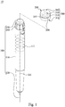
- FIG. 1 is an exploding view of an injection module 10 according to one embodiment of the disclosure
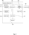
- Fig. 2 is a block diagram of the information collection device 200 of Fig. 1 .
- the information collection device 200 is used to be sleeved on an injection pen 100 to be collectively referred as an injection module 10.
- the injection pen 100 includes a syringe 110, an injection needle 120, a pressing knob 130 and a dose selection knob 140.
- the syringe 110 is formed with a spiral inner rail 111 therein.
- the injection needle 120 and the pressing knob 130 are disposed at two opposite ends of the syringe 110, respectively.
- the pressing knob 130 can be pressed to helically rotate so that an injection content (not shown) that is filled in the syringe 110 can be simultaneously pushed outwards from the syringe 110 through the injection needle 120.
- the dose selection knob 140 is located at one end of the syringe 110 that is closer to the pressing knob 130 for determining the expected injection dose by rotation.
- the injection pen 100 is an insulin injection pen.
- the pressing knob 130 When the pressing knob 130 is rotated by a user, that is, the user presses the pressing knob 130 downwardly, so that the pressing knob 130 moves along the spiral inner rail 111 with helical movement so as to gradually push the injection content (not shown) outwards from the syringe 110 through the injection needle 120.
- the pressing knob is able to be helically rotated about a shaft axis 101 of the injection pen 100. Since the injection pen is a conventional device, it will not be described again hereinafter. However, the disclosure is not limited to use on an insulin injection pen only.
- the information collection device 200 is used to record an estimated injected dose of the injection pen 100 that is supposed to be the actual injected dose of the injection pen 100.
- the information collection device 200 includes an outer cap 300, an accelerometer sensing unit 351, a gyroscope sensing unit 352, a wireless transmission unit 353 and a processing unit 354.
- the outer cap 300 is used for coupling to the pressing knob 130 of the injection pen 100.
- the accelerometer sensing unit 351 is disposed on the outer cap 300 for sensing a traveling movement of the injection pen 100 with the movement information of the injection pen 100.
- the movement information of the injection pen 100 is, for example, the moving direction and acceleration information of the injection pen 100, and the like.
- the gyroscope sensing unit 352 is disposed on the outer cap 300 for sensing an action of the pressing knob 130 to obtain the rotation information of the pressing knob 130.
- the rotation information of the pressing knob 130 is, for example, a rotational angular velocity, and the rotation information can be converted into a rotation starting point and a rotation endpoint of a rotation variable. It is noted, different actual injection doses of the injection content (not shown) can be respectively corresponded to different rotation variables of the pressing knob 130 that is rotated.
- the wireless transmission unit 353 is electrically connected to the gyroscope sensing unit 352 and the accelerometer sensing unit 351 for wirelessly connecting to an external device 360.
- the wireless transmission unit 353 is, for example, a radio frequency (RF) transmitting unit.
- RF radio frequency
- the processing unit 354 is electrically connected to the wireless transmission unit 353, the gyroscope sensing unit 352 and the accelerometer sensing unit 351.
- the processing unit 354 determines whether the traveling movement of the injection pen is conformed as an intending injection action, or other non-intending injection action such as accidental touch, movement and alike.
- the processing unit 354 instructs the wireless transmission unit 353 to transfer an actual injected dose of the injection content that is injected from the injection pen 100 to the external device 360 for recording the actual injected dose to the external device 360. More specifically, the processing unit 354 calculates an actual injection dose of the injection content being pushed outwards from the injection pen 100 according to the rotation information (e.g., rotation amount) of the pressing knob 130. The processing unit 354 instructs the radio frequency (RF) transmitting unit to transfer the actual injected dose of the injection content to the external device 360.
- RF radio frequency
- the external device 360 is, for example, a portable device (e.g., smart mobile phone or notebook computer) or a cloud device (e.g., server) or the like.
- the processing unit 354 may not process the rotation information into the actual injection dose first, and transfer the rotation information to the external device 360 through the wireless transmission unit 353 so that the external device 360 can process the rotation information into the actual injection dose by itself.
- Fig. 3 is a partial cross-sectional view of the injection module 10 of Fig. 1 .
- the information collection device 200 further includes a circuit board 350 and a trigger switch 355.
- the circuit board 350 is fixed in the outer cap 300, and the processing unit 354, the wireless transmission unit 353, the gyroscope sensing unit 352 and the accelerometer sensing unit 351 are respectively fixed on the circuit board 350.
- the processing unit 354, the wireless transmission unit 353, the gyroscope sensing unit 352 and the accelerometer sensing unit 351 are respectively soldered on the circuit board 350, and are electrically connected to each other.
- the trigger switch 355 is fixedly connected to the circuit board 350, and electrically connected to the processing unit 354, the gyroscope sensing unit 352, the accelerometer sensing unit 351 and the wireless transmission unit 353 for triggering the processing unit 354, the gyroscope sensing unit 352, the accelerometer sensing unit 351 and the wireless transmission unit 353.
- the outer cap 300 further includes a cover body 310, a joint portion 320, an opening 330 and a button body 340.
- the cover body 310 is formed with a receiving recess 311 at one end of the cover body 310, and the pressing knob 130, the processing unit 354, the wireless transmission unit 353, the gyroscope sensing unit 352 and the accelerometer sensing unit 351 are received within the receiving recess 311.
- the joint portion 320 is formed at the end of the cover body 310 for removably coupling to the pressing knob 130 of the injection pen 100.
- the opening 330 is formed at one end being opposite to the cover body 310, and the receiving recess 311 is connected to the joint portion 320 and the opening 330.
- the button body 340 is movably disposed in the receiving recess 311, and one end of the button body 340 extends outwards from the end of the cover body 310 via the opening 330, and the other end of the button body 340 abuts against the trigger switch 355 in the receiving recess 311.
- the information collection device 200 further includes a battery unit 356, a power button 357 and an indicator light 358.
- the battery unit 356 is electrically connected to the processing unit 354, the wireless transmission unit 353, the gyroscope sensing unit 352, the accelerometer sensing unit 351, the power button 357 and the indicator light 358 through the circuit board 350 to respectively provide corresponding power supplies.
- Indicator light 358 is used to indicate the operating status.
- the accelerometer sensing unit 351 and the gyroscope sensing unit 352 may be integrally combined into a single package structure, for example, a six-axis sensor, however, the disclosure is not limited thereto.
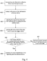
- Fig. 4 is an operation flow chart of the injection module 10 of Fig. 1 .
- the user uses the injection module 10 according to the following step 401 to step 407.
- step 401 a user incorporates the information collection device 200 onto the injection pen 100.
- step 402 the user turns on the power of the information collection device 200. More specifically, the power button 357 is pressed so that the information collection device 200 starts to stand by to wait for subsequent triggering.
- step 403 the user adjusts the expected injection dose of the injection pen 100 by rotating the dose selection knob 140.
- the user presses the button body 340 of the outer cap 300, thereby pressing the trigger switch 355.
- step 405 when the user wants to inject the above-described injection pen 100, the user presses the trigger switch 355 through the button body 340 and presses the knob 130.
- step 405 when the pressing knob 130 is rotated by the user, the processing unit 354 starts to determine whether the user's pressing action on the injection pen 100 belongs to the intending injection action under the will. If yes, go to step 406; otherwise, perform the step 407.
- step 406 the actual injected dose of the injection pen 100 that is an estimated injected dose, is transmitted (or uploaded) to the external device 360 for recording the actual injected dose.
- step 407 the actual injected dose of the injection pen 100 is set to be invalid data, and is not passed to the external device 360 or not recorded.
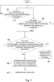
- Fig. 5 is a flow chart of an information collection method for an injection pen 100 according to one embodiment of the disclosure.
- the information collection method (i.e., step 405) for the injection pen 100 includes step 501 to step 506 as follows.
- step 501 the action of the pressing knob 130 is sensed to determine whether the rotation information of the pressing knob 130 is obtained.
- step 502 the traveling movement of the injection pen 100 is sensed to determine whether the movement information of the injection pen 100 is obtained.
- step 503 a determination is made as to whether the traveling movement of the injection pen 100 is conformed as an intending injection action according to the rotation information of the pressing knob and the movement information of the injection pen 100; if, yes, perform step 504, otherwise, perform step 506.
- step 504 the actual injection dose that the injection content is pushed outwards from the injection pen 100 is calculated according to the rotation information of the pressing knob 130.
- step 505 the actual injection dose that the injection content is pushed outwards from the injection pen 100 is recorded.
- step 506 the rotation information of the pressing knob 130 is set to be invalid data.
- step 501 to step 506 are the detailed steps of the abovementioned step 405.
- the processing unit 354 starts to perform the above-described step 501 to step 506.
- the rotation information of the pressing knob 130 is sensed by the gyroscope sensing unit 352.
- the rotation information of the pressing knob 130 is a rotational angular velocity, and the rotation information can be converted into a rotation starting point and a rotation endpoint of a rotation variable.
- Different actual injection doses of the injection content (not shown) can be respectively corresponded to different rotation variables of the pressing knob 130 that is rotated.
- step 502 further includes a step of the movement information of the injection pen 100 is sensed by the accelerometer sensing unit 351.
- the movement information of the injection pen 100 is, for example, the moving direction and acceleration information of the injection pen 100, and the like.
- the step 503 further includes the current rotation variable that is obtained through a rotation starting point and a rotation endpoint of the rotation information; and a determination is made as to whether the current rotation variable is within a predetermined range, and/or the rotational angular velocity is within a predetermined range. If so, it is determined that the rotation variable and the rotational angular velocity of the pressing knob 130 are valid data, otherwise, perform step 506.
- step 503 further includes a determination is made as to whether the travelling information is greater than a predetermined range through the sensing information of the accelerometer sensing unit 351. If so, the traveling movement of the injection pen 100 not conformed as the intending injection action is decided, for example, the traveling movement of the injection pen100 merely is shaking or accidentally touching the trigger switch 355. Otherwise, the traveling movement of the injection pen 100 conformed as the intending injection action is decided, for example, an injection behavior.
- step 504 can be performed.
- step 505 a determination is made as to whether the injection pen 100 is travelled in a moving direction along a shaft axis 101 of the injection pen 100 through the moving direction of the travelling information of the injection pen 100. If so, the traveling movement of the injection pen 100 conformed as the intending injection action is decided, for example, the traveling movement of the injection pen 100 is an injection behavior. Otherwise, the traveling movement of the injection pen 100, for example, merely shakes or accidentally touches the trigger switch 355.
- the shaft axis 101 of the injection pen 100 is considered as one of the X-axis direction, the Y-axis direction and the Z-axis direction of the coordinate system (e.g., Z-axis direction)
- a determination is made as to whether a movement amount that the injection pen 100 is moved along the shaft axis 101 of the injection pen 100 is within a predetermined range; if so, a determination is made as to whether the movement amount that the injection pen 100 is moved along the shaft axis 101 of the injection pen 100 is greater than another two of the X-axis direction, the Y-axis direction and the Z-axis direction of the coordinate system (e.g., X and Y-axis directions); if so, the current traveling movement of the injection pen 100 is decided as a purposely action.
- a coordinate system for example, Cartesian coordinate system
- step 504 the method mentioned above further includes several steps as follows.
- the rotational angular velocity collected by pressing the pressing knob 130 is converted into an expected injection dose of the injection content; and the expected injection dose of the injection content is wirelessly transmitted to the external device 360 for checking the consistency of the actual injected dose and the expected injected dose.
- step 504 mentioned above may be completed in the information collection device 200 or may be completed by the external device 360.
Landscapes
- Health & Medical Sciences (AREA)
- Engineering & Computer Science (AREA)
- General Health & Medical Sciences (AREA)
- Biomedical Technology (AREA)
- Public Health (AREA)
- Animal Behavior & Ethology (AREA)
- Veterinary Medicine (AREA)
- Vascular Medicine (AREA)
- Anesthesiology (AREA)
- Heart & Thoracic Surgery (AREA)
- Hematology (AREA)
- Life Sciences & Earth Sciences (AREA)
- Medical Informatics (AREA)
- Primary Health Care (AREA)
- Epidemiology (AREA)
- General Business, Economics & Management (AREA)
- Business, Economics & Management (AREA)
- Chemical & Material Sciences (AREA)
- Bioinformatics & Cheminformatics (AREA)
- Medicinal Chemistry (AREA)
- Infusion, Injection, And Reservoir Apparatuses (AREA)
Abstract
Description
- The disclosure relates to an information collection device and its information collection method. More particularly, the disclosure relates to an information collection device of an injection pen and its information collection method.
- In general, since diabetic patients need to inject insulin for the treatment of diabetes once or several times per day, most of them prefers to use a disposable insulin pen which is pre-filled therein so as to inject insulin to the body on their own.
- However, an intelligent management system for insulin therapy provided by the current industry is unable to read the injection dose of the insulin injection pen injected on the diabetic patient, and unable to confirm whether the insulin injection pen has completed the intending injection action. Thus, the objective of the intelligent management system for diabetic patients is still not humanized, and the intelligent management system may cause many inconveniences and problems, thereby reducing the user's willingness to use.
- In one embodiment of the disclosure, an information collection method for an injection pen, which is implemented on an information collection device coupled to a pressing knob of the injection pen, and the pressing knob is able to be pressed to helically rotate on the injection pen so that an injection content is pushed outwards from the injection pen, and the information collection method includes several steps as follows. The action of the pressing knob is sensed to determine whether the rotation information of the pressing knob is obtained. The traveling movement of the injection pen is sensed to determine whether the movement information of the injection pen is obtained. A determination is made as to whether the traveling movement of the injection pen is conformed as an intending injection action according to the rotation information of the pressing knob and the movement information of the injection pen. When the traveling movement of the injection pen is conformed as the intending injection action, an actual injection dose that the injection content is pushed outwards from the injection pen is calculated according to the rotation information of the pressing knob. The actual injection dose that the injection content is pushed outwards from the injection pen is recorded.
- According to one or more embodiments of the disclosure, in the information collection method for the injection pen, when the traveling movement of the injection pen not conformed as the intending injection action is determined, the rotation information of the pressing knob is set to be invalid data, and the actual injection dose is not recorded.
- According to one or more embodiments of the disclosure, in the information collection method for the injection pen, when a determination is made as to whether the traveling movement of the injection pen being conformed as the intending injection action, the information collection method further includes several steps as follows. A determination is made as to whether the acceleration information of the injection pen is in a predetermined range. When the acceleration information of the injection pen not in the predetermined range is determined, the traveling movement of the injection pen not conformed to be the intending injection action is decided.
- According to one or more embodiments of the disclosure, in the information collection method for the injection pen, when a determination is made as to whether the traveling movement of the injection pen being conformed as the intending injection action, the information collection method further includes several steps as follows. A determination is made as to whether the injection pen is travelled in a moving direction along a shaft axis of the injection pen. When the injection pen not travelled in the moving direction along the shaft axis of the injection pen is determined, the traveling movement of the injection pen not conformed to be the intending injection action is decided.
- According to one or more embodiments of the disclosure, in the information collection method for the injection pen, when a determination is made as to whether the traveling movement of the injection pen is conformed as the intending injection action according to the rotation information of the pressing knob and the movement information of the injection pen, the information collection method further includes several steps as follows. A determination is made as to whether a rotational angular velocity of the pressing knob is obtained. When the rotational angular velocity of the pressing knob been obtained is determined, a determination is made as to whether the injection pen is travelled in a moving direction along a Z-axis direction of a coordinate system. When the injection pen travelled in a moving direction along the Z-axis direction of the coordinate system, a determination is made as to whether a magnitude of the injection pen that is travelled in the moving direction along one of an X-axis direction and a Y-axis direction of the coordinate system is zero. When the magnitude of the injection pen that is travelled in the moving direction along one of the X-axis direction and the Y-axis direction of the coordinate system is zero is determined, the traveling movement of the injection pen being conformed as the intending injection action is decided.
- In another embodiment of the disclosure, an information collection device for an injection pen includes an outer cap, an accelerometer sensing unit, a gyroscope sensing unit, a wireless transmission unit and a processing unit. The outer cap is used for coupling to a pressing knob of the injection pen, and the pressing knob is able to be pressed to helically rotate on the injection pen so that the injection content is pushed outwards from the injection pen. The accelerometer sensing unit is disposed on the outer cap for sensing a traveling movement of the injection pen to obtain the movement information of the injection pen. The gyroscope sensing unit is disposed on the outer cap for sensing an action of the pressing knob to obtain the rotation information of the pressing knob. The wireless transmission unit is electrically connected to the gyroscope sensing unit and the accelerometer sensing unit for wirelessly connecting to an external device. The processing unit is electrically connected to the wireless transmission unit, the gyroscope sensing unit and the accelerometer sensing unit. When the pressing knob is pressed to helically rotate, the processing unit determines whether the traveling movement of the injection pen is conformed as an intending injection action according to the rotation information of the pressing knob and the movement information of the injection pen. When the processing unit determines that the traveling movement of the injection pen is conformed as the intending injection action, the processing unit instructs the wireless transmission unit to transmit one of the rotation information of the pressing knob and an actual injection dose of the injection content being pushed outwards from the injection pen to the external device.
- According to one or more embodiments of the disclosure, the information collection device further includes a circuit board and a trigger switch. The circuit board is fixed in the outer cap, and the processing unit, the wireless transmission unit, the gyroscope sensing unit and the accelerometer sensing unit are respectively fixed on the circuit board. The trigger switch is fixedly connected to the circuit board, and electrically connected to the processing unit, the gyroscope sensing unit, the accelerometer sensing unit and the wireless transmission unit for triggering the processing unit, the gyroscope sensing unit, the accelerometer sensing unit and the wireless transmission unit.
- According to one or more embodiments of the disclosure, in the information collection device, the outer cap further includes a cover body, a joint portion, an opening and a button body. The cover body is formed with a receiving recess at one end of the cover body, and the pressing knob, the processing unit, the wireless transmission unit, the gyroscope sensing unit and the accelerometer sensing unit are received within the receiving recess. The joint portion is formed at the end of the cover body for removably coupling to the pressing knob of the injection pen. The opening is formed at one end being opposite to the cover body, and the receiving recess is connected to the joint portion and the opening. The button body is movably disposed in the receiving recess, and one end of the button body extends outwards from the end of the cover body via the opening, and the other end of the button body abuts against the trigger switch in the receiving recess.
- According to one or more embodiments of the disclosure, in the information collection device, the processing unit determines whether the acceleration information of the injection pen is in a predetermined range. When the processing unit determines that the acceleration information of the injection pen is not in the predetermined range, the processing unit decides that the traveling movement of the injection pen is not conformed to be the intending injection action.
- According to one or more embodiments of the disclosure, in the information collection device, the processing unit determines whether the injection pen is travelled in a moving direction along a shaft axis of the injection pen. When the processing unit determines that the injection pen is not travelled in the moving direction along the shaft axis of the injection pen, the processing unit decides that the traveling movement of the injection pen is not conformed to be the intending injection action.
- Thus, through the construction of the embodiments above, not only the actual injection dose of the injection pen can be accurately recorded, but also a confirmation can be made as to whether the injection pen has completed the intending injection action, thereby avoiding recording false values from non-injection behavior. Therefore, the user-friendly design is improved, and the inconvenience and troubles described above are solved, thereby increasing the user's willingness to use.
- The above description is merely used for illustrating the problems to be resolved, the technical methods for resolving the problems and their efficacies, etc. The specific details of the disclosure will be explained in the embodiments below and related drawings.
- The accompanying drawings are included to provide a further understanding of the disclosure, and are incorporated in and constitute a part of this specification. The drawings illustrate embodiments of the disclosure and, together with the description, serve to explain the principles of the disclosure. In the drawings,
-
Fig. 1 is an exploding view of an injection module according to one embodiment of the disclosure; -
Fig. 2 is a block diagram of the information collection device ofFig. 1 ; -
Fig. 3 is a partial cross-sectional view of the injection module ofFig. 1 ; -
Fig. 4 is an operation flow chart of the injection module ofFig. 1 ; and -
Fig. 5 is a flow chart of an information collection method for an injection pen according to one embodiment of the disclosure. - Reference is now made to
Fig. 1 andFig. 2 , in whichFig. 1 is an exploding view of aninjection module 10 according to one embodiment of the disclosure, andFig. 2 is a block diagram of theinformation collection device 200 ofFig. 1 . As shown inFig. 1 andFig. 2 , theinformation collection device 200 is used to be sleeved on aninjection pen 100 to be collectively referred as aninjection module 10. Theinjection pen 100 includes asyringe 110, aninjection needle 120, apressing knob 130 and adose selection knob 140. Thesyringe 110 is formed with a spiralinner rail 111 therein. Theinjection needle 120 and thepressing knob 130 are disposed at two opposite ends of thesyringe 110, respectively. Thepressing knob 130 can be pressed to helically rotate so that an injection content (not shown) that is filled in thesyringe 110 can be simultaneously pushed outwards from thesyringe 110 through theinjection needle 120. Thedose selection knob 140 is located at one end of thesyringe 110 that is closer to thepressing knob 130 for determining the expected injection dose by rotation. - In this embodiment, for example, the
injection pen 100 is an insulin injection pen. When thepressing knob 130 is rotated by a user, that is, the user presses thepressing knob 130 downwardly, so that thepressing knob 130 moves along the spiralinner rail 111 with helical movement so as to gradually push the injection content (not shown) outwards from thesyringe 110 through theinjection needle 120. The pressing knob is able to be helically rotated about ashaft axis 101 of theinjection pen 100. Since the injection pen is a conventional device, it will not be described again hereinafter. However, the disclosure is not limited to use on an insulin injection pen only. - When the intending injection action is completed, the
information collection device 200 is used to record an estimated injected dose of theinjection pen 100 that is supposed to be the actual injected dose of theinjection pen 100. In short, theinformation collection device 200 includes anouter cap 300, anaccelerometer sensing unit 351, agyroscope sensing unit 352, awireless transmission unit 353 and aprocessing unit 354. Theouter cap 300 is used for coupling to thepressing knob 130 of theinjection pen 100. Theaccelerometer sensing unit 351 is disposed on theouter cap 300 for sensing a traveling movement of theinjection pen 100 with the movement information of theinjection pen 100. The movement information of theinjection pen 100 is, for example, the moving direction and acceleration information of theinjection pen 100, and the like. Thegyroscope sensing unit 352 is disposed on theouter cap 300 for sensing an action of thepressing knob 130 to obtain the rotation information of thepressing knob 130. The rotation information of thepressing knob 130 is, for example, a rotational angular velocity, and the rotation information can be converted into a rotation starting point and a rotation endpoint of a rotation variable. It is noted, different actual injection doses of the injection content (not shown) can be respectively corresponded to different rotation variables of thepressing knob 130 that is rotated. Thewireless transmission unit 353 is electrically connected to thegyroscope sensing unit 352 and theaccelerometer sensing unit 351 for wirelessly connecting to anexternal device 360. Thewireless transmission unit 353 is, for example, a radio frequency (RF) transmitting unit. Theprocessing unit 354 is electrically connected to thewireless transmission unit 353, thegyroscope sensing unit 352 and theaccelerometer sensing unit 351. Thus, when the aforementionedpressing knob 130 is pressed down to helically rotate by a user, according to the rotation information of the pressing knob and the movement information of the injection pen, theprocessing unit 354 determines whether the traveling movement of the injection pen is conformed as an intending injection action, or other non-intending injection action such as accidental touch, movement and alike. When theprocessing unit 354 decides that the traveling movement of the injection pen is conformed as the intending injection action, theprocessing unit 354 instructs thewireless transmission unit 353 to transfer an actual injected dose of the injection content that is injected from theinjection pen 100 to theexternal device 360 for recording the actual injected dose to theexternal device 360. More specifically, theprocessing unit 354 calculates an actual injection dose of the injection content being pushed outwards from theinjection pen 100 according to the rotation information (e.g., rotation amount) of thepressing knob 130. Theprocessing unit 354 instructs the radio frequency (RF) transmitting unit to transfer the actual injected dose of the injection content to theexternal device 360. Theexternal device 360 is, for example, a portable device (e.g., smart mobile phone or notebook computer) or a cloud device (e.g., server) or the like. However, the disclosure is not limited thereto. In other embodiments, theprocessing unit 354 may not process the rotation information into the actual injection dose first, and transfer the rotation information to theexternal device 360 through thewireless transmission unit 353 so that theexternal device 360 can process the rotation information into the actual injection dose by itself. -
Fig. 3 is a partial cross-sectional view of theinjection module 10 ofFig. 1 . As shown inFig. 2 andFig. 3 , in the embodiment, theinformation collection device 200 further includes acircuit board 350 and atrigger switch 355. Thecircuit board 350 is fixed in theouter cap 300, and theprocessing unit 354, thewireless transmission unit 353, thegyroscope sensing unit 352 and theaccelerometer sensing unit 351 are respectively fixed on thecircuit board 350. For example, theprocessing unit 354, thewireless transmission unit 353, thegyroscope sensing unit 352 and theaccelerometer sensing unit 351 are respectively soldered on thecircuit board 350, and are electrically connected to each other. Thetrigger switch 355 is fixedly connected to thecircuit board 350, and electrically connected to theprocessing unit 354, thegyroscope sensing unit 352, theaccelerometer sensing unit 351 and thewireless transmission unit 353 for triggering theprocessing unit 354, thegyroscope sensing unit 352, theaccelerometer sensing unit 351 and thewireless transmission unit 353. - Furthermore, more specifically, the
outer cap 300 further includes acover body 310, ajoint portion 320, anopening 330 and abutton body 340. Thecover body 310 is formed with a receivingrecess 311 at one end of thecover body 310, and thepressing knob 130, theprocessing unit 354, thewireless transmission unit 353, thegyroscope sensing unit 352 and theaccelerometer sensing unit 351 are received within the receivingrecess 311. Thejoint portion 320 is formed at the end of thecover body 310 for removably coupling to thepressing knob 130 of theinjection pen 100. Theopening 330 is formed at one end being opposite to thecover body 310, and the receivingrecess 311 is connected to thejoint portion 320 and theopening 330. Thebutton body 340 is movably disposed in the receivingrecess 311, and one end of thebutton body 340 extends outwards from the end of thecover body 310 via theopening 330, and the other end of thebutton body 340 abuts against thetrigger switch 355 in the receivingrecess 311. - Moreover, the
information collection device 200 further includes abattery unit 356, apower button 357 and anindicator light 358. Thebattery unit 356 is electrically connected to theprocessing unit 354, thewireless transmission unit 353, thegyroscope sensing unit 352, theaccelerometer sensing unit 351, thepower button 357 and the indicator light 358 through thecircuit board 350 to respectively provide corresponding power supplies.Indicator light 358 is used to indicate the operating status. - Also, in the embodiment, the
accelerometer sensing unit 351 and thegyroscope sensing unit 352 may be integrally combined into a single package structure, for example, a six-axis sensor, however, the disclosure is not limited thereto. -
Fig. 4 is an operation flow chart of theinjection module 10 ofFig. 1 . As shown inFig. 2 andFig. 3 , in the embodiment, the user uses theinjection module 10 according to the followingstep 401 to step 407. Instep 401, a user incorporates theinformation collection device 200 onto theinjection pen 100. Instep 402, the user turns on the power of theinformation collection device 200. More specifically, thepower button 357 is pressed so that theinformation collection device 200 starts to stand by to wait for subsequent triggering. Instep 403, the user adjusts the expected injection dose of theinjection pen 100 by rotating thedose selection knob 140. Instep 404, the user presses thebutton body 340 of theouter cap 300, thereby pressing thetrigger switch 355. More specifically, when the user wants to inject the above-describedinjection pen 100, the user presses thetrigger switch 355 through thebutton body 340 and presses theknob 130. Instep 405, when thepressing knob 130 is rotated by the user, theprocessing unit 354 starts to determine whether the user's pressing action on theinjection pen 100 belongs to the intending injection action under the will. If yes, go to step 406; otherwise, perform thestep 407. In step 406, the actual injected dose of theinjection pen 100 that is an estimated injected dose, is transmitted (or uploaded) to theexternal device 360 for recording the actual injected dose. - In
step 407, the actual injected dose of theinjection pen 100 is set to be invalid data, and is not passed to theexternal device 360 or not recorded. -
Fig. 5 is a flow chart of an information collection method for aninjection pen 100 according to one embodiment of the disclosure. As shown inFig. 5 , in the embodiment, the information collection method (i.e., step 405) for theinjection pen 100 includesstep 501 to step 506 as follows. Instep 501, the action of thepressing knob 130 is sensed to determine whether the rotation information of thepressing knob 130 is obtained. Instep 502, the traveling movement of theinjection pen 100 is sensed to determine whether the movement information of theinjection pen 100 is obtained. Instep 503, a determination is made as to whether the traveling movement of theinjection pen 100 is conformed as an intending injection action according to the rotation information of the pressing knob and the movement information of theinjection pen 100; if, yes, performstep 504, otherwise, performstep 506. Instep 504, the actual injection dose that the injection content is pushed outwards from theinjection pen 100 is calculated according to the rotation information of thepressing knob 130. Instep 505, the actual injection dose that the injection content is pushed outwards from theinjection pen 100 is recorded. Instep 506, the rotation information of thepressing knob 130 is set to be invalid data. For example, step 501 to step 506 are the detailed steps of theabovementioned step 405. - As shown in
Fig. 2 and5 , in the disclosure, when thepressing knob 130 is triggered, theprocessing unit 354 starts to perform the above-describedstep 501 to step 506. - More specifically, in
step 501, the rotation information of thepressing knob 130 is sensed by thegyroscope sensing unit 352. For example, the rotation information of thepressing knob 130 is a rotational angular velocity, and the rotation information can be converted into a rotation starting point and a rotation endpoint of a rotation variable. Different actual injection doses of the injection content (not shown) can be respectively corresponded to different rotation variables of thepressing knob 130 that is rotated. - In this embodiment, more specifically, step 502 further includes a step of the movement information of the
injection pen 100 is sensed by theaccelerometer sensing unit 351. The movement information of theinjection pen 100 is, for example, the moving direction and acceleration information of theinjection pen 100, and the like. - In this embodiment, more specifically, the
step 503 further includes the current rotation variable that is obtained through a rotation starting point and a rotation endpoint of the rotation information; and a determination is made as to whether the current rotation variable is within a predetermined range, and/or the rotational angular velocity is within a predetermined range. If so, it is determined that the rotation variable and the rotational angular velocity of thepressing knob 130 are valid data, otherwise, performstep 506. - In this embodiment, more specifically, when the rotation variable and the rotational angular velocity of the
pressing knob 130 are determined as the valid data, step 503 further includes a determination is made as to whether the travelling information is greater than a predetermined range through the sensing information of theaccelerometer sensing unit 351. If so, the traveling movement of theinjection pen 100 not conformed as the intending injection action is decided, for example, the traveling movement of the injection pen100 merely is shaking or accidentally touching thetrigger switch 355. Otherwise, the traveling movement of theinjection pen 100 conformed as the intending injection action is decided, for example, an injection behavior. - Thus, since the rotation variable of the
pressing knob 130 is valid data, and the traveling movement of theinjection pen 100 is decided to be the intending injection action, thus, step 504 can be performed. - However, the disclosure is not limited thereto, in other embodiment, in
step 505, more particularly, a determination is made as to whether theinjection pen 100 is travelled in a moving direction along ashaft axis 101 of theinjection pen 100 through the moving direction of the travelling information of theinjection pen 100. If so, the traveling movement of theinjection pen 100 conformed as the intending injection action is decided, for example, the traveling movement of theinjection pen 100 is an injection behavior. Otherwise, the traveling movement of theinjection pen 100, for example, merely shakes or accidentally touches thetrigger switch 355. - In more detail, when the
shaft axis 101 of theinjection pen 100 is considered as one of the X-axis direction, the Y-axis direction and the Z-axis direction of the coordinate system (e.g., Z-axis direction), a determination is made as to whether a movement amount that theinjection pen 100 is moved along theshaft axis 101 of theinjection pen 100 is within a predetermined range; if so, a determination is made as to whether the movement amount that theinjection pen 100 is moved along theshaft axis 101 of theinjection pen 100 is greater than another two of the X-axis direction, the Y-axis direction and the Z-axis direction of the coordinate system (e.g., X and Y-axis directions); if so, the current traveling movement of theinjection pen 100 is decided as a purposely action. In addition, when the rotational angular velocity collected from the rotation of theinjection pen 100 is decided, a determination is further made as to whether the moving direction of theinjection pen 100 is moved along the Z-axis direction of a coordinate system (for example, Cartesian coordinate system), if so, a determination is further made as to whether a magnitude of theinjection pen 100 that is travelled in the moving direction along an X-axis direction or a Y-axis direction of the coordinate system is zero, the current traveling movement of theinjection pen 100 is decided as a purposely action, for example, injection action. - Furthermore, more specifically, after
step 504, the method mentioned above further includes several steps as follows. The rotational angular velocity collected by pressing thepressing knob 130 is converted into an expected injection dose of the injection content; and the expected injection dose of the injection content is wirelessly transmitted to theexternal device 360 for checking the consistency of the actual injected dose and the expected injected dose. - It is noted, the
step 504 mentioned above may be completed in theinformation collection device 200 or may be completed by theexternal device 360. - Thus, through the construction of the embodiments above, not only the actual injection dose of the injection pen can be accurately recorded, but also a confirmation can be made as to whether the injection pen has completed the intending injection action, thereby avoiding recording false values from non-injection behavior. Therefore, the user-friendly design is improved, and the inconvenience and troubles described above are solved, thereby increasing the user's willingness to use.
- It will be apparent to those skilled in the art that various modifications and variations can be made to the structure of the disclosure without departing from the scope or spirit of the disclosure. In view of the foregoing, it is intended that the disclosure cover modifications and variations of this disclosure provided they fall within the scope of the following claims and their equivalents.
Claims (10)
- An information collection method for an injection pen (100), which is implemented on an information collection device (300) coupled to a pressing knob (130) of the injection pen (100), and the pressing knob (130) is able to be pressed to helically rotate on the injection pen (100) so that an injection content is pushed outwards from the injection pen (100), and the information collection method characterized by comprising:sensing an action of the pressing knob (130) to determine whether a rotation information of the pressing knob (130) is obtained;sensing a traveling movement of the injection pen (100) to determine whether a movement information of the injection pen (100) is obtained;determining whether the traveling movement of the injection pen (100) is conformed as an intending injection action according to the rotation information of the pressing knob (130) and the movement information of the injection pen (100); andwhen determining that the traveling movement of the injection pen (100) is conformed as the intending injection action, calculating an actual injection dose that the injection content is pushed outwards from the injection pen (100) according to the rotation information of the pressing knob (130); andrecording the actual injection dose that the injection content is pushed outwards from the injection pen (100).
- The information collection method for the injection pen (100) of claim 1, characterized in that when determining that the traveling movement of the injection pen (100) is not conformed as the intending injection action, setting the rotation information of the pressing knob (130) to be invalid data, and the actual injection dose is not recorded.
- The information collection method for the injection pen (100) of claim 2, characterized in that determining whether the traveling movement of the injection pen (100) is conformed as the intending injection action according to the rotation information of the pressing knob (130) and the movement information of the injection pen (100), further comprises:determining whether an acceleration information of the injection pen (100) is in a predetermined range; andwhen determining that the acceleration information of the injection pen (100) is not in the predetermined range, deciding the traveling movement of the injection pen (100) is not conformed to be the intending injection action.
- The information collection method for the injection pen (100) of claim 2, characterized in that determining whether the traveling movement of the injection pen (100) is conformed as the intending injection action according to the rotation information of the pressing knob (130) and the movement information of the injection pen (100), further comprises:determining whether the injection pen (100) is travelled in a moving direction along a shaft axis (101) of the injection pen (100); andwhen determining that the injection pen (100) is not travelled in the moving direction along the shaft axis (101) of the injection pen (100), deciding the traveling movement of the injection pen (100) is not conformed to be the intending injection action.
- The information collection method for the injection pen (100) of claim 1, characterized in that determining whether the traveling movement of the injection pen (100) is conformed as the intending injection action according to the rotation information of the pressing knob (130) and the movement information of the injection pen (100), further comprises:determining whether a rotational angular velocity of the pressing knob (130) is obtained;when determining that the rotational angular velocity of the pressing knob (130) is obtained, determining whether the injection pen (100) is travelled in a moving direction along a Z-axis direction of a coordinate system;when determining that the injection pen (100) is travelled in the moving direction along the Z-axis direction of the coordinate system, determining whether a magnitude of the injection pen (100) that is travelled in the moving direction along one of an X-axis direction and a Y-axis direction of the coordinate system is zero; andwhen determining that the magnitude of the injection pen (100) being travelled in the moving direction along one of the X-axis direction and the Y-axis direction of the coordinate system is zero, deciding the traveling movement of the injection pen (100) is conformed as the intending injection action.
- An information collection device (300) for an injection pen (100), characterized by comprising:an outer cap (300) for coupling to a pressing knob (130) of the injection pen (100), wherein the pressing knob (130) is able to be pressed to helically rotate on the injection pen (100) so that an injection content is pushed outwards from the injection pen (100);an accelerometer sensing unit (351) that is disposed on the outer cap (300) for sensing a traveling movement of the injection pen (100) to obtain a movement information of the injection pen (100);a gyroscope sensing unit (352) that is disposed on the outer cap (300) for sensing an action of the pressing knob (130) to obtain a rotation information of the pressing knob (130);a wireless transmission unit (353) that is electrically connected to the gyroscope sensing unit (352) and the accelerometer sensing unit (351) for wirelessly connecting to an external device (360); anda processing unit (354) that is electrically connected to the wireless transmission unit (353), the gyroscope sensing unit (352) and the accelerometer sensing unit (351),wherein when the pressing knob (130) is pressed to helically rotate, the processing unit (354) determines whether the traveling movement of the injection pen (100) is conformed as an intending injection action according to the rotation information of the pressing knob (130) and the movement information of the injection pen (100); andwhen the processing unit (354) determines that the traveling movement of the injection pen (100) is conformed as the intending injection action, the processing unit (354) instructs the wireless transmission unit (353) to transmit one of the rotation information of the pressing knob (130) and an actual injection dose of the injection content being pushed outwards from the injection pen (100) to the external device (360).
- The information collection device for the injection pen (100) of claim 6, further characterized by comprising:a circuit board (350) that is fixed in the outer cap (300), wherein the processing unit (354), the wireless transmission unit (353), the gyroscope sensing unit (352) and the accelerometer sensing unit (351) are respectively fixed on the circuit board (350); anda trigger switch (355) that is fixedly connected to the circuit board (350), and electrically connected to the processing unit (354), the gyroscope sensing unit (352), the accelerometer sensing unit (351) and the wireless transmission unit (353) for triggering the processing unit (354), the gyroscope sensing unit (352), the accelerometer sensing unit (351) and the wireless transmission unit (353).
- The information collection device (300)for the injection pen (100) of claim 7, characterized in that the outer cap (300) comprising:a cover body (310) that is formed with a receiving recess (311) at one end of the cover body (310), wherein the pressing knob (130), the processing unit (354), the wireless transmission unit (353), the gyroscope sensing unit (352) and the accelerometer sensing unit (351) are received within the receiving recess (311);a joint portion (320) that is formed at the end of the cover body (310) for removably coupling to the pressing knob (130) of the injection pen (100);an opening (330) that is formed at one end being opposite to the cover body (310), wherein the receiving recess (311) is connected to the joint portion (320) and the opening (310); anda button body (340) that is movably disposed in the receiving recess (311), and one end of the button body (340) extends outwards from the end of the cover body (310) via the opening (310), and the other end of the button body (340) abuts against the trigger switch (355) in the receiving recess (311).
- The information collection device for the injection pen (100) of claim 6, characterized in that the processing unit (354) determines whether an acceleration information of the injection pen (100) is in a predetermined range, and
when the processing unit (354) determines that the acceleration information of the injection pen (100) is not in the predetermined range, the processing unit (354) decides that the traveling movement of the injection pen (100) is not conformed to be the intending injection action. - The information collection device(300) for the injection pen (100) of claim 6, characterized in that the processing unit (354) determines whether the injection pen (100) is travelled in a moving direction along a shaft axis (101) of the injection pen (100), and
when the processing unit (354) determines that the injection pen (100) is not travelled in the moving direction along the shaft axis (101) of the injection pen (100), the processing unit (354) decides that the traveling movement of the injection pen (100) is not conformed to be the intending injection action.
Applications Claiming Priority (1)
| Application Number | Priority Date | Filing Date | Title |
|---|---|---|---|
| TW108133664A TWI694846B (en) | 2019-09-18 | 2019-09-18 | Information collecting device of injection pen and information collecting method thereof |
Publications (1)
| Publication Number | Publication Date |
|---|---|
| EP3796329A1 true EP3796329A1 (en) | 2021-03-24 |
Family
ID=69804615
Family Applications (1)
| Application Number | Title | Priority Date | Filing Date |
|---|---|---|---|
| EP20162337.8A Pending EP3796329A1 (en) | 2019-09-18 | 2020-03-11 | Information collection device of injection pen and information collection method thereof |
Country Status (4)
| Country | Link |
|---|---|
| US (1) | US20210077731A1 (en) |
| EP (1) | EP3796329A1 (en) |
| CN (1) | CN112516415B (en) |
| TW (1) | TWI694846B (en) |
Citations (5)
| Publication number | Priority date | Publication date | Assignee | Title |
|---|---|---|---|---|
| US20110313395A1 (en) * | 2009-02-27 | 2011-12-22 | Lifescan, Inc. | Drug delivery management systems and methods |
| US20140243635A1 (en) * | 2013-02-22 | 2014-08-28 | Thuban, Inc. | Device for enabling patient self testing and treatment self- administration and system using the device for managing the patient's health care |
| US20170368265A1 (en) * | 2012-02-13 | 2017-12-28 | Sanofi-Aventis Deutschland Gmbh | Monitoring device for monitoring operation of a drug delivery device |
| WO2018104289A1 (en) * | 2016-12-07 | 2018-06-14 | Sanofi | Data collection device for attachment to an injection device |
| US20180289901A1 (en) * | 2017-04-06 | 2018-10-11 | Nordic Healthcare Advisory Aps | Position determination device and system for determining and registering an injection location |
Family Cites Families (11)
| Publication number | Priority date | Publication date | Assignee | Title |
|---|---|---|---|---|
| KR100478771B1 (en) * | 2003-03-27 | 2005-03-25 | 주식회사 엔터기술 | insulin pump |
| US7546826B2 (en) * | 2006-03-31 | 2009-06-16 | Transonic Combustion, Inc. | Injector-ignition for an internal combustion engine |
| FI20065735A0 (en) * | 2006-11-20 | 2006-11-20 | Salla Koski | Measurement, monitoring and management system and its constituent equipment |
| KR20140122272A (en) * | 2012-02-13 | 2014-10-17 | 사노피-아벤티스 도이칠란트 게엠베하 | Supplemental device for attachment to an injection device |
| CN106456884A (en) * | 2014-03-14 | 2017-02-22 | 卡贝欧洲有限公司 | monitoring device |
| JP6820264B2 (en) * | 2015-01-23 | 2021-01-27 | ベクトン・ディキンソン・アンド・カンパニーBecton, Dickinson And Company | Methods and Devices for Capturing Dosage Dialing Events |
| WO2016138634A1 (en) * | 2015-03-03 | 2016-09-09 | 创新精密仪器有限公司 | Drug information monitoring apparatus and drug information monitoring type injection apparatus |
| WO2016167330A1 (en) * | 2015-04-16 | 2016-10-20 | 株式会社根本杏林堂 | Liquid medicine injection device, method for controlling liquid medicine injection device, and computer program |
| AU2016291849B2 (en) * | 2015-07-12 | 2021-09-23 | Patients Pending Ltd. | Cover for liquid delivery system with integrated plunger position sensing, and corresponding method |
| ES2954088T3 (en) * | 2015-07-21 | 2023-11-20 | Biocorp Production SA | Dose control system for injectable drug delivery devices and associated methods of use |
| US11833333B2 (en) * | 2017-07-12 | 2023-12-05 | Insuline Medical Ltd | Drug tracking device |
-
2019
- 2019-09-18 TW TW108133664A patent/TWI694846B/en active
- 2019-10-08 CN CN201910948847.5A patent/CN112516415B/en active Active
-
2020
- 2020-01-20 US US16/747,163 patent/US20210077731A1/en not_active Abandoned
- 2020-03-11 EP EP20162337.8A patent/EP3796329A1/en active Pending
Patent Citations (5)
| Publication number | Priority date | Publication date | Assignee | Title |
|---|---|---|---|---|
| US20110313395A1 (en) * | 2009-02-27 | 2011-12-22 | Lifescan, Inc. | Drug delivery management systems and methods |
| US20170368265A1 (en) * | 2012-02-13 | 2017-12-28 | Sanofi-Aventis Deutschland Gmbh | Monitoring device for monitoring operation of a drug delivery device |
| US20140243635A1 (en) * | 2013-02-22 | 2014-08-28 | Thuban, Inc. | Device for enabling patient self testing and treatment self- administration and system using the device for managing the patient's health care |
| WO2018104289A1 (en) * | 2016-12-07 | 2018-06-14 | Sanofi | Data collection device for attachment to an injection device |
| US20180289901A1 (en) * | 2017-04-06 | 2018-10-11 | Nordic Healthcare Advisory Aps | Position determination device and system for determining and registering an injection location |
Also Published As
| Publication number | Publication date |
|---|---|
| CN112516415A (en) | 2021-03-19 |
| TWI694846B (en) | 2020-06-01 |
| US20210077731A1 (en) | 2021-03-18 |
| TW202112407A (en) | 2021-04-01 |
| CN112516415B (en) | 2022-08-26 |
Similar Documents
| Publication | Publication Date | Title |
|---|---|---|
| JP7301943B2 (en) | Status sensing system within injection device assembly | |
| US9110505B2 (en) | Wearable motion sensing computing interface | |
| US10168775B2 (en) | Wearable motion sensing computing interface | |
| EP3132821A1 (en) | Drug information monitoring apparatus and drug information monitoring type injection apparatus | |
| EP2400883B1 (en) | Drug delivery management systems and methods | |
| CN109562234A (en) | Injection dose detection device and injection dose detection system | |
| JP7612810B2 (en) | Status sensing system for connected injection devices | |
| US20210077731A1 (en) | Information Collection Device of Injection Pen and Information Collection Method Thereof | |
| KR20230173994A (en) | Monitoring and Management System for Pen Type Injection Appartus with Double IMU Sensor | |
| EP4120283A2 (en) | Secondary methods of communicating with a drug delivery device | |
| CN204563171U (en) | Drug information monitoring device and drug information monitoring formula injection device | |
| EA039706B1 (en) | Injection device | |
| KR20260008986A (en) | Monitering and Management System for Pen Type Injection Appartus | |
| EA044344B1 (en) | INJECTION DEVICE WITH STATUS DETERMINATION SENSORS |
Legal Events
| Date | Code | Title | Description |
|---|---|---|---|
| PUAI | Public reference made under article 153(3) epc to a published international application that has entered the european phase |
Free format text: ORIGINAL CODE: 0009012 |
|
| STAA | Information on the status of an ep patent application or granted ep patent |
Free format text: STATUS: THE APPLICATION HAS BEEN PUBLISHED |
|
| AK | Designated contracting states |
Kind code of ref document: A1 Designated state(s): AL AT BE BG CH CY CZ DE DK EE ES FI FR GB GR HR HU IE IS IT LI LT LU LV MC MK MT NL NO PL PT RO RS SE SI SK SM TR |
|
| AX | Request for extension of the european patent |
Extension state: BA ME |
|
| STAA | Information on the status of an ep patent application or granted ep patent |
Free format text: STATUS: REQUEST FOR EXAMINATION WAS MADE |
|
| 17P | Request for examination filed |
Effective date: 20210622 |
|
| RBV | Designated contracting states (corrected) |
Designated state(s): AL AT BE BG CH CY CZ DE DK EE ES FI FR GB GR HR HU IE IS IT LI LT LU LV MC MK MT NL NO PL PT RO RS SE SI SK SM TR |
|
| STAA | Information on the status of an ep patent application or granted ep patent |
Free format text: STATUS: EXAMINATION IS IN PROGRESS |
|
| 17Q | First examination report despatched |
Effective date: 20230929 |