EP3796257A1 - Estimation device, estimation method, and computer program product - Google Patents
Estimation device, estimation method, and computer program product Download PDFInfo
- Publication number
- EP3796257A1 EP3796257A1 EP20156871.4A EP20156871A EP3796257A1 EP 3796257 A1 EP3796257 A1 EP 3796257A1 EP 20156871 A EP20156871 A EP 20156871A EP 3796257 A1 EP3796257 A1 EP 3796257A1
- Authority
- EP
- European Patent Office
- Prior art keywords
- reliability
- estimation
- camera
- pose
- unit
- Prior art date
- Legal status (The legal status is an assumption and is not a legal conclusion. Google has not performed a legal analysis and makes no representation as to the accuracy of the status listed.)
- Pending
Links
Images




Classifications
-
- G—PHYSICS
- G06—COMPUTING OR CALCULATING; COUNTING
- G06T—IMAGE DATA PROCESSING OR GENERATION, IN GENERAL
- G06T7/00—Image analysis
- G06T7/70—Determining position or orientation of objects or cameras
-
- G—PHYSICS
- G06—COMPUTING OR CALCULATING; COUNTING
- G06T—IMAGE DATA PROCESSING OR GENERATION, IN GENERAL
- G06T7/00—Image analysis
- G06T7/20—Analysis of motion
-
- G—PHYSICS
- G06—COMPUTING OR CALCULATING; COUNTING
- G06T—IMAGE DATA PROCESSING OR GENERATION, IN GENERAL
- G06T3/00—Geometric image transformations in the plane of the image
- G06T3/40—Scaling of whole images or parts thereof, e.g. expanding or contracting
- G06T3/4007—Scaling of whole images or parts thereof, e.g. expanding or contracting based on interpolation, e.g. bilinear interpolation
-
- G—PHYSICS
- G06—COMPUTING OR CALCULATING; COUNTING
- G06T—IMAGE DATA PROCESSING OR GENERATION, IN GENERAL
- G06T7/00—Image analysis
- G06T7/20—Analysis of motion
- G06T7/246—Analysis of motion using feature-based methods, e.g. the tracking of corners or segments
-
- G—PHYSICS
- G06—COMPUTING OR CALCULATING; COUNTING
- G06T—IMAGE DATA PROCESSING OR GENERATION, IN GENERAL
- G06T7/00—Image analysis
- G06T7/20—Analysis of motion
- G06T7/277—Analysis of motion involving stochastic approaches, e.g. using Kalman filters
-
- H—ELECTRICITY
- H04—ELECTRIC COMMUNICATION TECHNIQUE
- H04N—PICTORIAL COMMUNICATION, e.g. TELEVISION
- H04N23/00—Cameras or camera modules comprising electronic image sensors; Control thereof
- H04N23/60—Control of cameras or camera modules
- H04N23/69—Control of means for changing angle of the field of view, e.g. optical zoom objectives or electronic zooming
-
- G—PHYSICS
- G06—COMPUTING OR CALCULATING; COUNTING
- G06T—IMAGE DATA PROCESSING OR GENERATION, IN GENERAL
- G06T2207/00—Indexing scheme for image analysis or image enhancement
- G06T2207/10—Image acquisition modality
- G06T2207/10016—Video; Image sequence
-
- G—PHYSICS
- G06—COMPUTING OR CALCULATING; COUNTING
- G06T—IMAGE DATA PROCESSING OR GENERATION, IN GENERAL
- G06T2207/00—Indexing scheme for image analysis or image enhancement
- G06T2207/20—Special algorithmic details
- G06T2207/20076—Probabilistic image processing
-
- G—PHYSICS
- G06—COMPUTING OR CALCULATING; COUNTING
- G06T—IMAGE DATA PROCESSING OR GENERATION, IN GENERAL
- G06T2207/00—Indexing scheme for image analysis or image enhancement
- G06T2207/30—Subject of image; Context of image processing
- G06T2207/30244—Camera pose
Definitions
- Arrangements described herein relate generally to an estimation device, an estimation method, and a computer program product.
- the movable body 10 includes an estimation device 20, an output unit 10A, a camera 10B, a sensor 10C, a power control unit 10G, and a power unit 10H.
- the movable body 10 may be any movable body. Examples of the movable body 10 include a vehicle, a carriage, and a movable robot. Examples of the vehicle include a motorcycle, an automobile, and a bicycle.
- the movable body 10 may be, for example, a movable body running through a human driving operation or may be a movable body capable of automatically driving (autonomous driving) without a human driving operation.
- the estimation device 20 is implemented, for example, by dedicated or general-purpose computer hardware.
- the estimation device 20 estimates the location indicating at least one of the position and the pose of the movable body 10. Specifically, the estimation device 20 calculates the reliability for each of the self-location estimation results obtained by different methods and compares the reliability with a preset threshold to select or integrate the self-location estimation results. This configuration can eliminate the interruption in tracking of the movable body 10.
- the estimation device 20 is not necessarily mounted on the movable body 10.
- the estimation device 20 may be mounted on a stationary object.
- the stationary object is, for example, an object unable to move, such as an object fixed to the ground.
- Examples of the stationary object fixed to the ground include a guard rail, a pole, a parked vehicle, and a road sign.
- the stationary object is an object stationary relative to the ground.
- the estimation device 20 may be installed in a cloud server that executes processing on a cloud system.
- the output unit 10A (the communication unit 10D, the display 10E, and the speaker 10F), the camera 10B, the sensor 10C, the power control unit 10G, and the storage unit 20B may be connected through a network.
- the communication system of the network used for the connection may be wired or may be wireless.
- the network used for the connection may be implemented by a combination of a wired system and a wireless system.
- processor used in the present arrangement includes CPU, graphical processing unit (GPU), application specific integrated circuit (ASIC), and programmable logic device.
- programmable logic device examples include simple programmable logic device (SPLD), complex programmable logic device (CPLD), and field programmable gate array (FPGA).
- the acquisition unit 21 acquires an image captured by the camera 10B.
- the first estimation unit 22 estimates at least one of the position and the pose of the camera 10B from the image and outputs the estimated at least one of the position and the pose as first estimation information.
- the second estimation unit 24 estimates at least one of the position and the pose of the camera 10B based on the past determination process result by the determination unit 26 and outputs the estimated at least one of the position and the pose as second estimation information. For example, the second estimation unit 24 performs estimation by applying Kalman filtering to the past determination process result output by the determination unit 26 and performing linear interpolation of the position and pose of the camera 10B at present.
- the first estimation unit 22 extracts a plurality of feature points from images and performs matching between the images to estimate the position and the pose of the camera 10B at the time when each image is captured.
- the position and the pose of the camera 10B at the time when each image is captured can be estimated by applying Structure from Motion (SfM) from a plurality of images obtained from the camera 10B mounted on the movable body 10.
- SfM Structure from Motion
- the first estimation unit 22 may apply Simultaneous Self-location and Mapping (SLAM) to an image acquired by the camera 10B to estimate the position and the pose of the camera 10B at the time when the image is captured.
- SLAM Simultaneous Self-location and Mapping
- the position and the pose can be calculated based on elementary matrices, fundamental matrices, or homography matrices, using a plurality of sets of camera coordinates of feature points.
- a plurality of feature point sets can be obtained by performing matching of the feature points between the images.
- the matching can be implemented by, for example, template matching, the Lucas-Kanade method, and SIFT.
- a process of normalizing the norm of a translation vector to 1 may be performed, or the scale may be determined by an acceleration sensor or a gyro sensor.
- the first calculation unit 23 calculates the first reliability (step S103).
- the second estimation unit 24 estimates the second estimation information using the past determination process result by the determination unit 26 (step S106). Specifically, the second estimation unit 24 estimates the position and the pose at present by filtering using the position and the pose included in the past determination process result as inputs. For example, Kalman filtering may be used as the filtering. The second estimation unit 24 may apply Kalman filtering to the past determination process result (for example, when the position and the pose of the camera 10B up to the previous frame estimated by the first estimation unit 22 are selected by the determination unit 26, such position and pose) and calculate the position and the pose of the camera for the present frame by linear interpolation.
- Kalman filtering may be used as the filtering.
- the second estimation unit 24 may apply Kalman filtering to the past determination process result (for example, when the position and the pose of the camera 10B up to the previous frame estimated by the first estimation unit 22 are selected by the determination unit 26, such position and pose) and calculate the position and the pose of the camera for the present frame by linear interpolation.
- the second calculation unit 25 calculates the second reliability (step S107).
- the determination unit 26 decides the position and the pose of the camera 10B from the first estimation information and the second estimation information, based on the first reliability and the second reliability (step S108). Specifically, the determination unit 26 may determine either estimation information as the determination process result (final output result), based on the first reliability and the second reliability. For example, when estimation is performed in the first estimation unit 102 and the first reliability is larger than a threshold (first threshold), the determination unit 26 may determine the first estimation information as the final output result. For example, when the first reliability is equal to or smaller than a threshold, the determination unit 26 may refer to the second reliability and, if the second reliability is larger than a threshold (second threshold), may determine the second estimation information as the final output result. For example, when the first reliability is equal to or smaller than a threshold and the second reliability is equal to or smaller than a threshold, the determination unit 26 outputs no determination process result.
- the threshold for reliability can be set as desired by the user and may be a constant represented by the floating-point system, for example, such as 0.9997.
- the same threshold may be set for the first reliability and the second reliability or different thresholds may be set. For example, when the first reliability is used as the main estimation method, a lower threshold may be set for the first reliability. When the first reliability does not exceed the threshold, the threshold for the second reliability may be set to 0 such that the estimation information by the second estimation unit is always employed as the output result.
- the acquisition unit 21 acquires an image captured by the camera 10B.
- the first estimation unit 22 estimates first estimation information indicating at least one of the position and the pose of the camera 10B from the image.
- the first calculation unit 23 calculates first reliability indicating the reliability of the first estimation information.
- the second estimation unit 24 estimates second estimation information indicating at least one of the position and the pose of the camera 10B.
- the second calculation unit calculates second reliability indicating the reliability of the second estimation information.
- the determination unit 26 decides at least one of the position and the pose of the camera 10B from the first estimation information and the second estimation information, based on the first reliability and the second reliability, and outputs the decided at least one of the position and the pose as a determination process result.
- the second estimation unit 24 estimates second estimation information based on the past determination process result by the determination unit 26.
- the storage control unit 29 stores the estimation result including time-series information at the time of image capturing and the determination process result into the storage unit 20B.
- the time-series information at the time of image capturing is, for example, the number that identifies an image (for example, frame number).
- the determination process result includes the most-recent position and pose of the camera 10B decided by the determination unit 26.
- the computer program executed in the estimation device 20 is stored in a computer-readable recording medium such as a CD-ROM, a memory card, a CD-R, and a digital versatile disc (DVD) in an installable or executable file format and provided as a computer program product.
- a computer-readable recording medium such as a CD-ROM, a memory card, a CD-R, and a digital versatile disc (DVD) in an installable or executable file format and provided as a computer program product.
- An estimation device includes an acquisition unit, a first estimation unit, a first calculation unit, a second estimation unit, a second calculation unit, and a determination unit.
- the acquisition unit acquires an image captured by a camera.
- the first estimation unit estimates first estimation information from the image.
- the first calculation unit calculates first reliability indicating reliability of the first estimation information.
- the second estimation unit estimates second estimation information.
- the second calculation unit calculates second reliability indicating reliability of the second estimation information.
- the determination unit decides at least one of the position and the pose of the camera from the first estimation information and the second estimation information, based on the first reliability and the second reliability, and outputs the decided at least one of the position and the pose as a determination process result.
- the second estimation unit estimates the second estimation information based on a past determination process result by the determination unit.
Landscapes
- Engineering & Computer Science (AREA)
- Physics & Mathematics (AREA)
- General Physics & Mathematics (AREA)
- Theoretical Computer Science (AREA)
- Computer Vision & Pattern Recognition (AREA)
- Multimedia (AREA)
- Signal Processing (AREA)
- Image Analysis (AREA)
- Studio Devices (AREA)
- Control Of Position, Course, Altitude, Or Attitude Of Moving Bodies (AREA)
- Length Measuring Devices By Optical Means (AREA)
Abstract
Description
- Arrangements described herein relate generally to an estimation device, an estimation method, and a computer program product.
- An estimation device is known that estimates, from an image captured by, for example, a camera mounted on a movable body, the location of the camera at the time of capturing the image, that is, the location of a movable body. The self-location estimation of a movable body sometimes fails due to various causes. In such a situation, the movable body keeps moving without recognizing the fact that the self-location estimation fails. The movable body may possibly intrude into, for example, an inherently non-travelable area. When the self-location estimation fails, the interval until the estimation becomes successful again will be a "zero-estimated" interval and, consequently, the movement trajectory of the movable body may be interrupted.
- Regrettably, it is difficult for the conventional technique to estimate the location of the movable body without interrupting the movement trajectory, without using a sensor other than the camera.
-
-
FIG. 1 is a diagram illustrating an example of a movable body in a first arrangement; -
FIG. 2 is a diagram illustrating an example of the functional configuration of the movable body in the first arrangement; -
FIG. 3 is a flowchart illustrating an example of an estimation method in the first arrangement; -
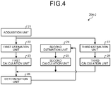
FIG. 4 is a diagram illustrating an example of the functional configuration of a processing unit in an estimation device in a second arrangement; -
FIG. 5 is a flowchart illustrating an example of an estimation method in the second arrangement; -
FIG. 6 is a diagram illustrating an example of the functional configuration of a processing unit in the estimation device in a third arrangement; -
FIG. 7 is a flowchart illustrating an example of an estimation method in the third arrangement; and -
FIG. 8 is a diagram illustrating an example of the hardware configuration of the estimation device in the first to third arrangements. - The estimation device, an estimation method, and a computer program product according to arrangements will be described below with reference to the accompanying drawings.
- An estimation device in a first arrangement is mounted on, for example, a movable body.
-
FIG. 1 is a diagram illustrating an example of amovable body 10 in the first arrangement. - The
movable body 10 includes anestimation device 20, anoutput unit 10A, acamera 10B, asensor 10C, apower control unit 10G, and apower unit 10H. - The
movable body 10 may be any movable body. Examples of themovable body 10 include a vehicle, a carriage, and a movable robot. Examples of the vehicle include a motorcycle, an automobile, and a bicycle. Themovable body 10 may be, for example, a movable body running through a human driving operation or may be a movable body capable of automatically driving (autonomous driving) without a human driving operation. - The
estimation device 20 is implemented, for example, by dedicated or general-purpose computer hardware. Theestimation device 20 estimates the location indicating at least one of the position and the pose of themovable body 10. Specifically, theestimation device 20 calculates the reliability for each of the self-location estimation results obtained by different methods and compares the reliability with a preset threshold to select or integrate the self-location estimation results. This configuration can eliminate the interruption in tracking of themovable body 10. - The
estimation device 20 is not necessarily mounted on themovable body 10. Theestimation device 20 may be mounted on a stationary object. The stationary object is, for example, an object unable to move, such as an object fixed to the ground. Examples of the stationary object fixed to the ground include a guard rail, a pole, a parked vehicle, and a road sign. For example, the stationary object is an object stationary relative to the ground. Theestimation device 20 may be installed in a cloud server that executes processing on a cloud system. - The
power unit 10H is a drive device mounted on themovable body 10. Examples of thepower unit 10H include an engine, a motor, and a wheel. - The
power control unit 10G controls thepower unit 10H. Thepower unit 10H is driven under the control of thepower control unit 10G. - The
output unit 10A outputs information. In the first arrangement, theoutput unit 10A outputs estimation result information indicating the estimation result of motion of thecamera 10B estimated by theestimation device 20. - The
output unit 10A includes, for example, a communication function of transmitting estimation result information, a display function of displaying estimation result information, and a sound output function of outputting sound indicating estimation result information. Theoutput unit 10A includes, for example, at least one of acommunication unit 10D, adisplay 10E, and aspeaker 10F. In the first arrangement, theoutput unit 10A includes thecommunication unit 10D, thedisplay 10E, and thespeaker 10F, by way of example. - The
communication unit 10D transmits estimation result information to another device. For example, thecommunication unit 10D transmits estimation result information to another device through a communication line. Thedisplay 10E displays information on the estimation result. Examples of thedisplay 10E include a liquid crystal display (LCD), a projector, and a light. Thespeaker 10F outputs sound indicating information on the estimation result. - Examples of the
camera 10B include a monocular camera, a stereo camera, a fisheye camera, and an infrared camera. Any number ofcameras 10B may be provided. The image taken may be a color image composed of three channels R, G, and B or may be a monochrome image of one channel represented by gray scales. Thecamera 10B captures time-series images of the neighborhood of themovable body 10. Thecamera 10B captures time-series images, for example, by capturing images of the neighborhood of themovable body 10 in time series. The neighborhood of themovable body 10 is, for example, a region in a predetermined range from themovable body 10. This range is, for example, a range that can be imaged by thecamera 10B. - In the first arrangement, the
camera 10B is mounted such that the front of themovable body 10 is included as the imaging direction. That is, in the first arrangement, thecamera 10B captures images of the front of themovable body 10 in time series. - The
sensor 10C is a sensor that measures measurement information. Examples of the measurement information include the speed of themovable body 10 and the steering angle of the steering wheel of themovable body 10. Examples of thesensor 10C include an inertial measurement unit (IMU), a speed sensor, and a steering angle sensor. The IMU measures measurement information including three-axis acceleration and three-axis angular velocity of themovable body 10. The speed sensor measures the speed from the amount of rotation of a tire. The steering angle sensor measures the steering angle of the steering wheel of themovable body 10. - An example of the functional configuration of the
movable body 10 in the first arrangement will now be described in detail. -
FIG. 2 is a diagram illustrating an example of the functional configuration of themovable body 10 in the first arrangement. - The
movable body 10 includes anestimation device 20, anoutput unit 10A, acamera 10B, asensor 10C, apower control unit 10G, and apower unit 10H. Theestimation device 20 includes aprocessing unit 20A and astorage unit 20B. Theoutput unit 10A includes acommunication unit 10D, adisplay 10E, and aspeaker 10F. - The
processing unit 20A, thestorage unit 20B, theoutput unit 10A, thecamera 10B, thesensor 10C, and thepower control unit 10G are connected through a bus 10I. Thepower unit 10H is connected to thepower control unit 10G. - The
output unit 10A (thecommunication unit 10D, thedisplay 10E, and thespeaker 10F), thecamera 10B, thesensor 10C, thepower control unit 10G, and thestorage unit 20B may be connected through a network. The communication system of the network used for the connection may be wired or may be wireless. The network used for the connection may be implemented by a combination of a wired system and a wireless system. - The
storage unit 20B stores information. Examples of thestorage unit 20B include a semiconductor memory device, a hard disk, and an optical disc. Examples of the semiconductor memory device include a random access memory (RAM) and a flash memory. Thestorage unit 20B may be a storage device provided on the outside of theestimation device 20. Thestorage unit 20B may be a storage medium. Specifically, the storage medium may store or temporarily store a computer program and a variety of information downloaded through a local area network (LAN) or the Internet. Thestorage unit 20B may be configured with a plurality of storage media. - The
processing unit 20A includes anacquisition unit 21, afirst estimation unit 22, afirst calculation unit 23, asecond estimation unit 24, asecond calculation unit 25, and adetermination unit 26. Theacquisition unit 21, thefirst estimation unit 22, thefirst calculation unit 23, thesecond estimation unit 24, thesecond calculation unit 25, and thedetermination unit 26 are implemented, for example, by one or more processors. - For example, the
processing unit 20A may be implemented by allowing a processor such as a central processing unit (CPU) to execute a computer program, that is, by software. For example, theprocessing unit 20A may be implemented by a processor such as a dedicated integrated circuit (IC), that is, by hardware. For example, theprocessing unit 20A may be implemented by software and hardware in combination. - The term "processor" used in the present arrangement includes CPU, graphical processing unit (GPU), application specific integrated circuit (ASIC), and programmable logic device. Examples of the programmable logic device include simple programmable logic device (SPLD), complex programmable logic device (CPLD), and field programmable gate array (FPGA).
- The processor reads and executes a computer program stored in the
storage unit 20B to implement theprocessing unit 20A. A computer program may be directly built in a circuit of the processor, rather than storing a computer program in thestorage unit 20B. In this case, the processor reads and executes the computer program built in the circuit to implement theprocessing unit 20A. - The functions of the
processing unit 20A will now be described. Theacquisition unit 21 acquires an image captured by thecamera 10B. - When accepting an image from the
acquisition unit 21, thefirst estimation unit 22 estimates at least one of the position and the pose of thecamera 10B from the image and outputs the estimated at least one of the position and the pose as first estimation information. - The
first calculation unit 23 calculates first reliability indicating the reliability of the first estimation information. - The
second estimation unit 24 estimates at least one of the position and the pose of thecamera 10B based on the past determination process result by thedetermination unit 26 and outputs the estimated at least one of the position and the pose as second estimation information. For example, thesecond estimation unit 24 performs estimation by applying Kalman filtering to the past determination process result output by thedetermination unit 26 and performing linear interpolation of the position and pose of thecamera 10B at present. - The
second calculation unit 25 calculates second reliability indicating the reliability of the second estimation information. - The
determination unit 26 decides at least one of the position and the pose of thecamera 10B from the first estimation information and the second estimation information, based on the first reliability and the second reliability, and outputs the decided at least one of the position and the pose as a determination process result. -
FIG. 3 is a flowchart illustrating an example of the estimation method in the first arrangement. Although in the description ofFIG. 3 theestimation device 20 estimates both of the position and the pose of thecamera 10B, theestimation device 20 may estimate one of the position and the pose of thecamera 10B. That is, theestimation device 20 may estimate at least one of the position and the pose of thecamera 10B. This is applicable to the second and third arrangements described later. - First, the
acquisition unit 21 acquires an image captured by at least one ormore cameras 10B (step S101). - Next, the
first estimation unit 22 estimates the first estimation information using the image captured by the process at step S101 (step S102). - Specifically, the
first estimation unit 22 extracts a plurality of feature points from images and performs matching between the images to estimate the position and the pose of thecamera 10B at the time when each image is captured. Specifically, the position and the pose of thecamera 10B at the time when each image is captured can be estimated by applying Structure from Motion (SfM) from a plurality of images obtained from thecamera 10B mounted on themovable body 10. - Alternatively, for example, the
first estimation unit 22 may apply Simultaneous Self-location and Mapping (SLAM) to an image acquired by thecamera 10B to estimate the position and the pose of thecamera 10B at the time when the image is captured. Specifically, the position and the pose can be calculated based on elementary matrices, fundamental matrices, or homography matrices, using a plurality of sets of camera coordinates of feature points. A plurality of feature point sets can be obtained by performing matching of the feature points between the images. The matching can be implemented by, for example, template matching, the Lucas-Kanade method, and SIFT. In this case, in order to obtain the absolute scale, for example, a process of normalizing the norm of a translation vector to 1 may be performed, or the scale may be determined by an acceleration sensor or a gyro sensor. - Any method may be used for representation of the position and the pose of the
camera 10B. The position and the pose of thecamera 10B may be represented, for example, by a combination of quaternions representing the coordinates and rotation in a three-dimensional space. When it can be assumed that a movement is made on a plane, for example, movement on the floor, the position and the pose can be represented by three degrees of freedom, that is, two degrees of freedom for translation and one degree of freedom for rotation. For example, rotation matrices, vectors representing the rotation of axis and the rotation direction, and Euler angles may be used for representing the pose in a three-dimensional space, instead of the quaternions. - A method of estimation without feature points may be used as another method of estimating the camera pose. As a specific method, for example, camera pose estimation by a deep learning model having a network for estimating the depth from an input image and a network for estimating a camera pose may be used.
- Next, the
first calculation unit 23 calculates the first reliability (step S103). - The method of calculating the first reliability can be implemented, for example, by the quaternions that represent the rotation components of the estimated pose of the
camera 10B by four components. In this case, it may be defined that the reliability is high if the value of qw (= cos^2(θ2) or 1-qw of the rotation components is large. - Translation may be used that represents the translation components of the estimated pose of the
camera 10B by three variables. This case focuses on the movement in two dimensions for the x direction and the z direction in the global coordinate system, and it may be defined that the first reliability is high if the coefficient in the first term of an expression of n degrees fitted based on the amount of movement is large. - Next, the
determination unit 26 determines whether the past determination process result by thedetermination unit 26 exists (step S104). - If the past determination process result does not exist (No at step S104), the
determination unit 26 decides the position and the pose of thecamera 10B directly from the image acquired by the process at step S101 (step S105). The position and the pose of thecamera 10B may be decided, for example, by a method equivalent to the process by the first estimation unit 22 (the process at step S102) or using a method differing from the process by thefirst estimation unit 22. For example, when the same method as the process by the first estimation unit 22 (the process at step S102) is used, thedetermination unit 26 decides the final position and pose of thecamera 10B by using the first estimation information. - If the past determination process result exists (Yes at step S104), the
second estimation unit 24 estimates the second estimation information using the past determination process result by the determination unit 26 (step S106). Specifically, thesecond estimation unit 24 estimates the position and the pose at present by filtering using the position and the pose included in the past determination process result as inputs. For example, Kalman filtering may be used as the filtering. Thesecond estimation unit 24 may apply Kalman filtering to the past determination process result (for example, when the position and the pose of thecamera 10B up to the previous frame estimated by thefirst estimation unit 22 are selected by thedetermination unit 26, such position and pose) and calculate the position and the pose of the camera for the present frame by linear interpolation. - Next, the
second calculation unit 25 calculates the second reliability (step S107). - The method of calculating the second reliability can be implemented, for example, using the quaternions that represent the rotation components of the estimated camera pose by four components. In this case, it may be defined that the reliability is high if the value of qw (= cos^2(θ/2) or 1-qw of the rotation components is large. Translation may be used that represents the translation components of the estimated camera pose by three variables. In this case, it may be defined that the reliability is high if the first term in the approximation expression of
degree 2 obtained from the amounts of movement of Tx and Tz is large. - Next, the
determination unit 26 decides the position and the pose of thecamera 10B from the first estimation information and the second estimation information, based on the first reliability and the second reliability (step S108). Specifically, thedetermination unit 26 may determine either estimation information as the determination process result (final output result), based on the first reliability and the second reliability. For example, when estimation is performed in the first estimation unit 102 and the first reliability is larger than a threshold (first threshold), thedetermination unit 26 may determine the first estimation information as the final output result. For example, when the first reliability is equal to or smaller than a threshold, thedetermination unit 26 may refer to the second reliability and, if the second reliability is larger than a threshold (second threshold), may determine the second estimation information as the final output result. For example, when the first reliability is equal to or smaller than a threshold and the second reliability is equal to or smaller than a threshold, thedetermination unit 26 outputs no determination process result. - For example, when the first reliability is larger than a threshold and the second reliability is larger than a threshold, the
determination unit 26 decides the position and the pose of thecamera 10B by a new position and pose obtained by integrating the first estimation information and the second estimation information and outputs the decided position and pose as a determination process result. - A specific method of integrating the first estimation information and the second estimation information is described. For example, the
determination unit 26 integrates a translation component of thecamera 10B included in the first estimation information and a translation component of thecamera 10B included in the second estimation information by the weighted mean based on the first reliability and the second reliability. For example, thedetermination unit 26 integrates a rotation component of thecamera 10B included in the first estimation information and a rotation component of thecamera 10B included in the second estimation information by spherical linear interpolation based on the first reliability and the second reliability. - The threshold for reliability (determination threshold) can be set as desired by the user and may be a constant represented by the floating-point system, for example, such as 0.9997. The same threshold may be set for the first reliability and the second reliability or different thresholds may be set. For example, when the first reliability is used as the main estimation method, a lower threshold may be set for the first reliability. When the first reliability does not exceed the threshold, the threshold for the second reliability may be set to 0 such that the estimation information by the second estimation unit is always employed as the output result.
- As described above, in the
estimation device 20 in the first arrangement, theacquisition unit 21 acquires an image captured by thecamera 10B. Thefirst estimation unit 22 estimates first estimation information indicating at least one of the position and the pose of thecamera 10B from the image. Thefirst calculation unit 23 calculates first reliability indicating the reliability of the first estimation information. Thesecond estimation unit 24 estimates second estimation information indicating at least one of the position and the pose of thecamera 10B. The second calculation unit calculates second reliability indicating the reliability of the second estimation information. Thedetermination unit 26 decides at least one of the position and the pose of thecamera 10B from the first estimation information and the second estimation information, based on the first reliability and the second reliability, and outputs the decided at least one of the position and the pose as a determination process result. Thesecond estimation unit 24 estimates second estimation information based on the past determination process result by thedetermination unit 26. - With this configuration, the
estimation device 20 in the first arrangement can estimate the location without interrupting the movement trajectory, without using a sensor other than thecamera 10B. For example, the location of themovable body 10 equipped with thecamera 10B can be estimated without interruption in the movement trajectory. - A second arrangement will now be described. In a description of the second arrangement, a description similar to the first arrangement is omitted and the points differing from the first arrangement will be described. In the second arrangement, the position and the pose of the
camera 10B that captures an image are estimated from the image by two different methods. -
FIG. 4 is a diagram illustrating an example of the functional configuration of aprocessing unit 20A-2 in theestimation device 20 in the second arrangement. Theprocessing unit 20A-2 includes anacquisition unit 21, afirst estimation unit 22, afirst calculation unit 23, asecond estimation unit 24, asecond calculation unit 25, adetermination unit 26, athird estimation unit 27, and athird calculation unit 28. That is, in the second arrangement, thethird estimation unit 27 and thethird calculation unit 28 are added to the configuration of the first arrangement. - When accepting an image from the
acquisition unit 21, thethird estimation unit 27 estimates the position and the pose of thecamera 10B from the image by a method differing from thefirst estimation unit 22 and outputs the estimated position and pose as third estimation information. For example, when thefirst estimation unit 22 applies SfM to a plurality of images to estimate the position and the pose of thecamera 10B at the time when each image is captured, thethird estimation unit 27 applies SLAM to an image to estimate the position and the pose of thecamera 10B at the time when the image is captured. - The
third calculation unit 28 calculates third reliability indicating the reliability of the third estimation information. - The
determination unit 26 decides the position and the pose of thecamera 10B from the first estimation information, the second estimation information, and the third estimation information, based on the first reliability, the second reliability, and the third reliability. The first to third reliability (or the first to third reliabilities are) is calculated based on at least one of the value of a rotation component of the pose of thecamera 10B and the amount of movement of a translation component of thecamera 10B. -
FIG. 5 is a flowchart illustrating an example of the estimation method in the second arrangement. - The processes at step S201 to step S203 are similar to the processes at step S101 to step S103 in the first arrangement and will not be further elaborated.
- The
third estimation unit 27 uses the image captured by the process at step S201 and estimates the position and the pose of thecamera 10B by a method differing from thefirst estimation unit 22 to estimate the third estimation information (step S204). - Next, the
third calculation unit 28 calculates the third reliability (step S205). The method of calculating the third reliability is similar to the method of calculating the first reliability and will not be further elaborated. - Next, the
determination unit 26 determines whether the past determination process result by thedetermination unit 26 exists (step S206). - If the past determination process result does not exist (No at step S206), the
determination unit 26 decides the position and the pose of thecamera 10B directly from the image acquired by the process at step S201 (step S207). The position and the pose of thecamera 10B may be decided, for example, by a method equivalent to the process by the first estimation unit 22 (the process at step S202) or the process by the third estimation unit 27 (the process at step S204), or using a method differing from the process by thefirst estimation unit 22 or thethird estimation unit 27. For example, thedetermination unit 26 may compare the first reliability with the third reliability and decide the final position and pose of thecamera 10B by the process result with higher reliability. For example, when the same method as the process by the first estimation unit 22 (the process at step S202) is used, thedetermination unit 26 decides the final position and pose of thecamera 10B by using the first estimation information. - If the past determination process result exists (Yes at step S206), the
second estimation unit 24 estimates the second estimation information using the past determination process result by the determination unit 26 (step S208). - Next, the
second calculation unit 25 calculates the second reliability (step S209). - Next, the
determination unit 26 decides the position and the pose of thecamera 10B from the first estimation information, the second estimation information, and the third estimation information, based on the first reliability, the second reliability, and the third reliability (step S210). Specifically, thedetermination unit 26 may determine any one of the estimation information as the final output result, based on the first reliability, the second reliability, and the third reliability. For example, when estimation is performed in the first estimation unit 202 and the first reliability is equal to or larger than a threshold, thedetermination unit 26 may determine the first estimation information as the final output result. For example, when the first reliability is equal to or smaller than a threshold, thedetermination unit 26 may refer to the third reliability and, if the third reliability is equal to or larger than a threshold, may determine the third estimation information as the final output result. For example, when the third reliability is also equal to or smaller than a threshold, thedetermination unit 26 may determine the second estimation information as the final output result. - For example, as another integrating method, the
determination unit 26 may integrate the respective estimation information based on the first reliability and the third reliability and determine a new position and pose of thecamera 10B as the final output result. Specifically, for the translation components represented by three variables, thedetermination unit 26 may calculate new translation components by the linear weighted mean using the first estimation information and the third estimation information. For the rotation components represented by four components by quaternions, thedetermination unit 26 may focus on θ, which is the common term in four variables of the rotation components, and calculate new rotation components by spherical linear interpolation (SLERP). - The threshold for reliability can be set as desired by the user and may be a constant represented by the floating-point system, for example, such as 0.9997. The same threshold may be set for the first reliability, the second reliability, and the third reliability, or different thresholds may be set. For example, when the first reliability and the third reliability are used as the main estimation method, lower thresholds may be set for the first reliability and the third reliability. When the first reliability and the third reliability do not exceed the threshold, the threshold for the second reliability may be set to 0 such that the estimation information by the second estimation unit is always employed as the output result.
- As described above, the
estimation device 20 in the second arrangement can estimate the position and the pose of themovable body 10, and further based on the third estimation information having the third reliability. - A third arrangement will now be described. In a description of the third arrangement, a description similar to the second arrangement is omitted, and the points differing from the second arrangement will be described. In the third arrangement, control of saving or discarding the position and the pose of the
camera 10B determined by thedetermination unit 26 is described. -
FIG. 6 is a diagram illustrating an example of the functional configuration of aprocessing unit 20A-3 in theestimation device 20 in the third arrangement. Theprocessing unit 20A-3 includes anacquisition unit 21, afirst estimation unit 22, afirst calculation unit 23, asecond estimation unit 24, asecond calculation unit 25, adetermination unit 26, athird estimation unit 27, athird calculation unit 28, and astorage control unit 29. That is, in the third arrangement, thestorage control unit 29 is added to the configuration of the second arrangement. - The
storage control unit 29 stores the estimation result including time-series information at the time of image capturing and the determination process result into thestorage unit 20B. The time-series information at the time of image capturing is, for example, the number that identifies an image (for example, frame number). The determination process result includes the most-recent position and pose of thecamera 10B decided by thedetermination unit 26. - When all of the first to third reliability is equal to or smaller than a threshold and an interval for which the position and the pose of the
camera 10B are not output does not exceed an estimatable interval, thestorage control unit 29 discards the above-noted estimation result. The detail of storage control by thestorage control unit 29 and the estimatable interval will be described later with reference to the flowchart inFIG. 7 . -
FIG. 7 is a flowchart illustrating an example of the estimation method in the third arrangement. - The processes at step S301 to step S310 are the same as the processes at step S201 to step S210 in the first arrangement and will not be further elaborated.
- The
storage control unit 29 determines whether all of the first to third reliability is equal to or smaller than a threshold (step S311). - If all of the first to third reliability is not equal to or smaller than a threshold (No at step S311), the
storage control unit 29 stores the estimation result including the position and pose decided by the process at step S310, the time-series information at the time of image capturing, and the integration determination process result into thestorage unit 20B (step S312). - If all of the first to third reliability is equal to or smaller than a threshold (Yes at step S311), the
storage control unit 29 determines whether within the estimatable interval of the position and the pose of thecamera 10B (the valid interval for which the previously stored determination process result is valid) (step S313). - The estimatable interval is a length of time series in which the
estimation device 20 can estimate the position and the pose of thecamera 10B. The length of time series may be represented, for example, by the number of frames of images or may be the time (timestamp) corresponding to a frame number. That is, when the interval since the estimation information is saved last time does not exceed this estimatable interval (Yes at step S313), thestorage control unit 29 discards the estimation result (step S314). When the estimatable interval is exceeded (No at step S313), the estimation result is stored into thestorage unit 20B (step S312) . - Specifically, for example, when the estimation result is stored into the
storage unit 20B in the nth frame after thestorage control unit 29 starts estimation, and the estimatable interval of theestimation device 20 is five frames, the estimation result can be discarded from the (n+1)th to (n+4)th frames. - On the other hand, if the position and the pose of the
camera 10B saved up to n+5 frames are not updated, thestorage control unit 29 stores the estimation result (the position and the pose of thecamera 10B) into thestorage unit 20B, irrespective of the reliability. The position and the pose of thecamera 10B in this case may be any one of the position and the pose of thecamera 10B estimated by thefirst estimation unit 22, thesecond estimation unit 24, and thethird estimation unit 27 or may be a new position and pose obtained by integrating the respective position and pose results. - As described above, in the
estimation device 20 in the third arrangement, when any of the first to third reliability is larger than a determination threshold, thestorage control unit 29 stores the determination process result. When all of the first to third reliability is equal to or smaller than a determination threshold and an interval for which the position and the pose of thecamera 10B are not updated is within a valid interval for which the previously stored determination process result is valid, thestorage control unit 29 discards the determination process result determined this time. When all of the first to third reliability is equal to or smaller than a determination threshold and an interval for which the position and the pose of thecamera 10B are not updated exceeds the valid interval, thestorage control unit 29 stores the determination process result determined this time. - With this configuration, the
estimation device 20 in the third arrangement can estimate the location of the movable body 10 (at least one of the position and the pose) without interrupting the movement trajectory, without using a sensor other than thecamera 10B. - Lastly, an example of the hardware configuration of the
estimation device 20 in the first to third arrangements is described. - FIG. 9 is a diagram illustrating an example of the hardware configuration of the
estimation device 20 in the first to third arrangements. Theestimation device 20 includes acontrol device 301, amain storage device 302, anauxiliary storage device 303, adisplay device 304, aninput device 305, and acommunication device 306. Thecontrol device 301, themain storage device 302, theauxiliary storage device 303, thedisplay device 304, theinput device 305, and thecommunication device 306 are connected through abus 310. - The
display device 304, theinput device 305, and thecommunication device 306 are not necessarily included. For example, when theestimation device 20 is connected to another device, the display function, the input function, and the communication function of the other device may be used. - The
control device 301 executes a computer program loaded from theauxiliary storage device 303 to themain storage device 302. Thecontrol device 301 is, for example, one or more processors such as CPU. Themain storage device 302 is a memory such as read only memory (ROM) and RAM. Examples of theauxiliary storage device 303 include a memory card and a hard disk drive (HDD). - The
display device 304 displays information. Thedisplay device 304 is, for example, a liquid crystal display. Theinput device 305 accepts input of information. Theinput device 305 is, for example, a hardware key. Thedisplay device 304 and theinput device 305 may be a liquid crystal touch panel serving as the display function and the input function. Thecommunication device 306 communicates with other devices. - The computer program executed in the
estimation device 20 is stored in a computer-readable recording medium such as a CD-ROM, a memory card, a CD-R, and a digital versatile disc (DVD) in an installable or executable file format and provided as a computer program product. - The computer program executed in the
estimation device 20 may be stored on a computer connected to a network such as the Internet and downloaded via the network. The computer program executed by theestimation device 20 may be provided via a network such as the Internet, without downloading. - The computer program executed in the
estimation device 20 may be embedded in, for example, a ROM in advance. - The computer program executed in the
estimation device 20 has a module configuration including functions that can be implemented by a computer program, of the functions of theestimation device 20. - The functions implemented by a computer program may be loaded to the
main storage device 302 by thecontrol device 301 reading and executing the computer program from a storage medium such as theauxiliary storage device 303. That is, the functions implemented by a computer program are generated on themain storage device 302. - Some of the functions of the
estimation device 20 may be implemented by hardware such as IC. The IC is, for example, a processor that executes dedicated processing. - When the functions are implemented using a plurality of processors, each processor may implement one of the functions or may implement two or more of the functions.
- While certain arrangements have been described, these arrangements have been presented by way of example only, and are not intended to limit the scope of the inventions. Indeed, the novel arrangements described herein may be embodied in a variety of other forms.
- Example 1. An estimation device includes an acquisition unit, a first estimation unit, a first calculation unit, a second estimation unit, a second calculation unit, and a determination unit. The acquisition unit acquires an image captured by a camera. The first estimation unit estimates first estimation information from the image. The first calculation unit calculates first reliability indicating reliability of the first estimation information. The second estimation unit estimates second estimation information. The second calculation unit calculates second reliability indicating reliability of the second estimation information. The determination unit decides at least one of the position and the pose of the camera from the first estimation information and the second estimation information, based on the first reliability and the second reliability, and outputs the decided at least one of the position and the pose as a determination process result. The second estimation unit estimates the second estimation information based on a past determination process result by the determination unit.
- Example 2. In the estimation device according to example 1, the second estimation unit performs estimation by applying Kalman filtering to the past determination process result and performing linear interpolation of at least one of the position and the pose of the camera at present.
- Example 3. In the estimation device according to example 1, the determination unit determines at least one of the position and the pose of the camera by using the first estimation information when the first reliability is larger than a first threshold. The determination unit determines at least one of the position and the pose of the camera by using the second estimation information when the first reliability is equal to or smaller than the first threshold and the second reliability is larger than a second threshold. Additionally, the determination unit does not output the determination process result when the first reliability is equal to or smaller than the first threshold and the second reliability is equal to or smaller than the second threshold.
- Example 4. In the estimation device according to example 1, when the first reliability is larger than a first threshold and the second reliability is larger than a second threshold, the determination unit decides at least one of the position and the pose of the camera by at least one of new position and pose obtained by integrating the first estimation information and the second estimation information.
- Example 5. In the estimation device according to example 4, the determination unit integrates a translation component of the camera included in the first estimation information and a translation component of the camera included in the second estimation information by weighted mean based on the first reliability and the second reliability.
- Example 6. In the estimation device according to example 4, the determination unit integrates a rotation component of the camera included in the first estimation information and a rotation component of the camera included in the second estimation information by spherical linear interpolation based on the first reliability and the second reliability.
- Example 7. The estimation device according to example 1 further includes a third estimation unit and a third calculation unit. The third estimation unit is configured to estimate third estimation information indicating at least one of the position and the pose of the camera from the image, using an estimation method differing from the second estimation unit. The third calculation unit is configured to calculate third reliability indicating reliability of the third estimation information. The determination unit decides at least one of the position and the pose of the camera from the first to third estimation information, and further based on the third reliability.
- Example 8. In the estimation device according to example 7, the first to third reliability is calculated based on at least one of a value of a rotation component of the pose of the camera and the amount of movement of a translation component of the camera.
- Example 9. The estimation device according to example 7, further includes a storage control unit. The storage control unit is configured to store the determination process result when any of the first to third reliability is larger than a determination threshold; and discard the determination process result determined this time when all of the first to third reliability is equal to or smaller than the determination threshold and an interval for which at least one of the position and the pose of the camera is not updated is within a valid interval for which the determination process result previously stored is valid. The storage control unit is configured to store the determination process result determined this time when all of the first to third reliability is equal to or smaller than the determination threshold and the interval
- Example 10. An estimation method is performed by a computer and includes acquiring an image captured by a camera; estimating first estimation information indicating at least one of a position and a pose of the camera from the image; calculating first reliability indicating reliability of the first estimation information; estimating second estimation information indicating at least one of the position and the pose of the camera; calculating second reliability indicating reliability of the second estimation information; and deciding at least one of the position and the pose of the camera from the first estimation information and the second estimation information, based on the first reliability and the second reliability, and outputting the decided at least one of the position and the pose as a determination process result. The estimating of the second estimation information is performed based on a past determination process result at the deciding.
- Example 11. A computer program product has a computer readable medium including programmed instructions, where the instructions, when executed by a computer, cause the computer to perform acquiring an image captured by a camera; estimating first estimation information indicating at least one of a position and a pose of the camera from the image; calculating first reliability indicating reliability of the first estimation information; estimating second estimation information indicating at least one of the position and the pose of the camera; calculating second reliability indicating reliability of the second estimation information; and deciding at least one of the position and the pose of the camera from the first estimation information and the second estimation information, based on the first reliability and the second reliability, and outputting the decided at least one of the position and the pose as a determination process result. The estimating of the second estimation information is performed based on a past determination process result at the deciding.
Claims (11)
- An estimation device (20) comprising:an acquisition unit (21) configured to acquire an image captured by a camera;a first estimation unit (22) configured to estimate first estimation information indicating at least one of a position and a pose of the camera from the image;a first calculation unit (23) configured to calculate first reliability indicating reliability of the first estimation information;a second estimation unit (24) configured to estimate second estimation information indicating at least one of the position and the pose of the camera;a second calculation unit (25) configured to calculate second reliability indicating reliability of the second estimation information; anda determination unit (26) configured to decide at least one of the position and the pose of the camera from the first estimation information and the second estimation information, based on the first reliability and the second reliability, and output the decided at least one of the position and the pose as a determination process result, whereinthe second estimation unit (24) estimates the second estimation information based on a past determination process result by the determination unit (26).
- The estimation device (20) according to claim 1, wherein the second estimation unit (24) performs estimation by applying Kalman filtering to the past determination process result and performing linear interpolation of at least one of the position and the pose of the camera at present.
- The estimation device (20) according to claim 1, wherein
the determination unit (26)
determines at least one of the position and the pose of the camera by using the first estimation information when the first reliability is larger than a first threshold,
determines at least one of the position and the pose of the camera by using the second estimation information when the first reliability is equal to or smaller than the first threshold and the second reliability is larger than a second threshold, and
does not output the determination process result when the first reliability is equal to or smaller than the first threshold and the second reliability is equal to or smaller than the second threshold. - The estimation device (20) according to claim 1, wherein when the first reliability is larger than a first threshold and the second reliability is larger than a second threshold, the determination unit (26) decides at least one of the position and the pose of the camera by at least one of new position and pose obtained by integrating the first estimation information and the second estimation information.
- The estimation device (20) according to claim 4, wherein the determination unit (26) integrates a translation component of the camera included in the first estimation information and a translation component of the camera included in the second estimation information by weighted mean based on the first reliability and the second reliability.
- The estimation device (20) according to claim 4, wherein the determination unit (26) integrates a rotation component of the camera included in the first estimation information and a rotation component of the camera included in the second estimation information by spherical linear interpolation based on the first reliability and the second reliability.
- The estimation device (20) according to claim 1, further comprising:a third estimation unit (27) configured to estimate third estimation information indicating at least one of the position and the pose of the camera from the image, using an estimation method differing from the second estimation unit (24); anda third calculation unit (28) configured to calculate third reliability indicating reliability of the third estimation information, whereinthe determination unit (26) decides at least one of the position and the pose of the camera from the first to third estimation information, and further based on the third reliability.
- The estimation device (20) according to claim 7, wherein the first to third reliability is calculated based on at least one of a value of a rotation component of the pose of the camera and the amount of movement of a translation component of the camera.
- The estimation device (20) according to claim 7, further comprising a storage control unit (20B) configured to:store the determination process result when any of the first to third reliability is larger than a determination threshold;discard the determination process result determined this time when all of the first to third reliability is equal to or smaller than the determination threshold and an interval for which at least one of the position and the pose of the camera is not updated is within a valid interval for which the determination process result previously stored is valid; andstore the determination process result determined this time when all of the first to third reliability is equal to or smaller than the determination threshold and the interval for which at least one of the position and the pose of the camera is not updated exceeds the valid interval.
- An estimation method performed by a computer and comprising:acquiring an image captured by a camera;estimating first estimation information indicating at least one of a position and a pose of the camera from the image;calculating first reliability indicating reliability of the first estimation information;estimating second estimation information indicating at least one of the position and the pose of the camera;calculating second reliability indicating reliability of the second estimation information; anddeciding at least one of the position and the pose of the camera from the first estimation information and the second estimation information, based on the first reliability and the second reliability, and outputting the decided at least one of the position and the pose as a determination process result, whereinthe estimating of the second estimation information is performed based on a past determination process result at the deciding.
- A computer program product having a computer readable medium including programmed instructions, wherein the instructions, when executed by a computer, cause the computer to perform:acquiring an image captured by a camera;estimating first estimation information indicating at least one of a position and a pose of the camera from the image;calculating first reliability indicating reliability of the first estimation information;estimating second estimation information indicating at least one of the position and the pose of the camera;calculating second reliability indicating reliability of the second estimation information; anddeciding at least one of the position and the pose of the camera from the first estimation information and the second estimation information, based on the first reliability and the second reliability, and outputting the decided at least one of the position and the pose as a determination process result, whereinthe estimating of the second estimation information is performed based on a past determination process result at the deciding.
Applications Claiming Priority (1)
| Application Number | Priority Date | Filing Date | Title |
|---|---|---|---|
| JP2019168062A JP7249919B2 (en) | 2019-09-17 | 2019-09-17 | Estimation device, estimation method and program |
Publications (1)
| Publication Number | Publication Date |
|---|---|
| EP3796257A1 true EP3796257A1 (en) | 2021-03-24 |
Family
ID=69571951
Family Applications (1)
| Application Number | Title | Priority Date | Filing Date |
|---|---|---|---|
| EP20156871.4A Pending EP3796257A1 (en) | 2019-09-17 | 2020-02-12 | Estimation device, estimation method, and computer program product |
Country Status (4)
| Country | Link |
|---|---|
| US (1) | US20210082140A1 (en) |
| EP (1) | EP3796257A1 (en) |
| JP (1) | JP7249919B2 (en) |
| CN (1) | CN112529932B (en) |
Families Citing this family (3)
| Publication number | Priority date | Publication date | Assignee | Title |
|---|---|---|---|---|
| EP4348174B1 (en) * | 2021-05-31 | 2025-05-14 | trinamiX GmbH | Auto calibration from epipolar line distance in projection pattern |
| JP7460867B2 (en) * | 2021-12-24 | 2024-04-03 | パナソニックオートモーティブシステムズ株式会社 | Estimation device, estimation method, and program |
| DE102022106110A1 (en) * | 2022-03-16 | 2023-09-21 | Spleenlab GmbH | Method for safely determining a flight path of an unmanned aerial vehicle and unmanned aerial vehicle |
Citations (4)
| Publication number | Priority date | Publication date | Assignee | Title |
|---|---|---|---|---|
| US9031782B1 (en) * | 2012-01-23 | 2015-05-12 | The United States Of America As Represented By The Secretary Of The Navy | System to use digital cameras and other sensors in navigation |
| EP3032496A1 (en) * | 2014-12-11 | 2016-06-15 | Megachips Corporation | State estimation apparatus, program, and integrated circuit |
| US20170132794A1 (en) * | 2015-11-05 | 2017-05-11 | Samsung Electronics Co., Ltd. | Pose estimation method and apparatus |
| US20180286056A1 (en) * | 2015-09-30 | 2018-10-04 | Sony Corporation | Information processing device, information processing method, and program |
Family Cites Families (3)
| Publication number | Priority date | Publication date | Assignee | Title |
|---|---|---|---|---|
| JP5843288B2 (en) * | 2012-04-19 | 2016-01-13 | Kddi株式会社 | Information presentation system |
| KR102472767B1 (en) * | 2017-09-14 | 2022-12-01 | 삼성전자주식회사 | Method and apparatus of calculating depth map based on reliability |
| JP7149707B2 (en) * | 2018-01-15 | 2022-10-07 | キヤノン株式会社 | Information processing device, its control method and program, and operation control system |
-
2019
- 2019-09-17 JP JP2019168062A patent/JP7249919B2/en active Active
-
2020
- 2020-02-12 EP EP20156871.4A patent/EP3796257A1/en active Pending
- 2020-02-20 US US16/795,711 patent/US20210082140A1/en not_active Abandoned
- 2020-02-26 CN CN202010118380.4A patent/CN112529932B/en active Active
Patent Citations (4)
| Publication number | Priority date | Publication date | Assignee | Title |
|---|---|---|---|---|
| US9031782B1 (en) * | 2012-01-23 | 2015-05-12 | The United States Of America As Represented By The Secretary Of The Navy | System to use digital cameras and other sensors in navigation |
| EP3032496A1 (en) * | 2014-12-11 | 2016-06-15 | Megachips Corporation | State estimation apparatus, program, and integrated circuit |
| US20180286056A1 (en) * | 2015-09-30 | 2018-10-04 | Sony Corporation | Information processing device, information processing method, and program |
| US20170132794A1 (en) * | 2015-11-05 | 2017-05-11 | Samsung Electronics Co., Ltd. | Pose estimation method and apparatus |
Non-Patent Citations (1)
| Title |
|---|
| ANDREW J DAVISON ET AL: "MonoSLAM: Real-Time Single Camera SLAM", IEEE TRANSACTIONS ON PATTERN ANALYSIS AND MACHINE INTELLIGENCE, IEEE COMPUTER SOCIETY, USA, vol. 29, no. 6, 1 June 2007 (2007-06-01), pages 1052 - 1067, XP011179664, ISSN: 0162-8828, DOI: 10.1109/TPAMI.2007.1049 * |
Also Published As
| Publication number | Publication date |
|---|---|
| US20210082140A1 (en) | 2021-03-18 |
| CN112529932A (en) | 2021-03-19 |
| JP7249919B2 (en) | 2023-03-31 |
| JP2021047479A (en) | 2021-03-25 |
| CN112529932B (en) | 2024-11-15 |
Similar Documents
| Publication | Publication Date | Title |
|---|---|---|
| EP3627180B1 (en) | Sensor calibration method and device, computer device, medium, and vehicle | |
| KR101776622B1 (en) | Apparatus for recognizing location mobile robot using edge based refinement and method thereof | |
| KR101784183B1 (en) | APPARATUS FOR RECOGNIZING LOCATION MOBILE ROBOT USING KEY POINT BASED ON ADoG AND METHOD THEREOF | |
| CN103119623B (en) | Pupil detector and pupil detection method | |
| KR101776621B1 (en) | Apparatus for recognizing location mobile robot using edge based refinement and method thereof | |
| WO2016035324A1 (en) | Method for estimating motion, mobile agent and non-transitory computer-readable medium encoded with a computer program code for causing a processor to execute a method for estimating motion | |
| US9330472B2 (en) | System and method for distorted camera image correction | |
| CN105654031B (en) | System and method for object detection | |
| US20180114067A1 (en) | Apparatus and method for extracting objects in view point of moving vehicle | |
| US20120257056A1 (en) | Image processing apparatus, image processing method, and image processing program | |
| EP3188128A1 (en) | Information-processing device, information processing method, and program | |
| KR20150144728A (en) | Apparatus for recognizing location mobile robot using search based correlative matching and method thereof | |
| CN111213153A (en) | Target object motion state detection method, device and storage medium | |
| CN112396634B (en) | Moving object detection method, moving object detection device, vehicle and storage medium | |
| US20210082140A1 (en) | Estimation device, estimation method, and computer program product | |
| JP5107154B2 (en) | Motion estimation device | |
| US20190050995A1 (en) | Camera motion estimation device, camera motion estimation method, and computer program product | |
| US11921823B2 (en) | Image processing device and image processing method | |
| EP3795952A1 (en) | Estimation device, estimation method, and computer program product | |
| JP2020076714A (en) | Position attitude estimation device | |
| JP6886136B2 (en) | Alignment device, alignment method and computer program for alignment | |
| JP2019191691A (en) | Image processing apparatus, mobile apparatus and method, and program | |
| US12112502B2 (en) | Three-dimensional map estimation apparatus and obstacle detection apparatus | |
| JP2001034388A (en) | Equipment control device and navigation device | |
| JP6488697B2 (en) | Optical flow calculation device, optical flow calculation method, and program |
Legal Events
| Date | Code | Title | Description |
|---|---|---|---|
| PUAI | Public reference made under article 153(3) epc to a published international application that has entered the european phase |
Free format text: ORIGINAL CODE: 0009012 |
|
| STAA | Information on the status of an ep patent application or granted ep patent |
Free format text: STATUS: REQUEST FOR EXAMINATION WAS MADE |
|
| 17P | Request for examination filed |
Effective date: 20200212 |
|
| AK | Designated contracting states |
Kind code of ref document: A1 Designated state(s): AL AT BE BG CH CY CZ DE DK EE ES FI FR GB GR HR HU IE IS IT LI LT LU LV MC MK MT NL NO PL PT RO RS SE SI SK SM TR |
|
| AX | Request for extension of the european patent |
Extension state: BA ME |
|
| STAA | Information on the status of an ep patent application or granted ep patent |
Free format text: STATUS: EXAMINATION IS IN PROGRESS |
|
| 17Q | First examination report despatched |
Effective date: 20230314 |
|
| GRAP | Despatch of communication of intention to grant a patent |
Free format text: ORIGINAL CODE: EPIDOSNIGR1 |
|
| STAA | Information on the status of an ep patent application or granted ep patent |
Free format text: STATUS: GRANT OF PATENT IS INTENDED |
|
| INTG | Intention to grant announced |
Effective date: 20251215 |
|
| GRAS | Grant fee paid |
Free format text: ORIGINAL CODE: EPIDOSNIGR3 |
|
| GRAA | (expected) grant |
Free format text: ORIGINAL CODE: 0009210 |
|
| STAA | Information on the status of an ep patent application or granted ep patent |
Free format text: STATUS: THE PATENT HAS BEEN GRANTED |
|
| RAP3 | Party data changed (applicant data changed or rights of an application transferred) |
Owner name: KABUSHIKI KAISHA TOSHIBA Owner name: TOSHIBA ELECTRONIC DEVICES & STORAGE CORPORATION |