EP3796207A1 - Container identification system and method, safety inspection device, and port facility - Google Patents
Container identification system and method, safety inspection device, and port facility Download PDFInfo
- Publication number
- EP3796207A1 EP3796207A1 EP20736194.0A EP20736194A EP3796207A1 EP 3796207 A1 EP3796207 A1 EP 3796207A1 EP 20736194 A EP20736194 A EP 20736194A EP 3796207 A1 EP3796207 A1 EP 3796207A1
- Authority
- EP
- European Patent Office
- Prior art keywords
- container
- identification
- capturing
- end surface
- capturing camera
- Prior art date
- Legal status (The legal status is an assumption and is not a legal conclusion. Google has not performed a legal analysis and makes no representation as to the accuracy of the status listed.)
- Pending
Links
Images



Classifications
-
- G—PHYSICS
- G06—COMPUTING OR CALCULATING; COUNTING
- G06K—GRAPHICAL DATA READING; PRESENTATION OF DATA; RECORD CARRIERS; HANDLING RECORD CARRIERS
- G06K7/00—Methods or arrangements for sensing record carriers, e.g. for reading patterns
- G06K7/10—Methods or arrangements for sensing record carriers, e.g. for reading patterns by electromagnetic radiation, e.g. optical sensing; by corpuscular radiation
- G06K7/10544—Methods or arrangements for sensing record carriers, e.g. for reading patterns by electromagnetic radiation, e.g. optical sensing; by corpuscular radiation by scanning of the records by radiation in the optical part of the electromagnetic spectrum
- G06K7/10712—Fixed beam scanning
- G06K7/10722—Photodetector array or CCD scanning
-
- G—PHYSICS
- G06—COMPUTING OR CALCULATING; COUNTING
- G06K—GRAPHICAL DATA READING; PRESENTATION OF DATA; RECORD CARRIERS; HANDLING RECORD CARRIERS
- G06K7/00—Methods or arrangements for sensing record carriers, e.g. for reading patterns
- G06K7/10—Methods or arrangements for sensing record carriers, e.g. for reading patterns by electromagnetic radiation, e.g. optical sensing; by corpuscular radiation
- G06K7/10544—Methods or arrangements for sensing record carriers, e.g. for reading patterns by electromagnetic radiation, e.g. optical sensing; by corpuscular radiation by scanning of the records by radiation in the optical part of the electromagnetic spectrum
- G06K7/10712—Fixed beam scanning
- G06K7/10762—Relative movement
-
- G—PHYSICS
- G06—COMPUTING OR CALCULATING; COUNTING
- G06K—GRAPHICAL DATA READING; PRESENTATION OF DATA; RECORD CARRIERS; HANDLING RECORD CARRIERS
- G06K7/00—Methods or arrangements for sensing record carriers, e.g. for reading patterns
- G06K7/10—Methods or arrangements for sensing record carriers, e.g. for reading patterns by electromagnetic radiation, e.g. optical sensing; by corpuscular radiation
- G06K7/10544—Methods or arrangements for sensing record carriers, e.g. for reading patterns by electromagnetic radiation, e.g. optical sensing; by corpuscular radiation by scanning of the records by radiation in the optical part of the electromagnetic spectrum
- G06K7/10821—Methods or arrangements for sensing record carriers, e.g. for reading patterns by electromagnetic radiation, e.g. optical sensing; by corpuscular radiation by scanning of the records by radiation in the optical part of the electromagnetic spectrum further details of bar or optical code scanning devices
-
- G—PHYSICS
- G06—COMPUTING OR CALCULATING; COUNTING
- G06V—IMAGE OR VIDEO RECOGNITION OR UNDERSTANDING
- G06V20/00—Scenes; Scene-specific elements
- G06V20/10—Terrestrial scenes
-
- G—PHYSICS
- G06—COMPUTING OR CALCULATING; COUNTING
- G06V—IMAGE OR VIDEO RECOGNITION OR UNDERSTANDING
- G06V20/00—Scenes; Scene-specific elements
- G06V20/50—Context or environment of the image
- G06V20/52—Surveillance or monitoring of activities, e.g. for recognising suspicious objects
Definitions
- the present disclosure relates to the technical field of device detection, and in particular, to a container identification system, an identification method, a safety inspection device, and a port facility.
- containers are widely used in logistics transportation.
- container numbers may be provided for the containers.
- RFID radio frequency identification
- a plurality of uprights and crossbars are fixed at a measurement site to install a plurality of detection components for identifying the container number on different sides of the container (e.g. sensors such as cameras and photoelectric switches).
- a container identification system includes:
- the door frame includes a cross beam and two longitudinal beams which are connected on both ends of the cross beam respectively, the area laser scanner is arranged on one of the longitudinal beams, and a laser irradiation surface of the area laser scanner faces towards the passage.
- the area laser scanner is configured to identify a front end surface of the container along a movement direction.
- the identification obtaining apparatus includes a plurality of capturing cameras, which are disposed at different positions on the door frame to capture identifications on different surfaces of the container respectively.
- the container identification system further including a controller, wherein the area laser scanner is configured to detect a distance between the capturing camera and an end surface of the container so as to determine the current position of the container, and the controller is configured to determine a timing when the plurality of capturing cameras are enabled according to the distance between the capturing camera and the end surface of the container.
- the area laser scanner is configured to detect a distance between the capturing camera and a front end surface
- the controller is configured to determine a timing when the capturing cameras are enabled for capturing the front end surface, a first side, and a front area of a top surface of the container according to the distance between the capturing camera and the front end surface, wherein an identification on the first side is disposed proximate to the front end surface;
- the area laser scanner is configured to detect a distance between the capturing camera and a rear end surface
- the controller is configured to determine a timing when the capturing cameras are enabled for capturing the rear end surface, a second side and a rear area of a top surface of the container according to the distance between the capturing camera and the rear end surface, wherein an identification on the second side is disposed proximate to the rear end surface.
- only one of the capturing cameras is in an enabled state at the same moment.
- the door frame includes a cross beam and two longitudinal beams which are connected on both ends of the cross beam respectively, and the plurality of capturing cameras are disposed on the cross beam and the longitudinal beams.
- the plurality of the capturing cameras are arranged at intervals along at least one of a length direction and a width direction of the cross beam according to positions where identifications are provided on different surfaces of the container.
- the plurality of capturing cameras have different capturing directions, the number of the capturing cameras is the same as that of the surfaces of the container on which identifications are provided, and the plurality of capturing cameras are configured to obtain identifications on different surfaces of the container.
- the container identification system further including a controller configured to receive identifications obtained by the plurality of capturing cameras, and extract identification results for voting to output a final identification result.
- the identification obtaining apparatus includes:
- the second capturing camera and the fourth capturing camera irradiate toward an inside of the door frame
- the first capturing camera, the third capturing camera and the fifth capturing camera irradiate toward an outside of the door frame, and an irradiation direction of the fifth capturing camera is inclined toward a center line of the length direction of the cross beam.
- the door frame includes a cross beam and two longitudinal beams, and at least one of the cross beam and the longitudinal beam has an adjustable length.
- the container identification system further including a base through which the area laser scanner and the identification obtaining apparatus are both mounted on the door frame, wherein the base is provided with at least one of a position adjustment mechanism and an attitude adjustment mechanism, wherein:
- an identification method based on the container identification system according to the above embodiments includes:
- the identification obtaining apparatus includes a plurality of capturing cameras respectively configured to capture identifications on different surfaces of the container, and the container identification method further includes:
- the identification obtaining apparatus includes a plurality of capturing cameras respectively configured to capture identifications on different surfaces of the container, and the step of obtaining identifications on respective sides of the container by the identification obtaining apparatus according to the current position of the container includes:
- the identification obtaining apparatus includes a plurality of capturing cameras respectively configured to capture identifications on different surfaces of the container, so that the step of obtaining identifications on respective sides of the container by the identification obtaining apparatus according to the current position of the container includes:
- the step of obtaining identifications on respective sides of the container by the identification obtaining apparatus according to the current position of the container includes:
- a safety inspection device including the container identification system according to the above embodiments, wherein the container identification system is installed on a boom of the safety inspection device; or a boom of the safety inspection device directly serves as a door frame of the container identification system.
- a port facility including at least one of the container identification system and the safety inspection device according to the above embodiments.
- first and second recited in the present disclosure are merely for ease of description, to distinguish different constituent parts having the same name, rather than indicating a sequential or primary-secondary relationship.
- the container number identification device known to the inventors has at least one of the following disadvantages: (1) when the RFID label is read, there are high requirements for label position and ambient environment, and the RFID label which needs to be continuously maintained is less cost-effective, and there is no image record, which makes it inconvenient to verify the correctness of an identification result; (2) a plurality of uprights and crossbars are fixed on the measurement site, with a large occupied area, a large number of sensors, a long debugging cycle for the sensors and a complicated layout and wiring, so that the arrangement of the components cannot even be completed at some special sites, with a restricted use. Therefore, there is a need to design a new container identification system.
- the present disclosure improves the container identification system, and provides a container identification system, an identification method, a safety inspection device and a port facility, which can reduce the installation difficulty.
- a door frame is provided with an area laser scanner and an identification obtaining apparatus.
- the area laser scanner is configured to detect a relative movement direction and a relative position of the container with the door frame.
- the identification obtaining apparatus is configured to obtain the identifications on respective sides of the container according to the position detection results of the area laser scanner.
- Such container identification system which integrates the area laser scanner and the identification obtaining apparatus on the door frame, may perform an integrated installation in a practical application, which improves the integration of the identification system, and occupies a small area, or may also be additionally installed on other door frame devices, thereby reducing the civil engineering work and the number of the installed brackets, with flexible and convenient use, and facilitating the installation and debugging, and also enhancing integrated transfer.
- the container identification system of the present disclosure is configured to identify the identification on the container 1.
- the container 1 may be a container.
- IS06346:1995 Container Code, Identification and Marking standard of International Organization for Standardization stipulates the container identification system, size and container type code, as well as related identifications and identification methods.
- the identifications stipulated in the standard include: container owner code, device identification code, container number and check code.
- the identification of the container 1 includes a group of serial numbers containing four Latin letters and seven Arabic numbers which consist of a size and a container type code A, a container number and a check code B, as well as a container owner code and a device identification code C.
- identification codes with a uniform standard, it is possible to improve the universal use of the system and facilitate obtaining the identification logic, and there is no need to make individual designs so that the cost is saved.
- the identification code may also be a two-dimensional code commonly used at present.
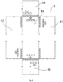
- the respective sides of the container 1 include a first side 11, a second side 12, a top surface 13, a front end surface 14, and a rear end surface 15, the rear end surface 15 is a door end, the first side 11, the second side 12, the top surface 13, the front end surface 14 and the rear end surface 15 are all marked with a size and a container code A, a container number and check code B, as well as a container owner code and a device identification code C.
- the identifications are provided at different positions.
- the present disclosure first provides a container identification system.
- the system includes: a door frame 5, an area laser scanner 2 and an identification obtaining apparatus, wherein the door frame 5 has a passage for the container 1 to be identified to pass through; the area laser scanner 2 is provided on the door frame 5 to detect a current position of the container 1; the identification obtaining apparatus is disposed on the door frame 5 to obtain the identifications on the respective sides of the container 1 according to the current position of the container 1 relative to the door frame 5.
- Such container identification system may be fixedly provided in a site, or a roller is provided at a bottom end of the door frame 5 to move on the track, or a movable wheel is provided at a bottom end of the door frame 5, or integrated in the safety inspection device, so that there is a wide application range.
- the door frame 5 includes a cross beam 51 and two longitudinal beams 52, wherein the two longitudinal beams 52 are respectively connected to both ends of the cross beam 51.
- the area laser scanner 2 is disposed on one of the longitudinal beams 52, and the laser irradiation surface faces towards the passage. Referring to Fig. 7 , the area laser scanner 2 emits a sector-shaped laser beam from the longitudinal beam 52, which may entirely cover the passage through which the container 1 passes. Alternatively, the area laser scanner 2 may be also provided on the cross beam 51.
- the area laser scanner 2 By providing the area laser scanner 2, it is possible to automatically determine the entering direction of the vehicle on which the container 1 is mounted along the passage. Regardless of the direction in which the container 1 enters the passage, it is possible to determine the type and number of the container 1 mounted on the vehicle passing through the passage, and at the same time obtain the size code and the container type code of the container 1.
- the area laser scanner 2 is configured to identify the front end surface of the container 1 along a movement direction. When the vehicle on which the container 1 is mounted approaches the door frame 5, the area laser scanner 2 can distinguish the front end surface of the vehicle from the front end surface 14 of the container 1 in order to start the identification process.
- the identification obtaining apparatus includes a plurality of capturing cameras, which are disposed at different positions on the door frame 5 to capture the identifications on different surfaces of the container 1 respectively.
- a capturing camera By using a capturing camera to obtain the identification has a low requirement for the ambient environment, which may reduce the maintenance frequency, and facilitate verifying the correctness of the identification result by image recording.
- the capturing camera is a web camera, which can directly upload the capturing result to the control system.
- the container identification system also includes a controller.
- the area laser scanner 2 is configured to detect the distance between the camera and the end surface of the container 1 so as to determine the current position of the container 1.
- the controller is configured to determine the distance between the capturing camera and the end surface of the container 1 to determine the moment when the respective capturing cameras are enabled.
- each of the capturing cameras may capture the identification on a side to be captured when a proper distance is reached, so that it is possible to improve the accuracy of the identification result.
- the area laser scanner 2 is configured to detect a distance between the capturing camera and the front end surface 14, and the controller is configured to determine a timing when the capturing cameras are enabled for capturing the front end surface 14, the first side 11 and the front area of the top surface 13 of the container 1 according to the distance between the capturing camera and the front end surface 14.
- the identification on the first side 11 is disposed proximate to the front end surface 14.
- the area laser scanner 2 is configured to detect a distance between the capturing camera and the rear end surface 15, and the controller is configured to determine a timing when the capturing cameras are enabled for capturing the rear end surface 15, the second side 12, and the rear area of the top surface 13 of the container according to the distance between the capturing camera and the rear end surface 15.
- the identification on the second side 12 is disposed proximate to the rear end surface 15. Since the identifications on the second side 12 and the rear area of the top surface 13 are closer to the rear end surface 15, the timing when the capturing cameras are enabled to identify the rear end surface 15, the second side 12, and the rear area of the top surface 13 are determined with the rear end surface 15 as a reference, which facilitates improving the accuracy of the distance detection, thereby improving the accuracy of the identification result.
- each capturing camera can identify the identification when a proper distance is reached, thereby improving the quality of the captured image, and the plurality of capturing cameras can not be interfered during operation, thereby facilitating accurately obtaining the identifications on the container.
- the container identification system further includes a plurality of fill lights, which are provided on the door frame 5 for supplementing light sources for the capturing cameras at adjacent positions so as to improve the definition of the captured image or video, thereby improving the accuracy of the identification.
- the door frame 5 includes a cross beam 51 and two longitudinal beams 52.
- the two longitudinal beams 52 are respectively connected to both ends of the cross beam 51, and the respective capturing cameras are disposed on the cross beam 51 and the longitudinal beams 52. According to the needs in different sides of the capturing container 1, the capturing cameras may be provided at different positions of the door frame 5.
- the plurality of capturing cameras are arranged at intervals along at least one of the length direction and width direction of the cross beam 51 according to the positions where the identifications are provided on different surfaces of the container 1.
- the capturing directions of the plurality of capturing cameras are different, the number of the capturing cameras is the same as that of the surfaces of the container 1 on which identifications are provided, and the plurality of capturing camera are configured to obtain the identifications on different surfaces of the container 1. In this embodiment, it is possible to reduce the number of the capturing cameras provided and reduce the cost whilst capturing the identifications on the respective sides of the container 1.
- the container identification system of the present disclosure further includes a controller for receiving the identifications obtained by the plurality of capturing cameras, and extracting identification results for voting to output a final identification result.
- a controller for receiving the identifications obtained by the plurality of capturing cameras, and extracting identification results for voting to output a final identification result.
- different capturing cameras perform identification at different moments, and the identification results of the plurality of capturing cameras are sent to the controller, which determines the final identification result in a voting manner, thereby improving the accuracy of the identification.
- the identification obtaining apparatus includes five capturing cameras, which are as follows:
- a first capturing camera 31, as shown in Fig. 3 and Fig.5 is disposed on an edge position of the cross beam 51 proximate to an entry side of the container 1, and configured to capture the identification on the front end surface 14 of the container 1 along the movement direction.
- a first fill light 41 and a second fill light 41' may be provided on the cross beam 51 on both sides of the first capturing camera 31 respectively.
- a second capturing camera 32 is disposed on a longitudinal beam 52 on an opposite side of the area laser scanner 2, and configured to capture the identification on the first side 11 of the container 1 opposite to the second capturing camera 32.
- a third fill light 42 may be provided on the longitudinal beam 52 above or below the second capturing camera 32.
- a third capturing camera 33 is disposed on an edge position of the cross beam 51 proximate to an exit side of the container 1, and located at a center position of the cross beam 51 along the length direction, for capturing the identifications on the front area and the rear area of the top surface 13 of the container 1.
- a fourth fill light 43 may be provided on the cross beam 51 outside the third capturing camera 33.
- a fourth capturing camera 34 is disposed on the longitudinal beam 52 on the same side as the area laser scanner 2, and configured to capture the identification on the second side 12 of the container 1 opposite to the fourth capturing camera 34.
- a fifth fill light 44 may be provided on the longitudinal beam 52 above or below the fourth capturing camera 34;
- a fifth capturing camera 35 is disposed on an edge position of the cross beam 51 proximate to the exit side of the container 1, and biased from the center position of the cross beam 51 along the length direction, for capturing the identification on the rear end surface 15 of the container 1 along the movement direction.
- a sixth fill light 45 may be provided on the cross beam 51 outside the fifth capturing camera 35.
- the respective capturing cameras may be arranged on the door frame 5 with a narrow size along the passage extending direction.
- Such arrangement manner may allow that the capturing of the respective capturing cameras for the respective sides of the container 1 is not affected by the size of the door frame 5 along the passage extending direction, so that it is possible to reduce the size of the door frame 5 along the passage width direction, thereby further reducing the occupied space, and realizing a lightweight design.
- the second capturing camera 32 and the fourth capturing camera 34 irradiate toward the inside of the door frame 5, and the first capturing camera 31, the third capturing camera 33, and the fifth capturing camera 35 irradiate toward the outside of the door frame 5.
- the irradiation direction of the fifth capturing camera 35 is inclined toward the center line in the length direction of the cross beam 51. The positions at which the respective capturing cameras are provided as well as the irradiation directions can align them with the identifications on the corresponding sides of the container 1.
- the cross beam 51 and the two longitudinal beams 52 may be designed to be structures with an adjustable length, so as to adapt to the container 1 of different widths and heights by adjusting the size of the passage size.
- At least one of the width and height of the passage may be increased when the size of the container 1 is large, so that the container 1 can pass smoothly and prevent damage to the area laser scanner 2 and the identification obtaining apparatus; and at least one of the width and height of the passage may be decreased when the size of the container 1 is small, so that each component is within a proper operation distance, thereby improving the accuracy of obtaining the identification information.
- the adjustable door frame 5 may also adapt to the door frame size of the safety inspection device, thereby facilitating integration with the safety inspection device.
- the area laser scanner 2 and the identification obtaining apparatus may be installed on the door frame 5 through a base on which a position adjustment mechanism and an attitude adjustment mechanism are provided.
- the position adjustment mechanism is configured to change a position where the area laser scanner 2 and/or the identification obtaining apparatus provided on the door frame 5, and the attitude adjustment mechanism is configured to change the installation an attitude of the area laser scanner 2 and/or the identification obtaining apparatus.
- the identification includes: at least one of a container owner code, a device identification code, a container number, a check code, a size, and a container type code.
- the operation principles of the container identification system of the present disclosure will be described below in conjunction with Fig. 5 to Fig. 10 .
- the arrows indicate the movement direction of the container 1 relative to the door frame 5 within the passage. Such movement that is relative neither delimits the direction of the relative movement, nor delimits that either of the automatic identification system or the identified container is in an absolutely stationary state. At the same time, the system does not delimit the size of the gap between the containers and the number of containers continuously passing through the passage when the containers pass through the identification passage.
- the area laser scanner 2 When the area laser scanner 2 detects that the container 1 moves to a preset position, the area laser scanner 2 identifies the front end surface 14 of the container 1 along the movement direction, and instructs the identification obtaining apparatus to carry out action processes such as capturing preparation and formal capturing.
- the capturing preparation actions include, but are not limited to, collection of ambient illuminance, calculation of capturing exposure parameters and gain parameters, whether to use light fill measures by lamps and the like.
- the formal capturing actions may be photographing or capturing video images.
- the area laser scanner 2 detects that the distance between the first capturing camera 31 and the front end surface 14 of the container 1 reaches a first preset value, and the first capturing camera 31 is enabled to obtain and store the identification size and the container type code A, the container number and the check code B, as well as the container owner code and the device identification code C on the front end surface 14 of the container 1.
- the area laser scanner 2 detects that the front end surface 14 of the container 1 exceeds the second preset value of the second capturing camera 32, and the second capturing camera 32 is enabled to obtain and store the identification on the first side 11 of the container 1.
- the area laser scanner 2 detects that the front end surface 14 of the container 1 goes beyond the third camera 33, and the distance between the third camera 33 and the front end surface 14 reaches a third preset value, the third capturing camera 33 is enabled to obtain and store the identification on the front area of the top surface 13 of the container 1.
- the area laser scanner 2 detects that the fourth capturing camera 34 is located in front of the rear end surface 15 and the distance reaches a fourth preset value, the fourth capturing camera 34 is enabled obtain and store the identification on the second side 12 of the container 1.
- the area laser scanner 2 detects that the container 1 leaves the door frame 5 and the distance between the third capturing camera 33 and the rear end 15 reaches a fifth preset value, the third capturing camera 33 is enabled to obtain and store the identification on the rear area of the top surface 13 of the container 1.
- the area laser scanner 2 detects that the distance between the fifth capturing camera 35 and the rear end surface 15 reaches a sixth preset value, and the fifth capturing camera 35 is enabled to obtain and store the identification on the rear end surface 15 of the container 1. After the container 1 leaves the container identification system, six identifications on the container 1 may be obtained by five capturing cameras.
- the arrow direction in the drawings is a forward direction of the movement of the container 1.
- the capturing may be performed in a completely reverse order. Regardless of whether the container pass therethrough in a forward direction or in a reverse direction, it is not limited to an entry direction of a next vehicle on which the container 1 is mounted.
- such container identification system may identify at least one of the container number, the container type, and the number of containers passing through the door frame 5.
- the present disclosure also provides an identification method based on the container identification system of the above-described embodiments.
- the method includes:
- the identification obtaining apparatus includes a plurality of capturing cameras, which are respectively configured to capture the identifications on different sides of the container 1.
- the container identification method further includes:
- the steps in this embodiment may be performed by the controller. According to the positions of the respective sides of the container 1 obtained by the laser area scanner 2, different capturing cameras perform identification at different moments, and the identification results of the respective capturing cameras are sent to the controller, which determines the final identification result in a voting manner, so as to improve the accuracy of the identification.
- the identification obtaining apparatus includes a plurality of capturing cameras, which are respectively configured to capture the identifications on different sides of the container 1.
- the step of obtaining the identifications on the respective surfaces of the container 1 by the identification obtaining apparatus according to the relative movement direction and the relative position of the container 1 and the door frame 5 includes:
- the step of obtaining the identifications on the respective surfaces of the container 1 by the identification obtaining apparatus according to the current position of the container 1 specifically includes:
- the steps (2) and (3) are interchangeable according to the front and rear positions of the identifications on the first side 11 and the front area of the top surface 13 of the container 1; and the steps (4) and (5) are interchangeable according to the front and rear positions of the identifications on the second side 12 and the rear area of the top surface 13 of the container 1.
- the present disclosure also provides a safety inspection device, as shown in Fig. 11 and Fig. 12 , including the container identification system of the above-described embodiments.
- a safety inspection device that also adds a container identification function on the basis of the inherent container interior scanning function, may enable at least one of the container identification function and the container interior scanning function as required.
- both functions are enabled at the same time, when the container 1 passes through the scanning passage of the safety inspection device, it is not only possible to inspect the conditions of goods inside the container 1 through a probe arm, but also possible to identify the identifications on the container 1 at the same time. Since the two steps are carried out simultaneously, it is possible to improve the efficiency of scanning inspections and obtaining the identifications.
- the container identification system is installed on the boom 6 of the safety inspection device, including a fixed installation and a detachable installation.
- the safety inspection device in which the container identification system is detachably installed may decide whether to add a container identification system according to user needs, or can also flexibly replace different types or specifications of container identification systems.
- the safety inspection device includes a boom 6, a first cabin 7 and a second cabin 8.
- the boom 6 is in the form of a gantry, including a transverse arm and vertical arms provided at both ends of the transverse arm. Two vertical arms are installed on the first cabin 7 and the second cabin 8 respectively.
- the container identification system is directly installed on the boom 6 of the safety inspection device through the door frame 5.
- the container identification system is installed on the safety inspection device as an independent module, which facilitates the installation. Such installation manner is suitable for the safety inspection device that uses a boom in the form of a gantry.
- the boom 6 of the safety inspection device directly serves as the door frame 5 of the container identification system. That is, the area laser scanner 2 and the identification obtaining apparatus are directly integrated on the boom 6 of the safety inspection device.
- This embodiment may simplify the structure of the boom 6 of the safety inspection device, thereby reducing the weight, and preventing deformation of the boom 6.
- the safety inspection device includes a boom 6 and a radiation source.
- the boom 6 is in the form of an L-shaped cantilever. Since the vertical arm on an installation side of the boom 6 has a short length so that it is not convenient to install the door frame 5, the boom 6 may directly serve as the door frame 5 of the container identification system so as to reduce the weight of the boom 6, and prevent deformation of the boom 6 without affecting the collapse of the boom 6.
- the area laser scanner 2 and the identification obtaining apparatus may be installed on one side of the boom 6 along the inspection passage so as not to affect the installation of the detector.
- the radiation scanning system and the container identification system may share the area laser scanner 2 for detecting a movement position of the container, and the controller is configured to enable the radiation source when the container is about to reach the boom 6, and obtain the identifications on the respective sides of the container 1 according to the current position of the container 1.
- the controller is configured to enable the radiation source when the container is about to reach the boom 6, and obtain the identifications on the respective sides of the container 1 according to the current position of the container 1.
- the safety inspection device of the present disclosure may be a stationary, track-based mobile, or traveling safety inspection device or the like.
- the present disclosure also provides a port facility including at least one of the container identification system of the above-described embodiments and the safety inspection device of the above-described embodiments.
- the container identification system may be fixed in the site, or on the track, or integrated in the safety inspection device.
- the port facility further includes a container 1, and the identifications provided on different sides of the container are the same. Generally, the positions where the identifications are provided on the respective sides of the general container are fixed.
- a plurality of identifications are arranged asymmetrically on the container, and a plurality of capturing cameras are arranged asymmetrically within the passage, so as to sequentially obtain the identification information in different orientations of the container.
- a simultaneously obtaining manner by sequentially obtaining the identification information in different orientations of the container, it is possible to reduce the calculation processing amount performed by the processor at the same time, thereby reducing the requirements for the calculation processing capacity of the processor.
- the sequentially obtaining manner also facilitates accurately obtaining the identifications on the container.
Landscapes
- Physics & Mathematics (AREA)
- Engineering & Computer Science (AREA)
- Electromagnetism (AREA)
- General Physics & Mathematics (AREA)
- Theoretical Computer Science (AREA)
- Artificial Intelligence (AREA)
- Health & Medical Sciences (AREA)
- General Health & Medical Sciences (AREA)
- Toxicology (AREA)
- Computer Vision & Pattern Recognition (AREA)
- Multimedia (AREA)
- Length Measuring Devices By Optical Means (AREA)
- Studio Devices (AREA)
Abstract
Description
- The present disclosure is based on and claims priority to China Patent Application No.
201910009508.0 filed on January 4, 2019 - The present disclosure relates to the technical field of device detection, and in particular, to a container identification system, an identification method, a safety inspection device, and a port facility.
- At present, containers are widely used in logistics transportation. In order to be able to distinguish the containers, container numbers may be provided for the containers. It is a related art known to the inventors to attach a radio frequency identification (RFID) label to the container and bind it to a container number, so that the container number is indirectly identified by identifying the RFID. At the same time, a plurality of uprights and crossbars are fixed at a measurement site to install a plurality of detection components for identifying the container number on different sides of the container (e.g. sensors such as cameras and photoelectric switches).
- According to a first aspect of the present disclosure, a container identification system is provided. The container identification system includes:
- a door frame, having a passage for a container to be identified to pass through;
- an area laser scanner, disposed on the door frame to detect a current position of the container; and
- an identification obtaining apparatus, disposed on the door frame to obtain identifications on respective surfaces of the container according to the current position of the container.
- In some embodiments, the door frame includes a cross beam and two longitudinal beams which are connected on both ends of the cross beam respectively, the area laser scanner is arranged on one of the longitudinal beams, and a laser irradiation surface of the area laser scanner faces towards the passage.
- In some embodiments, the area laser scanner is configured to identify a front end surface of the container along a movement direction.
- In some embodiments, the identification obtaining apparatus includes a plurality of capturing cameras, which are disposed at different positions on the door frame to capture identifications on different surfaces of the container respectively.
- In some embodiments, the container identification system further including a controller, wherein the area laser scanner is configured to detect a distance between the capturing camera and an end surface of the container so as to determine the current position of the container, and the controller is configured to determine a timing when the plurality of capturing cameras are enabled according to the distance between the capturing camera and the end surface of the container.
- In some embodiments, the area laser scanner is configured to detect a distance between the capturing camera and a front end surface, and the controller is configured to determine a timing when the capturing cameras are enabled for capturing the front end surface, a first side, and a front area of a top surface of the container according to the distance between the capturing camera and the front end surface, wherein an identification on the first side is disposed proximate to the front end surface; and/or
- the area laser scanner is configured to detect a distance between the capturing camera and a rear end surface, and the controller is configured to determine a timing when the capturing cameras are enabled for capturing the rear end surface, a second side and a rear area of a top surface of the container according to the distance between the capturing camera and the rear end surface, wherein an identification on the second side is disposed proximate to the rear end surface.
- In some embodiments, only one of the capturing cameras is in an enabled state at the same moment.
- In some embodiments, the door frame includes a cross beam and two longitudinal beams which are connected on both ends of the cross beam respectively, and the plurality of capturing cameras are disposed on the cross beam and the longitudinal beams.
- In some embodiments, the plurality of the capturing cameras are arranged at intervals along at least one of a length direction and a width direction of the cross beam according to positions where identifications are provided on different surfaces of the container.
- In some embodiments, the plurality of capturing cameras have different capturing directions, the number of the capturing cameras is the same as that of the surfaces of the container on which identifications are provided, and the plurality of capturing cameras are configured to obtain identifications on different surfaces of the container.
- In some embodiments, the container identification system further including a controller configured to receive identifications obtained by the plurality of capturing cameras, and extract identification results for voting to output a final identification result.
- In some embodiments, the identification obtaining apparatus includes:
- a first capturing camera, disposed on an edge position of the cross beam proximate to an entry side of the container, and biased towards a first side of a center position of the cross beam along a length direction, configured to capture an identification on a front end surface of the container along a movement direction;
- a second capturing camera, disposed on a longitudinal beam on an opposite side of the area laser scanner, and configured to capture an identification on a first side of the container opposite to the second capturing camera;
- a third capturing camera, disposed on an edge position of the cross beam proximate to an exit side of the container, and at a center position of the cross beam along the length direction, and configured to capture an identification on a top surface of the container;
- a fourth capturing camera, disposed on a longitudinal beam on the same side as the area laser scanner, and configured to capture an identification on a second side of the container opposite to the fourth capturing camera; and
- a fifth capturing camera, disposed on an edge portion of the cross beam proximate to an exit side of the container, and biased toward a second side on a center position of the cross beam along the length direction, and configured to capture an identification on a rear end surface of the container.
- In some embodiments, the second capturing camera and the fourth capturing camera irradiate toward an inside of the door frame, and the first capturing camera, the third capturing camera and the fifth capturing camera irradiate toward an outside of the door frame, and an irradiation direction of the fifth capturing camera is inclined toward a center line of the length direction of the cross beam.
- In some embodiments, the door frame includes a cross beam and two longitudinal beams, and at least one of the cross beam and the longitudinal beam has an adjustable length.
- In some embodiments, the container identification system further including a base through which the area laser scanner and the identification obtaining apparatus are both mounted on the door frame, wherein the base is provided with at least one of a position adjustment mechanism and an attitude adjustment mechanism, wherein:
- the position adjustment mechanism is configured to change a position where the area laser scanner or the identification obtaining apparatus disposed on the door frame; and
- the attitude adjustment mechanism is configured to change an installation attitude of the area laser scanner or the identification obtaining apparatus.
- According to a second aspect of the present disclosure, an identification method based on the container identification system according to the above embodiments is provided. The method includes:
- detecting the current position of the container by the area laser scanner; and
- obtaining identifications on respective sides of the container by the identification obtaining apparatus according to the current position of the container.
- In some embodiments, the identification obtaining apparatus includes a plurality of capturing cameras respectively configured to capture identifications on different surfaces of the container, and the container identification method further includes:
- receiving identifications obtained by the plurality of capturing cameras;
- extracting identification results from the identifications obtained by the plurality of capturing cameras; and
- outputting a final identification result after voting on the identification results.
- In some embodiments, the identification obtaining apparatus includes a plurality of capturing cameras respectively configured to capture identifications on different surfaces of the container, and the step of obtaining identifications on respective sides of the container by the identification obtaining apparatus according to the current position of the container includes:
- detecting a distance between the capturing camera and an end surface of the container by the area laser scanner; and
- determining a timing when the plurality of capturing cameras are enabled according to the distance between the capturing camera and the end surface of the container.
- In some embodiments, the identification obtaining apparatus includes a plurality of capturing cameras respectively configured to capture identifications on different surfaces of the container, so that the step of obtaining identifications on respective sides of the container by the identification obtaining apparatus according to the current position of the container includes:
- detecting a distance between the capturing camera and a front end surface by the area laser scanner;
- determining a timing when the capturing cameras are enabled for capturing the front end surface, a first side and a front area of a top surface of the container according to the distance between the capturing camera and the front end surface; and/or
- the step of obtaining identifications on respective sides of the container by the identification obtaining apparatus according to the current position of the container includes:
- detecting a distance between the capturing camera and a rear end surface by the area laser scanner;
- determining a timing when the capturing cameras are enabled for capturing the rear end surface, a second side and a rear area of a top surface of the container according to the distance between the capturing camera and the rear end surface, wherein an identification on the second side is disposed proximate to the rear end surface.
- In some embodiments, the step of obtaining identifications on respective sides of the container by the identification obtaining apparatus according to the current position of the container includes:
- enabling a first capturing camera to obtain an identification on a front end surface when the area laser scanner detects that a distance between the first capturing camera and the front end surface of the container reaches a first preset value;
- enabling a second capturing camera to obtain an identification on a first side when the area laser scanner detects that the container moves to the front end surface exceeds a second preset value of the second capturing camera, wherein the identification on the first side is proximate to the front end surface;
- enabling a third capturing camera to obtain an identification on a front area of a top surface when the area laser scanner detects that a distance between the third capturing camera and the front end surface reaches a third preset value;
- enabling a fourth capturing camera to obtain an identification on a second side when the area laser scanner detects that the fourth capturing camera is located in front of a rear end surface, and with a distance from the rear end surface reaching a fourth preset value, wherein the identification on the second side is proximate to the rear end;
- enabling a third capturing camera to obtain an identification on a rear area of the top surface when the area laser scanner detects that the container leaves the door frame and a distance between the third capturing camera and the rear end surface reaches a fifth preset value; and
- enabling a fifth capturing camera to obtain an identification on the rear end surface when the area laser scanner detects that a distance between the fifth capturing camera and the rear end surface reaches a sixth preset value.
- According to a third aspect of the present disclosure, a safety inspection device is provided, including the container identification system according to the above embodiments, wherein the container identification system is installed on a boom of the safety inspection device; or a boom of the safety inspection device directly serves as a door frame of the container identification system.
- According to a fourth aspect of the present disclosure, a port facility is provided, including at least one of the container identification system and the safety inspection device according to the above embodiments.
- The drawings described herein are used to provide a further understanding of the present disclosure and constitute a part of the present application. The illustrative embodiments of the present disclosure as well as the descriptions thereof, which are used for explaining the present disclosure, do not constitute improper definitions on the present disclosure. In the accompanying drawings:
-
Fig. 1 is a schematic view of positions at which identifications are provided on respective sides of a container; -
Fig. 2 is a schematic view of a front structure of a container identification system according to some embodiments of the present disclosure; -
Fig. 3 is a schematic view of a rear structure of a container identification method according to some embodiments of the present disclosure; -
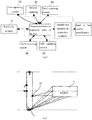
Fig. 4 is a schematic view of a module makeup of a container identification system according to some embodiments of the present disclosure; -
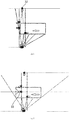
Fig. 5 is a schematic view of a state in which the container identification system according to the present disclosure captures an identification on a front end surface of the container; -
Fig. 6 is a schematic view of a state in which the container identification system according to the present disclosure captures an identification on a first side of the container; -
Fig. 7 is a schematic view of a state in which the container identification system according to the present disclosure captures an identification on a front area of a top surface of the container; -
Fig. 8 is a schematic view of a state in which the container identification system according to the present disclosure captures an identification on a second side of the container; -
Fig. 9 is a schematic view of a state in which the container identification system according to the present disclosure captures an identification on a rear area of a top surface of the container; -
Fig. 10 is a schematic view of a state in which the container identification system according to the present disclosure captures an identification on a rear end surface of the container; -
Fig. 11 is a schematic structural view of a safety inspection device according to some embodiments of the present disclosure; -
Fig. 12 is a schematic structural view of a safety inspection device according to other embodiments of the present disclosure. - The present disclosure is explained in detail below. In the following paragraphs, different aspects of the embodiments are defined in more detail. Each aspect thus defined may be combined with any other aspect or aspects unless it is specifically indicated that combination is impossible. In particular, any feature that is considered to be preferred or advantageous may be combined with one or more other features that are considered to be preferred or advantageous.
- The terms "first" and "second" recited in the present disclosure are merely for ease of description, to distinguish different constituent parts having the same name, rather than indicating a sequential or primary-secondary relationship.
- In the description of the present disclosure, it is necessary to understand that, the azimuth or positional relations indicated by terms "up", "down", "left", "right", "front", "rear", "inside" and "outside", which are based on the azimuth or positional relations illustrated by the drawings, are only for facilitating description of the present disclosure, rather than indicating or implying that the device referred thereto has to present a particular azimuth, and be constructed and operated in a particular azimuth, so that it cannot be understood as limiting the protection scope of the present disclosure
- The container number identification device known to the inventors has at least one of the following disadvantages: (1) when the RFID label is read, there are high requirements for label position and ambient environment, and the RFID label which needs to be continuously maintained is less cost-effective, and there is no image record, which makes it inconvenient to verify the correctness of an identification result; (2) a plurality of uprights and crossbars are fixed on the measurement site, with a large occupied area, a large number of sensors, a long debugging cycle for the sensors and a complicated layout and wiring, so that the arrangement of the components cannot even be completed at some special sites, with a restricted use. Therefore, there is a need to design a new container identification system.
- In view of this, the present disclosure improves the container identification system, and provides a container identification system, an identification method, a safety inspection device and a port facility, which can reduce the installation difficulty.
- In the container identification system according to the embodiments of the present disclosure, a door frame is provided with an area laser scanner and an identification obtaining apparatus. The area laser scanner is configured to detect a relative movement direction and a relative position of the container with the door frame. The identification obtaining apparatus is configured to obtain the identifications on respective sides of the container according to the position detection results of the area laser scanner. Such container identification system which integrates the area laser scanner and the identification obtaining apparatus on the door frame, may perform an integrated installation in a practical application, which improves the integration of the identification system, and occupies a small area, or may also be additionally installed on other door frame devices, thereby reducing the civil engineering work and the number of the installed brackets, with flexible and convenient use, and facilitating the installation and debugging, and also enhancing integrated transfer.
- The container identification system of the present disclosure is configured to identify the identification on the
container 1. As shown inFig. 1 , thecontainer 1 may be a container. For a specific identification manner of the identification code, IS06346:1995 Container Code, Identification and Marking standard of International Organization for Standardization stipulates the container identification system, size and container type code, as well as related identifications and identification methods. The identifications stipulated in the standard include: container owner code, device identification code, container number and check code. Specifically, as shown inFig. 1 , the identification of thecontainer 1 includes a group of serial numbers containing four Latin letters and seven Arabic numbers which consist of a size and a container type code A, a container number and a check code B, as well as a container owner code and a device identification code C. By using identification codes with a uniform standard, it is possible to improve the universal use of the system and facilitate obtaining the identification logic, and there is no need to make individual designs so that the cost is saved. Of course, the identification code may also be a two-dimensional code commonly used at present. - As shown in
Fig. 1 , the respective sides of thecontainer 1 include afirst side 11, asecond side 12, atop surface 13, afront end surface 14, and arear end surface 15, therear end surface 15 is a door end, thefirst side 11, thesecond side 12, thetop surface 13, thefront end surface 14 and therear end surface 15 are all marked with a size and a container code A, a container number and check code B, as well as a container owner code and a device identification code C. On the respective sides of thecontainer 1, the identifications are provided at different positions. - The present disclosure first provides a container identification system. In some embodiments, as shown in
Fig. 2 , the system includes: adoor frame 5, anarea laser scanner 2 and an identification obtaining apparatus, wherein thedoor frame 5 has a passage for thecontainer 1 to be identified to pass through; thearea laser scanner 2 is provided on thedoor frame 5 to detect a current position of thecontainer 1; the identification obtaining apparatus is disposed on thedoor frame 5 to obtain the identifications on the respective sides of thecontainer 1 according to the current position of thecontainer 1 relative to thedoor frame 5. - During the identification process, as long as the
container 1 moves relative to thedoor frame 5, which includes that: thedoor frame 5 is fixed, and thecontainer 1 mounted on a truck or an AGV vehicle passes through the passage; thecontainer 1 is not moved, and thedoor frame 5 is mounted on a mobile device so that it moves across thecontainer 1; thedoor frame 5 and thecontainer 1 are both in a movement state. Therefore, such container identification system has a favorable universal use. - Such container identification system may be fixedly provided in a site, or a roller is provided at a bottom end of the
door frame 5 to move on the track, or a movable wheel is provided at a bottom end of thedoor frame 5, or integrated in the safety inspection device, so that there is a wide application range. - The container identification system of the embodiments of the present disclosure has at least one of the following advantages:
- (1) The area laser scanner and the identification obtaining apparatus are integrated on the door frame, so that an integrated installation may be performed in a practical application, which improves the integration of the identification system, and occupies a small area, or an additional installation on other door frame devices may also be possible, thereby reducing the civil engineering work and the number of the installed brackets, with flexible and convenient use, and facilitating the installation and debugging, and also enhancing integrated transfer.
- (2) By using a door frame identification system, it is possible to allow that the arrangement of components makes full use of the space in a height direction so as to reduce the space occupied within a horizontal plane, thereby improving the adaptability to different occasions. In addition, each component may be installed on the door frame in advance. During field installation, it is necessary to install the door frame, which may improve the installation efficiency.
- (3) By using the area laser scanner to detect the position of the container, since the area laser scanner may emit a plurality of laser beam signals to form a laser beam scanning sector area to detect the container position, it is only necessary to provide one area laser scanner so as to be able to accurately obtain the position of the container and the positions of the identifications on respective sides, thereby lessening the number of sensors, shortening the debugging cycle, and reducing the layout and wiring difficulty.
- (4) The real-time position information of the container is obtained using the area laser scanner, thereby facilitating the system to more flexibly choose a position at which the identification obtaining apparatus is arranged, and reducing the layout difficulty of the components, so that it is compatible with a plurality of applications.
- In some embodiments, as shown in
Fig. 2 and Fig.3 , thedoor frame 5 includes across beam 51 and twolongitudinal beams 52, wherein the twolongitudinal beams 52 are respectively connected to both ends of thecross beam 51. - In some embodiments, as shown in
Fig. 2 , thearea laser scanner 2 is disposed on one of thelongitudinal beams 52, and the laser irradiation surface faces towards the passage. Referring toFig. 7 , thearea laser scanner 2 emits a sector-shaped laser beam from thelongitudinal beam 52, which may entirely cover the passage through which thecontainer 1 passes. Alternatively, thearea laser scanner 2 may be also provided on thecross beam 51. - By providing the
area laser scanner 2, it is possible to automatically determine the entering direction of the vehicle on which thecontainer 1 is mounted along the passage. Regardless of the direction in which thecontainer 1 enters the passage, it is possible to determine the type and number of thecontainer 1 mounted on the vehicle passing through the passage, and at the same time obtain the size code and the container type code of thecontainer 1. - In some embodiments, the
area laser scanner 2 is configured to identify the front end surface of thecontainer 1 along a movement direction. When the vehicle on which thecontainer 1 is mounted approaches thedoor frame 5, thearea laser scanner 2 can distinguish the front end surface of the vehicle from thefront end surface 14 of thecontainer 1 in order to start the identification process. - In some embodiments, still referring to
Fig. 1 andFig.2 , the identification obtaining apparatus includes a plurality of capturing cameras, which are disposed at different positions on thedoor frame 5 to capture the identifications on different surfaces of thecontainer 1 respectively. By using a capturing camera to obtain the identification has a low requirement for the ambient environment, which may reduce the maintenance frequency, and facilitate verifying the correctness of the identification result by image recording. In some embodiments, the capturing camera is a web camera, which can directly upload the capturing result to the control system. - The container identification system also includes a controller. The
area laser scanner 2 is configured to detect the distance between the camera and the end surface of thecontainer 1 so as to determine the current position of thecontainer 1. The controller is configured to determine the distance between the capturing camera and the end surface of thecontainer 1 to determine the moment when the respective capturing cameras are enabled. - Since the identifications on the respective sides of the
container 1 are at different positions along its movement direction, by determining the distance between each of the capturing cameras and the end surface of the container, each of the capturing cameras may capture the identification on a side to be captured when a proper distance is reached, so that it is possible to improve the accuracy of the identification result. - Specifically, referring to
Fig. 5 to Fig. 10 , thearea laser scanner 2 is configured to detect a distance between the capturing camera and thefront end surface 14, and the controller is configured to determine a timing when the capturing cameras are enabled for capturing thefront end surface 14, thefirst side 11 and the front area of thetop surface 13 of thecontainer 1 according to the distance between the capturing camera and thefront end surface 14. The identification on thefirst side 11 is disposed proximate to thefront end surface 14. Since the identifications on thefirst side 11 and the front area oftop surface 13 are closer to thefront end surface 14, the timing when the cameras are enabled to identify the identifications on thefront end surface 14, thefirst side 11, and the front area of thetop surface 13 with thefront end surface 14 as a reference, which facilitates improving the accuracy of the distance detection, thereby improving the accuracy of the identification result. - Alternatively, the
area laser scanner 2 is configured to detect a distance between the capturing camera and therear end surface 15, and the controller is configured to determine a timing when the capturing cameras are enabled for capturing therear end surface 15, thesecond side 12, and the rear area of thetop surface 13 of the container according to the distance between the capturing camera and therear end surface 15. The identification on thesecond side 12 is disposed proximate to therear end surface 15. Since the identifications on thesecond side 12 and the rear area of thetop surface 13 are closer to therear end surface 15, the timing when the capturing cameras are enabled to identify therear end surface 15, thesecond side 12, and the rear area of thetop surface 13 are determined with therear end surface 15 as a reference, which facilitates improving the accuracy of the distance detection, thereby improving the accuracy of the identification result. - During the container number identification process, only one capturing camera is in an enabled state at the same moment. In this manner, each capturing camera can identify the identification when a proper distance is reached, thereby improving the quality of the captured image, and the plurality of capturing cameras can not be interfered during operation, thereby facilitating accurately obtaining the identifications on the container. Moreover, it is also possible to reduce the calculation processing amount performed by the controller at the same moment, which may reduce the requirements for the calculation processing capacity of the processor.
- In some embodiments, as shown in
Fig. 2 and Fig.3 , the container identification system further includes a plurality of fill lights, which are provided on thedoor frame 5 for supplementing light sources for the capturing cameras at adjacent positions so as to improve the definition of the captured image or video, thereby improving the accuracy of the identification. - In some embodiments, the
door frame 5 includes across beam 51 and twolongitudinal beams 52. The twolongitudinal beams 52 are respectively connected to both ends of thecross beam 51, and the respective capturing cameras are disposed on thecross beam 51 and the longitudinal beams 52. According to the needs in different sides of the capturingcontainer 1, the capturing cameras may be provided at different positions of thedoor frame 5. - As shown in
Fig. 5 , the plurality of capturing cameras are arranged at intervals along at least one of the length direction and width direction of thecross beam 51 according to the positions where the identifications are provided on different surfaces of thecontainer 1. By arranging the capturing cameras at intervals in the width direction of thecross beam 51 and facing the capturing surfaces towards different directions, it is possible to flexibly capture the identifications on different sides of thecontainer 1. - In some embodiments, the capturing directions of the plurality of capturing cameras are different, the number of the capturing cameras is the same as that of the surfaces of the
container 1 on which identifications are provided, and the plurality of capturing camera are configured to obtain the identifications on different surfaces of thecontainer 1. In this embodiment, it is possible to reduce the number of the capturing cameras provided and reduce the cost whilst capturing the identifications on the respective sides of thecontainer 1. - In some embodiments, as shown in
Fig. 4 , the container identification system of the present disclosure further includes a controller for receiving the identifications obtained by the plurality of capturing cameras, and extracting identification results for voting to output a final identification result. According to the positions of the respective surfaces of thecontainer 1 obtained by thelaser area scanner 2, different capturing cameras perform identification at different moments, and the identification results of the plurality of capturing cameras are sent to the controller, which determines the final identification result in a voting manner, thereby improving the accuracy of the identification. - In some embodiments, the identification obtaining apparatus includes five capturing cameras, which are as follows:
- A
first capturing camera 31, as shown inFig. 3 andFig.5 , is disposed on an edge position of thecross beam 51 proximate to an entry side of thecontainer 1, and configured to capture the identification on thefront end surface 14 of thecontainer 1 along the movement direction. Correspondingly, along a length direction of thecross beam 51, afirst fill light 41 and a second fill light 41' may be provided on thecross beam 51 on both sides of thefirst capturing camera 31 respectively. - A
second capturing camera 32, as shown inFig. 2 andFig.6 , is disposed on alongitudinal beam 52 on an opposite side of thearea laser scanner 2, and configured to capture the identification on thefirst side 11 of thecontainer 1 opposite to thesecond capturing camera 32. Correspondingly, athird fill light 42 may be provided on thelongitudinal beam 52 above or below thesecond capturing camera 32. - A
third capturing camera 33, as shown inFig. 2 ,Fig.7 , andFig.9 , is disposed on an edge position of thecross beam 51 proximate to an exit side of thecontainer 1, and located at a center position of thecross beam 51 along the length direction, for capturing the identifications on the front area and the rear area of thetop surface 13 of thecontainer 1. Correspondingly, afourth fill light 43 may be provided on thecross beam 51 outside thethird capturing camera 33. - A
fourth capturing camera 34, as shown inFig. 2 andFig.8 , is disposed on thelongitudinal beam 52 on the same side as thearea laser scanner 2, and configured to capture the identification on thesecond side 12 of thecontainer 1 opposite to thefourth capturing camera 34. Correspondingly, afifth fill light 44 may be provided on thelongitudinal beam 52 above or below thefourth capturing camera 34; and - A
fifth capturing camera 35, as shown inFig. 2 andFig. 10 , is disposed on an edge position of thecross beam 51 proximate to the exit side of thecontainer 1, and biased from the center position of thecross beam 51 along the length direction, for capturing the identification on therear end surface 15 of thecontainer 1 along the movement direction. Correspondingly, asixth fill light 45 may be provided on thecross beam 51 outside thefifth capturing camera 35. - In this embodiment, by way of a reasonable layout of the respective capturing camera on the
door frame 5, the respective capturing cameras may be arranged on thedoor frame 5 with a narrow size along the passage extending direction. Such arrangement manner may allow that the capturing of the respective capturing cameras for the respective sides of thecontainer 1 is not affected by the size of thedoor frame 5 along the passage extending direction, so that it is possible to reduce the size of thedoor frame 5 along the passage width direction, thereby further reducing the occupied space, and realizing a lightweight design. - As shown in
Fig. 5 to Fig. 10 , thesecond capturing camera 32 and thefourth capturing camera 34 irradiate toward the inside of thedoor frame 5, and thefirst capturing camera 31, thethird capturing camera 33, and thefifth capturing camera 35 irradiate toward the outside of thedoor frame 5. The irradiation direction of thefifth capturing camera 35 is inclined toward the center line in the length direction of thecross beam 51. The positions at which the respective capturing cameras are provided as well as the irradiation directions can align them with the identifications on the corresponding sides of thecontainer 1. - In some embodiments, in order to improve the universal use of the container identification system, the
cross beam 51 and the twolongitudinal beams 52 may be designed to be structures with an adjustable length, so as to adapt to thecontainer 1 of different widths and heights by adjusting the size of the passage size. - In
such door frame 5, at least one of the width and height of the passage may be increased when the size of thecontainer 1 is large, so that thecontainer 1 can pass smoothly and prevent damage to thearea laser scanner 2 and the identification obtaining apparatus; and at least one of the width and height of the passage may be decreased when the size of thecontainer 1 is small, so that each component is within a proper operation distance, thereby improving the accuracy of obtaining the identification information. In addition, when the container identification system is integrated in the door frame of the safety inspection device, theadjustable door frame 5 may also adapt to the door frame size of the safety inspection device, thereby facilitating integration with the safety inspection device. - In some embodiments, since the positions where the identifications are provided on
different containers 1 are also different, thearea laser scanner 2 and the identification obtaining apparatus may be installed on thedoor frame 5 through a base on which a position adjustment mechanism and an attitude adjustment mechanism are provided. The position adjustment mechanism is configured to change a position where thearea laser scanner 2 and/or the identification obtaining apparatus provided on thedoor frame 5, and the attitude adjustment mechanism is configured to change the installation an attitude of thearea laser scanner 2 and/or the identification obtaining apparatus. - In this embodiment, it is possible to flexibly adjust at least one of the installation position and the installation attitude of the respective components according to the position where the identifications are provided on the
container 1, so as to achieve a more accurate identification result and improve the universal use. - In each of the above-described embodiments, the identification includes: at least one of a container owner code, a device identification code, a container number, a check code, a size, and a container type code.
- The operation principles of the container identification system of the present disclosure will be described below in conjunction with
Fig. 5 to Fig. 10 . The arrows indicate the movement direction of thecontainer 1 relative to thedoor frame 5 within the passage. Such movement that is relative neither delimits the direction of the relative movement, nor delimits that either of the automatic identification system or the identified container is in an absolutely stationary state. At the same time, the system does not delimit the size of the gap between the containers and the number of containers continuously passing through the passage when the containers pass through the identification passage. - When the
area laser scanner 2 detects that thecontainer 1 moves to a preset position, thearea laser scanner 2 identifies thefront end surface 14 of thecontainer 1 along the movement direction, and instructs the identification obtaining apparatus to carry out action processes such as capturing preparation and formal capturing. The capturing preparation actions include, but are not limited to, collection of ambient illuminance, calculation of capturing exposure parameters and gain parameters, whether to use light fill measures by lamps and the like. The formal capturing actions may be photographing or capturing video images. - When the
container 1 travels to the position shown inFig. 5 , at this time, thearea laser scanner 2 detects that the distance between thefirst capturing camera 31 and thefront end surface 14 of thecontainer 1 reaches a first preset value, and thefirst capturing camera 31 is enabled to obtain and store the identification size and the container type code A, the container number and the check code B, as well as the container owner code and the device identification code C on thefront end surface 14 of thecontainer 1. - When the
container 1 continues to move forward to the position shown inFig. 6 , at this time, thearea laser scanner 2 detects that thefront end surface 14 of thecontainer 1 exceeds the second preset value of thesecond capturing camera 32, and thesecond capturing camera 32 is enabled to obtain and store the identification on thefirst side 11 of thecontainer 1. - When the
container 1 continues to travel to the position shown inFig. 7 , at this time, thearea laser scanner 2 detects that thefront end surface 14 of thecontainer 1 goes beyond thethird camera 33, and the distance between thethird camera 33 and thefront end surface 14 reaches a third preset value, thethird capturing camera 33 is enabled to obtain and store the identification on the front area of thetop surface 13 of thecontainer 1. - When the
container 1 continues to travel to the position shown inFig. 8 , thearea laser scanner 2 detects that thefourth capturing camera 34 is located in front of therear end surface 15 and the distance reaches a fourth preset value, thefourth capturing camera 34 is enabled obtain and store the identification on thesecond side 12 of thecontainer 1. - When the
container 1 continues to travel to the position shown inFig. 9 , thearea laser scanner 2 detects that thecontainer 1 leaves thedoor frame 5 and the distance between thethird capturing camera 33 and therear end 15 reaches a fifth preset value, thethird capturing camera 33 is enabled to obtain and store the identification on the rear area of thetop surface 13 of thecontainer 1. - When the
container 1 continues to travel to the position shown inFig. 10 , thearea laser scanner 2 detects that the distance between thefifth capturing camera 35 and therear end surface 15 reaches a sixth preset value, and thefifth capturing camera 35 is enabled to obtain and store the identification on therear end surface 15 of thecontainer 1. After thecontainer 1 leaves the container identification system, six identifications on thecontainer 1 may be obtained by five capturing cameras. - It is assumed that the arrow direction in the drawings is a forward direction of the movement of the
container 1. When thecontainer 1 passes through the passage in a reverse direction, the capturing may be performed in a completely reverse order. Regardless of whether the container pass therethrough in a forward direction or in a reverse direction, it is not limited to an entry direction of a next vehicle on which thecontainer 1 is mounted. Thus, such container identification system may identify at least one of the container number, the container type, and the number of containers passing through thedoor frame 5. - Next, the present disclosure also provides an identification method based on the container identification system of the above-described embodiments. In some embodiments, the method includes:
- detecting the current position of the
container 1 through thearea laser scanner 2; and - obtaining the identifications on the respective sides of the
container 1 according to the current position of thecontainer 1 through the identification obtaining apparatus. - In some embodiments, the identification obtaining apparatus includes a plurality of capturing cameras, which are respectively configured to capture the identifications on different sides of the
container 1. The container identification method further includes: - receiving the identifications obtained by the respective capturing cameras; and
- extracting the identification results from the identifications obtained by the plurality of capturing cameras; and
- outputting a final identification result after voting on the respective identification results.
- The steps in this embodiment may be performed by the controller. According to the positions of the respective sides of the
container 1 obtained by thelaser area scanner 2, different capturing cameras perform identification at different moments, and the identification results of the respective capturing cameras are sent to the controller, which determines the final identification result in a voting manner, so as to improve the accuracy of the identification. - In some embodiments, the identification obtaining apparatus includes a plurality of capturing cameras, which are respectively configured to capture the identifications on different sides of the
container 1. The step of obtaining the identifications on the respective surfaces of thecontainer 1 by the identification obtaining apparatus according to the relative movement direction and the relative position of thecontainer 1 and thedoor frame 5 includes: - detecting a distance between the capturing camera and the end surface of the
container 1 by thearea laser scanner 2; and - determining the timing when the plurality of capturing cameras are enabled by the controller according to the distance between the capturing camera and the end surface of the
container 1. - For the container identification system of
Fig. 2 and Fig.3 , in one specific embodiment, the step of obtaining the identifications on the respective surfaces of thecontainer 1 by the identification obtaining apparatus according to the current position of thecontainer 1 specifically includes: - (1) When the
area laser scanner 2 detects that the distance between thefirst capturing camera 31 and thefront end surface 14 of thecontainer 1 reaches the first preset value, thefirst capturing camera 31 is enabled to obtain the identification on thefront end surface 14; - (2) When the
area laser scanner 2 detects that thecontainer 1 moves to thefront end surface 14 and exceeds the second preset value of thesecond capturing camera 32, thesecond capturing camera 32 is enabled to obtain the identification on thefirst side 11, wherein the identification on thefirst side 11 is proximate to thefront end surface 14; - (3) When the
area laser scanner 2 detects that the distance between thethird capturing camera 33 and thefront end surface 14 reaches the third preset value, thethird capturing camera 33 is enabled to obtain the identification on the front area of thetop surface 13; - (4) When the
area laser scanner 2 detects that thefourth capturing camera 34 is located in front of therear end surface 15 and the distance reaches the fourth preset value, thefourth capturing camera 34 is enabled to obtain the identification on thesecond side 12, wherein the identification on thesecond side 12 is proximate to therear end 15; - (5) When the
area laser scanner 2 detects that thecontainer 1 leaves thedoor frame 5 and the distance between thethird capturing camera 33 and therear end surface 15 reaches the fifth preset value, thethird capturing camera 33 is enabled to obtain the identification on the rear area of thetop surface 13. - (6) When the
area laser scanner 2 detects that the distance between thefifth capturing camera 35 and therear end surface 15 reaches the sixth preset value, thefifth capturing camera 35 is enabled to obtain the identification on therear end surface 15. - The steps (2) and (3) are interchangeable according to the front and rear positions of the identifications on the
first side 11 and the front area of thetop surface 13 of thecontainer 1; and the steps (4) and (5) are interchangeable according to the front and rear positions of the identifications on thesecond side 12 and the rear area of thetop surface 13 of thecontainer 1. - In addition, the present disclosure also provides a safety inspection device, as shown in
Fig. 11 andFig. 12 , including the container identification system of the above-described embodiments. Such safety inspection device that also adds a container identification function on the basis of the inherent container interior scanning function, may enable at least one of the container identification function and the container interior scanning function as required. - If both functions are enabled at the same time, when the
container 1 passes through the scanning passage of the safety inspection device, it is not only possible to inspect the conditions of goods inside thecontainer 1 through a probe arm, but also possible to identify the identifications on thecontainer 1 at the same time. Since the two steps are carried out simultaneously, it is possible to improve the efficiency of scanning inspections and obtaining the identifications. - In some embodiments, the container identification system is installed on the
boom 6 of the safety inspection device, including a fixed installation and a detachable installation. The safety inspection device in which the container identification system is detachably installed may decide whether to add a container identification system according to user needs, or can also flexibly replace different types or specifications of container identification systems. - As shown in
Fig. 11 , the safety inspection device includes aboom 6, afirst cabin 7 and asecond cabin 8. Theboom 6 is in the form of a gantry, including a transverse arm and vertical arms provided at both ends of the transverse arm. Two vertical arms are installed on thefirst cabin 7 and thesecond cabin 8 respectively. The container identification system is directly installed on theboom 6 of the safety inspection device through thedoor frame 5. The container identification system is installed on the safety inspection device as an independent module, which facilitates the installation. Such installation manner is suitable for the safety inspection device that uses a boom in the form of a gantry. - In other embodiments, the
boom 6 of the safety inspection device directly serves as thedoor frame 5 of the container identification system. That is, thearea laser scanner 2 and the identification obtaining apparatus are directly integrated on theboom 6 of the safety inspection device. This embodiment may simplify the structure of theboom 6 of the safety inspection device, thereby reducing the weight, and preventing deformation of theboom 6. - As shown in
Fig. 12 , the safety inspection device includes aboom 6 and a radiation source. Theboom 6 is in the form of an L-shaped cantilever. Since the vertical arm on an installation side of theboom 6 has a short length so that it is not convenient to install thedoor frame 5, theboom 6 may directly serve as thedoor frame 5 of the container identification system so as to reduce the weight of theboom 6, and prevent deformation of theboom 6 without affecting the collapse of theboom 6. For example, thearea laser scanner 2 and the identification obtaining apparatus may be installed on one side of theboom 6 along the inspection passage so as not to affect the installation of the detector. The radiation scanning system and the container identification system may share thearea laser scanner 2 for detecting a movement position of the container, and the controller is configured to enable the radiation source when the container is about to reach theboom 6, and obtain the identifications on the respective sides of thecontainer 1 according to the current position of thecontainer 1. Such structure can reduce the use of position detecting members and simplify the structure. - The safety inspection device of the present disclosure may be a stationary, track-based mobile, or traveling safety inspection device or the like.
- Finally, the present disclosure also provides a port facility including at least one of the container identification system of the above-described embodiments and the safety inspection device of the above-described embodiments. In smart ports, the container identification system may be fixed in the site, or on the track, or integrated in the safety inspection device.
- In some embodiments, the port facility further includes a
container 1, and the identifications provided on different sides of the container are the same. Generally, the positions where the identifications are provided on the respective sides of the general container are fixed. - In some embodiments, a plurality of identifications are arranged asymmetrically on the container, and a plurality of capturing cameras are arranged asymmetrically within the passage, so as to sequentially obtain the identification information in different orientations of the container. Compared to a simultaneously obtaining manner, by sequentially obtaining the identification information in different orientations of the container, it is possible to reduce the calculation processing amount performed by the processor at the same time, thereby reducing the requirements for the calculation processing capacity of the processor. Moreover, the sequentially obtaining manner also facilitates accurately obtaining the identifications on the container.
- The container identification system, identification method, safety inspection device and port facility provided by the present disclosure have been described in detail above. Specific examples are applied herein to explain the principles and embodiments of the present disclosure. The descriptions of the above embodiments are only intended to help understand the methods and core ideas of the present disclosure. It should be noted that for those of ordinary skill in the art, without departing from the principles of the present disclosure, several improvements and modifications may be also made to the present disclosure, and these improvements and modifications also fall within the protection scope of the claims of the present disclosure.
Claims (22)
- A container identification system, comprising:a door frame (5), having a passage for a container (1) to be identified to pass through;an area laser scanner (2), disposed on the door frame (5) to detect a current position of the container (1); andan identification obtaining apparatus, disposed on the door frame (5) to obtain identifications on respective surfaces of the container (1) according to the current position of the container (1).
- The container identification system according to claim 1, wherein the door frame (5) comprises a cross beam (51) and two longitudinal beams (52) which are connected on both ends of the cross beam (51) respectively, the area laser scanner (2) is arranged on one of the longitudinal beams (52), and a laser irradiation surface of the area laser scanner (2) faces towards the passage.
- The container identification system according to claim 1, wherein the area laser scanner (2) is configured to identify a front end surface of the container (1) along a movement direction.
- The container identification system according to claim 1, wherein the identification obtaining apparatus comprises a plurality of capturing cameras, which are disposed at different positions on the door frame (5) to capture identifications on different surfaces of the container (1) respectively.
- The container identification system according to claim 4, further comprising a controller, wherein the area laser scanner (2) is configured to detect a distance between the capturing camera and an end surface of the container (1) so as to determine the current position of the container (1), and the controller is configured to determine a timing when the plurality of capturing cameras are enabled according to the distance between the capturing camera and the end surface of the container (1).
- The container identification system according to claim 5, wherein the area laser scanner (2) is configured to detect a distance between the capturing camera and a front end surface (14), and the controller is configured to determine a timing when the capturing cameras are enabled for capturing the front end surface (14), a first side (11), and a front area of a top surface (13) of the container according to the distance between the capturing camera and the front end surface (14), wherein an identification on the first side (11) is disposed proximate to the front end surface (14); and/or
the area laser scanner (2) is configured to detect a distance between the capturing camera and a rear end surface, and the controller is configured to determine a timing when the capturing cameras are enabled for capturing the rear end surface (15), a second side (12) and a rear area of a top surface (13) of the container according to the distance between the capturing camera and the rear end surface (15), wherein an identification on the second side (12) is disposed proximate to the rear end surface (15). - The container identification system according to claim 4, wherein only one of the capturing cameras is in an enabled state at the same moment.
- The container identification system according to claim 4, wherein the door frame (5) comprises a cross beam (51) and two longitudinal beams (52) which are connected on both ends of the cross beam (51) respectively, and the plurality of capturing cameras are disposed on the cross beam (51) and the longitudinal beams (52).
- The container identification system according to claim 8, wherein the plurality of the capturing cameras are arranged at intervals along at least one of a length direction and a width direction of the cross beam (51) according to positions where identifications are provided on different surfaces of the container (1).
- The container identification system according to claim 4, wherein the plurality of capturing cameras have different capturing directions, the number of the capturing cameras is the same as that of the surfaces of the container (1) on which identifications are provided, and the plurality of capturing cameras are configured to obtain identifications on different surfaces of the container (1).
- The container identification system according to claim 4, further comprising a controller configured to receive identifications obtained by the plurality of capturing cameras, and extract identification results for voting to output a final identification result.
- The container identification system according to claim 2, wherein the identification obtaining apparatus comprises:a first capturing camera (31), disposed on an edge position of the cross beam (51) proximate to an entry side of the container (1), and biased towards a first side of a center position of the cross beam (51) along a length direction, configured to capture an identification on a front end surface (14) of the container (1) along a movement direction;a second capturing camera (32), disposed on a longitudinal beam (52) on an opposite side of the area laser scanner (2), and configured to capture an identification on a first side (11) of the container (1) opposite to the second capturing camera (32);a third capturing camera (33), disposed on an edge position of the cross beam (51) proximate to an exit side of the container (1), and at a center position of the cross beam (51) along the length direction, and configured to capture an identification on a top surface (13) of the container (1);a fourth capturing camera (34), disposed on a longitudinal beam (52) on the same side as the area laser scanner (2), and configured to capture an identification on a second side (12) of the container (1) opposite to the fourth capturing camera (34); anda fifth capturing camera (35), disposed on an edge portion of the cross beam (51) proximate to an exit side of the container (1), and biased toward a second side on a center position of the cross beam (51) along the length direction, and configured to capture an identification on a rear end surface (15) of the container (1).
- The container identification system according to claim 12, wherein the second capturing camera (31) and the fourth capturing camera (34) irradiate toward an inside of the door frame (5), and the first capturing camera (31), the third capturing camera (33) and the fifth capturing camera (35) irradiate toward an outside of the door frame (5), and an irradiation direction of the fifth capturing camera (35) is inclined toward a center line of the length direction of the cross beam (51).
- The container identification system according to claim 1, wherein the door frame (5) comprises a cross beam (51) and two longitudinal beams (52), and at least one of the cross beam (51) and the longitudinal beam (52) has an adjustable length.
- The container identification system according to claim 1, further comprising a base through which the area laser scanner (2) and the identification obtaining apparatus are both mounted on the door frame (5), wherein the base is provided with at least one of a position adjustment mechanism and an attitude adjustment mechanism, wherein:the position adjustment mechanism is configured to change a position where the area laser scanner (2) or the identification obtaining apparatus disposed on the door frame (5); andthe attitude adjustment mechanism is configured to change an installation attitude of the area laser scanner (2) or the identification obtaining apparatus.
- An identification method based on the container identification system according to any one of claims 1 to 15, comprising:detecting the current position of the container (1) by the area laser scanner (2); andobtaining identifications on respective surfaces of the container (1) by the identification obtaining apparatus according to the current position of the container (1).
- The container identification method according to claim 16, wherein the identification obtaining apparatus comprises a plurality of capturing cameras respectively configured to capture identifications on different surfaces of the container (1), and the container identification method further comprises:receiving identifications obtained by the plurality of capturing cameras;extracting identification results from the identifications obtained by the plurality of capturing cameras; andoutputting a final identification result after voting on the identification results.
- The container identification method according to claim 16, wherein the identification obtaining apparatus comprises a plurality of capturing cameras respectively configured to capture identifications on different surfaces of the container (1), and the step of obtaining identifications on respective surfaces of the container (1) by the identification obtaining apparatus according to the current position of the container (1) comprises:detecting a distance between the capturing camera and an end surface of the container (1) by the area laser scanner (2); anddetermining a timing when the plurality of capturing cameras are enabled according to the distance between the capturing camera and the end surface of the container (1).
- The container identification method according to claim 16, wherein the identification obtaining apparatus comprises a plurality of capturing cameras respectively configured to capture identifications on different surfaces of the container (1), so that the step of obtaining identifications on respective sides of the container (1) by the identification obtaining apparatus according to the current position of the container (1) comprises:detecting a distance between the capturing camera and a front end surface (14) by the area laser scanner (2);determining a timing when the capturing cameras are enabled for capturing the front end surface (14), a first side (11) and a front area of a top surface (13) of the container according to the distance between the capturing camera and the front end surface (14); and/orthe step of obtaining identifications on respective sides of the container (1) by the identification obtaining apparatus according to the current position of the container (1) comprises:detecting a distance between the capturing camera and a rear end surface (15) by the area laser scanner (2);determining a timing when the capturing cameras are enabled for capturing the rear end surface (15), a second side (12) and a rear area of a top surface (13) of the container according to the distance between the capturing camera and the rear end surface (15), wherein an identification on the second side (12) is disposed proximate to the rear end surface (15).
- The container identification method according to claim 16, wherein the step of obtaining identifications on respective sides of the container (1) by the identification obtaining apparatus according to the current position of the container (1) comprises:enabling a first capturing camera (31) to obtain an identification on a front end surface (14) when the area laser scanner (2) detects that a distance between the first capturing camera (31) and the front end surface (14) of the container (1) reaches a first preset value;enabling a second capturing camera (32) to obtain an identification on a first side (11) when the area laser scanner (2) detects that the container (1) moves to the front end surface (14) exceeds a second preset value of the second capturing camera (32), wherein the identification on the first side (11) is proximate to the front end surface (14);enabling a third capturing camera (33) to obtain an identification on a front area of a top surface (13) when the area laser scanner (2) detects that a distance between the third capturing camera (33) and the front end surface (14) reaches a third preset value;enabling a fourth capturing camera (34) to obtain an identification on a second side (12) when the area laser scanner (2) detects that the fourth capturing camera (34) is located in front of a rear end surface (15), and with a distance from the rear end surface (15) reaching a fourth preset value, wherein the identification on the second side (12) is proximate to the rear end (15);enabling a third capturing camera (33) to obtain an identification on a rear area of the top surface (13) when the area laser scanner (2) detects that the container (1) leaves the door frame (5) and a distance between the third capturing camera (33) and the rear end surface (15) reaches a fifth preset value; andenabling a fifth capturing camera (35) to obtain an identification on the rear end surface (15) when the area laser scanner (2) detects that a distance between the fifth capturing camera (35) and the rear end surface (15) reaches a sixth preset value.
- A safety inspection device, comprising the container identification system according to any one of claims 1 to 15, wherein the container identification system is installed on a boom (6) of the safety inspection device; or a boom (6) of the safety inspection device directly serves as a door frame (5) of the container identification system.
- A port facility, comprising at least one of the container identification system according to any one of claims 1 to 15 and the safety inspection device according to claim 21.
Applications Claiming Priority (2)
| Application Number | Priority Date | Filing Date | Title |
|---|---|---|---|
| CN201910009508.0A CN109492449A (en) | 2019-01-04 | 2019-01-04 | Cabinet identifying system, checks equipment and port facilities at recognition methods |
| PCT/CN2020/070304 WO2020140978A1 (en) | 2019-01-04 | 2020-01-03 | Container identification system and method, safety inspection device, and port facility |
Publications (2)
| Publication Number | Publication Date |
|---|---|
| EP3796207A1 true EP3796207A1 (en) | 2021-03-24 |
| EP3796207A4 EP3796207A4 (en) | 2022-02-09 |
Family
ID=65714045
Family Applications (1)
| Application Number | Title | Priority Date | Filing Date |
|---|---|---|---|
| EP20736194.0A Pending EP3796207A4 (en) | 2019-01-04 | 2020-01-03 | CONTAINER IDENTIFICATION SYSTEM AND METHOD, SECURITY INSPECTION SYSTEM AND PORT FACILITY |
Country Status (3)
| Country | Link |
|---|---|
| EP (1) | EP3796207A4 (en) |
| CN (1) | CN109492449A (en) |
| WO (1) | WO2020140978A1 (en) |
Families Citing this family (8)
| Publication number | Priority date | Publication date | Assignee | Title |
|---|---|---|---|---|
| CN109492449A (en) * | 2019-01-04 | 2019-03-19 | 清华大学 | Cabinet identifying system, checks equipment and port facilities at recognition methods |
| CN110348451B (en) * | 2019-07-18 | 2022-12-13 | 西南交通大学 | Automatic collection and identification method of container number during railway container loading and unloading |
| WO2021258195A1 (en) * | 2020-06-22 | 2021-12-30 | Canscan Softwares And Technologies Inc. | Image-based system and method for shipping container management with edge computing |
| CN111753734A (en) * | 2020-06-24 | 2020-10-09 | 深圳中集智能科技有限公司 | Container number identification system, identification method and electronic device |
| CN114202041B (en) * | 2020-09-18 | 2025-02-11 | 顺丰科技有限公司 | Packaging material detection method and device |
| US20250356665A1 (en) * | 2022-04-20 | 2025-11-20 | Atai Labs Private Limited | System and method for detecting and identifying container number in real-time |
| CN115490150B (en) * | 2022-08-31 | 2025-06-03 | 西门子(中国)有限公司 | Lifting equipment for container and method for detecting orientation of container |
| CN115830585B (en) * | 2022-12-05 | 2026-04-21 | 浙江海洋大学 | A Port Container Number Recognition Method Based on Image Enhancement |
Family Cites Families (8)
| Publication number | Priority date | Publication date | Assignee | Title |
|---|---|---|---|---|
| EP2126804A1 (en) * | 2006-12-21 | 2009-12-02 | Lorquon Holdings PTY LTD | Baggage handling system and process for a transport vehicle |
| EP2730532A1 (en) * | 2012-11-09 | 2014-05-14 | CAMCO Technologies NV | A container scanning system |
| CN106709390A (en) * | 2015-11-13 | 2017-05-24 | 北京兆维电子(集团)有限责任公司 | Barcode continuous recognition device |
| CN106324693B (en) * | 2016-08-30 | 2019-04-19 | 北京华力兴科技发展有限责任公司 | Self-travel type container/vehicle inspection equipment |
| CN207263653U (en) * | 2017-10-11 | 2018-04-20 | 杭州海康机器人技术有限公司 | Container table surface detection system and container car inspection post |
| CN108036778B (en) * | 2017-12-26 | 2024-04-02 | 清华大学 | Container automatic identification system and identification method and port facility |
| CN109492449A (en) * | 2019-01-04 | 2019-03-19 | 清华大学 | Cabinet identifying system, checks equipment and port facilities at recognition methods |
| CN209248542U (en) * | 2019-01-04 | 2019-08-13 | 清华大学 | Cabinet identifying system checks equipment and port facilities |
-
2019
- 2019-01-04 CN CN201910009508.0A patent/CN109492449A/en active Pending
-
2020
- 2020-01-03 EP EP20736194.0A patent/EP3796207A4/en active Pending
- 2020-01-03 WO PCT/CN2020/070304 patent/WO2020140978A1/en not_active Ceased
Also Published As
| Publication number | Publication date |
|---|---|
| EP3796207A4 (en) | 2022-02-09 |
| CN109492449A (en) | 2019-03-19 |
| WO2020140978A1 (en) | 2020-07-09 |
Similar Documents
| Publication | Publication Date | Title |
|---|---|---|
| WO2020140978A1 (en) | Container identification system and method, safety inspection device, and port facility | |
| EP3290963B1 (en) | Movable divided inspection system and method | |
| US11965836B2 (en) | Assembly for detecting defects on a motor vehicle bodywork | |
| EP4043693B1 (en) | Image acquisition device for tunnel inspection, tunnel inspection system, and tunnel inspection method | |
| US9817149B2 (en) | Vehicle inspection system | |
| EP2988151B1 (en) | Vehicle inspection system | |
| US8983030B2 (en) | Inspection machine for printed circuit board | |
| US20090147913A1 (en) | X-ray scanner | |
| EP3495852B1 (en) | An equipment and method for scanning a carriage of a train | |
| US20160187526A1 (en) | Vehicle-carried quick inspection system | |
| US9783366B2 (en) | Vehicle dragging system and vehicle inspection system | |
| CN105403162B (en) | The automatic testing method of semitrailer outer profile size | |
| CN217717531U (en) | Detection device and battery manufacturing equipment | |
| WO2020010970A1 (en) | Radiation inspection system | |
| AU2025202057A1 (en) | Single Pass Automated Vehicle Inspection System and Method | |
| CN111694063B (en) | Safety inspection device and safety inspection method for motor vehicle trunk | |
| EP4645217A1 (en) | Vehicle inspection method and system, and storage medium | |
| CN210775269U (en) | Detection equipment | |
| CN209248542U (en) | Cabinet identifying system checks equipment and port facilities | |
| CN215895517U (en) | Identification system of steel coil label and working system of unmanned vehicle | |
| JP2019026127A (en) | Stop position detection system | |
| JP6934799B2 (en) | Platform screen door system | |
| CN211696896U (en) | Automobile headlamp detection device | |
| CN108036778B (en) | Container automatic identification system and identification method and port facility | |
| CN119438085A (en) | Battery detection system and inspection method of battery detection system |
Legal Events
| Date | Code | Title | Description |
|---|---|---|---|
| STAA | Information on the status of an ep patent application or granted ep patent |
Free format text: STATUS: THE INTERNATIONAL PUBLICATION HAS BEEN MADE |
|
| PUAI | Public reference made under article 153(3) epc to a published international application that has entered the european phase |
Free format text: ORIGINAL CODE: 0009012 |
|
| STAA | Information on the status of an ep patent application or granted ep patent |
Free format text: STATUS: REQUEST FOR EXAMINATION WAS MADE |
|
| 17P | Request for examination filed |
Effective date: 20201218 |
|
| AK | Designated contracting states |
Kind code of ref document: A1 Designated state(s): AL AT BE BG CH CY CZ DE DK EE ES FI FR GB GR HR HU IE IS IT LI LT LU LV MC MK MT NL NO PL PT RO RS SE SI SK SM TR |
|
| AX | Request for extension of the european patent |
Extension state: BA ME |
|
| A4 | Supplementary search report drawn up and despatched |
Effective date: 20220111 |
|
| RIC1 | Information provided on ipc code assigned before grant |
Ipc: G06K 9/00 20220101ALI20220104BHEP Ipc: G06K 7/10 20060101AFI20220104BHEP |
|
| DAV | Request for validation of the european patent (deleted) | ||
| DAX | Request for extension of the european patent (deleted) | ||
| STAA | Information on the status of an ep patent application or granted ep patent |
Free format text: STATUS: EXAMINATION IS IN PROGRESS |
|
| 17Q | First examination report despatched |
Effective date: 20240507 |
|
| REG | Reference to a national code |
Ref country code: DE Ref legal event code: R079 Free format text: PREVIOUS MAIN CLASS: G06K0007100000 Ipc: G06V0020520000 |
|
| GRAP | Despatch of communication of intention to grant a patent |
Free format text: ORIGINAL CODE: EPIDOSNIGR1 |
|
| STAA | Information on the status of an ep patent application or granted ep patent |
Free format text: STATUS: GRANT OF PATENT IS INTENDED |
|
| RIC1 | Information provided on ipc code assigned before grant |
Ipc: G06V 20/52 20220101AFI20260129BHEP Ipc: G06K 7/10 20060101ALI20260129BHEP |
|
| INTG | Intention to grant announced |
Effective date: 20260210 |