EP3796126A1 - Hinge module and portable electronic device - Google Patents
Hinge module and portable electronic device Download PDFInfo
- Publication number
- EP3796126A1 EP3796126A1 EP20178308.1A EP20178308A EP3796126A1 EP 3796126 A1 EP3796126 A1 EP 3796126A1 EP 20178308 A EP20178308 A EP 20178308A EP 3796126 A1 EP3796126 A1 EP 3796126A1
- Authority
- EP
- European Patent Office
- Prior art keywords
- rotating shaft
- bracket
- device body
- portable electronic
- electronic device
- Prior art date
- Legal status (The legal status is an assumption and is not a legal conclusion. Google has not performed a legal analysis and makes no representation as to the accuracy of the status listed.)
- Granted
Links
Images




Classifications
-
- G—PHYSICS
- G06—COMPUTING OR CALCULATING; COUNTING
- G06F—ELECTRIC DIGITAL DATA PROCESSING
- G06F1/00—Details not covered by groups G06F3/00 - G06F13/00 and G06F21/00
- G06F1/16—Constructional details or arrangements
- G06F1/1613—Constructional details or arrangements for portable computers
- G06F1/1633—Constructional details or arrangements of portable computers not specific to the type of enclosures covered by groups G06F1/1615 - G06F1/1626
- G06F1/1675—Miscellaneous details related to the relative movement between the different enclosures or enclosure parts
- G06F1/1681—Details related solely to hinges
-
- G—PHYSICS
- G06—COMPUTING OR CALCULATING; COUNTING
- G06F—ELECTRIC DIGITAL DATA PROCESSING
- G06F1/00—Details not covered by groups G06F3/00 - G06F13/00 and G06F21/00
- G06F1/16—Constructional details or arrangements
- G06F1/1613—Constructional details or arrangements for portable computers
- G06F1/1615—Constructional details or arrangements for portable computers with several enclosures having relative motions, each enclosure supporting at least one I/O or computing function
- G06F1/1616—Constructional details or arrangements for portable computers with several enclosures having relative motions, each enclosure supporting at least one I/O or computing function with folding flat displays, e.g. laptop computers or notebooks having a clamshell configuration, with body parts pivoting to an open position around an axis parallel to the plane they define in closed position
- G06F1/1618—Constructional details or arrangements for portable computers with several enclosures having relative motions, each enclosure supporting at least one I/O or computing function with folding flat displays, e.g. laptop computers or notebooks having a clamshell configuration, with body parts pivoting to an open position around an axis parallel to the plane they define in closed position the display being foldable up to the back of the other housing with a single degree of freedom, e.g. by 360° rotation over the axis defined by the rear edge of the base enclosure
-
- E—FIXED CONSTRUCTIONS
- E05—LOCKS; KEYS; WINDOW OR DOOR FITTINGS; SAFES
- E05Y—INDEXING SCHEME ASSOCIATED WITH SUBCLASSES E05D AND E05F, RELATING TO CONSTRUCTION ELEMENTS, ELECTRIC CONTROL, POWER SUPPLY, POWER SIGNAL OR TRANSMISSION, USER INTERFACES, MOUNTING OR COUPLING, DETAILS, ACCESSORIES, AUXILIARY OPERATIONS NOT OTHERWISE PROVIDED FOR, APPLICATION THEREOF
- E05Y2999/00—Subject-matter not otherwise provided for in this subclass
Definitions
- the disclosure relates to a hinge module and a portable electronic device.
- Portable computing devices such as palmtop computers, portable computers, notebook computers, and personal digital assistants (PDAs) have become more and more popular.
- a portable electronic device includes a base and a display assembly configured for the display of the base to comply with user operation and viewing purposes.
- touch screens have gradually become the basic equipment.
- the hinge of notebook computers needs to adopt a sunken design to cope with such needs.
- the hinge is designed to generate a motion of moving downward relative to the device body while simultaneously rotating the device body as well as moving the screen toward the device body where the system is located.
- Embodiments of the disclosure provide a hinge module and a portable electronic device having a flexible hinge so that device bodies of the portable electronic device are relatively movable during a rotating process.
- a hinge module includes a first bracket, a first rotating shaft, a connecting rod, a second bracket, and a second rotating shaft.
- the first rotating shaft is disposed on the first bracket.
- the linking rod has a first end and a second end opposite to each other. The first end is pivoted to the first rotating shaft.
- a second rotating shaft is disposed on the second bracket and movably and pivotably connected to the first bracket. The second end of the linking rod is pivoted to the second bracket. In a process where the first bracket and the second bracket are rotated relatively, the first rotating shaft and the second rotating shaft are moved close to or away from each other.
- a portable electronic device includes a first device body, a first rotating shaft, a second device body, a second rotating shaft, a first bracket, a second bracket, and a connecting rod.
- the first rotating shaft is disposed on the first bracket.
- the linking rod has a first end and a second end opposite to each other. The first end is pivoted to the first rotating shaft.
- a second rotating shaft is disposed on the second bracket and movably and pivotably connected to the first bracket. The second end of the linking rod is pivoted to the second bracket.
- the hinge structure in the portable electronic device, the first device body and the second device body can be moved close to or away from each other through the corresponding relationship among the first rotating shaft, the second rotating shaft, and the linking rod of the hinge module when the first device body and the second device body are rotated relatively.
- the hinge module forms a configuration similar to a linkage mechanism.
- the second rotating shaft can be moved close to or away from the first rotating shaft when the second bracket is rotated relative to the first bracket.
- the mechanical interference between the device bodies due to limitation of a fixed-type hinge or a fixed distance between rotating shafts can be avoided, and the device bodies can be opened or closed smoothly through rotation.
- FIG. 1 is a schematic view illustrating a portable electronic device according to an embodiment of the disclosure.
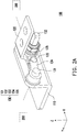
- FIGs. 2A and 2B are schematic views illustrating a hinge module of FIG. 1 from different viewing angles.
- a Cartesian (X-Y-Z) coordinate system is provided to more easily describe the components.
- a portable electronic device 10 includes a first device body 200, a second device body 300, and a hinge module 100 connected with the first device body 200 and the second device body 300.
- the first device body 200 and the second device body 300 are relatively rotatable with each other through the hinge module 100 to be opened or closed.
- the hinge module 100 includes a first bracket 110, a second bracket 120, a first rotating shaft 131, a second rotating shaft 133, and a linking rod 134.
- the first rotating shaft 131 is disposed on the first bracket 110
- the second rotating shaft 133 is disposed on the second bracket 120
- the first bracket 110 is assembled to the first device body 200
- the second bracket 120 is assembled to the second device body 300.
- FIGs. 2A and 2B are schematic views illustrating a hinge module of FIG. 1 from different viewing angles.
- the first bracket 110 includes a bottom plate 111 and a standing plate 112.
- the bottom plate 111 is located on the X-Y plane and assembled to the first device body 200
- the standing plate 112 is located on the X-Z plane and has a track 112a and a positioning hole 112b.
- the first rotating shaft 131 has a positioning part 131b, a pressing part 131a, and a shaft part 131c.
- the positioning part 131b is engaged with the positioning hole 112b and positioned on the X-Z plane, and the first rotating shaft 131 abuts against the standing plate 112 along Y-axis through the pressing part 131a being pressed against the standing plate 112.
- the linking rod 134 includes a first end 134a and a second end 134b which are opposite to each other and respectively pivot holes. The first end 134a is pivoted to the shaft part 131c of the first rotating shaft 131.
- the second racket 120 includes a bottom plate 121 and an extending part 122 standing below the bottom plate 121.
- a pivot hole 122b and a shaft hole 122a are disposed on the extending part 122.
- the second rotating shaft 133 has a moving part 133b, a pressing part 133c, and a shaft part 133a.
- the shaft part 133a penetrates through the shaft hole 122a.
- the extending part 122 is considered as being located on the X-Z plane, and the shaft direction (Y-axis direction) of the second rotating shaft 133 is orthogonal to the X-Z plane.
- the moving part 133b is movably and pivotably coupled to the track 112a of the first bracket 110, and the pressing part 133c abuts against the standing plate 112 of the first bracket 110 along Y-axis.
- the linking rod 134 is arranged as a coupling structure and pivoted to the pivot hole 122b of the extending part 122 through a connecting assembly 132 (including components 132a and 132b riveted to each other).
- the extending part 122 is substantially pivotably sandwiched in the coupling structure.
- the hinge module 100 further includes a torque assembly 135 including a pressing member 135a, torque members 135b and 135c, and a locking member 135d.
- a torque assembly 135 including a pressing member 135a, torque members 135b and 135c, and a locking member 135d.
- FIGs. 4A to 4D are side views illustrating a hinge module in different states.
- the first rotating shaft 131, the second rotating shaft 133, the connecting assembly 132, the linking rod 134, and the torque assembly 135 of the embodiment form a torque linkage mechanism 130. Since the shaft direction of the first rotating shaft 131 and the shaft direction of the second rotating shaft 133 are parallel to each other, the torque linkage mechanism 130 substantially carries out a linkage movement on the same plane (X-Z plane), as shown in FIG. 4A .
- FIG. 4A shows a state where the first device body 200 and the second device body 300 are folded and closed with respect to each other. In the state, the distance between the second rotating shaft 133 and the first rotating shaft 131 has the maximum value.
- the first device body 200 is pivotally rotated and expanded relative to the second device body 300.
- the second device body 300 is rotated in the clockwise direction with the first device body 200 serving as the reference.
- the first rotating shaft 131 is rotated in the counter-clockwise direction
- the second rotating shaft 133 is rotated in the clockwise direction
- the linking rod 134 is rotated in the counter-clockwise direction while simultaneously driving the second rotating shaft 133 to slide along the track 112a toward the negative X-axis direction, so as to gradually move toward the first rotating shaft 131 located at one end of the track 112a until the second rotating shaft 133 is close to the first rotating shaft 131 and the distance therebetween has the minimum value, as shown in FIG. 4D .
- the first device body and the second device body can be moved close to or away from each other through the corresponding relationship among the first rotating shaft, the second rotating shaft, and the linking rod of the hinge module when the first device body and the second device body are rotated relatively.
- the hinge module forms a configuration similar to a linkage mechanism.
- the second rotating shaft can be moved close to or away from the first rotating shaft when the second bracket is rotated relative to the first bracket.
- the mechanical interference between the device bodies due to limitation of a fixed-type hinge or a fixed distance between rotating shafts can be avoided, and the device bodies can be opened or closed smoothly through rotation.
Landscapes
- Engineering & Computer Science (AREA)
- Computer Hardware Design (AREA)
- Theoretical Computer Science (AREA)
- Physics & Mathematics (AREA)
- Human Computer Interaction (AREA)
- General Engineering & Computer Science (AREA)
- General Physics & Mathematics (AREA)
- Mathematical Physics (AREA)
- Telephone Set Structure (AREA)
- Pivots And Pivotal Connections (AREA)
Abstract
Description
- The disclosure relates to a hinge module and a portable electronic device.
- Portable computing devices, such as palmtop computers, portable computers, notebook computers, and personal digital assistants (PDAs) have become more and more popular. In general, a portable electronic device includes a base and a display assembly configured for the display of the base to comply with user operation and viewing purposes. In particular, as touch display technology advances through time, for portable computers, touch screens have gradually become the basic equipment.
- In general, to provide the user with a favorable visual effect as well as designing notebook computers to be lighter, thinner, more compact, and smaller, pursuing a higher screen-to-body ratio or a slim bezel has now become the trend in notebook computer design. Accordingly, the hinge of notebook computers needs to adopt a sunken design to cope with such needs. In other words, the hinge is designed to generate a motion of moving downward relative to the device body while simultaneously rotating the device body as well as moving the screen toward the device body where the system is located.
- However, limited by the rotating radius of the hinge, if the above needs are to be coped with, interference between device bodies may easily occur during the rotating process, making it difficult to achieve a favorable effect.
- Embodiments of the disclosure provide a hinge module and a portable electronic device having a flexible hinge so that device bodies of the portable electronic device are relatively movable during a rotating process.
- A hinge module according to an embodiment of the disclosure includes a first bracket, a first rotating shaft, a connecting rod, a second bracket, and a second rotating shaft. The first rotating shaft is disposed on the first bracket. The linking rod has a first end and a second end opposite to each other. The first end is pivoted to the first rotating shaft. A second rotating shaft is disposed on the second bracket and movably and pivotably connected to the first bracket. The second end of the linking rod is pivoted to the second bracket. In a process where the first bracket and the second bracket are rotated relatively, the first rotating shaft and the second rotating shaft are moved close to or away from each other.
- A portable electronic device according to an embodiment of the disclosure includes a first device body, a first rotating shaft, a second device body, a second rotating shaft, a first bracket, a second bracket, and a connecting rod. The first rotating shaft is disposed on the first bracket. The linking rod has a first end and a second end opposite to each other. The first end is pivoted to the first rotating shaft. A second rotating shaft is disposed on the second bracket and movably and pivotably connected to the first bracket. The second end of the linking rod is pivoted to the second bracket. In a process where the first device body and the second device body are rotated relatively, the first bracket and the second bracket are rotated relatively following the first device body and the second device body, and the first rotating shaft and the second rotating shaft are moved close to or away from each other.
- Based on the above, by disposing the hinge structure in the portable electronic device, the first device body and the second device body can be moved close to or away from each other through the corresponding relationship among the first rotating shaft, the second rotating shaft, and the linking rod of the hinge module when the first device body and the second device body are rotated relatively. In other words, the hinge module forms a configuration similar to a linkage mechanism. In this way, the second rotating shaft can be moved close to or away from the first rotating shaft when the second bracket is rotated relative to the first bracket. Accordingly, in the process where the first device body is rotated relative to the second device body to be opened or closed, the mechanical interference between the device bodies due to limitation of a fixed-type hinge or a fixed distance between rotating shafts can be avoided, and the device bodies can be opened or closed smoothly through rotation.
- To make the above features and advantages of the disclosure more comprehensible, embodiments accompanied with drawings are described in detail as follows.
- The accompanying drawings are included to provide a further understanding of the disclosure, and are incorporated in and constitute a part of this specification. The drawings illustrate embodiments of the disclosure and, together with the description, serve to explain the principles of the disclosure.
-
FIG. 1 is a schematic view illustrating a portable electronic device according to an embodiment of the disclosure. -
FIGs. 2A and2B are schematic views illustrating a hinge module ofFIG. 1 from different viewing angles. -
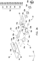
FIGs. 3A and3B are exploded views illustrating a hinge module from different viewing angles. -
FIGs. 4A to 4D are side views illustrating a hinge module in different states. - Reference will now be made in detail to the present preferred embodiments of the disclosure, examples of which are illustrated in the accompanying drawings. Wherever possible, the same reference numbers are used in the drawings and the description to refer to the same or like parts.
-
FIG. 1 is a schematic view illustrating a portable electronic device according to an embodiment of the disclosure.FIGs. 2A and2B are schematic views illustrating a hinge module ofFIG. 1 from different viewing angles. Here, a Cartesian (X-Y-Z) coordinate system is provided to more easily describe the components. Referring toFIGs. 1 ,2A , and2B , in the embodiment, a portable electronic device 10 includes afirst device body 200, asecond device body 300, and ahinge module 100 connected with thefirst device body 200 and thesecond device body 300. Thefirst device body 200 and thesecond device body 300 are relatively rotatable with each other through thehinge module 100 to be opened or closed. Thehinge module 100 includes afirst bracket 110, asecond bracket 120, a first rotatingshaft 131, a second rotatingshaft 133, and a linkingrod 134. The first rotatingshaft 131 is disposed on thefirst bracket 110, the second rotatingshaft 133 is disposed on thesecond bracket 120, thefirst bracket 110 is assembled to thefirst device body 200, and thesecond bracket 120 is assembled to thesecond device body 300. -
FIGs. 2A and2B are schematic views illustrating a hinge module ofFIG. 1 from different viewing angles. Referring toFIGs. 2A and2B , in the embodiment, thefirst bracket 110 includes abottom plate 111 and a standingplate 112. Thebottom plate 111 is located on the X-Y plane and assembled to thefirst device body 200, and the standingplate 112 is located on the X-Z plane and has atrack 112a and apositioning hole 112b. The first rotatingshaft 131 has apositioning part 131b, apressing part 131a, and ashaft part 131c. The positioningpart 131b is engaged with thepositioning hole 112b and positioned on the X-Z plane, and the first rotatingshaft 131 abuts against the standingplate 112 along Y-axis through thepressing part 131a being pressed against thestanding plate 112. The linkingrod 134 includes afirst end 134a and asecond end 134b which are opposite to each other and respectively pivot holes. Thefirst end 134a is pivoted to theshaft part 131c of the first rotatingshaft 131. - The
second racket 120 includes abottom plate 121 and an extendingpart 122 standing below thebottom plate 121. Apivot hole 122b and ashaft hole 122a are disposed on the extendingpart 122. The second rotatingshaft 133 has a movingpart 133b, apressing part 133c, and ashaft part 133a. Theshaft part 133a penetrates through theshaft hole 122a. In addition, in the embodiment, the extendingpart 122 is considered as being located on the X-Z plane, and the shaft direction (Y-axis direction) of the secondrotating shaft 133 is orthogonal to the X-Z plane. - Moreover, the moving
part 133b is movably and pivotably coupled to thetrack 112a of thefirst bracket 110, and thepressing part 133c abuts against the standingplate 112 of thefirst bracket 110 along Y-axis. At thesecond end 134b, the linkingrod 134 is arranged as a coupling structure and pivoted to thepivot hole 122b of the extendingpart 122 through a connecting assembly 132 (includingcomponents part 122 is substantially pivotably sandwiched in the coupling structure. - Moreover, the
hinge module 100 further includes atorque assembly 135 including apressing member 135a,torque members member 135d. After theshaft part 133a of the secondrotating shaft 133 penetrates through theshaft hole 122a, the pressingmember 135a, thetorque members member 135d are sequentially disposed on theshaft part 133a of the secondrotating shaft 133 and abut against the extendingpart 122 of thesecond bracket 120. Accordingly, a torque force is provided between thesecond bracket 120 and the secondrotating shaft 133 by thetorque assembly 134 through the friction force which thetorque assembly 135 can generate when thesecond bracket 120 and the secondrotating shaft 133 are relatively pivotally rotated on Y-axis. -
FIGs. 4A to 4D are side views illustrating a hinge module in different states. Referring toFIG. 4A , based on the configuration above, the firstrotating shaft 131, the secondrotating shaft 133, the connectingassembly 132, the linkingrod 134, and thetorque assembly 135 of the embodiment form atorque linkage mechanism 130. Since the shaft direction of the firstrotating shaft 131 and the shaft direction of the secondrotating shaft 133 are parallel to each other, thetorque linkage mechanism 130 substantially carries out a linkage movement on the same plane (X-Z plane), as shown inFIG. 4A . Here, like the illustration ofFIG. 1 ,FIG. 4A shows a state where thefirst device body 200 and thesecond device body 300 are folded and closed with respect to each other. In the state, the distance between the secondrotating shaft 133 and the firstrotating shaft 131 has the maximum value. - Then, referring to
FIGs. 4B to 4D , thefirst device body 200 is pivotally rotated and expanded relative to thesecond device body 300. In other words, thesecond device body 300 is rotated in the clockwise direction with thefirst device body 200 serving as the reference. At this time, due to the connection relationship among the components of thetorque linkage mechanism 130, the firstrotating shaft 131 is rotated in the counter-clockwise direction, the secondrotating shaft 133 is rotated in the clockwise direction, and the linkingrod 134 is rotated in the counter-clockwise direction while simultaneously driving the secondrotating shaft 133 to slide along thetrack 112a toward the negative X-axis direction, so as to gradually move toward the firstrotating shaft 131 located at one end of thetrack 112a until the secondrotating shaft 133 is close to the firstrotating shaft 131 and the distance therebetween has the minimum value, as shown inFIG. 4D . - Comparatively, when the
first device body 200 and thesecond device body 300 are relatively rotated and closed from the expanded state shown inFIG. 4D , the state is sequentially changed from the state shown inFIG. 4D to the state shown inFIG. 4A . That is, the secondrotating shaft 133 is moved toward the positive X-axis direction along thetrack 112a due to the rotation of thesecond bracket 120, so as to move away from the firstrotating shaft 131 until the secondrotating shaft 133 is restored to the position shown inFIG. 4A . - In view of the foregoing, in the embodiment of the disclosure, by disposing the hinge structure in the portable electronic device, the first device body and the second device body can be moved close to or away from each other through the corresponding relationship among the first rotating shaft, the second rotating shaft, and the linking rod of the hinge module when the first device body and the second device body are rotated relatively. In other words, the hinge module forms a configuration similar to a linkage mechanism. In this way, the second rotating shaft can be moved close to or away from the first rotating shaft when the second bracket is rotated relative to the first bracket. Accordingly, in the process where the first device body is rotated relative to the second device body to be opened or closed, the mechanical interference between the device bodies due to limitation of a fixed-type hinge or a fixed distance between rotating shafts can be avoided, and the device bodies can be opened or closed smoothly through rotation.
Claims (15)
- A hinge module (100), adapted for a portable electronic device, the hinge module (100) comprising:a first bracket (110);a first rotating shaft (131), disposed on the first bracket (110);a linking rod (134), having a first end (134a) and a second end (134b) opposite to each other, wherein the first end (134a) is pivoted to the first rotating shaft (131);a second bracket (120); anda second rotating shaft (133), disposed on the second bracket (120), wherein the second rotating shaft (133) is movably and pivotably connected to the first bracket (110), the second end (134b) of the linking rod (134) is pivoted to the second bracket (120), and in a process where the first bracket (110) and the second bracket (120) are rotated relatively, the first rotating shaft (131) and the second rotating shaft (133) are moved close to or away from each other.
- The hinge module (100) as claimed in claim 1, wherein the first bracket (110) further comprises a track (112a), the second rotating shaft (133) is movably and pivotably coupled to the track (112a), the first rotating shaft (131) is adjacent to an end of the track (112a), and the second rotating shaft (133) is moved close to or away from the first rotating shaft (131) along the track (112a).
- The hinge module (100) as claimed in claim 1, wherein the second bracket (120) has an extending part (122), the second rotating shaft (133) penetrates through the extending part (122), and a shaft direction of the second rotating shaft (133) is orthogonal to a plane where the extending part (122) is located.
- The hinge module (100) as claimed in claim 3, wherein the linking rod (134) is arranged as a coupling structure at the second end (134b), and the extending part (122) is pivotably engaged in the coupling structure.
- The hinge module (100) as claimed in claim 1, wherein a shaft direction of the first rotating shaft (131) is parallel to a shaft direction of the second rotating shaft (133).
- The hinge module (100) as claimed in claim 1, further comprising a torque assembly (135) disposed on the second rotating shaft (133) and pressed against the second bracket (120).
- The hinge module (100) as claimed in claim 1, wherein a rotating direction of the first rotating shaft (131) is opposite to a rotating direction of the second rotating shaft (133).
- A portable electronic device (10), comprising:a first device body (200);a first bracket (110), assembled to the first device body (200);a first rotating shaft (131), disposed on the first bracket (110);a linking rod (134), having a first end (134a) and a second end (134b) opposite to each other, wherein the first end (134a) is pivoted to the first rotating shaft (131);a second device body (300); anda second bracket (120), assembled to the second device body (300);a second rotating shaft (133), disposed on the second bracket (120), wherein the second rotating shaft (133) is movably and pivotably connected to the first bracket (110), the second end (134b) of the linking rod (134) is pivoted to the second bracket (120), and in a process where the first device body (200) and the second device body (300) are rotated relatively, the first bracket (110) and the second bracket (120) are rotated relatively following the first device body (200) and the second device body (300), and the first rotating shaft (131) and the second rotating shaft (133) are moved close to or away from each other.
- The portable electronic device (10) as claimed in claim 8, wherein the first bracket (110) further comprises a track (112a), the second rotating shaft (133) is pivotably coupled to the track (112a), the first rotating shaft (131) is adjacent to an end of the track (112a), and the second rotating shaft (133) is moved close to or away from the first rotating shaft (131) along the track (112a).
- The portable electronic device (10) as claimed in claim 8, wherein the second bracket (120) has an extending part (122), the second rotating shaft (133) penetrates through the extending part (122), and a shaft direction of the second rotating shaft (133) is orthogonal to a plane where the extending part (122) is located.
- The portable electronic device (10) as claimed in claim 10, wherein the linking rod (134) is arranged as a coupling structure at the second end (134b), and the extending part (122) is pivotably engaged in the coupling structure.
- The portable electronic device (10) as claimed in claim 8, wherein a shaft direction of the first rotating shaft (131) is parallel to a shaft direction of the second rotating shaft (133).
- The portable electronic device (10) as claimed in claim 8, further comprising a torque assembly (135) disposed on the second rotating shaft (133).
- The portable electronic device (10) as claimed in claim 8, wherein a rotating direction of the first rotating shaft (131) is opposite to a rotating direction of the second rotating shaft (133).
- The portable electronic device (10) as claimed in claim 8, wherein when the first device body (200) and the second device body (300) are folded and closed with respect to each other, a distance between the first rotating shaft (131) and the second rotating shaft (133) has a maximum value, and in a process where the first device body (200) and the second device body (300) are expanded with respect to each other, the second rotating shaft (133) is moved to the first rotating shaft (131).
Applications Claiming Priority (1)
| Application Number | Priority Date | Filing Date | Title |
|---|---|---|---|
| TW108133419A TWI715198B (en) | 2019-09-17 | 2019-09-17 | Hinge module and portable electronic device |
Publications (2)
| Publication Number | Publication Date |
|---|---|
| EP3796126A1 true EP3796126A1 (en) | 2021-03-24 |
| EP3796126B1 EP3796126B1 (en) | 2023-10-25 |
Family
ID=70977834
Family Applications (1)
| Application Number | Title | Priority Date | Filing Date |
|---|---|---|---|
| EP20178308.1A Active EP3796126B1 (en) | 2019-09-17 | 2020-06-04 | Hinge module and portable electronic device |
Country Status (3)
| Country | Link |
|---|---|
| US (1) | US20210081005A1 (en) |
| EP (1) | EP3796126B1 (en) |
| TW (1) | TWI715198B (en) |
Cited By (1)
| Publication number | Priority date | Publication date | Assignee | Title |
|---|---|---|---|---|
| TWI839897B (en) * | 2022-10-17 | 2024-04-21 | 富世達股份有限公司 | Displaceable rotating shaft and foldable device provided with the rotating shaft |
Families Citing this family (3)
| Publication number | Priority date | Publication date | Assignee | Title |
|---|---|---|---|---|
| KR20240012347A (en) * | 2021-05-21 | 2024-01-29 | 엘지전자 주식회사 | Portable electronic device containing a hinge module |
| US11847000B2 (en) * | 2021-12-30 | 2023-12-19 | Acer Incorporated | Portable electronic device |
| KR102766570B1 (en) * | 2023-12-18 | 2025-02-12 | (주)플렉시고 | Folding mechanism for stress free |
Citations (2)
| Publication number | Priority date | Publication date | Assignee | Title |
|---|---|---|---|---|
| US20160320811A1 (en) * | 2015-05-01 | 2016-11-03 | Sinher Technology Inc. | Thin hinge |
| US20190171255A1 (en) * | 2017-12-01 | 2019-06-06 | Acer Incorporated | Hinge module and electronic device using the same |
Family Cites Families (6)
| Publication number | Priority date | Publication date | Assignee | Title |
|---|---|---|---|---|
| CN202326679U (en) * | 2011-11-25 | 2012-07-11 | 宏碁股份有限公司 | Folding electronic device and link type pivot device |
| TWM443091U (en) * | 2012-08-09 | 2012-12-11 | Lian Hong Art Co Ltd | Slide-cover electronic equipment invisible transmission mechanism |
| TWM523132U (en) * | 2016-01-22 | 2016-06-01 | 飛捷科技股份有限公司 | Electronic device with multi-directional rotation function |
| TWI633413B (en) * | 2016-12-15 | 2018-08-21 | 宏碁股份有限公司 | Portable electronic device |
| CN207018340U (en) * | 2017-06-13 | 2018-02-16 | 富世达股份有限公司 | Hinge and foldable electronic device with the hinge |
| CN209294695U (en) * | 2019-01-03 | 2019-08-23 | 智卓(深圳)电子科技有限公司 | Electronic device clamps bracket |
-
2019
- 2019-09-17 TW TW108133419A patent/TWI715198B/en active
-
2020
- 2020-02-25 US US16/799,852 patent/US20210081005A1/en not_active Abandoned
- 2020-06-04 EP EP20178308.1A patent/EP3796126B1/en active Active
Patent Citations (2)
| Publication number | Priority date | Publication date | Assignee | Title |
|---|---|---|---|---|
| US20160320811A1 (en) * | 2015-05-01 | 2016-11-03 | Sinher Technology Inc. | Thin hinge |
| US20190171255A1 (en) * | 2017-12-01 | 2019-06-06 | Acer Incorporated | Hinge module and electronic device using the same |
Cited By (1)
| Publication number | Priority date | Publication date | Assignee | Title |
|---|---|---|---|---|
| TWI839897B (en) * | 2022-10-17 | 2024-04-21 | 富世達股份有限公司 | Displaceable rotating shaft and foldable device provided with the rotating shaft |
Also Published As
| Publication number | Publication date |
|---|---|
| EP3796126B1 (en) | 2023-10-25 |
| TWI715198B (en) | 2021-01-01 |
| TW202113247A (en) | 2021-04-01 |
| US20210081005A1 (en) | 2021-03-18 |
Similar Documents
| Publication | Publication Date | Title |
|---|---|---|
| US11281261B2 (en) | Hinge module and electronic device using the same | |
| EP3796126B1 (en) | Hinge module and portable electronic device | |
| CN113202857B (en) | Hinge, flexible display panel and electronic device | |
| US11762430B2 (en) | Structure of hinge for foldable electronic device, and electronic device including the same | |
| US7599178B2 (en) | Connection assembly for connecting bodies, and portable electronic apparatus and base using the same | |
| JP5333054B2 (en) | Electronics | |
| US11262793B2 (en) | Folding-type electronic device | |
| US9122454B2 (en) | Hinge module and electronic device | |
| US11782487B2 (en) | Foldable electronic device | |
| CN215890763U (en) | Hinge, flexible display panel and electronic device | |
| TWI774302B (en) | Elevating double-axis hinge and terminal machine using the elevating double-axis hinge | |
| CN119435562A (en) | A swing rod mechanism, connecting assembly and electronic equipment | |
| JPWO2021210075A5 (en) | ||
| CN117128233B (en) | Damping mechanism, folding hinge and electronic equipment | |
| US11609615B2 (en) | Portable electronic device | |
| TW202103541A (en) | Linkage mechanism and electronic device | |
| CN104635856B (en) | Electronic device | |
| US11579659B2 (en) | Electronic device | |
| US7085129B2 (en) | Support apparatus | |
| CN113138626B (en) | Portable electronic device | |
| KR19980041663A (en) | Ergonomic keyboard for portable computer and its operation and manufacturing method | |
| CN107608450B (en) | Connecting device and electronic equipment | |
| TWI764155B (en) | Foldable electronic device | |
| TWI822003B (en) | Portable electronic device | |
| CN112578848A (en) | Rotating shaft module and portable electronic device |
Legal Events
| Date | Code | Title | Description |
|---|---|---|---|
| PUAI | Public reference made under article 153(3) epc to a published international application that has entered the european phase |
Free format text: ORIGINAL CODE: 0009012 |
|
| STAA | Information on the status of an ep patent application or granted ep patent |
Free format text: STATUS: THE APPLICATION HAS BEEN PUBLISHED |
|
| AK | Designated contracting states |
Kind code of ref document: A1 Designated state(s): AL AT BE BG CH CY CZ DE DK EE ES FI FR GB GR HR HU IE IS IT LI LT LU LV MC MK MT NL NO PL PT RO RS SE SI SK SM TR |
|
| AX | Request for extension of the european patent |
Extension state: BA ME |
|
| STAA | Information on the status of an ep patent application or granted ep patent |
Free format text: STATUS: REQUEST FOR EXAMINATION WAS MADE |
|
| 17P | Request for examination filed |
Effective date: 20210422 |
|
| RBV | Designated contracting states (corrected) |
Designated state(s): AL AT BE BG CH CY CZ DE DK EE ES FI FR GB GR HR HU IE IS IT LI LT LU LV MC MK MT NL NO PL PT RO RS SE SI SK SM TR |
|
| STAA | Information on the status of an ep patent application or granted ep patent |
Free format text: STATUS: EXAMINATION IS IN PROGRESS |
|
| 17Q | First examination report despatched |
Effective date: 20220729 |
|
| GRAP | Despatch of communication of intention to grant a patent |
Free format text: ORIGINAL CODE: EPIDOSNIGR1 |
|
| STAA | Information on the status of an ep patent application or granted ep patent |
Free format text: STATUS: GRANT OF PATENT IS INTENDED |
|
| INTG | Intention to grant announced |
Effective date: 20230606 |
|
| GRAS | Grant fee paid |
Free format text: ORIGINAL CODE: EPIDOSNIGR3 |
|
| GRAA | (expected) grant |
Free format text: ORIGINAL CODE: 0009210 |
|
| STAA | Information on the status of an ep patent application or granted ep patent |
Free format text: STATUS: THE PATENT HAS BEEN GRANTED |
|
| AK | Designated contracting states |
Kind code of ref document: B1 Designated state(s): AL AT BE BG CH CY CZ DE DK EE ES FI FR GB GR HR HU IE IS IT LI LT LU LV MC MK MT NL NO PL PT RO RS SE SI SK SM TR |
|
| REG | Reference to a national code |
Ref country code: GB Ref legal event code: FG4D |
|
| REG | Reference to a national code |
Ref country code: CH Ref legal event code: EP |
|
| REG | Reference to a national code |
Ref country code: DE Ref legal event code: R096 Ref document number: 602020019697 Country of ref document: DE |
|
| REG | Reference to a national code |
Ref country code: IE Ref legal event code: FG4D |
|
| REG | Reference to a national code |
Ref country code: LT Ref legal event code: MG9D |
|
| REG | Reference to a national code |
Ref country code: NL Ref legal event code: MP Effective date: 20231025 |
|
| REG | Reference to a national code |
Ref country code: AT Ref legal event code: MK05 Ref document number: 1625318 Country of ref document: AT Kind code of ref document: T Effective date: 20231025 |
|
| PG25 | Lapsed in a contracting state [announced via postgrant information from national office to epo] |
Ref country code: NL Free format text: LAPSE BECAUSE OF FAILURE TO SUBMIT A TRANSLATION OF THE DESCRIPTION OR TO PAY THE FEE WITHIN THE PRESCRIBED TIME-LIMIT Effective date: 20231025 |
|
| PG25 | Lapsed in a contracting state [announced via postgrant information from national office to epo] |
Ref country code: GR Free format text: LAPSE BECAUSE OF FAILURE TO SUBMIT A TRANSLATION OF THE DESCRIPTION OR TO PAY THE FEE WITHIN THE PRESCRIBED TIME-LIMIT Effective date: 20240126 |
|
| PG25 | Lapsed in a contracting state [announced via postgrant information from national office to epo] |
Ref country code: IS Free format text: LAPSE BECAUSE OF FAILURE TO SUBMIT A TRANSLATION OF THE DESCRIPTION OR TO PAY THE FEE WITHIN THE PRESCRIBED TIME-LIMIT Effective date: 20240225 |
|
| PG25 | Lapsed in a contracting state [announced via postgrant information from national office to epo] |
Ref country code: LT Free format text: LAPSE BECAUSE OF FAILURE TO SUBMIT A TRANSLATION OF THE DESCRIPTION OR TO PAY THE FEE WITHIN THE PRESCRIBED TIME-LIMIT Effective date: 20231025 |
|
| PG25 | Lapsed in a contracting state [announced via postgrant information from national office to epo] |
Ref country code: AT Free format text: LAPSE BECAUSE OF FAILURE TO SUBMIT A TRANSLATION OF THE DESCRIPTION OR TO PAY THE FEE WITHIN THE PRESCRIBED TIME-LIMIT Effective date: 20231025 |
|
| PG25 | Lapsed in a contracting state [announced via postgrant information from national office to epo] |
Ref country code: ES Free format text: LAPSE BECAUSE OF FAILURE TO SUBMIT A TRANSLATION OF THE DESCRIPTION OR TO PAY THE FEE WITHIN THE PRESCRIBED TIME-LIMIT Effective date: 20231025 |
|
| PG25 | Lapsed in a contracting state [announced via postgrant information from national office to epo] |
Ref country code: LT Free format text: LAPSE BECAUSE OF FAILURE TO SUBMIT A TRANSLATION OF THE DESCRIPTION OR TO PAY THE FEE WITHIN THE PRESCRIBED TIME-LIMIT Effective date: 20231025 Ref country code: IS Free format text: LAPSE BECAUSE OF FAILURE TO SUBMIT A TRANSLATION OF THE DESCRIPTION OR TO PAY THE FEE WITHIN THE PRESCRIBED TIME-LIMIT Effective date: 20240225 Ref country code: GR Free format text: LAPSE BECAUSE OF FAILURE TO SUBMIT A TRANSLATION OF THE DESCRIPTION OR TO PAY THE FEE WITHIN THE PRESCRIBED TIME-LIMIT Effective date: 20240126 Ref country code: ES Free format text: LAPSE BECAUSE OF FAILURE TO SUBMIT A TRANSLATION OF THE DESCRIPTION OR TO PAY THE FEE WITHIN THE PRESCRIBED TIME-LIMIT Effective date: 20231025 Ref country code: BG Free format text: LAPSE BECAUSE OF FAILURE TO SUBMIT A TRANSLATION OF THE DESCRIPTION OR TO PAY THE FEE WITHIN THE PRESCRIBED TIME-LIMIT Effective date: 20240125 Ref country code: AT Free format text: LAPSE BECAUSE OF FAILURE TO SUBMIT A TRANSLATION OF THE DESCRIPTION OR TO PAY THE FEE WITHIN THE PRESCRIBED TIME-LIMIT Effective date: 20231025 Ref country code: PT Free format text: LAPSE BECAUSE OF FAILURE TO SUBMIT A TRANSLATION OF THE DESCRIPTION OR TO PAY THE FEE WITHIN THE PRESCRIBED TIME-LIMIT Effective date: 20240226 |
|
| PG25 | Lapsed in a contracting state [announced via postgrant information from national office to epo] |
Ref country code: SE Free format text: LAPSE BECAUSE OF FAILURE TO SUBMIT A TRANSLATION OF THE DESCRIPTION OR TO PAY THE FEE WITHIN THE PRESCRIBED TIME-LIMIT Effective date: 20231025 Ref country code: RS Free format text: LAPSE BECAUSE OF FAILURE TO SUBMIT A TRANSLATION OF THE DESCRIPTION OR TO PAY THE FEE WITHIN THE PRESCRIBED TIME-LIMIT Effective date: 20231025 Ref country code: PL Free format text: LAPSE BECAUSE OF FAILURE TO SUBMIT A TRANSLATION OF THE DESCRIPTION OR TO PAY THE FEE WITHIN THE PRESCRIBED TIME-LIMIT Effective date: 20231025 Ref country code: NO Free format text: LAPSE BECAUSE OF FAILURE TO SUBMIT A TRANSLATION OF THE DESCRIPTION OR TO PAY THE FEE WITHIN THE PRESCRIBED TIME-LIMIT Effective date: 20240125 Ref country code: LV Free format text: LAPSE BECAUSE OF FAILURE TO SUBMIT A TRANSLATION OF THE DESCRIPTION OR TO PAY THE FEE WITHIN THE PRESCRIBED TIME-LIMIT Effective date: 20231025 Ref country code: HR Free format text: LAPSE BECAUSE OF FAILURE TO SUBMIT A TRANSLATION OF THE DESCRIPTION OR TO PAY THE FEE WITHIN THE PRESCRIBED TIME-LIMIT Effective date: 20231025 |
|
| PG25 | Lapsed in a contracting state [announced via postgrant information from national office to epo] |
Ref country code: DK Free format text: LAPSE BECAUSE OF FAILURE TO SUBMIT A TRANSLATION OF THE DESCRIPTION OR TO PAY THE FEE WITHIN THE PRESCRIBED TIME-LIMIT Effective date: 20231025 |
|
| PG25 | Lapsed in a contracting state [announced via postgrant information from national office to epo] |
Ref country code: CZ Free format text: LAPSE BECAUSE OF FAILURE TO SUBMIT A TRANSLATION OF THE DESCRIPTION OR TO PAY THE FEE WITHIN THE PRESCRIBED TIME-LIMIT Effective date: 20231025 |
|
| REG | Reference to a national code |
Ref country code: DE Ref legal event code: R097 Ref document number: 602020019697 Country of ref document: DE |
|
| PG25 | Lapsed in a contracting state [announced via postgrant information from national office to epo] |
Ref country code: SK Free format text: LAPSE BECAUSE OF FAILURE TO SUBMIT A TRANSLATION OF THE DESCRIPTION OR TO PAY THE FEE WITHIN THE PRESCRIBED TIME-LIMIT Effective date: 20231025 |
|
| PG25 | Lapsed in a contracting state [announced via postgrant information from national office to epo] |
Ref country code: SM Free format text: LAPSE BECAUSE OF FAILURE TO SUBMIT A TRANSLATION OF THE DESCRIPTION OR TO PAY THE FEE WITHIN THE PRESCRIBED TIME-LIMIT Effective date: 20231025 Ref country code: SK Free format text: LAPSE BECAUSE OF FAILURE TO SUBMIT A TRANSLATION OF THE DESCRIPTION OR TO PAY THE FEE WITHIN THE PRESCRIBED TIME-LIMIT Effective date: 20231025 Ref country code: RO Free format text: LAPSE BECAUSE OF FAILURE TO SUBMIT A TRANSLATION OF THE DESCRIPTION OR TO PAY THE FEE WITHIN THE PRESCRIBED TIME-LIMIT Effective date: 20231025 Ref country code: IT Free format text: LAPSE BECAUSE OF FAILURE TO SUBMIT A TRANSLATION OF THE DESCRIPTION OR TO PAY THE FEE WITHIN THE PRESCRIBED TIME-LIMIT Effective date: 20231025 Ref country code: EE Free format text: LAPSE BECAUSE OF FAILURE TO SUBMIT A TRANSLATION OF THE DESCRIPTION OR TO PAY THE FEE WITHIN THE PRESCRIBED TIME-LIMIT Effective date: 20231025 Ref country code: DK Free format text: LAPSE BECAUSE OF FAILURE TO SUBMIT A TRANSLATION OF THE DESCRIPTION OR TO PAY THE FEE WITHIN THE PRESCRIBED TIME-LIMIT Effective date: 20231025 Ref country code: CZ Free format text: LAPSE BECAUSE OF FAILURE TO SUBMIT A TRANSLATION OF THE DESCRIPTION OR TO PAY THE FEE WITHIN THE PRESCRIBED TIME-LIMIT Effective date: 20231025 |
|
| PLBE | No opposition filed within time limit |
Free format text: ORIGINAL CODE: 0009261 |
|
| STAA | Information on the status of an ep patent application or granted ep patent |
Free format text: STATUS: NO OPPOSITION FILED WITHIN TIME LIMIT |
|
| 26N | No opposition filed |
Effective date: 20240726 |
|
| PG25 | Lapsed in a contracting state [announced via postgrant information from national office to epo] |
Ref country code: SI Free format text: LAPSE BECAUSE OF FAILURE TO SUBMIT A TRANSLATION OF THE DESCRIPTION OR TO PAY THE FEE WITHIN THE PRESCRIBED TIME-LIMIT Effective date: 20231025 |
|
| PG25 | Lapsed in a contracting state [announced via postgrant information from national office to epo] |
Ref country code: SI Free format text: LAPSE BECAUSE OF FAILURE TO SUBMIT A TRANSLATION OF THE DESCRIPTION OR TO PAY THE FEE WITHIN THE PRESCRIBED TIME-LIMIT Effective date: 20231025 |
|
| PG25 | Lapsed in a contracting state [announced via postgrant information from national office to epo] |
Ref country code: MC Free format text: LAPSE BECAUSE OF FAILURE TO SUBMIT A TRANSLATION OF THE DESCRIPTION OR TO PAY THE FEE WITHIN THE PRESCRIBED TIME-LIMIT Effective date: 20231025 |
|
| REG | Reference to a national code |
Ref country code: CH Ref legal event code: PL |
|
| PG25 | Lapsed in a contracting state [announced via postgrant information from national office to epo] |
Ref country code: LU Free format text: LAPSE BECAUSE OF NON-PAYMENT OF DUE FEES Effective date: 20240604 |
|
| PG25 | Lapsed in a contracting state [announced via postgrant information from national office to epo] |
Ref country code: IE Free format text: LAPSE BECAUSE OF NON-PAYMENT OF DUE FEES Effective date: 20240604 |
|
| PG25 | Lapsed in a contracting state [announced via postgrant information from national office to epo] |
Ref country code: CH Free format text: LAPSE BECAUSE OF NON-PAYMENT OF DUE FEES Effective date: 20240630 Ref country code: BE Free format text: LAPSE BECAUSE OF NON-PAYMENT OF DUE FEES Effective date: 20240630 |
|
| REG | Reference to a national code |
Ref country code: BE Ref legal event code: MM Effective date: 20240630 |
|
| PGFP | Annual fee paid to national office [announced via postgrant information from national office to epo] |
Ref country code: DE Payment date: 20250416 Year of fee payment: 6 |
|
| PGFP | Annual fee paid to national office [announced via postgrant information from national office to epo] |
Ref country code: GB Payment date: 20250410 Year of fee payment: 6 |
|
| PGFP | Annual fee paid to national office [announced via postgrant information from national office to epo] |
Ref country code: FR Payment date: 20250422 Year of fee payment: 6 |
|
| PG25 | Lapsed in a contracting state [announced via postgrant information from national office to epo] |
Ref country code: FI Free format text: LAPSE BECAUSE OF FAILURE TO SUBMIT A TRANSLATION OF THE DESCRIPTION OR TO PAY THE FEE WITHIN THE PRESCRIBED TIME-LIMIT Effective date: 20231025 |
|
| PG25 | Lapsed in a contracting state [announced via postgrant information from national office to epo] |
Ref country code: CY Free format text: LAPSE BECAUSE OF FAILURE TO SUBMIT A TRANSLATION OF THE DESCRIPTION OR TO PAY THE FEE WITHIN THE PRESCRIBED TIME-LIMIT; INVALID AB INITIO Effective date: 20200604 |
|
| PG25 | Lapsed in a contracting state [announced via postgrant information from national office to epo] |
Ref country code: HU Free format text: LAPSE BECAUSE OF FAILURE TO SUBMIT A TRANSLATION OF THE DESCRIPTION OR TO PAY THE FEE WITHIN THE PRESCRIBED TIME-LIMIT; INVALID AB INITIO Effective date: 20200604 |