EP3796059A1 - Storage tray for protecting optical fibers mechanically coupled to an optoelectronic device - Google Patents
Storage tray for protecting optical fibers mechanically coupled to an optoelectronic device Download PDFInfo
- Publication number
- EP3796059A1 EP3796059A1 EP19198765.0A EP19198765A EP3796059A1 EP 3796059 A1 EP3796059 A1 EP 3796059A1 EP 19198765 A EP19198765 A EP 19198765A EP 3796059 A1 EP3796059 A1 EP 3796059A1
- Authority
- EP
- European Patent Office
- Prior art keywords
- fiber
- storage tray
- optoelectronic device
- optical fibers
- storage
- Prior art date
- Legal status (The legal status is an assumption and is not a legal conclusion. Google has not performed a legal analysis and makes no representation as to the accuracy of the status listed.)
- Granted
Links
Images

Classifications
-
- G—PHYSICS
- G02—OPTICS
- G02B—OPTICAL ELEMENTS, SYSTEMS OR APPARATUS
- G02B6/00—Light guides; Structural details of arrangements comprising light guides and other optical elements, e.g. couplings
- G02B6/44—Mechanical structures for providing tensile strength and external protection for fibres, e.g. optical transmission cables
- G02B6/4439—Auxiliary devices
- G02B6/4471—Terminating devices ; Cable clamps
- G02B6/4478—Bending relief means
-
- G—PHYSICS
- G02—OPTICS
- G02B—OPTICAL ELEMENTS, SYSTEMS OR APPARATUS
- G02B6/00—Light guides; Structural details of arrangements comprising light guides and other optical elements, e.g. couplings
- G02B6/24—Coupling light guides
- G02B6/42—Coupling light guides with opto-electronic elements
- G02B6/4201—Packages, e.g. shape, construction, internal or external details
- G02B6/4256—Details of housings
- G02B6/426—Details of housings mounting, engaging or coupling of the package to a board, a frame or a panel
- G02B6/4261—Packages with mounting structures to be pluggable or detachable, e.g. having latches or rails
-
- G—PHYSICS
- G02—OPTICS
- G02B—OPTICAL ELEMENTS, SYSTEMS OR APPARATUS
- G02B6/00—Light guides; Structural details of arrangements comprising light guides and other optical elements, e.g. couplings
- G02B6/44—Mechanical structures for providing tensile strength and external protection for fibres, e.g. optical transmission cables
- G02B6/4439—Auxiliary devices
- G02B6/444—Systems or boxes with surplus lengths
-
- G—PHYSICS
- G02—OPTICS
- G02B—OPTICAL ELEMENTS, SYSTEMS OR APPARATUS
- G02B6/00—Light guides; Structural details of arrangements comprising light guides and other optical elements, e.g. couplings
- G02B6/44—Mechanical structures for providing tensile strength and external protection for fibres, e.g. optical transmission cables
- G02B6/4439—Auxiliary devices
- G02B6/444—Systems or boxes with surplus lengths
- G02B6/4441—Boxes
- G02B6/4448—Electro-optic
-
- G—PHYSICS
- G02—OPTICS
- G02B—OPTICAL ELEMENTS, SYSTEMS OR APPARATUS
- G02B6/00—Light guides; Structural details of arrangements comprising light guides and other optical elements, e.g. couplings
- G02B6/44—Mechanical structures for providing tensile strength and external protection for fibres, e.g. optical transmission cables
- G02B6/4439—Auxiliary devices
- G02B6/444—Systems or boxes with surplus lengths
- G02B6/4452—Distribution frames
- G02B6/44526—Panels or rackmounts covering a whole width of the frame or rack
-
- G—PHYSICS
- G02—OPTICS
- G02B—OPTICAL ELEMENTS, SYSTEMS OR APPARATUS
- G02B6/00—Light guides; Structural details of arrangements comprising light guides and other optical elements, e.g. couplings
- G02B6/24—Coupling light guides
- G02B6/42—Coupling light guides with opto-electronic elements
-
- G—PHYSICS
- G02—OPTICS
- G02B—OPTICAL ELEMENTS, SYSTEMS OR APPARATUS
- G02B6/00—Light guides; Structural details of arrangements comprising light guides and other optical elements, e.g. couplings
- G02B6/24—Coupling light guides
- G02B6/42—Coupling light guides with opto-electronic elements
- G02B6/4201—Packages, e.g. shape, construction, internal or external details
- G02B6/4274—Electrical aspects
- G02B6/4278—Electrical aspects related to pluggable or demountable opto-electronic or electronic elements
Definitions
- the present invention relates to a storage tray for protecting one or more optical fibers mechanically coupled to an optoelectronic device according to patent claim 1.
- the present invention further relates to an assembly according to patent claim 13 comprising a storage tray according to the present invention, and an optoelectronic device.
- Optical fibers connected to an optoelectronic device are components which are only stable to a certain extent. Optical fibers should e.g. not be bent beyond their minimum radius to prevent damage. However, such optoelectronic components are often subjected to a handling process at the manufacturer, during shipment to the customer, and all movements at the customer until completion of the implementation of the optoelectronic device into the final product.
- optical fibers are therefore wrapped around a spool for transportation and handling purposes.
- the wrapped fibers must be held in place under tension by a holding means, e.g. a clip, in order to prevent the fibers from unraveling.
- a holding means e.g. a clip
- the inventors of the present invention provide a storage tray for protecting one or more optical fibers mechanically coupled to an optoelectronic device according to patent claim 1.
- the storage tray according to the present invention is characterized in that it is configured to be capable of coupling with the optoelectronic device, and comprises a fiber storage portion which is configured to receive and store the one or more optical fibers. Further preferred embodiments are given in the dependent claims 2 to 12.
- the storage tray according to the invention enables the storage of optical fibers of different lengths of an optoelectronic device to be safely stored or transported, since the optical fibers are protected by the lateral walls of the storage tray, i.e. are essentially not exposed to the surrounding. Furthermore, the storage tray according to the present invention is able to hold the wrapped optical fibers by the lateral walls in a specific radius, i.e. the fibers are not wrapped around a spool, and it is therefore not necessary to hold them by a clip under tension. In doing so, the storage tray according to the present invention provides an easy-to-handle and fiber-preserving method of encapsulating optical fibers.
- the storage tray provides protection over the entire fiber length of the optoelectronic device.
- the storage tray allows the operator to store the fibers straight away once the fibers have been attached to the storage tray. The tray remains in place all the way through shipping and handling, and until the end user has completed solder reflowing of the optoelectronic device.
- the optoelectronic device may be any optoelectronic device comprising electrical connecting means and one or more optical fibers, such as a ball grid array.
- the optoelectronic device is preferably a plate-like optoelectronic device.
- the electrical connecting means are preferably located, wherein it is preferred that the upper surface (opposite the bottom surface) is free from electrical means.
- a fiber exit port preferably extends from which the one or more fibers exit the interior of the optoelectronic device.
- the storage tray further comprises a fiber receiving portion and a fiber redirecting portion.
- the fiber receiving portion is preferably present for receiving the optical fiber into the housing of the storage tray.
- the fiber directing portion has the function of redirecting the optical fiber into the fiber storage portion, in which the optical fiber may be present in a wrapped form.
- the storage tray according to the present invention has a bottom side which is configured to be coupled with the afore-mentioned upper side of a (plate-like) optoelectronic device. That is, in the coupled state of the storage tray and the optoelectronic device, the bottom side of the storage tray and the upper side of the optoelectronic device are parallel to each other.
- This arrangement has the advantage that space for storing the optical fiber may be saved compared to e.g. a case in which the optical fiber is stored in the extension direction of the (plate-like) optoelectronic device.
- the fiber receiving portion extends further downwards with respect to the bottom side, having a coupling surface facing a lateral surface of the plate-like optoelectronic device.
- the lateral surface is that lateral surface which comprises the fiber exit port.
- the optical fiber may be protected from the exit throughout its entire extension.
- the coupling surface of the storage tray comprises a fiber receiving opening.
- the fiber receiving opening is preferably configured such that it corresponds with the laterally extending fiber exit port at the lateral surface of the (plate-like) optoelectronic device, thereby being configured to fix the position of the storage tray with respect to the optoelectronic device.
- the fiber receiving portion of the storage tray according to the present invention has a further opening on the side opposite to the fiber receiving opening.
- This has the advantage that the storage tray may laterally approach the optoelectronic device from the side of the fiber exit port in that the optical fiber in a linear extension state may be guided through the fiber receiving portion where it enters at the fiber receiving opening and where it exits through the further opening.
- the further opening is preferably configured such that the part of the optical fiber which exits the fiber receiving portion may be guided back into the housing of the storage tray.
- the fiber receiving portion and the fiber redirecting portion are adjacent to each other. At least a part of the side walls of the fiber redirecting portion has preferably a round side surface. Such a round side surface is configured to redirect the one or more optical fibers into the fiber storage portion which is adjacent to the fiber redirecting portion and adjacent to the bottom side.
- the fiber storage portion may have an essentially round lateral wall configured to store the one or more optical fibers in a wound state.
- the storage tray according to the present invention may have one or more fixing means configured to fix the bottom side at the upper side of the plate-like optoelectronic device.
- the fixing means may be of any nature as long as it fulfills its function, namely, preferably fixing both components reversibly together.
- the fixing means may be a clip mechanism, but may also be screw or bolt (using the term “screw” herein is always referred to "screw or bolt”) which corresponds to a screw thread present at the optoelectronic device.
- the fiber storage portion may have one or more fiber retaining means being located at the upper side of the fiber storage portion, and being configured to retain the one or more optical fibers in the fiber storage portion.
- the fiber retaining means is preferably in the form of a protrusion located at the upper side of the storage tray, extending in a direction parallel to the plane of the bottom side.
- the fiber retaining means has the advantage that the optical fibers may be held in the wrapped state even if the upper side of the storage is not covered by a cover plate.
- the round lateral wall of the fiber storage portion has a lateral opening.
- the lateral opening may have the form of a slit which extends in the direction of the z-axis. This slit preferably extends over the entire width of the round lateral wall and is open at that side of the round lateral wall that is at the upper side of the storage tray.
- the lateral opening in the form of a slit has the function of facilitating the movement of the optical fibers towards the upper side of the storage tray if removal of the optical fibers is desired.
- Fiber movement towards the upper side of the storage tray may be achieved by using a removal aid, e.g. in the form of a finger which may be put in between the optical fibers and the bottom side of the storage tray. For reasons of protecting the optical fibers from being damaged by the removal aid, the lateral opening may continue into the bottom plate at the bottom side of the storage tray.
- the storage tray according to the present invention may also comprise a cover plate which is located on the upper side of the storage tray, the upper side being on the side opposite the bottom side of the storage tray.
- the cover plate may be of advantage if the storage tray is to be entirely closed, e.g. for reasons of heat protection of the encapsulated optical fibers.
- the storage tray according to the present invention may be made of metal or plastic, wherein plastic, i.e. a heat-resistant plastic, is more preferred from the standpoint of heat protection of the optical fibers. Heat protection of the optical fibers may then be an issue, if the optoelectronic device is e.g. a ball grid array which is installed by a solder reflow process.
- the storage tray may be coated with a heat resistant material to further protect the optical fibers during high temperature solder reflow processes.
- the present invention further relates to an assembly which comprises the storage tray according to the present invention, and an optoelectronic device, wherein one or more optical fibers are coupled to the optoelectronic device, and wherein the one or more optical fibers are stored in the fiber storage portion of the storage tray. All features mentioned in connection of the storage tray according to the present invention are possible features of the assembly according to the present invention.
- the optoelectronic device comprises electrical connecting means at the bottom side of the optoelectronic device. It is further preferred that the optoelectronic device is a plate-like optoelectronic device having a fiber exit port in one of its lateral surfaces.
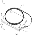
- Fig. 1 shows an optoelectronic device 3 according to the prior art to which optical fibers 2 are mechanically coupled. The device 3 is only shown for reasons of better understanding the interaction with the storage tray according to the invention.
- Fig. 1 shows the optoelectronic device 3 as a plate-like optoelectronic device having an upper side 8 which may be coupled with the bottom side 7 (see Fig. 2 , 4b , or 5 ) of a storage tray according to the invention.
- the optoelectronic device 3 may comprise fixing means 19, e.g. in the form of screw threads to which the storage tray may be connected using corresponding screws.
- the upper side 8 extends in a plane parallel to a plane spanned by the x- and y-axes.
- the device 3 also comprises a fiber exit port 11, preferably at the lateral surface 9 of the plate-like device 3, through which the optical fibers 2 are leaving the casing of device 3.
- the lateral surface 9 extends in a plane parallel to a plane spanned by the y- and z-axes.
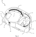
- Fig. 2 shows an assembly 20 according to the present invention comprising the optoelectronic device 3 shown in Fig. 1 having coupled thereon a storage tray 1 according to the present invention.
- the one or more optical fibers 2 leaving the fiber exit port 11 at the lateral surface 9 of the optoelectronic device 3 enter through a fiber receiving opening 10 of the fiber receiving portion 5 of the storage tray 1.
- the fiber receiving opening 10 preferably has a size that corresponds with the size of the fiber exit port 11. This has the advantage that the storage tray may not be shifted in the directions of the y-axis and the z-axis. From the fiber receiving portion 5, the optical fibers 2 run upwards (in direction of z-axis) into the fiber redirecting portion 6.
- the fiber redirecting portion 6 has at one side a wall with a round side surface 13 which allows the fibers to be redirected essentially in the direction opposite the direction in which they exit the fiber exit port 11, without being bent beyond their minimum bend radius.
- the optical fibers 2 may reach the fiber storage portion 4 which may allow the optical fibers 2, depending on their length, to be wrapped along the round lateral wall 14 once or several times.
- the fiber storage portion 4 may have one or more fiber retaining means 16 which are located at the upper side (opposite the bottom side 7) of the fiber storage portion 4, and are configured to retain the one or more optical fibers 2 in the fiber storage portion 4. As shown in Fig.
- the fiber retaining means 16 may extend from the upper side of the round lateral wall 14 in a plane parallel to the plane spanned by the x- and y-axes.
- Fig. 2 shows the fiber storage portion 4 adjacent to the upper side 8 of the optoelectronic device 3, which has the advantage that the resulting assembly 20 is very compact, the latter one being possible since the upper side 8 of the optoelectronic device 3 is coupled to the bottom side 7 of the storage tray 1.
- the round lateral wall 14 of the fiber storage portion 4 may have a lateral opening 23, preferably in the form of a slit which extends in the direction of the z-axis.
- This slit preferably extends over the entire width of the round lateral wall 14 and is open at that side of the round lateral wall 14 that is at the upper side of the storage tray 1.
- the lateral opening 23 in the form of a slit has the function of facilitating the movement of the optical fibers 2 towards the upper side of the storage tray 1 if removal of the optical fibers 2 is desired.
- Fiber movement towards the upper side of the storage tray 1 may be achieved by using a removal aid, e.g. in the form of a finger which may put in between the optical fibers 2 and the bottom side 7.
- the lateral opening 23 may continue into the bottom plate at the bottom side 7 of the storage tray 1.
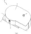
- Fig. 3 shows the assembly of Fig. 2 , wherein the upper side of the storage tray 1 is covered with a cover plate 17, e.g. by means of a fixing screw 22 which is configured to correspond to the screw thread 21.
- Fig. 4a shows the top view of an assembly 20 wherein the storage tray 1 is fixed to the optoelectronic device 3 via the fixing means 15, and has a cover plate 17 covering the upper side of the storage tray 1.
- Fig. 4a mainly serves the purpose of illustrating at which intersection A-A the assembly 20 is cut for the side view shown in Fig. 4b . That is, Fig. 4b shows the side view of an assembly according to the present invention cut at the intersection A-A shown in Fig. 4a .
- the assembly 20 shown in Fig. 4a is the same as shown in Figs. 2 and 3 .
- the optoelectronic device 3 shown in Fig. 3b is a ball grid array having ball grids at its bottom side (opposite the upper side 8) as electrical connecting means 18.
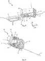
- Fig. 5 shows how a storage tray 1 may approach the optoelectronic device 3 before finally being coupled and before the optical fibers 2 are inserted into the storage tray 1.
- the optical fibers 2 For mounting the storage tray 1 on the optoelectronic device 3, the optical fibers 2 must be threaded into the storage tray 1 through the fiber receiving opening 10, and afterwards bent into the direction of the fiber storage portion 4. If the optical fibers 2 have a certain length, it is not at the same time possible to insert them into the fiber receiving opening 10 and to bend them into the directions of the fiber storage portion 4. Therefore, the storage tray 1 may comprise a further opening 12 at the side opposite the fiber receiving opening 10.
- This further opening 12 allows to pass the optical fibers 2 in linear direction through the fiber receiving portion 5 while the storage tray 1 approaches the optoelectronic device 3 in the direction of the x-axis.
- the further opening 12 is preferably configured as a slit being open at the upper side of the storage tray 1. This is necessary for the insertion of that part of the optical fiber 2 that exits the further opening 12 after the storage tray 1 is in the final position on the optoelectronic device 3.
- the storage tray 1 may comprise fixing means 15 in a position complementary to the fixing means 19 of the optoelectronic device 3 (as shown in Fig. 1 ). In doing so, the storage tray 1 may also be held in its position on the optoelectronic device 3 in the direction of the x-axis.
- Fig. 6 shows an assembly 20 wherein the storage tray 1 is brought in the final position with respect to the x-axis.
- the fixing means 15 are not yet fixed for the reason of illustrating their possible position.
- the optical fibers 2 are not yet inserted into the fiber storage portion 4, as they are in Fig. 2 .
Landscapes
- Physics & Mathematics (AREA)
- General Physics & Mathematics (AREA)
- Optics & Photonics (AREA)
- Engineering & Computer Science (AREA)
- Microelectronics & Electronic Packaging (AREA)
- Light Guides In General And Applications Therefor (AREA)
Abstract
Description
- The present invention relates to a storage tray for protecting one or more optical fibers mechanically coupled to an optoelectronic device according to
patent claim 1. The present invention further relates to an assembly according topatent claim 13 comprising a storage tray according to the present invention, and an optoelectronic device. - Optical fibers connected to an optoelectronic device are components which are only stable to a certain extent. Optical fibers should e.g. not be bent beyond their minimum radius to prevent damage. However, such optoelectronic components are often subjected to a handling process at the manufacturer, during shipment to the customer, and all movements at the customer until completion of the implementation of the optoelectronic device into the final product.
- Usually such optical fibers are therefore wrapped around a spool for transportation and handling purposes. Thereby, the wrapped fibers must be held in place under tension by a holding means, e.g. a clip, in order to prevent the fibers from unraveling. Such a spool wrapping of the optical fibers has different disadvantages, such as the following:
- Care must be taken that the fibers are not bent beyond their minimum radius.
- The optical fibers are exposed to the surrounding and may therefore be easily damaged by mechanical influences of the surrounding.
- The exposed fibers are not protected against heat, e.g. heat resulting from a solder reflow process which is often necessary to implement the optoelectronic device into a final product.
- That is, there is the need to provide a different solution which does not involve these disadvantages.
- For this, the inventors of the present invention provide a storage tray for protecting one or more optical fibers mechanically coupled to an optoelectronic device according to
patent claim 1. The storage tray according to the present invention is characterized in that it is configured to be capable of coupling with the optoelectronic device, and comprises a fiber storage portion which is configured to receive and store the one or more optical fibers. Further preferred embodiments are given in thedependent claims 2 to 12. - The storage tray according to the invention enables the storage of optical fibers of different lengths of an optoelectronic device to be safely stored or transported, since the optical fibers are protected by the lateral walls of the storage tray, i.e. are essentially not exposed to the surrounding. Furthermore, the storage tray according to the present invention is able to hold the wrapped optical fibers by the lateral walls in a specific radius, i.e. the fibers are not wrapped around a spool, and it is therefore not necessary to hold them by a clip under tension. In doing so, the storage tray according to the present invention provides an easy-to-handle and fiber-preserving method of encapsulating optical fibers. This offers fiber protection during manual and machine handling of the optoelectronic device and during transportation of the product to the end user as well as a clean top surface that lends itself to pick and place vacuum chuck holders. The storage tray according to the present invention provides protection over the entire fiber length of the optoelectronic device. The storage tray allows the operator to store the fibers straight away once the fibers have been attached to the storage tray. The tray remains in place all the way through shipping and handling, and until the end user has completed solder reflowing of the optoelectronic device.
- The optoelectronic device may be any optoelectronic device comprising electrical connecting means and one or more optical fibers, such as a ball grid array. The optoelectronic device is preferably a plate-like optoelectronic device. At the bottom surface (in the plane spanned by the x- and y-axes (
Fig. 1 )) of the optoelectronic device, the electrical connecting means are preferably located, wherein it is preferred that the upper surface (opposite the bottom surface) is free from electrical means. At one of the lateral surfaces (in the plane essentially vertical to the plane spanned by the x- and y-axes), a fiber exit port preferably extends from which the one or more fibers exit the interior of the optoelectronic device. - According to a further embodiment of the storage tray according to the invention, the storage tray further comprises a fiber receiving portion and a fiber redirecting portion. The fiber receiving portion is preferably present for receiving the optical fiber into the housing of the storage tray. The fiber directing portion has the function of redirecting the optical fiber into the fiber storage portion, in which the optical fiber may be present in a wrapped form.
- In a further embodiment, it is preferred that the storage tray according to the present invention has a bottom side which is configured to be coupled with the afore-mentioned upper side of a (plate-like) optoelectronic device. That is, in the coupled state of the storage tray and the optoelectronic device, the bottom side of the storage tray and the upper side of the optoelectronic device are parallel to each other. This arrangement has the advantage that space for storing the optical fiber may be saved compared to e.g. a case in which the optical fiber is stored in the extension direction of the (plate-like) optoelectronic device.
- According to a further embodiment of the storage tray of the present invention, it is preferred that the fiber receiving portion extends further downwards with respect to the bottom side, having a coupling surface facing a lateral surface of the plate-like optoelectronic device. In this case, the lateral surface is that lateral surface which comprises the fiber exit port. In doing so, the optical fiber may be protected from the exit throughout its entire extension. It is further preferred that the coupling surface of the storage tray comprises a fiber receiving opening. The fiber receiving opening is preferably configured such that it corresponds with the laterally extending fiber exit port at the lateral surface of the (plate-like) optoelectronic device, thereby being configured to fix the position of the storage tray with respect to the optoelectronic device.
- In a further embodiment, it is preferred that the fiber receiving portion of the storage tray according to the present invention has a further opening on the side opposite to the fiber receiving opening. This has the advantage that the storage tray may laterally approach the optoelectronic device from the side of the fiber exit port in that the optical fiber in a linear extension state may be guided through the fiber receiving portion where it enters at the fiber receiving opening and where it exits through the further opening. The further opening is preferably configured such that the part of the optical fiber which exits the fiber receiving portion may be guided back into the housing of the storage tray.
- It is preferred that the fiber receiving portion and the fiber redirecting portion are adjacent to each other. At least a part of the side walls of the fiber redirecting portion has preferably a round side surface. Such a round side surface is configured to redirect the one or more optical fibers into the fiber storage portion which is adjacent to the fiber redirecting portion and adjacent to the bottom side. The fiber storage portion may have an essentially round lateral wall configured to store the one or more optical fibers in a wound state.
- The storage tray according to the present invention may have one or more fixing means configured to fix the bottom side at the upper side of the plate-like optoelectronic device. The fixing means may be of any nature as long as it fulfills its function, namely, preferably fixing both components reversibly together. The fixing means may be a clip mechanism, but may also be screw or bolt (using the term "screw" herein is always referred to "screw or bolt") which corresponds to a screw thread present at the optoelectronic device.
- Moreover, the fiber storage portion may have one or more fiber retaining means being located at the upper side of the fiber storage portion, and being configured to retain the one or more optical fibers in the fiber storage portion. The fiber retaining means is preferably in the form of a protrusion located at the upper side of the storage tray, extending in a direction parallel to the plane of the bottom side. The fiber retaining means has the advantage that the optical fibers may be held in the wrapped state even if the upper side of the storage is not covered by a cover plate.
- In a further embodiment of the storage tray according to the present invention, it is preferred that the round lateral wall of the fiber storage portion has a lateral opening. The lateral opening may have the form of a slit which extends in the direction of the z-axis. This slit preferably extends over the entire width of the round lateral wall and is open at that side of the round lateral wall that is at the upper side of the storage tray. The lateral opening in the form of a slit has the function of facilitating the movement of the optical fibers towards the upper side of the storage tray if removal of the optical fibers is desired. Fiber movement towards the upper side of the storage tray may be achieved by using a removal aid, e.g. in the form of a finger which may be put in between the optical fibers and the bottom side of the storage tray. For reasons of protecting the optical fibers from being damaged by the removal aid, the lateral opening may continue into the bottom plate at the bottom side of the storage tray.
- However, the storage tray according to the present invention may also comprise a cover plate which is located on the upper side of the storage tray, the upper side being on the side opposite the bottom side of the storage tray. The cover plate may be of advantage if the storage tray is to be entirely closed, e.g. for reasons of heat protection of the encapsulated optical fibers.
- The storage tray according to the present invention may be made of metal or plastic, wherein plastic, i.e. a heat-resistant plastic, is more preferred from the standpoint of heat protection of the optical fibers. Heat protection of the optical fibers may then be an issue, if the optoelectronic device is e.g. a ball grid array which is installed by a solder reflow process. Alternatively (or additionally), the storage tray may be coated with a heat resistant material to further protect the optical fibers during high temperature solder reflow processes.
- The present invention further relates to an assembly which comprises the storage tray according to the present invention, and an optoelectronic device, wherein one or more optical fibers are coupled to the optoelectronic device, and wherein the one or more optical fibers are stored in the fiber storage portion of the storage tray. All features mentioned in connection of the storage tray according to the present invention are possible features of the assembly according to the present invention. In the assembly according to the present invention, it is preferred that the optoelectronic device comprises electrical connecting means at the bottom side of the optoelectronic device. It is further preferred that the optoelectronic device is a plate-like optoelectronic device having a fiber exit port in one of its lateral surfaces.
- The present invention is further explained with reference to the following
Figs. 1 to 6 which should, however, only be understood as exemplary and non-limiting for the scope of the present invention: - Fig. 1:
-
Fig. 1 shows an optoelectronic device according to the prior art to which optical fibers are mechanically coupled; - Fig. 2:
-
Fig. 2 shows an assembly according to the present invention comprising the optoelectronic device shown inFig. 1 having coupled thereon a storage tray according to the present invention; - Fig. 3:
-
Fig. 3 shows the same assembly ofFig. 2 having the upper side closed with a cover plate; - Fig. 4a:
-
Fig. 4a shows the top view of an assembly according to the present invention; - Fig. 4b:
-
Fig. 4b shows the side view of an assembly according to the present invention cut at the intersection A-A shown inFig. 4a ; - Fig. 5:
-
Fig. 5 shows how a storage tray according to the present invention may approach an optoelectronic device before finally being coupled and before the optical fiber is inserted into the storage tray; - Fig. 6:
-
Fig. 6 shows an assembly according to the present invention wherein the fixing means are not yet fixed and the optical fiber is not yet inserted into the storage tray. -
Fig. 1 shows anoptoelectronic device 3 according to the prior art to whichoptical fibers 2 are mechanically coupled. Thedevice 3 is only shown for reasons of better understanding the interaction with the storage tray according to the invention.Fig. 1 shows theoptoelectronic device 3 as a plate-like optoelectronic device having anupper side 8 which may be coupled with the bottom side 7 (seeFig. 2 ,4b , or5 ) of a storage tray according to the invention. For this reason, theoptoelectronic device 3 may comprise fixing means 19, e.g. in the form of screw threads to which the storage tray may be connected using corresponding screws. Theupper side 8 extends in a plane parallel to a plane spanned by the x- and y-axes. Thedevice 3 also comprises afiber exit port 11, preferably at thelateral surface 9 of the plate-like device 3, through which theoptical fibers 2 are leaving the casing ofdevice 3. Thelateral surface 9 extends in a plane parallel to a plane spanned by the y- and z-axes. -
Fig. 2 shows anassembly 20 according to the present invention comprising theoptoelectronic device 3 shown inFig. 1 having coupled thereon astorage tray 1 according to the present invention. The one or moreoptical fibers 2 leaving thefiber exit port 11 at thelateral surface 9 of theoptoelectronic device 3 enter through afiber receiving opening 10 of thefiber receiving portion 5 of thestorage tray 1. Thefiber receiving opening 10 preferably has a size that corresponds with the size of thefiber exit port 11. This has the advantage that the storage tray may not be shifted in the directions of the y-axis and the z-axis. From thefiber receiving portion 5, theoptical fibers 2 run upwards (in direction of z-axis) into thefiber redirecting portion 6. Thefiber redirecting portion 6 has at one side a wall with around side surface 13 which allows the fibers to be redirected essentially in the direction opposite the direction in which they exit thefiber exit port 11, without being bent beyond their minimum bend radius. From thefiber receiving portion 5, theoptical fibers 2 may reach thefiber storage portion 4 which may allow theoptical fibers 2, depending on their length, to be wrapped along the roundlateral wall 14 once or several times. Thefiber storage portion 4 may have one or more fiber retaining means 16 which are located at the upper side (opposite the bottom side 7) of thefiber storage portion 4, and are configured to retain the one or moreoptical fibers 2 in thefiber storage portion 4. As shown inFig. 2 , the fiber retaining means 16 may extend from the upper side of the roundlateral wall 14 in a plane parallel to the plane spanned by the x- and y-axes.Fig. 2 shows thefiber storage portion 4 adjacent to theupper side 8 of theoptoelectronic device 3, which has the advantage that the resultingassembly 20 is very compact, the latter one being possible since theupper side 8 of theoptoelectronic device 3 is coupled to thebottom side 7 of thestorage tray 1. Furthermore, the roundlateral wall 14 of thefiber storage portion 4 may have alateral opening 23, preferably in the form of a slit which extends in the direction of the z-axis. This slit preferably extends over the entire width of the roundlateral wall 14 and is open at that side of the roundlateral wall 14 that is at the upper side of thestorage tray 1. Thelateral opening 23 in the form of a slit has the function of facilitating the movement of theoptical fibers 2 towards the upper side of thestorage tray 1 if removal of theoptical fibers 2 is desired. Fiber movement towards the upper side of thestorage tray 1 may be achieved by using a removal aid, e.g. in the form of a finger which may put in between theoptical fibers 2 and thebottom side 7. For reasons of protecting the optical fibers of being damaged by the removal aid, thelateral opening 23 may continue into the bottom plate at thebottom side 7 of thestorage tray 1. -
Fig. 3 shows the assembly ofFig. 2 , wherein the upper side of thestorage tray 1 is covered with acover plate 17, e.g. by means of a fixingscrew 22 which is configured to correspond to thescrew thread 21. -
Fig. 4a shows the top view of anassembly 20 wherein thestorage tray 1 is fixed to theoptoelectronic device 3 via the fixing means 15, and has acover plate 17 covering the upper side of thestorage tray 1.Fig. 4a mainly serves the purpose of illustrating at which intersection A-A theassembly 20 is cut for the side view shown inFig. 4b . That is,Fig. 4b shows the side view of an assembly according to the present invention cut at the intersection A-A shown inFig. 4a . Apart from the different view, theassembly 20 shown inFig. 4a is the same as shown inFigs. 2 and3 . Theoptoelectronic device 3 shown inFig. 3b is a ball grid array having ball grids at its bottom side (opposite the upper side 8) as electrical connectingmeans 18. -
Fig. 5 shows how astorage tray 1 may approach theoptoelectronic device 3 before finally being coupled and before theoptical fibers 2 are inserted into thestorage tray 1. For mounting thestorage tray 1 on theoptoelectronic device 3, theoptical fibers 2 must be threaded into thestorage tray 1 through thefiber receiving opening 10, and afterwards bent into the direction of thefiber storage portion 4. If theoptical fibers 2 have a certain length, it is not at the same time possible to insert them into thefiber receiving opening 10 and to bend them into the directions of thefiber storage portion 4. Therefore, thestorage tray 1 may comprise afurther opening 12 at the side opposite thefiber receiving opening 10. This further opening 12 allows to pass theoptical fibers 2 in linear direction through thefiber receiving portion 5 while thestorage tray 1 approaches theoptoelectronic device 3 in the direction of the x-axis. Thefurther opening 12 is preferably configured as a slit being open at the upper side of thestorage tray 1. This is necessary for the insertion of that part of theoptical fiber 2 that exits thefurther opening 12 after thestorage tray 1 is in the final position on theoptoelectronic device 3. As shown inFig. 5 , thestorage tray 1 may comprise fixing means 15 in a position complementary to the fixing means 19 of the optoelectronic device 3 (as shown inFig. 1 ). In doing so, thestorage tray 1 may also be held in its position on theoptoelectronic device 3 in the direction of the x-axis. -
Fig. 6 shows anassembly 20 wherein thestorage tray 1 is brought in the final position with respect to the x-axis. The fixing means 15 are not yet fixed for the reason of illustrating their possible position. Furthermore, inFig. 6 theoptical fibers 2 are not yet inserted into thefiber storage portion 4, as they are inFig. 2 . -
- 1
- storage tray
- 2
- optical fibers
- 3
- optoelectronic device
- 4
- fiber storage portion
- 5
- fiber receiving portion
- 6
- fiber redirecting portion
- 7
- bottom side
- 8
- upper side
- 9
- lateral surface
- 10
- fiber receiving opening
- 11
- fiber exit port
- 12
- further opening
- 13
- round side surface
- 14
- round lateral wall
- 15
- fixing means (storage tray)
- 16
- fiber retaining means
- 17
- cover plate
- 18
- electrical connecting means
- 19
- fixing means (optoelectronic device)
- 20
- assembly
- 21
- screw thread for fixing the cover plate
- 22
- fixing screw
- 23
- lateral opening
Claims (15)
- A storage tray (1) for protecting one or more optical fibers (2) mechanically coupled to an optoelectronic device (3), characterized in that it is configured to be capable of coupling with the optoelectronic device (3) and comprises a fiber storage portion (4) which is configured to receive and store the one or more optical fibers (2).
- The storage tray (1) according to claim 1, further comprising a fiber receiving portion (5) and a fiber redirecting portion (6).
- The storage tray (1) according to claim 1 or 2, having a bottom side (7) which is configured to be coupled with an upper side (8) of a plate-like optoelectronic device (3).
- The storage tray (1) according to claim 3, wherein the fiber receiving portion (5) extends further downwards with respect to the bottom side (7), having a coupling surface (8) facing a lateral surface (9) of the plate-like optoelectronic device (3).
- The storage tray (1) according to claim 4, wherein the coupling surface (8) has a fiber receiving opening (10).
- The storage tray (1) according to claim 5, wherein the fiber receiving opening (10) is configured to correspond with a laterally extending fiber exit port (11) at the lateral surface (9) of the plate-like optoelectronic device (3), thereby being configured to fix the position of the storage tray (1) with respect to the optoelectronic device (3).
- The storage tray (1) according to any one of claims 4 to 6, wherein the fiber receiving portion (5) has a further opening (12) at the side opposite the fiber receiving opening (10).
- The storage tray (1) according to any one of claims 2 to 7, wherein the fiber receiving portion (5) and the fiber redirecting portion (6) are adjacent to each other, the fiber redirecting portion (6) having a round side surface (13) being configured to redirect the one or more fibers into the fiber storage portion (4) which is adjacent to the fiber redirecting portion (6) and adjacent to the bottom side (7).
- The storage tray (1) according to any one of claims 1 to 8, wherein the fiber storage portion (4) has an essentially round lateral wall (14) configured to store the one or more optical fibers (2) in a wound state.
- The storage tray (1) according to any one of claims 1 to 9 having one or more fixing means (15) configured to fix the bottom side (7) at the upper side (8) of the plate-like optoelectronic device (3).
- The storage tray (1) according to any one of claims 1 to 10, wherein the fiber storage portion (4) has one or more fiber retaining means (16) being located at the upper side of the fiber storage portion (4), and being configured to retain the one or more optical fibers in the fiber storage portion (4).
- The storage tray (1) according to any one of claims 1 to 11, having a cover plate (17) which is located on the upper side of the storage tray (1), the upper side being opposite to the bottom side (7) of the storage tray (1).
- An assembly (20) comprising a storage tray (1) according to any one of claims 1 to 12, and an optoelectronic device (3), wherein one or more optical fibers (2) are coupled to the optoelectronic device (3), and wherein the one or more optical fibers (2) are stored in the fiber storage portion (4) of the storage tray (1).
- The assembly (20) according to claim 13, wherein the optoelectronic device (3) comprises electrical connecting means (18) at the bottom side of the optoelectronic device (3).
- The assembly (20) according to any one of claims 1 to 14, wherein the optoelectronic device (3) is a plate-like optoelectronic device having a fiber exit port (11) at one of the lateral surfaces.
Priority Applications (2)
| Application Number | Priority Date | Filing Date | Title |
|---|---|---|---|
| EP19198765.0A EP3796059B1 (en) | 2019-09-20 | 2019-09-20 | Storage tray for protecting optical fibers mechanically coupled to an optoelectronic device |
| US17/019,608 US11204476B2 (en) | 2019-09-20 | 2020-09-14 | Storage tray for protecting optical fibers mechanically coupled to an optoelectronic device |
Applications Claiming Priority (1)
| Application Number | Priority Date | Filing Date | Title |
|---|---|---|---|
| EP19198765.0A EP3796059B1 (en) | 2019-09-20 | 2019-09-20 | Storage tray for protecting optical fibers mechanically coupled to an optoelectronic device |
Publications (2)
| Publication Number | Publication Date |
|---|---|
| EP3796059A1 true EP3796059A1 (en) | 2021-03-24 |
| EP3796059B1 EP3796059B1 (en) | 2023-09-06 |
Family
ID=67998404
Family Applications (1)
| Application Number | Title | Priority Date | Filing Date |
|---|---|---|---|
| EP19198765.0A Active EP3796059B1 (en) | 2019-09-20 | 2019-09-20 | Storage tray for protecting optical fibers mechanically coupled to an optoelectronic device |
Country Status (2)
| Country | Link |
|---|---|
| US (1) | US11204476B2 (en) |
| EP (1) | EP3796059B1 (en) |
Families Citing this family (1)
| Publication number | Priority date | Publication date | Assignee | Title |
|---|---|---|---|---|
| US11809001B2 (en) * | 2022-04-07 | 2023-11-07 | Mellanox Technologies Ltd. | Network interface device with external optical connector |
Citations (4)
| Publication number | Priority date | Publication date | Assignee | Title |
|---|---|---|---|---|
| US6249634B1 (en) * | 1999-01-26 | 2001-06-19 | General Instrument Corporation | Fiber optic cable coiling tray |
| WO2002071123A1 (en) * | 2001-02-16 | 2002-09-12 | Telefonaktiebolaget Lm Ericsson (Publ) | A device for enclosing an electrooptic converter and at least one optical fibre connection |
| US20040047581A1 (en) * | 2002-09-11 | 2004-03-11 | Allied Telesis Kabushiki Kaisha | Media converter |
| JP2006115341A (en) * | 2004-10-15 | 2006-04-27 | Dx Antenna Co Ltd | Structure of optical receiver for storing optical fiber excessive length |
Family Cites Families (14)
| Publication number | Priority date | Publication date | Assignee | Title |
|---|---|---|---|---|
| JP2000013460A (en) * | 1998-06-23 | 2000-01-14 | Fujitsu Ltd | Line termination equipment |
| FR2811786B1 (en) | 2000-07-17 | 2006-07-07 | Serge Benchimol | METHOD FOR SECURING A TRANSACTION VIA A TELECOMMUNICATION NETWORK, AND SYSTEM FOR IMPLEMENTING THE METHOD |
| US6741785B2 (en) * | 2002-04-19 | 2004-05-25 | Plexus Corporation | Optical fiber management system and method |
| US6974260B2 (en) * | 2003-07-30 | 2005-12-13 | Emcore Corporation | Flexible substrate for routing fibers in an optical transceiver |
| GB0423743D0 (en) * | 2004-10-26 | 2004-11-24 | Tyco Electronics Raychem Nv | A signal distribution assembly and a connector holder for use therewith |
| US7785020B2 (en) * | 2007-07-06 | 2010-08-31 | Finisar Corporation | Optical component and transceiver packaging |
| US8346043B2 (en) * | 2009-07-30 | 2013-01-01 | Jds Uniphase Corporation | Fiber tray |
| US9519117B2 (en) * | 2012-04-06 | 2016-12-13 | Infinera Corporation | Optical fiber track system and method for using thereof |
| JP6295811B2 (en) * | 2014-05-08 | 2018-03-20 | 住友電気工業株式会社 | Optical transceiver |
| JP6398318B2 (en) * | 2014-05-21 | 2018-10-03 | 住友電気工業株式会社 | Optical transceiver |
| US9871590B2 (en) * | 2014-10-10 | 2018-01-16 | Sumitomo Electric Industries, Ltd. | Optical transceiver implementing erbium doped fiber amplifier |
| CN108445591A (en) * | 2017-02-16 | 2018-08-24 | 住友电气工业株式会社 | Optical transceiver |
| JP7056092B2 (en) * | 2017-11-17 | 2022-04-19 | 富士通オプティカルコンポーネンツ株式会社 | Optical communication device |
| US11163128B2 (en) * | 2019-03-20 | 2021-11-02 | Ppc Broadband, Inc. | Enclosure for spliced cables for use in an outdoor environment |
-
2019
- 2019-09-20 EP EP19198765.0A patent/EP3796059B1/en active Active
-
2020
- 2020-09-14 US US17/019,608 patent/US11204476B2/en active Active
Patent Citations (4)
| Publication number | Priority date | Publication date | Assignee | Title |
|---|---|---|---|---|
| US6249634B1 (en) * | 1999-01-26 | 2001-06-19 | General Instrument Corporation | Fiber optic cable coiling tray |
| WO2002071123A1 (en) * | 2001-02-16 | 2002-09-12 | Telefonaktiebolaget Lm Ericsson (Publ) | A device for enclosing an electrooptic converter and at least one optical fibre connection |
| US20040047581A1 (en) * | 2002-09-11 | 2004-03-11 | Allied Telesis Kabushiki Kaisha | Media converter |
| JP2006115341A (en) * | 2004-10-15 | 2006-04-27 | Dx Antenna Co Ltd | Structure of optical receiver for storing optical fiber excessive length |
Also Published As
| Publication number | Publication date |
|---|---|
| US11204476B2 (en) | 2021-12-21 |
| US20210088741A1 (en) | 2021-03-25 |
| EP3796059B1 (en) | 2023-09-06 |
Similar Documents
| Publication | Publication Date | Title |
|---|---|---|
| US5796908A (en) | Optical fiber organizing tray | |
| US8346043B2 (en) | Fiber tray | |
| JPH06324219A (en) | Cabinet for optical fiber | |
| US11204476B2 (en) | Storage tray for protecting optical fibers mechanically coupled to an optoelectronic device | |
| JP6943649B2 (en) | Manufacturing method of branch protector | |
| JP7102931B2 (en) | Optical connector cable and metal parts | |
| KR100398832B1 (en) | Spool case for bonding wire and method for handling spool using the case | |
| US11852882B2 (en) | Packaging assembly for telecommunications equipment | |
| KR20010113650A (en) | Passive platform for holding optical components | |
| JP7063107B2 (en) | Optical connector cable and metal parts | |
| EP0800246B1 (en) | Apparatus for housing high-heat-emission electrooptical components and method of assembling said apparatus | |
| JP6904820B2 (en) | Branch protector and wire harness | |
| JP4272598B2 (en) | Optical fiber tray and optical fiber extra length processing method using the tray | |
| JP2005164630A (en) | Optical fiber extra length processing tool | |
| US6714714B1 (en) | Butterfly package pallet | |
| JP2008281711A (en) | Light closure | |
| JP4211987B2 (en) | Optical outlet for mounting on distribution board | |
| JP7237425B2 (en) | Tube storage jig | |
| JP5234991B2 (en) | Adapter storage module | |
| JP2014085468A (en) | Optical connection box | |
| JPS6215846B2 (en) | ||
| JP7547129B2 (en) | Fiber Optic Tray | |
| JP7349103B2 (en) | optical receiver | |
| JP6713205B2 (en) | Wiring storage structure | |
| JP4069032B2 (en) | Optical fiber cable connection auxiliary device and optical fiber cable connection method using the auxiliary device |
Legal Events
| Date | Code | Title | Description |
|---|---|---|---|
| PUAI | Public reference made under article 153(3) epc to a published international application that has entered the european phase |
Free format text: ORIGINAL CODE: 0009012 |
|
| STAA | Information on the status of an ep patent application or granted ep patent |
Free format text: STATUS: THE APPLICATION HAS BEEN PUBLISHED |
|
| AK | Designated contracting states |
Kind code of ref document: A1 Designated state(s): AL AT BE BG CH CY CZ DE DK EE ES FI FR GB GR HR HU IE IS IT LI LT LU LV MC MK MT NL NO PL PT RO RS SE SI SK SM TR |
|
| AX | Request for extension of the european patent |
Extension state: BA ME |
|
| STAA | Information on the status of an ep patent application or granted ep patent |
Free format text: STATUS: REQUEST FOR EXAMINATION WAS MADE |
|
| 17P | Request for examination filed |
Effective date: 20210618 |
|
| RBV | Designated contracting states (corrected) |
Designated state(s): AL AT BE BG CH CY CZ DE DK EE ES FI FR GB GR HR HU IE IS IT LI LT LU LV MC MK MT NL NO PL PT RO RS SE SI SK SM TR |
|
| GRAP | Despatch of communication of intention to grant a patent |
Free format text: ORIGINAL CODE: EPIDOSNIGR1 |
|
| STAA | Information on the status of an ep patent application or granted ep patent |
Free format text: STATUS: GRANT OF PATENT IS INTENDED |
|
| RIC1 | Information provided on ipc code assigned before grant |
Ipc: G02B 6/42 20060101ALN20230306BHEP Ipc: G02B 6/44 20060101AFI20230306BHEP |
|
| INTG | Intention to grant announced |
Effective date: 20230404 |
|
| P01 | Opt-out of the competence of the unified patent court (upc) registered |
Effective date: 20230519 |
|
| GRAS | Grant fee paid |
Free format text: ORIGINAL CODE: EPIDOSNIGR3 |
|
| GRAA | (expected) grant |
Free format text: ORIGINAL CODE: 0009210 |
|
| STAA | Information on the status of an ep patent application or granted ep patent |
Free format text: STATUS: THE PATENT HAS BEEN GRANTED |
|
| AK | Designated contracting states |
Kind code of ref document: B1 Designated state(s): AL AT BE BG CH CY CZ DE DK EE ES FI FR GB GR HR HU IE IS IT LI LT LU LV MC MK MT NL NO PL PT RO RS SE SI SK SM TR |
|
| RAP3 | Party data changed (applicant data changed or rights of an application transferred) |
Owner name: ADTRAN NETWORKS SE |
|
| REG | Reference to a national code |
Ref country code: GB Ref legal event code: FG4D |
|
| REG | Reference to a national code |
Ref country code: CH Ref legal event code: EP |
|
| REG | Reference to a national code |
Ref country code: IE Ref legal event code: FG4D |
|
| REG | Reference to a national code |
Ref country code: DE Ref legal event code: R096 Ref document number: 602019036632 Country of ref document: DE |
|
| REG | Reference to a national code |
Ref country code: LT Ref legal event code: MG9D |
|
| REG | Reference to a national code |
Ref country code: NL Ref legal event code: MP Effective date: 20230906 |
|
| PG25 | Lapsed in a contracting state [announced via postgrant information from national office to epo] |
Ref country code: GR Free format text: LAPSE BECAUSE OF FAILURE TO SUBMIT A TRANSLATION OF THE DESCRIPTION OR TO PAY THE FEE WITHIN THE PRESCRIBED TIME-LIMIT Effective date: 20231207 |
|
| PG25 | Lapsed in a contracting state [announced via postgrant information from national office to epo] |
Ref country code: SE Free format text: LAPSE BECAUSE OF FAILURE TO SUBMIT A TRANSLATION OF THE DESCRIPTION OR TO PAY THE FEE WITHIN THE PRESCRIBED TIME-LIMIT Effective date: 20230906 Ref country code: RS Free format text: LAPSE BECAUSE OF FAILURE TO SUBMIT A TRANSLATION OF THE DESCRIPTION OR TO PAY THE FEE WITHIN THE PRESCRIBED TIME-LIMIT Effective date: 20230906 Ref country code: NO Free format text: LAPSE BECAUSE OF FAILURE TO SUBMIT A TRANSLATION OF THE DESCRIPTION OR TO PAY THE FEE WITHIN THE PRESCRIBED TIME-LIMIT Effective date: 20231206 Ref country code: LV Free format text: LAPSE BECAUSE OF FAILURE TO SUBMIT A TRANSLATION OF THE DESCRIPTION OR TO PAY THE FEE WITHIN THE PRESCRIBED TIME-LIMIT Effective date: 20230906 Ref country code: LT Free format text: LAPSE BECAUSE OF FAILURE TO SUBMIT A TRANSLATION OF THE DESCRIPTION OR TO PAY THE FEE WITHIN THE PRESCRIBED TIME-LIMIT Effective date: 20230906 Ref country code: HR Free format text: LAPSE BECAUSE OF FAILURE TO SUBMIT A TRANSLATION OF THE DESCRIPTION OR TO PAY THE FEE WITHIN THE PRESCRIBED TIME-LIMIT Effective date: 20230906 Ref country code: GR Free format text: LAPSE BECAUSE OF FAILURE TO SUBMIT A TRANSLATION OF THE DESCRIPTION OR TO PAY THE FEE WITHIN THE PRESCRIBED TIME-LIMIT Effective date: 20231207 Ref country code: FI Free format text: LAPSE BECAUSE OF FAILURE TO SUBMIT A TRANSLATION OF THE DESCRIPTION OR TO PAY THE FEE WITHIN THE PRESCRIBED TIME-LIMIT Effective date: 20230906 |
|
| REG | Reference to a national code |
Ref country code: AT Ref legal event code: MK05 Ref document number: 1609271 Country of ref document: AT Kind code of ref document: T Effective date: 20230906 |
|
| PG25 | Lapsed in a contracting state [announced via postgrant information from national office to epo] |
Ref country code: NL Free format text: LAPSE BECAUSE OF FAILURE TO SUBMIT A TRANSLATION OF THE DESCRIPTION OR TO PAY THE FEE WITHIN THE PRESCRIBED TIME-LIMIT Effective date: 20230906 |
|
| PG25 | Lapsed in a contracting state [announced via postgrant information from national office to epo] |
Ref country code: IS Free format text: LAPSE BECAUSE OF FAILURE TO SUBMIT A TRANSLATION OF THE DESCRIPTION OR TO PAY THE FEE WITHIN THE PRESCRIBED TIME-LIMIT Effective date: 20240106 |
|
| PG25 | Lapsed in a contracting state [announced via postgrant information from national office to epo] |
Ref country code: AT Free format text: LAPSE BECAUSE OF FAILURE TO SUBMIT A TRANSLATION OF THE DESCRIPTION OR TO PAY THE FEE WITHIN THE PRESCRIBED TIME-LIMIT Effective date: 20230906 |
|
| PG25 | Lapsed in a contracting state [announced via postgrant information from national office to epo] |
Ref country code: ES Free format text: LAPSE BECAUSE OF FAILURE TO SUBMIT A TRANSLATION OF THE DESCRIPTION OR TO PAY THE FEE WITHIN THE PRESCRIBED TIME-LIMIT Effective date: 20230906 |
|
| PG25 | Lapsed in a contracting state [announced via postgrant information from national office to epo] |
Ref country code: SM Free format text: LAPSE BECAUSE OF FAILURE TO SUBMIT A TRANSLATION OF THE DESCRIPTION OR TO PAY THE FEE WITHIN THE PRESCRIBED TIME-LIMIT Effective date: 20230906 Ref country code: RO Free format text: LAPSE BECAUSE OF FAILURE TO SUBMIT A TRANSLATION OF THE DESCRIPTION OR TO PAY THE FEE WITHIN THE PRESCRIBED TIME-LIMIT Effective date: 20230906 Ref country code: IS Free format text: LAPSE BECAUSE OF FAILURE TO SUBMIT A TRANSLATION OF THE DESCRIPTION OR TO PAY THE FEE WITHIN THE PRESCRIBED TIME-LIMIT Effective date: 20240106 Ref country code: ES Free format text: LAPSE BECAUSE OF FAILURE TO SUBMIT A TRANSLATION OF THE DESCRIPTION OR TO PAY THE FEE WITHIN THE PRESCRIBED TIME-LIMIT Effective date: 20230906 Ref country code: EE Free format text: LAPSE BECAUSE OF FAILURE TO SUBMIT A TRANSLATION OF THE DESCRIPTION OR TO PAY THE FEE WITHIN THE PRESCRIBED TIME-LIMIT Effective date: 20230906 Ref country code: CZ Free format text: LAPSE BECAUSE OF FAILURE TO SUBMIT A TRANSLATION OF THE DESCRIPTION OR TO PAY THE FEE WITHIN THE PRESCRIBED TIME-LIMIT Effective date: 20230906 Ref country code: AT Free format text: LAPSE BECAUSE OF FAILURE TO SUBMIT A TRANSLATION OF THE DESCRIPTION OR TO PAY THE FEE WITHIN THE PRESCRIBED TIME-LIMIT Effective date: 20230906 Ref country code: PT Free format text: LAPSE BECAUSE OF FAILURE TO SUBMIT A TRANSLATION OF THE DESCRIPTION OR TO PAY THE FEE WITHIN THE PRESCRIBED TIME-LIMIT Effective date: 20240108 Ref country code: SK Free format text: LAPSE BECAUSE OF FAILURE TO SUBMIT A TRANSLATION OF THE DESCRIPTION OR TO PAY THE FEE WITHIN THE PRESCRIBED TIME-LIMIT Effective date: 20230906 |
|
| REG | Reference to a national code |
Ref country code: CH Ref legal event code: PL |
|
| PG25 | Lapsed in a contracting state [announced via postgrant information from national office to epo] |
Ref country code: LU Free format text: LAPSE BECAUSE OF NON-PAYMENT OF DUE FEES Effective date: 20230920 |
|
| REG | Reference to a national code |
Ref country code: BE Ref legal event code: MM Effective date: 20230930 |
|
| PG25 | Lapsed in a contracting state [announced via postgrant information from national office to epo] |
Ref country code: PL Free format text: LAPSE BECAUSE OF FAILURE TO SUBMIT A TRANSLATION OF THE DESCRIPTION OR TO PAY THE FEE WITHIN THE PRESCRIBED TIME-LIMIT Effective date: 20230906 Ref country code: LU Free format text: LAPSE BECAUSE OF NON-PAYMENT OF DUE FEES Effective date: 20230920 Ref country code: IT Free format text: LAPSE BECAUSE OF FAILURE TO SUBMIT A TRANSLATION OF THE DESCRIPTION OR TO PAY THE FEE WITHIN THE PRESCRIBED TIME-LIMIT Effective date: 20230906 |
|
| REG | Reference to a national code |
Ref country code: DE Ref legal event code: R097 Ref document number: 602019036632 Country of ref document: DE |
|
| PG25 | Lapsed in a contracting state [announced via postgrant information from national office to epo] |
Ref country code: MC Free format text: LAPSE BECAUSE OF FAILURE TO SUBMIT A TRANSLATION OF THE DESCRIPTION OR TO PAY THE FEE WITHIN THE PRESCRIBED TIME-LIMIT Effective date: 20230906 |
|
| REG | Reference to a national code |
Ref country code: IE Ref legal event code: MM4A |
|
| PG25 | Lapsed in a contracting state [announced via postgrant information from national office to epo] |
Ref country code: IE Free format text: LAPSE BECAUSE OF NON-PAYMENT OF DUE FEES Effective date: 20230920 |
|
| PG25 | Lapsed in a contracting state [announced via postgrant information from national office to epo] |
Ref country code: DK Free format text: LAPSE BECAUSE OF FAILURE TO SUBMIT A TRANSLATION OF THE DESCRIPTION OR TO PAY THE FEE WITHIN THE PRESCRIBED TIME-LIMIT Effective date: 20230906 |
|
| PLBE | No opposition filed within time limit |
Free format text: ORIGINAL CODE: 0009261 |
|
| STAA | Information on the status of an ep patent application or granted ep patent |
Free format text: STATUS: NO OPPOSITION FILED WITHIN TIME LIMIT |
|
| PG25 | Lapsed in a contracting state [announced via postgrant information from national office to epo] |
Ref country code: CH Free format text: LAPSE BECAUSE OF NON-PAYMENT OF DUE FEES Effective date: 20230930 |
|
| PG25 | Lapsed in a contracting state [announced via postgrant information from national office to epo] |
Ref country code: MC Free format text: LAPSE BECAUSE OF FAILURE TO SUBMIT A TRANSLATION OF THE DESCRIPTION OR TO PAY THE FEE WITHIN THE PRESCRIBED TIME-LIMIT Effective date: 20230906 Ref country code: IE Free format text: LAPSE BECAUSE OF NON-PAYMENT OF DUE FEES Effective date: 20230920 Ref country code: DK Free format text: LAPSE BECAUSE OF FAILURE TO SUBMIT A TRANSLATION OF THE DESCRIPTION OR TO PAY THE FEE WITHIN THE PRESCRIBED TIME-LIMIT Effective date: 20230906 Ref country code: CH Free format text: LAPSE BECAUSE OF NON-PAYMENT OF DUE FEES Effective date: 20230930 Ref country code: SI Free format text: LAPSE BECAUSE OF FAILURE TO SUBMIT A TRANSLATION OF THE DESCRIPTION OR TO PAY THE FEE WITHIN THE PRESCRIBED TIME-LIMIT Effective date: 20230906 |
|
| 26N | No opposition filed |
Effective date: 20240607 |
|
| PG25 | Lapsed in a contracting state [announced via postgrant information from national office to epo] |
Ref country code: BE Free format text: LAPSE BECAUSE OF NON-PAYMENT OF DUE FEES Effective date: 20230930 |
|
| PG25 | Lapsed in a contracting state [announced via postgrant information from national office to epo] |
Ref country code: FR Free format text: LAPSE BECAUSE OF NON-PAYMENT OF DUE FEES Effective date: 20231106 |
|
| PG25 | Lapsed in a contracting state [announced via postgrant information from national office to epo] |
Ref country code: FR Free format text: LAPSE BECAUSE OF NON-PAYMENT OF DUE FEES Effective date: 20231106 |
|
| PG25 | Lapsed in a contracting state [announced via postgrant information from national office to epo] |
Ref country code: BG Free format text: LAPSE BECAUSE OF FAILURE TO SUBMIT A TRANSLATION OF THE DESCRIPTION OR TO PAY THE FEE WITHIN THE PRESCRIBED TIME-LIMIT Effective date: 20230906 |
|
| PG25 | Lapsed in a contracting state [announced via postgrant information from national office to epo] |
Ref country code: BG Free format text: LAPSE BECAUSE OF FAILURE TO SUBMIT A TRANSLATION OF THE DESCRIPTION OR TO PAY THE FEE WITHIN THE PRESCRIBED TIME-LIMIT Effective date: 20230906 |
|
| PG25 | Lapsed in a contracting state [announced via postgrant information from national office to epo] |
Ref country code: CY Free format text: LAPSE BECAUSE OF FAILURE TO SUBMIT A TRANSLATION OF THE DESCRIPTION OR TO PAY THE FEE WITHIN THE PRESCRIBED TIME-LIMIT; INVALID AB INITIO Effective date: 20190920 |
|
| PG25 | Lapsed in a contracting state [announced via postgrant information from national office to epo] |
Ref country code: HU Free format text: LAPSE BECAUSE OF FAILURE TO SUBMIT A TRANSLATION OF THE DESCRIPTION OR TO PAY THE FEE WITHIN THE PRESCRIBED TIME-LIMIT; INVALID AB INITIO Effective date: 20190920 |
|
| PGFP | Annual fee paid to national office [announced via postgrant information from national office to epo] |
Ref country code: DE Payment date: 20250919 Year of fee payment: 7 |
|
| PGFP | Annual fee paid to national office [announced via postgrant information from national office to epo] |
Ref country code: GB Payment date: 20250923 Year of fee payment: 7 |
|
| PG25 | Lapsed in a contracting state [announced via postgrant information from national office to epo] |
Ref country code: TR Free format text: LAPSE BECAUSE OF FAILURE TO SUBMIT A TRANSLATION OF THE DESCRIPTION OR TO PAY THE FEE WITHIN THE PRESCRIBED TIME-LIMIT Effective date: 20230906 |