EP3796044A1 - A flexible radar support for absorbing vibration deviation - Google Patents
A flexible radar support for absorbing vibration deviation Download PDFInfo
- Publication number
- EP3796044A1 EP3796044A1 EP19219689.7A EP19219689A EP3796044A1 EP 3796044 A1 EP3796044 A1 EP 3796044A1 EP 19219689 A EP19219689 A EP 19219689A EP 3796044 A1 EP3796044 A1 EP 3796044A1
- Authority
- EP
- European Patent Office
- Prior art keywords
- support
- base
- flexible
- radar
- top cover
- Prior art date
- Legal status (The legal status is an assumption and is not a legal conclusion. Google has not performed a legal analysis and makes no representation as to the accuracy of the status listed.)
- Granted
Links
Images


Classifications
-
- G—PHYSICS
- G01—MEASURING; TESTING
- G01S—RADIO DIRECTION-FINDING; RADIO NAVIGATION; DETERMINING DISTANCE OR VELOCITY BY USE OF RADIO WAVES; LOCATING OR PRESENCE-DETECTING BY USE OF THE REFLECTION OR RERADIATION OF RADIO WAVES; ANALOGOUS ARRANGEMENTS USING OTHER WAVES
- G01S7/00—Details of systems according to groups G01S13/00, G01S15/00, G01S17/00
- G01S7/02—Details of systems according to groups G01S13/00, G01S15/00, G01S17/00 of systems according to group G01S13/00
- G01S7/03—Details of HF subsystems specially adapted therefor, e.g. common to transmitter and receiver
- G01S7/032—Constructional details for solid-state radar subsystems
-
- G—PHYSICS
- G01—MEASURING; TESTING
- G01S—RADIO DIRECTION-FINDING; RADIO NAVIGATION; DETERMINING DISTANCE OR VELOCITY BY USE OF RADIO WAVES; LOCATING OR PRESENCE-DETECTING BY USE OF THE REFLECTION OR RERADIATION OF RADIO WAVES; ANALOGOUS ARRANGEMENTS USING OTHER WAVES
- G01S13/00—Systems using the reflection or reradiation of radio waves, e.g. radar systems; Analogous systems using reflection or reradiation of waves whose nature or wavelength is irrelevant or unspecified
- G01S13/88—Radar or analogous systems specially adapted for specific applications
- G01S13/93—Radar or analogous systems specially adapted for specific applications for anti-collision purposes
-
- G—PHYSICS
- G01—MEASURING; TESTING
- G01S—RADIO DIRECTION-FINDING; RADIO NAVIGATION; DETERMINING DISTANCE OR VELOCITY BY USE OF RADIO WAVES; LOCATING OR PRESENCE-DETECTING BY USE OF THE REFLECTION OR RERADIATION OF RADIO WAVES; ANALOGOUS ARRANGEMENTS USING OTHER WAVES
- G01S7/00—Details of systems according to groups G01S13/00, G01S15/00, G01S17/00
- G01S7/02—Details of systems according to groups G01S13/00, G01S15/00, G01S17/00 of systems according to group G01S13/00
- G01S7/35—Details of non-pulse systems
-
- G—PHYSICS
- G01—MEASURING; TESTING
- G01S—RADIO DIRECTION-FINDING; RADIO NAVIGATION; DETERMINING DISTANCE OR VELOCITY BY USE OF RADIO WAVES; LOCATING OR PRESENCE-DETECTING BY USE OF THE REFLECTION OR RERADIATION OF RADIO WAVES; ANALOGOUS ARRANGEMENTS USING OTHER WAVES
- G01S13/00—Systems using the reflection or reradiation of radio waves, e.g. radar systems; Analogous systems using reflection or reradiation of waves whose nature or wavelength is irrelevant or unspecified
- G01S13/88—Radar or analogous systems specially adapted for specific applications
- G01S13/93—Radar or analogous systems specially adapted for specific applications for anti-collision purposes
- G01S13/931—Radar or analogous systems specially adapted for specific applications for anti-collision purposes of land vehicles
-
- G—PHYSICS
- G01—MEASURING; TESTING
- G01S—RADIO DIRECTION-FINDING; RADIO NAVIGATION; DETERMINING DISTANCE OR VELOCITY BY USE OF RADIO WAVES; LOCATING OR PRESENCE-DETECTING BY USE OF THE REFLECTION OR RERADIATION OF RADIO WAVES; ANALOGOUS ARRANGEMENTS USING OTHER WAVES
- G01S13/00—Systems using the reflection or reradiation of radio waves, e.g. radar systems; Analogous systems using reflection or reradiation of waves whose nature or wavelength is irrelevant or unspecified
- G01S13/88—Radar or analogous systems specially adapted for specific applications
- G01S13/93—Radar or analogous systems specially adapted for specific applications for anti-collision purposes
- G01S13/931—Radar or analogous systems specially adapted for specific applications for anti-collision purposes of land vehicles
- G01S2013/9327—Sensor installation details
-
- G—PHYSICS
- G01—MEASURING; TESTING
- G01S—RADIO DIRECTION-FINDING; RADIO NAVIGATION; DETERMINING DISTANCE OR VELOCITY BY USE OF RADIO WAVES; LOCATING OR PRESENCE-DETECTING BY USE OF THE REFLECTION OR RERADIATION OF RADIO WAVES; ANALOGOUS ARRANGEMENTS USING OTHER WAVES
- G01S13/00—Systems using the reflection or reradiation of radio waves, e.g. radar systems; Analogous systems using reflection or reradiation of waves whose nature or wavelength is irrelevant or unspecified
- G01S13/88—Radar or analogous systems specially adapted for specific applications
- G01S13/93—Radar or analogous systems specially adapted for specific applications for anti-collision purposes
- G01S13/931—Radar or analogous systems specially adapted for specific applications for anti-collision purposes of land vehicles
- G01S2013/9327—Sensor installation details
- G01S2013/93275—Sensor installation details in the bumper area
-
- G—PHYSICS
- G01—MEASURING; TESTING
- G01S—RADIO DIRECTION-FINDING; RADIO NAVIGATION; DETERMINING DISTANCE OR VELOCITY BY USE OF RADIO WAVES; LOCATING OR PRESENCE-DETECTING BY USE OF THE REFLECTION OR RERADIATION OF RADIO WAVES; ANALOGOUS ARRANGEMENTS USING OTHER WAVES
- G01S7/00—Details of systems according to groups G01S13/00, G01S15/00, G01S17/00
- G01S7/02—Details of systems according to groups G01S13/00, G01S15/00, G01S17/00 of systems according to group G01S13/00
- G01S7/027—Constructional details of housings, e.g. form, type, material or ruggedness
Definitions
- the invention relates to the field of radar support, and more particularly, to a flexible radar support that absorbs vibration deviation.
- high-precision radars are mostly integrated in automobile body frame or grille regions. Those regions usually can provide a relatively stable positioning system for a radar. During the course of driving, the impact on the radar is relatively small, but this has certain limitation on the arrangement of the radar.
- An objective of the invention is to provide a flexible radar support that absorbs vibration deviation, thus solving the problem in the prior art that the detection precision of a radar is affected by an automobile's vibrations.
- a flexible radar support for absorbing vibration deviation comprises a support base and a support top cover that are engaged with each other in an interlocking manner.
- a housing space for arranging a radar is formed between the support base and the support top cover.
- the support base comprises: a centrally arranged base center, and a base edge circumferentially arranged around the base center. The base edge and the base center are connected through four flexible structures that form U-shaped cantilever beams protruding towards the support top cover.
- the four U-shaped cantilever beams are symmetrically arranged in four directions of up, down, left, and right directions, respectively.
- corner regions between the base edge and the base center are hollowed out and disconnected.
- first protruding tabs extending towards the base edge and keeping spaced from the base edge, are arranged in the four corner regions of the base center.
- the first protruding tabs are provided with screw holes.
- second protruding tabs for cooperating with the first protruding tabs are arranged in four corner regions of the support top cover.
- the second protruding tabs are provided with screw holes.
- the support base and the support top cover are fastened to each other by self-tapping screws.
- the wall thickness of a side wall of the U-shaped cantilever beams is 2.0 mm to 3.0 mm.
- the wall thickness of the bent portion of the U-shaped cantilever beams is 1.0 mm to 2.0 mm.
- the radius of a round angle of a bent portion of the U-shaped cantilever beams is 3.5 mm to 4.5 mm.
- the angle formed by two side walls of the U-shaped cantilever beams is 40° to 50°.
- the flexible radar support provided by the invention, thanks to the design of U-shaped flexible structures, even in the situation where an automobile body vibrates at a large amplitude, the flexible radar support can still absorb swaying(shaking) in the up and down, and left and right directions during the course of driving, thereby reducing the impact of the automobile body's vibrations on the detection precision of a radar. Moreover, the flexible radar support can provide more choices for radar positions within the range of permitted arrangement for a radar, and at the same time enhances the functionality of a bumper.
- FIG. 1 a schematic view of a flexible radar support 100 in use state provided according to a preferred embodiment of the invention is shown.
- the flexible radar support 100 comprises a support base 1 and a support top cover 2 that are engaged with each other in an interlocking manner.
- a radar 200 is arranged in a housing space formed between the support base 1 and the support top cover 2.
- the support base 1 comprises: a centrally arranged base center 12, and a base edge 11 provided circumferentially around the base center 12.
- the base edge 11 and the base center 12 are connected through four flexible structures that form U-shaped cantilever beams 13 protruding towards the support top cover 2.
- the flexible radar support 100 can absorb vibration deviations caused by an automobile body skin, reducing the impact of the skin's vibrations on the detection precision of the radar 200.
- the four U-shaped cantilever beams 13 are arranged symmetrically in the respective four-upward, downward, left, and right-directions.
- Four corner regions between the base edge 11 and the base center 12 are hollowed out and disconnected.
- first protruding tabs 14, extending towards the base edge 11 and keeping spaced from the base edge 11, are arranged in the four corner regions of the base center 12.
- the first protruding tabs 14 are provided with screw holes 15.
- second protruding tabs 21 for cooperating with the first protruding tabs 14 are provided in the four corner regions of the support top cover 2.
- the second protruding tabs 21 are also provided with screw holes 22.
- the fixing between the support base 1 and the support top cover 2 that engage with each other in an interlocking manner can be achieved by self-tapping screws that pass through the screw holes 22, 15 sequentially.
- the wall thickness T1 of the bent portion 132 of the U-shaped cantilever beams 13 is preferably 1.0 mm to 2.0 mm.
- Thee wall thickness T2 of the side wall 131 of the U-shaped cantilever beams 13 is preferably 2.0 mm to 3.0 mm.
- the radius R of the round angle of the bent portion 132 of the U-shaped cantilever beams 13 is preferably 3.5 mm to 4.5 mm.
- the angle ⁇ formed between the two side walls 131 of the U-shaped cantilever beams 13 is preferably 40° to 50°.
- the "U"-shaped cantilever beams 13 can be adapted to different weights of the radar by changing the wall thickness, the angle formed between the two side walls, the size of the "U"-shape, and the kind of material.
- the wall thickness T1 of the bent portion 132 of the U-shaped cantilever beams 13 is 1.5 mm
- the wall thickness T2 of the side wall 131 is 2.5 mm
- the radius R of the round angle of the bent portion 132 is 4.0 mm
- the angle ⁇ formed by the two side walls 131 is 43°.
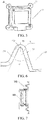
- the flexible radar support 100 when an automobile vibrates, thanks to the special design of the U-shaped cantilever beams 13, and the fact that the radar 200 itself has a certain weight, the flexible radar support 100 absorbs part of the vibrations by means of the weight of the radar itself and the flexibility of the U-shapes. During this process, as illustrated by the dotted line in Figure 7 , the flexible radar support 100 undergoes only slight deformation, thereby reducing to the maximum extent the impact of an automobile body's vibrations on the detection precision of a radar.
Landscapes
- Engineering & Computer Science (AREA)
- Radar, Positioning & Navigation (AREA)
- Remote Sensing (AREA)
- Physics & Mathematics (AREA)
- Computer Networks & Wireless Communication (AREA)
- General Physics & Mathematics (AREA)
- Electromagnetism (AREA)
- Radar Systems Or Details Thereof (AREA)
- Vibration Dampers (AREA)
Abstract
Description
- The invention relates to the field of radar support, and more particularly, to a flexible radar support that absorbs vibration deviation.
- Currently, consumers of automobiles have higher and higher requirements for functions of an automobile. Various types of high-end radars are used more and more. Regarding bumpers, radars of various functions are integrated with a bumper, which not only enhances the functionality of the bumper, but also increases the value of the bumper. However, after a radar is integrated with a skin, during the course of driving, when unsmooth road conditions are encountered, vibrations of the skin will cause the radar to shake. Because the radars frequency bands used in automobiles are relatively high at this stage (for example, 77 GHz millimetre wave radar), it imposes relatively high requirements on the counterpart's stability. In particular regarding radars requiring high precision, during the course of driving, an automobile's vibrations have a certain impact on a radar's detection precision.
- Currently, high-precision radars are mostly integrated in automobile body frame or grille regions. Those regions usually can provide a relatively stable positioning system for a radar. During the course of driving, the impact on the radar is relatively small, but this has certain limitation on the arrangement of the radar.
- An objective of the invention is to provide a flexible radar support that absorbs vibration deviation, thus solving the problem in the prior art that the detection precision of a radar is affected by an automobile's vibrations.
- To solve the above-described technical problem, the invention adopts the following technical solution:
A flexible radar support for absorbing vibration deviation is provided. It comprises a support base and a support top cover that are engaged with each other in an interlocking manner. A housing space for arranging a radar is formed between the support base and the support top cover. The support base comprises: a centrally arranged base center, and a base edge circumferentially arranged around the base center. The base edge and the base center are connected through four flexible structures that form U-shaped cantilever beams protruding towards the support top cover. - Preferably, the four U-shaped cantilever beams are symmetrically arranged in four directions of up, down, left, and right directions, respectively.
- Preferably, four corner regions between the base edge and the base center are hollowed out and disconnected.
- Preferably, first protruding tabs, extending towards the base edge and keeping spaced from the base edge, are arranged in the four corner regions of the base center. The first protruding tabs are provided with screw holes.
- Preferably, second protruding tabs for cooperating with the first protruding tabs are arranged in four corner regions of the support top cover. The second protruding tabs are provided with screw holes.
- Preferably, the support base and the support top cover are fastened to each other by self-tapping screws.
- Preferably, the wall thickness of a side wall of the U-shaped cantilever beams is 2.0 mm to 3.0 mm.
- Preferably, the wall thickness of the bent portion of the U-shaped cantilever beams is 1.0 mm to 2.0 mm.
- Preferably, the radius of a round angle of a bent portion of the U-shaped cantilever beams is 3.5 mm to 4.5 mm.
- Preferably, the angle formed by two side walls of the U-shaped cantilever beams is 40° to 50°.
- With the flexible radar support provided by the invention, thanks to the design of U-shaped flexible structures, even in the situation where an automobile body vibrates at a large amplitude, the flexible radar support can still absorb swaying(shaking) in the up and down, and left and right directions during the course of driving, thereby reducing the impact of the automobile body's vibrations on the detection precision of a radar. Moreover, the flexible radar support can provide more choices for radar positions within the range of permitted arrangement for a radar, and at the same time enhances the functionality of a bumper.
-
Figure 1 is an overall assembled view of a flexible radar support in use state provided according to a preferred embodiment of the invention; -
Figure 2 is a sectional view of the structure shown inFigure 1 ; -
Figure 3 is a structural diagram of the support base; -
Figure 4 is a sectional view of the support base shown inFigure 3 ; -
Figure 5 is structural diagram of the support top cover; -
Figure 6 is a schematic enlarged detailed view of a U-shaped cantilever beam on a support base; -
Figure 7 is a schematic view of the states of the flexible radar support before and after deformation. - The invention will be described further below in reference to specific embodiments. It should be understood that the embodiments below are used merely to describe the invention and not to limit the scope of the invention.
- In reference to
Figures 1 and 2 , a schematic view of aflexible radar support 100 in use state provided according to a preferred embodiment of the invention is shown. Theflexible radar support 100 comprises asupport base 1 and a support top cover 2 that are engaged with each other in an interlocking manner. Aradar 200 is arranged in a housing space formed between thesupport base 1 and the support top cover 2. - Specifically, in reference to
Figures 3 and 4 , thesupport base 1 comprises: a centrally arrangedbase center 12, and abase edge 11 provided circumferentially around thebase center 12. Thebase edge 11 and thebase center 12 are connected through four flexible structures that formU-shaped cantilever beams 13 protruding towards the support top cover 2. By providing the U-shapedcantilever beams 13, theflexible radar support 100 can absorb vibration deviations caused by an automobile body skin, reducing the impact of the skin's vibrations on the detection precision of theradar 200. - According to the preferred embodiment, the four
U-shaped cantilever beams 13 are arranged symmetrically in the respective four-upward, downward, left, and right-directions. Four corner regions between thebase edge 11 and thebase center 12 are hollowed out and disconnected. - According to this preferred embodiment, first protruding
tabs 14, extending towards thebase edge 11 and keeping spaced from thebase edge 11, are arranged in the four corner regions of thebase center 12. Thefirst protruding tabs 14 are provided withscrew holes 15. - As shown in
Figure 5 , correspondingly,second protruding tabs 21 for cooperating with thefirst protruding tabs 14 are provided in the four corner regions of the support top cover 2. Thesecond protruding tabs 21 are also provided withscrew holes 22. - Therefore, according to this preferred embodiment, the fixing between the
support base 1 and the support top cover 2 that engage with each other in an interlocking manner can be achieved by self-tapping screws that pass through thescrew holes - According to the invention, as shown in
Figure 6 , the wall thickness T1 of thebent portion 132 of theU-shaped cantilever beams 13 is preferably 1.0 mm to 2.0 mm. - Thee wall thickness T2 of the
side wall 131 of theU-shaped cantilever beams 13 is preferably 2.0 mm to 3.0 mm. - The radius R of the round angle of the
bent portion 132 of theU-shaped cantilever beams 13 is preferably 3.5 mm to 4.5 mm. - The angle α formed between the two
side walls 131 of theU-shaped cantilever beams 13 is preferably 40° to 50°. - The "U"-
shaped cantilever beams 13 can be adapted to different weights of the radar by changing the wall thickness, the angle formed between the two side walls, the size of the "U"-shape, and the kind of material. - According to this preferred embodiment, the wall thickness T1 of the
bent portion 132 of theU-shaped cantilever beams 13 is 1.5 mm, the wall thickness T2 of theside wall 131 is 2.5 mm, the radius R of the round angle of thebent portion 132 is 4.0 mm, and the angle α formed by the twoside walls 131 is 43°. - With the
flexible radar support 100 provided according to the above-described preferred embodiment, when an automobile vibrates, thanks to the special design of the U-shapedcantilever beams 13, and the fact that theradar 200 itself has a certain weight, theflexible radar support 100 absorbs part of the vibrations by means of the weight of the radar itself and the flexibility of the U-shapes. During this process, as illustrated by the dotted line inFigure 7 , theflexible radar support 100 undergoes only slight deformation, thereby reducing to the maximum extent the impact of an automobile body's vibrations on the detection precision of a radar. - What has been described are merely preferred embodiments of the invention, and are not intended to limit the scope of the invention. The embodiments of the invention described above can be subject to various modifications. All simple, equivalent changes and embellishments made according to the claims and the contents of the specification of the present invention application fall within the scope of protection of the invention. What has not been described in detail in the invention is conventional technologies.
Claims (10)
- A flexible radar support for absorbing vibration deviation, characterized in that, it comprises a support base (1) and a support top cover (2) that are engaged with each other in an interlocking manner, a housing space for arranging a radar (200) being formed between the support base (1) and the support top cover (2), the support base (1) comprising: a centrally arranged base center (12), and a base edge (11) circumferentially arranged around the base center (12), the base edge (11) and the base center (12) being connected through four flexible structures that form U-shaped cantilever beams (13) protruding towards the support top cover (2).
- The flexible radar support according to claim 1, wherein the four U-shaped cantilever beams (13) are symmetrically arranged in four directions of up, down, left, and right directions, respectively.
- The flexible radar support according any one of the previous claims, wherein four corner regions between the base edge (11) and the base center (12) are hollowed out and disconnected.
- The flexible radar support according to claim 3, wherein first protruding tabs (14), extending towards the base edge (11) and keeping spaced from the base edge (11), are arranged in the four corner regions of the base center (12), the first protruding tabs (14) being provided with screw holes (15).
- The flexible radar support according to claim 4, wherein second protruding tabs (21) for cooperating with the first protruding tabs (14) are arranged in four corner regions of the support top cover (2), the second protruding tabs (21) being provided with screw holes (22).
- The flexible radar support according to claim 5, wherein the support base (1) and the support top cover (2) are fastened to each other by self-tapping screws.
- The flexible radar support according to any one of the previous claims, wherein the wall thickness of a side wall (131) of the U-shaped cantilever beams (13) is 2.0 mm to 3.0 mm.
- The flexible radar support according to any one of the previous claims, wherein the wall thickness of a bent portion (132) of the U-shaped cantilever beams (13) is 1.0 mm to 2.0 mm.
- The flexible radar support according to any one of the previous claims, wherein the radius of a round angle of a bent portion (132) of the U-shaped cantilever beams (13) is 3.5 mm to 4.5 mm.
- The flexible radar support according to any one of the previous claims, wherein the angle formed by two side walls (131) of the U-shaped cantilever beams (13) is 40° to 50°.
Applications Claiming Priority (1)
| Application Number | Priority Date | Filing Date | Title |
|---|---|---|---|
| CN201921542129.XU CN210478550U (en) | 2019-09-17 | 2019-09-17 | A Flexible Radar Mount That Absorbs Vibration Deviation |
Publications (2)
| Publication Number | Publication Date |
|---|---|
| EP3796044A1 true EP3796044A1 (en) | 2021-03-24 |
| EP3796044B1 EP3796044B1 (en) | 2023-09-20 |
Family
ID=70540411
Family Applications (1)
| Application Number | Title | Priority Date | Filing Date |
|---|---|---|---|
| EP19219689.7A Active EP3796044B1 (en) | 2019-09-17 | 2019-12-24 | A flexible radar support for absorbing vibration deviation |
Country Status (3)
| Country | Link |
|---|---|
| US (1) | US11681012B2 (en) |
| EP (1) | EP3796044B1 (en) |
| CN (1) | CN210478550U (en) |
Citations (4)
| Publication number | Priority date | Publication date | Assignee | Title |
|---|---|---|---|---|
| FR3037017A1 (en) * | 2015-06-05 | 2016-12-09 | Renault Sa | RADAR SUPPORT FOR VEHICLE |
| KR101879403B1 (en) * | 2018-01-17 | 2018-07-18 | 엘아이지넥스원 주식회사 | Vibration Reduction Transportation Apparatus for Long Range Radar Antenna and Vibration Reduction Transportation for Foldable Antenna Apparatus |
| US20180236958A1 (en) * | 2017-02-21 | 2018-08-23 | Mitsubishi Jidosha Kogyo Kabushiki Kaisha | Structure for mounting radar |
| US20180347656A1 (en) * | 2017-03-27 | 2018-12-06 | Hutchinson Aerospace & Industry, Inc. | Continuous framework for shock, vibration and thermal isolation and motion accommodation |
Family Cites Families (3)
| Publication number | Priority date | Publication date | Assignee | Title |
|---|---|---|---|---|
| DE102010027503B4 (en) * | 2009-07-17 | 2025-01-23 | Huf Hülsbeck & Fürst Gmbh & Co. Kg | Rear camera device and method for actuating a movable part of a motor vehicle |
| US20140104049A1 (en) * | 2012-10-17 | 2014-04-17 | Mark Foss | Self-Contained, Obstacle Detection Assembly and Alert System |
| US10797384B2 (en) * | 2017-12-22 | 2020-10-06 | Nissan North America, Inc. | Radar support structure |
-
2019
- 2019-09-17 CN CN201921542129.XU patent/CN210478550U/en active Active
- 2019-12-24 EP EP19219689.7A patent/EP3796044B1/en active Active
- 2019-12-27 US US16/728,807 patent/US11681012B2/en active Active
Patent Citations (4)
| Publication number | Priority date | Publication date | Assignee | Title |
|---|---|---|---|---|
| FR3037017A1 (en) * | 2015-06-05 | 2016-12-09 | Renault Sa | RADAR SUPPORT FOR VEHICLE |
| US20180236958A1 (en) * | 2017-02-21 | 2018-08-23 | Mitsubishi Jidosha Kogyo Kabushiki Kaisha | Structure for mounting radar |
| US20180347656A1 (en) * | 2017-03-27 | 2018-12-06 | Hutchinson Aerospace & Industry, Inc. | Continuous framework for shock, vibration and thermal isolation and motion accommodation |
| KR101879403B1 (en) * | 2018-01-17 | 2018-07-18 | 엘아이지넥스원 주식회사 | Vibration Reduction Transportation Apparatus for Long Range Radar Antenna and Vibration Reduction Transportation for Foldable Antenna Apparatus |
Also Published As
| Publication number | Publication date |
|---|---|
| CN210478550U (en) | 2020-05-08 |
| EP3796044B1 (en) | 2023-09-20 |
| US20210080538A1 (en) | 2021-03-18 |
| US11681012B2 (en) | 2023-06-20 |
Similar Documents
| Publication | Publication Date | Title |
|---|---|---|
| US9804261B2 (en) | Vehicle radar installation structure and fascia retainer | |
| EP2873592B1 (en) | Front spoiler device | |
| EP3032138B1 (en) | Vibration damping device | |
| EP3184853B1 (en) | Vibration isolation device | |
| JP2009248816A (en) | Resinous impact-shock absorber for side impact | |
| US20130141269A1 (en) | Device for Fastening a Sensor Assembly, Especially a Radar Sensor | |
| JP2016121927A (en) | Object detection device | |
| EP2940796A1 (en) | Antenna apparatus | |
| CN104228961B (en) | Vehicle front body structure | |
| EP2759004B1 (en) | Battery mounting structure | |
| EP3796044B1 (en) | A flexible radar support for absorbing vibration deviation | |
| US9738241B2 (en) | Bumper absorber attachment structure | |
| JP2015000651A (en) | Fuel tank | |
| JP2022524518A (en) | Frequency-tuned vibration damper device, its manufacturing method, and vibration damper assembly including the device. | |
| EP3471436B1 (en) | Speaker unit, electronic equipment and mobile object device | |
| CN110588557B (en) | Radar bracket and vehicle | |
| US9751480B1 (en) | Crush box for vehicle impact | |
| WO2015048057A1 (en) | Bumper assembly | |
| JP6095789B2 (en) | Automotive radar equipment | |
| EP4112971A1 (en) | Anti-vibration device | |
| CN223348285U (en) | Ship four-hole military cable vibration reduction device | |
| CN108349364B (en) | Device for attaching a drive train | |
| JP3113726B2 (en) | Liquid-filled mount | |
| JP6476509B2 (en) | Object detection device | |
| JP2023143210A (en) | Reflection suppressing material for radar equipment |
Legal Events
| Date | Code | Title | Description |
|---|---|---|---|
| PUAI | Public reference made under article 153(3) epc to a published international application that has entered the european phase |
Free format text: ORIGINAL CODE: 0009012 |
|
| STAA | Information on the status of an ep patent application or granted ep patent |
Free format text: STATUS: THE APPLICATION HAS BEEN PUBLISHED |
|
| AK | Designated contracting states |
Kind code of ref document: A1 Designated state(s): AL AT BE BG CH CY CZ DE DK EE ES FI FR GB GR HR HU IE IS IT LI LT LU LV MC MK MT NL NO PL PT RO RS SE SI SK SM TR |
|
| AX | Request for extension of the european patent |
Extension state: BA ME |
|
| STAA | Information on the status of an ep patent application or granted ep patent |
Free format text: STATUS: REQUEST FOR EXAMINATION WAS MADE |
|
| 17P | Request for examination filed |
Effective date: 20210914 |
|
| RBV | Designated contracting states (corrected) |
Designated state(s): AL AT BE BG CH CY CZ DE DK EE ES FI FR GB GR HR HU IE IS IT LI LT LU LV MC MK MT NL NO PL PT RO RS SE SI SK SM TR |
|
| STAA | Information on the status of an ep patent application or granted ep patent |
Free format text: STATUS: EXAMINATION IS IN PROGRESS |
|
| 17Q | First examination report despatched |
Effective date: 20220914 |
|
| GRAP | Despatch of communication of intention to grant a patent |
Free format text: ORIGINAL CODE: EPIDOSNIGR1 |
|
| STAA | Information on the status of an ep patent application or granted ep patent |
Free format text: STATUS: GRANT OF PATENT IS INTENDED |
|
| INTG | Intention to grant announced |
Effective date: 20230421 |
|
| P01 | Opt-out of the competence of the unified patent court (upc) registered |
Effective date: 20230525 |
|
| GRAS | Grant fee paid |
Free format text: ORIGINAL CODE: EPIDOSNIGR3 |
|
| GRAA | (expected) grant |
Free format text: ORIGINAL CODE: 0009210 |
|
| STAA | Information on the status of an ep patent application or granted ep patent |
Free format text: STATUS: THE PATENT HAS BEEN GRANTED |
|
| AK | Designated contracting states |
Kind code of ref document: B1 Designated state(s): AL AT BE BG CH CY CZ DE DK EE ES FI FR GB GR HR HU IE IS IT LI LT LU LV MC MK MT NL NO PL PT RO RS SE SI SK SM TR |
|
| REG | Reference to a national code |
Ref country code: GB Ref legal event code: FG4D |
|
| REG | Reference to a national code |
Ref country code: CH Ref legal event code: EP |
|
| REG | Reference to a national code |
Ref country code: IE Ref legal event code: FG4D |
|
| REG | Reference to a national code |
Ref country code: DE Ref legal event code: R096 Ref document number: 602019037760 Country of ref document: DE |
|
| REG | Reference to a national code |
Ref country code: LT Ref legal event code: MG9D |
|
| PG25 | Lapsed in a contracting state [announced via postgrant information from national office to epo] |
Ref country code: GR Free format text: LAPSE BECAUSE OF FAILURE TO SUBMIT A TRANSLATION OF THE DESCRIPTION OR TO PAY THE FEE WITHIN THE PRESCRIBED TIME-LIMIT Effective date: 20231221 |
|
| REG | Reference to a national code |
Ref country code: NL Ref legal event code: MP Effective date: 20230920 |
|
| PG25 | Lapsed in a contracting state [announced via postgrant information from national office to epo] |
Ref country code: SE Free format text: LAPSE BECAUSE OF FAILURE TO SUBMIT A TRANSLATION OF THE DESCRIPTION OR TO PAY THE FEE WITHIN THE PRESCRIBED TIME-LIMIT Effective date: 20230920 Ref country code: RS Free format text: LAPSE BECAUSE OF FAILURE TO SUBMIT A TRANSLATION OF THE DESCRIPTION OR TO PAY THE FEE WITHIN THE PRESCRIBED TIME-LIMIT Effective date: 20230920 Ref country code: NO Free format text: LAPSE BECAUSE OF FAILURE TO SUBMIT A TRANSLATION OF THE DESCRIPTION OR TO PAY THE FEE WITHIN THE PRESCRIBED TIME-LIMIT Effective date: 20231220 Ref country code: LV Free format text: LAPSE BECAUSE OF FAILURE TO SUBMIT A TRANSLATION OF THE DESCRIPTION OR TO PAY THE FEE WITHIN THE PRESCRIBED TIME-LIMIT Effective date: 20230920 Ref country code: LT Free format text: LAPSE BECAUSE OF FAILURE TO SUBMIT A TRANSLATION OF THE DESCRIPTION OR TO PAY THE FEE WITHIN THE PRESCRIBED TIME-LIMIT Effective date: 20230920 Ref country code: HR Free format text: LAPSE BECAUSE OF FAILURE TO SUBMIT A TRANSLATION OF THE DESCRIPTION OR TO PAY THE FEE WITHIN THE PRESCRIBED TIME-LIMIT Effective date: 20230920 Ref country code: GR Free format text: LAPSE BECAUSE OF FAILURE TO SUBMIT A TRANSLATION OF THE DESCRIPTION OR TO PAY THE FEE WITHIN THE PRESCRIBED TIME-LIMIT Effective date: 20231221 Ref country code: FI Free format text: LAPSE BECAUSE OF FAILURE TO SUBMIT A TRANSLATION OF THE DESCRIPTION OR TO PAY THE FEE WITHIN THE PRESCRIBED TIME-LIMIT Effective date: 20230920 |
|
| REG | Reference to a national code |
Ref country code: AT Ref legal event code: MK05 Ref document number: 1613798 Country of ref document: AT Kind code of ref document: T Effective date: 20230920 |
|
| PG25 | Lapsed in a contracting state [announced via postgrant information from national office to epo] |
Ref country code: NL Free format text: LAPSE BECAUSE OF FAILURE TO SUBMIT A TRANSLATION OF THE DESCRIPTION OR TO PAY THE FEE WITHIN THE PRESCRIBED TIME-LIMIT Effective date: 20230920 |
|
| PG25 | Lapsed in a contracting state [announced via postgrant information from national office to epo] |
Ref country code: IS Free format text: LAPSE BECAUSE OF FAILURE TO SUBMIT A TRANSLATION OF THE DESCRIPTION OR TO PAY THE FEE WITHIN THE PRESCRIBED TIME-LIMIT Effective date: 20240120 |
|
| PG25 | Lapsed in a contracting state [announced via postgrant information from national office to epo] |
Ref country code: AT Free format text: LAPSE BECAUSE OF FAILURE TO SUBMIT A TRANSLATION OF THE DESCRIPTION OR TO PAY THE FEE WITHIN THE PRESCRIBED TIME-LIMIT Effective date: 20230920 |
|
| PG25 | Lapsed in a contracting state [announced via postgrant information from national office to epo] |
Ref country code: ES Free format text: LAPSE BECAUSE OF FAILURE TO SUBMIT A TRANSLATION OF THE DESCRIPTION OR TO PAY THE FEE WITHIN THE PRESCRIBED TIME-LIMIT Effective date: 20230920 |
|
| PG25 | Lapsed in a contracting state [announced via postgrant information from national office to epo] |
Ref country code: SM Free format text: LAPSE BECAUSE OF FAILURE TO SUBMIT A TRANSLATION OF THE DESCRIPTION OR TO PAY THE FEE WITHIN THE PRESCRIBED TIME-LIMIT Effective date: 20230920 Ref country code: RO Free format text: LAPSE BECAUSE OF FAILURE TO SUBMIT A TRANSLATION OF THE DESCRIPTION OR TO PAY THE FEE WITHIN THE PRESCRIBED TIME-LIMIT Effective date: 20230920 Ref country code: IS Free format text: LAPSE BECAUSE OF FAILURE TO SUBMIT A TRANSLATION OF THE DESCRIPTION OR TO PAY THE FEE WITHIN THE PRESCRIBED TIME-LIMIT Effective date: 20240120 Ref country code: ES Free format text: LAPSE BECAUSE OF FAILURE TO SUBMIT A TRANSLATION OF THE DESCRIPTION OR TO PAY THE FEE WITHIN THE PRESCRIBED TIME-LIMIT Effective date: 20230920 Ref country code: EE Free format text: LAPSE BECAUSE OF FAILURE TO SUBMIT A TRANSLATION OF THE DESCRIPTION OR TO PAY THE FEE WITHIN THE PRESCRIBED TIME-LIMIT Effective date: 20230920 Ref country code: CZ Free format text: LAPSE BECAUSE OF FAILURE TO SUBMIT A TRANSLATION OF THE DESCRIPTION OR TO PAY THE FEE WITHIN THE PRESCRIBED TIME-LIMIT Effective date: 20230920 Ref country code: AT Free format text: LAPSE BECAUSE OF FAILURE TO SUBMIT A TRANSLATION OF THE DESCRIPTION OR TO PAY THE FEE WITHIN THE PRESCRIBED TIME-LIMIT Effective date: 20230920 Ref country code: SK Free format text: LAPSE BECAUSE OF FAILURE TO SUBMIT A TRANSLATION OF THE DESCRIPTION OR TO PAY THE FEE WITHIN THE PRESCRIBED TIME-LIMIT Effective date: 20230920 Ref country code: PT Free format text: LAPSE BECAUSE OF FAILURE TO SUBMIT A TRANSLATION OF THE DESCRIPTION OR TO PAY THE FEE WITHIN THE PRESCRIBED TIME-LIMIT Effective date: 20240122 |
|
| PG25 | Lapsed in a contracting state [announced via postgrant information from national office to epo] |
Ref country code: PL Free format text: LAPSE BECAUSE OF FAILURE TO SUBMIT A TRANSLATION OF THE DESCRIPTION OR TO PAY THE FEE WITHIN THE PRESCRIBED TIME-LIMIT Effective date: 20230920 Ref country code: IT Free format text: LAPSE BECAUSE OF FAILURE TO SUBMIT A TRANSLATION OF THE DESCRIPTION OR TO PAY THE FEE WITHIN THE PRESCRIBED TIME-LIMIT Effective date: 20230920 |
|
| REG | Reference to a national code |
Ref country code: DE Ref legal event code: R097 Ref document number: 602019037760 Country of ref document: DE |
|
| PG25 | Lapsed in a contracting state [announced via postgrant information from national office to epo] |
Ref country code: DK Free format text: LAPSE BECAUSE OF FAILURE TO SUBMIT A TRANSLATION OF THE DESCRIPTION OR TO PAY THE FEE WITHIN THE PRESCRIBED TIME-LIMIT Effective date: 20230920 |
|
| PLBE | No opposition filed within time limit |
Free format text: ORIGINAL CODE: 0009261 |
|
| STAA | Information on the status of an ep patent application or granted ep patent |
Free format text: STATUS: NO OPPOSITION FILED WITHIN TIME LIMIT |
|
| PG25 | Lapsed in a contracting state [announced via postgrant information from national office to epo] |
Ref country code: DK Free format text: LAPSE BECAUSE OF FAILURE TO SUBMIT A TRANSLATION OF THE DESCRIPTION OR TO PAY THE FEE WITHIN THE PRESCRIBED TIME-LIMIT Effective date: 20230920 |
|
| REG | Reference to a national code |
Ref country code: CH Ref legal event code: PL |
|
| RAP4 | Party data changed (patent owner data changed or rights of a patent transferred) |
Owner name: OPMOBILITY SE Owner name: YANFENG PLASTIC OMNIUMAUTOMOTIVE EXTERIOR SYSTEMS CO., LTD. |
|
| PG25 | Lapsed in a contracting state [announced via postgrant information from national office to epo] |
Ref country code: LU Free format text: LAPSE BECAUSE OF NON-PAYMENT OF DUE FEES Effective date: 20231224 |
|
| PG25 | Lapsed in a contracting state [announced via postgrant information from national office to epo] |
Ref country code: MC Free format text: LAPSE BECAUSE OF FAILURE TO SUBMIT A TRANSLATION OF THE DESCRIPTION OR TO PAY THE FEE WITHIN THE PRESCRIBED TIME-LIMIT Effective date: 20230920 |
|
| 26N | No opposition filed |
Effective date: 20240621 |
|
| REG | Reference to a national code |
Ref country code: BE Ref legal event code: MM Effective date: 20231231 |
|
| PG25 | Lapsed in a contracting state [announced via postgrant information from national office to epo] |
Ref country code: MC Free format text: LAPSE BECAUSE OF FAILURE TO SUBMIT A TRANSLATION OF THE DESCRIPTION OR TO PAY THE FEE WITHIN THE PRESCRIBED TIME-LIMIT Effective date: 20230920 Ref country code: LU Free format text: LAPSE BECAUSE OF NON-PAYMENT OF DUE FEES Effective date: 20231224 |
|
| REG | Reference to a national code |
Ref country code: DE Ref legal event code: R081 Ref document number: 602019037760 Country of ref document: DE Owner name: YANFENG PLASTIC OMNIUM AUTOMOTIVE EXTERIOR SYS, CN Free format text: FORMER OWNERS: COMPAGNIE PLASTIC OMNIUM SE, LYON, FR; YANFENG PLASTIC OMNIUM AUTOMOTIVE EXTERIOR SYSTEMS CO., LTD., SHANGHAI, CN Ref country code: DE Ref legal event code: R081 Ref document number: 602019037760 Country of ref document: DE Owner name: OPMOBILITY SE, FR Free format text: FORMER OWNERS: COMPAGNIE PLASTIC OMNIUM SE, LYON, FR; YANFENG PLASTIC OMNIUM AUTOMOTIVE EXTERIOR SYSTEMS CO., LTD., SHANGHAI, CN |
|
| REG | Reference to a national code |
Ref country code: IE Ref legal event code: MM4A |
|
| PG25 | Lapsed in a contracting state [announced via postgrant information from national office to epo] |
Ref country code: IE Free format text: LAPSE BECAUSE OF NON-PAYMENT OF DUE FEES Effective date: 20231224 |
|
| PG25 | Lapsed in a contracting state [announced via postgrant information from national office to epo] |
Ref country code: BE Free format text: LAPSE BECAUSE OF NON-PAYMENT OF DUE FEES Effective date: 20231231 |
|
| PG25 | Lapsed in a contracting state [announced via postgrant information from national office to epo] |
Ref country code: CH Free format text: LAPSE BECAUSE OF NON-PAYMENT OF DUE FEES Effective date: 20231231 |
|
| PG25 | Lapsed in a contracting state [announced via postgrant information from national office to epo] |
Ref country code: SI Free format text: LAPSE BECAUSE OF FAILURE TO SUBMIT A TRANSLATION OF THE DESCRIPTION OR TO PAY THE FEE WITHIN THE PRESCRIBED TIME-LIMIT Effective date: 20230920 |
|
| PG25 | Lapsed in a contracting state [announced via postgrant information from national office to epo] |
Ref country code: SI Free format text: LAPSE BECAUSE OF FAILURE TO SUBMIT A TRANSLATION OF THE DESCRIPTION OR TO PAY THE FEE WITHIN THE PRESCRIBED TIME-LIMIT Effective date: 20230920 Ref country code: IE Free format text: LAPSE BECAUSE OF NON-PAYMENT OF DUE FEES Effective date: 20231224 Ref country code: CH Free format text: LAPSE BECAUSE OF NON-PAYMENT OF DUE FEES Effective date: 20231231 Ref country code: BE Free format text: LAPSE BECAUSE OF NON-PAYMENT OF DUE FEES Effective date: 20231231 |
|
| PG25 | Lapsed in a contracting state [announced via postgrant information from national office to epo] |
Ref country code: BG Free format text: LAPSE BECAUSE OF FAILURE TO SUBMIT A TRANSLATION OF THE DESCRIPTION OR TO PAY THE FEE WITHIN THE PRESCRIBED TIME-LIMIT Effective date: 20230920 |
|
| PG25 | Lapsed in a contracting state [announced via postgrant information from national office to epo] |
Ref country code: BG Free format text: LAPSE BECAUSE OF FAILURE TO SUBMIT A TRANSLATION OF THE DESCRIPTION OR TO PAY THE FEE WITHIN THE PRESCRIBED TIME-LIMIT Effective date: 20230920 |
|
| PG25 | Lapsed in a contracting state [announced via postgrant information from national office to epo] |
Ref country code: CY Free format text: LAPSE BECAUSE OF FAILURE TO SUBMIT A TRANSLATION OF THE DESCRIPTION OR TO PAY THE FEE WITHIN THE PRESCRIBED TIME-LIMIT; INVALID AB INITIO Effective date: 20191224 |
|
| PG25 | Lapsed in a contracting state [announced via postgrant information from national office to epo] |
Ref country code: HU Free format text: LAPSE BECAUSE OF FAILURE TO SUBMIT A TRANSLATION OF THE DESCRIPTION OR TO PAY THE FEE WITHIN THE PRESCRIBED TIME-LIMIT; INVALID AB INITIO Effective date: 20191224 |
|
| PG25 | Lapsed in a contracting state [announced via postgrant information from national office to epo] |
Ref country code: TR Free format text: LAPSE BECAUSE OF FAILURE TO SUBMIT A TRANSLATION OF THE DESCRIPTION OR TO PAY THE FEE WITHIN THE PRESCRIBED TIME-LIMIT Effective date: 20230920 |
|
| PGFP | Annual fee paid to national office [announced via postgrant information from national office to epo] |
Ref country code: DE Payment date: 20251211 Year of fee payment: 7 |
|
| PGFP | Annual fee paid to national office [announced via postgrant information from national office to epo] |
Ref country code: GB Payment date: 20251219 Year of fee payment: 7 |
|
| PGFP | Annual fee paid to national office [announced via postgrant information from national office to epo] |
Ref country code: FR Payment date: 20251230 Year of fee payment: 7 |