EP3796030A1 - Radar bracket with surface self-adaptiveness - Google Patents
Radar bracket with surface self-adaptiveness Download PDFInfo
- Publication number
- EP3796030A1 EP3796030A1 EP19219685.5A EP19219685A EP3796030A1 EP 3796030 A1 EP3796030 A1 EP 3796030A1 EP 19219685 A EP19219685 A EP 19219685A EP 3796030 A1 EP3796030 A1 EP 3796030A1
- Authority
- EP
- European Patent Office
- Prior art keywords
- bracket
- radar
- flanging
- skin
- self
- Prior art date
- Legal status (The legal status is an assumption and is not a legal conclusion. Google has not performed a legal analysis and makes no representation as to the accuracy of the status listed.)
- Ceased
Links
Images

Classifications
-
- H—ELECTRICITY
- H01—ELECTRIC ELEMENTS
- H01Q—ANTENNAS, i.e. RADIO AERIALS
- H01Q1/00—Details of, or arrangements associated with, antennas
- H01Q1/12—Supports; Mounting means
-
- B—PERFORMING OPERATIONS; TRANSPORTING
- B60—VEHICLES IN GENERAL
- B60R—VEHICLES, VEHICLE FITTINGS, OR VEHICLE PARTS, NOT OTHERWISE PROVIDED FOR
- B60R19/00—Wheel guards; Radiator guards, e.g. grilles; Obstruction removers; Fittings damping bouncing force in collisions
- B60R19/02—Bumpers, i.e. impact receiving or absorbing members for protecting vehicles or fending off blows from other vehicles or objects
- B60R19/48—Bumpers, i.e. impact receiving or absorbing members for protecting vehicles or fending off blows from other vehicles or objects combined with, or convertible into, other devices or objects, e.g. bumpers combined with road brushes, bumpers convertible into beds
- B60R19/483—Bumpers, i.e. impact receiving or absorbing members for protecting vehicles or fending off blows from other vehicles or objects combined with, or convertible into, other devices or objects, e.g. bumpers combined with road brushes, bumpers convertible into beds with obstacle sensors of electric or electronic type
-
- G—PHYSICS
- G01—MEASURING; TESTING
- G01S—RADIO DIRECTION-FINDING; RADIO NAVIGATION; DETERMINING DISTANCE OR VELOCITY BY USE OF RADIO WAVES; LOCATING OR PRESENCE-DETECTING BY USE OF THE REFLECTION OR RERADIATION OF RADIO WAVES; ANALOGOUS ARRANGEMENTS USING OTHER WAVES
- G01S13/00—Systems using the reflection or reradiation of radio waves, e.g. radar systems; Analogous systems using reflection or reradiation of waves whose nature or wavelength is irrelevant or unspecified
- G01S13/88—Radar or analogous systems specially adapted for specific applications
- G01S13/93—Radar or analogous systems specially adapted for specific applications for anti-collision purposes
- G01S13/931—Radar or analogous systems specially adapted for specific applications for anti-collision purposes of land vehicles
-
- G—PHYSICS
- G01—MEASURING; TESTING
- G01S—RADIO DIRECTION-FINDING; RADIO NAVIGATION; DETERMINING DISTANCE OR VELOCITY BY USE OF RADIO WAVES; LOCATING OR PRESENCE-DETECTING BY USE OF THE REFLECTION OR RERADIATION OF RADIO WAVES; ANALOGOUS ARRANGEMENTS USING OTHER WAVES
- G01S7/00—Details of systems according to groups G01S13/00, G01S15/00, G01S17/00
- G01S7/02—Details of systems according to groups G01S13/00, G01S15/00, G01S17/00 of systems according to group G01S13/00
- G01S7/027—Constructional details of housings, e.g. form, type, material or ruggedness
-
- H—ELECTRICITY
- H01—ELECTRIC ELEMENTS
- H01Q—ANTENNAS, i.e. RADIO AERIALS
- H01Q1/00—Details of, or arrangements associated with, antennas
- H01Q1/27—Adaptation for use in or on movable bodies
- H01Q1/32—Adaptation for use in or on road or rail vehicles
- H01Q1/3208—Adaptation for use in or on road or rail vehicles characterised by the application wherein the antenna is used
- H01Q1/3233—Adaptation for use in or on road or rail vehicles characterised by the application wherein the antenna is used particular used as part of a sensor or in a security system, e.g. for automotive radar, navigation systems
-
- G—PHYSICS
- G01—MEASURING; TESTING
- G01S—RADIO DIRECTION-FINDING; RADIO NAVIGATION; DETERMINING DISTANCE OR VELOCITY BY USE OF RADIO WAVES; LOCATING OR PRESENCE-DETECTING BY USE OF THE REFLECTION OR RERADIATION OF RADIO WAVES; ANALOGOUS ARRANGEMENTS USING OTHER WAVES
- G01S13/00—Systems using the reflection or reradiation of radio waves, e.g. radar systems; Analogous systems using reflection or reradiation of waves whose nature or wavelength is irrelevant or unspecified
- G01S13/88—Radar or analogous systems specially adapted for specific applications
- G01S13/93—Radar or analogous systems specially adapted for specific applications for anti-collision purposes
- G01S13/931—Radar or analogous systems specially adapted for specific applications for anti-collision purposes of land vehicles
- G01S2013/9327—Sensor installation details
-
- G—PHYSICS
- G01—MEASURING; TESTING
- G01S—RADIO DIRECTION-FINDING; RADIO NAVIGATION; DETERMINING DISTANCE OR VELOCITY BY USE OF RADIO WAVES; LOCATING OR PRESENCE-DETECTING BY USE OF THE REFLECTION OR RERADIATION OF RADIO WAVES; ANALOGOUS ARRANGEMENTS USING OTHER WAVES
- G01S13/00—Systems using the reflection or reradiation of radio waves, e.g. radar systems; Analogous systems using reflection or reradiation of waves whose nature or wavelength is irrelevant or unspecified
- G01S13/88—Radar or analogous systems specially adapted for specific applications
- G01S13/93—Radar or analogous systems specially adapted for specific applications for anti-collision purposes
- G01S13/931—Radar or analogous systems specially adapted for specific applications for anti-collision purposes of land vehicles
- G01S2013/9327—Sensor installation details
- G01S2013/93275—Sensor installation details in the bumper area
Definitions
- the invention relates to the field of radar bracket, and more particularly, to a radar bracket capable of self-adapting to a curved surface.
- Radars are a means of assisting driving, reversing, or parking, and are used more and more in current automobile models.
- radar brackets which serve as a carrier that connects a radar to a skin.
- the technical drawbacks currently existing are mainly: first, as various radar brackets need to be produced to adapt to the mounting of the same type radar at different positions, production costs are high; second, as whether the type of a radar bracket matches a position needs to be identified, which is time consuming and labor consuming, mounting costs are high; third, even though whether the type of a radar bracket matches a position is identified, the risk of erroneous mounting still exists.
- An objective of the invention is to provide a radar bracket capable of self-adapting to a curved surface, thus solving the problem in the prior art that radar brackets cannot be used universally all over an assembled automobile, which in turn results in various types of radar brackets, high production costs, high mounting costs, and the existence of the risk of erroneous mounting.
- a radar bracket capable of self-adapting to a curved surface comprises: a bracket body provided with a radar mounting part; and, a bracket flanging configured to be fixed to a skin and being arranged at a periphery of the bracket body.
- the bracket flanging is provided with a plurality of weakened structures for providing its self-adaptiveness to a curved surface.
- the weakened structures are slits formed by a hollowing-out operation.
- the slits are formed at a junction between the bracket flanging and the bracket body.
- the slits extend from a junction between the bracket flanging and the bracket body to a periphery of the bracket flanging.
- the slits extend from a periphery of the bracket flanging to a central area of the bracket flanging.
- the weakened structures are notches formed at a periphery of the bracket flanging by a hollowing-out operation.
- the bracket flanging is fixed to the skin by adhesive bonding or welding.
- the bracket flanging is in a curved sheet-like structure, and its curvature can be easily modified under an action of external force so as to adapt to a curvature of the skin.
- the radar bracket capable of self-adapting to a curved surface
- the radar bracket when the radar bracket is to be adhesively bonded or welded to a skin, it can easily deform to adapt to a curved surface of a counterpart by means of local surface self-adaptive structures of the bracket flanging. Therefore, the radar bracket can be attached to different positions with different curvatures of the skin, thereby achieving the objective that the radar bracket can be universally used all over an assembled automobile.
- the radar bracket provided by the invention can achieve the following functions: mounting integration of a same type radar by means of the radar bracket at different regions of a same automobile model; mounting integration of a same type radar by means of the radar bracket at different regions of a different automobile model.
- the invention provides a radar bracket with self-adaptiveness to a curved surface, which can be used universally all over an assembled automobile. Thanks to the radar bracket, the production costs, the mounting costs, and the probability of erroneous mounting are greatly reduced.
- the radar bracket 100 comprises: a bracket body 1, and a bracket flanging 2.
- the bracket body 1 is provided with a radar mounting part 11 for mounting a radar 10.
- the bracket flanging 2 is provided at the periphery of the bracket body 1, and is configured to being fixed with a skin 20 by adhesive bonding.
- the bracket flanging 2 is provided with a plurality of weakened structures to provide self-adaptability to a curved surface, that is, the ability of easily deform to adapt to various curved skins.
- the weakened structure is a slit formed by a hollowing-out operation.
- the slit comprises: a first slit structure 3 extending along the junction between the bracket flanging 2 and the bracket body 1.
- the first slit structure 3 is arranged symmetrically on both sides, left and right, of the bracket flanging 2, and extends a certain degree of curvature along the circumference of the joint between the bracket body 1 and the bracket flanging 2 respectively.
- the slit further comprises: a second slit structure 4 extending from the midpoint of the first slit structure 3 to an outer periphery of the bracket flanging 2.
- the second slit structure 4 is arranged symmetrically on both sides, left and right, of the bracket flanging 2, and extends respectively along a straight line.
- the bracket flanging 2 is in a curved sheet-like structure, and its curvature can be easily modified under an action of external force so as to adapt to a curvature of the skin 20.
- the process of mounting with the radar bracket 100 provided by this preferred embodiment is as follows: First, the radar 10 is mounted to the bracket body 1 by means of the radar mounting part 11, and then an adhesive tape 30 is adhered to the bottom of the bracket flanging 2, at this time, as shown in FIG. 2 , the bracket flanging 2 is in a tilted state;
- the bracket flanging 2 itself has the ability of self-adapting to a curved surface, the bracket flanging 2 can easily deform. Therefore, the radar bracket 100 mounted with the radar 10 can be bonded as a whole to a skin 20 by means of the adhesive tape 30. As shown in FIG. 3 , even if the curvature of the skin 20 is different at different positions, the radar bracket 100 can still be mounted properly.
- a radar bracket 200 provided according to another preferred embodiment of the invention.
- the radar bracket 200 is configured for mounting a radar 40, and comprises: a bracket body 201, and a bracket flanging 202.
- the bracket body 201 is provided with a radar mounting part 211 for mounting the radar 40.
- the bracket flanging 202 is arranged at the periphery of the bracket body 201, and is configured to be fixed on a skin 20 by welding.
- the bracket flanging 202 is provided with a plurality of weakened structures to provide its self-adaptation to a curved surface, that is, the ability of easily deform to adapt to various curved skins.
- the weakened structure comprises: slits and notches formed by a pierced operation.
- the slits comprise a third slit structure 203 extending from the outer periphery of the bracket flanging 202 to the central area of the bracket flanging 202.
- the notches comprise a V-shaped notch 204 formed by a hollowing-out operation at the edge of the outer periphery of the bracket flanging 202.
- notches are not limited to V-shape, and can be of any other appropriate form such as a U-shape.
- the process of mounting with the radar bracket 200 provided by this preferred embodiment is as follows: First, the radar 40 is mounted to the bracket body 201 by means of the radar mounting part 211, at that time, as shown in FIG. 5 , the bracket flanging 202 is in a tilted state;
- the bracket flanging 202 itself has the ability of self-adapting to a curved surface, the bracket flanging 202 can easily deform. Therefore, the radar bracket 200 mounted with the radar 40 can be bonded as a whole to a skin 20 by welding. As shown in FIG. 6 , even if the curvature of the skin 20 is different at different positions, the radar bracket 200 can still be mounted properly.
Landscapes
- Engineering & Computer Science (AREA)
- Radar, Positioning & Navigation (AREA)
- Remote Sensing (AREA)
- Physics & Mathematics (AREA)
- Computer Networks & Wireless Communication (AREA)
- General Physics & Mathematics (AREA)
- Computer Security & Cryptography (AREA)
- Mechanical Engineering (AREA)
- Electromagnetism (AREA)
- Radar Systems Or Details Thereof (AREA)
Abstract
Description
- The invention relates to the field of radar bracket, and more particularly, to a radar bracket capable of self-adapting to a curved surface.
- Radars are a means of assisting driving, reversing, or parking, and are used more and more in current automobile models. There are also an increasing number and more and more types of radar brackets, which serve as a carrier that connects a radar to a skin. The more functionality is equipped with an automobile model, the more radars there are, which means there are numerous radar brackets. This results in an important workload for the design phase, the project development phase, and the final component management. Therefore, the technical drawbacks currently existing are mainly: first, as various radar brackets need to be produced to adapt to the mounting of the same type radar at different positions, production costs are high; second, as whether the type of a radar bracket matches a position needs to be identified, which is time consuming and labor consuming, mounting costs are high; third, even though whether the type of a radar bracket matches a position is identified, the risk of erroneous mounting still exists.
- An objective of the invention is to provide a radar bracket capable of self-adapting to a curved surface, thus solving the problem in the prior art that radar brackets cannot be used universally all over an assembled automobile, which in turn results in various types of radar brackets, high production costs, high mounting costs, and the existence of the risk of erroneous mounting.
- To solve the above-described technical problems, the invention adopts the following technical solution:
A radar bracket capable of self-adapting to a curved surface is provided. The radar bracket comprises: a bracket body provided with a radar mounting part; and, a bracket flanging configured to be fixed to a skin and being arranged at a periphery of the bracket body. The bracket flanging is provided with a plurality of weakened structures for providing its self-adaptiveness to a curved surface. - Preferably, the weakened structures are slits formed by a hollowing-out operation.
- Preferably, the slits are formed at a junction between the bracket flanging and the bracket body.
- Preferably, the slits extend from a junction between the bracket flanging and the bracket body to a periphery of the bracket flanging.
- Preferably, the slits extend from a periphery of the bracket flanging to a central area of the bracket flanging.
- Preferably, the weakened structures are notches formed at a periphery of the bracket flanging by a hollowing-out operation.
- Preferably, the bracket flanging is fixed to the skin by adhesive bonding or welding.
- Preferably, the bracket flanging is in a curved sheet-like structure, and its curvature can be easily modified under an action of external force so as to adapt to a curvature of the skin.
- With the radar bracket capable of self-adapting to a curved surface provided by the invention, when the radar bracket is to be adhesively bonded or welded to a skin, it can easily deform to adapt to a curved surface of a counterpart by means of local surface self-adaptive structures of the bracket flanging. Therefore, the radar bracket can be attached to different positions with different curvatures of the skin, thereby achieving the objective that the radar bracket can be universally used all over an assembled automobile.
- Therefore, the radar bracket provided by the invention can achieve the following functions: mounting integration of a same type radar by means of the radar bracket at different regions of a same automobile model; mounting integration of a same type radar by means of the radar bracket at different regions of a different automobile model.
- In summary, the invention provides a radar bracket with self-adaptiveness to a curved surface, which can be used universally all over an assembled automobile. Thanks to the radar bracket, the production costs, the mounting costs, and the probability of erroneous mounting are greatly reduced.
-
-
FIG. 1 is a plan view of a radar bracket provided according to a preferred embodiment of the invention; -
FIG. 2 is a structural diagram of the radar bracket shown inFIG. 1 before being mounted to a skin; -
FIG. 3 is a structural diagram of the radar bracket as shown inFIG. 1 after being mounted to a skin; -
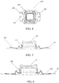
FIG. 4 is a plan view of a radar bracket provided according to another preferred embodiment of the invention; -
FIG. 5 is a structural diagram of the radar bracket as shown inFIG. 4 before being mounted to a skin; -
FIG. 6 is a structural diagram of the radar bracket as shown inFIG. 4 after being mounted to a skin. - The invention will be described further below in reference to specific embodiments. It should be understood that the following embodiments are used merely to describe the invention and not to limit the scope of the invention.
- In reference to
FIG. 1 to FIG. 3 , aradar bracket 100 provided according to a preferred embodiment of the invention is shown. Theradar bracket 100 comprises: abracket body 1, and a bracket flanging 2. Thebracket body 1 is provided with aradar mounting part 11 for mounting aradar 10. The bracket flanging 2 is provided at the periphery of thebracket body 1, and is configured to being fixed with askin 20 by adhesive bonding. The bracket flanging 2 is provided with a plurality of weakened structures to provide self-adaptability to a curved surface, that is, the ability of easily deform to adapt to various curved skins. - According to this preferred embodiment, the weakened structure is a slit formed by a hollowing-out operation. The slit comprises: a
first slit structure 3 extending along the junction between the bracket flanging 2 and thebracket body 1. Thefirst slit structure 3 is arranged symmetrically on both sides, left and right, of the bracket flanging 2, and extends a certain degree of curvature along the circumference of the joint between thebracket body 1 and the bracket flanging 2 respectively. - According to this preferred embodiment, the slit further comprises: a second slit structure 4 extending from the midpoint of the
first slit structure 3 to an outer periphery of the bracket flanging 2. The second slit structure 4 is arranged symmetrically on both sides, left and right, of the bracket flanging 2, and extends respectively along a straight line. - According to this preferred embodiment, the bracket flanging 2 is in a curved sheet-like structure, and its curvature can be easily modified under an action of external force so as to adapt to a curvature of the
skin 20. - The process of mounting with the
radar bracket 100 provided by this preferred embodiment is as follows:
First, theradar 10 is mounted to thebracket body 1 by means of theradar mounting part 11, and then anadhesive tape 30 is adhered to the bottom of the bracket flanging 2, at this time, as shown inFIG. 2 , the bracket flanging 2 is in a tilted state; - Next, because the bracket flanging 2 itself has the ability of self-adapting to a curved surface, the bracket flanging 2 can easily deform. Therefore, the
radar bracket 100 mounted with theradar 10 can be bonded as a whole to askin 20 by means of theadhesive tape 30. As shown inFIG. 3 , even if the curvature of theskin 20 is different at different positions, theradar bracket 100 can still be mounted properly. - In reference to
FIG. 4 to FIG. 6 , aradar bracket 200 provided according to another preferred embodiment of the invention is shown. Theradar bracket 200 is configured for mounting aradar 40, and comprises: abracket body 201, and a bracket flanging 202. Thebracket body 201 is provided with aradar mounting part 211 for mounting theradar 40. Thebracket flanging 202 is arranged at the periphery of thebracket body 201, and is configured to be fixed on askin 20 by welding. Thebracket flanging 202 is provided with a plurality of weakened structures to provide its self-adaptation to a curved surface, that is, the ability of easily deform to adapt to various curved skins. - According to this preferred embodiment, the weakened structure comprises: slits and notches formed by a pierced operation. The slits comprise a
third slit structure 203 extending from the outer periphery of the bracket flanging 202 to the central area of the bracket flanging 202. The notches comprise a V-shaped notch 204 formed by a hollowing-out operation at the edge of the outer periphery of the bracket flanging 202. - It should be understood that the notches are not limited to V-shape, and can be of any other appropriate form such as a U-shape.
- The process of mounting with the
radar bracket 200 provided by this preferred embodiment is as follows:
First, theradar 40 is mounted to thebracket body 201 by means of theradar mounting part 211, at that time, as shown inFIG. 5 , the bracket flanging 202 is in a tilted state; - Next, because the bracket flanging 202 itself has the ability of self-adapting to a curved surface, the
bracket flanging 202 can easily deform. Therefore, theradar bracket 200 mounted with theradar 40 can be bonded as a whole to askin 20 by welding. As shown inFIG. 6 , even if the curvature of theskin 20 is different at different positions, theradar bracket 200 can still be mounted properly. - What has been described are merely preferred embodiments of the invention, and are not intended to limit the scope of the invention. The embodiments of the invention described above can be subject to various modifications. All simple, equivalent changes and embellishments made according to the claims and the contents of the specification of the present invention application fall within the scope of protection of the invention. What has not been described in detail in the invention is conventional technologies.
Claims (8)
- A radar bracket capable of self-adapting to a curved surface, characterized in that, the radar bracket comprises:- a bracket body (1, 201) provided with a radar mounting part (11, 211); and,- a bracket flanging (2, 202) configured to be fixed to a skin (20) and being arranged at a periphery of the bracket body (1, 201),wherein the bracket flanging (2, 202) is provided with a plurality of weakened structures for providing its self-adaptiveness to a curved surface.
- The radar bracket according to claim 1, wherein the weakened structures are slits (3, 4, 203) formed by a hollowing-out operation.
- The radar bracket according to claim 2, wherein the slits (3) are formed at a junction between the bracket flanging (2) and the bracket body (1).
- The radar bracket according to claim 2 or 3, wherein the slits (4) extend from a junction between the bracket flanging (2) and the bracket body (1) to a periphery of the bracket flanging (2).
- The radar bracket according to any one of the previous claims 2-4, wherein the slits (203) extend from a periphery of the bracket flanging (202) to a central area of the bracket flanging (202).
- The radar bracket according to any one of the previous claims, wherein the weakened structures are notches (204) formed at a periphery of the bracket flanging (202) by a hollowing-out operation.
- The radar bracket according to any one of the previous claims, wherein the bracket flanging (2, 202) is fixed to the skin (20) by adhesive bonding or welding.
- The radar bracket according to any one of the previous claims, wherein the bracket flanging (2, 202) is in a curved sheet-like structure, and its curvature can be easily modified under an action of external force so as to adapt to a curvature of the skin (20).
Applications Claiming Priority (1)
| Application Number | Priority Date | Filing Date | Title |
|---|---|---|---|
| CN201921543094.1U CN211032391U (en) | 2019-09-17 | 2019-09-17 | A radar bracket with curved surface adaptability |
Publications (1)
| Publication Number | Publication Date |
|---|---|
| EP3796030A1 true EP3796030A1 (en) | 2021-03-24 |
Family
ID=69061153
Family Applications (1)
| Application Number | Title | Priority Date | Filing Date |
|---|---|---|---|
| EP19219685.5A Ceased EP3796030A1 (en) | 2019-09-17 | 2019-12-24 | Radar bracket with surface self-adaptiveness |
Country Status (3)
| Country | Link |
|---|---|
| US (1) | US11239541B2 (en) |
| EP (1) | EP3796030A1 (en) |
| CN (1) | CN211032391U (en) |
Families Citing this family (2)
| Publication number | Priority date | Publication date | Assignee | Title |
|---|---|---|---|---|
| CN114076915B (en) * | 2020-08-11 | 2025-09-19 | 深圳引望智能技术有限公司 | Detection device and method for manufacturing detection device |
| CN113385880A (en) * | 2021-07-27 | 2021-09-14 | 重庆八菱汽车配件有限责任公司 | Radar support welding positioning frock |
Citations (7)
| Publication number | Priority date | Publication date | Assignee | Title |
|---|---|---|---|---|
| EP0904218A1 (en) * | 1996-06-13 | 1999-03-31 | Autosonics Limited | Sensor mounting |
| JP2013086616A (en) * | 2011-10-17 | 2013-05-13 | Denso Corp | Retainer for attaching sensor |
| JP2013221880A (en) * | 2012-04-18 | 2013-10-28 | Denso Corp | Retainer for mounting sensor |
| WO2014073108A1 (en) * | 2012-11-12 | 2014-05-15 | 三菱電機株式会社 | Sensor module |
| JP2016008923A (en) * | 2014-06-25 | 2016-01-18 | トヨタ自動車株式会社 | Retainer for mounting sensor |
| DE112012005811B4 (en) * | 2012-02-03 | 2016-07-28 | Mitsubishi Electric Corporation | Mounting structure for an ultrasonic sensor module |
| EP3101442A1 (en) * | 2014-01-27 | 2016-12-07 | Panasonic Intellectual Property Management Co., Ltd. | Fastening member, and obstacle detection device employing fastening member |
Family Cites Families (4)
| Publication number | Priority date | Publication date | Assignee | Title |
|---|---|---|---|---|
| US1603954A (en) * | 1925-12-04 | 1926-10-19 | Huston Tom | Display stand |
| US7229578B2 (en) * | 2001-08-22 | 2007-06-12 | Green Tokai Co., Ltd. | Light weight plastic trim parts and methods of making same |
| US9446727B2 (en) * | 2014-04-25 | 2016-09-20 | Maclean-Fogg Company | Flexible interior mount fascia bracket |
| US10940656B2 (en) * | 2017-05-31 | 2021-03-09 | The Boeing Company | Press assembly having a press tool |
-
2019
- 2019-09-17 CN CN201921543094.1U patent/CN211032391U/en active Active
- 2019-12-24 EP EP19219685.5A patent/EP3796030A1/en not_active Ceased
- 2019-12-25 US US16/726,873 patent/US11239541B2/en active Active
Patent Citations (8)
| Publication number | Priority date | Publication date | Assignee | Title |
|---|---|---|---|---|
| EP0904218A1 (en) * | 1996-06-13 | 1999-03-31 | Autosonics Limited | Sensor mounting |
| EP0904218B1 (en) * | 1996-06-13 | 2000-09-06 | Autosonics Limited | Sensor mounting |
| JP2013086616A (en) * | 2011-10-17 | 2013-05-13 | Denso Corp | Retainer for attaching sensor |
| DE112012005811B4 (en) * | 2012-02-03 | 2016-07-28 | Mitsubishi Electric Corporation | Mounting structure for an ultrasonic sensor module |
| JP2013221880A (en) * | 2012-04-18 | 2013-10-28 | Denso Corp | Retainer for mounting sensor |
| WO2014073108A1 (en) * | 2012-11-12 | 2014-05-15 | 三菱電機株式会社 | Sensor module |
| EP3101442A1 (en) * | 2014-01-27 | 2016-12-07 | Panasonic Intellectual Property Management Co., Ltd. | Fastening member, and obstacle detection device employing fastening member |
| JP2016008923A (en) * | 2014-06-25 | 2016-01-18 | トヨタ自動車株式会社 | Retainer for mounting sensor |
Also Published As
| Publication number | Publication date |
|---|---|
| CN211032391U (en) | 2020-07-17 |
| US11239541B2 (en) | 2022-02-01 |
| US20210083357A1 (en) | 2021-03-18 |
Similar Documents
| Publication | Publication Date | Title |
|---|---|---|
| US11239541B2 (en) | Radar bracket with surface self-adaptiveness | |
| JP5971551B2 (en) | Retainer for sensor mounting | |
| WO2020102167A3 (en) | Multi-form factor information handling system (ihs) with touch continuity across displays | |
| US20170253206A1 (en) | Lower grille assembly preventing light leakage | |
| US10618384B2 (en) | Two-part component | |
| JPS6432982A (en) | Resin car body structure of automobile | |
| JP2016107768A (en) | Glass support | |
| CN111098926B (en) | Side wall inner panel back end assembly structure and have its vehicle | |
| EP3530507A1 (en) | Window glass supporting structure | |
| CN205098296U (en) | Car body subassembly structure | |
| JPS5934982A (en) | Fender construction for vehicle | |
| CN206231317U (en) | A kind of self-adaption cruise system fixed support | |
| CN204507000U (en) | A kind of subframe connection support | |
| US20070024092A1 (en) | Method for mounting a roof module on the bodywork of a vehicle | |
| CN206608410U (en) | A kind of C-shaped snap-in structure | |
| CN207403682U (en) | Car networking control device assembly | |
| JPH0365284B2 (en) | ||
| JP2710053B2 (en) | Car body structure | |
| CN105346362A (en) | Skylight installation support for automobile | |
| CN220055336U (en) | Mechanism for overturning products in linear feeding process and linear feeder | |
| CN209757273U (en) | Body structure and vehicle | |
| CN209191664U (en) | Stiffening plate before a kind of inner panel of vehicle back door | |
| CN204688063U (en) | Polylinker rain brush | |
| CN209505687U (en) | A kind of seat belt retractor mounting support structure | |
| CN105182577A (en) | Display device |
Legal Events
| Date | Code | Title | Description |
|---|---|---|---|
| PUAI | Public reference made under article 153(3) epc to a published international application that has entered the european phase |
Free format text: ORIGINAL CODE: 0009012 |
|
| STAA | Information on the status of an ep patent application or granted ep patent |
Free format text: STATUS: THE APPLICATION HAS BEEN PUBLISHED |
|
| AK | Designated contracting states |
Kind code of ref document: A1 Designated state(s): AL AT BE BG CH CY CZ DE DK EE ES FI FR GB GR HR HU IE IS IT LI LT LU LV MC MK MT NL NO PL PT RO RS SE SI SK SM TR |
|
| AX | Request for extension of the european patent |
Extension state: BA ME |
|
| STAA | Information on the status of an ep patent application or granted ep patent |
Free format text: STATUS: REQUEST FOR EXAMINATION WAS MADE |
|
| 17P | Request for examination filed |
Effective date: 20210916 |
|
| RBV | Designated contracting states (corrected) |
Designated state(s): AL AT BE BG CH CY CZ DE DK EE ES FI FR GB GR HR HU IE IS IT LI LT LU LV MC MK MT NL NO PL PT RO RS SE SI SK SM TR |
|
| STAA | Information on the status of an ep patent application or granted ep patent |
Free format text: STATUS: EXAMINATION IS IN PROGRESS |
|
| P01 | Opt-out of the competence of the unified patent court (upc) registered |
Effective date: 20230525 |
|
| 17Q | First examination report despatched |
Effective date: 20230616 |
|
| RAP3 | Party data changed (applicant data changed or rights of an application transferred) |
Owner name: OPMOBILITY SE Owner name: YANFENG PLASTIC OMNIUMAUTOMOTIVE EXTERIOR SYSTEMS CO., LTD. |
|
| RAP3 | Party data changed (applicant data changed or rights of an application transferred) |
Owner name: OPMOBILITY SE Owner name: YANFENG PLASTIC OMNIUMAUTOMOTIVE EXTERIOR SYSTEMS CO., LTD. |
|
| STAA | Information on the status of an ep patent application or granted ep patent |
Free format text: STATUS: THE APPLICATION HAS BEEN REFUSED |
|
| 18R | Application refused |
Effective date: 20250912 |