EP3796008A1 - System and method for parallel measurement of devices under test in an open over the air environment - Google Patents
System and method for parallel measurement of devices under test in an open over the air environment Download PDFInfo
- Publication number
- EP3796008A1 EP3796008A1 EP19197656.2A EP19197656A EP3796008A1 EP 3796008 A1 EP3796008 A1 EP 3796008A1 EP 19197656 A EP19197656 A EP 19197656A EP 3796008 A1 EP3796008 A1 EP 3796008A1
- Authority
- EP
- European Patent Office
- Prior art keywords
- alignment structures
- under test
- devices under
- alignment
- shaped reflector
- Prior art date
- Legal status (The legal status is an assumption and is not a legal conclusion. Google has not performed a legal analysis and makes no representation as to the accuracy of the status listed.)
- Granted
Links
Images


Classifications
-
- G—PHYSICS
- G01—MEASURING; TESTING
- G01R—MEASURING ELECTRIC VARIABLES; MEASURING MAGNETIC VARIABLES
- G01R29/00—Arrangements for measuring or indicating electric quantities not covered by groups G01R19/00 - G01R27/00
- G01R29/08—Measuring electromagnetic field characteristics
- G01R29/0807—Measuring electromagnetic field characteristics characterised by the application
- G01R29/0814—Field measurements related to measuring influence on or from apparatus, components or humans, e.g. in ESD, EMI, EMC, EMP testing, measuring radiation leakage; detecting presence of micro- or radiowave emitters; dosimetry; testing shielding; measurements related to lightning
-
- G—PHYSICS
- G01—MEASURING; TESTING
- G01R—MEASURING ELECTRIC VARIABLES; MEASURING MAGNETIC VARIABLES
- G01R17/00—Measuring arrangements involving comparison with a reference value, e.g. bridge
- G01R17/20—AC or DC potentiometric measuring arrangements
-
- G—PHYSICS
- G01—MEASURING; TESTING
- G01R—MEASURING ELECTRIC VARIABLES; MEASURING MAGNETIC VARIABLES
- G01R29/00—Arrangements for measuring or indicating electric quantities not covered by groups G01R19/00 - G01R27/00
- G01R29/08—Measuring electromagnetic field characteristics
- G01R29/10—Radiation diagrams of antennas
- G01R29/105—Radiation diagrams of antennas using anechoic chambers; Chambers or open field sites used therefor
-
- G—PHYSICS
- G01—MEASURING; TESTING
- G01R—MEASURING ELECTRIC VARIABLES; MEASURING MAGNETIC VARIABLES
- G01R1/00—Details of instruments or arrangements of the types included in groups G01R5/00 - G01R13/00 and G01R31/00
- G01R1/02—General constructional details
- G01R1/04—Housings; Supporting members; Arrangements of terminals
-
- G—PHYSICS
- G01—MEASURING; TESTING
- G01R—MEASURING ELECTRIC VARIABLES; MEASURING MAGNETIC VARIABLES
- G01R29/00—Arrangements for measuring or indicating electric quantities not covered by groups G01R19/00 - G01R27/00
- G01R29/08—Measuring electromagnetic field characteristics
- G01R29/0864—Measuring electromagnetic field characteristics characterised by constructional or functional features
-
- G—PHYSICS
- G01—MEASURING; TESTING
- G01R—MEASURING ELECTRIC VARIABLES; MEASURING MAGNETIC VARIABLES
- G01R29/00—Arrangements for measuring or indicating electric quantities not covered by groups G01R19/00 - G01R27/00
- G01R29/08—Measuring electromagnetic field characteristics
- G01R29/10—Radiation diagrams of antennas
-
- H—ELECTRICITY
- H04—ELECTRIC COMMUNICATION TECHNIQUE
- H04B—TRANSMISSION
- H04B17/00—Monitoring; Testing
- H04B17/10—Monitoring; Testing of transmitters
- H04B17/101—Monitoring; Testing of transmitters for measurement of specific parameters of the transmitter or components thereof
- H04B17/102—Power radiated at antenna
Definitions
- the invention relates to parallel measurement of devices under test (DUTs) in an open environment, especially for production line testing of multiple DUTs with limited interferences.
- DUTs devices under test
- OTA testing is performed in a shielded and encapsulated environment, inside of an anechoic chamber.
- These chambers are designed to be non-reflective and echo free.
- the size of the chamber varies with the object and frequency ranges being tested, and it is normally lined with foam pyramids that absorb reflected signals.
- the testing takes into account the radiation characteristics on the equipment while eliminating interference from any other transmissions.
- these chambers are required to be opened and closed for subsequent positioning of the device under test (DUT).
- these chambers are loaded with the DUT using complex mechanisms, for example a six-axis robot. Consequently, the overall time and cost is increased significantly, especially in the case of production testing.
- an open test environment is beneficial for production testing.
- the relative interferences on the test setups certainly degrade the overall test accuracy.
- separate anechoic environments are commonly implemented for each DUT for maintaining an acceptable level of interference.
- the document US 9,179,340 B2 shows a system for OTA testing of wireless devices.
- the system comprises separated chambers configured to contain the devices to be tested, where the chambers are connected by separately bounded propagation path corridors.
- the system results in a more complex anechoic chamber with several separate enclosures inside in order to isolate the devices.
- the object of the invention is to provide a system and a method for parallel measurement of DUTs for OTA production testing in a simplified and cost-effective manner with minimum level of interference.
- a system for parallel measurement of devices under test in an open over the air environment comprises a plurality of alignment structures, each comprising a shaped reflector arranged at a top end of the alignment structure and an antenna arranged at the focal region of the shaped reflector.
- the devices under test are arranged at bottom ends of the plurality of alignment structures, opposite to a respective shaped reflector.
- the plurality of alignment structures are placed parallel to each other without shielded enclosures.
- multiple compact antenna test range (CATR) setups are utilized in order to measure corresponding DUTs without any shielded enclosure. Due to the natural property of CATR, the reflectors will mostly scatter away an incoming interference from the quiet zone, particularly for the radiation from a neighboring DUT. As a consequence, the reflectors and beam collimation mechanisms are providing natural interference blocking capabilities from radiations directing from a neighboring test setup.
- multiple DUTs can be tested in parallel with limited interferences without the necessity of separate shielded enclosures. This is particularly advantageous for production testing of wireless devices, for instance in fifth generation (5G) production lines.
- 5G fifth generation
- the system further comprises a measuring unit, preferably connected to the antenna of each alignment structures.
- a measuring unit preferably connected to the antenna of each alignment structures.
- the parallel measurement of the DUTs is performed in a simplifier manner.
- the measuring unit is adapted to measure a similar performance characteristic for each alignment structures. Additionally or alternatively, the measuring unit is adapted to measure different performance characteristics for each alignment structures. Hence, a higher measurement flexibility is achieved.
- the devices under test are placed on a production line, preferably on a conveyor belt at the bottom ends of the plurality of alignment structures.
- the DUTs can be placed on a single conveyor belt situated at the bottom ends of the alignment structures.
- multiple parallel conveyor belts can be arranged at the bottom ends of respective alignment structures.
- each device under test is operative as a directive antenna with a main beam within a solid angle of 120 degrees.
- the DUTs are directed with main radiation power in a solid angle of 120 by 120 degrees around the reflector so as to reduce interference towards a neighboring test setup.
- the measuring unit is adapted to perform measurements simultaneously on the devices under test operating with the main beam within the solid angle of 120 degrees.
- parallel testing of the DUTs is performed simultaneously.
- the plurality of alignment structures are arranged horizontally and/or vertically and/or in a sloping position with respect to a test plane.
- the plurality of alignment structures are arranged in a close proximity, preferably with a separation distance of less than 2 meters.
- the DUTs are measured in a compact environment.
- the system further comprises a positioner adapted to synchronize the orientation of the plurality of alignment structures.
- the system further comprises shielding walls arranged in-between the plurality of alignment structures, and whereby the measuring unit is adapted to perform measurements simultaneously on the devices under test operating with the main beam with solid angle greater than 120 degrees.
- the DUTs can be measured with limited interferences even if the DUTs are not perfectly oriented and/or beamforming.
- a method for parallel measurement of devices under test in an open over the air environment in a system comprising a plurality of alignment structures.
- the method comprises the step of arranging a shaped reflector at a top end of the alignment structure.
- the method comprises the step of arranging an antenna at the focal region of the shaped reflector.
- the method comprises the step of arranging the devices under test at bottom ends of the plurality of alignment structures, opposite to a respective shaped reflector.
- the plurality of alignment structures are placed parallel to each other without shielded enclosures. Therefore, multiple compact antenna test range (CATR) setups are utilized in order to measure corresponding DUTs without any shielded enclosure.
- CAR compact antenna test range
- the method further comprises the step of measuring a similar performance characteristic for each alignment structures.
- the method further comprises the step of measuring different performance characteristics for each alignment structures.
- a higher measurement flexibility is realized.
- the method further comprises the step of placing the devices under test on a production line, preferably on a conveyor belt at the bottom ends of the plurality of alignment structures.
- the DUTs can be placed on a single conveyor belt situated at the bottom ends of the alignment structures.
- multiple parallel conveyor belts can be arranged at the bottom ends of respective alignment structures.
- the method further comprises the step of operating each device under test as a directive antenna with a main beam within a solid angle of 120 degrees.
- the DUTs are directed with main radiation power in a solid angle of 120 by 120 degrees around the reflector so as to reduce interference towards a neighboring test setup.
- the method further comprises the step of performing simultaneous measurements on the devices under test operating with the main beam within the solid angle of 120 degrees.
- parallel testing of the DUTs is performed simultaneously.
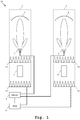
- a first exemplary embodiment of the system 10 according to the first aspect of the invention is illustrated.
- two parallel alignment structures 1, 2 are illustrated herein each comprising a reflector 5, 6 and an antenna 7, 8, for instance a feed antenna, which is arranged at the focal region of the reflector 5, 6.
- the reflectors 5, 6 are situated at the top ends of the alignment structures 1, 2 while the DUTs 3, 4 are placed at the bottom ends so that the reflectors 5, 6 are hanging above the respective DUTs 3, 4.
- the DUTs 3, 4 are wireless devices, for instance modular devices, antenna arrays and the like, preferably operative according to 5G communication standards.
- the alignment structures 1, 2 resemble vertical CATR systems where the CATRs and the DUTs 3, 4 are oriented so that the parallel DUTs 3, 4 do not radiate energy directly towards each other.
- the system further comprises a measuring unit 9, connected to each antenna 7, 8 and performs measurement on the DUTs 3, 4 simultaneously.
- Each of the antennas 7, 8 are connected to the measuring unit 9 via switching means, for instance via radio frequency (RF) switch boxes (not shown), either individually or collectively.
- RF radio frequency
- the measuring unit 9 is able to measure the same performance characteristic (e.g., Error Vector Magnitude) for the DUTs 3, 4.
- the measuring unit 9 is able to measure a plurality of different performance characteristics (e.g., Error Vector Magnitude and Channel Power) for the DUTs 3, 4.
- the measuring unit 9 may additionally include measuring antennas or probes or sensors in order to perform detailed measurement on the DUTs 3, 4.
- the measuring unit 9 comprises signal generating means, data/signal processing means, user interfaces and storage means, which are well-known in the art and are not described in detail to avoid unnecessarily obscuring the invention.
- the system further comprises a positioner 11 connected to the measuring unit 9 and further to the alignment structures 1, 2 in order to synchronize their respective orientation.
- the positioner 11 may optionally connected to the DUTs 3, 4 in order to synchronize their orientation with respect to the alignment structures 1, 2.
- the positioner 11 may orient the alignment structures 1, 2 vertically or horizontally or in a sloping angle with respect to a test plane.
- the positioner 11 may orient the alignment structures 1, 2 at different angles with respect to each other.
- the alignment structures 1, 2 can be oriented externally by the positioner 11, for instance by a user via the measuring unit 9 as per the requirements of production testing.
- the two DUTs 3, 4 to be tested in parallel can be placed on a production line.
- the two alignment structures 1, 2 are vertically oriented above the production line with two DUTs 3, 4 on a conveyor belt or two parallel conveyor belts, which are beneath the respective reflectors 5, 6.
- measurements are performed in parallel with the two corresponding alignment structures 1, 2.
- no shielding enclosure e.g., anechoic chambers
- the alignment structures 1, 2 may comprise some level of shielding 13, 14 and 15, 16 as illustrated herein, for instance to isolate the back-lobes from the antennas 7, 8 and side-lobes of the DUTs 3, 4.
- the antennas 7, 8 illuminate the respective reflectors 5, 6 from the focal region and the DUTs 3, 4 (e.g., antenna arrays) are operative with main radiation power in a solid angle of 120 by 120 degree around the respective reflectors 5, 6. It is to be noted that the example shielding 13, 14 and 15, 16 are partially shown in Fig. 1 . Additional shielding in between the antennas 7, 8 and the respective reflectors 5, 6 may be introduced as required.
- the two alignment structures 1, 2 can be placed, for instance at a close proximity of 1 or 2 meters, preferably less than 2 meters in order to achieve a compact test environment.
- the main radiation from the DUTs 3, 4 is directed in a 120 by 120 solid angle around the reflectors 5, 6 (+/- 60 degrees from boresight in two orthogonal directions)
- the radiation from one DUT will negligibly affect the neighboring DUT in direct line of sight.
- the radiation from DUT 3 will negligibly affect the DUT 4 in direct line of sight.
- the electromagnetic waves radiated by the DUT 3 could actually reach the reflector 6 with non-negligible power.
- the reflector 6 will mostly scatter away from the quiet zone, where the DUT 4 is, the radiation incoming from DUT 3, as DUT 3 is not placed at the focal region of the reflector 6. Consequently, the reflectors 5, 6 and beam collimation mechanisms provide natural interference blocking capabilities from radiation coming from a neighboring test setup.
- a second exemplary embodiment of the system 20 according to the first aspect of the invention is illustrated.
- the system 20 differs from the system 10 of Fig. 1 in that it comprises additional shielding walls 21 or a single shielding wall in between the alignment structures 1, 2 in order to minimize the interferences.
- the shielding walls 21 can be a form of surfaces with metallic skin, segments with RF absorbing materials (e.g., Ferrite tiles or pyramidal foam) or any combination thereof.
- Such shielding walls 21 advantageously suppress the neighboring interferences, particularly in the case when a DUT (e.g., DUT 3) radiates beams with solid angle greater than 120 degrees that would interfere with the neighboring DUT (e.g., DUT 4) as well as with the DUT next to the neighboring DUT 4. Hence, it is possible to test multiple devices on a production line even if one or more devices may radiate waves with main beam solid angle greater than 120 degrees.
- Fig. 3 an exemplary interference situation on a reflector 5 of an alignment structure 1 according to the first aspect of the invention is illustrated.
- the interference source 30 can be, for instance a neighboring DUT. Although the interference source 30 would negligibly affect the DUT 3 in direct line of sight, the interference level on the reflector 5 is at considerable intensity. However, the reflector 5 will almost scatter away the interference from the quiet zone since the interference source 30 is not originating from the focal region of the reflector 5. As a consequence, interferences on the reflector 5 can be adequately minimized even without a shielded enclosure.
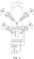
- the interference sources 41, 42 can be the scattering waves from neighboring reflectors and the interference sources 43, 44 can be one or more of the neighboring antennas.
- the interference sources 41, 42, 43, 44 can be any sort of scattering coming from one or more neighboring reflectors, antennas and DUTs.
- most of the interference sources 41, 42, 43, 44 cause interference with a negligible power level and therefore would not affect the antenna 7 as well as the DUT 3 significantly.
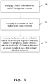
- a shaped reflector 5, 6 is arranged at a top end of the alignment structure 1, 2.
- an antenna 7, 8 is arranged at the focal region of the shaped reflector 5, 6.
- the devices under test 3, 4 are arranged at bottom ends of the plurality of alignment structures 1, 2, opposite to a respective shaped reflector 5, 6.
- the plurality of alignment structures 1, 2 are placed parallel to each other without shielded enclosures.
- the method further comprises the step of measuring a similar performance characteristic for each alignment structures 1, 2. Additionally or alternatively, the method further comprises the step of measuring a different performance characteristic for each alignment structures 1, 2.
- the method further comprises the step of placing the devices under test 3, 4 on a production line, preferably on a conveyor belt at the bottom ends of the plurality of alignment structures 1, 2.
- the method further comprises the step of operating each device under test 3, 4 as a directive antenna with a main beam within a solid angle of 120 degrees.
- the method further comprises the step of performing simultaneous measurements on the devices under test 3, 4 operating with the main beam within the solid angle of 120 degrees.
- the embodiments of the present invention can be implemented by hardware, software, or any combination thereof.
- Various embodiments of the present invention may be implemented by one or more application specific integrated circuits (ASICs), digital signal processors (DSPs), digital signal processing devices (DSPDs), programmable logic devices (PLDs), field programmable gate arrays (FPGAs), processors, controllers, microcontrollers, microprocessors, or the like.
- ASICs application specific integrated circuits
- DSPs digital signal processors
- DSPDs digital signal processing devices
- PLDs programmable logic devices
- FPGAs field programmable gate arrays
- processors controllers, microcontrollers, microprocessors, or the like.
Landscapes
- Physics & Mathematics (AREA)
- General Physics & Mathematics (AREA)
- Electromagnetism (AREA)
- Engineering & Computer Science (AREA)
- Power Engineering (AREA)
- Computer Networks & Wireless Communication (AREA)
- Signal Processing (AREA)
- Variable-Direction Aerials And Aerial Arrays (AREA)
- Aerials With Secondary Devices (AREA)
Abstract
Description
- The invention relates to parallel measurement of devices under test (DUTs) in an open environment, especially for production line testing of multiple DUTs with limited interferences.
- Generally, over the air (OTA) testing is performed in a shielded and encapsulated environment, inside of an anechoic chamber. These chambers are designed to be non-reflective and echo free. The size of the chamber varies with the object and frequency ranges being tested, and it is normally lined with foam pyramids that absorb reflected signals. The testing takes into account the radiation characteristics on the equipment while eliminating interference from any other transmissions. In wireless device production testing, these chambers are required to be opened and closed for subsequent positioning of the device under test (DUT). Alternatively, these chambers are loaded with the DUT using complex mechanisms, for example a six-axis robot. Consequently, the overall time and cost is increased significantly, especially in the case of production testing.
- From the foregoing perspective, an open test environment is beneficial for production testing. However, without the shielding of the chamber, the relative interferences on the test setups certainly degrade the overall test accuracy. Furthermore, in order to test multiple devices (DUTs) simultaneously, especially in an OTA environment, separate anechoic environments are commonly implemented for each DUT for maintaining an acceptable level of interference. For example, the document
US 9,179,340 B2 - Accordingly, the object of the invention is to provide a system and a method for parallel measurement of DUTs for OTA production testing in a simplified and cost-effective manner with minimum level of interference.
- The object is solved by the features of the first independent claim for the system and by the features of the second independent claim for the method. The dependent claims contain further developments.
- According to a first aspect of the invention, a system for parallel measurement of devices under test in an open over the air environment is provided. The system comprises a plurality of alignment structures, each comprising a shaped reflector arranged at a top end of the alignment structure and an antenna arranged at the focal region of the shaped reflector. In this context, the devices under test are arranged at bottom ends of the plurality of alignment structures, opposite to a respective shaped reflector. In addition, the plurality of alignment structures are placed parallel to each other without shielded enclosures.
- Therefore, multiple compact antenna test range (CATR) setups are utilized in order to measure corresponding DUTs without any shielded enclosure. Due to the natural property of CATR, the reflectors will mostly scatter away an incoming interference from the quiet zone, particularly for the radiation from a neighboring DUT. As a consequence, the reflectors and beam collimation mechanisms are providing natural interference blocking capabilities from radiations directing from a neighboring test setup. Advantageously, multiple DUTs can be tested in parallel with limited interferences without the necessity of separate shielded enclosures. This is particularly advantageous for production testing of wireless devices, for instance in fifth generation (5G) production lines.
- According to a first preferred implementation form of said first aspect of the invention, the system further comprises a measuring unit, preferably connected to the antenna of each alignment structures. Advantageously, the parallel measurement of the DUTs is performed in a simplifier manner.
- According to a second preferred implementation form of said first aspect of the invention, the measuring unit is adapted to measure a similar performance characteristic for each alignment structures. Additionally or alternatively, the measuring unit is adapted to measure different performance characteristics for each alignment structures. Hence, a higher measurement flexibility is achieved.
- According to a further preferred implementation form of said first aspect of the invention, the devices under test are placed on a production line, preferably on a conveyor belt at the bottom ends of the plurality of alignment structures. In this context, the DUTs can be placed on a single conveyor belt situated at the bottom ends of the alignment structures. Alternatively, multiple parallel conveyor belts can be arranged at the bottom ends of respective alignment structures.
- According to a further preferred implementation form of said first aspect of the invention, each device under test is operative as a directive antenna with a main beam within a solid angle of 120 degrees. Advantageously, the DUTs are directed with main radiation power in a solid angle of 120 by 120 degrees around the reflector so as to reduce interference towards a neighboring test setup.
- According to a further preferred implementation form of said first aspect of the invention, the measuring unit is adapted to perform measurements simultaneously on the devices under test operating with the main beam within the solid angle of 120 degrees. Advantageously, parallel testing of the DUTs is performed simultaneously.
- According to a further preferred implementation form of said first aspect of the invention, the plurality of alignment structures are arranged horizontally and/or vertically and/or in a sloping position with respect to a test plane. Hence, the system allows flexible test setup with regard to, for instance the type of DUTs to be tested, the alignment requirements for the production line, the arrangement of the test facility and so on.
- According to a further preferred implementation form of said first aspect of the invention, the plurality of alignment structures are arranged in a close proximity, preferably with a separation distance of less than 2 meters. Advantageously, the DUTs are measured in a compact environment.
- According to a further preferred implementation form of said first aspect of the invention, the system further comprises a positioner adapted to synchronize the orientation of the plurality of alignment structures. Hence, the CATRs and the DUTs are advantageously oriented with respect to each other.
- According to a further preferred implementation form of said first aspect of the invention, the system further comprises shielding walls arranged in-between the plurality of alignment structures, and whereby the measuring unit is adapted to perform measurements simultaneously on the devices under test operating with the main beam with solid angle greater than 120 degrees. Advantageously, the DUTs can be measured with limited interferences even if the DUTs are not perfectly oriented and/or beamforming.
- According to a second aspect of the invention, a method is provided for parallel measurement of devices under test in an open over the air environment in a system comprising a plurality of alignment structures. The method comprises the step of arranging a shaped reflector at a top end of the alignment structure. In addition, the method comprises the step of arranging an antenna at the focal region of the shaped reflector. Moreover, the method comprises the step of arranging the devices under test at bottom ends of the plurality of alignment structures, opposite to a respective shaped reflector. In this context, the plurality of alignment structures are placed parallel to each other without shielded enclosures. Therefore, multiple compact antenna test range (CATR) setups are utilized in order to measure corresponding DUTs without any shielded enclosure.
- According to a first preferred implementation form of said second aspect of the invention, the method further comprises the step of measuring a similar performance characteristic for each alignment structures. In addition to this or as an alternative, the method further comprises the step of measuring different performance characteristics for each alignment structures. Advantageously, a higher measurement flexibility is realized.
- According to a second preferred implementation form of said second aspect of the invention, the method further comprises the step of placing the devices under test on a production line, preferably on a conveyor belt at the bottom ends of the plurality of alignment structures. In this context, the DUTs can be placed on a single conveyor belt situated at the bottom ends of the alignment structures. Alternatively, multiple parallel conveyor belts can be arranged at the bottom ends of respective alignment structures.
- According to a further preferred implementation form of said second aspect of the invention, the method further comprises the step of operating each device under test as a directive antenna with a main beam within a solid angle of 120 degrees. Advantageously, the DUTs are directed with main radiation power in a solid angle of 120 by 120 degrees around the reflector so as to reduce interference towards a neighboring test setup.
- According to a further preferred implementation form of said second aspect of the invention, the method further comprises the step of performing simultaneous measurements on the devices under test operating with the main beam within the solid angle of 120 degrees. Advantageously, parallel testing of the DUTs is performed simultaneously.
- Exemplary embodiments of the invention are now further explained with respect to the drawings by way of example only, and not for limitation. In the drawings:
- Fig. 1
- shows a first exemplary embodiment of the system according to the first aspect of the invention;
- Fig. 2
- shows a second exemplary embodiment of the system according to the first aspect of the invention;
- Fig. 3
- shows an exemplary interference situation on a reflector of an alignment structure according to the first aspect of the invention;
- Fig. 4
- shows an exemplary interference situation on the antennas of an alignment structure according to the first aspect of the invention; and
- Fig. 5
- shows an exemplary embodiment of the method according to the second aspect of the invention.
- Reference will now be made in detail to the embodiments of the present invention, examples of which are illustrated in the accompanying drawings. However, the following embodiments of the present invention may be variously modified and the range of the present invention is not limited by the following embodiments.
- In
Fig. 1 , a first exemplary embodiment of thesystem 10 according to the first aspect of the invention is illustrated. In particular, twoparallel alignment structures reflector antenna reflector reflectors alignment structures DUTs reflectors respective DUTs DUTs alignment structures DUTs parallel DUTs - The system further comprises a measuring
unit 9, connected to eachantenna DUTs antennas unit 9 via switching means, for instance via radio frequency (RF) switch boxes (not shown), either individually or collectively. Hence, the measuringunit 9 is able to measure the same performance characteristic (e.g., Error Vector Magnitude) for theDUTs unit 9 is able to measure a plurality of different performance characteristics (e.g., Error Vector Magnitude and Channel Power) for theDUTs unit 9 may additionally include measuring antennas or probes or sensors in order to perform detailed measurement on theDUTs unit 9 comprises signal generating means, data/signal processing means, user interfaces and storage means, which are well-known in the art and are not described in detail to avoid unnecessarily obscuring the invention. - The system further comprises a
positioner 11 connected to the measuringunit 9 and further to thealignment structures positioner 11 may optionally connected to theDUTs alignment structures positioner 11 may orient thealignment structures positioner 11 may orient thealignment structures alignment structures positioner 11, for instance by a user via the measuringunit 9 as per the requirements of production testing. - Particularly for the
alignment structures DUTs alignment structures DUTs respective reflectors DUTs corresponding alignment structures alignment structures antennas DUTs antennas respective reflectors DUTs 3, 4 (e.g., antenna arrays) are operative with main radiation power in a solid angle of 120 by 120 degree around therespective reflectors Fig. 1 . Additional shielding in between theantennas respective reflectors - The two
alignment structures DUTs reflectors 5, 6 (+/- 60 degrees from boresight in two orthogonal directions), the radiation from one DUT will negligibly affect the neighboring DUT in direct line of sight. For instance, the radiation fromDUT 3 will negligibly affect theDUT 4 in direct line of sight. On the other hand, the electromagnetic waves radiated by theDUT 3 could actually reach thereflector 6 with non-negligible power. However, thereflector 6 will mostly scatter away from the quiet zone, where theDUT 4 is, the radiation incoming fromDUT 3, asDUT 3 is not placed at the focal region of thereflector 6. Consequently, thereflectors - It is important to note that the number of alignment structures as well as the number of DUTs and their respective orientation are illustrated herein by way of example only, and not for limitation.
- In
Fig. 2 , a second exemplary embodiment of thesystem 20 according to the first aspect of the invention is illustrated. Thesystem 20 differs from thesystem 10 ofFig. 1 in that it comprisesadditional shielding walls 21 or a single shielding wall in between thealignment structures walls 21 can be a form of surfaces with metallic skin, segments with RF absorbing materials (e.g., Ferrite tiles or pyramidal foam) or any combination thereof. Such shieldingwalls 21 advantageously suppress the neighboring interferences, particularly in the case when a DUT (e.g., DUT 3) radiates beams with solid angle greater than 120 degrees that would interfere with the neighboring DUT (e.g., DUT 4) as well as with the DUT next to the neighboringDUT 4. Hence, it is possible to test multiple devices on a production line even if one or more devices may radiate waves with main beam solid angle greater than 120 degrees. - In
Fig. 3 , an exemplary interference situation on areflector 5 of analignment structure 1 according to the first aspect of the invention is illustrated. Theinterference source 30 can be, for instance a neighboring DUT. Although theinterference source 30 would negligibly affect theDUT 3 in direct line of sight, the interference level on thereflector 5 is at considerable intensity. However, thereflector 5 will almost scatter away the interference from the quiet zone since theinterference source 30 is not originating from the focal region of thereflector 5. As a consequence, interferences on thereflector 5 can be adequately minimized even without a shielded enclosure. - In
Fig. 4 , an exemplary interference situation on theantennas alignment structure 1 according to the first aspect of the invention is illustrated. The interference sources 41, 42 can be the scattering waves from neighboring reflectors and theinterference sources interference sources interference sources antenna 7 as well as theDUT 3 significantly. - In
Fig. 5 , an exemplary embodiment of the method according to the second aspect of the invention is illustrated. In afirst step 100, a shapedreflector alignment structure second step 101, anantenna reflector third step 102, the devices undertest alignment structures reflector alignment structures - Moreover, the method further comprises the step of measuring a similar performance characteristic for each
alignment structures alignment structures - It is particularly advantageous if the method further comprises the step of placing the devices under
test alignment structures - In addition, the method further comprises the step of operating each device under
test - Moreover, the method further comprises the step of performing simultaneous measurements on the devices under
test - The embodiments of the present invention can be implemented by hardware, software, or any combination thereof. Various embodiments of the present invention may be implemented by one or more application specific integrated circuits (ASICs), digital signal processors (DSPs), digital signal processing devices (DSPDs), programmable logic devices (PLDs), field programmable gate arrays (FPGAs), processors, controllers, microcontrollers, microprocessors, or the like.
- While various embodiments of the present invention have been described above, it should be understood that they have been presented by way of example only, and not limitation. Numerous changes to the disclosed embodiments can be made in accordance with the disclosure herein without departing from the spirit or scope of the invention. Thus, the breadth and scope of the present invention should not be limited by any of the above described embodiments. Rather, the scope of the invention should be defined in accordance with the following claims and their equivalents.
- Although the invention has been illustrated and described with respect to one or more implementations, equivalent alterations and modifications will occur to others skilled in the art upon the reading and understanding of this specification and the annexed drawings. In addition, while a particular feature of the invention may have been disclosed with respect to only one of several implementations, such feature may be combined with one or more other features of the other implementations as may be desired and advantageous for any given or particular application.
Claims (15)
- A system (10) for parallel measurement of devices under test (3,4) in an open over the air environment comprises a plurality of alignment structures (1,2), each comprising:a shaped reflector (5,6) arranged at a top end of the alignment structure (1,2), andan antenna (7,8) arranged at the focal region of the shaped reflector (5, 6) ;wherein the devices under test (3,4) are arranged at bottom ends of the plurality of alignment structures (1,2), opposite to a respective shaped reflector (5,6), and wherein the plurality of alignment structures (1,2) are placed parallel to each other without shielded enclosures.
- The system according to claim 1,
wherein the system (10) further comprises a measuring unit (9), preferably connected to the antenna (7,8) of each alignment structures (1,2). - The system according to claim 2,
wherein the measuring unit (9) is adapted to measure a similar performance characteristic for each alignment structures (1,2), and/or
wherein the measuring unit (9) is adapted to measure different performance characteristics for each alignment structures (1,2). - The system according to any of claims 1 to 3,
wherein the devices under test (3,4) are placed on a production line, preferably on a conveyor belt at the bottom ends of the plurality of alignment structures (1,2). - The system according to any of claims 1 to 4,
wherein each device under test (3,4) is operative as a directive antenna with a main beam within a solid angle of 120 degrees. - The system according to claim 5,
wherein the measuring unit (9) is adapted to perform measurements simultaneously on the devices under test (3,4) operating with the main beam within the solid angle of 120 degrees. - The system according to any of claims 1 to 6,
wherein the plurality of alignment structures (1,2) are arranged horizontally with respect to a test plane, and/or wherein the plurality of alignment structures (1,2) are arranged vertically with respect to the test plane, and/or wherein the plurality of alignment structures (1,2) are arranged in a sloping position with respect to the test plane. - The system according to any of claims 1 to 7,
wherein the plurality of alignment structures (1,2) are arranged in a close proximity, preferably with a separation distance of less than 2 meters. - The system according to any of claims 1 to 8,
wherein the system (10) further comprises a positioner (11) adapted to synchronize the orientation of the plurality of alignment structures (1,2). - The system according to any of claims 1 to 9,
wherein the system (10) further comprises shielding walls (21) arranged in-between the plurality of alignment structures (1,2), and whereby the measuring unit (9) is adapted to perform measurements simultaneously on the devices under test (3,4) operating with the main beam with solid angle greater than 120 degrees. - A method for parallel measurement of devices under test (3,4) in an open over the air environment in a system (10) comprising a plurality of alignment structures (1,2) comprises the steps of:arranging (100) a shaped reflector (5,6) at a top end of the alignment structure (1,2),arranging (101) an antenna (7,8) at the focal region of the shaped reflector (5,6),arranging (102) the devices under test (3,4) at bottom ends of the plurality of alignment structures (1,2), opposite to a respective shaped reflector (5,6), and wherein the plurality of alignment structures (1,2) are placed parallel to each other without shielded enclosures.
- The method according to claim 11,
wherein the method further comprises the step of measuring a similar performance characteristic for each alignment structures (1,2), and/or
wherein the method further comprises the step of measuring different performance characteristics for each alignment structures (1,2). - The method according to claim 11 or 12,
wherein the method further comprises the step of placing the devices under test (3,4) on a production line, preferably on a conveyor belt at the bottom ends of the plurality of alignment structures (1,2). - The method according to any of claims 11 to 13,
wherein the method further comprises the step of operating each device under test (3,4) as a directive antenna with a main beam within a solid angle of 120 degrees. - The method according to claim 14,
wherein the method further comprises the step of performing simultaneous measurements on the devices under test (3,4) operating with the main beam within the solid angle of 120 degrees.
Priority Applications (3)
| Application Number | Priority Date | Filing Date | Title |
|---|---|---|---|
| EP19197656.2A EP3796008B1 (en) | 2019-09-17 | 2019-09-17 | System and method for parallel measurement of devices under test in an open over the air environment |
| CN201911165322.0A CN112526223B (en) | 2019-09-17 | 2019-11-25 | System and method for parallel measurement of devices under test in an open air environment |
| US16/694,672 US11137424B2 (en) | 2019-09-17 | 2019-11-25 | System and method for parallel measurement of devices under test in an open over the air environment |
Applications Claiming Priority (1)
| Application Number | Priority Date | Filing Date | Title |
|---|---|---|---|
| EP19197656.2A EP3796008B1 (en) | 2019-09-17 | 2019-09-17 | System and method for parallel measurement of devices under test in an open over the air environment |
Publications (2)
| Publication Number | Publication Date |
|---|---|
| EP3796008A1 true EP3796008A1 (en) | 2021-03-24 |
| EP3796008B1 EP3796008B1 (en) | 2023-07-26 |
Family
ID=67988884
Family Applications (1)
| Application Number | Title | Priority Date | Filing Date |
|---|---|---|---|
| EP19197656.2A Active EP3796008B1 (en) | 2019-09-17 | 2019-09-17 | System and method for parallel measurement of devices under test in an open over the air environment |
Country Status (3)
| Country | Link |
|---|---|
| US (1) | US11137424B2 (en) |
| EP (1) | EP3796008B1 (en) |
| CN (1) | CN112526223B (en) |
Families Citing this family (1)
| Publication number | Priority date | Publication date | Assignee | Title |
|---|---|---|---|---|
| EP4427067B1 (en) * | 2021-11-19 | 2026-03-04 | Airspan Networks Inc. | Over-the-air product verification test using antenna and reflector arrays |
Citations (5)
| Publication number | Priority date | Publication date | Assignee | Title |
|---|---|---|---|---|
| US20100109932A1 (en) * | 2008-10-24 | 2010-05-06 | Kefeng Liu | Termination of edges of a parabolic reflector in a compact range |
| US9179340B2 (en) | 2006-06-07 | 2015-11-03 | Ets-Lindgren, Lp | Systems and methods for over-the-air testing of wireless systems |
| US20180340968A1 (en) * | 2017-05-26 | 2018-11-29 | Rohde & Schwarz Gmbh & Co. Kg | Over the air measurement system and method |
| US20190101579A1 (en) * | 2017-09-29 | 2019-04-04 | Rohde & Schwarz Gmbh & Co. Kg | Measurement system and method for performing test measurements |
| US20190215085A1 (en) * | 2018-01-11 | 2019-07-11 | Rohde & Schwarz Gmbh & Co. Kg | Test system and test method |
Family Cites Families (16)
| Publication number | Priority date | Publication date | Assignee | Title |
|---|---|---|---|---|
| US8412112B2 (en) * | 2009-05-06 | 2013-04-02 | Ets-Lindgren, L.P. | Systems and methods for simulating a multipath radio frequency environment |
| EP2721424B1 (en) * | 2011-06-15 | 2019-07-24 | Bluetest AB | Improved method and apparatus for measuring the performance of antennas, mobile phones and other wireless terminals |
| CN105264390B (en) * | 2013-06-07 | 2018-02-23 | 莱特普茵特公司 | Systems and methods for testing radio frequency wireless signal transceivers using wireless test signals |
| CN104569635B (en) * | 2013-10-15 | 2018-06-08 | 深圳市通用测试系统有限公司 | Wireless terminal antenna performance test system |
| JP6496133B2 (en) * | 2014-12-02 | 2019-04-03 | アンリツ株式会社 | Wireless terminal measuring apparatus and wireless terminal measuring method |
| CN106291145B (en) * | 2015-05-12 | 2019-03-01 | 深圳市通用测试系统有限公司 | Wireless Terminal Test System |
| US20160359718A1 (en) * | 2015-06-05 | 2016-12-08 | Litepoint Corporation | Method for calibrating an over-the-air (ota) test system for testing multiple radio frequency (rf) data packet signal transceivers |
| CN106559149B (en) * | 2015-09-25 | 2019-07-12 | 中国移动通信集团公司 | A kind of throughput testing approach and device of multiple terminals |
| EP3182619B1 (en) * | 2015-12-16 | 2020-12-23 | RanLOS AB | Method and apparatus for testing wireless communication to vehicles |
| CN109791171B (en) * | 2016-09-30 | 2021-08-17 | 瑞典爱立信有限公司 | Reduced mesh for total radiated power measurement |
| US10333631B2 (en) * | 2017-08-24 | 2019-06-25 | Rohde & Schwarz Gmbh & Co. Kg | Test arrangement and test method |
| US10309999B2 (en) * | 2017-10-06 | 2019-06-04 | The Boeing Company | Compact test range system with adjustable feed horn locations |
| US10809296B2 (en) * | 2017-11-28 | 2020-10-20 | Rohde & Schwarz Gmbh & Co. Kg | Over-the-air test system and method for testing a device under test |
| EP3546958B1 (en) * | 2018-03-28 | 2022-11-23 | Rohde & Schwarz GmbH & Co. KG | Measurement system and method for testing a device under test |
| CN109100639A (en) * | 2018-09-13 | 2018-12-28 | 苏州永安丰新能源科技有限公司 | A kind of OTA test device and method for communication device context adaptive testing |
| CN110568413A (en) * | 2019-09-10 | 2019-12-13 | 广东恒沃技术有限公司 | test system and method integrating radar calibration, active transceiving and measurement parameters |
-
2019
- 2019-09-17 EP EP19197656.2A patent/EP3796008B1/en active Active
- 2019-11-25 CN CN201911165322.0A patent/CN112526223B/en active Active
- 2019-11-25 US US16/694,672 patent/US11137424B2/en active Active
Patent Citations (5)
| Publication number | Priority date | Publication date | Assignee | Title |
|---|---|---|---|---|
| US9179340B2 (en) | 2006-06-07 | 2015-11-03 | Ets-Lindgren, Lp | Systems and methods for over-the-air testing of wireless systems |
| US20100109932A1 (en) * | 2008-10-24 | 2010-05-06 | Kefeng Liu | Termination of edges of a parabolic reflector in a compact range |
| US20180340968A1 (en) * | 2017-05-26 | 2018-11-29 | Rohde & Schwarz Gmbh & Co. Kg | Over the air measurement system and method |
| US20190101579A1 (en) * | 2017-09-29 | 2019-04-04 | Rohde & Schwarz Gmbh & Co. Kg | Measurement system and method for performing test measurements |
| US20190215085A1 (en) * | 2018-01-11 | 2019-07-11 | Rohde & Schwarz Gmbh & Co. Kg | Test system and test method |
Also Published As
| Publication number | Publication date |
|---|---|
| CN112526223B (en) | 2025-07-15 |
| US20210080490A1 (en) | 2021-03-18 |
| CN112526223A (en) | 2021-03-19 |
| US11137424B2 (en) | 2021-10-05 |
| EP3796008B1 (en) | 2023-07-26 |
Similar Documents
| Publication | Publication Date | Title |
|---|---|---|
| US11397205B2 (en) | Measurement system and method of performing an over-the-air test | |
| CN112154331B (en) | Aerial testing of millimeter wave integrated circuits with integrated antennas | |
| CN112425002B (en) | Near field antenna for remote radio control of antenna arrays | |
| US10686540B2 (en) | Anechoic test chamber, test system and test method for testing the antennas of a device under test | |
| US20170242061A1 (en) | Test apparatus and a method of testing of an antenna | |
| EP3699611B1 (en) | Measurement system, measurement setup as well as method for performing measurements | |
| US10746775B1 (en) | Testing system and method with multiple antennas | |
| WO2022051374A1 (en) | Method and system for over-the-air testing of millimeter wave antenna arrays | |
| US10536228B2 (en) | Test system and test method | |
| US11137424B2 (en) | System and method for parallel measurement of devices under test in an open over the air environment | |
| Orta et al. | Performance degradation of dielectric radome covered antennas | |
| US11340278B2 (en) | Measurement system for testing a device under test over-the-air | |
| CN115134008B (en) | Comprehensive integrated test system and method for OTA test | |
| US12407426B2 (en) | Probes for device testing | |
| CN115993490A (en) | Aerial Measurement System | |
| Fordham | An introduction to antenna test ranges, measurements and instrumentation | |
| CN115993487B (en) | Aerial Measurement System | |
| TWM639827U (en) | Separate Test Equipment | |
| US10062964B2 (en) | Shield box for wireless terminal test | |
| KR20120071840A (en) | Apparatus and method for testing antenna in wireless communication system | |
| RU2027194C1 (en) | Device for measuring parameters of aerials | |
| Parveg et al. | Calibration procedure for 2-D MIMO over-the-air multi-probe test system | |
| Yemini et al. | Compact RCS Test Range Feed Carousel and Baffle House Design | |
| CN120834871A (en) | Aerial measurement system and method | |
| EP4573376A1 (en) | Calibration and testing apparatus for radio-frequency devices |
Legal Events
| Date | Code | Title | Description |
|---|---|---|---|
| PUAI | Public reference made under article 153(3) epc to a published international application that has entered the european phase |
Free format text: ORIGINAL CODE: 0009012 |
|
| STAA | Information on the status of an ep patent application or granted ep patent |
Free format text: STATUS: THE APPLICATION HAS BEEN PUBLISHED |
|
| AK | Designated contracting states |
Kind code of ref document: A1 Designated state(s): AL AT BE BG CH CY CZ DE DK EE ES FI FR GB GR HR HU IE IS IT LI LT LU LV MC MK MT NL NO PL PT RO RS SE SI SK SM TR |
|
| AX | Request for extension of the european patent |
Extension state: BA ME |
|
| STAA | Information on the status of an ep patent application or granted ep patent |
Free format text: STATUS: REQUEST FOR EXAMINATION WAS MADE |
|
| 17P | Request for examination filed |
Effective date: 20210407 |
|
| RBV | Designated contracting states (corrected) |
Designated state(s): AL AT BE BG CH CY CZ DE DK EE ES FI FR GB GR HR HU IE IS IT LI LT LU LV MC MK MT NL NO PL PT RO RS SE SI SK SM TR |
|
| GRAP | Despatch of communication of intention to grant a patent |
Free format text: ORIGINAL CODE: EPIDOSNIGR1 |
|
| STAA | Information on the status of an ep patent application or granted ep patent |
Free format text: STATUS: GRANT OF PATENT IS INTENDED |
|
| GRAS | Grant fee paid |
Free format text: ORIGINAL CODE: EPIDOSNIGR3 |
|
| INTG | Intention to grant announced |
Effective date: 20230322 |
|
| GRAA | (expected) grant |
Free format text: ORIGINAL CODE: 0009210 |
|
| STAA | Information on the status of an ep patent application or granted ep patent |
Free format text: STATUS: THE PATENT HAS BEEN GRANTED |
|
| P01 | Opt-out of the competence of the unified patent court (upc) registered |
Effective date: 20230525 |
|
| AK | Designated contracting states |
Kind code of ref document: B1 Designated state(s): AL AT BE BG CH CY CZ DE DK EE ES FI FR GB GR HR HU IE IS IT LI LT LU LV MC MK MT NL NO PL PT RO RS SE SI SK SM TR |
|
| REG | Reference to a national code |
Ref country code: CH Ref legal event code: EP |
|
| REG | Reference to a national code |
Ref country code: CH Ref legal event code: PL |
|
| REG | Reference to a national code |
Ref country code: IE Ref legal event code: FG4D |
|
| REG | Reference to a national code |
Ref country code: DE Ref legal event code: R096 Ref document number: 602019033412 Country of ref document: DE |
|
| RBV | Designated contracting states (corrected) |
Designated state(s): AL AT BE BG CY CZ DE DK EE ES FI FR GB GR HR HU IS IT LT LU LV MC MK MT NL NO PL PT RO RS SE SI SK SM TR |
|
| REG | Reference to a national code |
Ref country code: LT Ref legal event code: MG9D |
|
| REG | Reference to a national code |
Ref country code: NL Ref legal event code: MP Effective date: 20230726 |
|
| REG | Reference to a national code |
Ref country code: AT Ref legal event code: MK05 Ref document number: 1592517 Country of ref document: AT Kind code of ref document: T Effective date: 20230726 |
|
| PG25 | Lapsed in a contracting state [announced via postgrant information from national office to epo] |
Ref country code: NL Free format text: LAPSE BECAUSE OF FAILURE TO SUBMIT A TRANSLATION OF THE DESCRIPTION OR TO PAY THE FEE WITHIN THE PRESCRIBED TIME-LIMIT Effective date: 20230726 |
|
| PG25 | Lapsed in a contracting state [announced via postgrant information from national office to epo] |
Ref country code: GR Free format text: LAPSE BECAUSE OF FAILURE TO SUBMIT A TRANSLATION OF THE DESCRIPTION OR TO PAY THE FEE WITHIN THE PRESCRIBED TIME-LIMIT Effective date: 20231027 |
|
| PG25 | Lapsed in a contracting state [announced via postgrant information from national office to epo] |
Ref country code: IS Free format text: LAPSE BECAUSE OF FAILURE TO SUBMIT A TRANSLATION OF THE DESCRIPTION OR TO PAY THE FEE WITHIN THE PRESCRIBED TIME-LIMIT Effective date: 20231126 |
|
| PG25 | Lapsed in a contracting state [announced via postgrant information from national office to epo] |
Ref country code: SE Free format text: LAPSE BECAUSE OF FAILURE TO SUBMIT A TRANSLATION OF THE DESCRIPTION OR TO PAY THE FEE WITHIN THE PRESCRIBED TIME-LIMIT Effective date: 20230726 Ref country code: RS Free format text: LAPSE BECAUSE OF FAILURE TO SUBMIT A TRANSLATION OF THE DESCRIPTION OR TO PAY THE FEE WITHIN THE PRESCRIBED TIME-LIMIT Effective date: 20230726 Ref country code: PT Free format text: LAPSE BECAUSE OF FAILURE TO SUBMIT A TRANSLATION OF THE DESCRIPTION OR TO PAY THE FEE WITHIN THE PRESCRIBED TIME-LIMIT Effective date: 20231127 Ref country code: NO Free format text: LAPSE BECAUSE OF FAILURE TO SUBMIT A TRANSLATION OF THE DESCRIPTION OR TO PAY THE FEE WITHIN THE PRESCRIBED TIME-LIMIT Effective date: 20231026 Ref country code: LV Free format text: LAPSE BECAUSE OF FAILURE TO SUBMIT A TRANSLATION OF THE DESCRIPTION OR TO PAY THE FEE WITHIN THE PRESCRIBED TIME-LIMIT Effective date: 20230726 Ref country code: LT Free format text: LAPSE BECAUSE OF FAILURE TO SUBMIT A TRANSLATION OF THE DESCRIPTION OR TO PAY THE FEE WITHIN THE PRESCRIBED TIME-LIMIT Effective date: 20230726 Ref country code: IS Free format text: LAPSE BECAUSE OF FAILURE TO SUBMIT A TRANSLATION OF THE DESCRIPTION OR TO PAY THE FEE WITHIN THE PRESCRIBED TIME-LIMIT Effective date: 20231126 Ref country code: HR Free format text: LAPSE BECAUSE OF FAILURE TO SUBMIT A TRANSLATION OF THE DESCRIPTION OR TO PAY THE FEE WITHIN THE PRESCRIBED TIME-LIMIT Effective date: 20230726 Ref country code: GR Free format text: LAPSE BECAUSE OF FAILURE TO SUBMIT A TRANSLATION OF THE DESCRIPTION OR TO PAY THE FEE WITHIN THE PRESCRIBED TIME-LIMIT Effective date: 20231027 Ref country code: FI Free format text: LAPSE BECAUSE OF FAILURE TO SUBMIT A TRANSLATION OF THE DESCRIPTION OR TO PAY THE FEE WITHIN THE PRESCRIBED TIME-LIMIT Effective date: 20230726 Ref country code: AT Free format text: LAPSE BECAUSE OF FAILURE TO SUBMIT A TRANSLATION OF THE DESCRIPTION OR TO PAY THE FEE WITHIN THE PRESCRIBED TIME-LIMIT Effective date: 20230726 |
|
| PG25 | Lapsed in a contracting state [announced via postgrant information from national office to epo] |
Ref country code: PL Free format text: LAPSE BECAUSE OF FAILURE TO SUBMIT A TRANSLATION OF THE DESCRIPTION OR TO PAY THE FEE WITHIN THE PRESCRIBED TIME-LIMIT Effective date: 20230726 |
|
| PG25 | Lapsed in a contracting state [announced via postgrant information from national office to epo] |
Ref country code: ES Free format text: LAPSE BECAUSE OF FAILURE TO SUBMIT A TRANSLATION OF THE DESCRIPTION OR TO PAY THE FEE WITHIN THE PRESCRIBED TIME-LIMIT Effective date: 20230726 |
|
| REG | Reference to a national code |
Ref country code: DE Ref legal event code: R097 Ref document number: 602019033412 Country of ref document: DE |
|
| PG25 | Lapsed in a contracting state [announced via postgrant information from national office to epo] |
Ref country code: SM Free format text: LAPSE BECAUSE OF FAILURE TO SUBMIT A TRANSLATION OF THE DESCRIPTION OR TO PAY THE FEE WITHIN THE PRESCRIBED TIME-LIMIT Effective date: 20230726 Ref country code: RO Free format text: LAPSE BECAUSE OF FAILURE TO SUBMIT A TRANSLATION OF THE DESCRIPTION OR TO PAY THE FEE WITHIN THE PRESCRIBED TIME-LIMIT Effective date: 20230726 Ref country code: ES Free format text: LAPSE BECAUSE OF FAILURE TO SUBMIT A TRANSLATION OF THE DESCRIPTION OR TO PAY THE FEE WITHIN THE PRESCRIBED TIME-LIMIT Effective date: 20230726 Ref country code: EE Free format text: LAPSE BECAUSE OF FAILURE TO SUBMIT A TRANSLATION OF THE DESCRIPTION OR TO PAY THE FEE WITHIN THE PRESCRIBED TIME-LIMIT Effective date: 20230726 Ref country code: DK Free format text: LAPSE BECAUSE OF FAILURE TO SUBMIT A TRANSLATION OF THE DESCRIPTION OR TO PAY THE FEE WITHIN THE PRESCRIBED TIME-LIMIT Effective date: 20230726 Ref country code: CZ Free format text: LAPSE BECAUSE OF FAILURE TO SUBMIT A TRANSLATION OF THE DESCRIPTION OR TO PAY THE FEE WITHIN THE PRESCRIBED TIME-LIMIT Effective date: 20230726 Ref country code: SK Free format text: LAPSE BECAUSE OF FAILURE TO SUBMIT A TRANSLATION OF THE DESCRIPTION OR TO PAY THE FEE WITHIN THE PRESCRIBED TIME-LIMIT Effective date: 20230726 |
|
| PG25 | Lapsed in a contracting state [announced via postgrant information from national office to epo] |
Ref country code: LU Free format text: LAPSE BECAUSE OF NON-PAYMENT OF DUE FEES Effective date: 20230917 |
|
| REG | Reference to a national code |
Ref country code: BE Ref legal event code: MM Effective date: 20230930 |
|
| PG25 | Lapsed in a contracting state [announced via postgrant information from national office to epo] |
Ref country code: LU Free format text: LAPSE BECAUSE OF NON-PAYMENT OF DUE FEES Effective date: 20230917 Ref country code: IT Free format text: LAPSE BECAUSE OF FAILURE TO SUBMIT A TRANSLATION OF THE DESCRIPTION OR TO PAY THE FEE WITHIN THE PRESCRIBED TIME-LIMIT Effective date: 20230726 Ref country code: MC Free format text: LAPSE BECAUSE OF FAILURE TO SUBMIT A TRANSLATION OF THE DESCRIPTION OR TO PAY THE FEE WITHIN THE PRESCRIBED TIME-LIMIT Effective date: 20230726 |
|
| PLBE | No opposition filed within time limit |
Free format text: ORIGINAL CODE: 0009261 |
|
| STAA | Information on the status of an ep patent application or granted ep patent |
Free format text: STATUS: NO OPPOSITION FILED WITHIN TIME LIMIT |
|
| 26N | No opposition filed |
Effective date: 20240429 |
|
| PG25 | Lapsed in a contracting state [announced via postgrant information from national office to epo] |
Ref country code: SI Free format text: LAPSE BECAUSE OF FAILURE TO SUBMIT A TRANSLATION OF THE DESCRIPTION OR TO PAY THE FEE WITHIN THE PRESCRIBED TIME-LIMIT Effective date: 20230726 |
|
| PG25 | Lapsed in a contracting state [announced via postgrant information from national office to epo] |
Ref country code: BE Free format text: LAPSE BECAUSE OF NON-PAYMENT OF DUE FEES Effective date: 20230930 |
|
| PG25 | Lapsed in a contracting state [announced via postgrant information from national office to epo] |
Ref country code: BG Free format text: LAPSE BECAUSE OF FAILURE TO SUBMIT A TRANSLATION OF THE DESCRIPTION OR TO PAY THE FEE WITHIN THE PRESCRIBED TIME-LIMIT Effective date: 20230726 |
|
| PG25 | Lapsed in a contracting state [announced via postgrant information from national office to epo] |
Ref country code: BG Free format text: LAPSE BECAUSE OF FAILURE TO SUBMIT A TRANSLATION OF THE DESCRIPTION OR TO PAY THE FEE WITHIN THE PRESCRIBED TIME-LIMIT Effective date: 20230726 |
|
| PG25 | Lapsed in a contracting state [announced via postgrant information from national office to epo] |
Ref country code: CY Free format text: LAPSE BECAUSE OF FAILURE TO SUBMIT A TRANSLATION OF THE DESCRIPTION OR TO PAY THE FEE WITHIN THE PRESCRIBED TIME-LIMIT; INVALID AB INITIO Effective date: 20190917 |
|
| PG25 | Lapsed in a contracting state [announced via postgrant information from national office to epo] |
Ref country code: HU Free format text: LAPSE BECAUSE OF FAILURE TO SUBMIT A TRANSLATION OF THE DESCRIPTION OR TO PAY THE FEE WITHIN THE PRESCRIBED TIME-LIMIT; INVALID AB INITIO Effective date: 20190917 |
|
| PGFP | Annual fee paid to national office [announced via postgrant information from national office to epo] |
Ref country code: DE Payment date: 20250919 Year of fee payment: 7 |
|
| PGFP | Annual fee paid to national office [announced via postgrant information from national office to epo] |
Ref country code: GB Payment date: 20250923 Year of fee payment: 7 |
|
| PGFP | Annual fee paid to national office [announced via postgrant information from national office to epo] |
Ref country code: FR Payment date: 20250925 Year of fee payment: 7 |
|
| PG25 | Lapsed in a contracting state [announced via postgrant information from national office to epo] |
Ref country code: TR Free format text: LAPSE BECAUSE OF FAILURE TO SUBMIT A TRANSLATION OF THE DESCRIPTION OR TO PAY THE FEE WITHIN THE PRESCRIBED TIME-LIMIT Effective date: 20230726 |