EP3795967A1 - Aircraft temperature sensor - Google Patents
Aircraft temperature sensor Download PDFInfo
- Publication number
- EP3795967A1 EP3795967A1 EP19212854.4A EP19212854A EP3795967A1 EP 3795967 A1 EP3795967 A1 EP 3795967A1 EP 19212854 A EP19212854 A EP 19212854A EP 3795967 A1 EP3795967 A1 EP 3795967A1
- Authority
- EP
- European Patent Office
- Prior art keywords
- thermistor
- optical fiber
- sensor
- sheath
- conductor
- Prior art date
- Legal status (The legal status is an assumption and is not a legal conclusion. Google has not performed a legal analysis and makes no representation as to the accuracy of the status listed.)
- Granted
Links
Images


Classifications
-
- G—PHYSICS
- G01—MEASURING; TESTING
- G01K—MEASURING TEMPERATURE; MEASURING QUANTITY OF HEAT; THERMALLY-SENSITIVE ELEMENTS NOT OTHERWISE PROVIDED FOR
- G01K7/00—Measuring temperature based on the use of electric or magnetic elements directly sensitive to heat ; Power supply therefor, e.g. using thermoelectric elements
- G01K7/16—Measuring temperature based on the use of electric or magnetic elements directly sensitive to heat ; Power supply therefor, e.g. using thermoelectric elements using resistive elements
- G01K7/22—Measuring temperature based on the use of electric or magnetic elements directly sensitive to heat ; Power supply therefor, e.g. using thermoelectric elements using resistive elements the element being a non-linear resistance, e.g. thermistor
- G01K7/223—Measuring temperature based on the use of electric or magnetic elements directly sensitive to heat ; Power supply therefor, e.g. using thermoelectric elements using resistive elements the element being a non-linear resistance, e.g. thermistor characterised by the shape of the resistive element
-
- G—PHYSICS
- G01—MEASURING; TESTING
- G01K—MEASURING TEMPERATURE; MEASURING QUANTITY OF HEAT; THERMALLY-SENSITIVE ELEMENTS NOT OTHERWISE PROVIDED FOR
- G01K11/00—Measuring temperature based upon physical or chemical changes not covered by groups G01K3/00, G01K5/00, G01K7/00 or G01K9/00
- G01K11/32—Measuring temperature based upon physical or chemical changes not covered by groups G01K3/00, G01K5/00, G01K7/00 or G01K9/00 using changes in transmittance, scattering or luminescence in optical fibres
-
- G—PHYSICS
- G01—MEASURING; TESTING
- G01K—MEASURING TEMPERATURE; MEASURING QUANTITY OF HEAT; THERMALLY-SENSITIVE ELEMENTS NOT OTHERWISE PROVIDED FOR
- G01K7/00—Measuring temperature based on the use of electric or magnetic elements directly sensitive to heat ; Power supply therefor, e.g. using thermoelectric elements
- G01K7/02—Measuring temperature based on the use of electric or magnetic elements directly sensitive to heat ; Power supply therefor, e.g. using thermoelectric elements using thermoelectric elements, e.g. thermocouples
- G01K7/04—Measuring temperature based on the use of electric or magnetic elements directly sensitive to heat ; Power supply therefor, e.g. using thermoelectric elements using thermoelectric elements, e.g. thermocouples the object to be measured not forming one of the thermoelectric materials
- G01K7/06—Measuring temperature based on the use of electric or magnetic elements directly sensitive to heat ; Power supply therefor, e.g. using thermoelectric elements using thermoelectric elements, e.g. thermocouples the object to be measured not forming one of the thermoelectric materials the thermoelectric materials being arranged one within the other with the junction at one end exposed to the object, e.g. sheathed type
-
- G—PHYSICS
- G01—MEASURING; TESTING
- G01K—MEASURING TEMPERATURE; MEASURING QUANTITY OF HEAT; THERMALLY-SENSITIVE ELEMENTS NOT OTHERWISE PROVIDED FOR
- G01K7/00—Measuring temperature based on the use of electric or magnetic elements directly sensitive to heat ; Power supply therefor, e.g. using thermoelectric elements
- G01K7/16—Measuring temperature based on the use of electric or magnetic elements directly sensitive to heat ; Power supply therefor, e.g. using thermoelectric elements using resistive elements
- G01K7/22—Measuring temperature based on the use of electric or magnetic elements directly sensitive to heat ; Power supply therefor, e.g. using thermoelectric elements using resistive elements the element being a non-linear resistance, e.g. thermistor
-
- G—PHYSICS
- G01—MEASURING; TESTING
- G01K—MEASURING TEMPERATURE; MEASURING QUANTITY OF HEAT; THERMALLY-SENSITIVE ELEMENTS NOT OTHERWISE PROVIDED FOR
- G01K7/00—Measuring temperature based on the use of electric or magnetic elements directly sensitive to heat ; Power supply therefor, e.g. using thermoelectric elements
- G01K7/40—Measuring temperature based on the use of electric or magnetic elements directly sensitive to heat ; Power supply therefor, e.g. using thermoelectric elements using ionisation of gases
Definitions
- the sensor comprises a temperature sensor elongated with respect to an axis.
- the temperature sensor comprises a sheath elongated with respect to the axis.
- the temperature sensor comprises a central conductor disposed within the sheath and elongated with respect to the axis having a conductor material defining a conductor temperature coefficient having a conductor coefficient magnitude.
- the temperature sensor comprises an optical fiber disposed within the sheath.
- the temperature sensor comprises a thermistor disposed within the sheath and surrounding the central conductor, the thermistor having thermistor material defining a thermistor temperature coefficient defining a thermistor coefficient magnitude greater than the conductor coefficient magnitude.
- optical fiber is disposed in an atmosphere of noble gas and the atmosphere of noble gas is retained by the trough and the sheath.
- the extrusion machine 300 comprises a body 302.
- the extrusion machine 300 further comprises a die 304 having a key 306.
- the die 304 may be rotated or oriented to adjust an angle of the key 306 with respect to an elongate axis of the thermistor 110, 210.
- the key 306 may be configured to generate the trough 114.
Landscapes
- Physics & Mathematics (AREA)
- General Physics & Mathematics (AREA)
- Nonlinear Science (AREA)
- Measuring Temperature Or Quantity Of Heat (AREA)
- Geophysics And Detection Of Objects (AREA)
- Glass Compositions (AREA)
- Measuring Fluid Pressure (AREA)
Abstract
Description
- The present disclosure relates to the art of aircraft temperature detection systems. Aircraft temperature detection systems comprise sensors and sensory devices to determine overheat situations and other temperature anomalies.
- Temperature detection systems may be configured to cooperate with controllers and other electronic or logical devices that provide annunciation or indication to operators.
- Disclosed is a sensor for detecting temperature of an aircraft. The sensor comprises a temperature sensor elongated with respect to an axis. The temperature sensor comprises a sheath elongated with respect to the axis. The temperature sensor comprises a central conductor disposed within the sheath and elongated with respect to the axis having a conductor material defining a conductor temperature coefficient having a conductor coefficient magnitude. The temperature sensor comprises an optical fiber disposed within the sheath. The temperature sensor comprises a thermistor disposed within the sheath and surrounding the central conductor, the thermistor having thermistor material defining a thermistor temperature coefficient defining a thermistor coefficient magnitude greater than the conductor coefficient magnitude.
- In addition to one or more of the features described above, or as an alternative, further embodiments may include that the optical fiber forms a helix with respect to the axis.
- In addition to one or more of the features described above, or as an alternative, further embodiments may include that the helix defines a tangent vector having a constant angle respective the axis.
- In addition to one or more of the features described above, or as an alternative, further embodiments may include that the thermistor defines a trough sized to retain the optical fiber formed to coincide with the helix.
- In addition to one or more of the features described above, or as an alternative, further embodiments may include that the trough is sized to retain the optical fiber and to have contact with the optical fiber at only two contact points.
- In addition to one or more of the features described above, or as an alternative, further embodiments may include that the optical fiber is disposed in an atmosphere of noble gas and the atmosphere of noble gas is retained by the trough and the sheath.
- Also disclosed is a sensor for detecting temperature of an aircraft. The sensor comprises a temperature sensor elongated with respect to an axis and having a cross-section respective the axis. The cross-section comprises a sheath. The cross-section comprises a central conductor disposed within the sheath having a conductor material defining a conductor temperature coefficient having a conductor coefficient magnitude. The cross-section comprises an optical fiber disposed within the sheath. The cross-section comprises a thermistor disposed within the sheath and surrounding the central conductor, the thermistor having thermistor material defining a thermistor temperature coefficient defining a thermistor coefficient magnitude greater than the conductor coefficient magnitude.
- In addition to one or more of the features described above, or as an alternative, further embodiments may include that the thermistor defines a trough sized to retain the optical fiber, and the optical fiber is disposed within the trough.
- In addition to one or more of the features described above, or as an alternative, further embodiments may include that the trough is defined to extend parallel to the axis forming a helix about the axis and the optical fiber traverses the axis within the trough.
- In addition to one or more of the features described above, or as an alternative, further embodiments may include that the helix defines a tangent vector having a constant angle with respect to the axis.
- In addition to one or more of the features described above, or as an alternative, further embodiments may include that the trough is sized to retain the optical fiber and contact the optical fiber at only two contact points.
- In addition to one or more of the features described above, or as an alternative, further embodiments may include that the optical fiber is disposed in an atmosphere of noble gas and the atmosphere of noble gas is retained by the trough and the sheath.
- In addition to one or more of the features described above, or as an alternative, further embodiments may include that the central conductor defines a tube sized to retain the optical fiber, and the optical fiber is disposed within the tube.
- In addition to one or more of the features described above, or as an alternative, further embodiments may include that the tube sized to retain the optical fiber circumscribes the optical fiber.
- In addition to one or more of the features described above, or as an alternative, further embodiments may include that the optical fiber is disposed in an atmosphere of noble gas retained by the tube.
- In addition to one or more of the features described above, or as an alternative, further embodiments may include that the sheath is filled by the thermistor and the optical fiber is encapsulated by the thermistor and the sheath.
- In addition to one or more of the features described above, or as an alternative, further embodiments may include that the central conductor and the thermistor form the sensor with the sheath and the sheath defines a ground.
- Also disclosed is a method of manufacturing a sensor. The method comprises combining a central conductor with a thermistor by extruding the thermistor with the central conductor through a die. The method comprises combining an optical fiber with the central conductor and the thermistor. The method comprises sheathing the optical fiber, the thermistor, and the central conductor to form the sensor.
- In addition to one or more of the features described above, or as an alternative, further embodiments may include that the die comprises a key configured to define a trough in the thermistor and combining the optical fiber with the central conductor and the thermistor comprises inserting the optical fiber in the trough.
- In addition to one or more of the features described above, or as an alternative, further embodiments may include rotating the die during the combining of the central conductor and the thermistor such that the trough forms a helix with respect to an axis of the sensor.
- The following descriptions should not be considered limiting in any way. With reference to the accompanying drawings, like elements are numbered alike:
-
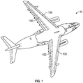
FIG. 1 illustrates an example an aircraft having a temperature sensor; -
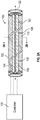
FIG. 2A illustrates an example of one implementation of the teachings in this disclosure on a temperature sensor of an aircraft; -
FIG. 2B illustrates a cross-section of the temperature sensor ofFIG. 2A ; -
FIG. 3A illustrates an example of another implementation of the teachings in this disclosure on a temperature sensor of an aircraft; -
FIG. 3B illustrates a cross-section of the temperature sensor ofFIG. 3A ; -
FIG. 4 illustrates an extrusion machine having a die; and -
FIG. 5 illustrates a method of manufacturing a temperature sensor of an aircraft. - A detailed description of one or more embodiments of the disclosed apparatus and method are presented herein by way of exemplification and not limitation with reference to the Figures.
- Referring to
FIG. 1 anaircraft 10 is shown. Theaircraft 10 may comprisetemperature sensors 100. As an example, thetemperature sensors 100 may be disposed throughout theaircraft 10. Thetemperature sensors 100 may be disposed on wings of theaircraft 10. - Referring to
FIGs. 2A-2B , atemperature sensor 100 according to one or more implementations of the present disclosure is shown. Thetemperature sensor 100 comprisessheath 102. Thesheath 102 may be made of any material. Thesheath 102 may comprise Inconel. Thesheath 102 may be made of a metal or a metal alloy that provide flame or heat protection. Thesheath 102 may be elongated with respect toaxis 122. Thesheath 102 may serve as an electrical ground path. Theaxis 122 may define a particular portion or portions of thesensor 100. Thesensor 100 may be elongated to cover anentire aircraft 10, aircraft wings, or portions thereof. Non-limiting, specific examples comprise engine nacelles, auxiliary power unit bays, and landing gear bays. - As illustrated, the
sheath 102 houses acentral conductor 104. Thecentral conductor 104 is alongaxis 122 inFIG. 2 . Thecentral conductor 104 may be solid, stranded, tubed, or any other implement. Thecentral conductor 104 may be located at any radial position with respect to theaxis 122. Theaxis 122 may pass through the center of thesheath 102 or thecentral conductor 104. Theaxis 122 may be offset from the center of thesheath 102 or thecentral conductor 104. Thecentral conductor 104 may be made of any conductive material (e.g., copper). The conductive material defines a conductor temperature coefficient. The conductor temperature coefficient defines a relative change of a resistance or conductance as temperature changes. The conductor temperature coefficient may be positive or negative. As shown in Equation 1, the temperature coefficient k corresponds to relative changes in resistance, R, and temperature, t.
- The conductor temperature coefficient k may comprise a sign (e.g., positive or negative) and a conductor coefficient magnitude. The conductor coefficient magnitude may be defined numerically or in other ways.
- The
sensor 100 also comprises aground conductor 106. Theground conductor 106 may be made of the same or various materials than thecentral conductor 104. Theground conductor 106 may be connected with thesheath 102 and external ground points through groundinglegs 108. The groundinglegs 108 may have the same material properties as theground conductor 106 or thecentral conductor 104. It should be appreciated that theground conductor 106 may be omitted and substituted for a direct connection with thesheath 102. - A
thermistor 110 is be disposed within thesheath 102. Thethermistor 110 may be composed of any type of temperature-dependent resistive material or combination thereof. Thethermistor 110 may fill thesheath 102. Thethermistor 110 may loosely fit thesheath 102 such thatatmosphere 116 fills, naturally or through disposition, between thethermistor 110 and thesheath 102. Theatmosphere 116 may be an inert or noble gas. Thethermistor 110 may be extruded through a die 304 (as shown in one of many examples inFIG. 4 ) and shrink wrapped or similarly extruded with thesheath 102. Thethermistor 110 may surround, circumscribe, join, or encapsulate thecentral conductor 104, or any combination thereof. - An
optical fiber 112 is to be disposed within thesheath 102. Those versed in the art will readily appreciate that the optical fiber may be comprise other components or combinations. As a non-limiting example, theoptical fiber 112 may be a fiber optic cable. Theoptical fiber 112 may comprise a jacket material. The optical fiber may be silica based with disposed coatings. Theoptical fiber 112 may be disposed to translate across, among, along, or about theaxis 122. Theoptical fiber 112 may be formed in a helix with respect to theaxis 122. Theoptical fiber 112 has a tangent 140 with respect to theaxis 122 that may have aconstant angle 142. Theoptical fiber 112 may comprise fiber Bragg gratings (FBG) configured to provide changes in light transmission or reflection along theoptical fiber 112 that correspond with changes in temperature. As such, the changes allow acontroller 130 or another implement to sense temperature changes at particular locations along thesensor 100. Theoptical fiber 112 may be situated without encumbrance or strain to ensure proper reading from the FBG. Thethermistor 110 defines atrough 114 to guide theoptical fiber 112. Thetrough 114 may be sized to touch theoptical fiber 112 without encumbrance. That is, thetrough 114 may be sized to have not more than twocontact points optical fiber 112. As such, theoptical fiber 112 is unencumbered by surroundings, increasing the measurement accuracy provided by the FBG. - The
sensor 100 encloses two sensing loops. One sensing loop is formed by theoptical fiber 112, and the other sensing loop is formed by thecentral conductor 104, thethermistor 110, and a ground, which may be either theground conductor 106 or thesheath 102. Thecontroller 130 receives these inputs, as shown, and operates or informs operators of theaircraft 10 as such. As an example, if thecontroller 130 determines that temperatures associated with thesensor 100 are greater than a predetermined threshold, thecontroller 130 alerts an operator of the condition. Thesensor 100 may be configured to indicate the location of the temperature fluctuation based on the FBGs or other implementations along thesensor 100. Automatic implementations may comprise temperature reduction measures or other aircraft operations. - The
controller 130 may comprise two thresholds. A low temperature threshold (∼500 °C) and a high temperature threshold (∼800 °C). The high temperature threshold may allow thecontroller 130 or operators to actuate halon systems in theaircraft 10. Theoptical fiber 112 may provide the lower temperature threshold and continuous temperature monitoring. Thecentral conductor 104,thermistor 110, andsheath 102 may cover both thresholds. Those versed in the art will readily appreciate that different combinations may be used to satisfy the thresholds. In some circumstances, thethermistor 110 may create a tradeoff between low and high temperature thresholds and their associated response times to temperature changes. The addition of theoptical fiber 112 can offset this trade off. Theoptical fiber 112 is able to detect lower thresholds and continuously monitor temperature. High temperature material limitations of theoptical fiber 112 and FBGs theoptical fiber 112 may not survive the high temperature events and may be sacrificial during such events. - Referring to
FIGs. 3A-3B , asensor 200 is shown in accordance with one or more implementations of the current disclosure. Thesensor 200 comprises asheath 202. Thesheath 202 is elongated along theaxis 222. Thesheath 202 houses acentral conductor 204. Thecentral conductor 204 may be a tube or hollow cylinder. Thecentral conductor 204 may be associated with thethermistor 210. Thecentral conductor 204 may be disposed within thesheath 202 and surrounded, circumscribed, joined, encapsulated or any combination thereof by thethermistor 210. Thecentral conductor 204 may be aligned with theaxis 222 and elongated along theaxis 222. Thecentral conductor 204 may be offset from theaxis 222. Thecentral conductor 204 may house anoptical fiber 212. Theoptical fiber 212 may be elongated with respect to theaxis 222. Theoptical fiber 212 may be disposed in anatmosphere 216 of inert or noble gas. Theatmosphere 216 may be naturally or intentionally disposed. - The
sensor 200 encloses two sensing loops. One sensing loop is formed by theoptical fiber 212, which may be single-ended operating according to refraction or reflection, and the other sensing loop is formed by thecentral conductor 204, thethermistor 210, and a ground, which may be thesheath 102. Thecontroller 130 receives these inputs, as shown, and operates or informs operators of theaircraft 10 as such. - The
sensors controllers controllers controllers controllers - Referring to
FIG. 4 , anextrusion machine 300 is shown. Theextrusion machine 300 comprises abody 302. Theextrusion machine 300 further comprises adie 304 having a key 306. Thedie 304 may be rotated or oriented to adjust an angle of the key 306 with respect to an elongate axis of thethermistor trough 114. - Referring to
FIG. 5 , amethod 400 is shown in accordance with one or more implementations of the present disclosure. Themethod 400 illustrates a step-by-step process for manufacturing asensor FIG. 5 may be rearranged, omitted, or repeated. Further, the steps may be performed in parallel or in sequence. - The
method 400 comprises combining acentral conductor thermistor thermistor central conductor die 304 instep 402. Thecentral conductor extrusion machine 300 during extrusion of thethermistor - The
method 400 may comprise rotating the die 304 while combining thecentral conductor thermistor trough 114 with the helix form as shown, as one of many examples, inFIG. 2A . - The
method 400 comprises combining anoptical fiber central conductor thermistor optical fiber optical fiber central conductor thermistor optical fiber 112 may be inserted into thetrough 114. Themethod 400 comprises sheathing theoptical fiber thermistor central conductor sensor sheath thermistor thermistor sheath atmosphere thermistor sheath method 400 may comprise injectedatmosphere sheath sensor - It should be appreciated that any type of connecting apparatus between the
sensor controllers optical fiber sensors controllers sheath - The terminology used herein is for the purpose of describing the features associated with the present disclosure and is not intended to be limiting of the present disclosure. As used herein, the singular forms "a", "an" and "the" are intended to comprise the plural forms as well, unless the context clearly indicates otherwise. It will be further understood that the terms "comprises" and/or "comprising," when used in this specification, specify the presence of stated features, integers, steps, operations, elements, and/or components, but do not preclude the presence or addition of one or more other features, integers, steps, operations, element components, and/or groups thereof.
- While the present disclosure has been described with reference to features and parts, it will be understood by those skilled in the art that various changes may be made, and equivalents may be substituted for elements thereof without departing from the scope of the present disclosure. In addition, many modifications may be made to adapt a particular situation or material to the teachings of the present disclosure without departing from the essential scope thereof. Therefore, it is intended that the present disclosure not be limited to any particular features or parts disclosed as the best mode contemplated for carrying out this present disclosure, but that the present disclosure will comprise all that falls within the scope of the claims.
Claims (15)
- A sensor for detecting temperature of an aircraft, the sensor comprising:
a temperature sensor elongated with respect to an axis comprising:a sheath elongated with respect to the axis;a central conductor disposed within the sheath and elongated with respect to the axis having a conductor material defining a conductor temperature coefficient having a conductor coefficient magnitude;an optical fiber disposed within the sheath; anda thermistor disposed within the sheath and surrounding the central conductor, the thermistor having thermistor material defining a thermistor temperature coefficient defining a thermistor coefficient magnitude greater than the conductor coefficient magnitude. - The sensor of claim 1, wherein the optical fiber forms a helix with respect to the axis;
optionally wherein the helix defines a tangent vector having a constant angle respective the axis. - The sensor of claim 2, wherein the thermistor defines a trough sized to retain the optical fiber formed to coincide with the helix.
- A sensor for detecting temperature of an aircraft, the sensor comprising:
a temperature sensor elongated with respect to an axis and having a cross-section respective the axis, the cross-section comprising:a sheath;a central conductor disposed within the sheath having a conductor material defining a conductor temperature coefficient having a conductor coefficient magnitude;an optical fiber disposed within the sheath; anda thermistor disposed within the sheath and surrounding the central conductor, the thermistor having thermistor material defining a thermistor temperature coefficient defining a thermistor coefficient magnitude greater than the conductor coefficient magnitude. - The sensor of claim 4, wherein the thermistor defines a trough sized to retain the optical fiber, and the optical fiber is disposed within the trough.
- The sensor of claim 5, wherein the trough is defined to extend parallel to the axis forming a helix about the axis and the optical fiber traverses the axis within the trough;
optionally, wherein the helix defines a tangent vector having a constant angle with respect to the axis. - The sensor of claim 3, 5 or 6, wherein the trough is sized to retain the optical fiber and contact the optical fiber at only two contact points.
- The sensor of claim 3, 5, 6 or 7, wherein the optical fiber is disposed in an atmosphere of noble gas and the atmosphere of noble gas is retained by the trough and the sheath.
- The sensor of claim 1 or 4, wherein the central conductor defines a tube sized to retain the optical fiber, and the optical fiber is disposed within the tube;
optionally wherein the tube sized to retain the optical fiber circumscribes the optical fiber. - The sensor of claim 9, wherein the optical fiber is disposed in an atmosphere of noble gas retained by the tube.
- The sensor of any preceding claim, wherein the sheath is filled by the thermistor and the optical fiber is encapsulated by the thermistor and the sheath.
- The sensor of any preceding claim, wherein the central conductor and the thermistor form the sensor with the sheath and the sheath defines a ground.
- A method of manufacturing a sensor comprising:combining a central conductor with a thermistor by extruding the thermistor with the central conductor through a die;combining an optical fiber with the central conductor and the thermistor; andsheathing the optical fiber, the thermistor, and the central conductor to form the sensor.
- The method of claim 13, wherein the die comprises a key configured to define a trough in the thermistor and combining the optical fiber with the central conductor and the thermistor comprises inserting the optical fiber in the trough.
- The method of claim 14, further comprising rotating the die during the combining of the central conductor and the thermistor such that the trough forms a helix with respect to an axis of the sensor.
Applications Claiming Priority (1)
| Application Number | Priority Date | Filing Date | Title |
|---|---|---|---|
| US16/579,155 US10871403B1 (en) | 2019-09-23 | 2019-09-23 | Aircraft temperature sensor |
Publications (2)
| Publication Number | Publication Date |
|---|---|
| EP3795967A1 true EP3795967A1 (en) | 2021-03-24 |
| EP3795967B1 EP3795967B1 (en) | 2023-04-05 |
Family
ID=68762590
Family Applications (1)
| Application Number | Title | Priority Date | Filing Date |
|---|---|---|---|
| EP19212854.4A Active EP3795967B1 (en) | 2019-09-23 | 2019-12-02 | Aircraft temperature sensor |
Country Status (3)
| Country | Link |
|---|---|
| US (1) | US10871403B1 (en) |
| EP (1) | EP3795967B1 (en) |
| ES (1) | ES2942458T3 (en) |
Families Citing this family (2)
| Publication number | Priority date | Publication date | Assignee | Title |
|---|---|---|---|---|
| US11237067B2 (en) * | 2019-08-20 | 2022-02-01 | Kidde Technologies, Inc. | Uncertainty diagnosis for temperature detection systems |
| US12196820B2 (en) * | 2022-04-02 | 2025-01-14 | Pratt & Whitney Canada Corp. | Detecting damage to electric conductor using electromagnetic radiation |
Citations (3)
| Publication number | Priority date | Publication date | Assignee | Title |
|---|---|---|---|---|
| GB2276944A (en) * | 1993-04-05 | 1994-10-12 | Central Research Lab Ltd | Excess-temperature detection arrangement |
| EP1455320A1 (en) * | 2003-03-03 | 2004-09-08 | Cerberus S.A.S. | Fire or overheating detection system |
| EP3246683A1 (en) * | 2016-05-19 | 2017-11-22 | Kidde Technologies, Inc. | Optical health monitoring for aircraft overheat and fire detection systems |
Family Cites Families (20)
| Publication number | Priority date | Publication date | Assignee | Title |
|---|---|---|---|---|
| US4654520A (en) * | 1981-08-24 | 1987-03-31 | Griffiths Richard W | Structural monitoring system using fiber optics |
| US4668857A (en) * | 1985-08-16 | 1987-05-26 | Belton Corporation | Temperature self-regulating resistive heating element |
| US5064271A (en) | 1989-03-14 | 1991-11-12 | Santa Barbara Research Center | Fiber optic flame and overheat sensing system with self test |
| US5051595A (en) | 1989-12-06 | 1991-09-24 | Santa Barbara Research Center | Fiber optic flame detection and temperature measurement system employing doped optical fiber |
| US5051590A (en) | 1989-12-06 | 1991-09-24 | Santa Barbara Research Center | Fiber optic flame detection and temperature measurement system having one or more in-line temperature dependent optical filters |
| EP0553675A1 (en) | 1992-01-29 | 1993-08-04 | Siemens Aktiengesellschaft | Method and device for control of the temperature of a turbine component |
| WO1993018494A1 (en) | 1992-03-11 | 1993-09-16 | The Boeing Company | Thermal condition sensor system for monitoring equipment operation |
| US5841617A (en) * | 1997-04-07 | 1998-11-24 | Bpw, Inc. | Electrical safety device with conductive polymer sensor |
| DE19736276B4 (en) | 1997-08-21 | 2006-07-27 | Alstom Technology Ltd | Optical pyrometer for gas turbines |
| US6559437B1 (en) * | 2000-09-20 | 2003-05-06 | Ralph E. Pope, Jr. | Fiber optic damage sensor for wire and cable |
| DE10111640A1 (en) | 2001-03-10 | 2002-10-02 | Airbus Gmbh | Procedure for the detection and reporting of overheating and fires in an aircraft |
| US6724195B2 (en) * | 2002-03-29 | 2004-04-20 | Jerome R. Lurtz | Contact sensor |
| US8306373B2 (en) | 2009-05-15 | 2012-11-06 | General Electric Company | Fiber Bragg grating sensing package and system for gas turbine temperature measurement |
| US8248260B1 (en) * | 2009-07-20 | 2012-08-21 | Pope Ralph E | Electrical safety device for temperature control and mechanical damage |
| US9787083B2 (en) * | 2012-12-06 | 2017-10-10 | Twin-Star International, Inc. | Overheat-resistant power cord and method |
| GB2511803B (en) | 2013-03-14 | 2015-07-29 | Kidde Tech Inc | Pneumatic sensing apparatus |
| US10002508B2 (en) | 2016-02-10 | 2018-06-19 | Kidde Technologies, Inc. | Pneumatic fire detectors |
| US10658833B2 (en) * | 2016-03-23 | 2020-05-19 | Solaredge Technologies Ltd. | Conductor temperature detector |
| CA2967988C (en) | 2016-05-19 | 2024-01-09 | Kidde Technologies, Inc. | Optical health monitoring for aircraft overheat and fire detection systems |
| US10151643B2 (en) | 2016-08-22 | 2018-12-11 | The Boeing Company | Thermal event indicator for aircraft engine |
-
2019
- 2019-09-23 US US16/579,155 patent/US10871403B1/en active Active
- 2019-12-02 ES ES19212854T patent/ES2942458T3/en active Active
- 2019-12-02 EP EP19212854.4A patent/EP3795967B1/en active Active
Patent Citations (3)
| Publication number | Priority date | Publication date | Assignee | Title |
|---|---|---|---|---|
| GB2276944A (en) * | 1993-04-05 | 1994-10-12 | Central Research Lab Ltd | Excess-temperature detection arrangement |
| EP1455320A1 (en) * | 2003-03-03 | 2004-09-08 | Cerberus S.A.S. | Fire or overheating detection system |
| EP3246683A1 (en) * | 2016-05-19 | 2017-11-22 | Kidde Technologies, Inc. | Optical health monitoring for aircraft overheat and fire detection systems |
Also Published As
| Publication number | Publication date |
|---|---|
| EP3795967B1 (en) | 2023-04-05 |
| US10871403B1 (en) | 2020-12-22 |
| ES2942458T3 (en) | 2023-06-01 |
Similar Documents
| Publication | Publication Date | Title |
|---|---|---|
| EP3795967B1 (en) | Aircraft temperature sensor | |
| US9513111B2 (en) | Self-tensed and fully spring jacketed optical fiber sensing structure | |
| AU2016380886B2 (en) | Downhole cable with reduced diameter | |
| US6559437B1 (en) | Fiber optic damage sensor for wire and cable | |
| US20120125596A1 (en) | Ruggedized fiber optic cable and method of optical fiber transmission | |
| US10910831B2 (en) | Monitoring system to monitor the condition of an industrial wiring system and corresponding industrial wiring system | |
| CN100373745C (en) | Apparatus and method for analysis of power transmission line condition | |
| NZ538181A (en) | Apparatus and method for evaluating underground electric power cables | |
| EP3301462A1 (en) | A monitoring and alert system for industrial cables | |
| CN105140728A (en) | A cable joint and a cable joint temperature measuring system | |
| EP2873117B1 (en) | Gapping measurement sensor for hv connector | |
| US9188495B2 (en) | Strain sensing cable | |
| JPH0593656A (en) | Temperature sensor and its preparation | |
| US7302844B2 (en) | Measurement element for determining a flow rate | |
| CN107086071B (en) | Monitoring cable | |
| EP3524950B1 (en) | Temperature monitoring apparatus | |
| US3798760A (en) | Method of making resistance wire temperature sensor | |
| US20230194357A1 (en) | Temperature probe and method for manufacturing a temperature probe | |
| CN112326058A (en) | A system and method for sensing temperature | |
| EP0647951A2 (en) | Electrical cables | |
| US3761857A (en) | Resistance wire temperature sensor and method of making same | |
| JP2005283148A (en) | Power cable conductor temperature estimation method | |
| US7365631B2 (en) | Overheat detection sensor | |
| CN113272916A (en) | Self-powered in-core detector device for measuring flux in a nuclear reactor core | |
| GB2077471A (en) | Cable for use in a security system |
Legal Events
| Date | Code | Title | Description |
|---|---|---|---|
| PUAI | Public reference made under article 153(3) epc to a published international application that has entered the european phase |
Free format text: ORIGINAL CODE: 0009012 |
|
| STAA | Information on the status of an ep patent application or granted ep patent |
Free format text: STATUS: THE APPLICATION HAS BEEN PUBLISHED |
|
| AK | Designated contracting states |
Kind code of ref document: A1 Designated state(s): AL AT BE BG CH CY CZ DE DK EE ES FI FR GB GR HR HU IE IS IT LI LT LU LV MC MK MT NL NO PL PT RO RS SE SI SK SM TR |
|
| AX | Request for extension of the european patent |
Extension state: BA ME |
|
| STAA | Information on the status of an ep patent application or granted ep patent |
Free format text: STATUS: REQUEST FOR EXAMINATION WAS MADE |
|
| 17P | Request for examination filed |
Effective date: 20210922 |
|
| RBV | Designated contracting states (corrected) |
Designated state(s): AL AT BE BG CH CY CZ DE DK EE ES FI FR GB GR HR HU IE IS IT LI LT LU LV MC MK MT NL NO PL PT RO RS SE SI SK SM TR |
|
| RIN1 | Information on inventor provided before grant (corrected) |
Inventor name: CORETH, STEFAN Inventor name: SIMPSON, TERRY |
|
| GRAP | Despatch of communication of intention to grant a patent |
Free format text: ORIGINAL CODE: EPIDOSNIGR1 |
|
| STAA | Information on the status of an ep patent application or granted ep patent |
Free format text: STATUS: GRANT OF PATENT IS INTENDED |
|
| RIC1 | Information provided on ipc code assigned before grant |
Ipc: G01K 11/32 20210101ALI20220913BHEP Ipc: G01K 7/22 20060101AFI20220913BHEP |
|
| INTG | Intention to grant announced |
Effective date: 20221017 |
|
| GRAS | Grant fee paid |
Free format text: ORIGINAL CODE: EPIDOSNIGR3 |
|
| GRAA | (expected) grant |
Free format text: ORIGINAL CODE: 0009210 |
|
| STAA | Information on the status of an ep patent application or granted ep patent |
Free format text: STATUS: THE PATENT HAS BEEN GRANTED |
|
| AK | Designated contracting states |
Kind code of ref document: B1 Designated state(s): AL AT BE BG CH CY CZ DE DK EE ES FI FR GB GR HR HU IE IS IT LI LT LU LV MC MK MT NL NO PL PT RO RS SE SI SK SM TR |
|
| REG | Reference to a national code |
Ref country code: GB Ref legal event code: FG4D |
|
| REG | Reference to a national code |
Ref country code: CH Ref legal event code: EP |
|
| REG | Reference to a national code |
Ref country code: AT Ref legal event code: REF Ref document number: 1558561 Country of ref document: AT Kind code of ref document: T Effective date: 20230415 |
|
| REG | Reference to a national code |
Ref country code: DE Ref legal event code: R096 Ref document number: 602019027140 Country of ref document: DE |
|
| REG | Reference to a national code |
Ref country code: IE Ref legal event code: FG4D |
|
| REG | Reference to a national code |
Ref country code: ES Ref legal event code: FG2A Ref document number: 2942458 Country of ref document: ES Kind code of ref document: T3 Effective date: 20230601 |
|
| P01 | Opt-out of the competence of the unified patent court (upc) registered |
Effective date: 20230603 |
|
| REG | Reference to a national code |
Ref country code: LT Ref legal event code: MG9D |
|
| REG | Reference to a national code |
Ref country code: NL Ref legal event code: MP Effective date: 20230405 |
|
| REG | Reference to a national code |
Ref country code: AT Ref legal event code: MK05 Ref document number: 1558561 Country of ref document: AT Kind code of ref document: T Effective date: 20230405 |
|
| PG25 | Lapsed in a contracting state [announced via postgrant information from national office to epo] |
Ref country code: NL Free format text: LAPSE BECAUSE OF FAILURE TO SUBMIT A TRANSLATION OF THE DESCRIPTION OR TO PAY THE FEE WITHIN THE PRESCRIBED TIME-LIMIT Effective date: 20230405 |
|
| PG25 | Lapsed in a contracting state [announced via postgrant information from national office to epo] |
Ref country code: SE Free format text: LAPSE BECAUSE OF FAILURE TO SUBMIT A TRANSLATION OF THE DESCRIPTION OR TO PAY THE FEE WITHIN THE PRESCRIBED TIME-LIMIT Effective date: 20230405 Ref country code: PT Free format text: LAPSE BECAUSE OF FAILURE TO SUBMIT A TRANSLATION OF THE DESCRIPTION OR TO PAY THE FEE WITHIN THE PRESCRIBED TIME-LIMIT Effective date: 20230807 Ref country code: NO Free format text: LAPSE BECAUSE OF FAILURE TO SUBMIT A TRANSLATION OF THE DESCRIPTION OR TO PAY THE FEE WITHIN THE PRESCRIBED TIME-LIMIT Effective date: 20230705 Ref country code: AT Free format text: LAPSE BECAUSE OF FAILURE TO SUBMIT A TRANSLATION OF THE DESCRIPTION OR TO PAY THE FEE WITHIN THE PRESCRIBED TIME-LIMIT Effective date: 20230405 |
|
| PG25 | Lapsed in a contracting state [announced via postgrant information from national office to epo] |
Ref country code: RS Free format text: LAPSE BECAUSE OF FAILURE TO SUBMIT A TRANSLATION OF THE DESCRIPTION OR TO PAY THE FEE WITHIN THE PRESCRIBED TIME-LIMIT Effective date: 20230405 Ref country code: PL Free format text: LAPSE BECAUSE OF FAILURE TO SUBMIT A TRANSLATION OF THE DESCRIPTION OR TO PAY THE FEE WITHIN THE PRESCRIBED TIME-LIMIT Effective date: 20230405 Ref country code: LV Free format text: LAPSE BECAUSE OF FAILURE TO SUBMIT A TRANSLATION OF THE DESCRIPTION OR TO PAY THE FEE WITHIN THE PRESCRIBED TIME-LIMIT Effective date: 20230405 Ref country code: LT Free format text: LAPSE BECAUSE OF FAILURE TO SUBMIT A TRANSLATION OF THE DESCRIPTION OR TO PAY THE FEE WITHIN THE PRESCRIBED TIME-LIMIT Effective date: 20230405 Ref country code: IS Free format text: LAPSE BECAUSE OF FAILURE TO SUBMIT A TRANSLATION OF THE DESCRIPTION OR TO PAY THE FEE WITHIN THE PRESCRIBED TIME-LIMIT Effective date: 20230805 Ref country code: HR Free format text: LAPSE BECAUSE OF FAILURE TO SUBMIT A TRANSLATION OF THE DESCRIPTION OR TO PAY THE FEE WITHIN THE PRESCRIBED TIME-LIMIT Effective date: 20230405 Ref country code: GR Free format text: LAPSE BECAUSE OF FAILURE TO SUBMIT A TRANSLATION OF THE DESCRIPTION OR TO PAY THE FEE WITHIN THE PRESCRIBED TIME-LIMIT Effective date: 20230706 Ref country code: AL Free format text: LAPSE BECAUSE OF FAILURE TO SUBMIT A TRANSLATION OF THE DESCRIPTION OR TO PAY THE FEE WITHIN THE PRESCRIBED TIME-LIMIT Effective date: 20230405 |
|
| PG25 | Lapsed in a contracting state [announced via postgrant information from national office to epo] |
Ref country code: FI Free format text: LAPSE BECAUSE OF FAILURE TO SUBMIT A TRANSLATION OF THE DESCRIPTION OR TO PAY THE FEE WITHIN THE PRESCRIBED TIME-LIMIT Effective date: 20230405 |
|
| REG | Reference to a national code |
Ref country code: DE Ref legal event code: R097 Ref document number: 602019027140 Country of ref document: DE |
|
| PG25 | Lapsed in a contracting state [announced via postgrant information from national office to epo] |
Ref country code: SK Free format text: LAPSE BECAUSE OF FAILURE TO SUBMIT A TRANSLATION OF THE DESCRIPTION OR TO PAY THE FEE WITHIN THE PRESCRIBED TIME-LIMIT Effective date: 20230405 |
|
| PG25 | Lapsed in a contracting state [announced via postgrant information from national office to epo] |
Ref country code: SM Free format text: LAPSE BECAUSE OF FAILURE TO SUBMIT A TRANSLATION OF THE DESCRIPTION OR TO PAY THE FEE WITHIN THE PRESCRIBED TIME-LIMIT Effective date: 20230405 Ref country code: SK Free format text: LAPSE BECAUSE OF FAILURE TO SUBMIT A TRANSLATION OF THE DESCRIPTION OR TO PAY THE FEE WITHIN THE PRESCRIBED TIME-LIMIT Effective date: 20230405 Ref country code: RO Free format text: LAPSE BECAUSE OF FAILURE TO SUBMIT A TRANSLATION OF THE DESCRIPTION OR TO PAY THE FEE WITHIN THE PRESCRIBED TIME-LIMIT Effective date: 20230405 Ref country code: EE Free format text: LAPSE BECAUSE OF FAILURE TO SUBMIT A TRANSLATION OF THE DESCRIPTION OR TO PAY THE FEE WITHIN THE PRESCRIBED TIME-LIMIT Effective date: 20230405 Ref country code: DK Free format text: LAPSE BECAUSE OF FAILURE TO SUBMIT A TRANSLATION OF THE DESCRIPTION OR TO PAY THE FEE WITHIN THE PRESCRIBED TIME-LIMIT Effective date: 20230405 Ref country code: CZ Free format text: LAPSE BECAUSE OF FAILURE TO SUBMIT A TRANSLATION OF THE DESCRIPTION OR TO PAY THE FEE WITHIN THE PRESCRIBED TIME-LIMIT Effective date: 20230405 |
|
| PLBE | No opposition filed within time limit |
Free format text: ORIGINAL CODE: 0009261 |
|
| STAA | Information on the status of an ep patent application or granted ep patent |
Free format text: STATUS: NO OPPOSITION FILED WITHIN TIME LIMIT |
|
| 26N | No opposition filed |
Effective date: 20240108 |
|
| PG25 | Lapsed in a contracting state [announced via postgrant information from national office to epo] |
Ref country code: SI Free format text: LAPSE BECAUSE OF FAILURE TO SUBMIT A TRANSLATION OF THE DESCRIPTION OR TO PAY THE FEE WITHIN THE PRESCRIBED TIME-LIMIT Effective date: 20230405 |
|
| PG25 | Lapsed in a contracting state [announced via postgrant information from national office to epo] |
Ref country code: SI Free format text: LAPSE BECAUSE OF FAILURE TO SUBMIT A TRANSLATION OF THE DESCRIPTION OR TO PAY THE FEE WITHIN THE PRESCRIBED TIME-LIMIT Effective date: 20230405 |
|
| REG | Reference to a national code |
Ref country code: CH Ref legal event code: PL |
|
| PG25 | Lapsed in a contracting state [announced via postgrant information from national office to epo] |
Ref country code: LU Free format text: LAPSE BECAUSE OF NON-PAYMENT OF DUE FEES Effective date: 20231202 |
|
| PG25 | Lapsed in a contracting state [announced via postgrant information from national office to epo] |
Ref country code: MC Free format text: LAPSE BECAUSE OF FAILURE TO SUBMIT A TRANSLATION OF THE DESCRIPTION OR TO PAY THE FEE WITHIN THE PRESCRIBED TIME-LIMIT Effective date: 20230405 |
|
| REG | Reference to a national code |
Ref country code: BE Ref legal event code: MM Effective date: 20231231 |
|
| PG25 | Lapsed in a contracting state [announced via postgrant information from national office to epo] |
Ref country code: MC Free format text: LAPSE BECAUSE OF FAILURE TO SUBMIT A TRANSLATION OF THE DESCRIPTION OR TO PAY THE FEE WITHIN THE PRESCRIBED TIME-LIMIT Effective date: 20230405 Ref country code: LU Free format text: LAPSE BECAUSE OF NON-PAYMENT OF DUE FEES Effective date: 20231202 |
|
| REG | Reference to a national code |
Ref country code: IE Ref legal event code: MM4A |
|
| PG25 | Lapsed in a contracting state [announced via postgrant information from national office to epo] |
Ref country code: IE Free format text: LAPSE BECAUSE OF NON-PAYMENT OF DUE FEES Effective date: 20231202 |
|
| PG25 | Lapsed in a contracting state [announced via postgrant information from national office to epo] |
Ref country code: BE Free format text: LAPSE BECAUSE OF NON-PAYMENT OF DUE FEES Effective date: 20231231 |
|
| PG25 | Lapsed in a contracting state [announced via postgrant information from national office to epo] |
Ref country code: CH Free format text: LAPSE BECAUSE OF NON-PAYMENT OF DUE FEES Effective date: 20231231 |
|
| PG25 | Lapsed in a contracting state [announced via postgrant information from national office to epo] |
Ref country code: IE Free format text: LAPSE BECAUSE OF NON-PAYMENT OF DUE FEES Effective date: 20231202 Ref country code: CH Free format text: LAPSE BECAUSE OF NON-PAYMENT OF DUE FEES Effective date: 20231231 Ref country code: BE Free format text: LAPSE BECAUSE OF NON-PAYMENT OF DUE FEES Effective date: 20231231 |
|
| PG25 | Lapsed in a contracting state [announced via postgrant information from national office to epo] |
Ref country code: BG Free format text: LAPSE BECAUSE OF FAILURE TO SUBMIT A TRANSLATION OF THE DESCRIPTION OR TO PAY THE FEE WITHIN THE PRESCRIBED TIME-LIMIT Effective date: 20230405 |
|
| PG25 | Lapsed in a contracting state [announced via postgrant information from national office to epo] |
Ref country code: BG Free format text: LAPSE BECAUSE OF FAILURE TO SUBMIT A TRANSLATION OF THE DESCRIPTION OR TO PAY THE FEE WITHIN THE PRESCRIBED TIME-LIMIT Effective date: 20230405 |
|
| PG25 | Lapsed in a contracting state [announced via postgrant information from national office to epo] |
Ref country code: CY Free format text: LAPSE BECAUSE OF FAILURE TO SUBMIT A TRANSLATION OF THE DESCRIPTION OR TO PAY THE FEE WITHIN THE PRESCRIBED TIME-LIMIT; INVALID AB INITIO Effective date: 20191202 |
|
| PG25 | Lapsed in a contracting state [announced via postgrant information from national office to epo] |
Ref country code: HU Free format text: LAPSE BECAUSE OF FAILURE TO SUBMIT A TRANSLATION OF THE DESCRIPTION OR TO PAY THE FEE WITHIN THE PRESCRIBED TIME-LIMIT; INVALID AB INITIO Effective date: 20191202 |
|
| PG25 | Lapsed in a contracting state [announced via postgrant information from national office to epo] |
Ref country code: TR Free format text: LAPSE BECAUSE OF FAILURE TO SUBMIT A TRANSLATION OF THE DESCRIPTION OR TO PAY THE FEE WITHIN THE PRESCRIBED TIME-LIMIT Effective date: 20230405 |
|
| PGFP | Annual fee paid to national office [announced via postgrant information from national office to epo] |
Ref country code: DE Payment date: 20251126 Year of fee payment: 7 |
|
| PGFP | Annual fee paid to national office [announced via postgrant information from national office to epo] |
Ref country code: GB Payment date: 20251119 Year of fee payment: 7 |
|
| PGFP | Annual fee paid to national office [announced via postgrant information from national office to epo] |
Ref country code: IT Payment date: 20251119 Year of fee payment: 7 |
|
| PGFP | Annual fee paid to national office [announced via postgrant information from national office to epo] |
Ref country code: FR Payment date: 20251120 Year of fee payment: 7 |
|
| PGFP | Annual fee paid to national office [announced via postgrant information from national office to epo] |
Ref country code: ES Payment date: 20260102 Year of fee payment: 7 |