EP3795900A1 - Combustor and water heater using same - Google Patents
Combustor and water heater using same Download PDFInfo
- Publication number
- EP3795900A1 EP3795900A1 EP18919158.8A EP18919158A EP3795900A1 EP 3795900 A1 EP3795900 A1 EP 3795900A1 EP 18919158 A EP18919158 A EP 18919158A EP 3795900 A1 EP3795900 A1 EP 3795900A1
- Authority
- EP
- European Patent Office
- Prior art keywords
- ejection
- section
- gas
- housing
- combustor
- Prior art date
- Legal status (The legal status is an assumption and is not a legal conclusion. Google has not performed a legal analysis and makes no representation as to the accuracy of the status listed.)
- Granted
Links
Images



Classifications
-
- F—MECHANICAL ENGINEERING; LIGHTING; HEATING; WEAPONS; BLASTING
- F23—COMBUSTION APPARATUS; COMBUSTION PROCESSES
- F23D—BURNERS
- F23D14/00—Burners for combustion of a gas, e.g. of a gas stored under pressure as a liquid
- F23D14/46—Details
- F23D14/70—Baffles or like flow-disturbing devices
-
- F—MECHANICAL ENGINEERING; LIGHTING; HEATING; WEAPONS; BLASTING
- F23—COMBUSTION APPARATUS; COMBUSTION PROCESSES
- F23D—BURNERS
- F23D14/00—Burners for combustion of a gas, e.g. of a gas stored under pressure as a liquid
- F23D14/02—Premix gas burners, i.e. in which gaseous fuel is mixed with combustion air upstream of the combustion zone
- F23D14/04—Premix gas burners, i.e. in which gaseous fuel is mixed with combustion air upstream of the combustion zone induction type, e.g. Bunsen burner
- F23D14/045—Premix gas burners, i.e. in which gaseous fuel is mixed with combustion air upstream of the combustion zone induction type, e.g. Bunsen burner with a plurality of burner bars assembled together, e.g. in a grid-like arrangement
-
- F—MECHANICAL ENGINEERING; LIGHTING; HEATING; WEAPONS; BLASTING
- F23—COMBUSTION APPARATUS; COMBUSTION PROCESSES
- F23D—BURNERS
- F23D14/00—Burners for combustion of a gas, e.g. of a gas stored under pressure as a liquid
- F23D14/02—Premix gas burners, i.e. in which gaseous fuel is mixed with combustion air upstream of the combustion zone
- F23D14/04—Premix gas burners, i.e. in which gaseous fuel is mixed with combustion air upstream of the combustion zone induction type, e.g. Bunsen burner
- F23D14/08—Premix gas burners, i.e. in which gaseous fuel is mixed with combustion air upstream of the combustion zone induction type, e.g. Bunsen burner with axial outlets at the burner head
-
- F—MECHANICAL ENGINEERING; LIGHTING; HEATING; WEAPONS; BLASTING
- F23—COMBUSTION APPARATUS; COMBUSTION PROCESSES
- F23D—BURNERS
- F23D14/00—Burners for combustion of a gas, e.g. of a gas stored under pressure as a liquid
- F23D14/46—Details
-
- F—MECHANICAL ENGINEERING; LIGHTING; HEATING; WEAPONS; BLASTING
- F23—COMBUSTION APPARATUS; COMBUSTION PROCESSES
- F23D—BURNERS
- F23D14/00—Burners for combustion of a gas, e.g. of a gas stored under pressure as a liquid
- F23D14/46—Details
- F23D14/62—Mixing devices; Mixing tubes
- F23D14/64—Mixing devices; Mixing tubes with injectors
-
- F—MECHANICAL ENGINEERING; LIGHTING; HEATING; WEAPONS; BLASTING
- F23—COMBUSTION APPARATUS; COMBUSTION PROCESSES
- F23D—BURNERS
- F23D14/00—Burners for combustion of a gas, e.g. of a gas stored under pressure as a liquid
- F23D14/46—Details
- F23D14/72—Safety devices, e.g. operative in case of failure of gas supply
- F23D14/78—Cooling burner parts
-
- F—MECHANICAL ENGINEERING; LIGHTING; HEATING; WEAPONS; BLASTING
- F24—HEATING; RANGES; VENTILATING
- F24H—FLUID HEATERS, e.g. WATER OR AIR HEATERS, HAVING HEAT-GENERATING MEANS, e.g. HEAT PUMPS, IN GENERAL
- F24H9/00—Details
- F24H9/18—Arrangement or mounting of grates or heating means
- F24H9/1809—Arrangement or mounting of grates or heating means for water heaters
- F24H9/1832—Arrangement or mounting of combustion heating means, e.g. grates or burners
- F24H9/1836—Arrangement or mounting of combustion heating means, e.g. grates or burners using fluid fuel
-
- F—MECHANICAL ENGINEERING; LIGHTING; HEATING; WEAPONS; BLASTING
- F23—COMBUSTION APPARATUS; COMBUSTION PROCESSES
- F23D—BURNERS
- F23D14/00—Burners for combustion of a gas, e.g. of a gas stored under pressure as a liquid
- F23D14/46—Details
- F23D14/84—Flame spreading or otherwise shaping
-
- F—MECHANICAL ENGINEERING; LIGHTING; HEATING; WEAPONS; BLASTING
- F23—COMBUSTION APPARATUS; COMBUSTION PROCESSES
- F23D—BURNERS
- F23D2203/00—Gaseous fuel burners
- F23D2203/007—Mixing tubes, air supply regulation
-
- F—MECHANICAL ENGINEERING; LIGHTING; HEATING; WEAPONS; BLASTING
- F23—COMBUSTION APPARATUS; COMBUSTION PROCESSES
- F23D—BURNERS
- F23D2212/00—Burner material specifications
- F23D2212/20—Burner material specifications metallic
-
- F—MECHANICAL ENGINEERING; LIGHTING; HEATING; WEAPONS; BLASTING
- F23—COMBUSTION APPARATUS; COMBUSTION PROCESSES
- F23D—BURNERS
- F23D2900/00—Special features of, or arrangements for burners using fluid fuels or solid fuels suspended in a carrier gas
- F23D2900/14—Special features of gas burners
- F23D2900/14003—Special features of gas burners with more than one nozzle
-
- F—MECHANICAL ENGINEERING; LIGHTING; HEATING; WEAPONS; BLASTING
- F23—COMBUSTION APPARATUS; COMBUSTION PROCESSES
- F23D—BURNERS
- F23D2900/00—Special features of, or arrangements for burners using fluid fuels or solid fuels suspended in a carrier gas
- F23D2900/14—Special features of gas burners
- F23D2900/14041—Segmented or straight line assembly of burner bars
-
- F—MECHANICAL ENGINEERING; LIGHTING; HEATING; WEAPONS; BLASTING
- F23—COMBUSTION APPARATUS; COMBUSTION PROCESSES
- F23D—BURNERS
- F23D2900/00—Special features of, or arrangements for burners using fluid fuels or solid fuels suspended in a carrier gas
- F23D2900/14—Special features of gas burners
- F23D2900/14641—Special features of gas burners with gas distribution manifolds or bars provided with a plurality of nozzles
Definitions
- the invention relates to a field of combustor technology, in particular to, a combustor and a water heater using the same.
- a water heater or a wall-mounted furnace is household equipment which takes fuel gas as a main energy source and provides domestic hot water or household heating.
- a combustor is an important component of a gas water heater and a wall-mounted furnace, and is a general term for devices that cause fuel and air to be injected in a certain manner and then mixed for combustion.
- Combustors are classified into industrial combustors, burners, civil combustors, and special combustors according to types and application fields.
- the present invention provides a combustor and a water heater using the same.
- a combustor which includes a plurality of flame distributors, the plurality of flame distributors are distributed side by side along a width direction, a flame distributor includes at least three ejection tubes, an ejection tube is provided with an ejection section and a gas outlet section in a sequence according to a gas flow direction, and the ejection tube includes:
- the ejection section includes:
- the ejection section has an inlet end and an outlet end, a maximum width of the inlet end being greater than or equal to a maximum width of the outlet end, and the maximum width of the inlet end being greater than or equal to 18mm.
- the inlet end has an arc-shaped cross-section, the arc-shaped cross-section being formed by recessing a center of the inlet end towards the outlet end.
- a length of the gas outlet section is less than or equal to 30%H1.
- the flame distributor includes a first housing and a second housing that are symmetrically arranged, a gas channel of the ejection tube being formed by an enclosure of the first housing and the second housing;
- the diverter includes a first recess and a second recess that are symmetrically arranged, the first recess being formed by the first housing being recessed into a cavity of the ejection tube, the second recess being formed by the second housing being recessed into a cavity of the ejection tube, a gas channel being defined between the first recess and the second recess;
- the flame distributor further includes a top plate covering a top of the ejection tube, the top plate being provided with a plurality of fire holes; and the first housing is snap-fitted with the second housing, and the top plate is snap-fitted with the first housing and the second housing.
- the diverter further includes at least two through holes, the through holes being provided between two adjacent ejection tubes, for allowing a cooling water pipe to pass through and being in close contact with the cooling water pipe.
- a water heater which includes the combustor as described above.
- the ejection coefficient may be improved, and a generation of nitrogen oxides may be reduced.
- orientations or positional relationships indicated by terms “center”, “longitudinal”, “transverse”, “length”, “width”, “thickness”, “upper”, “lower”, “front”, “rear”, “left”, “right”, “vertical”, “horizontal”, “top”, “bottom”, “inner”, “outer”, “clockwise”, “anticlockwise”, “axial”, “radial”, “circumferential” and the like are based on the orientations or positional relationships shown in the drawings, which are merely for ease of description of the present invention and simplicity of description, and are not intended to indicate or imply that the device or assembly referred to must have a particular orientation, or be constructed and operated in a particular orientation. It is therefore not to be construed as limiting the present invention.
- first and second are used for descriptive purposes only and are not to be construed as indicating or implying relative importance or implicitly indicating the number of technical features indicated. Therefore, features defined with “first” and “second” may explicitly or implicitly include one or more such features.
- a plurality of means two or more, unless specifically defined otherwise.
- the terms “mounted”, “coupled”, “connected”, “fixed”, and the like are to be construed broadly, for example, either as fixed or detachable connections, or as integrated connection; it may be a mechanical connection, an electrical connection, or a communication; it may be a direct connection, or an indirect connection through an intermediary, or two components may be interconnected inside or in an interactive relationship with each other.
- Specific meaning of the above terms in the present invention may be understood by those ordinary skilled in the art, as the case may be.
- reference to a first feature as being “above” or “below” a second feature may include reference to the first and second features being in direct contact, and reference to the first and second features not being in direct contact but being in contact by additional features therebetween.
- the first feature being “above”, “over” and “on” the second feature includes the first feature being directly above and obliquely above the second feature, or merely indicates that the first feature has a higher horizontal height than the second feature.
- the first feature being “below”, “underneath” and “under” the second feature includes the first feature being directly above and obliquely above the second feature, or merely indicates that the first feature has a lower horizontal height than the second feature.
- the combustor 10 of the present embodiment includes a plurality of flame distributors 100 distributed side by side along a width direction of the flame distributor 100, and a cooling water pipe 200 passing through the plurality of flame distributors 100, the cooling water pipe 200 is a U-shaped pipe including a water inlet pipe 210 and a water outlet pipe 220, to inlet and discharge water on a same side of the combustor 10, preferably, the cooling water pipe 200 is integrally formed.
- the flame distributor 100 of the present embodiment includes three ejection tubes 110 and two through holes (a water inlet pipe through hole 131 and a water outlet pipe through hole 132), where two ends of the cooling water pipe 200 pass through corresponding through holes, respectively, i.e., the water inlet pipe through hole 131 is used for allowing the water inlet pipe 210 to pass through and be in close contact with the water inlet pipe 210, and the water outlet pipe through hole 132 is used for allowing the water outlet pipe 220 to pass through and be in close contact with the outlet pipe 220.
- the water inlet pipe through hole 131 is used for allowing the water inlet pipe 210 to pass through and be in close contact with the water inlet pipe 210
- the water outlet pipe through hole 132 is used for allowing the water outlet pipe 220 to pass through and be in close contact with the outlet pipe 220.
- the flame distributor 100 may be formed by a first housing 100A snap-fitted with a second housing 100B, i.e., a gas channel of the ejection tube 100 is formed by an enclosure of first housing 100A and the second housing 100B, the water inlet pipe through hole 131 and the water outlet pipe through hole 132 pass through the first housing 100A and the second housing 100B.
- the flame distributor 100 further includes a top plate 120 which covers above the three ejection tubes 110 and is provided with a plurality of fire holes 121.
- each of the ejection tubes 110 is provided with an ejection section 110A and a gas outlet section 110B in a sequence according to a gas flow direction, where the ejection section 110A has an inlet end 113, a throat 114, and an outlet end 115, the ejection tube 110 ejects gas vertically upward from the inlet end 113, after the gas passes through the throat 114 and the outlet section 110B, and is then discharged from the fire hole 121, it is ignited by an igniter 160 to form a flame.
- end surfaces of the gas outlet section 110B of the ejection tube 110 are inclined to both sides, to form a flow guide inclined plane (including a first flow guide inclined plane 111A inclined to the left and a second flow guide inclined plane 111B inclined to the right).
- a throat 114 is provided at a minimum cross-section of the ejection section 110A, i.e., gas passes through the throat 114 with the smallest passage area.
- a maximum width of the throat 114 allowing gas to pass through is D1, for example, when the cross-sectional shape of the throat 114 is circular, the maximum width D1 is the diameter of the throat 114; when the cross-sectional shape of the throat 114 is rectangular, the maximum width D1 is the longest diagonal of the throat 114.
- Decreasing the maximum width D1 of the throat 114 may reduce the size of the flame distributor 100, and increasing the length HI of the ejection section 110A and the maximum width D1 of the throat 114 may reduce the energy loss coefficient, thereby increasing the ejection coefficient and making the mixing of gas and air more uniform.
- thermodynamic oxidation reaction refers to an oxidation reaction of nitrogen and oxygen in the air at high temperature, to generate nitrogen oxides
- the ejection section 110A includes a premixing section 110A1 and a diffusion section 110A2, the ejection tube 110 has the uniform cross-sectional shape in the premixing section 110A1, a length of the premixing section 110A1 is H11, where 2D1 ⁇ H11 ⁇ 3D1; the diffusion section 110A2 deviates gradually from a central axis of the ejection tube 110 along a gas flow direction, and a length of the diffusion section 110A2 is H12, where 3.5D1 ⁇ H12 ⁇ 4.5D1.
- a length H2 of the gas outlet section 110B is as such, H2 ⁇ 30%H1, to reduce the size of the flame distributor 100.
- the number of the ejection tubes 110 may be three or more than three, and an increase of the number of the ejection tubes 110 may increase the ejection coefficient, thereby increasing the amount of ejected gas.
- the ejection tube 110 further has a diverter 112, which includes a first recess 112A formed by recessing the first housing 100A into a cavity of the ejection tube 110, and a second recess 112B formed by recessing the second housing 100B into a cavity of the ejection tube 110.
- the diverter 112 is used for diverting gas, that is, a part of gas is influenced by the resistance of the diverter 112 to be diverted to two sides of the ejection tube 110, ejected from fire holes 121 corresponding to the two sides of the ejection tube 110, and burned to form a flame; while the other part of gas flows vertically upward from the gas channel between the first recess 112A and the second recess 112B, ejected from fire holes 121 corresponding to the center of the ejection tube 110, and then burned to form a flame.
- the angle ⁇ of an apex corner 112C of the diverter 112 is preferably 45 degrees to 85 degrees, that is, the diverting angle of the apex corner 112C for diverting the gas towards both sides thereof is preferably 45° to 85°, to reduce the resistance of gas flow.
- FIG. 4 and FIG. 5 show a front view and an explosive view of the combustor 10, respectively, that is, a view when a plurality of flame distributors 100 are combined together
- the combustor 10 further includes a gas distribution device 300 provided below each of the ejection tubes 110, a gas passage is provided in the gas distribution device 300, and is communicated with the ejection tubes 110 through a plurality of nozzles 310.
- the water inlet pipe through hole 131 and the water outlet pipe through hole 132 are located between two adjacent ejection tubes 110, respectively, tops of the water inlet pipe through hole 131 and the water outlet pipe through hole 132 are preferably arranged at the same horizontal plane, the top E1 of the water inlet pipe through hole 131 should be higher than the bottom E2 of the diverter 112, so that the position of the cooling water pipe 200 is close to the top plate 120, thereby improving the cooling efficiency and reducing the generation of nitrogen oxides.
- the combustor 10 is of a vertical structure, the direction of a gas flow is vertical after gas is ejected from the nozzle 310, and gas and air are mixed in the ejection tube 110 and then ignited at the fire hole 121, the large-round-corner inlet end 113 may eject more gas and reduce the diameter of the throat 114, on the premise of reducing the size of the flame distributor 100, increasing the length of the ejection section 110A allows for more uniform gas mixing.
- the design of at least three ejection tubes may not only increase the amount of ejected gas, but also increase the number of the corresponding nozzles 310, thereby further improving the ejection coefficient and reducing the generation of nitrogen oxides.
- the nitrogen oxide emission may be reduced from 80ppm (number of particles per cubic centimeter) to 20ppm.
- the flame distributor 100 further includes a pitch positioning structure 150 provided outside the ejection tube 110, each pitch positioning structure 150 includes a first protrusion 151 and a second protrusion 152 symmetrically provided, where the first protrusion 151 is formed by protruding the first housing 100A towards the outside of the ejection tube 110, and the second protrusion 152 is formed by protruding the second housing 100B towards the outside of the ejection tube 110.
- the distance between the first protrusion 151 and the second protrusion 152 is D5
- the outer diameter of the inlet end 113 of the ejection tube 110 is D4, where D4 is equal to D5, so that the side walls of the inlet ends 113 of the two adjacent flame distributors 103 and 104 may abut to each other, and the pitch positioning structure 150 of the two adjacent flame distributors 103 and 104 may abut to each other, that is, the first protrusion 151 of the flame distributor 103 abuts against the second protrusion 152 of the flame distributor 104.
- the number of pitch positioning structures 150 are not limited, for example, one pitch positioning structure 150 may be provided outside one of the ejection tubes 110, or one pitch positioning structure 150 may be provided outside each ejection tube 110. It is feasible as long as the side walls of the inlet ends of the two adjacent flame distributors 100 may abut to each other, and the pitch positioning structures 150 of the two adjacent flame distributors may abut to each other.
- the pitch positioning structure 150 may make the fixation between a plurality of flame distributors 100 more firmly, and reduce shaking or vibration, thereby reducing noise generated by the combustor 10 during operation.
- a plurality of flame distributors 100 include a first flame distributor 101 and a second flame distributor 102 arranged at the end of the combustor 10, the combustor 10 further includes a first pressing plate 171, a second pressing plate 172, a connecting piece 180, a first fastener 191 and a second fastener 192.
- the first pressing plate 171 is positioned on the outer side of the first flame distributor 101, and the second pressing plate 172 is positioned on the outer side of the second flame distributor 102; the connecting piece 180 passes through the first pressing plate 171, respective flame distributors 100 and the second pressing plate 172, sequentially; further, the connecting piece 180 is fixedly connected to the first pressing plate 171 through the first fastener 191, and the connecting piece 180 is fixedly connected to the second pressing plate 172 through the second fastener 192, so that the first pressing plate 171 and the second pressing plate 172 press each flame distributor 100 from both ends of the combustor 10 tightly.
- the connecting piece 180 may be a double-thread screw, while the first fastener 191 and the second fastener 192 may be bolts.
- a flue gas water heater including the combustor including the combustor according to above embodiments.
- Other configurations of the gas water heater of the present embodiment may employ various technical schemes known to those ordinary skilled in the art now and in the future, and will not be described in detail herein.
- a sufficient amount of gas may still be ejected without a fan, so that the ejection coefficient is improved, and the generation of nitrogen oxides is reduced.
- a wall-mounted furnace including a combustor according to above-described embodiments.
- Other configurations of the wall-mounted furnace of the present embodiment may employ various technical schemes known to those ordinary skilled in the art now and in the future, and will not be described in detail herein.
Landscapes
- Engineering & Computer Science (AREA)
- Chemical & Material Sciences (AREA)
- Combustion & Propulsion (AREA)
- Mechanical Engineering (AREA)
- General Engineering & Computer Science (AREA)
- Physics & Mathematics (AREA)
- Thermal Sciences (AREA)
Abstract
Description
- The present application claims priority to Chinese Patent application, No.
201810462349.5 - The invention relates to a field of combustor technology, in particular to, a combustor and a water heater using the same.
- A water heater or a wall-mounted furnace is household equipment which takes fuel gas as a main energy source and provides domestic hot water or household heating. A combustor is an important component of a gas water heater and a wall-mounted furnace, and is a general term for devices that cause fuel and air to be injected in a certain manner and then mixed for combustion. Combustors are classified into industrial combustors, burners, civil combustors, and special combustors according to types and application fields.
- In order to solve technical problems of low combustion efficiency of a combustor and a large number of nitrogen oxides generated after combustion in the existing technology, the present invention provides a combustor and a water heater using the same.
- As an aspect of embodiments of the present invention, in an embodiment of the present invention, it is provided a combustor, which includes a plurality of flame distributors, the plurality of flame distributors are distributed side by side along a width direction, a flame distributor includes at least three ejection tubes, an ejection tube is provided with an ejection section and a gas outlet section in a sequence according to a gas flow direction, and the ejection tube includes:
- a throat, provided at a minimum cross-section of the ejection section, wherein a length of the ejection section is H1, and a maximum width of the throat allowing gas to pass through is D1, wherein 8.5D1≤H1≤9.5D1; and
- a diverter, provided in the gas outlet section, having an apex corner for diverting gas towards two sides, the angle of the apex corner being 45 degrees to 85 degrees.
- Further, the ejection section includes:
- a premixing section, the ejection tube has a uniform cross-sectional shape in the premixing section, a length of the premixing section is H11, wherein 2D1≤H11≤3D1; and
- a diffusion section, gradually deviating from a central axis of the ejection tube along a gas flow direction, a length of the diffusion section is H12, wherein 3.5D1≤H12≤4.5D1.
- Further, the ejection section has an inlet end and an outlet end, a maximum width of the inlet end being greater than or equal to a maximum width of the outlet end, and the maximum width of the inlet end being greater than or equal to 18mm.
- Further, the inlet end has an arc-shaped cross-section, the arc-shaped cross-section being formed by recessing a center of the inlet end towards the outlet end.
- Further, 11mm≤D1≤14mm.
- Further, a length of the gas outlet section is less than or equal to 30%H1.
- Further, the combustor further includes a gas distribution device provided below each of the ejection tubes, a plurality of gas passages being provided in the gas distribution device, the gas distribution device further including a plurality of nozzles through which the gas distribution device being communicated with the ejection tubes, the nozzle having a diameter D0, wherein D1=2D0.
- Further, the flame distributor includes a first housing and a second housing that are symmetrically arranged, a gas channel of the ejection tube being formed by an enclosure of the first housing and the second housing; the diverter includes a first recess and a second recess that are symmetrically arranged, the first recess being formed by the first housing being recessed into a cavity of the ejection tube, the second recess being formed by the second housing being recessed into a cavity of the ejection tube, a gas channel being defined between the first recess and the second recess; the flame distributor further includes a top plate covering a top of the ejection tube, the top plate being provided with a plurality of fire holes; and the first housing is snap-fitted with the second housing, and the top plate is snap-fitted with the first housing and the second housing.
- Further, the diverter further includes at least two through holes, the through holes being provided between two adjacent ejection tubes, for allowing a cooling water pipe to pass through and being in close contact with the cooling water pipe.
- As another aspect of embodiments of the present invention, in an embodiment of the present invention, it is also provided a water heater, which includes the combustor as described above.
- By applying above technical scheme according to embodiments of the present invention, the ejection coefficient may be improved, and a generation of nitrogen oxides may be reduced.
- The foregoing summary is merely for the purpose of illustration, and is not intended to be limiting in any way. In addition to the illustrative aspects, embodiments, and features described above, further aspects, embodiments, and features of the present invention will be readily understood from the following detailed description in conjunction with the accompanying drawings.
-
-
FIG. 1 is a top view of a combustor according to an embodiment of the present invention. -
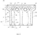
FIG. 2 is a front view of a flame distributor of a combustor according to an embodiment of the present invention. -
FIG. 3 is a left-side view of two flame distributors of a combustor according to an embodiment of the present invention. -
FIG. 4 is a front view of a combustor according to an embodiment of the present invention. -
FIG. 5 is an explosive view of a combustor according to an embodiment of the present invention. - In the following, only certain exemplary embodiments are briefly described. As will be appreciated by those skilled in the art, the described embodiments may be modified in various ways without departing from the spirit or scope of the present invention. Accordingly, the drawings and description are to be regarded as illustrative in nature rather than restrictive.
- In the description of the present invention, it is to be understood that orientations or positional relationships indicated by terms "center", "longitudinal", "transverse", "length", "width", "thickness", "upper", "lower", "front", "rear", "left", "right", "vertical", "horizontal", "top", "bottom", "inner", "outer", "clockwise", "anticlockwise", "axial", "radial", "circumferential" and the like are based on the orientations or positional relationships shown in the drawings, which are merely for ease of description of the present invention and simplicity of description, and are not intended to indicate or imply that the device or assembly referred to must have a particular orientation, or be constructed and operated in a particular orientation. It is therefore not to be construed as limiting the present invention.
- Furthermore, the terms "first" and "second" are used for descriptive purposes only and are not to be construed as indicating or implying relative importance or implicitly indicating the number of technical features indicated. Therefore, features defined with "first" and "second" may explicitly or implicitly include one or more such features. In the description of the present invention, "a plurality of" means two or more, unless specifically defined otherwise.
- In the present invention, unless expressly stated and defined otherwise, the terms "mounted", "coupled", "connected", "fixed", and the like are to be construed broadly, for example, either as fixed or detachable connections, or as integrated connection; it may be a mechanical connection, an electrical connection, or a communication; it may be a direct connection, or an indirect connection through an intermediary, or two components may be interconnected inside or in an interactive relationship with each other. Specific meaning of the above terms in the present invention may be understood by those ordinary skilled in the art, as the case may be.
- In the present invention, unless expressly stated and defined otherwise, reference to a first feature as being "above" or "below" a second feature may include reference to the first and second features being in direct contact, and reference to the first and second features not being in direct contact but being in contact by additional features therebetween. Furthermore, the first feature being "above", "over" and "on" the second feature includes the first feature being directly above and obliquely above the second feature, or merely indicates that the first feature has a higher horizontal height than the second feature. The first feature being "below", "underneath" and "under" the second feature includes the first feature being directly above and obliquely above the second feature, or merely indicates that the first feature has a lower horizontal height than the second feature.
- The following disclosure provides many different embodiments or examples for implementing different structures of the present invention. To simplify the disclosure of the present invention, components and arrangements of specific examples are described below. They are, of course, merely exemplary and are not intended to limit the present invention. In addition, in the present invention numerical references and/or reference letters may be repeated in various examples for purposes of simplicity and clarity, which does not inherently indicate a relationship between the various implementations and/or arrangements discussed.
- As shown in
FIG. 1 , which is a top view of acombustor 10 of the present embodiment, thecombustor 10 of the present embodiment includes a plurality offlame distributors 100 distributed side by side along a width direction of theflame distributor 100, and acooling water pipe 200 passing through the plurality offlame distributors 100, thecooling water pipe 200 is a U-shaped pipe including awater inlet pipe 210 and awater outlet pipe 220, to inlet and discharge water on a same side of thecombustor 10, preferably, thecooling water pipe 200 is integrally formed. - As shown in
FIG. 2 , which is a front view of one of theflame distributors 100, theflame distributor 100 of the present embodiment includes threeejection tubes 110 and two through holes (a water inlet pipe throughhole 131 and a water outlet pipe through hole 132), where two ends of thecooling water pipe 200 pass through corresponding through holes, respectively, i.e., the water inlet pipe throughhole 131 is used for allowing thewater inlet pipe 210 to pass through and be in close contact with thewater inlet pipe 210, and the water outlet pipe throughhole 132 is used for allowing thewater outlet pipe 220 to pass through and be in close contact with theoutlet pipe 220. - As shown in
FIG. 3 , which is a left-side view of twoadjacent flame distributors FIG. 1 andFIG. 2 , in the present embodiment theflame distributor 100 may be formed by afirst housing 100A snap-fitted with asecond housing 100B, i.e., a gas channel of theejection tube 100 is formed by an enclosure offirst housing 100A and thesecond housing 100B, the water inlet pipe throughhole 131 and the water outlet pipe throughhole 132 pass through thefirst housing 100A and thesecond housing 100B. Theflame distributor 100 further includes atop plate 120 which covers above the threeejection tubes 110 and is provided with a plurality offire holes 121. - Referring to
FIG. 2 andFIG. 3 , each of theejection tubes 110 is provided with anejection section 110A and agas outlet section 110B in a sequence according to a gas flow direction, where theejection section 110A has aninlet end 113, athroat 114, and anoutlet end 115, theejection tube 110 ejects gas vertically upward from theinlet end 113, after the gas passes through thethroat 114 and theoutlet section 110B, and is then discharged from thefire hole 121, it is ignited by anigniter 160 to form a flame. In order to prevent the flame from being too strong due to an excessive force for ejecting the gas flow, end surfaces of thegas outlet section 110B of theejection tube 110 are inclined to both sides, to form a flow guide inclined plane (including a first flow guideinclined plane 111A inclined to the left and a second flow guideinclined plane 111B inclined to the right). - A
throat 114 is provided at a minimum cross-section of theejection section 110A, i.e., gas passes through thethroat 114 with the smallest passage area. A maximum width of thethroat 114 allowing gas to pass through is D1, for example, when the cross-sectional shape of thethroat 114 is circular, the maximum width D1 is the diameter of thethroat 114; when the cross-sectional shape of thethroat 114 is rectangular, the maximum width D1 is the longest diagonal of thethroat 114. - Decreasing the maximum width D1 of the
throat 114 may reduce the size of theflame distributor 100, and increasing the length HI of theejection section 110A and the maximum width D1 of thethroat 114 may reduce the energy loss coefficient, thereby increasing the ejection coefficient and making the mixing of gas and air more uniform. Experimental results show that when H1=6D1, the energy loss coefficient of combustor ejection is about 2.2; when HI = 8D1, the energy loss coefficient of combustor ejection is about 1.8; when 8.5D1≤H1≤9.5D1, the energy loss coefficient of the combustor ejection is about 1.5. As reducing the energy loss coefficient is conducive to increasing the ejection coefficient, when the ejection coefficient increases, the volume of actual combustion products will increase, leading to a sharp decrease in the combustion temperature, which may in turn reduce a thermodynamic oxidation reaction, so that an emission of nitrogen oxides is reduced (the thermodynamic oxidation reaction refers to an oxidation reaction of nitrogen and oxygen in the air at high temperature, to generate nitrogen oxides, experiments show that as the reaction temperature increases, the oxidation reaction rate increases exponentially). - Preferably, the
ejection section 110A includes a premixing section 110A1 and a diffusion section 110A2, theejection tube 110 has the uniform cross-sectional shape in the premixing section 110A1, a length of the premixing section 110A1 is H11, where 2D1≤H11≤3D1; the diffusion section 110A2 deviates gradually from a central axis of theejection tube 110 along a gas flow direction, and a length of the diffusion section 110A2 is H12, where 3.5D1≤H12≤4.5D1. - Further, a length H2 of the
gas outlet section 110B is as such, H2≤30%H1, to reduce the size of theflame distributor 100. - Preferably, 11mm≤D1≤14mm, and the cross-sectional area of the gas channel formed by each
flame distributor 100 at thethroat 114 is 33mm2 ∼ 42mm2, therefore, increasing the number of ejection tubes facilitates reducing the maximum width of thethroat 114, to reduce the size of theflame distributor 100. It should be noted that in the present embodiment, the number of theejection tubes 110 may be three or more than three, and an increase of the number of theejection tubes 110 may increase the ejection coefficient, thereby increasing the amount of ejected gas. - Further, a maximum width D2 of the
inlet end 113 is greater than or equal to a maximum width D3 of theoutlet end 115, preferably, D2=D3, and the center of theinlet end 113 is concave towards theoutlet end 115, to form an arc-shapedsection 113A, as shown inFIG. 2 , theinlet end 113 with this large-round-corner design may make the gas flow smoother and increase the amount of air ejected through the gas, preferably, D2≥18mm. - As shown in
FIG. 2 andFIG. 3 , theejection tube 110 further has adiverter 112, which includes afirst recess 112A formed by recessing thefirst housing 100A into a cavity of theejection tube 110, and asecond recess 112B formed by recessing thesecond housing 100B into a cavity of theejection tube 110. Thediverter 112 is used for diverting gas, that is, a part of gas is influenced by the resistance of thediverter 112 to be diverted to two sides of theejection tube 110, ejected fromfire holes 121 corresponding to the two sides of theejection tube 110, and burned to form a flame; while the other part of gas flows vertically upward from the gas channel between thefirst recess 112A and thesecond recess 112B, ejected fromfire holes 121 corresponding to the center of theejection tube 110, and then burned to form a flame. - The angle α of an apex corner 112C of the
diverter 112 is preferably 45 degrees to 85 degrees, that is, the diverting angle of the apex corner 112C for diverting the gas towards both sides thereof is preferably 45° to 85°, to reduce the resistance of gas flow. -
FIG. 4 and FIG. 5 show a front view and an explosive view of thecombustor 10, respectively, that is, a view when a plurality offlame distributors 100 are combined together, in this embodiment, thecombustor 10 further includes agas distribution device 300 provided below each of theejection tubes 110, a gas passage is provided in thegas distribution device 300, and is communicated with theejection tubes 110 through a plurality ofnozzles 310. In the operation of thecombustor 10, a gas valve connected to avalve connection 320 is opened, gas enters theejection tube 110 through thenozzle 310, and the diameter D0 of thenozzle 310 is smaller than the maximum width D1 of thethroat 114, preferably, D1=2D0, so that more gas is ejected into theejection tube 110, to increase the ejection coefficient and reduce the generation of nitrogen oxides. - Preferably, in the present embodiment, the water inlet pipe through
hole 131 and the water outlet pipe throughhole 132 are located between twoadjacent ejection tubes 110, respectively, tops of the water inlet pipe throughhole 131 and the water outlet pipe throughhole 132 are preferably arranged at the same horizontal plane, the top E1 of the water inlet pipe throughhole 131 should be higher than the bottom E2 of thediverter 112, so that the position of the coolingwater pipe 200 is close to thetop plate 120, thereby improving the cooling efficiency and reducing the generation of nitrogen oxides. - In the present embodiment, the
combustor 10 is of a vertical structure, the direction of a gas flow is vertical after gas is ejected from thenozzle 310, and gas and air are mixed in theejection tube 110 and then ignited at thefire hole 121, the large-round-corner inlet end 113 may eject more gas and reduce the diameter of thethroat 114, on the premise of reducing the size of theflame distributor 100, increasing the length of theejection section 110A allows for more uniform gas mixing. The design of at least three ejection tubes may not only increase the amount of ejected gas, but also increase the number of the correspondingnozzles 310, thereby further improving the ejection coefficient and reducing the generation of nitrogen oxides. Experiments show that by applying the flow channel design of the present application, the nitrogen oxide emission may be reduced from 80ppm (number of particles per cubic centimeter) to 20ppm. - Further, the
flame distributor 100 further includes apitch positioning structure 150 provided outside theejection tube 110, eachpitch positioning structure 150 includes afirst protrusion 151 and asecond protrusion 152 symmetrically provided, where thefirst protrusion 151 is formed by protruding thefirst housing 100A towards the outside of theejection tube 110, and thesecond protrusion 152 is formed by protruding thesecond housing 100B towards the outside of theejection tube 110. - As shown in
FIG. 3 , the distance between thefirst protrusion 151 and thesecond protrusion 152 is D5, and the outer diameter of theinlet end 113 of theejection tube 110 is D4, where D4 is equal to D5, so that the side walls of the inlet ends 113 of the twoadjacent flame distributors pitch positioning structure 150 of the twoadjacent flame distributors first protrusion 151 of theflame distributor 103 abuts against thesecond protrusion 152 of theflame distributor 104. - It should be noted that in the present embodiment, the number of
pitch positioning structures 150 are not limited, for example, onepitch positioning structure 150 may be provided outside one of theejection tubes 110, or onepitch positioning structure 150 may be provided outside eachejection tube 110. It is feasible as long as the side walls of the inlet ends of the twoadjacent flame distributors 100 may abut to each other, and thepitch positioning structures 150 of the two adjacent flame distributors may abut to each other. - In the present embodiment, the
pitch positioning structure 150 may make the fixation between a plurality offlame distributors 100 more firmly, and reduce shaking or vibration, thereby reducing noise generated by thecombustor 10 during operation. - Further, as shown in
FIG. 4 and FIG. 5 , a plurality offlame distributors 100 include afirst flame distributor 101 and asecond flame distributor 102 arranged at the end of thecombustor 10, thecombustor 10 further includes a firstpressing plate 171, a secondpressing plate 172, a connectingpiece 180, afirst fastener 191 and asecond fastener 192. The firstpressing plate 171 is positioned on the outer side of thefirst flame distributor 101, and the secondpressing plate 172 is positioned on the outer side of thesecond flame distributor 102; the connectingpiece 180 passes through the firstpressing plate 171,respective flame distributors 100 and the secondpressing plate 172, sequentially; further, the connectingpiece 180 is fixedly connected to the firstpressing plate 171 through thefirst fastener 191, and the connectingpiece 180 is fixedly connected to the secondpressing plate 172 through thesecond fastener 192, so that the firstpressing plate 171 and the secondpressing plate 172 press eachflame distributor 100 from both ends of thecombustor 10 tightly. Preferably, in the present embodiment, the connectingpiece 180 may be a double-thread screw, while thefirst fastener 191 and thesecond fastener 192 may be bolts. - As another aspect of embodiments of the present invention, in the present embodiment, it is also provided a flue gas water heater including the combustor according to above embodiments. Other configurations of the gas water heater of the present embodiment may employ various technical schemes known to those ordinary skilled in the art now and in the future, and will not be described in detail herein. According to the flue gas water heater of the present embodiment, due to the adoption of the above-mentioned
combustor 10, a sufficient amount of gas may still be ejected without a fan, so that the ejection coefficient is improved, and the generation of nitrogen oxides is reduced. - As another aspect of embodiments of the present invention, in the present embodiment, it is also provided a wall-mounted furnace including a combustor according to above-described embodiments. Other configurations of the wall-mounted furnace of the present embodiment may employ various technical schemes known to those ordinary skilled in the art now and in the future, and will not be described in detail herein.
- The above-mentioned content only refers to preferred embodiments of the present invention, which should not be regarded as limiting the protection scope of the present invention, within the technical scope disclosed by the present invention, it is readily envisaged by any skilled in the art that various modifications and variations can be made, and such modifications and variations are considered to be within the scope of the present application. Therefore, the protection scope of the present invention should be subject to the protection scope of the claims.
| 10: combustor; | 100: flame distributor; | |
| 100A: first housing; | 100B: second housing; | 110: ejection tube; |
| 111A: first flow guide inclined plane; | 111B: second flow guide inclined plane; | 112: diverter; |
| 112A: first recess; | 112B: second recess; | 112C: apex corner; |
| 110A: ejection section; | 110B: gas outlet section; | 113: inlet end; |
| 113A: arc-shaped cross-section; | 114: throat; | 115: outlet end; |
| 120: top plate; | 121: fire hole; | 131: water inlet pipe through hole |
| 132: water outlet pipe through hole; | 150: pitch positioning structure; | |
| 151: first protrusion; | 152: second protrusion; | 160: igniter; |
| 101: first flame distributor; | 102: second flame distributor; | |
| 103, 104: two adjacent flame distributors; | ||
| 171: first pressing plate; | 172: second pressing plate; | 180: connecting piece; |
| 191: first fastener; | 192: second fastener; | 200: cooling water pipe; |
| 210: water inlet pipe; | 220: water outlet pipe; | |
| 300: gas distribution device; | 310: nozzle; | 320: valve connection. |
Claims (10)
- A combustor, characterized by comprising a plurality of flame distributors, the plurality of flame distributors are distributed side by side along a width direction, the flame distributor comprises at least three ejection tubes, the ejection tube is provided with an ejection section and a gas outlet section in a sequence according to a gas flow direction, and the ejection tube comprises:a throat, being provided at a minimum cross-section of the ejection section, wherein a length of the ejection section is H1, and a maximum width of the throat allowing gas to pass through is D1, wherein 8.5D1≤H1≤9.5D1; anda diverter, being provided in the gas outlet section, having an apex corner for diverting gas towards two sides, an angle of the apex corner being 45 degrees to 85 degrees.
- The combustor according to claim 1, characterized in that the ejection section comprises:a premixing section, the ejection tube has a uniform cross-sectional shape in the premixing section, a length of the premixing section is H11, wherein 2D1≤H11≤3D1; anda diffusion section, gradually deviating from a central axis of the ejection tube along a gas flow direction, a length of the diffusion section is H12, wherein 3.5D1≤H12≤4.5D1.
- The combustor according to claim 1, characterized in that the ejection section has an inlet end and an outlet end, a maximum width of the inlet end being greater than or equal to a maximum width of the outlet end, and the maximum width of the inlet end being greater than or equal to 18mm.
- The combustor according to claim 3, characterized in that the inlet end has an arc-shaped cross-section, the arc-shaped cross-section being formed by recessing a center of the inlet end towards the outlet end.
- The combustor according to claim 1, characterized in that 11mm≤D1≤14mm.
- The combustor according to claim 1, characterized in that a length of the gas outlet section is less than or equal to 30%H1.
- The combustor according to claim 1, characterized in that the combustor further comprises a gas distribution device , the gas distribution device provided below each of the ejection tube, a plurality of gas passages being provided in the gas distribution device , the gas distribution device further comprising a plurality of nozzles , the gas distribution device being communicated with the ejection tubesthrough the nozzles , the nozzle having a diameter D0, wherein D1=2D0.
- The combustor according to any one of claims 1 to 7, characterized in that the flame distributor comprises a first housing and a second housing, the fist housing and the second housing are symmetrically arranged, a gas channel of the ejection tube being formed by an enclosure of the first housing and the second housing; the diverter comprises a first recess and a second recess , the first recess and the second recess are symmetrically arranged, the first recess being formed by recessing the first housing into a cavity of the ejection tube, the second recess being formed by recessing the second housing into a cavity of the ejection tube, a gas channel being provided between the first recess and the second recess; the flame distributor further comprises a top plate covering a top of the ejection tube, the top plate being provided with a plurality of fire holes; and the first housing is snap-fitted with the second housing, and the top plate is snap-fitted with the first housing and with the second housing.
- The combustor according to any one of claims 1 to 7, characterized in that the diverter further comprises at least two through holes, the through hole being provided between two adjacent ejection tubes, the through hole is configure to allow a cooling water pipe to pass through and being in close contact with the cooling water pipe.
- A water heater, characterized by comprising a combustor according to any one of claims 1 to 9.
Applications Claiming Priority (2)
| Application Number | Priority Date | Filing Date | Title |
|---|---|---|---|
| CN201810462349.5A CN108548178B (en) | 2018-05-15 | 2018-05-15 | Burner and water heater using it |
| PCT/CN2018/091102 WO2019218414A1 (en) | 2018-05-15 | 2018-06-13 | Combustor and water heater using same |
Publications (3)
| Publication Number | Publication Date |
|---|---|
| EP3795900A1 true EP3795900A1 (en) | 2021-03-24 |
| EP3795900A4 EP3795900A4 (en) | 2021-06-16 |
| EP3795900B1 EP3795900B1 (en) | 2025-10-01 |
Family
ID=63494909
Family Applications (1)
| Application Number | Title | Priority Date | Filing Date |
|---|---|---|---|
| EP18919158.8A Active EP3795900B1 (en) | 2018-05-15 | 2018-06-13 | Combustor and water heater using same |
Country Status (4)
| Country | Link |
|---|---|
| EP (1) | EP3795900B1 (en) |
| CN (2) | CN110762526B (en) |
| ES (1) | ES3050882T3 (en) |
| WO (1) | WO2019218414A1 (en) |
Families Citing this family (6)
| Publication number | Priority date | Publication date | Assignee | Title |
|---|---|---|---|---|
| CN109695875A (en) * | 2019-01-02 | 2019-04-30 | 刘维 | A kind of more injection tubular type fire pieces |
| CN110145794A (en) * | 2019-04-12 | 2019-08-20 | 万家乐热能科技有限公司 | A kind of method and burnt gas wall hanging furnace reducing wall-hung boiler discharged nitrous oxides |
| CN113124407A (en) * | 2019-12-31 | 2021-07-16 | 芜湖美的厨卫电器制造有限公司 | Fire row sheet for combustor and combustor with fire row sheet |
| CN115183235B (en) * | 2021-04-02 | 2025-03-04 | 芜湖美的厨卫电器制造有限公司 | Nozzles, gas distribution devices, burners and gas water heaters |
| CN115076690B (en) * | 2022-07-07 | 2025-07-29 | 珠海格力电器股份有限公司 | Ejector, ejection assembly and gas stove |
| CN115425255B (en) * | 2022-08-25 | 2025-04-08 | 北京航天动力研究所 | Ejector and gas supply circulation system for fuel cell |
Family Cites Families (13)
| Publication number | Priority date | Publication date | Assignee | Title |
|---|---|---|---|---|
| DE3142903A1 (en) * | 1981-10-29 | 1983-06-01 | Ing. Paul Joosten Verpackungstechnik, 4180 Goch | Burner |
| AT396018B (en) * | 1990-08-20 | 1993-05-25 | Vaillant Gmbh | AREA BURNER WITH SEVERAL COMBUSTION CHAMBERS |
| AT404179B (en) * | 1995-05-02 | 1998-09-25 | Vaillant Gmbh | WATER COOLED BURNER |
| DE102006011727B3 (en) * | 2006-03-14 | 2007-11-22 | Webasto Ag | Combined heating / hot water system for mobile applications |
| CN103591581B (en) * | 2013-11-15 | 2015-11-18 | 中冶南方(武汉)威仕工业炉有限公司 | Automatic ignition multi-unit combined flat plate heating device |
| CN203784951U (en) * | 2014-04-13 | 2014-08-20 | 文成县刀锋科技有限公司 | Injection commingler |
| KR20150002484U (en) * | 2014-07-22 | 2015-06-25 | 이수정 | an easy to shop for the manufacture of jean fryerburner |
| CN204084365U (en) * | 2014-08-18 | 2015-01-07 | 中山市星立方厨房科技有限公司 | A Burner with Improved Ignition Needle Installation |
| CN205026669U (en) * | 2015-08-06 | 2016-02-10 | 广州迪森家用锅炉制造有限公司 | A combustor for gas heating water heater or gas heater |
| TWI621813B (en) * | 2016-09-26 | 2018-04-21 | Grand Mate Co Ltd | Burner |
| CN106642109B (en) * | 2017-01-27 | 2023-03-10 | 黄婉平 | Low nitrogen oxide burner of gas heating water heater |
| CN107620963A (en) * | 2017-11-01 | 2018-01-23 | 芜湖美的厨卫电器制造有限公司 | Burner and there is its water heater |
| CN208205002U (en) * | 2018-05-15 | 2018-12-07 | 芜湖美的厨卫电器制造有限公司 | Burner and the water heater for applying it |
-
2018
- 2018-05-15 CN CN201911063413.3A patent/CN110762526B/en active Active
- 2018-05-15 CN CN201810462349.5A patent/CN108548178B/en active Active
- 2018-06-13 EP EP18919158.8A patent/EP3795900B1/en active Active
- 2018-06-13 ES ES18919158T patent/ES3050882T3/en active Active
- 2018-06-13 WO PCT/CN2018/091102 patent/WO2019218414A1/en not_active Ceased
Also Published As
| Publication number | Publication date |
|---|---|
| ES3050882T3 (en) | 2025-12-23 |
| CN108548178A (en) | 2018-09-18 |
| EP3795900B1 (en) | 2025-10-01 |
| CN110762526A (en) | 2020-02-07 |
| EP3795900A4 (en) | 2021-06-16 |
| WO2019218414A1 (en) | 2019-11-21 |
| CN108548178B (en) | 2019-11-26 |
| CN110762526B (en) | 2022-02-22 |
Similar Documents
| Publication | Publication Date | Title |
|---|---|---|
| EP3795900A1 (en) | Combustor and water heater using same | |
| CN106642109B (en) | Low nitrogen oxide burner of gas heating water heater | |
| US11371698B2 (en) | Burner and water heater | |
| CN108916872B (en) | Gas water heater and burner thereof | |
| CN207065570U (en) | Burner and gas heater | |
| CN212618292U (en) | Combustor and gas water heater | |
| CN207622014U (en) | Burner and water heater with it | |
| US6929470B1 (en) | Low NOx duct burner | |
| CN208205002U (en) | Burner and the water heater for applying it | |
| CN220958457U (en) | Fire row assembly and combustor | |
| CN220169449U (en) | Furnace end and have its combustor | |
| WO2003029724A1 (en) | Boiler-steam generator | |
| CN207849364U (en) | Distributor and burner and water heater with it | |
| CN115574317B (en) | A fully top-mounted air intake stove | |
| CN113757663B (en) | Burner and stove with burner | |
| CN221375666U (en) | Burner and domestic electrical appliance | |
| EP3584499A1 (en) | Flame spreader as well as burner and water heater using same | |
| CN222798986U (en) | Burners and cooking appliances | |
| CN222798985U (en) | Burners and cooking appliances | |
| WO2019219037A1 (en) | Distributor and combustor and water heater having same | |
| CN109724078B (en) | Distributor and combustor and water heater with same | |
| CN112856411B (en) | Injection structure and combustor comprising same | |
| CN222143058U (en) | Fire grate and burner | |
| CN120521210A (en) | Gas stoves and burners | |
| US20090029302A1 (en) | System of close coupled rapid mix burner cells |
Legal Events
| Date | Code | Title | Description |
|---|---|---|---|
| STAA | Information on the status of an ep patent application or granted ep patent |
Free format text: STATUS: THE INTERNATIONAL PUBLICATION HAS BEEN MADE |
|
| PUAI | Public reference made under article 153(3) epc to a published international application that has entered the european phase |
Free format text: ORIGINAL CODE: 0009012 |
|
| STAA | Information on the status of an ep patent application or granted ep patent |
Free format text: STATUS: REQUEST FOR EXAMINATION WAS MADE |
|
| 17P | Request for examination filed |
Effective date: 20201215 |
|
| AK | Designated contracting states |
Kind code of ref document: A1 Designated state(s): AL AT BE BG CH CY CZ DE DK EE ES FI FR GB GR HR HU IE IS IT LI LT LU LV MC MK MT NL NO PL PT RO RS SE SI SK SM TR |
|
| AX | Request for extension of the european patent |
Extension state: BA ME |
|
| A4 | Supplementary search report drawn up and despatched |
Effective date: 20210514 |
|
| RIC1 | Information provided on ipc code assigned before grant |
Ipc: F23D 14/08 20060101AFI20210508BHEP Ipc: F23D 14/46 20060101ALI20210508BHEP Ipc: F23D 14/84 20060101ALI20210508BHEP Ipc: F23D 14/64 20060101ALI20210508BHEP Ipc: F23D 14/70 20060101ALI20210508BHEP Ipc: F23D 14/04 20060101ALI20210508BHEP Ipc: F23D 14/78 20060101ALI20210508BHEP |
|
| DAV | Request for validation of the european patent (deleted) | ||
| DAX | Request for extension of the european patent (deleted) | ||
| STAA | Information on the status of an ep patent application or granted ep patent |
Free format text: STATUS: EXAMINATION IS IN PROGRESS |
|
| 17Q | First examination report despatched |
Effective date: 20240418 |
|
| GRAP | Despatch of communication of intention to grant a patent |
Free format text: ORIGINAL CODE: EPIDOSNIGR1 |
|
| STAA | Information on the status of an ep patent application or granted ep patent |
Free format text: STATUS: GRANT OF PATENT IS INTENDED |
|
| INTG | Intention to grant announced |
Effective date: 20250610 |
|
| RAP3 | Party data changed (applicant data changed or rights of an application transferred) |
Owner name: MIDEA GROUP CO., LTD. Owner name: WUHU MIDEA KITCHEN AND BATHAPPLIANCES MFG. CO., LTD. |
|
| GRAS | Grant fee paid |
Free format text: ORIGINAL CODE: EPIDOSNIGR3 |
|
| GRAA | (expected) grant |
Free format text: ORIGINAL CODE: 0009210 |
|
| STAA | Information on the status of an ep patent application or granted ep patent |
Free format text: STATUS: THE PATENT HAS BEEN GRANTED |
|
| AK | Designated contracting states |
Kind code of ref document: B1 Designated state(s): AL AT BE BG CH CY CZ DE DK EE ES FI FR GB GR HR HU IE IS IT LI LT LU LV MC MK MT NL NO PL PT RO RS SE SI SK SM TR |
|
| REG | Reference to a national code |
Ref country code: GB Ref legal event code: FG4D Ref country code: CH Ref legal event code: F10 Free format text: ST27 STATUS EVENT CODE: U-0-0-F10-F00 (AS PROVIDED BY THE NATIONAL OFFICE) Effective date: 20251001 |
|
| REG | Reference to a national code |
Ref country code: DE Ref legal event code: R096 Ref document number: 602018086129 Country of ref document: DE |
|
| REG | Reference to a national code |
Ref country code: IE Ref legal event code: FG4D |
|
| REG | Reference to a national code |
Ref country code: ES Ref legal event code: FG2A Ref document number: 3050882 Country of ref document: ES Kind code of ref document: T3 Effective date: 20251223 |
|
| REG | Reference to a national code |
Ref country code: NL Ref legal event code: MP Effective date: 20251001 |
|
| REG | Reference to a national code |
Ref country code: AT Ref legal event code: MK05 Ref document number: 1842809 Country of ref document: AT Kind code of ref document: T Effective date: 20251001 |
|
| PG25 | Lapsed in a contracting state [announced via postgrant information from national office to epo] |
Ref country code: NL Free format text: LAPSE BECAUSE OF FAILURE TO SUBMIT A TRANSLATION OF THE DESCRIPTION OR TO PAY THE FEE WITHIN THE PRESCRIBED TIME-LIMIT Effective date: 20251001 |
|
| REG | Reference to a national code |
Ref country code: LT Ref legal event code: MG9D |
|
| PG25 | Lapsed in a contracting state [announced via postgrant information from national office to epo] |
Ref country code: NO Free format text: LAPSE BECAUSE OF FAILURE TO SUBMIT A TRANSLATION OF THE DESCRIPTION OR TO PAY THE FEE WITHIN THE PRESCRIBED TIME-LIMIT Effective date: 20260101 |
|
| PG25 | Lapsed in a contracting state [announced via postgrant information from national office to epo] |
Ref country code: AT Free format text: LAPSE BECAUSE OF FAILURE TO SUBMIT A TRANSLATION OF THE DESCRIPTION OR TO PAY THE FEE WITHIN THE PRESCRIBED TIME-LIMIT Effective date: 20251001 Ref country code: FI Free format text: LAPSE BECAUSE OF FAILURE TO SUBMIT A TRANSLATION OF THE DESCRIPTION OR TO PAY THE FEE WITHIN THE PRESCRIBED TIME-LIMIT Effective date: 20251001 Ref country code: HR Free format text: LAPSE BECAUSE OF FAILURE TO SUBMIT A TRANSLATION OF THE DESCRIPTION OR TO PAY THE FEE WITHIN THE PRESCRIBED TIME-LIMIT Effective date: 20251001 |
|
| PG25 | Lapsed in a contracting state [announced via postgrant information from national office to epo] |
Ref country code: RS Free format text: LAPSE BECAUSE OF FAILURE TO SUBMIT A TRANSLATION OF THE DESCRIPTION OR TO PAY THE FEE WITHIN THE PRESCRIBED TIME-LIMIT Effective date: 20260101 |
|
| PG25 | Lapsed in a contracting state [announced via postgrant information from national office to epo] |
Ref country code: IS Free format text: LAPSE BECAUSE OF FAILURE TO SUBMIT A TRANSLATION OF THE DESCRIPTION OR TO PAY THE FEE WITHIN THE PRESCRIBED TIME-LIMIT Effective date: 20260201 |
|
| PG25 | Lapsed in a contracting state [announced via postgrant information from national office to epo] |
Ref country code: PT Free format text: LAPSE BECAUSE OF FAILURE TO SUBMIT A TRANSLATION OF THE DESCRIPTION OR TO PAY THE FEE WITHIN THE PRESCRIBED TIME-LIMIT Effective date: 20260202 Ref country code: CZ Free format text: LAPSE BECAUSE OF FAILURE TO SUBMIT A TRANSLATION OF THE DESCRIPTION OR TO PAY THE FEE WITHIN THE PRESCRIBED TIME-LIMIT Effective date: 20251001 |
|
| PG25 | Lapsed in a contracting state [announced via postgrant information from national office to epo] |
Ref country code: PL Free format text: LAPSE BECAUSE OF FAILURE TO SUBMIT A TRANSLATION OF THE DESCRIPTION OR TO PAY THE FEE WITHIN THE PRESCRIBED TIME-LIMIT Effective date: 20251001 |
|
| PG25 | Lapsed in a contracting state [announced via postgrant information from national office to epo] |
Ref country code: LV Free format text: LAPSE BECAUSE OF FAILURE TO SUBMIT A TRANSLATION OF THE DESCRIPTION OR TO PAY THE FEE WITHIN THE PRESCRIBED TIME-LIMIT Effective date: 20251001 |