EP3795818A1 - Structure for attaching metal diaphragm damper - Google Patents
Structure for attaching metal diaphragm damper Download PDFInfo
- Publication number
- EP3795818A1 EP3795818A1 EP19803571.9A EP19803571A EP3795818A1 EP 3795818 A1 EP3795818 A1 EP 3795818A1 EP 19803571 A EP19803571 A EP 19803571A EP 3795818 A1 EP3795818 A1 EP 3795818A1
- Authority
- EP
- European Patent Office
- Prior art keywords
- portions
- housing
- diaphragms
- outer peripheral
- metal diaphragm
- Prior art date
- Legal status (The legal status is an assumption and is not a legal conclusion. Google has not performed a legal analysis and makes no representation as to the accuracy of the status listed.)
- Withdrawn
Links
Images


Classifications
-
- F—MECHANICAL ENGINEERING; LIGHTING; HEATING; WEAPONS; BLASTING
- F02—COMBUSTION ENGINES; HOT-GAS OR COMBUSTION-PRODUCT ENGINE PLANTS
- F02M—SUPPLYING COMBUSTION ENGINES IN GENERAL WITH COMBUSTIBLE MIXTURES OR CONSTITUENTS THEREOF
- F02M59/00—Pumps specially adapted for fuel-injection and not provided for in groups F02M39/00 -F02M57/00, e.g. rotary cylinder-block type of pumps
- F02M59/44—Details, components parts, or accessories not provided for in, or of interest apart from, the apparatus of groups F02M59/02 - F02M59/42; Pumps having transducers, e.g. to measure displacement of pump rack or piston
-
- F—MECHANICAL ENGINEERING; LIGHTING; HEATING; WEAPONS; BLASTING
- F02—COMBUSTION ENGINES; HOT-GAS OR COMBUSTION-PRODUCT ENGINE PLANTS
- F02M—SUPPLYING COMBUSTION ENGINES IN GENERAL WITH COMBUSTIBLE MIXTURES OR CONSTITUENTS THEREOF
- F02M55/00—Fuel-injection apparatus characterised by their fuel conduits or their venting means; Arrangements of conduits between fuel tank and pump F02M37/00
- F02M55/04—Means for damping vibrations or pressure fluctuations in injection pump inlets or outlets
-
- F—MECHANICAL ENGINEERING; LIGHTING; HEATING; WEAPONS; BLASTING
- F02—COMBUSTION ENGINES; HOT-GAS OR COMBUSTION-PRODUCT ENGINE PLANTS
- F02M—SUPPLYING COMBUSTION ENGINES IN GENERAL WITH COMBUSTIBLE MIXTURES OR CONSTITUENTS THEREOF
- F02M55/00—Fuel-injection apparatus characterised by their fuel conduits or their venting means; Arrangements of conduits between fuel tank and pump F02M37/00
- F02M55/02—Conduits between injection pumps and injectors, e.g. conduits between pump and common-rail or conduits between common-rail and injectors
- F02M55/025—Common rails
-
- F—MECHANICAL ENGINEERING; LIGHTING; HEATING; WEAPONS; BLASTING
- F02—COMBUSTION ENGINES; HOT-GAS OR COMBUSTION-PRODUCT ENGINE PLANTS
- F02M—SUPPLYING COMBUSTION ENGINES IN GENERAL WITH COMBUSTIBLE MIXTURES OR CONSTITUENTS THEREOF
- F02M59/00—Pumps specially adapted for fuel-injection and not provided for in groups F02M39/00 -F02M57/00, e.g. rotary cylinder-block type of pumps
- F02M59/20—Varying fuel delivery in quantity or timing
- F02M59/36—Varying fuel delivery in quantity or timing by variably-timed valves controlling fuel passages to pumping elements or overflow passages
-
- F—MECHANICAL ENGINEERING; LIGHTING; HEATING; WEAPONS; BLASTING
- F02—COMBUSTION ENGINES; HOT-GAS OR COMBUSTION-PRODUCT ENGINE PLANTS
- F02M—SUPPLYING COMBUSTION ENGINES IN GENERAL WITH COMBUSTIBLE MIXTURES OR CONSTITUENTS THEREOF
- F02M59/00—Pumps specially adapted for fuel-injection and not provided for in groups F02M39/00 -F02M57/00, e.g. rotary cylinder-block type of pumps
- F02M59/44—Details, components parts, or accessories not provided for in, or of interest apart from, the apparatus of groups F02M59/02 - F02M59/42; Pumps having transducers, e.g. to measure displacement of pump rack or piston
- F02M59/445—Selection of particular materials
-
- F—MECHANICAL ENGINEERING; LIGHTING; HEATING; WEAPONS; BLASTING
- F02—COMBUSTION ENGINES; HOT-GAS OR COMBUSTION-PRODUCT ENGINE PLANTS
- F02M—SUPPLYING COMBUSTION ENGINES IN GENERAL WITH COMBUSTIBLE MIXTURES OR CONSTITUENTS THEREOF
- F02M59/00—Pumps specially adapted for fuel-injection and not provided for in groups F02M39/00 -F02M57/00, e.g. rotary cylinder-block type of pumps
- F02M59/44—Details, components parts, or accessories not provided for in, or of interest apart from, the apparatus of groups F02M59/02 - F02M59/42; Pumps having transducers, e.g. to measure displacement of pump rack or piston
- F02M59/48—Assembling; Disassembling; Replacing
-
- F—MECHANICAL ENGINEERING; LIGHTING; HEATING; WEAPONS; BLASTING
- F02—COMBUSTION ENGINES; HOT-GAS OR COMBUSTION-PRODUCT ENGINE PLANTS
- F02M—SUPPLYING COMBUSTION ENGINES IN GENERAL WITH COMBUSTIBLE MIXTURES OR CONSTITUENTS THEREOF
- F02M2200/00—Details of fuel-injection apparatus, not otherwise provided for
- F02M2200/31—Fuel-injection apparatus having hydraulic pressure fluctuations damping elements
- F02M2200/315—Fuel-injection apparatus having hydraulic pressure fluctuations damping elements for damping fuel pressure fluctuations
-
- F—MECHANICAL ENGINEERING; LIGHTING; HEATING; WEAPONS; BLASTING
- F02—COMBUSTION ENGINES; HOT-GAS OR COMBUSTION-PRODUCT ENGINE PLANTS
- F02M—SUPPLYING COMBUSTION ENGINES IN GENERAL WITH COMBUSTIBLE MIXTURES OR CONSTITUENTS THEREOF
- F02M2200/00—Details of fuel-injection apparatus, not otherwise provided for
- F02M2200/80—Fuel injection apparatus manufacture, repair or assembly
- F02M2200/8084—Fuel injection apparatus manufacture, repair or assembly involving welding or soldering
-
- F—MECHANICAL ENGINEERING; LIGHTING; HEATING; WEAPONS; BLASTING
- F02—COMBUSTION ENGINES; HOT-GAS OR COMBUSTION-PRODUCT ENGINE PLANTS
- F02M—SUPPLYING COMBUSTION ENGINES IN GENERAL WITH COMBUSTIBLE MIXTURES OR CONSTITUENTS THEREOF
- F02M2200/00—Details of fuel-injection apparatus, not otherwise provided for
- F02M2200/90—Selection of particular materials
Definitions
- the present invention relates to a structure for attaching a metal diaphragm damper for pulsation absorption that is used at a position where pulsation is generated in a high-pressure fuel pump and the like.
- a high-pressure fuel pump for pumping fuel, which is supplied from a fuel tank, to an injector.
- the high-pressure fuel pump pressurizes and discharges fuel by the reciprocation of a plunger that is driven by the rotation of a cam shaft of an internal-combustion engine. Since pulsation is generated in a fuel chamber due to a change in the amount of fuel discharged to the injector from the high-pressure fuel pump or a change in the amount of fuel injected from the injector, a metal diaphragm damper for reducing pulsation generated in the fuel chamber is generally built in the high-pressure fuel pump.
- two disc-shaped diaphragms are welded to each other at the outer peripheral edge portions thereof, so that a hermetically sealed space filled with gas having a predetermined pressure is formed in a metal diaphragm damper disclosed in Patent Citation 1; and the metal diaphragm damper is provided in a fuel chamber.
- the fuel chamber is a space formed between a housing and a housing cover, and an annular attachment member is mounted on the inner peripheral surface of the fuel chamber by frictional engagement.
- the attachment member includes clip-shaped holders at a plurality of positions thereon in a circumferential direction and the outer peripheral edge portions of the diaphragms are held by the holders, so that the metal diaphragm damper is installed so as to partition the fuel chamber. Further, fuel can flow around to the spaces formed on both the surface side and back side of the metal diaphragm damper in the fuel chamber through a radial gap between the attachment member and the metal diaphragm damper.
- the metal diaphragm damper Since the respective diaphragms of the metal diaphragm damper are elastically deformed by fuel pressure accompanied by pulsation, the volume of the fuel chamber can be changed and pulsation is reduced.
- the metal diaphragm damper is adapted to be capable of reducing pulsation while the outer peripheral edge portions of the diaphragms or the attachment member is deformed and both the diaphragms are integrally moved to the other side when the metal diaphragm damper receives pulsation accompanied by shock waves from one side thereof.
- Patent Citation 1 JP 2014-190188 A (page 7, FIG. 2 )
- the present invention has been made in consideration of such problems, and an object of the present invention is to provide a structure for attaching a metal diaphragm damper that can fulfill an excellent pulsation-reducing function with a simple structure.
- a structure for attaching a metal diaphragm damper includes: a housing; a housing cover that cooperates with the housing to define a space between the housing and the housing cover; and a pair of diaphragms each formed in a disk shape, the pair of diaphragms having weld portions on an outer periphery side thereof, the weld portions being welded to each other in an annular shape to form the metal diaphragm damper of which inside is filled with gas, the metal diaphragm damper being attached to the housing and the housing cover so as to be disposed in the space between the housing and the housing cover, wherein the pair of diaphragms is provided with outer peripheral portions on the outer peripheral side of the welded portions, and the outer peripheral portions of the pair of diaphragms are held by the housing and the housing cover in a thickness direction of the pair of diaphragms.
- the outer peripheral portions of the diaphragms are directly held by the housing and the housing cover, a separate attachment member and the like do not need to be prepared. Further, when the metal diaphragm damper receives pulsation accompanied by shock waves from one side of the diaphragms, the outer peripheral portions are deformed so that the portions of the diaphragms closer to the inside than the welded portion are allowed to move to the other side. Accordingly, an excellent pulsation-reducing function can be achieved with a simple structure.
- the outer peripheral portions of the pair of diaphragms are formed to be opened in a direction where the outer peripheral portions are spaced apart from each other as going toward the outside in a radial direction. According to this preferable configuration, since elastic restoring forces act when the outer peripheral portions are held by the housing and the housing cover, the metal diaphragm damper can be reliably attached.
- the outer peripheral portions are provided with communication passages which allow both sides of the outer peripheral portions in a thickness direction thereof to communicate with each other. According to this preferable configuration, communication passages allowing fluid to flow around to the diaphragms provided on both the surface side and back side of the metal diaphragm damper can be easily formed.
- the communication passages are formed by cutouts of outer edges of the outer peripheral portions. According to this preferable configuration, the communication passages can be formed even though the outer peripheral portions are small.
- communication grooves are formed over the housing and the housing cover. According to this preferable configuration, communication passages of which the cross-sectional area of flow channels is large can be formed by the communication passages of the diaphragms and the communication grooves of the housing.
- the pair of diaphragms is provided with curved portions which are formed on an inner peripheral side of the weld portions so as to be spaced apart from each other as going toward a radially inward side from base end portions inwardly continuous with the welded portions, the base end portions being brought into contact with each other. According to this preferable configuration, it is possible to suppress the application of stress to the welded portion by concentrating stress on the base end portions of the curved portions.
- the outer peripheral portions of the pair of diaphragms are held by the housing and the housing cover in a state where the outer peripheral portions of the pair of diaphragms are spaced from each other.
- the metal diaphragm damper can be reliably attached by the elastic restoring forces of the outer peripheral portions regardless of the dimensional accuracy of the housing and the housing cover.
- the outer peripheral portions of the pair of diaphragms are held by the housing and the housing cover in a state where the outer peripheral portions of the pair of diaphragms are in contact with each other. According to this preferable configuration, the outer peripheral portions can be made to be deformed integrally.
- FIGS. 1 to 5 A structure for attaching a metal diaphragm damper according to a first embodiment of the present invention will be described with reference to FIGS. 1 to 5 .
- a metal diaphragm damper 1 of the present embodiment is built in a high-pressure fuel pump 10 for pumping fuel, which is supplied from a fuel tank through a fuel inlet (not illustrated), to an injector.
- the high-pressure fuel pump 10 pressurizes and discharges fuel by the reciprocation of a plunger 12 that is driven by the rotation of a cam shaft (not illustrated) of an internal-combustion engine.
- the high-pressure fuel pump 10 repeats a cycle that includes the intake stroke, the amount adjustment stroke, and the pressurization stroke, to pressurize fuel, to open a discharge valve 15, and to discharge the fuel to the injector.
- pulsation in which high pressure and low pressure are repeated is generated in the fuel chamber 11 due to a change in the amount of fuel discharged to the injector from the high-pressure fuel pump 10 or a change in the amount of fuel injected from the injector.
- the metal diaphragm damper 1 of the present embodiment is used to reduce such pulsation that is generated in the fuel chamber 11 of the high-pressure fuel pump 10 (i.e., a space between the housing and the housing cover). Meanwhile, the metal diaphragm damper 1 is disposed to partition the fuel chamber 11 of the high-pressure fuel pump 10 into an upper space and a lower space.
- the fuel chamber 11 is formed by a recessed portion 16a that is formed in a housing 16 of the high-pressure fuel pump 10 to be recessed down and a housing cover 17 that has a downward U-shaped cross-section and closes the recessed portion 16a. Outer peripheral portions 21 and 21, which are to be described later, of the metal diaphragm damper 1 are held between the housing 16 and the housing cover 17.
- annular wall portion 16b which is thinner than a housing body portion 16A, is formed on the inner peripheral side of the upper edge of the housing 16 to extend upward, and a stepped portion 16e is formed between the wall portion 16b and the housing body portion 16A.
- the stepped portion 16e is formed by the outer peripheral surface of the wall portion 16b, a horizontal surface 16f that extends toward an outer peripheral side so as to be perpendicular to the wall portion 16b, and the outer peripheral surface of the housing body portion 16A that extends from the outer edge of the horizontal surface 16f as to be perpendicular to the horizontal surface 16f.
- convex portions 16c extending upward are formed on the wall portion 16b so as to be spaced apart from each other at predetermined intervals in a circumferential direction. That is, a concave portion 16d, which is formed by the side surfaces of the convex portions 16c and the upper end face of the wall portion 16b, is formed between the adjacent convex portions 16c.
- the lower structure of the housing 16 is not illustrated in FIG. 2 .
- a tubular portion 17a to be externally fitted to the wall portion 16b is formed at the lower end portion of the housing cover 17.
- the lower end face of the tubular portion 17a is in contact with the horizontal surface 16f of the stepped portion 16e and is positioned in a vertical direction.
- Convex portions 17b and concave portions 17c are formed on the inner peripheral side of the tubular portion 17a.
- the convex portions 17b extend toward the convex portions 16c so as to face the convex portions 16c with a distance L1 (see FIG. 4B ) interposed therebetween in the vertical direction in a state where the tubular portion 17a is externally fitted to the wall portion 16b, and concave portions 17c are recessed toward the opposite side (i.e., upper side) so as to face the concave portions 16d.
- the convex portions 16c and 17b are arranged at positions opposite to each other with respect to the metal diaphragm damper 1 in the vertical direction. The same applies to the concave portions 16d and 17c.
- a distance L2 (see FIG. 4C ) between the concave portions 16d and 17c is longer than the distance L1 between the convex portions 16c and 17b and gaps S1 (see FIG. 4B ) formed between the convex portions 16c and 17b and gaps S2 (see FIG. 4C ) formed between the concave portions 16d and 17c are provided inside the housing 16 and the housing cover 17, are recessed toward the outer peripheral side, and are continuous over the circumferential direction. Meanwhile, the housing 16 and the housing cover 17 are fixed to each other in a hermetically sealed state by laser welding.
- two disc-shaped diaphragms 2a and 2b are airtightly joined to each other over the entire circumference by laser welding, so that the metal diaphragm damper 1 is formed in the shape of a disc.
- a welded portion W (see particularly FIG. 4A ) is formed at the inner portions of the diaphragms 2a and 2b so that outer peripheral portions 21 and 21 remain, and a plurality of notches 21a and 21a, which are recessed toward the inner peripheral side and have a U shape in plan view, are formed at the outer edges of the outer peripheral portions 21 and 21 in the circumferential direction (Meanwhile, the notches 21a and 21a do not necessarily need to be formed by notching and have only to have a notched shape) . That is, a plurality of plate-like portions 21b (that is, remaining portions other than the notches 21a) having the shape of a chevron in plan view are formed at the outer peripheral portions 21.
- the diaphragms 2a and 2b are fixed to each other by welding in a state where the positions of the respective notches 21a and the respective plate-like portions 21b of the diaphragms 2a and 2b in the circumferential direction are aligned with each other.
- the outer peripheral portions 21 of the present embodiment mean the portions of the diaphragms 2a and 2b closer to the outer peripheral side than the welded portion W.
- a hermetically sealed space S3 formed between the diaphragms 2a and 2b joined to each other (that is, the interior space of the metal diaphragm damper 1 (see FIGS. 1 and 4 )) is filled with gas that is formed of argon, helium, and the like and has predetermined pressure. Meanwhile, the amount of change in the volume of the metal diaphragm damper 1 is adjusted using the pressure of gas to be filled in the hermetically sealed space S3, so that preferable pulsation absorption performance can be obtained.
- each of the diaphragms 2a and 2b is formed by the pressing of a metal plate, and the outer peripheral portion 21, a curved portion 22, and a deformable-action portion 23 close to the central side (i.e., inner peripheral side) are formed at each of the diaphragms 2a and 2b in this order from the outer peripheral side.
- the metal plates forming the diaphragms 2a and 2b are two metal plates that are made of the same material and have substantially the same shape; are stacked on each other and are laser-welded at the welded portion W; and have a uniform thickness as a whole.
- the housing 16 is present on the front side of the plane of FIG. 3 . However, for the convenience of illustration, the components of the housing 16 are not illustrated in FIG. 3 .
- the plate-like portions 21b and 21b which are the outer peripheral portions 21 and 21 of the diaphragms 2a and 2b, are formed to be opened in a direction where the plate-like portions 21b and 21b are spaced apart from each other (are spaced apart from each other in a vertical direction in FIG.4 . The same hereinafter.), as going toward the outside in a radial direction.
- the curved portions 22 and 22 of the diaphragms 2a and 2b are curved toward the inner peripheral side from the welded portion W so as to have an S-shaped cross-section; first curved portions 22a and 22a, which are base end portions close to the welded portion W, are curved so that the apexes of the first curved portions 22a and 22a approach each other; and second curved portions 22b and 22b close to the deformable-action portions 23 are curved so as to be spaced apart from each other. Meanwhile, the first curved portions 22a and 22a are in contact with each other when pulsation does not act on the diaphragms 2a and 2b (that is, when low pressure is generated in the fuel chamber 11).
- the deformable-action portion 23 is a portion that is formed in a dome shape and is to be elastically deformed by differential pressure between external pressure and the pressure of gas to be filled in the hermetically sealed space S3. Meanwhile, the shape of the deformable-action portion 23 may be the shape of a single continuous curved surface, or may be a shape including a plurality of curved surfaces, for example, the shape of a corrugated plate in cross-sectional view. That is, the shape of the deformable-action portion 23 may be freely changed.
- the respective plate-like portions 21b of the diaphragms 2a and 2b of the metal diaphragm damper 1 are held (in the gaps S1) between the convex portions 16c of the housing 16 and the convex portions 17b of the housing cover 17 in a thickness direction.
- the outer edges of the outer peripheral portions 21 and 21 are spaced apart from each other in the thickness direction by a distance L10. Further, in a state where the plate-like portions 21b and 21b, which are the outer peripheral portions 21 and 21, are held between the convex portions 16c and 17b (see FIG. 4B ), the outer edges of the outer peripheral portions 21 and 21 are spaced apart from each other in the thickness direction by the distance L1 shorter than the distance L10 and are parallel to each other (i.e., L1 ⁇ L10).
- the metal diaphragm damper 1 can be reliably attached without rattling regardless of the dimensional accuracy of the housing 16 and the housing cover 17. Further, since the outer diameter of the metal diaphragm damper 1 is smaller than the inner diameter of the tubular portion 17a, a gap is formed between the metal diaphragm damper 1 and the tubular portion 17a in the radial direction.
- each of the notches 21a of the diaphragms 2a and 2b is disposed in the fuel chamber 11 in a state where the metal diaphragm damper 1 is attached between the housing 16 and the housing cover 17. For this reason, fuel present in the fuel chamber 11 can be moved to one side (i.e., lower side) and the other side (upper side) of the metal diaphragm damper 1 through the respective notches 21a.
- the respective notches 21a communicate with the gaps S2 (i.e., communication grooves) formed between the concave portions 16d and 17c, and the gaps S2 are larger than the gaps S1 in the vertical direction. That is, since the respective notches 21a and the gaps S2 function as communication passages that allow one side and the other side of the metal diaphragm damper 1 to communicate with each other, the cross-sectional area of the flow channels of the communication passages can be increased. Furthermore, since the gaps S1 and S2 are continuous over the circumferential direction, the cross-sectional area of the flow channels of the communication passages can be increased in comparison with a case where the gaps S1 and S2 are discontinuous in the circumferential direction. Moreover, since the notches 21a are formed by notching of the outer edges of the outer peripheral portions 21 and 21, the communication passages can be formed even in a case where the widths of the outer peripheral portions 21 and 21 in the radial direction are small.
- the diameters of the diaphragms 2a and 2b are increased outward in the radial direction. Since a gap is formed between the metal diaphragm damper 1 and the tubular portion 17a in the radial direction as described above, an increase in the diameters of the diaphragms 2a and 2b is allowed and the curved portions 22 and 22 provided closer to the inner peripheral side than the welded portion W are deformed. Particularly, since the curved portions 22 and 22 are deformed in a direction where the curved portions 22 and 22 approach each other, the first curved portions 22a and 22a are more strongly pushed against each other. Accordingly, stress is concentrated on the first curved portions 22a and 22a. Therefore, since it is difficult for high stress to be applied to the welded portion W, the breakage of the welded portion W is prevented.
- the housing 16 and the housing cover 17 are not in contact with the deformable-action portions 23 and 23 disposed closer to the inner peripheral side than the welded portion W. Accordingly, the housing 16 and the housing cover 17 do not inhibit the elastic deformation of the deformable-action portions 23 and 23. That is, the housing 16 and the housing cover 17 can be adapted not to affect a pulsation-reducing function.
- the outer peripheral portions 21 and 21 of the diaphragms 2a and 2b are directly held by the housing 16 and the housing cover 17, a separate attachment member and the like do not need to be prepared. Accordingly, the number of parts can be reduced. That is, in the structure for attaching the metal diaphragm damper 1 according to the present embodiment, an excellent pulsation-reducing function can be achieved with a simple structure. Further, since the housing 16 and the housing cover 17 having high strength hold the outer peripheral portions 21 and 21, the metal diaphragm damper 1 can be reliably held in comparison with a case where the metal diaphragm damper 1 is held by the separate attachment member.
- the diaphragm damper 1 when the metal diaphragm damper 1 receives large pulsation accompanied by shock waves from one side (lower side) thereof as illustrated in FIG. 5B , the diaphragm damper 1 is adapted to reduce a force caused by the shock waves by being curved toward the other side (i.e., upper side) as a whole immediately afterwards.
- the outer peripheral portion 21 of the diaphragm 2a and the outer peripheral portion 21 of the diaphragm 2b are elastically deformed or start to move rotationally from the gap S1 substantially at the same time. Since fuel is present on the upper side of the curved portion 22 and the deformable-action portion 23 of the diaphragm 2a, the curved portion 22 and the deformable-action portion 23 of the diaphragm 2a are slightly bent upward.
- the curved portion 22 and the deformable-action portion 23 of the diaphragm 2b are further pushed up and is deformed to be crushed toward the hermetically sealed space S3 (see FIG. 5B ) .
- the diaphragm 2a is also crushed toward the hermetically sealed space S3.
- the diaphragm damper 1 is deformed (see FIG. 5A ) .
- the welded portion W is provided closer to the inside than the outer peripheral portions 21 and 21 that are the fixed portions of the metal diaphragm damper 1 as described above, the portions of the diaphragms 2a and 2b closer to the inside than the welded portion W can be moved through the deformation of the outer peripheral portions 21 and 21. Accordingly, large pulsation accompanied by shock waves can be reduced.
- the outer peripheral portion 21 of the diaphragm 2a and the outer peripheral portion 21 of the diaphragm 2b are separately elastically deformed or move rotationally and the outer peripheral portion 21 of the diaphragm 2a and the outer peripheral portion 21 of the diaphragm 2b are subjected to different deformation. Accordingly, stress can be distributed to different positions on the outer peripheral portions 21 and 21, so that the breakage of the outer peripheral portions 21 and 21 can be suppressed.
- the portions of the diaphragms 2a and 2b closer to the inside than the welded portion W may be moved to the lower side from the upper side in some types of high-pressure fuel pump 10 to which the metal diaphragm damper 1 is applied.
- the diaphragms 2a and 2b closer to the inside than the welded portion W receive large pulsation from one side toward the other side, the diaphragms are deformed from the edges of the outer peripheral portions 21 and 21 close to the inner peripheral sides of the convex portions 16c' and the convex portions 17b'. That is, the outer peripheral portions 21 and 21 can be made to be deformed integrally, and the elastic restoring forces of the outer peripheral portions 21 and 21 do not act when the outer peripheral portions 21 and 21 are deformed. Accordingly, the portions of the diaphragms 2a and 2b closer to the inside than the welded portion W are easily moved.
- edge portions of the outer peripheral portions 21 and 21 close to the inner peripheral sides of the convex portions 16c' and the convex portions 17b' may be formed thin so that the edge portions are easily deformed, or may be formed thick so that the strength of the edge portion is increased.
- a plurality of through-hole 211b which penetrates diaphragms 102a and 102b in a thickness direction and have a circular shape in plan view, are formed at the respective outer peripheral portions 211 of the diaphragms 102a and 102b of a metal diaphragm damper 100 of the third embodiment to be spaced apart from each other in a circumferential direction. Since the respective through-holes 211b are disposed in the fuel chamber 11 in a state where the metal diaphragm damper 100 is attached between the housing 16 and the housing cover 17, fuel can be moved to one side and the other side of the metal diaphragm damper 100 through the respective through-holes 211b as illustrated in FIG. 7B . Meanwhile, the through-hole 211b is not limited to a circular shape in plan view, and may have, for example, an elliptical shape (or a slotted hole), a rectangular shape, or the like in plan view.
- the diaphragms 2a and 2b have been joined to each other by laser welding in the description of the first to third embodiments, but are not limited thereto.
- the diaphragms 2a and 2b may be joined to each other by various types of welding, caulking, or the like.
- the first curved portions 22a and 22a have been in contact with each other over the circumferential direction in the first to third embodiments, but are not limited thereto.
- a plurality of protrusions may be provided in the circumferential direction on the base end portions (portions close to the welded portion W) of the curved portions, and the protrusions may be in contact with each other.
- a restriction member for restricting excessive elastic deformation of the diaphragms 2a and 2b may be disposed in the metal diaphragm damper 1.
- the restriction member has a shape allowing the appropriate volume change ratios of the diaphragms 2a and 2b.
- the restriction member is made of a material not allowing the breakage of the diaphragms 2a and 2b caused by the contact between the restriction member and the diaphragms when the diaphragms 2a and 2b are elastically deformed.
- the diaphragms 2a and 2b that include the curved portions 22 having an S-shaped cross-section and the dome-shaped deformable-action portions 23 have been described in the embodiments, but the shape of the diaphragm may be freely designed.
- the diaphragm may have a shape that includes a deformable-action portion having a linear cross-section and a curved portion provided at the outer edge of the deformable-action portion and having a circular arc-shaped cross-section.
Landscapes
- Engineering & Computer Science (AREA)
- Chemical & Material Sciences (AREA)
- Combustion & Propulsion (AREA)
- Mechanical Engineering (AREA)
- General Engineering & Computer Science (AREA)
- Fuel-Injection Apparatus (AREA)
- Diaphragms And Bellows (AREA)
Abstract
Description
- The present invention relates to a structure for attaching a metal diaphragm damper for pulsation absorption that is used at a position where pulsation is generated in a high-pressure fuel pump and the like.
- There is a high-pressure fuel pump for pumping fuel, which is supplied from a fuel tank, to an injector. The high-pressure fuel pump pressurizes and discharges fuel by the reciprocation of a plunger that is driven by the rotation of a cam shaft of an internal-combustion engine. Since pulsation is generated in a fuel chamber due to a change in the amount of fuel discharged to the injector from the high-pressure fuel pump or a change in the amount of fuel injected from the injector, a metal diaphragm damper for reducing pulsation generated in the fuel chamber is generally built in the high-pressure fuel pump.
- For example, two disc-shaped diaphragms are welded to each other at the outer peripheral edge portions thereof, so that a hermetically sealed space filled with gas having a predetermined pressure is formed in a metal diaphragm damper disclosed in Patent Citation 1; and the metal diaphragm damper is provided in a fuel chamber. The fuel chamber is a space formed between a housing and a housing cover, and an annular attachment member is mounted on the inner peripheral surface of the fuel chamber by frictional engagement. The attachment member includes clip-shaped holders at a plurality of positions thereon in a circumferential direction and the outer peripheral edge portions of the diaphragms are held by the holders, so that the metal diaphragm damper is installed so as to partition the fuel chamber. Further, fuel can flow around to the spaces formed on both the surface side and back side of the metal diaphragm damper in the fuel chamber through a radial gap between the attachment member and the metal diaphragm damper.
- Since the respective diaphragms of the metal diaphragm damper are elastically deformed by fuel pressure accompanied by pulsation, the volume of the fuel chamber can be changed and pulsation is reduced. For example, the metal diaphragm damper is adapted to be capable of reducing pulsation while the outer peripheral edge portions of the diaphragms or the attachment member is deformed and both the diaphragms are integrally moved to the other side when the metal diaphragm damper receives pulsation accompanied by shock waves from one side thereof.
- Patent Citation 1:
JP 2014-190188 A FIG. 2 ) - Since the metal diaphragm damper disclosed in Patent Citation 1 allow the elastic deformation of the respective diaphragms and the integrated movement of both the diaphragms, high pulsation reduction capability can be achieved. However, since the separate attachment member is used to hold the metal diaphragm damper, the number of parts is large and the structure is complicated. For this reason, assembly work and the like are inconvenient. Further, since the clip-shaped holders hold the diaphragms over the inner peripheral side from the outer peripheral edge portions that are welded portions of the diaphragms, the holders affect the deformation of deformable portions of the diaphragms closer to the inner peripheral side than the welded portions.
- The present invention has been made in consideration of such problems, and an object of the present invention is to provide a structure for attaching a metal diaphragm damper that can fulfill an excellent pulsation-reducing function with a simple structure.
- In order to solve the above-mentioned problem, a structure for attaching a metal diaphragm damper according to the present invention includes: a housing; a housing cover that cooperates with the housing to define a space between the housing and the housing cover; and a pair of diaphragms each formed in a disk shape, the pair of diaphragms having weld portions on an outer periphery side thereof, the weld portions being welded to each other in an annular shape to form the metal diaphragm damper of which inside is filled with gas, the metal diaphragm damper being attached to the housing and the housing cover so as to be disposed in the space between the housing and the housing cover, wherein the pair of diaphragms is provided with outer peripheral portions on the outer peripheral side of the welded portions, and the outer peripheral portions of the pair of diaphragms are held by the housing and the housing cover in a thickness direction of the pair of diaphragms. According to the aforesaid feature, since the outer peripheral portions of the diaphragms are directly held by the housing and the housing cover, a separate attachment member and the like do not need to be prepared. Further, when the metal diaphragm damper receives pulsation accompanied by shock waves from one side of the diaphragms, the outer peripheral portions are deformed so that the portions of the diaphragms closer to the inside than the welded portion are allowed to move to the other side. Accordingly, an excellent pulsation-reducing function can be achieved with a simple structure.
- It may be preferable that the outer peripheral portions of the pair of diaphragms are formed to be opened in a direction where the outer peripheral portions are spaced apart from each other as going toward the outside in a radial direction. According to this preferable configuration, since elastic restoring forces act when the outer peripheral portions are held by the housing and the housing cover, the metal diaphragm damper can be reliably attached.
- It may be preferable that the outer peripheral portions are provided with communication passages which allow both sides of the outer peripheral portions in a thickness direction thereof to communicate with each other. According to this preferable configuration, communication passages allowing fluid to flow around to the diaphragms provided on both the surface side and back side of the metal diaphragm damper can be easily formed.
- It may be preferable that the communication passages are formed by cutouts of outer edges of the outer peripheral portions. According to this preferable configuration, the communication passages can be formed even though the outer peripheral portions are small.
- It may be preferable that communication grooves are formed over the housing and the housing cover. According to this preferable configuration, communication passages of which the cross-sectional area of flow channels is large can be formed by the communication passages of the diaphragms and the communication grooves of the housing.
- It may be preferable that the pair of diaphragms is provided with curved portions which are formed on an inner peripheral side of the weld portions so as to be spaced apart from each other as going toward a radially inward side from base end portions inwardly continuous with the welded portions, the base end portions being brought into contact with each other. According to this preferable configuration, it is possible to suppress the application of stress to the welded portion by concentrating stress on the base end portions of the curved portions.
- It may be preferable that the outer peripheral portions of the pair of diaphragms are held by the housing and the housing cover in a state where the outer peripheral portions of the pair of diaphragms are spaced from each other. According to this preferable configuration, the metal diaphragm damper can be reliably attached by the elastic restoring forces of the outer peripheral portions regardless of the dimensional accuracy of the housing and the housing cover.
- It may be preferable that the outer peripheral portions of the pair of diaphragms are held by the housing and the housing cover in a state where the outer peripheral portions of the pair of diaphragms are in contact with each other. According to this preferable configuration, the outer peripheral portions can be made to be deformed integrally.
-
-
FIG. 1 is a cross-sectional view of a high-pressure fuel pump in which a metal diaphragm damper according to a first embodiment of the present invention is built. -
FIG. 2 is an exploded perspective view illustrating a structure around the metal diaphragm damper according to the first embodiment. -
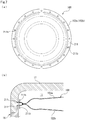
FIG. 3 is a bottom view illustrating a state where the metal diaphragm damper according to the first embodiment is attached between a housing and a housing cover. -
FIG. 4A is a cross-sectional view illustrating the structure of an outer peripheral portion of the metal diaphragm damper according to the first embodiment,FIG. 4B is a cross-sectional view taken along line A-A, andFIG. 4C is a cross-sectional view taken along line B-B. -
FIG. 5A is a cross-sectional view illustrating a state at the time of contraction of the diaphragms according to the first embodiment, andFIG. 5B is a cross-sectional view illustrating a state at the time of movement of a diaphragm of the first embodiment. -
FIG. 6A is a cross-sectional view illustrating a state where a metal diaphragm damper according to a second embodiment of the present invention is attached between a housing and a housing cover, andFIG. 6B is a cross-sectional view illustrating a state at the time of movement of a diaphragm of the second embodiment. -
FIG. 7A is a top view illustrating a metal diaphragm damper according to a third embodiment of the present invention, andFIG. 7B is a cross-sectional view illustrating a state where the metal diaphragm damper according to the third embodiment is attached between a housing and a housing cover. - Modes for implementing a metal diaphragm damper according to the present invention will be described below on the basis of embodiments.
- A structure for attaching a metal diaphragm damper according to a first embodiment of the present invention will be described with reference to
FIGS. 1 to 5 . - As illustrated in
FIG. 1 , ametal diaphragm damper 1 of the present embodiment is built in a high-pressure fuel pump 10 for pumping fuel, which is supplied from a fuel tank through a fuel inlet (not illustrated), to an injector. The high-pressure fuel pump 10 pressurizes and discharges fuel by the reciprocation of aplunger 12 that is driven by the rotation of a cam shaft (not illustrated) of an internal-combustion engine. - As a mechanism for pressurizing and discharging fuel in the high-
pressure fuel pump 10, an intake stroke for opening anintake valve 13 and taking in fuel to a pressurizingchamber 14 from afuel chamber 11 formed on a fuel inlet side, when theplunger 12 is moved down, is performed first. Then, an amount adjustment stroke for returning a part of the fuel of the pressurizingchamber 14 to thefuel chamber 11, when theplunger 12 is moved up, is performed, and a pressurization stroke for pressurizing fuel, when theplunger 12 is further moved up after theintake valve 13 is closed, is performed. As described above, the high-pressure fuel pump 10 repeats a cycle that includes the intake stroke, the amount adjustment stroke, and the pressurization stroke, to pressurize fuel, to open adischarge valve 15, and to discharge the fuel to the injector. In this case, pulsation in which high pressure and low pressure are repeated is generated in thefuel chamber 11 due to a change in the amount of fuel discharged to the injector from the high-pressure fuel pump 10 or a change in the amount of fuel injected from the injector. - The
metal diaphragm damper 1 of the present embodiment is used to reduce such pulsation that is generated in thefuel chamber 11 of the high-pressure fuel pump 10 (i.e., a space between the housing and the housing cover). Meanwhile, themetal diaphragm damper 1 is disposed to partition thefuel chamber 11 of the high-pressure fuel pump 10 into an upper space and a lower space. Thefuel chamber 11 is formed by a recessedportion 16a that is formed in ahousing 16 of the high-pressure fuel pump 10 to be recessed down and ahousing cover 17 that has a downward U-shaped cross-section and closes the recessedportion 16a. Outerperipheral portions metal diaphragm damper 1 are held between thehousing 16 and thehousing cover 17. - As illustrated in
FIGS. 2 and4 , anannular wall portion 16b, which is thinner than ahousing body portion 16A, is formed on the inner peripheral side of the upper edge of thehousing 16 to extend upward, and a steppedportion 16e is formed between thewall portion 16b and thehousing body portion 16A. The steppedportion 16e is formed by the outer peripheral surface of thewall portion 16b, ahorizontal surface 16f that extends toward an outer peripheral side so as to be perpendicular to thewall portion 16b, and the outer peripheral surface of thehousing body portion 16A that extends from the outer edge of thehorizontal surface 16f as to be perpendicular to thehorizontal surface 16f. Further,convex portions 16c extending upward are formed on thewall portion 16b so as to be spaced apart from each other at predetermined intervals in a circumferential direction. That is, aconcave portion 16d, which is formed by the side surfaces of theconvex portions 16c and the upper end face of thewall portion 16b, is formed between the adjacentconvex portions 16c. For the convenience of illustration, the lower structure of thehousing 16 is not illustrated inFIG. 2 . - A
tubular portion 17a to be externally fitted to thewall portion 16b is formed at the lower end portion of thehousing cover 17. In a state where thetubular portion 17a is externally fitted to thewall portion 16b, the lower end face of thetubular portion 17a is in contact with thehorizontal surface 16f of the steppedportion 16e and is positioned in a vertical direction. -
Convex portions 17b andconcave portions 17c are formed on the inner peripheral side of thetubular portion 17a. Theconvex portions 17b extend toward theconvex portions 16c so as to face theconvex portions 16c with a distance L1 (seeFIG. 4B ) interposed therebetween in the vertical direction in a state where thetubular portion 17a is externally fitted to thewall portion 16b, andconcave portions 17c are recessed toward the opposite side (i.e., upper side) so as to face theconcave portions 16d. As described above, theconvex portions metal diaphragm damper 1 in the vertical direction. The same applies to theconcave portions - That is, in a state where the
housing cover 17 is attached to thehousing 16, a distance L2 (seeFIG. 4C ) between theconcave portions convex portions FIG. 4B ) formed between theconvex portions FIG. 4C ) formed between theconcave portions housing 16 and thehousing cover 17, are recessed toward the outer peripheral side, and are continuous over the circumferential direction. Meanwhile, thehousing 16 and thehousing cover 17 are fixed to each other in a hermetically sealed state by laser welding. - As illustrated in
FIGS. 1 and2 , two disc-shapeddiaphragms metal diaphragm damper 1 is formed in the shape of a disc. - In detail, a welded portion W (see particularly
FIG. 4A ) is formed at the inner portions of thediaphragms peripheral portions notches peripheral portions notches like portions 21b (that is, remaining portions other than thenotches 21a) having the shape of a chevron in plan view are formed at the outerperipheral portions 21. Thediaphragms respective notches 21a and the respective plate-like portions 21b of thediaphragms peripheral portions 21 of the present embodiment mean the portions of thediaphragms - A hermetically sealed space S3 formed between the
diaphragms FIGS. 1 and4 )) is filled with gas that is formed of argon, helium, and the like and has predetermined pressure. Meanwhile, the amount of change in the volume of themetal diaphragm damper 1 is adjusted using the pressure of gas to be filled in the hermetically sealed space S3, so that preferable pulsation absorption performance can be obtained. - As illustrated in
FIGS. 3 and4 , each of thediaphragms peripheral portion 21, acurved portion 22, and a deformable-action portion 23 close to the central side (i.e., inner peripheral side) are formed at each of thediaphragms diaphragms housing 16 is present on the front side of the plane ofFIG. 3 . However, for the convenience of illustration, the components of thehousing 16 are not illustrated inFIG. 3 . - Particularly, as illustrated in
FIG. 4A , the plate-like portions peripheral portions diaphragms like portions FIG.4 . The same hereinafter.), as going toward the outside in a radial direction. Further, thecurved portions diaphragms curved portions curved portions curved portions action portions 23 are curved so as to be spaced apart from each other. Meanwhile, the firstcurved portions diaphragms - The deformable-
action portion 23 is a portion that is formed in a dome shape and is to be elastically deformed by differential pressure between external pressure and the pressure of gas to be filled in the hermetically sealed space S3. Meanwhile, the shape of the deformable-action portion 23 may be the shape of a single continuous curved surface, or may be a shape including a plurality of curved surfaces, for example, the shape of a corrugated plate in cross-sectional view. That is, the shape of the deformable-action portion 23 may be freely changed. - As illustrated in
FIGS. 3 and4B , the respective plate-like portions 21b of thediaphragms metal diaphragm damper 1 are held (in the gaps S1) between theconvex portions 16c of thehousing 16 and theconvex portions 17b of thehousing cover 17 in a thickness direction. - Specifically, in a state where the plate-
like portions peripheral portions convex portions FIG. 4A ), the outer edges of the outerperipheral portions like portions peripheral portions convex portions FIG. 4B ), the outer edges of the outerperipheral portions peripheral portions convex portions peripheral portions convex portions metal diaphragm damper 1 can be reliably attached without rattling regardless of the dimensional accuracy of thehousing 16 and thehousing cover 17. Further, since the outer diameter of themetal diaphragm damper 1 is smaller than the inner diameter of thetubular portion 17a, a gap is formed between themetal diaphragm damper 1 and thetubular portion 17a in the radial direction. - As illustrated in
FIGS. 3 and4C , a part of each of thenotches 21a of thediaphragms fuel chamber 11 in a state where themetal diaphragm damper 1 is attached between thehousing 16 and thehousing cover 17. For this reason, fuel present in thefuel chamber 11 can be moved to one side (i.e., lower side) and the other side (upper side) of themetal diaphragm damper 1 through therespective notches 21a. - Further, the
respective notches 21a communicate with the gaps S2 (i.e., communication grooves) formed between theconcave portions respective notches 21a and the gaps S2 function as communication passages that allow one side and the other side of themetal diaphragm damper 1 to communicate with each other, the cross-sectional area of the flow channels of the communication passages can be increased. Furthermore, since the gaps S1 and S2 are continuous over the circumferential direction, the cross-sectional area of the flow channels of the communication passages can be increased in comparison with a case where the gaps S1 and S2 are discontinuous in the circumferential direction. Moreover, since thenotches 21a are formed by notching of the outer edges of the outerperipheral portions peripheral portions - Next, an operation will be described. When fuel pressure accompanied by pulsation is changed to high pressure from low pressure and the
diaphragms fuel chamber 11, the deformable-action portions FIG. 5A . Meanwhile, since the deformable-action portions - When the deformable-
action portions diaphragms metal diaphragm damper 1 and thetubular portion 17a in the radial direction as described above, an increase in the diameters of thediaphragms curved portions curved portions curved portions curved portions curved portions - Since the outer
peripheral portions housing 16 and thehousing cover 17 as described above, thehousing 16 and thehousing cover 17 are not in contact with the deformable-action portions housing 16 and thehousing cover 17 do not inhibit the elastic deformation of the deformable-action portions housing 16 and thehousing cover 17 can be adapted not to affect a pulsation-reducing function. - Further, since the outer
peripheral portions diaphragms housing 16 and thehousing cover 17, a separate attachment member and the like do not need to be prepared. Accordingly, the number of parts can be reduced. That is, in the structure for attaching themetal diaphragm damper 1 according to the present embodiment, an excellent pulsation-reducing function can be achieved with a simple structure. Further, since thehousing 16 and thehousing cover 17 having high strength hold the outerperipheral portions metal diaphragm damper 1 can be reliably held in comparison with a case where themetal diaphragm damper 1 is held by the separate attachment member. - Further, when the
metal diaphragm damper 1 receives large pulsation accompanied by shock waves from one side (lower side) thereof as illustrated inFIG. 5B , thediaphragm damper 1 is adapted to reduce a force caused by the shock waves by being curved toward the other side (i.e., upper side) as a whole immediately afterwards. - Specifically, when portions of the
diaphragms metal diaphragm damper 1, as a whole, the outerperipheral portion 21 of thediaphragm 2a and the outerperipheral portion 21 of thediaphragm 2b are elastically deformed or start to move rotationally from the gap S1 substantially at the same time. Since fuel is present on the upper side of thecurved portion 22 and the deformable-action portion 23 of thediaphragm 2a, thecurved portion 22 and the deformable-action portion 23 of thediaphragm 2a are slightly bent upward. On the other hand, thecurved portion 22 and the deformable-action portion 23 of thediaphragm 2b are further pushed up and is deformed to be crushed toward the hermetically sealed space S3 (seeFIG. 5B ) . After that, when high pressure is transmitted to even thediaphragm 2a, thediaphragm 2a is also crushed toward the hermetically sealed space S3. As a result, thediaphragm damper 1 is deformed (seeFIG. 5A ) . - Since the welded portion W is provided closer to the inside than the outer
peripheral portions metal diaphragm damper 1 as described above, the portions of thediaphragms peripheral portions - Further, when the
metal diaphragm damper 1 receives large pulsation accompanied by shock waves and is moved to the other side from one side, the outerperipheral portion 21 of thediaphragm 2a and the outerperipheral portion 21 of thediaphragm 2b are separately elastically deformed or move rotationally and the outerperipheral portion 21 of thediaphragm 2a and the outerperipheral portion 21 of thediaphragm 2b are subjected to different deformation. Accordingly, stress can be distributed to different positions on the outerperipheral portions peripheral portions - Meanwhile, the portions of the
diaphragms pressure fuel pump 10 to which themetal diaphragm damper 1 is applied. - Next, a structure for attaching a metal diaphragm damper according to a second embodiment will be described with reference to
FIG. 6 . Meanwhile, the same components as those described in the embodiment will be denoted by the same reference numerals as those described in the embodiment, and the repeated description will be omitted. - Since a
convex portions 16c' of ahousing 16 and aconvex portions 17b' of ahousing cover 17 of the second embodiment are disposed close to each other in comparison with the first embodiment as illustrated inFIG. 6A , the outerperipheral portions metal diaphragm damper 1 are in contact with each other in the thickness direction in a state where the outerperipheral portions convex portions 16c' and theconvex portions 17b'. - As illustrated in
FIG. 6B , when the portions of thediaphragms peripheral portions convex portions 16c' and theconvex portions 17b'. That is, the outerperipheral portions peripheral portions peripheral portions diaphragms - Meanwhile, the edge portions of the outer
peripheral portions convex portions 16c' and theconvex portions 17b' may be formed thin so that the edge portions are easily deformed, or may be formed thick so that the strength of the edge portion is increased. - Next, a structure for attaching a metal diaphragm damper according to a third embodiment will be described with reference to
FIG. 7 . Meanwhile, the same components as those described in the embodiment will be denoted by the same reference numerals as those described in the embodiment, and the repeated description will be omitted. - As illustrated in
FIG. 7A , a plurality of through-hole 211b, which penetratesdiaphragms peripheral portions 211 of thediaphragms metal diaphragm damper 100 of the third embodiment to be spaced apart from each other in a circumferential direction. Since the respective through-holes 211b are disposed in thefuel chamber 11 in a state where themetal diaphragm damper 100 is attached between thehousing 16 and thehousing cover 17, fuel can be moved to one side and the other side of themetal diaphragm damper 100 through the respective through-holes 211b as illustrated inFIG. 7B . Meanwhile, the through-hole 211b is not limited to a circular shape in plan view, and may have, for example, an elliptical shape (or a slotted hole), a rectangular shape, or the like in plan view. - The embodiments of the present invention have been described above with reference to the drawings, but specific configuration is not limited to the embodiments. Even though modifications or additions are provided without departing from the scope of the present invention, the modifications or additions are included in the present invention.
- For example, the
diaphragms diaphragms diaphragms - Further, forms that include both the communication passages (the
notches 21a or the through-holes 211b) of the metal diaphragm damper and the communication passages (the gaps S1 and S2) of the housing and the housing cover have been exemplified in the first to third embodiments, but at least any one of the metal diaphragm damper or the housing and the housing cover may be provided with the communication passages. - The first
curved portions - Further, a restriction member for restricting excessive elastic deformation of the
diaphragms metal diaphragm damper 1. In this case, it is preferable that the restriction member has a shape allowing the appropriate volume change ratios of thediaphragms diaphragms diaphragms - Moreover, the
diaphragms curved portions 22 having an S-shaped cross-section and the dome-shaped deformable-action portions 23 have been described in the embodiments, but the shape of the diaphragm may be freely designed. For example, the diaphragm may have a shape that includes a deformable-action portion having a linear cross-section and a curved portion provided at the outer edge of the deformable-action portion and having a circular arc-shaped cross-section. -
- 1
- Metal diaphragm damper
- 2a, 2b
- Diaphragm
- 10
- High-pressure fuel pump
- 11
- Fuel chamber (space)
- 16
- Housing
- 16c, 16c'
- Convex portion
- 16d
- Concave portion
- 17
- Housing cover
- 17b, 17b'
- Convex portion
- 17c
- Concave portion
- 21
- Outer peripheral portion
- 21a
- Notch (communication passage)
- 22
- Curved portion
- 22a
- First curved portion (contact portion)
- 22b
- Second curved portion
- 23
- Deformable-action portion
- S1, S2
- Gap (communication passage, communication groove)
- S3
- Hermetically sealed space
- W
- Welded portion
Claims (8)
- A structure for attaching a metal diaphragm damper, comprising:a housing;a housing cover that cooperates with the housing to define a space between the housing and the housing cover; anda pair of diaphragms each formed in a disk shape, the pair of diaphragms having weld portions on an outer periphery side thereof, the weld portions being welded to each other in an annular shape to form the metal diaphragm damper of which inside is filled with gas, the metal diaphragm damper being attached to the housing and the housing cover so as to be disposed in the space between the housing and the housing cover,wherein the pair of diaphragms is provided with outer peripheral portions on the outer peripheral side of the welded portions, andthe outer peripheral portions of the pair of diaphragms are held by the housing and the housing cover in a thickness direction of the pair of diaphragms.
- The structure for attaching a metal diaphragm damper according to claim 1,
wherein the outer peripheral portions of the pair of diaphragms are formed to be opened in a direction where the outer peripheral portions are spaced apart from each other as going toward the outside in a radial direction. - The structure for attaching a metal diaphragm damper according to claim 1 or 2,
wherein the outer peripheral portions are provided with communication passages which allow both sides of the outer peripheral portions in a thickness direction thereof to communicate with each other. - The structure for attaching a metal diaphragm damper according to claim 3,
wherein the communication passages are formed by cutouts of outer edges of the outer peripheral portions. - The structure for attaching a metal diaphragm damper according to claim 3 or 4,
wherein communication grooves are formed over the housing and the housing cover. - The structure for attaching a metal diaphragm damper according to any one of claims 1 to 5,
wherein the pair of diaphragms is provided with curved portions which are formed on an inner peripheral side of the weld portions so as to be spaced apart from each other as going toward a radially inward side from base end portions inwardly continuous with the welded portions, the base end portions being brought into contact with each other. - The structure for attaching a metal diaphragm damper according to any one of claims 1 to 6,
wherein the outer peripheral portions of the pair of diaphragms are held by the housing and the housing cover in a state where the outer peripheral portions of the pair of diaphragms are spaced from each other. - The structure for attaching a metal diaphragm damper according to any one of claims 1 to 6,
wherein the outer peripheral portions of the pair of diaphragms are held by the housing and the housing cover in a state where the outer peripheral portions of the pair of diaphragms are in contact with each other.
Applications Claiming Priority (2)
| Application Number | Priority Date | Filing Date | Title |
|---|---|---|---|
| JP2018096188 | 2018-05-18 | ||
| PCT/JP2019/019616 WO2019221259A1 (en) | 2018-05-18 | 2019-05-17 | Structure for attaching metal diaphragm damper |
Publications (2)
| Publication Number | Publication Date |
|---|---|
| EP3795818A1 true EP3795818A1 (en) | 2021-03-24 |
| EP3795818A4 EP3795818A4 (en) | 2022-02-16 |
Family
ID=68539935
Family Applications (1)
| Application Number | Title | Priority Date | Filing Date |
|---|---|---|---|
| EP19803571.9A Withdrawn EP3795818A4 (en) | 2018-05-18 | 2019-05-17 | Structure for attaching metal diaphragm damper |
Country Status (6)
| Country | Link |
|---|---|
| US (1) | US11242832B2 (en) |
| EP (1) | EP3795818A4 (en) |
| JP (1) | JPWO2019221259A1 (en) |
| KR (1) | KR20200137010A (en) |
| CN (1) | CN111989477A (en) |
| WO (1) | WO2019221259A1 (en) |
Families Citing this family (4)
| Publication number | Priority date | Publication date | Assignee | Title |
|---|---|---|---|---|
| JP7074563B2 (en) * | 2018-05-18 | 2022-05-24 | イーグル工業株式会社 | Damper device |
| WO2019221261A1 (en) | 2018-05-18 | 2019-11-21 | イーグル工業株式会社 | Damper unit |
| CN111989479B (en) | 2018-05-18 | 2022-07-26 | 伊格尔工业股份有限公司 | shock absorber device |
| CN112055780A (en) | 2018-05-25 | 2020-12-08 | 伊格尔工业股份有限公司 | Shock absorber device |
Family Cites Families (48)
| Publication number | Priority date | Publication date | Assignee | Title |
|---|---|---|---|---|
| JPH10299609A (en) | 1997-04-18 | 1998-11-10 | Zexel Corp | Pulsation reducing damper |
| JP4036153B2 (en) | 2003-07-22 | 2008-01-23 | 株式会社日立製作所 | Damper mechanism and high-pressure fuel supply pump |
| WO2008086012A1 (en) | 2007-01-10 | 2008-07-17 | Stanadyne Corporation | Inlet pressure attenuator for single plunger fuel pump |
| JP4380724B2 (en) | 2007-04-16 | 2009-12-09 | 株式会社日立製作所 | Damper mechanism and high-pressure fuel supply pump |
| JP4380751B2 (en) * | 2007-09-11 | 2009-12-09 | 株式会社日立製作所 | Damper mechanism and high-pressure fuel supply pump |
| JP5002523B2 (en) | 2008-04-25 | 2012-08-15 | 日立オートモティブシステムズ株式会社 | Fuel pressure pulsation reduction mechanism and high-pressure fuel supply pump for internal combustion engine equipped with the same |
| DE102008043217A1 (en) | 2008-10-28 | 2010-04-29 | Robert Bosch Gmbh | High-pressure fuel pump for an internal combustion engine |
| JP4726262B2 (en) | 2009-02-13 | 2011-07-20 | 株式会社デンソー | Damper device and high-pressure pump using the same |
| JP4736142B2 (en) | 2009-02-18 | 2011-07-27 | 株式会社デンソー | High pressure pump |
| JP4678065B2 (en) | 2009-02-25 | 2011-04-27 | 株式会社デンソー | Damper device, high-pressure pump using the same, and manufacturing method thereof |
| JP5252076B2 (en) | 2009-03-17 | 2013-07-31 | トヨタ自動車株式会社 | Pulsation damper |
| IT1396143B1 (en) | 2009-11-03 | 2012-11-16 | Magneti Marelli Spa | FUEL PUMP WITH REDUCED WEAR ON A GASKET FOR A DIRECT INJECTION SYSTEM |
| IT1396142B1 (en) | 2009-11-03 | 2012-11-16 | Magneti Marelli Spa | FUEL PUMP WITH DAMPENER PERFECTED FOR A DIRECT INJECTION SYSTEM |
| JP5333937B2 (en) | 2009-11-09 | 2013-11-06 | 株式会社デンソー | High pressure pump |
| JP5136919B2 (en) | 2010-04-08 | 2013-02-06 | 株式会社デンソー | High pressure pump |
| US8727752B2 (en) | 2010-10-06 | 2014-05-20 | Stanadyne Corporation | Three element diaphragm damper for fuel pump |
| CN102619660B (en) | 2011-01-28 | 2015-06-24 | 株式会社电装 | High pressure pump |
| KR101199323B1 (en) | 2011-02-08 | 2012-11-09 | (주)모토닉 | High presure fuel pump for direct injection type gasoline engine |
| JP5644615B2 (en) | 2011-03-22 | 2014-12-24 | 株式会社デンソー | Pulsation damper and high-pressure pump equipped with the same |
| US9109593B2 (en) | 2011-08-23 | 2015-08-18 | Denso Corporation | High pressure pump |
| JP5628121B2 (en) * | 2011-09-20 | 2014-11-19 | 日立オートモティブシステムズ株式会社 | High pressure fuel supply pump |
| JP5569573B2 (en) | 2012-03-05 | 2014-08-13 | 株式会社デンソー | High pressure pump |
| JP5821769B2 (en) * | 2012-04-24 | 2015-11-24 | 株式会社デンソー | Damper device |
| JP6066483B2 (en) | 2013-03-26 | 2017-01-25 | マルヤス工業株式会社 | Fuel pressure pulsation reduction device |
| US20150017040A1 (en) | 2013-07-12 | 2015-01-15 | Denso Corporation | Pulsation damper and high-pressure pump having the same |
| JP5979092B2 (en) | 2013-07-23 | 2016-08-24 | トヨタ自動車株式会社 | Pulsation damper and high-pressure fuel pump |
| DE102013219428A1 (en) | 2013-09-26 | 2015-03-26 | Continental Automotive Gmbh | Damper for a high-pressure pump |
| JP5907145B2 (en) | 2013-11-12 | 2016-04-20 | 株式会社デンソー | High pressure pump |
| JP2015232283A (en) | 2014-06-09 | 2015-12-24 | トヨタ自動車株式会社 | Damper device |
| KR20160121010A (en) * | 2015-04-09 | 2016-10-19 | 주식회사 현대케피코 | Damper assembly of high-pressure fuelpump |
| JP6413017B2 (en) | 2015-05-27 | 2018-10-24 | 株式会社不二工機 | Pulsation damper |
| EP3330564B1 (en) | 2015-07-31 | 2020-03-25 | Eagle Industry Co., Ltd. | Diaphragm damper |
| EP3330563B1 (en) | 2015-07-31 | 2021-03-03 | Eagle Industry Co., Ltd. | Diaphragm damper device coiled wave spring and damper system |
| JP6434871B2 (en) | 2015-07-31 | 2018-12-05 | トヨタ自動車株式会社 | Damper device |
| WO2017022604A1 (en) * | 2015-07-31 | 2017-02-09 | イーグル工業株式会社 | Diaphragm damper device, holding member therefor, and production method for diaphragm damper device |
| DE102015219537A1 (en) | 2015-10-08 | 2017-04-27 | Robert Bosch Gmbh | Diaphragm can for damping pressure pulsations in a low-pressure region of a piston pump |
| DE102015223159A1 (en) | 2015-11-24 | 2017-06-08 | Robert Bosch Gmbh | Fuel injection system with a diaphragm damper |
| DE102016200125B4 (en) * | 2016-01-08 | 2018-05-30 | Continental Automotive Gmbh | High-pressure fuel pump |
| DE102016203217B4 (en) * | 2016-02-29 | 2020-12-10 | Vitesco Technologies GmbH | Damper capsule, pressure pulsation damper and high-pressure fuel pump |
| DE102016205428A1 (en) | 2016-04-01 | 2017-10-05 | Robert Bosch Gmbh | Pressure damping device for a fluid pump, in particular for a high pressure pump of a fuel injection system |
| WO2018056109A1 (en) * | 2016-09-26 | 2018-03-29 | イーグル工業株式会社 | Metal diaphragm damper |
| JP6869005B2 (en) * | 2016-10-31 | 2021-05-12 | 日立Astemo株式会社 | Fuel supply pump |
| JP6919314B2 (en) | 2017-05-11 | 2021-08-18 | 株式会社デンソー | Pulsation damper and fuel pump device |
| DE102017213891B3 (en) | 2017-08-09 | 2019-02-14 | Continental Automotive Gmbh | High-pressure fuel pump for a fuel injection system |
| WO2019178349A1 (en) | 2018-03-14 | 2019-09-19 | Nostrum Energy Pte. Ltd. | Pump for internal combustion engine and method of forming the same |
| WO2019221261A1 (en) | 2018-05-18 | 2019-11-21 | イーグル工業株式会社 | Damper unit |
| CN111989479B (en) | 2018-05-18 | 2022-07-26 | 伊格尔工业股份有限公司 | shock absorber device |
| JP2021110312A (en) | 2020-01-15 | 2021-08-02 | 株式会社デンソー | Manufacturing method of assembly, part set, manufacturing method of fuel injection pump, and fuel injection pump |
-
2019
- 2019-05-17 JP JP2020519934A patent/JPWO2019221259A1/en active Pending
- 2019-05-17 WO PCT/JP2019/019616 patent/WO2019221259A1/en not_active Ceased
- 2019-05-17 EP EP19803571.9A patent/EP3795818A4/en not_active Withdrawn
- 2019-05-17 CN CN201980026782.7A patent/CN111989477A/en active Pending
- 2019-05-17 US US17/048,992 patent/US11242832B2/en active Active
- 2019-05-17 KR KR1020207032120A patent/KR20200137010A/en not_active Ceased
Also Published As
| Publication number | Publication date |
|---|---|
| JPWO2019221259A1 (en) | 2021-06-10 |
| US20210246860A1 (en) | 2021-08-12 |
| EP3795818A4 (en) | 2022-02-16 |
| KR20200137010A (en) | 2020-12-08 |
| US11242832B2 (en) | 2022-02-08 |
| WO2019221259A1 (en) | 2019-11-21 |
| CN111989477A (en) | 2020-11-24 |
Similar Documents
| Publication | Publication Date | Title |
|---|---|---|
| US11242832B2 (en) | Structure for attaching metal diaphragm damper | |
| EP1995446B1 (en) | Fluid pressure pulsation damper mechanism and high-pressure fuel pump equipped with fluid pressure pulsation damper mechanism | |
| EP3816430B1 (en) | Damper unit | |
| EP3816429B1 (en) | Damper device | |
| US10480704B2 (en) | Pulsation damper | |
| US20200290554A1 (en) | Gas generator | |
| JP2018189073A (en) | Pulsation damper and fuel pump device | |
| EP3517770B1 (en) | Metal diaphragm damper | |
| JP5402004B2 (en) | Pulsation damper | |
| US11181220B2 (en) | Metal diaphragm damper and manufacturing method for the same | |
| US11326568B2 (en) | Damper device | |
| JP2001027188A (en) | Scroll fluid machine | |
| CN112055781B (en) | Shock absorber device | |
| WO2019102982A1 (en) | Metal diaphragm damper |
Legal Events
| Date | Code | Title | Description |
|---|---|---|---|
| STAA | Information on the status of an ep patent application or granted ep patent |
Free format text: STATUS: THE INTERNATIONAL PUBLICATION HAS BEEN MADE |
|
| PUAI | Public reference made under article 153(3) epc to a published international application that has entered the european phase |
Free format text: ORIGINAL CODE: 0009012 |
|
| STAA | Information on the status of an ep patent application or granted ep patent |
Free format text: STATUS: REQUEST FOR EXAMINATION WAS MADE |
|
| 17P | Request for examination filed |
Effective date: 20201201 |
|
| AK | Designated contracting states |
Kind code of ref document: A1 Designated state(s): AL AT BE BG CH CY CZ DE DK EE ES FI FR GB GR HR HU IE IS IT LI LT LU LV MC MK MT NL NO PL PT RO RS SE SI SK SM TR |
|
| AX | Request for extension of the european patent |
Extension state: BA ME |
|
| DAV | Request for validation of the european patent (deleted) | ||
| DAX | Request for extension of the european patent (deleted) | ||
| A4 | Supplementary search report drawn up and despatched |
Effective date: 20220119 |
|
| RIC1 | Information provided on ipc code assigned before grant |
Ipc: F02M 59/44 20060101ALI20220113BHEP Ipc: F02M 55/02 20060101ALI20220113BHEP Ipc: F02M 55/00 20060101AFI20220113BHEP |
|
| STAA | Information on the status of an ep patent application or granted ep patent |
Free format text: STATUS: THE APPLICATION IS DEEMED TO BE WITHDRAWN |
|
| 18D | Application deemed to be withdrawn |
Effective date: 20220819 |