EP3795808B1 - Steam and gas turbine device - Google Patents
Steam and gas turbine device Download PDFInfo
- Publication number
- EP3795808B1 EP3795808B1 EP20205484.7A EP20205484A EP3795808B1 EP 3795808 B1 EP3795808 B1 EP 3795808B1 EP 20205484 A EP20205484 A EP 20205484A EP 3795808 B1 EP3795808 B1 EP 3795808B1
- Authority
- EP
- European Patent Office
- Prior art keywords
- steam
- gas turbine
- gas
- heater
- heat
- Prior art date
- Legal status (The legal status is an assumption and is not a legal conclusion. Google has not performed a legal analysis and makes no representation as to the accuracy of the status listed.)
- Active
Links
Images


Classifications
-
- F—MECHANICAL ENGINEERING; LIGHTING; HEATING; WEAPONS; BLASTING
- F01—MACHINES OR ENGINES IN GENERAL; ENGINE PLANTS IN GENERAL; STEAM ENGINES
- F01K—STEAM ENGINE PLANTS; STEAM ACCUMULATORS; ENGINE PLANTS NOT OTHERWISE PROVIDED FOR; ENGINES USING SPECIAL WORKING FLUIDS OR CYCLES
- F01K23/00—Plants characterised by more than one engine delivering power external to the plant, the engines being driven by different fluids
- F01K23/02—Plants characterised by more than one engine delivering power external to the plant, the engines being driven by different fluids the engine cycles being thermally coupled
- F01K23/06—Plants characterised by more than one engine delivering power external to the plant, the engines being driven by different fluids the engine cycles being thermally coupled combustion heat from one cycle heating the fluid in another cycle
- F01K23/10—Plants characterised by more than one engine delivering power external to the plant, the engines being driven by different fluids the engine cycles being thermally coupled combustion heat from one cycle heating the fluid in another cycle with exhaust fluid of one cycle heating the fluid in another cycle
-
- F—MECHANICAL ENGINEERING; LIGHTING; HEATING; WEAPONS; BLASTING
- F01—MACHINES OR ENGINES IN GENERAL; ENGINE PLANTS IN GENERAL; STEAM ENGINES
- F01K—STEAM ENGINE PLANTS; STEAM ACCUMULATORS; ENGINE PLANTS NOT OTHERWISE PROVIDED FOR; ENGINES USING SPECIAL WORKING FLUIDS OR CYCLES
- F01K13/00—General layout or general methods of operation of complete plants
- F01K13/02—Controlling, e.g. stopping or starting
-
- F—MECHANICAL ENGINEERING; LIGHTING; HEATING; WEAPONS; BLASTING
- F01—MACHINES OR ENGINES IN GENERAL; ENGINE PLANTS IN GENERAL; STEAM ENGINES
- F01K—STEAM ENGINE PLANTS; STEAM ACCUMULATORS; ENGINE PLANTS NOT OTHERWISE PROVIDED FOR; ENGINES USING SPECIAL WORKING FLUIDS OR CYCLES
- F01K23/00—Plants characterised by more than one engine delivering power external to the plant, the engines being driven by different fluids
- F01K23/12—Plants characterised by more than one engine delivering power external to the plant, the engines being driven by different fluids the engines being mechanically coupled
- F01K23/16—Plants characterised by more than one engine delivering power external to the plant, the engines being driven by different fluids the engines being mechanically coupled all the engines being turbines
-
- F—MECHANICAL ENGINEERING; LIGHTING; HEATING; WEAPONS; BLASTING
- F02—COMBUSTION ENGINES; HOT-GAS OR COMBUSTION-PRODUCT ENGINE PLANTS
- F02C—GAS-TURBINE PLANTS; AIR INTAKES FOR JET-PROPULSION PLANTS; CONTROLLING FUEL SUPPLY IN AIR-BREATHING JET-PROPULSION PLANTS
- F02C6/00—Plural gas-turbine plants; Combinations of gas-turbine plants with other apparatus; Adaptations of gas-turbine plants for special use
- F02C6/18—Plural gas-turbine plants; Combinations of gas-turbine plants with other apparatus; Adaptations of gas-turbine plants for special use using the waste heat of gas-turbine plants outside the plants themselves, e.g. gas-turbine power heat plants
-
- F—MECHANICAL ENGINEERING; LIGHTING; HEATING; WEAPONS; BLASTING
- F05—INDEXING SCHEMES RELATING TO ENGINES OR PUMPS IN VARIOUS SUBCLASSES OF CLASSES F01-F04
- F05D—INDEXING SCHEME FOR ASPECTS RELATING TO NON-POSITIVE-DISPLACEMENT MACHINES OR ENGINES, GAS-TURBINES OR JET-PROPULSION PLANTS
- F05D2220/00—Application
- F05D2220/30—Application in turbines
- F05D2220/31—Application in turbines in steam turbines
-
- F—MECHANICAL ENGINEERING; LIGHTING; HEATING; WEAPONS; BLASTING
- F05—INDEXING SCHEMES RELATING TO ENGINES OR PUMPS IN VARIOUS SUBCLASSES OF CLASSES F01-F04
- F05D—INDEXING SCHEME FOR ASPECTS RELATING TO NON-POSITIVE-DISPLACEMENT MACHINES OR ENGINES, GAS-TURBINES OR JET-PROPULSION PLANTS
- F05D2220/00—Application
- F05D2220/30—Application in turbines
- F05D2220/32—Application in turbines in gas turbines
Definitions
- the invention relates to a steam and gas turbine device as outlined in the introduction of Claim 1.
- Such steam and gas turbine device comprises, amongst others, at least a gas turbine unit (A) and a steam turbine unit (B), wherein the gas turbine unit (A) is partly composed of at least the following: a gas compressor positioned on a compressor axle, a combustion chamber and a gas turbine positioned on a gas turbine axle; and wherein the steam turbine unit (B) is partly composed of the following: a closed steam line in which at least the following are accommodated: a pump; a steam converter, which, in operation, is in heat-exchanging contact with the gases coming from the gas turbine; a steam turbine positioned on a steam turbine axle; as well as a condenser.
- a steam and gas turbine device according to the introduction of Claim 1 is disclosed, for example, in German patent publication no. DE102010033659 , or British patent publication no. GB671702 or in Japanese patent publication no. JP-H-0874517 .
- the object of the present invention is to provide a steam and gas turbine device according to the abovementioned introduction which does not have the drawbacks associated with the multi-axle and single-axis variant. More particularly, it is an object of the invention to provide a steam and gas turbine device of simple construction and without all kinds of complicated additional components.
- the steam and gas turbine device is characterized by the fact that the device comprises an air pre-heater, which brings the gases coming from the gas turbine into heat-exchanging contact with the gases coming from the gas compressor.
- the device comprises an air pre-heater, which brings the gases coming from the gas turbine into heat-exchanging contact with the gases coming from the gas compressor.
- it is possible to achieve an improved efficiency of the device via heat transfer from the gases coming from the gas turbine (having a high temperature) to the gases coming from the gas compressor (having a lower temperature).
- the steam converter comprises a steam generator, which, in operation, is in heat-exchanging contact with the combustible flue gases coming from the combustion chamber (2).
- the device furthermore comprises a further air pre-heater, which brings the steam line into heat-exchanging contact with the gases coming from the gas compressor.
- a further air pre-heater brings the steam line into heat-exchanging contact with the gases coming from the gas compressor.
- the further air pre-heater may be accommodated in the device downstream viewed from the steam generator and upstream viewed from the at least one heat exchanger. More specifically, the further air pre-heater is accommodated in the device downstream viewed from the steam turbine. This has the advantage that the steam in the steam line is first passed through the steam turbine at a high temperature, which improves the transfer of power to the steam turbine axle.
- the air pre-heater is accommodated in the device upstream viewed from the at least one heat exchanger and, more specifically, the air pre-heater is accommodated in the device downstream viewed from the further air pre-heater.
- the steam converter may comprise a steam superheater, which, in operation, is in heat-exchanging contact with the gases coming from the gas turbine.
- a steam superheater which, in operation, is in heat-exchanging contact with the gases coming from the gas turbine.
- the gas turbine is in flow connection with the combustion chamber in order to pass the gases coming from the gas turbine to the combustion chamber.
- the steam turbine and gas compressor are positioned on the same axle.
- the gas turbine unit (A) comprises a blow-off valve which is arranged upstream of the at least one heat exchanger for blowing off the gases coming from the gas compressor in a controlled manner.
- the blow-off valve may be accommodated in the gas turbine unit (A) downstream viewed from the further air pre-heater or in the gas turbine unit (A) upstream viewed from the air pre-heater or in the gas turbine unit (A) upstream viewed from the gas turbine.
- the compressor may consist of several compressors situated parallel to each other and/or in series and the turbine may consist of several turbines situated parallel to each other and/or in series and the steam turbine may consist of several steam turbines situated parallel to each other and/or in series.
- the efficiency of the steam turbine unit may furthermore be improved by the fact that, with a specific embodiment according to the invention, in operation, the water flowing through the steam line is in heat-exchanging contact with the air flowing through the intermediate cooler downstream of the condenser. More particularly, the heat-exchanging contact takes place according to the co-current principle or according to the countercurrent principle.
- the steam turbines may be impulse steam turbines or radial steam turbines
- the gas compressors may be centrifugal gas compressors or axial gas compressors
- the steam generator may be a once-through waste heat boiler.
- FIG. 1a-1b-2-3-4-5-6-7-8-9 successively show various embodiments of a steam and gas turbine device according to the invention.
- the gas compressor 1 is shown as being positioned on one axle 4, 10, together with the steam turbine 9.
- the power generated by the steam turbine unit (B) is transferred to the gas turbine 3 via the axle 4, 10 and the gas compressor 1, so that all of the power generated by this device is transferred to one axle 5 in order to drive the load 12.
- the steam turbines may be impulse steam turbines or radial steam turbines
- the gas compressors may be centrifugal gas compressors or axial gas compressors
- the steam generator may be a once-through waste heat boiler.
- the characteristic feature of the steam and gas turbine device is the mechanical disengagement of the gas compressor 1 and the gas turbine 3 which are not positioned on the same axle, but are positioned on different axles 4 and 5, respectively. This mechanical disengagement of the gas compressor 1 and the gas turbine 3 renders the use of additional, complicated coupling mechanisms obsolete.
- reference numeral 2 denotes an arbitrary combustion chamber/oven which is fed with fuel which is supplied via the inlet 2a.
- the combustion chamber/oven 2 may be used for any factory process which has a hot (waste) stream as output.
- the combustion chamber 2 may be of any desired design and may be, for example, a combustion engine or an incinerator, depending on the technical installation which is used in the steam and gas device according to the invention.
- Reference numeral 20 denotes a heat exchanger which brings the hot (waste) stream coming from the combustion chamber 2, such as combustible flue gases, into heat-exchanging contact with the gases coming from the gas compressor in compressed form via the outlet 1b.
- the heated gases leave the gas turbine 3 via the outlet 3b and are passed to the steam generator 8.
- the combustible flue gases are passed from the heat exchanger 20 through the steam generator 8 via the outlet 2b.
- the hot gas turbine gases and the hot combustible flue gases are brought into heat-exchanging contact with the water flowing through the closed steam line 6, so that steam is generated, by means of which the steam turbine 9 is driven.
- the gas compressor 1 is positioned on one axle 4, 10 together with the steam turbine 9.
- the power generated by the steam turbine unit (B) is transferred to the gas turbine 3 via the axle 4, 10 and the gas compressor 1, so that all the power generated by this device is transferred to one axle 5 in order to drive the load 12.
- the entire unit can easily be coupled to installations which already contain a combustion unit.
- the steam and gas turbine device requires few modifications as the heat exchanger 20 can easily be connected to the hot (waste) stream outlet of the combustion chamber 2 which is already present.
- the steam converter comprises a steam generator 8 which, in operation, brings the steam/water line 6 into heat-exchanging contact with the combustible flue gases coming from the heat exchanger 20 via the outlet 2b and also with the gases coming from the gas turbine 3 via the outlet 3b.
- FIG. 2 One other more efficient embodiment of the steam and gas turbine device is illustrated in Fig. 2 , wherein the reference numeral 30 comprises a first air pre-heater which brings the steam line 6 through which the compressed gases coming from the gas compressor 1 pass into heat-exchanging contact with the outlet 1b.
- the waste heat of the steam passed through the steam/water line 6 is emitted to the gases compressed by the gas compressor 1 and flowing through the outlet 1b, so that these gases are passed to the heat exchanger 20 in preheated and compressed form via the outlet 1b.
- the first air pre-heater 30 is accommodated in the device downstream viewed from the steam generator 8 and upstream viewed from the heat exchanger 20. More specifically, as is illustrated in Fig. 2 , the first air pre-heater 30 brings the outlet 1b of the gas compressor into heat-exchanging contact with the steam/water line 6 downstream viewed from the steam turbine 9.
- FIG. 3 a particular form of the embodiment of the steam and gas turbine device according to the invention shown in Fig. 2 is illustrated.
- reference numeral 40 denotes a second air pre-heater which brings the gases coming from the gas turbine 3 into heat-exchanging contact with the gases coming from the gas compressor 1 and more particularly the gases coming from the first air pre-heater 30.
- the gases coming from the gas turbine 3 are passed to the steam converter/steam generator 8 (see outlet 3b) after they have passed through the second air pre-heater 40.
- An improved energy efficiency is achieved in this case as well in the form of heat recovery, due to the fact that the compressed gases which are released from the gas compressor 1 via the outlet 1b are preheated due to the transfer of energy from the gases from the gas turbine 3.
- Fig. 4 is derived from the embodiment from Fig. 1 , albeit that the steam converter also comprises a steam superheater 50 in addition to a steam generator 8, so that, in operation, the steam/water line 6 is in heat-exchanging contact with the gases coming from the gas turbine 3. In this embodiment, these gases are blown off via the outlet 3b.
- an additional water spray injector may be provided with this steam superheater 50 in order to introduce a water mist into the steam/water line 6, so that extra steam is generated which can be passed to the steam turbine 9.
- FIG. 5 A combination of the embodiments from Figs. 2 and 4 is illustrated in Fig. 5 .
- both a first air pre-heater 30 and a steam superheater 50 are implemented in which the gases coming from the gas turbine 3 are blown off via the outlet 3b.
- the steam conversion in the steam generator 8 only takes place by heat transfer between the combustible flue gases (outlet 2b) coming from the combustion chamber 2 and the heat exchanger 20 and the water passed to the steam generator 8 via the pump 7.
- Fig. 6 which refers back to the embodiment according to Fig. 1 in which the gases coming from the gas turbine 3 are not first passed to the steam converter 8, but are first passed to the combustion chamber 2, where they are fed to the combustion process.
- the gases fed to the combustion chamber 2 via the gas turbine 3 are also passed through the steam generator 8 as combustible flue gases via the outlet 2b.
- the steam generator is thus only supplied with combustible flue gases via the outlet 2b which are composed of gases which are passed to the combustion chamber 2 via the inlet 2a or via the outlet 3b of the gas turbine 3.
- FIG. 7 A combination of the embodiments from Figs. 2 and 6 is illustrated in Fig. 7 . Also in this embodiment, the gases coming from the gas turbine 3 are passed to the combustion chamber 2 via the outlet 3b and the steam/water line 6 is in heat-exchanging contact with the outlet 1b downstream viewed from the steam turbine 9, through which the compressed gases coming from the gas compressor 1 are passed.
- FIG. 8 A combination of the embodiments from Figs. 2 , 5 and 6 is illustrated in Fig. 8 .
- the steam superheater 50 is implemented which is in heat-exchanging contact with the gases coming from the gas turbine 3 which are passed into the combustion chamber 2 via the outlet 3b and of which only the combustible flue gases then come into heat-exchanging contact with the steam/water line 6 in the steam generator 8.
- the steam passed from the steam generator 8 to the steam superheater 50 is, in the first air pre-heater 30, again brought into heat-exchanging contact with the compressed gases which leave the gas compressor 1 via the outlet 1b.
- the heat-exchanging contact in the first and second air pre-heaters 30 and 40, respectively, between the compressed gases from the gas compressor 1 and the steam in the steam/water line 6, or in the steam generator 8 and the steam superheater 50, respectively, between the steam in the steam/water line 6 and the gases coming from the gas turbine 3 / the combustible flue gases coming from the heat exchanger 20 can take place according to the co-current principle or according to the countercurrent principle.
- reference numeral 21 denotes a blow-off valve which, is arranged in any case in all embodiments upstream of the gas turbine 3 (see all figures and in particular Fig. 1a ) and preferably upstream of the at least one heat exchanger 20 (see all figures and in particular Figs. 1b and 9 ) and serves for blowing off gases coming from the gas compressor 1 via the outlet 1c.
- the blow-off valve 21 is accommodated in the gas turbine unit (A) downstream viewed from the first air pre-heater 30 ( Figs.
- the device may comprise a blow-off valve 21 which is arranged upstream of the gas turbine 3 in order to blow off the gases coming from the gas compressor 1.
- the illustrated variants may be supplemented with an additional advantageous aspect, in which the blow-off valve 21 and the outlet 1c are in flow connection with the combustion chamber 2.
- the blow-off valve 21 is returned to the combustion chamber 2 via the outlet 1c.
- the gases coming from the gas compressor 1 and which are usually blown off via the blow-off valve 21 and the outlet 1c, are now returned to the combustion chamber 2.
- FIG. 9 shows an embodiment in which the combustion chamber 2 and the heat exchanger 20 have been integrated with each other such that they form a single entity, resulting in a more efficient energy conversion.
- the integration of the combustion chamber 2 and the heat exchanger 20 with each other to form a single entity may also be used in the other embodiments which are illustrated in Figs. 1a-1b-2-3-4-5-6-7-8 .
Landscapes
- Engineering & Computer Science (AREA)
- Chemical & Material Sciences (AREA)
- Combustion & Propulsion (AREA)
- Mechanical Engineering (AREA)
- General Engineering & Computer Science (AREA)
- Engine Equipment That Uses Special Cycles (AREA)
Description
- The invention relates to a steam and gas turbine device as outlined in the introduction of Claim 1. Such steam and gas turbine device comprises, amongst others, at least a gas turbine unit (A) and a steam turbine unit (B), wherein the gas turbine unit (A) is partly composed of at least the following: a gas compressor positioned on a compressor axle, a combustion chamber and a gas turbine positioned on a gas turbine axle; and wherein the steam turbine unit (B) is partly composed of the following: a closed steam line in which at least the following are accommodated: a pump; a steam converter, which, in operation, is in heat-exchanging contact with the gases coming from the gas turbine; a steam turbine positioned on a steam turbine axle; as well as a condenser.
- Steam and gas turbine devices are well known and are used industrially in all kinds of different configurations. An example of a steam and gas turbine device according to the abovementioned introduction is disclosed, for example, in
Netherlands patent no. 1028373C1 - The abovementioned known variants of known steam and gas turbine devices are relatively complicated devices with a number of constructional drawbacks and limitations with regard to transferring the power generated to a load, as a result of which the overall efficiency of such installations is also limited.
- A steam and gas turbine device according to the introduction of Claim 1 is disclosed, for example, in German patent publication no.
DE102010033659 , or British patent publication no.GB671702 JP-H-0874517 - The object of the present invention is to provide a steam and gas turbine device according to the abovementioned introduction which does not have the drawbacks associated with the multi-axle and single-axis variant. More particularly, it is an object of the invention to provide a steam and gas turbine device of simple construction and without all kinds of complicated additional components.
- According to the invention, the steam and gas turbine device according to the invention is characterized by the fact that the device comprises an air pre-heater, which brings the gases coming from the gas turbine into heat-exchanging contact with the gases coming from the gas compressor. In this case as well, it is possible to achieve an improved efficiency of the device via heat transfer from the gases coming from the gas turbine (having a high temperature) to the gases coming from the gas compressor (having a lower temperature).
- More particularly, the steam converter comprises a steam generator, which, in operation, is in heat-exchanging contact with the combustible flue gases coming from the combustion chamber (2).
- With a further functional embodiment, the device furthermore comprises a further air pre-heater, which brings the steam line into heat-exchanging contact with the gases coming from the gas compressor. As a result thereof, the compressed gases coming from the gas compressor are pre-heated by the steam in the steam line, which significantly improves the efficiency of the heat exchanger and the gas turbine.
- In this case, the further air pre-heater may be accommodated in the device downstream viewed from the steam generator and upstream viewed from the at least one heat exchanger. More specifically, the further air pre-heater is accommodated in the device downstream viewed from the steam turbine. This has the advantage that the steam in the steam line is first passed through the steam turbine at a high temperature, which improves the transfer of power to the steam turbine axle.
- In a further embodiment as outlined in Claim 1, the air pre-heater is accommodated in the device upstream viewed from the at least one heat exchanger and, more specifically, the air pre-heater is accommodated in the device downstream viewed from the further air pre-heater.
- Furthermore, the steam converter may comprise a steam superheater, which, in operation, is in heat-exchanging contact with the gases coming from the gas turbine. In this case, it is also possible to achieve a further heating of the steam in the steam line before passing this steam through the steam turbine. Also as a result thereof, the efficiency of the device is improved.
- More specifically, the gas turbine is in flow connection with the combustion chamber in order to pass the gases coming from the gas turbine to the combustion chamber.
- More particularly, the steam turbine and gas compressor are positioned on the same axle.
- Furthermore, the gas turbine unit (A) comprises a blow-off valve which is arranged upstream of the at least one heat exchanger for blowing off the gases coming from the gas compressor in a controlled manner.
- In this case, the blow-off valve may be accommodated in the gas turbine unit (A) downstream viewed from the further air pre-heater or in the gas turbine unit (A) upstream viewed from the air pre-heater or in the gas turbine unit (A) upstream viewed from the gas turbine.
- Furthermore, the compressor may consist of several compressors situated parallel to each other and/or in series and the turbine may consist of several turbines situated parallel to each other and/or in series and the steam turbine may consist of several steam turbines situated parallel to each other and/or in series.
- The efficiency of the steam turbine unit may furthermore be improved by the fact that, with a specific embodiment according to the invention, in operation, the water flowing through the steam line is in heat-exchanging contact with the air flowing through the intermediate cooler downstream of the condenser. More particularly, the heat-exchanging contact takes place according to the co-current principle or according to the countercurrent principle.
- With other embodiments of the steam and gas turbine device according to the invention, the steam turbines may be impulse steam turbines or radial steam turbines, the gas compressors may be centrifugal gas compressors or axial gas compressors and the steam generator may be a once-through waste heat boiler.
- The invention will now be explained with reference to a drawing, in which:
Figs. 1a-1b-2-3-4-5-6-7-8-9 successively show various embodiments of a steam and gas turbine device according to the invention. - In order to aid the understanding of the invention, similar components illustrated in the various figures will be denoted by the same reference numerals in the following description of the figures.
- In the embodiments of a steam and gas turbine device according to the invention illustrated in
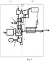
Fig. 1a and1b , the gas compressor 1 is shown as being positioned on oneaxle steam turbine 9. By means of this configuration of a steam and gas turbine device according to the invention, the power generated by the steam turbine unit (B) is transferred to thegas turbine 3 via theaxle axle 5 in order to drive theload 12. - With all the embodiments of the steam and gas turbine device according to the invention described here, the steam turbines may be impulse steam turbines or radial steam turbines, the gas compressors may be centrifugal gas compressors or axial gas compressors and the steam generator may be a once-through waste heat boiler.
- The characteristic feature of the steam and gas turbine device is the mechanical disengagement of the gas compressor 1 and the
gas turbine 3 which are not positioned on the same axle, but are positioned ondifferent axles gas turbine 3 renders the use of additional, complicated coupling mechanisms obsolete. - In this embodiment,
reference numeral 2 denotes an arbitrary combustion chamber/oven which is fed with fuel which is supplied via theinlet 2a. Actually, the combustion chamber/oven 2 may be used for any factory process which has a hot (waste) stream as output. Thecombustion chamber 2 may be of any desired design and may be, for example, a combustion engine or an incinerator, depending on the technical installation which is used in the steam and gas device according to the invention. -
Reference numeral 20 denotes a heat exchanger which brings the hot (waste) stream coming from thecombustion chamber 2, such as combustible flue gases, into heat-exchanging contact with the gases coming from the gas compressor in compressed form via theoutlet 1b. - Following the heat-exchanging contact between the combustible flue gases coming from the
combustion chamber 2 and the compressed gases coming from the gas compressor 1, the latter gases are passed into thegas turbine 3 via theinlet 3a. The compressed gases which have been heated by the heat-exchanging contact in theheat exchanger 10 drive thegas turbine 3, as a result of which the latter will start to rotate, together with thegas turbine axle 5, and will thus drive a load, which is denoted byreference numeral 12 in the figure. - The heated gases leave the
gas turbine 3 via theoutlet 3b and are passed to thesteam generator 8. Similarly, the combustible flue gases are passed from theheat exchanger 20 through thesteam generator 8 via theoutlet 2b. - In the
steam generator 8, the hot gas turbine gases and the hot combustible flue gases are brought into heat-exchanging contact with the water flowing through the closedsteam line 6, so that steam is generated, by means of which thesteam turbine 9 is driven. - In this steam and gas turbine device, the gas compressor 1 is positioned on one
axle steam turbine 9. Using this configuration, the power generated by the steam turbine unit (B) is transferred to thegas turbine 3 via theaxle axle 5 in order to drive theload 12. - By using the
heat exchanger 20 in this embodiment of the steam and gas turbine device according to the invention, the entire unit can easily be coupled to installations which already contain a combustion unit. As a result thereof, the steam and gas turbine device requires few modifications as theheat exchanger 20 can easily be connected to the hot (waste) stream outlet of thecombustion chamber 2 which is already present. - In the embodiment as illustrated in
Figs. 1a and1b , the steam converter comprises asteam generator 8 which, in operation, brings the steam/water line 6 into heat-exchanging contact with the combustible flue gases coming from theheat exchanger 20 via theoutlet 2b and also with the gases coming from thegas turbine 3 via theoutlet 3b. - One other more efficient embodiment of the steam and gas turbine device is illustrated in
Fig. 2 , wherein thereference numeral 30 comprises a first air pre-heater which brings thesteam line 6 through which the compressed gases coming from the gas compressor 1 pass into heat-exchanging contact with theoutlet 1b. Here, the waste heat of the steam passed through the steam/water line 6 is emitted to the gases compressed by the gas compressor 1 and flowing through theoutlet 1b, so that these gases are passed to theheat exchanger 20 in preheated and compressed form via theoutlet 1b. - As is illustrated in
Fig. 2 , the first air pre-heater 30 is accommodated in the device downstream viewed from thesteam generator 8 and upstream viewed from theheat exchanger 20. More specifically, as is illustrated inFig. 2 , the first air pre-heater 30 brings theoutlet 1b of the gas compressor into heat-exchanging contact with the steam/water line 6 downstream viewed from thesteam turbine 9. - In
Fig. 3 , a particular form of the embodiment of the steam and gas turbine device according to the invention shown inFig. 2 is illustrated. In thisFig. 3 ,reference numeral 40 denotes a second air pre-heater which brings the gases coming from thegas turbine 3 into heat-exchanging contact with the gases coming from the gas compressor 1 and more particularly the gases coming from the first air pre-heater 30. In this embodiment, the gases coming from thegas turbine 3 are passed to the steam converter/steam generator 8 (seeoutlet 3b) after they have passed through the second air pre-heater 40. An improved energy efficiency is achieved in this case as well in the form of heat recovery, due to the fact that the compressed gases which are released from the gas compressor 1 via theoutlet 1b are preheated due to the transfer of energy from the gases from thegas turbine 3. - The embodiment in
Fig. 4 is derived from the embodiment fromFig. 1 , albeit that the steam converter also comprises a steam superheater 50 in addition to asteam generator 8, so that, in operation, the steam/water line 6 is in heat-exchanging contact with the gases coming from thegas turbine 3. In this embodiment, these gases are blown off via theoutlet 3b. - In this way, a further heating of the steam passed through the steam/
water line 6 and generated in thesteam generator 8 is further heated in a supercritical manner in order to achieve a more efficient energy conversion in thesteam turbine 9. Optionally, an additional water spray injector may be provided with this steam superheater 50 in order to introduce a water mist into the steam/water line 6, so that extra steam is generated which can be passed to thesteam turbine 9. - A combination of the embodiments from
Figs. 2 and4 is illustrated inFig. 5 . In this combined embodiment, both afirst air pre-heater 30 and a steam superheater 50 are implemented in which the gases coming from thegas turbine 3 are blown off via theoutlet 3b. In this embodiment, the steam conversion in thesteam generator 8 only takes place by heat transfer between the combustible flue gases (outlet 2b) coming from thecombustion chamber 2 and theheat exchanger 20 and the water passed to thesteam generator 8 via the pump 7. - In
Fig. 6 , which refers back to the embodiment according toFig. 1 in which the gases coming from thegas turbine 3 are not first passed to thesteam converter 8, but are first passed to thecombustion chamber 2, where they are fed to the combustion process. Thus, the gases fed to thecombustion chamber 2 via thegas turbine 3 are also passed through thesteam generator 8 as combustible flue gases via theoutlet 2b. In this embodiment, the steam generator is thus only supplied with combustible flue gases via theoutlet 2b which are composed of gases which are passed to thecombustion chamber 2 via theinlet 2a or via theoutlet 3b of thegas turbine 3. - A combination of the embodiments from
Figs. 2 and6 is illustrated inFig. 7 . Also in this embodiment, the gases coming from thegas turbine 3 are passed to thecombustion chamber 2 via theoutlet 3b and the steam/water line 6 is in heat-exchanging contact with theoutlet 1b downstream viewed from thesteam turbine 9, through which the compressed gases coming from the gas compressor 1 are passed. - A combination of the embodiments from
Figs. 2 ,5 and6 is illustrated inFig. 8 . In this embodiment, the steam superheater 50 is implemented which is in heat-exchanging contact with the gases coming from thegas turbine 3 which are passed into thecombustion chamber 2 via theoutlet 3b and of which only the combustible flue gases then come into heat-exchanging contact with the steam/water line 6 in thesteam generator 8. After heating in the steam superheater 50 and after thesteam turbine 9, the steam passed from thesteam generator 8 to the steam superheater 50 is, in thefirst air pre-heater 30, again brought into heat-exchanging contact with the compressed gases which leave the gas compressor 1 via theoutlet 1b. - Thus, a last waste heat which is still present in the steam is efficiently transferred to the compressed gases before being passed through the
heat exchanger 20. - It will be clear that, with the illustrated embodiments of the steam and gas turbine device according to the invention, by the implementation of the
heat exchanger 20, the entire device can easily be used with any installation where a hot (waste) stream is generated in an external combustion process or any other process. - It should furthermore be noted that the heat-exchanging contact in the first and
second air pre-heaters water line 6, or in thesteam generator 8 and the steam superheater 50, respectively, between the steam in the steam/water line 6 and the gases coming from thegas turbine 3 / the combustible flue gases coming from theheat exchanger 20 can take place according to the co-current principle or according to the countercurrent principle. - In the figures,
reference numeral 21 denotes a blow-off valve which, is arranged in any case in all embodiments upstream of the gas turbine 3 (see all figures and in particularFig. 1a ) and preferably upstream of the at least one heat exchanger 20 (see all figures and in particularFigs. 1b and9 ) and serves for blowing off gases coming from the gas compressor 1 via theoutlet 1c. Preferably, the blow-offvalve 21 is accommodated in the gas turbine unit (A) downstream viewed from the first air pre-heater 30 (Figs. 2 ,3 ,5 ,7 ,8 ), whereas the blow-offvalve 21 is accommodated in the gas turbine unit (A) upstream viewed from thesecond air pre-heater 40, as is illustrated inFig. 3 . Optionally, the device may comprise a blow-offvalve 21 which is arranged upstream of thegas turbine 3 in order to blow off the gases coming from the gas compressor 1. - In addition to the various variants of a steam and gas turbine device according to the invention illustrated in the
Figs. 1a-1b-2-3-4-5-6-7-8-9 the illustrated variants may be supplemented with an additional advantageous aspect, in which the blow-offvalve 21 and theoutlet 1c are in flow connection with thecombustion chamber 2. With this embodiment, which can be applied to eachFig. 1 to 9 , the blow-offvalve 21 is returned to thecombustion chamber 2 via theoutlet 1c. Thus, the gases coming from the gas compressor 1 and which are usually blown off via the blow-offvalve 21 and theoutlet 1c, are now returned to thecombustion chamber 2. These additional embodiments provide an additional more efficient combustion and thus energy conversion in thecombustion chamber 2 and ultimately also in theheat exchanger 20. - In addition,
Fig. 9 shows an embodiment in which thecombustion chamber 2 and theheat exchanger 20 have been integrated with each other such that they form a single entity, resulting in a more efficient energy conversion. The integration of thecombustion chamber 2 and theheat exchanger 20 with each other to form a single entity may also be used in the other embodiments which are illustrated inFigs. 1a-1b-2-3-4-5-6-7-8 .
Claims (14)
- Steam and gas turbine device comprising a gas turbine unit (A) and a steam turbine unit (B), wherein the gas turbine unit (A) is partly composed of at least the following:- a gas compressor (1) positioned on a compressor axle (4), a combustion chamber (2) and a gas turbine (3) positioned on a gas turbine axle (5); and
wherein the steam turbine unit (B) is partly composed of the following:- a closed steam line (6) in which at least the following are accommodated:- a pump (7); a steam converter (8; 50), which, in operation, is in heat-exchanging contact with the gases (3b) coming from the gas turbine (3); a steam turbine (9) positioned on a steam turbine axle (10); as well as a condenser (11) and wherein, in operation, the steam turbine (9) drives the gas compressor (1) of the gas turbine unit (A), wherein the gas turbine unit (A) furthermore comprises at least one heat exchanger (20) which brings the combustible flue gases coming from the combustion chamber (2) into heat-exchanging contact with the gases coming from the gas compressor (1), characterized in that the gas turbine unit (A) comprises a blow-off valve (21) which is arranged upstream of the gas turbine (3) for blowing off the gases coming from the gas compressor (1), and wherein the device furthermore comprises an air pre-heater (40) which brings the gases coming from the gas turbine (3) into heat-exchanging contact with the gases coming from the gas compressor (1). - Steam and gas turbine device according to Claim 1, characterized in that the blow-off valve (21) is arranged upstream of the at least one heat exchanger (20).
- Steam and gas turbine device according to Claim 1 or 2, characterized in that the steam converter (8; 50) comprises a steam generator (8), which, in operation, is in heat-exchanging contact with the combustible flue gases coming from the combustion chamber (2).
- Steam and gas turbine device according to one or more of the preceding claims, characterized in that the device furthermore comprises a further air pre-heater (30), which brings the steam line (6) into heat-exchanging contact with the gases coming from the gas compressor (1).
- Steam and gas turbine device according to Claim 4, characterized in that the further air pre-heater (30) is accommodated in the device downstream viewed from the steam generator (8) and upstream viewed from the at least one heat exchanger (20).
- Steam and gas turbine device according to Claim 5, characterized in that the blow-off valve (21) is accommodated in the gas turbine unit (A) downstream viewed from the further air pre-heater (30).
- Steam and gas turbine device according to Claim 4 or 5, characterized in that the further air pre-heater (30) is accommodated in the device downstream viewed from the steam turbine (9).
- Steam and gas turbine device according to Claim 6, characterized in that the blow-off valve (21) is accommodated in the gas turbine unit (A) upstream viewed from the air pre-heater (40).
- Steam and gas turbine device according to Claim 1, characterized in that the air pre-heater (40) is accommodated in the device upstream viewed from the at least one heat exchanger (20).
- Steam and gas turbine device according to Claim 9, characterized in that the air pre-heater (40) is accommodated in the device downstream viewed from the further air pre-heater (30).
- Steam and gas turbine device according to one or more of the preceding claims, characterized in that the steam converter (8; 50) comprises a steam superheater (50), which, in operation, is in heat-exchanging contact with the gases (3b) coming from the gas turbine (3).
- Steam and gas turbine device according to one or more of the preceding claims, characterized in that the gas turbine (3) is in flow connection with the combustion chamber (2) in order to pass the gases (3b) coming from the gas turbine to the combustion chamber (2).
- Steam and gas turbine device according to one or more of the preceding claims, characterized in that the gas compressor (1) and the steam turbine (9) are positioned on the same axle (4, 10).
- Steam and gas turbine device according to one or more of the preceding claims, characterized in that the blow-off valve (21) is connected to the combustion chamber (2).
Applications Claiming Priority (2)
| Application Number | Priority Date | Filing Date | Title |
|---|---|---|---|
| NL2017247A NL2017247B1 (en) | 2016-07-28 | 2016-07-28 | Steam and gas turbine installation. |
| EP17183223.1A EP3287614B1 (en) | 2016-07-28 | 2017-07-26 | Steam and gas turbine device |
Related Parent Applications (1)
| Application Number | Title | Priority Date | Filing Date |
|---|---|---|---|
| EP17183223.1A Division EP3287614B1 (en) | 2016-07-28 | 2017-07-26 | Steam and gas turbine device |
Publications (2)
| Publication Number | Publication Date |
|---|---|
| EP3795808A1 EP3795808A1 (en) | 2021-03-24 |
| EP3795808B1 true EP3795808B1 (en) | 2023-08-30 |
Family
ID=57133378
Family Applications (2)
| Application Number | Title | Priority Date | Filing Date |
|---|---|---|---|
| EP20205484.7A Active EP3795808B1 (en) | 2016-07-28 | 2017-07-26 | Steam and gas turbine device |
| EP17183223.1A Active EP3287614B1 (en) | 2016-07-28 | 2017-07-26 | Steam and gas turbine device |
Family Applications After (1)
| Application Number | Title | Priority Date | Filing Date |
|---|---|---|---|
| EP17183223.1A Active EP3287614B1 (en) | 2016-07-28 | 2017-07-26 | Steam and gas turbine device |
Country Status (7)
| Country | Link |
|---|---|
| US (1) | US20190170023A1 (en) |
| EP (2) | EP3795808B1 (en) |
| CN (1) | CN109804140B (en) |
| BR (1) | BR112019001549A2 (en) |
| ES (2) | ES2848550T3 (en) |
| NL (1) | NL2017247B1 (en) |
| WO (1) | WO2018021913A1 (en) |
Family Cites Families (7)
| Publication number | Priority date | Publication date | Assignee | Title |
|---|---|---|---|---|
| BE490890A (en) * | 1949-06-09 | |||
| JPH0874517A (en) * | 1994-09-07 | 1996-03-19 | Toshiba Corp | Combined cycle power plant |
| EP1184541B1 (en) * | 1995-09-22 | 2004-12-08 | Kabushiki Kaisha Toshiba | Combined cycle power plant |
| EP1277920A1 (en) * | 2001-07-19 | 2003-01-22 | Siemens Aktiengesellschaft | Procedure for operating a combuster of a gas-turbine and power plant |
| NL1020350C2 (en) * | 2002-04-10 | 2003-10-13 | Henk Ouwerkerk | Steam and gas turbine installation. |
| NL1028373C1 (en) | 2005-02-22 | 2006-08-23 | Heat Power B V | Steam and gas turbine machine, has heat exchanger located in steam pipe loop in steam turbine unit |
| DE102010033659A1 (en) * | 2010-08-06 | 2012-02-09 | Daimler Ag | Method for recovering energy from exhaust stream of e.g. petrol engine in motor car, involves supplying exhaust gas stream to secondary side of working medium, where working medium is held in joule cyclic circuit |
-
2016
- 2016-07-28 NL NL2017247A patent/NL2017247B1/en not_active IP Right Cessation
-
2017
- 2017-07-26 EP EP20205484.7A patent/EP3795808B1/en active Active
- 2017-07-26 US US16/321,369 patent/US20190170023A1/en not_active Abandoned
- 2017-07-26 BR BR112019001549A patent/BR112019001549A2/en not_active Application Discontinuation
- 2017-07-26 WO PCT/NL2017/050505 patent/WO2018021913A1/en not_active Ceased
- 2017-07-26 EP EP17183223.1A patent/EP3287614B1/en active Active
- 2017-07-26 ES ES17183223T patent/ES2848550T3/en active Active
- 2017-07-26 CN CN201780059329.7A patent/CN109804140B/en active Active
- 2017-07-26 ES ES20205484T patent/ES2963137T3/en active Active
Also Published As
| Publication number | Publication date |
|---|---|
| EP3795808A1 (en) | 2021-03-24 |
| EP3287614B1 (en) | 2020-11-04 |
| ES2848550T3 (en) | 2021-08-10 |
| ES2963137T3 (en) | 2024-03-25 |
| WO2018021913A1 (en) | 2018-02-01 |
| NL2017247B1 (en) | 2018-02-01 |
| US20190170023A1 (en) | 2019-06-06 |
| EP3287614A1 (en) | 2018-02-28 |
| CN109804140A (en) | 2019-05-24 |
| BR112019001549A2 (en) | 2019-05-14 |
| CN109804140B (en) | 2021-11-23 |
Similar Documents
| Publication | Publication Date | Title |
|---|---|---|
| JP3783195B2 (en) | Current generation in a combined power plant with gas and steam turbines. | |
| EP3354865B1 (en) | Steam turbine preheating system with a steam generator | |
| JP2757290B2 (en) | Gas / steam turbine combined facility with coal gasification facility | |
| CA2515336C (en) | A steam turbine system | |
| US9945289B2 (en) | Organic rankine cycle for mechanical drive applications | |
| US9188028B2 (en) | Gas turbine system with reheat spray control | |
| CN103344124A (en) | Lime kiln waste gas waste heat electricity generating system with by-product coal gas afterburning function | |
| US10174639B2 (en) | Steam turbine preheating system | |
| EP2604821B1 (en) | System and method for thermal control in a gas turbine engine | |
| JP2015040565A (en) | Duct fired combined cycle system | |
| US6772582B2 (en) | Gas turbine and air turbine installation and method of operating a power station installation, in particular a gas turbine and air turbine installation | |
| US10287922B2 (en) | Steam turbine plant, combined cycle plant provided with same, and method of operating steam turbine plant | |
| KR102462735B1 (en) | Systems and methods for reducing thermal stress in pressure vessels | |
| EP3795808B1 (en) | Steam and gas turbine device | |
| US20140069078A1 (en) | Combined Cycle System with a Water Turbine | |
| JP2022161839A (en) | Combined cycle power plant having serial heat exchangers | |
| HUT69893A (en) | Combined gas- and steam turbine for servicing electric energy | |
| US20180066548A1 (en) | Combined cycle power plant having an integrated recuperator | |
| CN105545487A (en) | Combined cycle power plant | |
| WO2008014568A1 (en) | Steam turbine | |
| JP6132616B2 (en) | Gas turbine plant and method of operating gas turbine plant | |
| EP3318733B1 (en) | Feedwater bypass system for a desuperheater | |
| WO2016162205A1 (en) | Energy storage system and method | |
| RU2533593C1 (en) | Combined-cycle plant with steam turbine drive of compressor and high-pressure steam generator | |
| JPH1073007A (en) | Energy converting method and device therefor |
Legal Events
| Date | Code | Title | Description |
|---|---|---|---|
| PUAI | Public reference made under article 153(3) epc to a published international application that has entered the european phase |
Free format text: ORIGINAL CODE: 0009012 |
|
| STAA | Information on the status of an ep patent application or granted ep patent |
Free format text: STATUS: THE APPLICATION HAS BEEN PUBLISHED |
|
| AC | Divisional application: reference to earlier application |
Ref document number: 3287614 Country of ref document: EP Kind code of ref document: P |
|
| AK | Designated contracting states |
Kind code of ref document: A1 Designated state(s): AL AT BE BG CH CY CZ DE DK EE ES FI FR GB GR HR HU IE IS IT LI LT LU LV MC MK MT NL NO PL PT RO RS SE SI SK SM TR |
|
| STAA | Information on the status of an ep patent application or granted ep patent |
Free format text: STATUS: REQUEST FOR EXAMINATION WAS MADE |
|
| 17P | Request for examination filed |
Effective date: 20210922 |
|
| RBV | Designated contracting states (corrected) |
Designated state(s): AL AT BE BG CH CY CZ DE DK EE ES FI FR GB GR HR HU IE IS IT LI LT LU LV MC MK MT NL NO PL PT RO RS SE SI SK SM TR |
|
| GRAP | Despatch of communication of intention to grant a patent |
Free format text: ORIGINAL CODE: EPIDOSNIGR1 |
|
| STAA | Information on the status of an ep patent application or granted ep patent |
Free format text: STATUS: GRANT OF PATENT IS INTENDED |
|
| RIC1 | Information provided on ipc code assigned before grant |
Ipc: F01K 23/16 20060101ALI20230210BHEP Ipc: F01K 23/10 20060101AFI20230210BHEP |
|
| INTG | Intention to grant announced |
Effective date: 20230315 |
|
| GRAS | Grant fee paid |
Free format text: ORIGINAL CODE: EPIDOSNIGR3 |
|
| P01 | Opt-out of the competence of the unified patent court (upc) registered |
Effective date: 20230525 |
|
| GRAA | (expected) grant |
Free format text: ORIGINAL CODE: 0009210 |
|
| STAA | Information on the status of an ep patent application or granted ep patent |
Free format text: STATUS: THE PATENT HAS BEEN GRANTED |
|
| AC | Divisional application: reference to earlier application |
Ref document number: 3287614 Country of ref document: EP Kind code of ref document: P |
|
| AK | Designated contracting states |
Kind code of ref document: B1 Designated state(s): AL AT BE BG CH CY CZ DE DK EE ES FI FR GB GR HR HU IE IS IT LI LT LU LV MC MK MT NL NO PL PT RO RS SE SI SK SM TR |
|
| REG | Reference to a national code |
Ref country code: GB Ref legal event code: FG4D |
|
| REG | Reference to a national code |
Ref country code: CH Ref legal event code: EP |
|
| REG | Reference to a national code |
Ref country code: DE Ref legal event code: R096 Ref document number: 602017073625 Country of ref document: DE |
|
| REG | Reference to a national code |
Ref country code: IE Ref legal event code: FG4D |
|
| REG | Reference to a national code |
Ref country code: NL Ref legal event code: FP |
|
| REG | Reference to a national code |
Ref country code: SE Ref legal event code: TRGR |
|
| REG | Reference to a national code |
Ref country code: LT Ref legal event code: MG9D |
|
| REG | Reference to a national code |
Ref country code: AT Ref legal event code: MK05 Ref document number: 1605707 Country of ref document: AT Kind code of ref document: T Effective date: 20230830 |
|
| PG25 | Lapsed in a contracting state [announced via postgrant information from national office to epo] |
Ref country code: GR Free format text: LAPSE BECAUSE OF FAILURE TO SUBMIT A TRANSLATION OF THE DESCRIPTION OR TO PAY THE FEE WITHIN THE PRESCRIBED TIME-LIMIT Effective date: 20231201 |
|
| PG25 | Lapsed in a contracting state [announced via postgrant information from national office to epo] |
Ref country code: IS Free format text: LAPSE BECAUSE OF FAILURE TO SUBMIT A TRANSLATION OF THE DESCRIPTION OR TO PAY THE FEE WITHIN THE PRESCRIBED TIME-LIMIT Effective date: 20231230 |
|
| PG25 | Lapsed in a contracting state [announced via postgrant information from national office to epo] |
Ref country code: RS Free format text: LAPSE BECAUSE OF FAILURE TO SUBMIT A TRANSLATION OF THE DESCRIPTION OR TO PAY THE FEE WITHIN THE PRESCRIBED TIME-LIMIT Effective date: 20230830 Ref country code: NO Free format text: LAPSE BECAUSE OF FAILURE TO SUBMIT A TRANSLATION OF THE DESCRIPTION OR TO PAY THE FEE WITHIN THE PRESCRIBED TIME-LIMIT Effective date: 20231130 Ref country code: LV Free format text: LAPSE BECAUSE OF FAILURE TO SUBMIT A TRANSLATION OF THE DESCRIPTION OR TO PAY THE FEE WITHIN THE PRESCRIBED TIME-LIMIT Effective date: 20230830 Ref country code: LT Free format text: LAPSE BECAUSE OF FAILURE TO SUBMIT A TRANSLATION OF THE DESCRIPTION OR TO PAY THE FEE WITHIN THE PRESCRIBED TIME-LIMIT Effective date: 20230830 Ref country code: IS Free format text: LAPSE BECAUSE OF FAILURE TO SUBMIT A TRANSLATION OF THE DESCRIPTION OR TO PAY THE FEE WITHIN THE PRESCRIBED TIME-LIMIT Effective date: 20231230 Ref country code: HR Free format text: LAPSE BECAUSE OF FAILURE TO SUBMIT A TRANSLATION OF THE DESCRIPTION OR TO PAY THE FEE WITHIN THE PRESCRIBED TIME-LIMIT Effective date: 20230830 Ref country code: GR Free format text: LAPSE BECAUSE OF FAILURE TO SUBMIT A TRANSLATION OF THE DESCRIPTION OR TO PAY THE FEE WITHIN THE PRESCRIBED TIME-LIMIT Effective date: 20231201 Ref country code: FI Free format text: LAPSE BECAUSE OF FAILURE TO SUBMIT A TRANSLATION OF THE DESCRIPTION OR TO PAY THE FEE WITHIN THE PRESCRIBED TIME-LIMIT Effective date: 20230830 Ref country code: AT Free format text: LAPSE BECAUSE OF FAILURE TO SUBMIT A TRANSLATION OF THE DESCRIPTION OR TO PAY THE FEE WITHIN THE PRESCRIBED TIME-LIMIT Effective date: 20230830 |
|
| PG25 | Lapsed in a contracting state [announced via postgrant information from national office to epo] |
Ref country code: PL Free format text: LAPSE BECAUSE OF FAILURE TO SUBMIT A TRANSLATION OF THE DESCRIPTION OR TO PAY THE FEE WITHIN THE PRESCRIBED TIME-LIMIT Effective date: 20230830 |
|
| REG | Reference to a national code |
Ref country code: ES Ref legal event code: FG2A Ref document number: 2963137 Country of ref document: ES Kind code of ref document: T3 Effective date: 20240325 |
|
| PG25 | Lapsed in a contracting state [announced via postgrant information from national office to epo] |
Ref country code: SM Free format text: LAPSE BECAUSE OF FAILURE TO SUBMIT A TRANSLATION OF THE DESCRIPTION OR TO PAY THE FEE WITHIN THE PRESCRIBED TIME-LIMIT Effective date: 20230830 Ref country code: RO Free format text: LAPSE BECAUSE OF FAILURE TO SUBMIT A TRANSLATION OF THE DESCRIPTION OR TO PAY THE FEE WITHIN THE PRESCRIBED TIME-LIMIT Effective date: 20230830 Ref country code: EE Free format text: LAPSE BECAUSE OF FAILURE TO SUBMIT A TRANSLATION OF THE DESCRIPTION OR TO PAY THE FEE WITHIN THE PRESCRIBED TIME-LIMIT Effective date: 20230830 Ref country code: DK Free format text: LAPSE BECAUSE OF FAILURE TO SUBMIT A TRANSLATION OF THE DESCRIPTION OR TO PAY THE FEE WITHIN THE PRESCRIBED TIME-LIMIT Effective date: 20230830 Ref country code: CZ Free format text: LAPSE BECAUSE OF FAILURE TO SUBMIT A TRANSLATION OF THE DESCRIPTION OR TO PAY THE FEE WITHIN THE PRESCRIBED TIME-LIMIT Effective date: 20230830 Ref country code: SK Free format text: LAPSE BECAUSE OF FAILURE TO SUBMIT A TRANSLATION OF THE DESCRIPTION OR TO PAY THE FEE WITHIN THE PRESCRIBED TIME-LIMIT Effective date: 20230830 Ref country code: PT Free format text: LAPSE BECAUSE OF FAILURE TO SUBMIT A TRANSLATION OF THE DESCRIPTION OR TO PAY THE FEE WITHIN THE PRESCRIBED TIME-LIMIT Effective date: 20240102 |
|
| REG | Reference to a national code |
Ref country code: DE Ref legal event code: R097 Ref document number: 602017073625 Country of ref document: DE |
|
| PLBE | No opposition filed within time limit |
Free format text: ORIGINAL CODE: 0009261 |
|
| STAA | Information on the status of an ep patent application or granted ep patent |
Free format text: STATUS: NO OPPOSITION FILED WITHIN TIME LIMIT |
|
| PG25 | Lapsed in a contracting state [announced via postgrant information from national office to epo] |
Ref country code: SI Free format text: LAPSE BECAUSE OF FAILURE TO SUBMIT A TRANSLATION OF THE DESCRIPTION OR TO PAY THE FEE WITHIN THE PRESCRIBED TIME-LIMIT Effective date: 20230830 |
|
| 26N | No opposition filed |
Effective date: 20240603 |
|
| PG25 | Lapsed in a contracting state [announced via postgrant information from national office to epo] |
Ref country code: BG Free format text: LAPSE BECAUSE OF FAILURE TO SUBMIT A TRANSLATION OF THE DESCRIPTION OR TO PAY THE FEE WITHIN THE PRESCRIBED TIME-LIMIT Effective date: 20230830 |
|
| PG25 | Lapsed in a contracting state [announced via postgrant information from national office to epo] |
Ref country code: BG Free format text: LAPSE BECAUSE OF FAILURE TO SUBMIT A TRANSLATION OF THE DESCRIPTION OR TO PAY THE FEE WITHIN THE PRESCRIBED TIME-LIMIT Effective date: 20230830 |
|
| PG25 | Lapsed in a contracting state [announced via postgrant information from national office to epo] |
Ref country code: MC Free format text: LAPSE BECAUSE OF FAILURE TO SUBMIT A TRANSLATION OF THE DESCRIPTION OR TO PAY THE FEE WITHIN THE PRESCRIBED TIME-LIMIT Effective date: 20230830 |
|
| REG | Reference to a national code |
Ref country code: CH Ref legal event code: PL |
|
| PG25 | Lapsed in a contracting state [announced via postgrant information from national office to epo] |
Ref country code: LU Free format text: LAPSE BECAUSE OF NON-PAYMENT OF DUE FEES Effective date: 20240726 |
|
| PG25 | Lapsed in a contracting state [announced via postgrant information from national office to epo] |
Ref country code: LU Free format text: LAPSE BECAUSE OF NON-PAYMENT OF DUE FEES Effective date: 20240726 |
|
| PG25 | Lapsed in a contracting state [announced via postgrant information from national office to epo] |
Ref country code: CH Free format text: LAPSE BECAUSE OF NON-PAYMENT OF DUE FEES Effective date: 20240731 |
|
| PG25 | Lapsed in a contracting state [announced via postgrant information from national office to epo] |
Ref country code: IE Free format text: LAPSE BECAUSE OF NON-PAYMENT OF DUE FEES Effective date: 20240726 |
|
| PGFP | Annual fee paid to national office [announced via postgrant information from national office to epo] |
Ref country code: NL Payment date: 20250721 Year of fee payment: 9 |
|
| PGFP | Annual fee paid to national office [announced via postgrant information from national office to epo] |
Ref country code: ES Payment date: 20250827 Year of fee payment: 9 |
|
| PGFP | Annual fee paid to national office [announced via postgrant information from national office to epo] |
Ref country code: DE Payment date: 20250722 Year of fee payment: 9 |
|
| PGFP | Annual fee paid to national office [announced via postgrant information from national office to epo] |
Ref country code: IT Payment date: 20250724 Year of fee payment: 9 |
|
| PGFP | Annual fee paid to national office [announced via postgrant information from national office to epo] |
Ref country code: BE Payment date: 20250721 Year of fee payment: 9 Ref country code: GB Payment date: 20250722 Year of fee payment: 9 |
|
| PGFP | Annual fee paid to national office [announced via postgrant information from national office to epo] |
Ref country code: FR Payment date: 20250725 Year of fee payment: 9 |
|
| PGFP | Annual fee paid to national office [announced via postgrant information from national office to epo] |
Ref country code: SE Payment date: 20250722 Year of fee payment: 9 |
|
| PG25 | Lapsed in a contracting state [announced via postgrant information from national office to epo] |
Ref country code: CY Free format text: LAPSE BECAUSE OF FAILURE TO SUBMIT A TRANSLATION OF THE DESCRIPTION OR TO PAY THE FEE WITHIN THE PRESCRIBED TIME-LIMIT; INVALID AB INITIO Effective date: 20170726 |
|
| PG25 | Lapsed in a contracting state [announced via postgrant information from national office to epo] |
Ref country code: HU Free format text: LAPSE BECAUSE OF FAILURE TO SUBMIT A TRANSLATION OF THE DESCRIPTION OR TO PAY THE FEE WITHIN THE PRESCRIBED TIME-LIMIT; INVALID AB INITIO Effective date: 20170726 |