EP3795806A1 - Lubrication system with integrated lubricating fluid filtering and metering device - Google Patents
Lubrication system with integrated lubricating fluid filtering and metering device Download PDFInfo
- Publication number
- EP3795806A1 EP3795806A1 EP20196960.7A EP20196960A EP3795806A1 EP 3795806 A1 EP3795806 A1 EP 3795806A1 EP 20196960 A EP20196960 A EP 20196960A EP 3795806 A1 EP3795806 A1 EP 3795806A1
- Authority
- EP
- European Patent Office
- Prior art keywords
- fluid
- lattice
- fluid filtering
- engine
- spars
- Prior art date
- Legal status (The legal status is an assumption and is not a legal conclusion. Google has not performed a legal analysis and makes no representation as to the accuracy of the status listed.)
- Granted
Links
Images


Classifications
-
- F—MECHANICAL ENGINEERING; LIGHTING; HEATING; WEAPONS; BLASTING
- F01—MACHINES OR ENGINES IN GENERAL; ENGINE PLANTS IN GENERAL; STEAM ENGINES
- F01M—LUBRICATING OF MACHINES OR ENGINES IN GENERAL; LUBRICATING INTERNAL COMBUSTION ENGINES; CRANKCASE VENTILATING
- F01M1/00—Pressure lubrication
- F01M1/16—Controlling lubricant pressure or quantity
-
- B—PERFORMING OPERATIONS; TRANSPORTING
- B22—CASTING; POWDER METALLURGY
- B22F—WORKING METALLIC POWDER; MANUFACTURE OF ARTICLES FROM METALLIC POWDER; MAKING METALLIC POWDER; APPARATUS OR DEVICES SPECIALLY ADAPTED FOR METALLIC POWDER
- B22F3/00—Manufacture of workpieces or articles from metallic powder characterised by the manner of compacting or sintering; Apparatus specially adapted therefor ; Presses and furnaces
- B22F3/10—Sintering only
- B22F3/11—Making porous workpieces or articles
- B22F3/1103—Making porous workpieces or articles with particular physical characteristics
- B22F3/1115—Making porous workpieces or articles with particular physical characteristics comprising complex forms, e.g. honeycombs
-
- B—PERFORMING OPERATIONS; TRANSPORTING
- B22—CASTING; POWDER METALLURGY
- B22F—WORKING METALLIC POWDER; MANUFACTURE OF ARTICLES FROM METALLIC POWDER; MAKING METALLIC POWDER; APPARATUS OR DEVICES SPECIALLY ADAPTED FOR METALLIC POWDER
- B22F5/00—Manufacture of workpieces or articles from metallic powder characterised by the special shape of the product
- B22F5/009—Manufacture of workpieces or articles from metallic powder characterised by the special shape of the product of turbine components other than turbine blades
-
- B—PERFORMING OPERATIONS; TRANSPORTING
- B33—ADDITIVE MANUFACTURING TECHNOLOGY
- B33Y—ADDITIVE MANUFACTURING, i.e. MANUFACTURING OF THREE-DIMENSIONAL [3D] OBJECTS BY ADDITIVE DEPOSITION, ADDITIVE AGGLOMERATION OR ADDITIVE LAYERING, e.g. BY 3D PRINTING, STEREOLITHOGRAPHY OR SELECTIVE LASER SINTERING
- B33Y10/00—Processes of additive manufacturing
-
- B—PERFORMING OPERATIONS; TRANSPORTING
- B33—ADDITIVE MANUFACTURING TECHNOLOGY
- B33Y—ADDITIVE MANUFACTURING, i.e. MANUFACTURING OF THREE-DIMENSIONAL [3D] OBJECTS BY ADDITIVE DEPOSITION, ADDITIVE AGGLOMERATION OR ADDITIVE LAYERING, e.g. BY 3D PRINTING, STEREOLITHOGRAPHY OR SELECTIVE LASER SINTERING
- B33Y80/00—Products made by additive manufacturing
-
- F—MECHANICAL ENGINEERING; LIGHTING; HEATING; WEAPONS; BLASTING
- F01—MACHINES OR ENGINES IN GENERAL; ENGINE PLANTS IN GENERAL; STEAM ENGINES
- F01D—NON-POSITIVE DISPLACEMENT MACHINES OR ENGINES, e.g. STEAM TURBINES
- F01D25/00—Component parts, details, or accessories, not provided for in, or of interest apart from, other groups
- F01D25/08—Cooling; Heating; Heat-insulation
- F01D25/12—Cooling
-
- F—MECHANICAL ENGINEERING; LIGHTING; HEATING; WEAPONS; BLASTING
- F01—MACHINES OR ENGINES IN GENERAL; ENGINE PLANTS IN GENERAL; STEAM ENGINES
- F01D—NON-POSITIVE DISPLACEMENT MACHINES OR ENGINES, e.g. STEAM TURBINES
- F01D25/00—Component parts, details, or accessories, not provided for in, or of interest apart from, other groups
- F01D25/16—Arrangement of bearings; Supporting or mounting bearings in casings
-
- F—MECHANICAL ENGINEERING; LIGHTING; HEATING; WEAPONS; BLASTING
- F01—MACHINES OR ENGINES IN GENERAL; ENGINE PLANTS IN GENERAL; STEAM ENGINES
- F01D—NON-POSITIVE DISPLACEMENT MACHINES OR ENGINES, e.g. STEAM TURBINES
- F01D25/00—Component parts, details, or accessories, not provided for in, or of interest apart from, other groups
- F01D25/18—Lubricating arrangements
-
- F—MECHANICAL ENGINEERING; LIGHTING; HEATING; WEAPONS; BLASTING
- F01—MACHINES OR ENGINES IN GENERAL; ENGINE PLANTS IN GENERAL; STEAM ENGINES
- F01D—NON-POSITIVE DISPLACEMENT MACHINES OR ENGINES, e.g. STEAM TURBINES
- F01D25/00—Component parts, details, or accessories, not provided for in, or of interest apart from, other groups
- F01D25/18—Lubricating arrangements
- F01D25/22—Lubricating arrangements using working-fluid or other gaseous fluid as lubricant
-
- F—MECHANICAL ENGINEERING; LIGHTING; HEATING; WEAPONS; BLASTING
- F01—MACHINES OR ENGINES IN GENERAL; ENGINE PLANTS IN GENERAL; STEAM ENGINES
- F01M—LUBRICATING OF MACHINES OR ENGINES IN GENERAL; LUBRICATING INTERNAL COMBUSTION ENGINES; CRANKCASE VENTILATING
- F01M11/00—Component parts, details or accessories, not provided for in, or of interest apart from, groups F01M1/00 - F01M9/00
- F01M11/02—Arrangements of lubricant conduits
-
- F—MECHANICAL ENGINEERING; LIGHTING; HEATING; WEAPONS; BLASTING
- F01—MACHINES OR ENGINES IN GENERAL; ENGINE PLANTS IN GENERAL; STEAM ENGINES
- F01M—LUBRICATING OF MACHINES OR ENGINES IN GENERAL; LUBRICATING INTERNAL COMBUSTION ENGINES; CRANKCASE VENTILATING
- F01M11/00—Component parts, details or accessories, not provided for in, or of interest apart from, groups F01M1/00 - F01M9/00
- F01M11/03—Mounting or connecting of lubricant purifying means relative to the machine or engine; Details of lubricant purifying means
-
- F—MECHANICAL ENGINEERING; LIGHTING; HEATING; WEAPONS; BLASTING
- F01—MACHINES OR ENGINES IN GENERAL; ENGINE PLANTS IN GENERAL; STEAM ENGINES
- F01M—LUBRICATING OF MACHINES OR ENGINES IN GENERAL; LUBRICATING INTERNAL COMBUSTION ENGINES; CRANKCASE VENTILATING
- F01M9/00—Lubrication means having pertinent characteristics not provided for in, or of interest apart from, groups F01M1/00 - F01M7/00
- F01M9/04—Use of fuel as lubricant
-
- F—MECHANICAL ENGINEERING; LIGHTING; HEATING; WEAPONS; BLASTING
- F02—COMBUSTION ENGINES; HOT-GAS OR COMBUSTION-PRODUCT ENGINE PLANTS
- F02C—GAS-TURBINE PLANTS; AIR INTAKES FOR JET-PROPULSION PLANTS; CONTROLLING FUEL SUPPLY IN AIR-BREATHING JET-PROPULSION PLANTS
- F02C7/00—Features, components parts, details or accessories, not provided for in, or of interest apart form groups F02C1/00 - F02C6/00; Air intakes for jet-propulsion plants
- F02C7/06—Arrangements of bearings; Lubricating
-
- F—MECHANICAL ENGINEERING; LIGHTING; HEATING; WEAPONS; BLASTING
- F05—INDEXING SCHEMES RELATING TO ENGINES OR PUMPS IN VARIOUS SUBCLASSES OF CLASSES F01-F04
- F05D—INDEXING SCHEME FOR ASPECTS RELATING TO NON-POSITIVE-DISPLACEMENT MACHINES OR ENGINES, GAS-TURBINES OR JET-PROPULSION PLANTS
- F05D2220/00—Application
- F05D2220/30—Application in turbines
- F05D2220/32—Application in turbines in gas turbines
-
- F—MECHANICAL ENGINEERING; LIGHTING; HEATING; WEAPONS; BLASTING
- F05—INDEXING SCHEMES RELATING TO ENGINES OR PUMPS IN VARIOUS SUBCLASSES OF CLASSES F01-F04
- F05D—INDEXING SCHEME FOR ASPECTS RELATING TO NON-POSITIVE-DISPLACEMENT MACHINES OR ENGINES, GAS-TURBINES OR JET-PROPULSION PLANTS
- F05D2230/00—Manufacture
- F05D2230/30—Manufacture with deposition of material
- F05D2230/31—Layer deposition
-
- F—MECHANICAL ENGINEERING; LIGHTING; HEATING; WEAPONS; BLASTING
- F05—INDEXING SCHEMES RELATING TO ENGINES OR PUMPS IN VARIOUS SUBCLASSES OF CLASSES F01-F04
- F05D—INDEXING SCHEME FOR ASPECTS RELATING TO NON-POSITIVE-DISPLACEMENT MACHINES OR ENGINES, GAS-TURBINES OR JET-PROPULSION PLANTS
- F05D2230/00—Manufacture
- F05D2230/50—Building or constructing in particular ways
- F05D2230/53—Building or constructing in particular ways by integrally manufacturing a component, e.g. by milling from a billet or one piece construction
-
- F—MECHANICAL ENGINEERING; LIGHTING; HEATING; WEAPONS; BLASTING
- F05—INDEXING SCHEMES RELATING TO ENGINES OR PUMPS IN VARIOUS SUBCLASSES OF CLASSES F01-F04
- F05D—INDEXING SCHEME FOR ASPECTS RELATING TO NON-POSITIVE-DISPLACEMENT MACHINES OR ENGINES, GAS-TURBINES OR JET-PROPULSION PLANTS
- F05D2250/00—Geometry
- F05D2250/20—Three-dimensional
- F05D2250/21—Three-dimensional pyramidal
-
- F—MECHANICAL ENGINEERING; LIGHTING; HEATING; WEAPONS; BLASTING
- F05—INDEXING SCHEMES RELATING TO ENGINES OR PUMPS IN VARIOUS SUBCLASSES OF CLASSES F01-F04
- F05D—INDEXING SCHEME FOR ASPECTS RELATING TO NON-POSITIVE-DISPLACEMENT MACHINES OR ENGINES, GAS-TURBINES OR JET-PROPULSION PLANTS
- F05D2250/00—Geometry
- F05D2250/20—Three-dimensional
- F05D2250/28—Three-dimensional patterned
-
- F—MECHANICAL ENGINEERING; LIGHTING; HEATING; WEAPONS; BLASTING
- F05—INDEXING SCHEMES RELATING TO ENGINES OR PUMPS IN VARIOUS SUBCLASSES OF CLASSES F01-F04
- F05D—INDEXING SCHEME FOR ASPECTS RELATING TO NON-POSITIVE-DISPLACEMENT MACHINES OR ENGINES, GAS-TURBINES OR JET-PROPULSION PLANTS
- F05D2260/00—Function
- F05D2260/60—Fluid transfer
- F05D2260/607—Preventing clogging or obstruction of flow paths by dirt, dust, or foreign particles
-
- F—MECHANICAL ENGINEERING; LIGHTING; HEATING; WEAPONS; BLASTING
- F05—INDEXING SCHEMES RELATING TO ENGINES OR PUMPS IN VARIOUS SUBCLASSES OF CLASSES F01-F04
- F05D—INDEXING SCHEME FOR ASPECTS RELATING TO NON-POSITIVE-DISPLACEMENT MACHINES OR ENGINES, GAS-TURBINES OR JET-PROPULSION PLANTS
- F05D2260/00—Function
- F05D2260/98—Lubrication
-
- Y—GENERAL TAGGING OF NEW TECHNOLOGICAL DEVELOPMENTS; GENERAL TAGGING OF CROSS-SECTIONAL TECHNOLOGIES SPANNING OVER SEVERAL SECTIONS OF THE IPC; TECHNICAL SUBJECTS COVERED BY FORMER USPC CROSS-REFERENCE ART COLLECTIONS [XRACs] AND DIGESTS
- Y02—TECHNOLOGIES OR APPLICATIONS FOR MITIGATION OR ADAPTATION AGAINST CLIMATE CHANGE
- Y02T—CLIMATE CHANGE MITIGATION TECHNOLOGIES RELATED TO TRANSPORTATION
- Y02T50/00—Aeronautics or air transport
- Y02T50/60—Efficient propulsion technologies, e.g. for aircraft
Definitions
- the present disclosure relates generally to attritable aircraft engines. More specifically, this disclosure relates to a fluid dispensing system within an attritable aircraft engine.
- Attritable aircraft can include, for example, Unpiloted (or Unmanned) Aerial Vehicles (UAVs) and expendable turbojet systems for guided munitions, missiles, and decoys.
- UAVs Unpiloted Aerial Vehicles
- Attritable aircraft are generally designed as a limited lifetime vehicle, which can be as short as a single use or single mission vehicle. As such, many components and features common in traditional piloted aircraft are unnecessary, such as, a fluid dispensing system within a traditional aircraft engine.
- the fluid dispensing system can have five or more individual parts, each requiring assembly, which can be expensive and time consuming.
- Filters are an important part of the lubrication system because they remove foreign particles that may be in the lubricating fluid. This is particularly important in gas turbines as very high engine speeds are attained; the antifriction types of ball and roller bearings would become damaged quite rapidly if lubricated with contaminated fluids. Also, there are usually numerous drilled or core passages leading to various points of lubrication. Since these passages are usually rather small, they are easily clogged.
- metering the lubrication fluid is important. On the one hand, enough lubrication fluid needs to be provided such that sufficient cooling of the bearings are achieved under all working conditions of the gas turbine engine. On the other hand, too much lubrication fluid may require larger fluid pumps and piping system than necessary, increasing the footprint of the lubrication system. Also, pumping unnecessary lubrication fluid through the system uses energy that could be used elsewhere in the gas turbine engine. As such, providing too much lubrication fluid results in a less efficient gas turbine engine compared to a gas turbine engine provided with a proper amount of lubrication fluid.
- a lubrication system for an attritable engine includes a bearing chamber, a fluid filtering inlet configured to receive a fluid, and a fluid filtering outlet located downstream of the fluid filtering inlet and configured to deliver the fluid to the bearing chamber.
- the lubrication system also includes a lattice, integral and conformal with the attritable engine, configured to filter the fluid, and located between the fluid filtering inlet and the fluid filtering outlet.
- the lubrication system also includes a metering port, configured to meter the fluid and located downstream of the lattice and upstream of the fluid filtering outlet.
- a method of manufacturing an attritable engine lubrication system includes manufacturing a bearing chamber, a fluid filtering inlet configured to receive a fluid, and a fluid filtering outlet located downstream of the fluid filtering inlet and configured to deliver the fluid to the bearing chamber.
- the method also includes manufacturing a lattice, integral and conformal with the attritable engine, configured to filter the fluid, and located between the fluid filtering inlet and the fluid filtering outlet.
- the method also includes manufacturing a metering port, configured to meter the fluid, and located downstream of the lattice and upstream of the fluid filtering outlet.
- An attritable engine with an integrally built fluid dispensing system simplifies manufacturing. Even so, an attritable engine can leverage additive manufacturing techniques to improve various aspects of the limited-life engine. For example, additive manufacturing allows the assembly details to be unitized and, simultaneously permits integration of many complex performance-enhancing features. The additively manufactured engine reduces the time to delivery to the customer and lowers the overall production costs of the unit.
- a lubrication system having an integrated lattice network of spars placed in a lubrication flow pathway.
- the lattice filters a fluid in a gas turbine engine and the fluid is metered by a metering port located downstream of the lattice.
- the lattice can be built using additive manufacturing techniques such as, for example, laser powder bed fusion, electron beam melting, and glue binder jetting.
- FIG. 1 is a cross-sectional view of an attritable engine.
- FIG. 1 shows attritable engine 100 including compressor section 102, turbine section 104, exhaust section 106, combustor 108, rotor 110, bearings 112 and 114, compressor blades 116, turbine blades 118, and axis of rotation X.
- attritable engine 100 shows compressor section 102 lying forward and adjacent to turbine section 104, which is positioned forward of exhaust section 106.
- combustor 108 lies physically aft of turbine section 104
- combustor 108 fluidically sits between compressor section 102 and turbine section 104. This arrangement may be referred to as a reverse flow combustor.
- Rotor 110 extends along the axis of rotation X into both compressor section 102 and turbine section 104. Rotor 110 is received in bearings 112 and 114. Attached to rotor 110 are compressor blades 116 and turbine blades 118.
- air enters the forward end of compressor section 102 and is compressed by compressor blades 116.
- Compressed air along with fuel enters combustor 108 where the compressed air and fuel are combusted.
- the combusted fuel and compressed air from combustor 108 enters turbine section 104 and turns turbine blades 118 circumferentially around rotational axis X, which generates power by also turning rotor 110.
- the air exits out of the aft end of exhaust section 106.
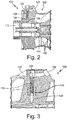
- FIG. 2 is a regional sectional view from attritable engine 100 in FIG. 1 .
- FIG. 2 shows attritable engine 100 including compressor section 102, rotor 110, bearings 112 and 114, compressor blades 116, lubrication system 120, fluid manifold 122, fluid filtering inlet 124, fluid filtering outlet 126, lattice 128 and metering port 134.
- FIG. 3 is another cross-sectional view of the attritable engine including a metering device integrated into the fuel path.
- FIG. 3 shows attritable engine 100 including lubrication system 120, fluid manifold 122, fluid filtering inlet 124, fluid filtering outlet 126, lattice 128, metering port 134, and fluid distribution rail 130.
- Lubrication system 120 provides fluid to bearings 112 and 114 from a fluid source such as, for example, a fuel tank or an oil tank. Fluid can be any fluid that provides cooling to bearings 112 and 114 such as, for example, fuel and oil. Fluid enters lubrication system 120 from a fluid source at fluid manifold 122, which distributes fluid to fluid filtering inlet 124. Fluid manifold 122 can distribute fluid to more than one fluid filtering inlet 124 through fluid distribution rail 130, shown in FIG. 3 . Fluid distribution rail 130 circumferentially travels around the engine casing. Fluid distribution rail 130 may travel all the way around the engine casing or only partially around the engine casing and distribute fluid to multiple fluid filtering inlets 124.
- Lattice 128 is located between fluid filtering inlet 124 and fluid filtering outlet 126.
- Lattice 128 is formed of a repeating pattern of spars that filters the fluid.
- Metering port 134 meters the fluid flow rate through fluid distribution system 120 and is located downstream of lattice 128 and upstream of fluid filtering outlet 126.
- Fluid distribution system 120 can be formed of stainless steel. In other embodiments, fluid distribution system 120 can be formed of aluminum, titanium, copper, cobalt, iron, nickel, and alloys thereof.
- FIG. 4A is a regional sectional view from the attritable engine in FIG. 3 .
- FIG. 4A shows lattice 128 of attritable engine 100 including spars 132, and metering port 134.
- Lattice 128 is formed of multiple spars 132, which are arranged to filter a fluid passing through lattice 128. In other words, particulates present in the fluid which are larger than the passages formed by the arrangement of spars 132 are selectively filtered out of the fluid.
- Spars can be sized and oriented based on various factors such as filtering out particulates of a certain size present in the fluid and manufacturing considerations (some spars 132 sizes and orientations may be easier to manufacture than others).
- Metering port 134 is adjacent to and downstream of spars 132.
- Metering port 134 can be sized to meter the flow rate of the fluid within a target range through fluid distribution system 120.
- FIG. 4B is a regional sectional view from the lattice in FIG. 4A.
- FIG. 4B shows lattice 128 of attritable engine 100 including spars 132A, 132B, 132E, and 132F.
- Spars 132C and 132D is obscured by the other spars in FIG. 4B and, as such, not shown in FIG. 4B .
- FIG. 5 is a perspective view of another embodiment of the repeating lattice structure.
- FIG. 5 shows spar assembly 138 including spars 132A, 132B, 132C, 132D, 132E, and 132F, and center point 136.
- Adjacent spars 132 for example spars 132A and 132B, lie at substantially 90° angles to one another.
- the ends of any three adjacent spars 132, for example spars 132A, 132B, and 132E, which are at an opposing end to center point 136, can form an abstract triangle. Taking all eight sets of three adjacent spars 132 and the resulting abstract triangle from each set of three adjacent spars 132 forms an abstract 3-dimensional shape, which can referred to as a square bipyramid.
- Each spar 132 can have, for example, a diameter of 0.01 inches (0.25 mm). In other embodiments, each spar 132 can have a diameter from 0.005 inches (0.13 mm) to 0.02 inches (0.51 mm), inclusive. In other embodiments, each spar 132 can have a diameter smaller than 0.005 inches (0.13 mm). In other embodiments, each spar 132 can have a diameter larger than 0.02 inches (0.51 mm). Each spar 132 can have a length of 0.05 inches (1.3 mm). In other embodiments, each spar 132 can have a length from 0.03 inches (0.76 mm) to 0.1 inches (2.5 mm), inclusive. In other embodiments, each spar 132 can have a length smaller than 0.03 inches (0.76 mm). In other embodiments, each spar 132 can have a length larger than 0.1 inches (2.5 mm).
- spar assembly 138 includes more than six spars 132. In other embodiments, spar assembly 138 includes fewer than six spars 132. In other embodiments, two adjacent spars 132 can lie at an angle more than 90° from one another. In other embodiments, two adjacent spars 132 can lie at an angle from 45° to 90° from one another.
- Lattice 128 is integral and conformal with attritable engine 100 and can be manufactured using additive manufacturing techniques such as laser powder bed fusion, electron beam melting, and glue binder jetting.
- a fluid dispensing system having an integrated lattice network of spars placed in a lubrication flow pathway unitizes and, simultaneously permits integration of many complex performance-enhancing features.
- the lattice can filter a fluid used to cool the bearings in a gas turbine engine while a metering port can control the flow rate of the fluid through the fluid dispensing system.
- a lubrication system for an attritable engine includes a bearing chamber, a fluid filtering inlet configured to receive a fluid, and a fluid filtering outlet located downstream of the fluid filtering inlet and configured to deliver the fluid to the bearing chamber.
- the lubrication system also includes a lattice, integral and conformal with the attritable engine, configured to filter the fluid, and located between the fluid filtering inlet and the fluid filtering outlet.
- the lubrication system also includes a metering port, configured to meter the fluid and located downstream of the lattice and upstream of the fluid filtering outlet.
- the system of the preceding paragraph can optionally include, additionally and/or alternatively any one or more of the following features, configurations or additional components:
- the lattice is formed of a repeated pattern of spar assemblies.
- Each spar assembly includes six spars.
- the spar assembly has a square bipyramid shape.
- the spars have a diameter from 0.005 inches (0.13 mm) to 0.02 inches (0.51 mm), inclusive.
- the spars have a length from 0.03 inches (0.76 mm) to 0.1 inches (2.5 mm), inclusive.
- the fluid filtering inlet, the fluid filtering outlet, the metering port, and the lattice are formed from a member of the group selected from aluminum, titanium, copper, cobalt, iron, nickel, nickel alloys, stainless steel, and combinations thereof.
- the fluid is fuel for a gas turbine engine.
- the lattice is built in a layer by layer process using additive manufacturing techniques.
- a method of manufacturing an attritable engine lubrication system includes manufacturing a bearing chamber, a fluid filtering inlet configured to receive a fluid, and a fluid filtering outlet located downstream of the fluid filtering inlet and configured to deliver the fluid to the bearing chamber.
- the method also includes manufacturing a lattice, integral and conformal with the attritable engine, configured to filter the fluid, and located between the fluid filtering inlet and the fluid filtering outlet.
- the method also includes manufacturing a metering port, configured to meter the fluid, and located downstream of the lattice and upstream of the fluid filtering outlet.
- the method of the preceding paragraph can optionally include, additionally and/or alternatively any, one or more of the following features, configurations and/or additional components:
- the lattice is formed of a repeated pattern of spar assemblies.
- Each spar assembly includes six spars.
- the spar assembly has a square bipyramid shape.
- the spars have a diameter from 0.005 inches (0.13 mm) to 0.02 inches (0.51 mm), inclusive.
- the spars have a length from 0.03 inches (0.76 mm) to 0.1 inches (2.5 mm), inclusive.
- the fluid filtering inlet, the fluid filtering outlet, the metering port, and the lattice are formed from a member of the group selected from aluminum, titanium, copper, cobalt, iron, nickel, nickel alloys, stainless steel, and combinations thereof.
- the fluid is fuel for a gas turbine engine.
- the lattice is built in a layer by layer process using additive manufacturing techniques.
Landscapes
- Engineering & Computer Science (AREA)
- Mechanical Engineering (AREA)
- General Engineering & Computer Science (AREA)
- Chemical & Material Sciences (AREA)
- Manufacturing & Machinery (AREA)
- Materials Engineering (AREA)
- Combustion & Propulsion (AREA)
- Lubrication Details And Ventilation Of Internal Combustion Engines (AREA)
- Sliding-Contact Bearings (AREA)
- Powder Metallurgy (AREA)
Abstract
Description
- The present disclosure relates generally to attritable aircraft engines. More specifically, this disclosure relates to a fluid dispensing system within an attritable aircraft engine.
- Attritable aircraft can include, for example, Unpiloted (or Unmanned) Aerial Vehicles (UAVs) and expendable turbojet systems for guided munitions, missiles, and decoys. Attritable aircraft are generally designed as a limited lifetime vehicle, which can be as short as a single use or single mission vehicle. As such, many components and features common in traditional piloted aircraft are unnecessary, such as, a fluid dispensing system within a traditional aircraft engine. The fluid dispensing system can have five or more individual parts, each requiring assembly, which can be expensive and time consuming.
- Filters are an important part of the lubrication system because they remove foreign particles that may be in the lubricating fluid. This is particularly important in gas turbines as very high engine speeds are attained; the antifriction types of ball and roller bearings would become damaged quite rapidly if lubricated with contaminated fluids. Also, there are usually numerous drilled or core passages leading to various points of lubrication. Since these passages are usually rather small, they are easily clogged.
- Additionally, metering the lubrication fluid is important. On the one hand, enough lubrication fluid needs to be provided such that sufficient cooling of the bearings are achieved under all working conditions of the gas turbine engine. On the other hand, too much lubrication fluid may require larger fluid pumps and piping system than necessary, increasing the footprint of the lubrication system. Also, pumping unnecessary lubrication fluid through the system uses energy that could be used elsewhere in the gas turbine engine. As such, providing too much lubrication fluid results in a less efficient gas turbine engine compared to a gas turbine engine provided with a proper amount of lubrication fluid.
- In accordance with a first aspect of the disclosure, a lubrication system for an attritable engine includes a bearing chamber, a fluid filtering inlet configured to receive a fluid, and a fluid filtering outlet located downstream of the fluid filtering inlet and configured to deliver the fluid to the bearing chamber. The lubrication system also includes a lattice, integral and conformal with the attritable engine, configured to filter the fluid, and located between the fluid filtering inlet and the fluid filtering outlet. The lubrication system also includes a metering port, configured to meter the fluid and located downstream of the lattice and upstream of the fluid filtering outlet.
- In accordance with a second aspect of the disclosure, a method of manufacturing an attritable engine lubrication system includes manufacturing a bearing chamber, a fluid filtering inlet configured to receive a fluid, and a fluid filtering outlet located downstream of the fluid filtering inlet and configured to deliver the fluid to the bearing chamber. The method also includes manufacturing a lattice, integral and conformal with the attritable engine, configured to filter the fluid, and located between the fluid filtering inlet and the fluid filtering outlet. The method also includes manufacturing a metering port, configured to meter the fluid, and located downstream of the lattice and upstream of the fluid filtering outlet.
-
-
FIG. 1 is a cross-sectional view of an attritable engine. -
FIG. 2 is a regional sectional view from the attritable engine inFIG. 1 . -
FIG. 3 is another cross-sectional view of the attritable engine including a metering device integrated into the fuel path. -
FIG. 4A is a regional sectional view from the attritable engine inFIG. 3 . -
FIG. 4B is a regional sectional view from the lattice inFIG. 4A . -
FIG. 5 is a perspective view of another embodiment of a repeating lattice structure. - An attritable engine with an integrally built fluid dispensing system simplifies manufacturing. Even so, an attritable engine can leverage additive manufacturing techniques to improve various aspects of the limited-life engine. For example, additive manufacturing allows the assembly details to be unitized and, simultaneously permits integration of many complex performance-enhancing features. The additively manufactured engine reduces the time to delivery to the customer and lowers the overall production costs of the unit.
- Disclosed herein is a lubrication system having an integrated lattice network of spars placed in a lubrication flow pathway. The lattice filters a fluid in a gas turbine engine and the fluid is metered by a metering port located downstream of the lattice. The lattice can be built using additive manufacturing techniques such as, for example, laser powder bed fusion, electron beam melting, and glue binder jetting.
-
FIG. 1 is a cross-sectional view of an attritable engine.FIG. 1 showsattritable engine 100 includingcompressor section 102,turbine section 104,exhaust section 106,combustor 108,rotor 110,bearings compressor blades 116,turbine blades 118, and axis of rotation X. In the illustrated embodiment,attritable engine 100 showscompressor section 102 lying forward and adjacent toturbine section 104, which is positioned forward ofexhaust section 106. Althoughcombustor 108 lies physically aft ofturbine section 104,combustor 108 fluidically sits betweencompressor section 102 andturbine section 104. This arrangement may be referred to as a reverse flow combustor.Rotor 110 extends along the axis of rotation X into bothcompressor section 102 andturbine section 104.Rotor 110 is received inbearings rotor 110 arecompressor blades 116 andturbine blades 118. - Operationally, air enters the forward end of
compressor section 102 and is compressed bycompressor blades 116. Compressed air along with fuel enterscombustor 108 where the compressed air and fuel are combusted. The combusted fuel and compressed air fromcombustor 108 entersturbine section 104 and turnsturbine blades 118 circumferentially around rotational axis X, which generates power by also turningrotor 110. The air exits out of the aft end ofexhaust section 106. -
FIGS. 2 and 3 will be discussed together.FIG. 2 is a regional sectional view fromattritable engine 100 inFIG. 1 .FIG. 2 showsattritable engine 100 includingcompressor section 102,rotor 110,bearings compressor blades 116,lubrication system 120,fluid manifold 122,fluid filtering inlet 124,fluid filtering outlet 126,lattice 128 andmetering port 134.FIG. 3 is another cross-sectional view of the attritable engine including a metering device integrated into the fuel path.FIG. 3 showsattritable engine 100 includinglubrication system 120,fluid manifold 122,fluid filtering inlet 124,fluid filtering outlet 126,lattice 128,metering port 134, andfluid distribution rail 130. -
Lubrication system 120 provides fluid tobearings bearings lubrication system 120 from a fluid source atfluid manifold 122, which distributes fluid tofluid filtering inlet 124.Fluid manifold 122 can distribute fluid to more than onefluid filtering inlet 124 throughfluid distribution rail 130, shown inFIG. 3 .Fluid distribution rail 130 circumferentially travels around the engine casing.Fluid distribution rail 130 may travel all the way around the engine casing or only partially around the engine casing and distribute fluid to multiplefluid filtering inlets 124. - Fluid
exits lubrication system 120 atfluid filtering outlet 126 and is then distributed to components withinattritable engine 100 in need of lubrication such asbearings Lattice 128 is located betweenfluid filtering inlet 124 andfluid filtering outlet 126.Lattice 128 is formed of a repeating pattern of spars that filters the fluid.Metering port 134 meters the fluid flow rate throughfluid distribution system 120 and is located downstream oflattice 128 and upstream offluid filtering outlet 126.Fluid distribution system 120 can be formed of stainless steel. In other embodiments,fluid distribution system 120 can be formed of aluminum, titanium, copper, cobalt, iron, nickel, and alloys thereof. -
FIG. 4A is a regional sectional view from the attritable engine inFIG. 3 .FIG. 4A showslattice 128 ofattritable engine 100 includingspars 132, andmetering port 134.Lattice 128 is formed ofmultiple spars 132, which are arranged to filter a fluid passing throughlattice 128. In other words, particulates present in the fluid which are larger than the passages formed by the arrangement ofspars 132 are selectively filtered out of the fluid. Spars can be sized and oriented based on various factors such as filtering out particulates of a certain size present in the fluid and manufacturing considerations (somespars 132 sizes and orientations may be easier to manufacture than others).Metering port 134 is adjacent to and downstream ofspars 132.Metering port 134 can be sized to meter the flow rate of the fluid within a target range throughfluid distribution system 120. -
FIG. 4B is a regional sectional view from the lattice inFIG. 4A. FIG. 4B showslattice 128 ofattritable engine 100 includingspars Spars FIG. 4B and, as such, not shown inFIG. 4B . In the illustrated embodiment, there are sixspars 132 radially extending from a center point at substantially 90° angles to one another, forming a spar assembly. Multiple spar assemblies are formed adjacent one another and together formlattice 128. -
FIG. 5 is a perspective view of another embodiment of the repeating lattice structure.FIG. 5 shows spar assembly 138 includingspars center point 136. In the illustrated embodiment, there are sixspars 132 radially extending from acenter point 136.Adjacent spars 132, for example spars 132A and 132B, lie at substantially 90° angles to one another. The ends of any threeadjacent spars 132, for example spars 132A, 132B, and 132E, which are at an opposing end tocenter point 136, can form an abstract triangle. Taking all eight sets of threeadjacent spars 132 and the resulting abstract triangle from each set of threeadjacent spars 132 forms an abstract 3-dimensional shape, which can referred to as a square bipyramid. - Each
spar 132 can have, for example, a diameter of 0.01 inches (0.25 mm). In other embodiments, eachspar 132 can have a diameter from 0.005 inches (0.13 mm) to 0.02 inches (0.51 mm), inclusive. In other embodiments, eachspar 132 can have a diameter smaller than 0.005 inches (0.13 mm). In other embodiments, eachspar 132 can have a diameter larger than 0.02 inches (0.51 mm). Eachspar 132 can have a length of 0.05 inches (1.3 mm). In other embodiments, eachspar 132 can have a length from 0.03 inches (0.76 mm) to 0.1 inches (2.5 mm), inclusive. In other embodiments, eachspar 132 can have a length smaller than 0.03 inches (0.76 mm). In other embodiments, eachspar 132 can have a length larger than 0.1 inches (2.5 mm). - In other embodiments, spar assembly 138 includes more than six spars 132. In other embodiments, spar assembly 138 includes fewer than six spars 132. In other embodiments, two
adjacent spars 132 can lie at an angle more than 90° from one another. In other embodiments, twoadjacent spars 132 can lie at an angle from 45° to 90° from one another. -
Lattice 128 is integral and conformal withattritable engine 100 and can be manufactured using additive manufacturing techniques such as laser powder bed fusion, electron beam melting, and glue binder jetting. - A fluid dispensing system having an integrated lattice network of spars placed in a lubrication flow pathway unitizes and, simultaneously permits integration of many complex performance-enhancing features. Specifically, the lattice can filter a fluid used to cool the bearings in a gas turbine engine while a metering port can control the flow rate of the fluid through the fluid dispensing system.
- The following are non-exclusive descriptions of possible embodiments of the present invention.
- A lubrication system for an attritable engine includes a bearing chamber, a fluid filtering inlet configured to receive a fluid, and a fluid filtering outlet located downstream of the fluid filtering inlet and configured to deliver the fluid to the bearing chamber. The lubrication system also includes a lattice, integral and conformal with the attritable engine, configured to filter the fluid, and located between the fluid filtering inlet and the fluid filtering outlet. The lubrication system also includes a metering port, configured to meter the fluid and located downstream of the lattice and upstream of the fluid filtering outlet.
- The system of the preceding paragraph can optionally include, additionally and/or alternatively any one or more of the following features, configurations or additional components:
The lattice is formed of a repeated pattern of spar assemblies. - Each spar assembly includes six spars.
- The spar assembly has a square bipyramid shape.
- The spars have a diameter from 0.005 inches (0.13 mm) to 0.02 inches (0.51 mm), inclusive.
- The spars have a length from 0.03 inches (0.76 mm) to 0.1 inches (2.5 mm), inclusive.
- The fluid filtering inlet, the fluid filtering outlet, the metering port, and the lattice are formed from a member of the group selected from aluminum, titanium, copper, cobalt, iron, nickel, nickel alloys, stainless steel, and combinations thereof.
- The fluid is fuel for a gas turbine engine.
- The lattice is built in a layer by layer process using additive manufacturing techniques.
- A method of manufacturing an attritable engine lubrication system includes manufacturing a bearing chamber, a fluid filtering inlet configured to receive a fluid, and a fluid filtering outlet located downstream of the fluid filtering inlet and configured to deliver the fluid to the bearing chamber. The method also includes manufacturing a lattice, integral and conformal with the attritable engine, configured to filter the fluid, and located between the fluid filtering inlet and the fluid filtering outlet. The method also includes manufacturing a metering port, configured to meter the fluid, and located downstream of the lattice and upstream of the fluid filtering outlet.
- The method of the preceding paragraph can optionally include, additionally and/or alternatively any, one or more of the following features, configurations and/or additional components:
The lattice is formed of a repeated pattern of spar assemblies. - Each spar assembly includes six spars.
- The spar assembly has a square bipyramid shape.
- The spars have a diameter from 0.005 inches (0.13 mm) to 0.02 inches (0.51 mm), inclusive.
- The spars have a length from 0.03 inches (0.76 mm) to 0.1 inches (2.5 mm), inclusive.
- The fluid filtering inlet, the fluid filtering outlet, the metering port, and the lattice are formed from a member of the group selected from aluminum, titanium, copper, cobalt, iron, nickel, nickel alloys, stainless steel, and combinations thereof.
- The fluid is fuel for a gas turbine engine.
- The lattice is built in a layer by layer process using additive manufacturing techniques.
- While the invention has been described with reference to an exemplary embodiments), it will be understood by those skilled in the art that various changes may be made and equivalents may be substituted for elements thereof without departing from the scope of the invention. In addition, many modifications may be made to adapt a particular situation or material to the teachings of the invention without departing from the essential scope thereof. Therefore, it is intended that the invention not be limited to the particular embodiments) disclosed, but that the invention will include all embodiments falling within the scope of the appended claims.
Claims (11)
- A lubrication system (120) for an attritable engine (100), the lubrication system (120) comprising:a bearing chamber;a fluid filtering inlet (124) configured to receive a fluid;a fluid filtering outlet (126) located downstream of the fluid filtering inlet (124) and configured to deliver the fluid to the bearing chamber;a lattice (128), integral and conformal with the attritable engine (100), configured to filter the fluid, and located between the fluid filtering inlet (124) and the fluid filtering outlet (126); anda metering port (134), configured to meter the fluid and located downstream of the lattice (128) and upstream of the fluid filtering outlet (126).
- The system of claim 1, wherein the lattice (128) is built in a layer by layer process using additive manufacturing techniques.
- A method of manufacturing an attritable engine (100) lubrication system (120), the method comprising:manufacturing a bearing chamber, a fluid filtering inlet (124) configured to receive a fluid, and a fluid filtering outlet (126) located downstream of the fluid filtering inlet (124) and configured to deliver the fluid to the bearing chamber;manufacturing a lattice (128), integral and conformal with the attritable engine (100), configured to filter the fluid, and located between the fluid filtering inlet (124) and the fluid filtering outlet (126); andmanufacturing a metering port (134), configured to meter the fluid, and located downstream of the lattice (128) and upstream of the fluid filtering outlet (126).
- The method of claim 3 wherein manufacturing the lattice (128) is performed using additive manufacturing techniques.
- The system or method of any preceding claim, wherein the lattice (128) is formed of a repeated pattern of spar assemblies (138).
- The system or method of claim 5, wherein the spar assembly (138) has a square bipyramid shape.
- The system or method of claim 5 or 6, wherein each spar assembly (138) includes six spars (132).
- The system or method of claim 7, wherein the spars (132) have a diameter from 0.005 inches (0.13 mm) to 0.02 inches (0.51 mm), inclusive.
- The system or method of claim 7 or 8, wherein the spars (132) have a length from 0.03 inches (0.76 mm) to 0.1 inches (2.5 mm), inclusive.
- The system or method of any preceding claim, wherein the fluid filtering inlet (124), the fluid filtering outlet (126), the metering port (134), and the lattice (128) are formed from a member of the group selected from aluminum, titanium, copper, cobalt, iron, nickel, nickel alloys, stainless steel, and combinations thereof.
- The system or method of any preceding claim, wherein the fluid is fuel for a gas turbine engine.
Applications Claiming Priority (1)
| Application Number | Priority Date | Filing Date | Title |
|---|---|---|---|
| US16/577,526 US11542844B2 (en) | 2019-09-20 | 2019-09-20 | Integrated lubricating fluid filtering and metering device |
Publications (2)
| Publication Number | Publication Date |
|---|---|
| EP3795806A1 true EP3795806A1 (en) | 2021-03-24 |
| EP3795806B1 EP3795806B1 (en) | 2024-10-30 |
Family
ID=72561686
Family Applications (1)
| Application Number | Title | Priority Date | Filing Date |
|---|---|---|---|
| EP20196960.7A Active EP3795806B1 (en) | 2019-09-20 | 2020-09-18 | Lubrication system with integrated lubricating fluid filtering and metering device |
Country Status (2)
| Country | Link |
|---|---|
| US (1) | US11542844B2 (en) |
| EP (1) | EP3795806B1 (en) |
Families Citing this family (3)
| Publication number | Priority date | Publication date | Assignee | Title |
|---|---|---|---|---|
| US12055062B2 (en) * | 2022-10-28 | 2024-08-06 | Rtx Corporation | Gas turbine engine support structure with internal lattice |
| US12523156B2 (en) * | 2023-05-23 | 2026-01-13 | Rtx Corporation | Turbine engine structure with an integral fluid reservoir |
| US12529337B1 (en) | 2024-11-18 | 2026-01-20 | Rtx Corporation | Additively manufactured turbine engine case with fuel manifold |
Citations (4)
| Publication number | Priority date | Publication date | Assignee | Title |
|---|---|---|---|---|
| EP1803897A2 (en) * | 2005-10-26 | 2007-07-04 | Rolls-Royce plc | Gas turbine blade wall cooling arrangement |
| KR20110091387A (en) * | 2010-02-05 | 2011-08-11 | 국방과학연구소 | Turbojet engine |
| WO2014133836A1 (en) * | 2013-02-28 | 2014-09-04 | United Technologies Corporation | Self cleaning debris filter for fan drive gear system |
| US20190249558A1 (en) * | 2018-02-13 | 2019-08-15 | Safran Aircraft Engines | Outlet guide vane for turbomachine, made from several parts assembled together by attachment means outside the flow stream |
Family Cites Families (13)
| Publication number | Priority date | Publication date | Assignee | Title |
|---|---|---|---|---|
| US3692041A (en) | 1971-01-04 | 1972-09-19 | Gen Electric | Variable flow distributor |
| US7172694B2 (en) | 2003-01-24 | 2007-02-06 | Schroeder Industries, Llc | Filter assembly |
| US7748208B2 (en) * | 2006-12-04 | 2010-07-06 | Hamilton Sundstrand Corporation | Compact recirculating lubrication system for a miniature gas turbine engine |
| US20110137333A1 (en) * | 2009-12-04 | 2011-06-09 | Boston Scientific Scimed, Inc. | Embolic protection device |
| DE102012210834A1 (en) * | 2012-06-26 | 2014-01-02 | Hengst Gmbh & Co. Kg | Liquid filter with a filter bypass valve and a central discharge channel and filter insert for a liquid filter |
| WO2015042089A1 (en) | 2013-09-23 | 2015-03-26 | United Technologies Corporation | Method of generating support structure of tube components to become functional features |
| EP3055605A4 (en) | 2013-10-07 | 2017-06-28 | United Technologies Corporation | Article with internal structure |
| GB201507130D0 (en) * | 2015-04-27 | 2015-06-10 | Alcon Components Ltd | Brake caliper body and method of manufacture of a brake caliper body |
| CN105033188A (en) * | 2015-05-22 | 2015-11-11 | 中国科学院固体物理研究所 | Aluminum-based dot matrix material based on 3D printing technology and preparation method thereof |
| US10072632B2 (en) * | 2015-06-30 | 2018-09-11 | General Electric Company | Spar cap for a wind turbine rotor blade formed from pre-cured laminate plates of varying thicknesses |
| US10221694B2 (en) | 2016-02-17 | 2019-03-05 | United Technologies Corporation | Gas turbine engine component having vascular engineered lattice structure |
| US20180347442A1 (en) | 2017-05-31 | 2018-12-06 | General Electric Company | Lattice structure in cooling pathway by additive manufacture |
| JP2020157236A (en) * | 2019-03-27 | 2020-10-01 | 三菱日立パワーシステムズ株式会社 | Metal filter and method for producing the same |
-
2019
- 2019-09-20 US US16/577,526 patent/US11542844B2/en active Active
-
2020
- 2020-09-18 EP EP20196960.7A patent/EP3795806B1/en active Active
Patent Citations (4)
| Publication number | Priority date | Publication date | Assignee | Title |
|---|---|---|---|---|
| EP1803897A2 (en) * | 2005-10-26 | 2007-07-04 | Rolls-Royce plc | Gas turbine blade wall cooling arrangement |
| KR20110091387A (en) * | 2010-02-05 | 2011-08-11 | 국방과학연구소 | Turbojet engine |
| WO2014133836A1 (en) * | 2013-02-28 | 2014-09-04 | United Technologies Corporation | Self cleaning debris filter for fan drive gear system |
| US20190249558A1 (en) * | 2018-02-13 | 2019-08-15 | Safran Aircraft Engines | Outlet guide vane for turbomachine, made from several parts assembled together by attachment means outside the flow stream |
Also Published As
| Publication number | Publication date |
|---|---|
| EP3795806B1 (en) | 2024-10-30 |
| US20210087955A1 (en) | 2021-03-25 |
| US11542844B2 (en) | 2023-01-03 |
Similar Documents
| Publication | Publication Date | Title |
|---|---|---|
| EP3795806B1 (en) | Lubrication system with integrated lubricating fluid filtering and metering device | |
| EP3486595B1 (en) | Contoured wall heat exchanger | |
| US20200300389A1 (en) | Fluid couplings and methods for additive manufacturing thereof | |
| US11021963B2 (en) | Monolithic body including an internal passage with a generally teardrop shaped cross-sectional geometry | |
| US10934890B2 (en) | Shrouded conduit for arranging a fluid flowpath | |
| EP3486429B1 (en) | Ogv electroformed heat exchangers | |
| US12312970B2 (en) | Lubrication network for an attritable engine | |
| US20180038654A1 (en) | System for fault tolerant passage arrangements for heat exchanger applications | |
| EP3748148B1 (en) | Attritable engine additively manufactured inlet cap | |
| GB2601700A (en) | Casing integrated fluid distribution system | |
| EP4481314A1 (en) | Composite heat exchange apparatus for a turbine engine | |
| US10731472B2 (en) | Airfoil with cooling circuit | |
| US11994071B2 (en) | Fuel system having a coke filtration system | |
| US20180094543A1 (en) | Insert apparatus and system for oil nozzle boundary layer injection | |
| US20170328213A1 (en) | Engine component wall with a cooling circuit |
Legal Events
| Date | Code | Title | Description |
|---|---|---|---|
| PUAI | Public reference made under article 153(3) epc to a published international application that has entered the european phase |
Free format text: ORIGINAL CODE: 0009012 |
|
| STAA | Information on the status of an ep patent application or granted ep patent |
Free format text: STATUS: THE APPLICATION HAS BEEN PUBLISHED |
|
| AK | Designated contracting states |
Kind code of ref document: A1 Designated state(s): AL AT BE BG CH CY CZ DE DK EE ES FI FR GB GR HR HU IE IS IT LI LT LU LV MC MK MT NL NO PL PT RO RS SE SI SK SM TR |
|
| AX | Request for extension of the european patent |
Extension state: BA ME |
|
| STAA | Information on the status of an ep patent application or granted ep patent |
Free format text: STATUS: REQUEST FOR EXAMINATION WAS MADE |
|
| 17P | Request for examination filed |
Effective date: 20210913 |
|
| RBV | Designated contracting states (corrected) |
Designated state(s): AL AT BE BG CH CY CZ DE DK EE ES FI FR GB GR HR HU IE IS IT LI LT LU LV MC MK MT NL NO PL PT RO RS SE SI SK SM TR |
|
| STAA | Information on the status of an ep patent application or granted ep patent |
Free format text: STATUS: EXAMINATION IS IN PROGRESS |
|
| 17Q | First examination report despatched |
Effective date: 20220915 |
|
| RAP3 | Party data changed (applicant data changed or rights of an application transferred) |
Owner name: RTX CORPORATION |
|
| REG | Reference to a national code |
Ref country code: DE Ref legal event code: R079 Free format text: PREVIOUS MAIN CLASS: F01D0025180000 Ipc: B22F0003110000 Ref country code: DE Ref legal event code: R079 Ref document number: 602020040198 Country of ref document: DE Free format text: PREVIOUS MAIN CLASS: F01D0025180000 Ipc: B22F0003110000 |
|
| GRAP | Despatch of communication of intention to grant a patent |
Free format text: ORIGINAL CODE: EPIDOSNIGR1 |
|
| STAA | Information on the status of an ep patent application or granted ep patent |
Free format text: STATUS: GRANT OF PATENT IS INTENDED |
|
| RIC1 | Information provided on ipc code assigned before grant |
Ipc: F02C 7/06 20060101ALI20240502BHEP Ipc: F01D 25/12 20060101ALI20240502BHEP Ipc: F01D 25/16 20060101ALI20240502BHEP Ipc: F01D 25/22 20060101ALI20240502BHEP Ipc: F01D 25/18 20060101ALI20240502BHEP Ipc: B33Y 80/00 20150101ALI20240502BHEP Ipc: B33Y 10/00 20150101ALI20240502BHEP Ipc: B22F 5/00 20060101ALI20240502BHEP Ipc: B22F 3/11 20060101AFI20240502BHEP |
|
| INTG | Intention to grant announced |
Effective date: 20240522 |
|
| GRAS | Grant fee paid |
Free format text: ORIGINAL CODE: EPIDOSNIGR3 |
|
| GRAA | (expected) grant |
Free format text: ORIGINAL CODE: 0009210 |
|
| STAA | Information on the status of an ep patent application or granted ep patent |
Free format text: STATUS: THE PATENT HAS BEEN GRANTED |
|
| AK | Designated contracting states |
Kind code of ref document: B1 Designated state(s): AL AT BE BG CH CY CZ DE DK EE ES FI FR GB GR HR HU IE IS IT LI LT LU LV MC MK MT NL NO PL PT RO RS SE SI SK SM TR |
|
| REG | Reference to a national code |
Ref country code: GB Ref legal event code: FG4D |
|
| REG | Reference to a national code |
Ref country code: CH Ref legal event code: EP |
|
| REG | Reference to a national code |
Ref country code: IE Ref legal event code: FG4D |
|
| REG | Reference to a national code |
Ref country code: DE Ref legal event code: R096 Ref document number: 602020040198 Country of ref document: DE |
|
| REG | Reference to a national code |
Ref country code: LT Ref legal event code: MG9D |
|
| REG | Reference to a national code |
Ref country code: NL Ref legal event code: MP Effective date: 20241030 |
|
| PG25 | Lapsed in a contracting state [announced via postgrant information from national office to epo] |
Ref country code: IS Free format text: LAPSE BECAUSE OF FAILURE TO SUBMIT A TRANSLATION OF THE DESCRIPTION OR TO PAY THE FEE WITHIN THE PRESCRIBED TIME-LIMIT Effective date: 20250228 Ref country code: PT Free format text: LAPSE BECAUSE OF FAILURE TO SUBMIT A TRANSLATION OF THE DESCRIPTION OR TO PAY THE FEE WITHIN THE PRESCRIBED TIME-LIMIT Effective date: 20250228 Ref country code: HR Free format text: LAPSE BECAUSE OF FAILURE TO SUBMIT A TRANSLATION OF THE DESCRIPTION OR TO PAY THE FEE WITHIN THE PRESCRIBED TIME-LIMIT Effective date: 20241030 |
|
| PG25 | Lapsed in a contracting state [announced via postgrant information from national office to epo] |
Ref country code: FI Free format text: LAPSE BECAUSE OF FAILURE TO SUBMIT A TRANSLATION OF THE DESCRIPTION OR TO PAY THE FEE WITHIN THE PRESCRIBED TIME-LIMIT Effective date: 20241030 Ref country code: NL Free format text: LAPSE BECAUSE OF FAILURE TO SUBMIT A TRANSLATION OF THE DESCRIPTION OR TO PAY THE FEE WITHIN THE PRESCRIBED TIME-LIMIT Effective date: 20241030 |
|
| REG | Reference to a national code |
Ref country code: AT Ref legal event code: MK05 Ref document number: 1736427 Country of ref document: AT Kind code of ref document: T Effective date: 20241030 |
|
| PG25 | Lapsed in a contracting state [announced via postgrant information from national office to epo] |
Ref country code: BG Free format text: LAPSE BECAUSE OF FAILURE TO SUBMIT A TRANSLATION OF THE DESCRIPTION OR TO PAY THE FEE WITHIN THE PRESCRIBED TIME-LIMIT Effective date: 20241030 |
|
| PG25 | Lapsed in a contracting state [announced via postgrant information from national office to epo] |
Ref country code: ES Free format text: LAPSE BECAUSE OF FAILURE TO SUBMIT A TRANSLATION OF THE DESCRIPTION OR TO PAY THE FEE WITHIN THE PRESCRIBED TIME-LIMIT Effective date: 20241030 |
|
| PG25 | Lapsed in a contracting state [announced via postgrant information from national office to epo] |
Ref country code: NO Free format text: LAPSE BECAUSE OF FAILURE TO SUBMIT A TRANSLATION OF THE DESCRIPTION OR TO PAY THE FEE WITHIN THE PRESCRIBED TIME-LIMIT Effective date: 20250130 |
|
| PG25 | Lapsed in a contracting state [announced via postgrant information from national office to epo] |
Ref country code: AT Free format text: LAPSE BECAUSE OF FAILURE TO SUBMIT A TRANSLATION OF THE DESCRIPTION OR TO PAY THE FEE WITHIN THE PRESCRIBED TIME-LIMIT Effective date: 20241030 Ref country code: LV Free format text: LAPSE BECAUSE OF FAILURE TO SUBMIT A TRANSLATION OF THE DESCRIPTION OR TO PAY THE FEE WITHIN THE PRESCRIBED TIME-LIMIT Effective date: 20241030 Ref country code: GR Free format text: LAPSE BECAUSE OF FAILURE TO SUBMIT A TRANSLATION OF THE DESCRIPTION OR TO PAY THE FEE WITHIN THE PRESCRIBED TIME-LIMIT Effective date: 20250131 |
|
| PG25 | Lapsed in a contracting state [announced via postgrant information from national office to epo] |
Ref country code: PL Free format text: LAPSE BECAUSE OF FAILURE TO SUBMIT A TRANSLATION OF THE DESCRIPTION OR TO PAY THE FEE WITHIN THE PRESCRIBED TIME-LIMIT Effective date: 20241030 |
|
| PG25 | Lapsed in a contracting state [announced via postgrant information from national office to epo] |
Ref country code: RS Free format text: LAPSE BECAUSE OF FAILURE TO SUBMIT A TRANSLATION OF THE DESCRIPTION OR TO PAY THE FEE WITHIN THE PRESCRIBED TIME-LIMIT Effective date: 20250130 |
|
| PG25 | Lapsed in a contracting state [announced via postgrant information from national office to epo] |
Ref country code: SM Free format text: LAPSE BECAUSE OF FAILURE TO SUBMIT A TRANSLATION OF THE DESCRIPTION OR TO PAY THE FEE WITHIN THE PRESCRIBED TIME-LIMIT Effective date: 20241030 |
|
| PG25 | Lapsed in a contracting state [announced via postgrant information from national office to epo] |
Ref country code: DK Free format text: LAPSE BECAUSE OF FAILURE TO SUBMIT A TRANSLATION OF THE DESCRIPTION OR TO PAY THE FEE WITHIN THE PRESCRIBED TIME-LIMIT Effective date: 20241030 |
|
| PG25 | Lapsed in a contracting state [announced via postgrant information from national office to epo] |
Ref country code: EE Free format text: LAPSE BECAUSE OF FAILURE TO SUBMIT A TRANSLATION OF THE DESCRIPTION OR TO PAY THE FEE WITHIN THE PRESCRIBED TIME-LIMIT Effective date: 20241030 |
|
| PG25 | Lapsed in a contracting state [announced via postgrant information from national office to epo] |
Ref country code: RO Free format text: LAPSE BECAUSE OF FAILURE TO SUBMIT A TRANSLATION OF THE DESCRIPTION OR TO PAY THE FEE WITHIN THE PRESCRIBED TIME-LIMIT Effective date: 20241030 |
|
| PG25 | Lapsed in a contracting state [announced via postgrant information from national office to epo] |
Ref country code: SK Free format text: LAPSE BECAUSE OF FAILURE TO SUBMIT A TRANSLATION OF THE DESCRIPTION OR TO PAY THE FEE WITHIN THE PRESCRIBED TIME-LIMIT Effective date: 20241030 |
|
| PG25 | Lapsed in a contracting state [announced via postgrant information from national office to epo] |
Ref country code: CZ Free format text: LAPSE BECAUSE OF FAILURE TO SUBMIT A TRANSLATION OF THE DESCRIPTION OR TO PAY THE FEE WITHIN THE PRESCRIBED TIME-LIMIT Effective date: 20241030 |
|
| PG25 | Lapsed in a contracting state [announced via postgrant information from national office to epo] |
Ref country code: IT Free format text: LAPSE BECAUSE OF FAILURE TO SUBMIT A TRANSLATION OF THE DESCRIPTION OR TO PAY THE FEE WITHIN THE PRESCRIBED TIME-LIMIT Effective date: 20241030 |
|
| REG | Reference to a national code |
Ref country code: DE Ref legal event code: R097 Ref document number: 602020040198 Country of ref document: DE |
|
| PLBE | No opposition filed within time limit |
Free format text: ORIGINAL CODE: 0009261 |
|
| STAA | Information on the status of an ep patent application or granted ep patent |
Free format text: STATUS: NO OPPOSITION FILED WITHIN TIME LIMIT |
|
| PG25 | Lapsed in a contracting state [announced via postgrant information from national office to epo] |
Ref country code: SE Free format text: LAPSE BECAUSE OF FAILURE TO SUBMIT A TRANSLATION OF THE DESCRIPTION OR TO PAY THE FEE WITHIN THE PRESCRIBED TIME-LIMIT Effective date: 20241030 |
|
| 26N | No opposition filed |
Effective date: 20250731 |
|
| PGFP | Annual fee paid to national office [announced via postgrant information from national office to epo] |
Ref country code: DE Payment date: 20250820 Year of fee payment: 6 |
|
| PGFP | Annual fee paid to national office [announced via postgrant information from national office to epo] |
Ref country code: GB Payment date: 20250820 Year of fee payment: 6 |
|
| PGFP | Annual fee paid to national office [announced via postgrant information from national office to epo] |
Ref country code: FR Payment date: 20250820 Year of fee payment: 6 |