EP3795802A1 - A gas turbine engine - Google Patents
A gas turbine engine Download PDFInfo
- Publication number
- EP3795802A1 EP3795802A1 EP20192299.4A EP20192299A EP3795802A1 EP 3795802 A1 EP3795802 A1 EP 3795802A1 EP 20192299 A EP20192299 A EP 20192299A EP 3795802 A1 EP3795802 A1 EP 3795802A1
- Authority
- EP
- European Patent Office
- Prior art keywords
- restrictor
- turbine engine
- gas turbine
- operational
- gas
- Prior art date
- Legal status (The legal status is an assumption and is not a legal conclusion. Google has not performed a legal analysis and makes no representation as to the accuracy of the status listed.)
- Granted
Links
Images




Classifications
-
- F—MECHANICAL ENGINEERING; LIGHTING; HEATING; WEAPONS; BLASTING
- F01—MACHINES OR ENGINES IN GENERAL; ENGINE PLANTS IN GENERAL; STEAM ENGINES
- F01D—NON-POSITIVE DISPLACEMENT MACHINES OR ENGINES, e.g. STEAM TURBINES
- F01D19/00—Starting of machines or engines; Regulating, controlling, or safety means in connection therewith
-
- F—MECHANICAL ENGINEERING; LIGHTING; HEATING; WEAPONS; BLASTING
- F01—MACHINES OR ENGINES IN GENERAL; ENGINE PLANTS IN GENERAL; STEAM ENGINES
- F01D—NON-POSITIVE DISPLACEMENT MACHINES OR ENGINES, e.g. STEAM TURBINES
- F01D17/00—Regulating or controlling by varying flow
-
- F—MECHANICAL ENGINEERING; LIGHTING; HEATING; WEAPONS; BLASTING
- F01—MACHINES OR ENGINES IN GENERAL; ENGINE PLANTS IN GENERAL; STEAM ENGINES
- F01D—NON-POSITIVE DISPLACEMENT MACHINES OR ENGINES, e.g. STEAM TURBINES
- F01D17/00—Regulating or controlling by varying flow
- F01D17/10—Final actuators
- F01D17/12—Final actuators arranged in stator parts
- F01D17/14—Final actuators arranged in stator parts varying effective cross-sectional area of nozzles or guide conduits
-
- F—MECHANICAL ENGINEERING; LIGHTING; HEATING; WEAPONS; BLASTING
- F01—MACHINES OR ENGINES IN GENERAL; ENGINE PLANTS IN GENERAL; STEAM ENGINES
- F01D—NON-POSITIVE DISPLACEMENT MACHINES OR ENGINES, e.g. STEAM TURBINES
- F01D5/00—Blades; Blade-carrying members; Heating, heat-insulating, cooling or antivibration means on the blades or the members
- F01D5/12—Blades
- F01D5/14—Form or construction
- F01D5/141—Shape, i.e. outer, aerodynamic form
- F01D5/142—Shape, i.e. outer, aerodynamic form of the blades of successive rotor or stator blade-rows
-
- F—MECHANICAL ENGINEERING; LIGHTING; HEATING; WEAPONS; BLASTING
- F01—MACHINES OR ENGINES IN GENERAL; ENGINE PLANTS IN GENERAL; STEAM ENGINES
- F01D—NON-POSITIVE DISPLACEMENT MACHINES OR ENGINES, e.g. STEAM TURBINES
- F01D5/00—Blades; Blade-carrying members; Heating, heat-insulating, cooling or antivibration means on the blades or the members
- F01D5/12—Blades
- F01D5/28—Selecting particular materials; Particular measures relating thereto; Measures against erosion or corrosion
-
- F—MECHANICAL ENGINEERING; LIGHTING; HEATING; WEAPONS; BLASTING
- F01—MACHINES OR ENGINES IN GENERAL; ENGINE PLANTS IN GENERAL; STEAM ENGINES
- F01D—NON-POSITIVE DISPLACEMENT MACHINES OR ENGINES, e.g. STEAM TURBINES
- F01D9/00—Stators
- F01D9/02—Nozzles; Nozzle boxes; Stator blades; Guide conduits, e.g. individual nozzles
- F01D9/04—Nozzles; Nozzle boxes; Stator blades; Guide conduits, e.g. individual nozzles forming ring or sector
- F01D9/041—Nozzles; Nozzle boxes; Stator blades; Guide conduits, e.g. individual nozzles forming ring or sector using blades
-
- F—MECHANICAL ENGINEERING; LIGHTING; HEATING; WEAPONS; BLASTING
- F01—MACHINES OR ENGINES IN GENERAL; ENGINE PLANTS IN GENERAL; STEAM ENGINES
- F01D—NON-POSITIVE DISPLACEMENT MACHINES OR ENGINES, e.g. STEAM TURBINES
- F01D9/00—Stators
- F01D9/02—Nozzles; Nozzle boxes; Stator blades; Guide conduits, e.g. individual nozzles
- F01D9/04—Nozzles; Nozzle boxes; Stator blades; Guide conduits, e.g. individual nozzles forming ring or sector
- F01D9/045—Nozzles; Nozzle boxes; Stator blades; Guide conduits, e.g. individual nozzles forming ring or sector for radial flow machines or engines
-
- F—MECHANICAL ENGINEERING; LIGHTING; HEATING; WEAPONS; BLASTING
- F02—COMBUSTION ENGINES; HOT-GAS OR COMBUSTION-PRODUCT ENGINE PLANTS
- F02C—GAS-TURBINE PLANTS; AIR INTAKES FOR JET-PROPULSION PLANTS; CONTROLLING FUEL SUPPLY IN AIR-BREATHING JET-PROPULSION PLANTS
- F02C9/00—Controlling gas-turbine plants; Controlling fuel supply in air- breathing jet-propulsion plants
- F02C9/26—Control of fuel supply
-
- F—MECHANICAL ENGINEERING; LIGHTING; HEATING; WEAPONS; BLASTING
- F05—INDEXING SCHEMES RELATING TO ENGINES OR PUMPS IN VARIOUS SUBCLASSES OF CLASSES F01-F04
- F05D—INDEXING SCHEME FOR ASPECTS RELATING TO NON-POSITIVE-DISPLACEMENT MACHINES OR ENGINES, GAS-TURBINES OR JET-PROPULSION PLANTS
- F05D2230/00—Manufacture
- F05D2230/90—Coating; Surface treatment
-
- F—MECHANICAL ENGINEERING; LIGHTING; HEATING; WEAPONS; BLASTING
- F05—INDEXING SCHEMES RELATING TO ENGINES OR PUMPS IN VARIOUS SUBCLASSES OF CLASSES F01-F04
- F05D—INDEXING SCHEME FOR ASPECTS RELATING TO NON-POSITIVE-DISPLACEMENT MACHINES OR ENGINES, GAS-TURBINES OR JET-PROPULSION PLANTS
- F05D2240/00—Components
- F05D2240/10—Stators
- F05D2240/12—Fluid guiding means, e.g. vanes
-
- F—MECHANICAL ENGINEERING; LIGHTING; HEATING; WEAPONS; BLASTING
- F05—INDEXING SCHEMES RELATING TO ENGINES OR PUMPS IN VARIOUS SUBCLASSES OF CLASSES F01-F04
- F05D—INDEXING SCHEME FOR ASPECTS RELATING TO NON-POSITIVE-DISPLACEMENT MACHINES OR ENGINES, GAS-TURBINES OR JET-PROPULSION PLANTS
- F05D2240/00—Components
- F05D2240/80—Platforms for stationary or moving blades
-
- F—MECHANICAL ENGINEERING; LIGHTING; HEATING; WEAPONS; BLASTING
- F05—INDEXING SCHEMES RELATING TO ENGINES OR PUMPS IN VARIOUS SUBCLASSES OF CLASSES F01-F04
- F05D—INDEXING SCHEME FOR ASPECTS RELATING TO NON-POSITIVE-DISPLACEMENT MACHINES OR ENGINES, GAS-TURBINES OR JET-PROPULSION PLANTS
- F05D2260/00—Function
- F05D2260/85—Starting
-
- F—MECHANICAL ENGINEERING; LIGHTING; HEATING; WEAPONS; BLASTING
- F05—INDEXING SCHEMES RELATING TO ENGINES OR PUMPS IN VARIOUS SUBCLASSES OF CLASSES F01-F04
- F05D—INDEXING SCHEME FOR ASPECTS RELATING TO NON-POSITIVE-DISPLACEMENT MACHINES OR ENGINES, GAS-TURBINES OR JET-PROPULSION PLANTS
- F05D2300/00—Materials; Properties thereof
- F05D2300/10—Metals, alloys or intermetallic compounds
- F05D2300/16—Other metals not provided for in groups F05D2300/11 - F05D2300/15
- F05D2300/1612—Lead
-
- F—MECHANICAL ENGINEERING; LIGHTING; HEATING; WEAPONS; BLASTING
- F05—INDEXING SCHEMES RELATING TO ENGINES OR PUMPS IN VARIOUS SUBCLASSES OF CLASSES F01-F04
- F05D—INDEXING SCHEME FOR ASPECTS RELATING TO NON-POSITIVE-DISPLACEMENT MACHINES OR ENGINES, GAS-TURBINES OR JET-PROPULSION PLANTS
- F05D2300/00—Materials; Properties thereof
- F05D2300/10—Metals, alloys or intermetallic compounds
- F05D2300/16—Other metals not provided for in groups F05D2300/11 - F05D2300/15
- F05D2300/1614—Tin
-
- F—MECHANICAL ENGINEERING; LIGHTING; HEATING; WEAPONS; BLASTING
- F05—INDEXING SCHEMES RELATING TO ENGINES OR PUMPS IN VARIOUS SUBCLASSES OF CLASSES F01-F04
- F05D—INDEXING SCHEME FOR ASPECTS RELATING TO NON-POSITIVE-DISPLACEMENT MACHINES OR ENGINES, GAS-TURBINES OR JET-PROPULSION PLANTS
- F05D2300/00—Materials; Properties thereof
- F05D2300/10—Metals, alloys or intermetallic compounds
- F05D2300/17—Alloys
Definitions
- the present disclosure relates to a gas turbine engine and a method of starting a gas turbine engine.
- Combustor loading is a parameter used to indicate the stability of combustion based on mass flow rate, pressure and combustor volume. Combustor loading can be reduced by increasing the combustor volume. At altitude, the air pressure is relatively low, therefore the combustor volume needs to be high to achieve a sufficiently low combustor loading to be able to achieve ignition.
- increasing the combustor volume is undesirable as it results in a significant increase in the size and weight of the engine, leading to further fuel and material cost.
- the present disclosure provides a gas turbine engine and a method of starting a gas turbine engine as set out in the appended claims.
- a gas turbine engine comprising: a combustor configured to initiate combustion; and a turbine comprising a stator vane ring defining a plurality of passageways between adjacent vanes; wherein at least one of the passageways is provided with a restrictor which defines a temporary gas washed surface for the stator vane ring and is configured to be ablated upon initiation of combustion to reveal an operational gas washed surface of the stator vane ring.
- Ablation includes, but is not limited to, the following: erosion, vaporisation, chipping, burning, and melting.
- the passageway comprises circumferentially extending endwalls between adjacent vanes.
- the restrictor may be provided on an operational gas washed surface of the endwalls.
- the restrictor may be provided on the operational gas washed surface of a vane delimiting the passageway.
- the restrictor may be a coating provided on the endwalls.
- the coating may at least partially cover an operational gas washed surface of the endwalls.
- the restrictor may be a coating provided on a vane delimiting the passageway.
- the coating may at least partially cover the operational gas washed surface of the respective vane.
- the coating may completely cover the operational gas washed surface of the respective vane.
- the coating may be formed from tin or an alloy of lead and tin.
- the restrictor may be an insert configured to cooperate with the stator vane to prevent downstream ejection prior to ablation. It may be that each passageway narrows from an inlet to an outlet. It may be that the insert is configured to be received in the inlet and that the outlet is configured to prevent ejection of the insert prior to ablation.
- the insert may be formed from a paper-based material or a card-based material.
- the passageway may define an operational flow area.
- the restrictor may be configured to restrict the operational flow area by at least 50% of the operational flow area.
- the restrictor is configured to commence ablation when the combustor exit temperature is from 200 °C to 600 °C.
- a method of starting a gas turbine engine comprising the steps of: providing a gas turbine engine comprising a combustor configured to initiate combustion and a turbine comprising a stator vane ring defining a plurality of passageways between adjacent vanes; providing at least one of the passageways with a restrictor defining a temporary gas washed surface for the stator vane ring; and initiating combustion in the combustor to increase the temperature of flow exiting the combustor and thereby ablating the restrictor to reveal an operational gas washed surface of the stator vane ring.
- the restrictor may be a coating. It may be that providing at least one of the passageways with the restrictor comprises applying the coating to an operational gas washed surface of the stator vane ring.
- the coating may be applied by spraying or painting.
- the restrictor may be an insert. It may be that providing at least one of the passageways with the restrictor comprises installing the insert in the stator vane ring to cover an operational gas washed surface of the stator vane ring.
- the insert may be formed from a paper-based material or a card-based material.
- the restrictor may be provided on an operational gas washed surface of a vane delimiting the passageway.
- the restrictor may be provided on an operational gas washed surface of an endwall, the endwall circumferentially extending between adjacent vanes.
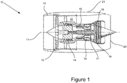
- a gas turbine engine is generally indicated at 10, having a principal and rotational axis 11.
- the engine 10 comprises, in axial flow series, an air intake 12, a propulsive fan 13, an intermediate pressure compressor 14, a high-pressure compressor 15, a combustor 16, a high-pressure turbine 17, an intermediate pressure turbine 18, a low-pressure turbine 19 and an exhaust nozzle 20.
- a nacelle 21 generally surrounds the engine 10 and defines both the intake 12 and the exhaust nozzle 20.
- the gas turbine engine 10 works in the conventional manner so that air entering the intake 12 is accelerated by the fan 13 to produce two air flows: a first air flow into the intermediate pressure compressor 14 and a second air flow which passes through a bypass duct 22 to provide propulsive thrust.
- the intermediate pressure compressor 14 compresses the air flow directed into it before delivering that air to the high pressure compressor 15 where further compression takes place.
- the compressed air exhausted from the high-pressure compressor 15 is directed into the combustor 16 where it is mixed with fuel and the mixture combusted.
- the resultant hot combustion products then expand through, and thereby drive the high, intermediate and low-pressure turbines 17, 18, 19 before being exhausted through the nozzle 20 to provide additional propulsive thrust.
- the high 17, intermediate 18 and low 19 pressure turbines drive respectively the high pressure compressor 15, intermediate pressure compressor 14 and fan 13, each by suitable interconnecting shaft.
- the high pressure turbine 17 comprises a stator vane ring 32 ( Figure 2 ) and a rotor ring 34 ( Figure 3 ), downstream of the stator vane ring 32.
- FIG. 2 shows a known example stator vane ring 32.
- the stator vane ring 32 comprises a plurality of vanes 36 circumferentially mounted around a central axis.
- the vanes 36 are mounted between an inner ring 38 and an outer ring 40 of the stator vane ring 32.
- the radially outer surface of the inner ring 38 defines an inner endwall 42.
- the radially inner surface of the outer ring 40 defines an outer endwall 44.
- each passageway 50 is delimited by the adjacent vanes 36, the inner endwall 42 and the outer endwall 44.
- the passageways 50 allow flow exiting the combustor 16, to flow downstream through the stator vane ring 32 to the rotor ring 34.
- the rotor ring 34 comprises a plurality of turbine blades 48 configured to rotate around the central axis.
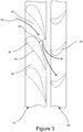
- Figure 3 shows a portion of an axisymmetric cross-section of a high pressure turbine stage of a known gas turbine engine.
- the turbine stage includes a stator vane ring 32 and a rotor ring 34.
- Each vane 36 has a complex aerofoil profile and is shaped to swirl the gas flow from the combustor 16 in the direction of rotation of the rotor ring 34.
- the passageway 50 comprises operational gas washed surfaces over which gas flows during operation of the gas turbine engine.
- the pressure and suction surfaces of each vane 36 provide operational gas washed surfaces 46, with each passageway 50 being delimited by a pressure surface of one vane 36 and a suction surface of an adjacent vane.
- Corresponding portions of the inner endwall 42 and the outer endwall 44 are also operational gas washed surfaces of the respective passageway.
- Each passageway 50 between adjacent vanes 36 has an operational flow area 54, which herein is defined as the minimum cross-sectional area of the passageway 50.
- the operational flow area 54 affects the mass flow rate of gas flowing through the passageway 50, and hence the stator vane ring 32.
- Combustor loading is a parameter corresponding to the stability of combustion based on mass flow rate, pressure and combustor volume.
- the mass flow rate through the combustor 16 is affected by the operational flow area 54 of the passageways 50 of the stator vane ring 32 of the high pressure turbine 17, directly downstream of the combustor 16.
- cold air flows through the passageways 50 in the stator vane ring 32 to the rotor ring 34.
- Figure 4 shows an axisymmetric sectional view of a high pressure turbine stage of a first example gas turbine engine.
- This turbine stage comprises similar features to the turbine stage described with respect to Figures 2 and 3 , with like reference numerals denoting like features.
- each passageway 50 is delimited by operational gas washed surfaces of the respective adjacent vanes 36, and respective portions of the inner endwall 42 and the outer endwall 44.
- the operational gas washed surfaces are those over which gas flows whilst the gas turbine engine is in normal operation following ignition.
- a restrictor 56 provided on the vane 36.
- a restrictor 56 is provided on each vane 36 of the stator vane ring 32.
- a restrictor 56 may only be provided on some of the vanes 36 of the stator vane ring, or may be installed in the passageway between adjacent vanes.
- the restrictor 56 is provided on the operational gas washed surface 46 of the vane 36.
- the restrictor 56 completely covers the operational gas washed surface 46 of the vane 36 so as to extend over both the pressure surface and the suction surface of the vane.
- the restrictor 56 may only cover part of the operational gas washed surface 46, for example over a limited spanwise portion of the vane, over a limited chordwise portion or the vane, on pressure surface only, or on the suction surface only.
- a restrictor may only be provided on the operational gas washed surface 46 of the vane 36 in a downstream region of the passageway 50 proximal to the rotor ring 34, for example from 50% of the chord of the vane to the trailing edge.
- the restrictor provides a temporary gas washed surface 58 for the vane 36.
- each passageway 50 has an operational flow area 54, defined as the minimum cross sectional area of the passageway 50 - the "throat" - (which will generally be in a plane perpendicular to the direction of flow through the passageway 50), between the operational gas washed surfaces, which will generally be towards the downstream end of the passageway where adjacent vanes taper towards each other.
- the restrictor 56 is configured to reduce the operational flow area 54 by at least 50% of the operational flow area 54.
- a gas turbine engine comprising a combustor 16 configured to initiate combustion and a stator vane ring 32 defining a plurality of passageways 50 between adjacent vanes 36.
- a restrictor 56 is provided on an operational gas washed surface 46 of a vane 36, the restrictor 56 defining a temporary gas washed surface 58 of the vane 36.
- the restrictor 56 may be applied to the vane 36 during assembly of the gas turbine engine. Subsequently, the compressor is accelerated by a starting mechanism, for example an auxiliary power unit or starter motor. The compressor drives a flow of cold (ambient) air through the engine. Cold air also flows through the stator vane ring 32, with air flowing over the temporary gas washed surfaces 58 of the vanes 36.
- the restrictor 56 provides a reduction in the operational flow area 54 through the stator vane ring 32, the mass flow rate of the air through the stator vane ring 32 is reduced relative to a configuration of the engine without the restrictor 56.
- the combustor loading is therefore reduced as a result, compared to a configuration of the engine without the restrictor.
- the combustor loading is sufficiently low to enable combustion to be initiated in the combustor 16.
- the combustor loading may be sufficiently low with a lower mass flow rate through the combustor 16 than compared with a configuration of the engine without the restrictor 56.
- a fuel-air mixture is ignited in the combustor 16 and hot gases exit the combustor 16. Once ignition has been achieved, the turbine begins to drive the compressor such that a higher compression ratio and combustor exit temperatures are achieved.
- the restrictor 56 is configured to be ablated from the vanes 36 once combustion has been initiated, such that ablation commences following initiation of combustion (block 130). Ablation may take place once the temperature of the flow of hot gases 52 exiting the combustor 16 reaches a threshold temperature.
- the threshold temperature may be from 200 °C to 600 °C.
- the restrictor 56 may ablate away gradually as the temperature of the hot gases 52 increases.
- the temporary gas washed surface 58 is removed to reveal the operational gas washed surface 46 of the vane 36.
- the passageway 50 therefore regains the original operational flow area 54, allowing a greater mass flow rate through the stator vane ring 32 and consequently allowing the engine to sustain combustion and operate at design (e.g. cruise) conditions.
- the restrictor 56 is provided as a coating on the operational gas washed surface 46 of the vane 36.
- the coating can be applied to the vane 36 during assembly of the gas turbine engine.
- the coating may be applied to the vane 36 using spraying or painting.
- the coating may be formed from a metallic material, in particular a soft metal, such as tin or an alloy of lead and tin. During ablation of the coating, the metal may melt when the temperature of the hot gases 52 exiting the combustor 16 reaches a threshold temperature, which may be from 200 °C to 600 °C.
- a restrictor can be provided as an insert which covers the operational gas washed surface 46 of one or more vanes 36.
- Such an insert may be placed within the passageway 50 during assembly of the gas turbine.
- Each passageway 50 has an inlet and an outlet, with the passageway generally narrowing from the inlet to the outlet.
- the insert may be inserted into the passageway 50 through the inlet (i.e. from the upstream side of the stator vane ring). Due to the narrowing of the passageway 50, the insert may be retained in the outlet such that it is prevented from passing through the outlet.
- the insert may be configured to cooperate with the vane 36 and/or the outlet of the passageway 50 in order to prevent the insert from being ejected from the passageway 50 in a downstream direction when cold air is initially flowing through the engine during start-up.
- the insert may be fixed to the vane 36 or stator vane ring 32 using adhesive or using interlocking elements which cooperate with the vane 36 or outlet of the passageway 50.
- the insert may be formed from a material which is significantly weaker than the material of the stator vane ring, for example, the insert may be formed from a paper-based or card-based material.
- the material may combust when the temperature of the hot gases 52 exiting the combustor reaches a threshold temperature, which may be from 200 °C to 600 °C.
- a threshold temperature which may be from 200 °C to 600 °C.
- Any material having properties that promote ablation in the relevant conditions can be used, for example a coating or insert as disclosed herein may be formed from a plastics material or a wood-based material.
- Figure 6 shows an axisymmetric sectional view of a high pressure turbine stage of a second example gas turbine according to the present disclosure.
- This example comprises similar features to that of the first example as previously described, with like reference numerals indicating like features. It differs from the embodiment of Figure 4 with respect to the form of the restrictor.
- each passageway 50 is delimited by operational gas washed surfaces of the respective adjacent vanes 36, and respective portions of the inner endwall 42 and the outer endwall 44.
- the operational gas washed surfaces are those over which gas flows whilst the gas turbine engine is in normal operation following ignition.
- restrictors 62 provided on the inner and outer endwalls 42, 44 delimiting the passageway 50.
- a restrictor 62 may be provided on only one of the inner and outer endwalls 42, 44.
- a restrictor 62 may only be provided on the inner and outer endwalls 42, 44 of some of the passageways 50 in the stator vane ring 32.
- restrictors 62 may be provided on the inner and outer endwalls 42, 44 of all the passageways 50 in the stator vane ring 32.
- the restrictors 62 completely cover the operational gas washed surface of the inner and outer endwalls 42, 44, but in other examples, a restrictor 62 may only cover part of the operational gas washed surface.
- the restrictor 62 may only be provided on the operational gas washed surface of the passageway 50 in a region of the passageway proximal to the rotor ring 34, that is to say a downstream chord-wise portion of the passageway.
- the restrictor provides a temporary gas washed surface 66 for the inner and outer endwalls 42, 44.
- Figure 7 shows a sectional view of the high pressure turbine stage in a plane intersecting the principal rotational axis of the engine and which intersects a passageway 50 provided with a restrictor 62.
- each passageway 50 has an operational flow area 54, defined as the minimum cross-sectional area of the passageway 50 during normal operation of the gas turbine engine after starting.
- the restrictor 62 may be configured to reduce the operational flow area 54 by at least 50% of the operational flow area 54.
- the restrictor 62 is shaped to reduce the flow area from a maximum at the inlet of the passageway to a minimum at the outlet of the passageway 50.
- the restrictor 62 may also have profile configured to achieve a smooth flow or air and/or gas across the temporary gas washed surface 66 provided by the restrictor 62 (which may be referred to as an "aerodynamic profile").
- the restrictor 62 is also shaped to ensure that air 52 flowing through the stator vane ring 32 has a whirl as it exits the stator vane ring 32 and enters the rotor ring 34 in substantially the same direction as would be the case in a configuration without the restrictor 62 being provided in the passageway 50.
- the whirl is defined as the angle of the flow exiting the stator vane ring 32, relative to the axial centreline of the engine.
- a gas turbine engine comprising a combustor 16 configured to initiate combustion and a stator vane ring 32 defining a plurality of passageways 50 between adjacent vanes 36.
- a restrictor 62 is provided on an operational gas washed surface of an endwall 42, 44, the restrictor 62 defining a temporary gas washed surface 66 of the endwall 42, 44 as described above with respect to Figures 6 and 7 .
- the restrictor 62 may be provided on both the inner and outer endwalls 42, 44.
- the restrictor 62 may be applied to the endwalls 42, 44 during assembly of the gas turbine engine.
- the compressor is accelerated by a starting mechanism, for example an auxiliary power unit or starter motor.
- the compressor drives a flow of cold (ambient) air 52 through the engine.
- the combustor loading is sufficiently low to enable combustion to be initiated in the combustor 16.
- the combustor loading may be sufficiently low with a lower mass flow rate through the combustor 16 than compared with a configuration of the engine without the restrictor 62.
- a fuel-air mixture is ignited in the combustor 16 and hot gases 52 exit the combustor 16. Once ignition has been achieved, the turbine begins to drive the compressor such that a higher compression ratio and combustor exit temperatures are achieved.
- the restrictor 62 is configured to be ablated from the inner and outer endwalls 42, 44, once combustion has been initiated, such that ablation commences following initiation of combustion (block 230). Ablation may take place once the temperature of the flow of hot gases 52 exiting the combustor reaches a threshold temperature.
- the threshold temperature may be from 200 °C to 600 °C.
- the restrictor 62 may ablate away gradually as the temperature of the hot gases 52 increases.
- the temporary gas washed surfaces 66 are removed to reveal the operational gas washed surfaces of the inner and outer endwalls 42, 44.
- the passageway 50 therefore regains the operational flow area 54, allowing a greater mass flow rate through the stator vane ring 32 and consequently allowing the engine to sustain combustion and operate at design (e.g. cruise) conditions.
- the restrictor 62 is provided as an insert which covers the operational gas washed surface of the inner and outer endwalls 42, 44. Such an insert may be placed within the passageway 50 during assembly of the gas turbine engine.
- Each passageway 50 has an inlet and an outlet, with the passageway generally narrowing from the inlet to the outlet.
- the insert may be inserted into the passageway 50 through the inlet (i.e. from the upstream side of the stator vane ring). Due to the narrowing of the passageway 50, the insert may be retained in the outlet such that it is prevented from passing through the outlet.
- the insert may be configured to cooperate with the inner and outer endwalls 42, 44 and/or the vanes 36 and/or the outlet of the passageway 50 in order to prevent the insert from being ejected from the passageway 50 in a downstream direction when cold air is initially flowing through the engine prior to initiation of combustion.
- the insert may be fixed to the inner and outer endwalls 42, 44 or vanes 36 or stator vane ring 32 using adhesive or using interlocking elements which cooperate with the inner and outer endwalls 42, 44 or vanes 36 or outlet of the passageway 50.
- the insert may be formed from a material which is significantly weaker than the material of the stator vane ring, for example, the insert may be formed from a paper-based or card-based material. During ablation of the insert, the material may combust when the temperature of the hot gases 52 exiting the combustor 16 reaches a threshold temperature, which may be from 200 °C to 600 °C.
- the restrictor 62 may be provided as a coating on the operational gas washed surface of the inner and outer endwalls 42, 44.
- the coating can be applied to the inner and outer endwalls 42, 44 during assembly of the gas turbine engine.
- the coating may be applied to the inner and outer endwalls 42, 44 using spraying or painting.
- the coating may be formed from a metallic material, in particular a soft metal, such as tin or an alloy of lead and tin.
- the metal may melt when the temperature of the hot gases 52 exiting the combustor 16 reaches a threshold temperature, which may be from 200 °C to 600 °C.
- a coating or insert as disclosed herein may be formed from a plastics material or a wood-based material.
- the restrictor 56, 62 is provided on a stator vane ring 32 of a high pressure turbine of a gas turbine engine, the restrictor 56, 62 could also be provided on a stator vane ring 32 of a low pressure turbine. Additionally, the restrictor 56, 62 may also be provided on a rotor ring 34 of a high pressure turbine or low pressure turbine.
Landscapes
- Engineering & Computer Science (AREA)
- Mechanical Engineering (AREA)
- General Engineering & Computer Science (AREA)
- Chemical & Material Sciences (AREA)
- Combustion & Propulsion (AREA)
- Materials Engineering (AREA)
- Physics & Mathematics (AREA)
- Fluid Mechanics (AREA)
- Turbine Rotor Nozzle Sealing (AREA)
- Structures Of Non-Positive Displacement Pumps (AREA)
Abstract
Description
- The present disclosure relates to a gas turbine engine and a method of starting a gas turbine engine.
- For some applications, it is a requirement of aircraft gas turbine engines to be started at a variety of in-flight conditions, including at altitude. There can be issues associated with starting such an engine at altitude. In particular, it can be difficult to achieve ignition of fuel within the combustor at altitude. In order to achieve ignition of the fuel, the combustor loading must be sufficiently low. Combustor loading is a parameter used to indicate the stability of combustion based on mass flow rate, pressure and combustor volume. Combustor loading can be reduced by increasing the combustor volume. At altitude, the air pressure is relatively low, therefore the combustor volume needs to be high to achieve a sufficiently low combustor loading to be able to achieve ignition. However, increasing the combustor volume is undesirable as it results in a significant increase in the size and weight of the engine, leading to further fuel and material cost.
- There is therefore a need to develop a gas turbine engine that alleviates at least some of the aforementioned problems or at least to provide a useful alternative.
- The present disclosure provides a gas turbine engine and a method of starting a gas turbine engine as set out in the appended claims.
- According to a first aspect, there is provided a gas turbine engine comprising: a combustor configured to initiate combustion; and a turbine comprising a stator vane ring defining a plurality of passageways between adjacent vanes; wherein at least one of the passageways is provided with a restrictor which defines a temporary gas washed surface for the stator vane ring and is configured to be ablated upon initiation of combustion to reveal an operational gas washed surface of the stator vane ring.
- Ablation includes, but is not limited to, the following: erosion, vaporisation, chipping, burning, and melting.
- It may be that the passageway comprises circumferentially extending endwalls between adjacent vanes. The restrictor may be provided on an operational gas washed surface of the endwalls.
- The restrictor may be provided on the operational gas washed surface of a vane delimiting the passageway.
- The restrictor may be a coating provided on the endwalls. The coating may at least partially cover an operational gas washed surface of the endwalls.
- The restrictor may be a coating provided on a vane delimiting the passageway. The coating may at least partially cover the operational gas washed surface of the respective vane. The coating may completely cover the operational gas washed surface of the respective vane.
- The coating may be formed from tin or an alloy of lead and tin.
- The restrictor may be an insert configured to cooperate with the stator vane to prevent downstream ejection prior to ablation. It may be that each passageway narrows from an inlet to an outlet. It may be that the insert is configured to be received in the inlet and that the outlet is configured to prevent ejection of the insert prior to ablation. The insert may be formed from a paper-based material or a card-based material.
- The passageway may define an operational flow area. The restrictor may be configured to restrict the operational flow area by at least 50% of the operational flow area.
- It may be that the restrictor is configured to commence ablation when the combustor exit temperature is from 200 °C to 600 °C.
- According to a second aspect, there is provided a method of starting a gas turbine engine, the method comprising the steps of: providing a gas turbine engine comprising a combustor configured to initiate combustion and a turbine comprising a stator vane ring defining a plurality of passageways between adjacent vanes; providing at least one of the passageways with a restrictor defining a temporary gas washed surface for the stator vane ring; and initiating combustion in the combustor to increase the temperature of flow exiting the combustor and thereby ablating the restrictor to reveal an operational gas washed surface of the stator vane ring.
- The restrictor may be a coating. It may be that providing at least one of the passageways with the restrictor comprises applying the coating to an operational gas washed surface of the stator vane ring. The coating may be applied by spraying or painting.
- The restrictor may be an insert. It may be that providing at least one of the passageways with the restrictor comprises installing the insert in the stator vane ring to cover an operational gas washed surface of the stator vane ring. The insert may be formed from a paper-based material or a card-based material.
- The restrictor may be provided on an operational gas washed surface of a vane delimiting the passageway.
- The restrictor may be provided on an operational gas washed surface of an endwall, the endwall circumferentially extending between adjacent vanes.
- The skilled person will appreciate that except where mutually exclusive, a feature or parameter described in relation to any one of the above aspects may be applied to any other aspect. Furthermore, except where mutually exclusive, any feature or parameter described herein may be applied to any aspect and/or combined with any other feature or parameter described herein.
- Embodiments will now be described by way of example only, with reference to the Figures, in which:
-
Figure 1 is a sectional side view of a gas turbine engine; -
Figure 2 is a front view of a known stator vane ring; -
Figure 3 shows a turbine stage of a known gas turbine engine; -
Figure 4 shows a turbine stage according to a first example gas turbine engine; -
Figure 5 is a flowchart showing a method of starting the gas turbine engine ofFigure 4 ; -
Figure 6 shows a turbine stage according to a second example gas turbine engine; -
Figure 7 is a side view of the turbine stage according toFigure 6 ; and -
Figure 8 is a flowchart showing a method of starting the gas turbine engine ofFigures 6 and7 . - Aspects and embodiments of the present disclosure will now be discussed with reference to the accompanying figures. Further aspects and embodiments will be apparent to those skilled in the art.
- With reference to
Figure 1 , a gas turbine engine is generally indicated at 10, having a principal androtational axis 11. Theengine 10 comprises, in axial flow series, anair intake 12, apropulsive fan 13, anintermediate pressure compressor 14, a high-pressure compressor 15, acombustor 16, a high-pressure turbine 17, anintermediate pressure turbine 18, a low-pressure turbine 19 and anexhaust nozzle 20. Anacelle 21 generally surrounds theengine 10 and defines both theintake 12 and theexhaust nozzle 20. - The
gas turbine engine 10 works in the conventional manner so that air entering theintake 12 is accelerated by thefan 13 to produce two air flows: a first air flow into theintermediate pressure compressor 14 and a second air flow which passes through abypass duct 22 to provide propulsive thrust. Theintermediate pressure compressor 14 compresses the air flow directed into it before delivering that air to thehigh pressure compressor 15 where further compression takes place. - The compressed air exhausted from the high-
pressure compressor 15 is directed into thecombustor 16 where it is mixed with fuel and the mixture combusted. The resultant hot combustion products then expand through, and thereby drive the high, intermediate and low-pressure turbines nozzle 20 to provide additional propulsive thrust. The high 17, intermediate 18 and low 19 pressure turbines drive respectively thehigh pressure compressor 15,intermediate pressure compressor 14 andfan 13, each by suitable interconnecting shaft. - The
high pressure turbine 17 comprises a stator vane ring 32 (Figure 2 ) and a rotor ring 34 (Figure 3 ), downstream of thestator vane ring 32. -
Figure 2 shows a known examplestator vane ring 32. Thestator vane ring 32 comprises a plurality ofvanes 36 circumferentially mounted around a central axis. In this example, thevanes 36 are mounted between aninner ring 38 and anouter ring 40 of thestator vane ring 32. The radially outer surface of theinner ring 38 defines aninner endwall 42. The radially inner surface of theouter ring 40 defines anouter endwall 44. - There is a plurality of
passageways 50 betweenadjacent vanes 36 in thestator vane ring 32. Eachpassageway 50 is delimited by theadjacent vanes 36, the inner endwall 42 and theouter endwall 44. Thepassageways 50 allow flow exiting thecombustor 16, to flow downstream through thestator vane ring 32 to therotor ring 34. Therotor ring 34 comprises a plurality ofturbine blades 48 configured to rotate around the central axis. -
Figure 3 shows a portion of an axisymmetric cross-section of a high pressure turbine stage of a known gas turbine engine. The turbine stage includes astator vane ring 32 and arotor ring 34. Eachvane 36 has a complex aerofoil profile and is shaped to swirl the gas flow from thecombustor 16 in the direction of rotation of therotor ring 34. Thepassageway 50 comprises operational gas washed surfaces over which gas flows during operation of the gas turbine engine. The pressure and suction surfaces of eachvane 36 provide operational gas washed surfaces 46, with eachpassageway 50 being delimited by a pressure surface of onevane 36 and a suction surface of an adjacent vane. Corresponding portions of the inner endwall 42 and theouter endwall 44 are also operational gas washed surfaces of the respective passageway. - Each
passageway 50 betweenadjacent vanes 36 has anoperational flow area 54, which herein is defined as the minimum cross-sectional area of thepassageway 50. Theoperational flow area 54 affects the mass flow rate of gas flowing through thepassageway 50, and hence thestator vane ring 32. - As discussed above, in order to initiate combustion, the combustor loading must be sufficiently low. Combustor loading is a parameter corresponding to the stability of combustion based on mass flow rate, pressure and combustor volume. The mass flow rate through the
combustor 16 is affected by theoperational flow area 54 of thepassageways 50 of thestator vane ring 32 of thehigh pressure turbine 17, directly downstream of thecombustor 16. Prior to initiation of combustion in thecombustor 16, cold air flows through thepassageways 50 in thestator vane ring 32 to therotor ring 34. Once conditions for combustion have been achieved, fuel and air combust in thecombustor 16, after whichhot gases 52 are produced and flow through thepassageways 50 in thestator vane ring 32, driving thehigh pressure turbine 17. -
Figure 4 shows an axisymmetric sectional view of a high pressure turbine stage of a first example gas turbine engine. This turbine stage comprises similar features to the turbine stage described with respect toFigures 2 and3 , with like reference numerals denoting like features. - As described above, each
passageway 50 is delimited by operational gas washed surfaces of the respectiveadjacent vanes 36, and respective portions of the inner endwall 42 and theouter endwall 44. - The operational gas washed surfaces are those over which gas flows whilst the gas turbine engine is in normal operation following ignition.
- As shown in
Figure 4 , there is a restrictor 56 provided on thevane 36. In this particular example, arestrictor 56 is provided on eachvane 36 of thestator vane ring 32. In other examples, a restrictor 56 may only be provided on some of thevanes 36 of the stator vane ring, or may be installed in the passageway between adjacent vanes. The restrictor 56 is provided on the operational gas washedsurface 46 of thevane 36. In this example, the restrictor 56 completely covers the operational gas washedsurface 46 of thevane 36 so as to extend over both the pressure surface and the suction surface of the vane. In variants of this example, the restrictor 56 may only cover part of the operational gas washedsurface 46, for example over a limited spanwise portion of the vane, over a limited chordwise portion or the vane, on pressure surface only, or on the suction surface only. For example, a restrictor may only be provided on the operational gas washedsurface 46 of thevane 36 in a downstream region of thepassageway 50 proximal to therotor ring 34, for example from 50% of the chord of the vane to the trailing edge. The restrictor provides a temporary gas washedsurface 58 for thevane 36. - As discussed previously with reference to
Figure 3 , eachpassageway 50 has anoperational flow area 54, defined as the minimum cross sectional area of the passageway 50 - the "throat" - (which will generally be in a plane perpendicular to the direction of flow through the passageway 50), between the operational gas washed surfaces, which will generally be towards the downstream end of the passageway where adjacent vanes taper towards each other. By providing a restrictor 56 onadjacent vanes 36, the effectiveoperational flow area 54 is reduced and atemporary flow area 60 is defined. In examples, therestrictor 56 is configured to reduce theoperational flow area 54 by at least 50% of theoperational flow area 54. - An example method of starting the gas turbine engine will now be described with respect to
Figure 5 and with reference to the turbine stage described about with respect toFigure 4 . Inblock 100, a gas turbine engine is provided comprising acombustor 16 configured to initiate combustion and astator vane ring 32 defining a plurality ofpassageways 50 betweenadjacent vanes 36. - In
block 110, arestrictor 56 is provided on an operational gas washedsurface 46 of avane 36, the restrictor 56 defining a temporary gas washedsurface 58 of thevane 36. The restrictor 56 may be applied to thevane 36 during assembly of the gas turbine engine. Subsequently, the compressor is accelerated by a starting mechanism, for example an auxiliary power unit or starter motor. The compressor drives a flow of cold (ambient) air through the engine. Cold air also flows through thestator vane ring 32, with air flowing over the temporary gas washed surfaces 58 of thevanes 36. As the restrictor 56 provides a reduction in theoperational flow area 54 through thestator vane ring 32, the mass flow rate of the air through thestator vane ring 32 is reduced relative to a configuration of the engine without therestrictor 56. The combustor loading is therefore reduced as a result, compared to a configuration of the engine without the restrictor. - With reference to block 120, the combustor loading is sufficiently low to enable combustion to be initiated in the
combustor 16. The combustor loading may be sufficiently low with a lower mass flow rate through thecombustor 16 than compared with a configuration of the engine without therestrictor 56. A fuel-air mixture is ignited in thecombustor 16 and hot gases exit thecombustor 16. Once ignition has been achieved, the turbine begins to drive the compressor such that a higher compression ratio and combustor exit temperatures are achieved. - The restrictor 56 is configured to be ablated from the
vanes 36 once combustion has been initiated, such that ablation commences following initiation of combustion (block 130). Ablation may take place once the temperature of the flow ofhot gases 52 exiting thecombustor 16 reaches a threshold temperature. For example, the threshold temperature may be from 200 °C to 600 °C. The restrictor 56 may ablate away gradually as the temperature of thehot gases 52 increases. - As the restrictor 56 has been ablated from the
vane 36, the temporary gas washedsurface 58 is removed to reveal the operational gas washedsurface 46 of thevane 36. Thepassageway 50 therefore regains the originaloperational flow area 54, allowing a greater mass flow rate through thestator vane ring 32 and consequently allowing the engine to sustain combustion and operate at design (e.g. cruise) conditions. - The restrictor 56 is provided as a coating on the operational gas washed
surface 46 of thevane 36. The coating can be applied to thevane 36 during assembly of the gas turbine engine. The coating may be applied to thevane 36 using spraying or painting. The coating may be formed from a metallic material, in particular a soft metal, such as tin or an alloy of lead and tin. During ablation of the coating, the metal may melt when the temperature of thehot gases 52 exiting thecombustor 16 reaches a threshold temperature, which may be from 200 °C to 600 °C. - Alternatively, a restrictor can be provided as an insert which covers the operational gas washed
surface 46 of one ormore vanes 36. Such an insert may be placed within thepassageway 50 during assembly of the gas turbine. Eachpassageway 50 has an inlet and an outlet, with the passageway generally narrowing from the inlet to the outlet. During assembly, the insert may be inserted into thepassageway 50 through the inlet (i.e. from the upstream side of the stator vane ring). Due to the narrowing of thepassageway 50, the insert may be retained in the outlet such that it is prevented from passing through the outlet. The insert may be configured to cooperate with thevane 36 and/or the outlet of thepassageway 50 in order to prevent the insert from being ejected from thepassageway 50 in a downstream direction when cold air is initially flowing through the engine during start-up. The insert may be fixed to thevane 36 orstator vane ring 32 using adhesive or using interlocking elements which cooperate with thevane 36 or outlet of thepassageway 50. The insert may be formed from a material which is significantly weaker than the material of the stator vane ring, for example, the insert may be formed from a paper-based or card-based material. During ablation of the insert, the material may combust when the temperature of thehot gases 52 exiting the combustor reaches a threshold temperature, which may be from 200 °C to 600 °C. Any material having properties that promote ablation in the relevant conditions can be used, for example a coating or insert as disclosed herein may be formed from a plastics material or a wood-based material. -
Figure 6 shows an axisymmetric sectional view of a high pressure turbine stage of a second example gas turbine according to the present disclosure. This example comprises similar features to that of the first example as previously described, with like reference numerals indicating like features. It differs from the embodiment ofFigure 4 with respect to the form of the restrictor. - As described above, each
passageway 50 is delimited by operational gas washed surfaces of the respectiveadjacent vanes 36, and respective portions of the inner endwall 42 and theouter endwall 44. The operational gas washed surfaces are those over which gas flows whilst the gas turbine engine is in normal operation following ignition. - In this example, there are restrictors 62 provided on the inner and
outer endwalls passageway 50. In other examples, a restrictor 62 may be provided on only one of the inner andouter endwalls outer endwalls passageways 50 in thestator vane ring 32. In other examples,restrictors 62 may be provided on the inner andouter endwalls passageways 50 in thestator vane ring 32. In the illustrated example, therestrictors 62 completely cover the operational gas washed surface of the inner andouter endwalls passageway 50 in a region of the passageway proximal to therotor ring 34, that is to say a downstream chord-wise portion of the passageway. The restrictor provides a temporary gas washedsurface 66 for the inner andouter endwalls -
Figure 7 shows a sectional view of the high pressure turbine stage in a plane intersecting the principal rotational axis of the engine and which intersects apassageway 50 provided with arestrictor 62. As discussed previously, with reference toFig. 3 , eachpassageway 50 has anoperational flow area 54, defined as the minimum cross-sectional area of thepassageway 50 during normal operation of the gas turbine engine after starting. By providingrestrictors 62 on the inner andouter endwalls passageway 50, the effectiveoperational flow area 54 is reduced to atemporary flow area 64. The restrictor 62 may be configured to reduce theoperational flow area 54 by at least 50% of theoperational flow area 54. - The restrictor 62 is shaped to reduce the flow area from a maximum at the inlet of the passageway to a minimum at the outlet of the
passageway 50. The restrictor 62 may also have profile configured to achieve a smooth flow or air and/or gas across the temporary gas washedsurface 66 provided by the restrictor 62 (which may be referred to as an "aerodynamic profile"). The restrictor 62 is also shaped to ensure thatair 52 flowing through thestator vane ring 32 has a whirl as it exits thestator vane ring 32 and enters therotor ring 34 in substantially the same direction as would be the case in a configuration without the restrictor 62 being provided in thepassageway 50. The whirl is defined as the angle of the flow exiting thestator vane ring 32, relative to the axial centreline of the engine. - An example method of starting the gas turbine engine will now be described with respect to
Figure 8 and with reference to the turbine stage described about with respect toFigures 6 and7 . - In
block 200, a gas turbine engine is provided comprising acombustor 16 configured to initiate combustion and astator vane ring 32 defining a plurality ofpassageways 50 betweenadjacent vanes 36. - In
block 210, arestrictor 62 is provided on an operational gas washed surface of anendwall surface 66 of theendwall Figures 6 and7 . The restrictor 62 may be provided on both the inner andouter endwalls endwalls air 52 through the engine. Cold air also flows through thestator vane ring 32, with air flowing over the temporary gas washed surfaces 66 of the inner andouter endwalls operational flow area 54 through thestator vane ring 32, the mass flow rate of the air through thestator vane ring 32 is reduced relative to a configuration of the engine without therestrictor 62. The combustor loading is therefore reduced as a result compared to a configuration of the engine without therestrictor 62. - With reference to block 220, the combustor loading is sufficiently low to enable combustion to be initiated in the
combustor 16. The combustor loading may be sufficiently low with a lower mass flow rate through thecombustor 16 than compared with a configuration of the engine without therestrictor 62. A fuel-air mixture is ignited in thecombustor 16 andhot gases 52 exit thecombustor 16. Once ignition has been achieved, the turbine begins to drive the compressor such that a higher compression ratio and combustor exit temperatures are achieved. - The restrictor 62 is configured to be ablated from the inner and
outer endwalls hot gases 52 exiting the combustor reaches a threshold temperature. For example, the threshold temperature may be from 200 °C to 600 °C. The restrictor 62 may ablate away gradually as the temperature of thehot gases 52 increases. - As the restrictor 62 has been ablated from the inner and
outer endwalls outer endwalls passageway 50 therefore regains theoperational flow area 54, allowing a greater mass flow rate through thestator vane ring 32 and consequently allowing the engine to sustain combustion and operate at design (e.g. cruise) conditions. - The restrictor 62 is provided as an insert which covers the operational gas washed surface of the inner and
outer endwalls passageway 50 during assembly of the gas turbine engine. Eachpassageway 50 has an inlet and an outlet, with the passageway generally narrowing from the inlet to the outlet. During assembly, the insert may be inserted into thepassageway 50 through the inlet (i.e. from the upstream side of the stator vane ring). Due to the narrowing of thepassageway 50, the insert may be retained in the outlet such that it is prevented from passing through the outlet. The insert may be configured to cooperate with the inner andouter endwalls vanes 36 and/or the outlet of thepassageway 50 in order to prevent the insert from being ejected from thepassageway 50 in a downstream direction when cold air is initially flowing through the engine prior to initiation of combustion. The insert may be fixed to the inner andouter endwalls vanes 36 orstator vane ring 32 using adhesive or using interlocking elements which cooperate with the inner andouter endwalls vanes 36 or outlet of thepassageway 50. The insert may be formed from a material which is significantly weaker than the material of the stator vane ring, for example, the insert may be formed from a paper-based or card-based material. During ablation of the insert, the material may combust when the temperature of thehot gases 52 exiting thecombustor 16 reaches a threshold temperature, which may be from 200 °C to 600 °C. - Alternatively, the restrictor 62 may be provided as a coating on the operational gas washed surface of the inner and
outer endwalls outer endwalls outer endwalls hot gases 52 exiting thecombustor 16 reaches a threshold temperature, which may be from 200 °C to 600 °C. As described previously, any material having properties that promote ablation in the relevant conditions can be used, for example a coating or insert as disclosed herein may be formed from a plastics material or a wood-based material. - Whilst it has been described herein that the restrictor 56, 62 is provided on a
stator vane ring 32 of a high pressure turbine of a gas turbine engine, the restrictor 56, 62 could also be provided on astator vane ring 32 of a low pressure turbine. Additionally, the restrictor 56, 62 may also be provided on arotor ring 34 of a high pressure turbine or low pressure turbine. - It will be understood that the invention is not limited to the embodiments above-described and various modifications and improvements can be made without departing from the concepts described herein within the scope of the following claims.
Claims (15)
- A gas turbine engine (10) comprising:a combustor (16) configured to initiate combustion; anda turbine (17) comprising a stator vane ring (32) defining a plurality of passageways (50) between adjacent vanes (36);wherein at least one of the passageways (50) is provided with a restrictor (56) which defines a temporary gas washed surface (58) for the stator vane ring and is configured to be ablated upon initiation of combustion to reveal an operational gas washed surface (46) of the stator vane ring.
- The gas turbine engine according to Claim 1, wherein the passageway (50) comprises circumferentially extending endwalls between adjacent vanes; and wherein the restrictor (56) is provided on an operational gas washed surface of the endwalls.
- The gas turbine engine according to Claim 1 or 2, wherein the restrictor (56) is provided on the operational gas washed surface of a vane delimiting the passageway.
- The gas turbine engine according to any one of Claims 1 to 3, wherein the restrictor (56) is a coating provided on the endwalls, and wherein the coating at least partially covers an operational gas washed surface of the endwalls.
- The gas turbine engine according to Claim 3 or 4, wherein the restrictor (56) is a coating provided on a vane delimiting the passageway and wherein the coating at least partially covers the operational gas washed surface of the respective vane.
- The gas turbine engine according to Claim 5, wherein the coating completely covers the operational gas washed surface of the respective vane.
- The gas turbine according to any one of Claims 4 to 6, wherein the coating is formed from tin or an alloy of lead and tin.
- The gas turbine engine according to any one of Claims 1 to 3, wherein the restrictor (56) is an insert configured to cooperate with the stator vane to prevent downstream ejection of the restrictor prior to ablation.
- The gas turbine engine according to Claim 8, wherein the insert is formed from a paper-based material or a card-based material.
- The gas turbine engine according to any one of Claims 8 to 9, wherein each passageway (50) narrows from an inlet to an outlet, and wherein the insert is configured to be received in the inlet, and wherein the outlet is configured to prevent ejection of the insert prior to ablation.
- The gas turbine engine according to any one of Claims 1 to 10, wherein the passageway (50) defines an operational flow area, and wherein the restrictor (56) is configured to restrict the operational flow area by at least 50% of the operational flow area.
- The gas turbine engine according to any one of Claims 1 to 11, wherein the restrictor (56) is configured to commence ablation when the combustor exit temperature is from 200 °C to 600 °C.
- A method of starting a gas turbine engine (10), the method comprising the steps of:providing a gas turbine engine (10) comprising a combustor (16) configured to initiate combustion and a turbine (17) comprising a stator vane ring (32) defining a plurality of passageways (50) between adjacent vanes (36);providing at least one of the passageways with a restrictor (56) defining a temporary gas washed surface (58) for the stator vane ring (32); andinitiating combustion in the combustor (16) to increase the temperature of flow exiting the combustor, thereby ablating the restrictor (56) to reveal an operational gas washed surface (46) of the stator vane ring (32).
- The method according to Claim 13, wherein the restrictor (56) is an insert, and wherein providing at least one of the passageways (50) with the restrictor comprises installing the insert in the stator vane ring (32) to cover an operational gas washed surface of the stator vane ring.
- The method according to Claims 13 or 14, wherein the restrictor (56) is provided on an operational gas washed surface (46) of an endwall, the endwall circumferentially extending between adjacent vanes.
Applications Claiming Priority (1)
| Application Number | Priority Date | Filing Date | Title |
|---|---|---|---|
| GB201913379A GB201913379D0 (en) | 2019-09-17 | 2019-09-17 | A gas turbine engine |
Publications (2)
| Publication Number | Publication Date |
|---|---|
| EP3795802A1 true EP3795802A1 (en) | 2021-03-24 |
| EP3795802B1 EP3795802B1 (en) | 2023-05-31 |
Family
ID=68315364
Family Applications (1)
| Application Number | Title | Priority Date | Filing Date |
|---|---|---|---|
| EP20192299.4A Active EP3795802B1 (en) | 2019-09-17 | 2020-08-24 | A gas turbine engine |
Country Status (3)
| Country | Link |
|---|---|
| US (1) | US11448087B2 (en) |
| EP (1) | EP3795802B1 (en) |
| GB (1) | GB201913379D0 (en) |
Families Citing this family (1)
| Publication number | Priority date | Publication date | Assignee | Title |
|---|---|---|---|---|
| US12006846B2 (en) * | 2017-11-02 | 2024-06-11 | MTU Aero Engines AG | Additively manufactured intermediate duct for disposition between a low-pressure compressor and a high-pressure compressor, and corresponding manufacturing method |
Citations (4)
| Publication number | Priority date | Publication date | Assignee | Title |
|---|---|---|---|---|
| EP2230381A2 (en) * | 2009-03-18 | 2010-09-22 | General Electric Company | Method of using and reconstructing a film-cooling augmentation device for a turbine airfoil |
| WO2013186756A1 (en) * | 2012-06-14 | 2013-12-19 | Avio S.P.A. | Aerofoil array for a gas turbine with anti fluttering means |
| EP2778343A1 (en) * | 2013-03-12 | 2014-09-17 | Pratt & Whitney Canada Corp. | Compressor stator |
| US20170226860A1 (en) * | 2016-02-05 | 2017-08-10 | MTU Aero Engines AG | Repair method for turbine blades |
Family Cites Families (2)
| Publication number | Priority date | Publication date | Assignee | Title |
|---|---|---|---|---|
| EP2216509A1 (en) * | 2009-02-04 | 2010-08-11 | Siemens Aktiengesellschaft | Turbine component with easily removable protective layer, turbine component set, a turbine and method for protecting a turbine component |
| US11143042B2 (en) * | 2014-02-11 | 2021-10-12 | Raytheon Technologies Corporation | System and method for applying a metallic coating |
-
2019
- 2019-09-17 GB GB201913379A patent/GB201913379D0/en not_active Ceased
-
2020
- 2020-08-24 EP EP20192299.4A patent/EP3795802B1/en active Active
- 2020-08-27 US US17/004,601 patent/US11448087B2/en active Active
Patent Citations (4)
| Publication number | Priority date | Publication date | Assignee | Title |
|---|---|---|---|---|
| EP2230381A2 (en) * | 2009-03-18 | 2010-09-22 | General Electric Company | Method of using and reconstructing a film-cooling augmentation device for a turbine airfoil |
| WO2013186756A1 (en) * | 2012-06-14 | 2013-12-19 | Avio S.P.A. | Aerofoil array for a gas turbine with anti fluttering means |
| EP2778343A1 (en) * | 2013-03-12 | 2014-09-17 | Pratt & Whitney Canada Corp. | Compressor stator |
| US20170226860A1 (en) * | 2016-02-05 | 2017-08-10 | MTU Aero Engines AG | Repair method for turbine blades |
Also Published As
| Publication number | Publication date |
|---|---|
| EP3795802B1 (en) | 2023-05-31 |
| US11448087B2 (en) | 2022-09-20 |
| US20210079807A1 (en) | 2021-03-18 |
| GB201913379D0 (en) | 2019-10-30 |
Similar Documents
| Publication | Publication Date | Title |
|---|---|---|
| EP2815096B1 (en) | Gas turbine engine component with converging/diverging cooling passage | |
| US9482100B2 (en) | Multi-lobed cooling hole | |
| US8157514B2 (en) | Components for gas turbine engines | |
| EP2828485B1 (en) | Component for a gas turbine engine | |
| US10323522B2 (en) | Gas turbine engine component with diffusive cooling hole | |
| EP3090126B1 (en) | Gas turbine engine component comprising endwall countouring trench | |
| US7334985B2 (en) | Shroud with aero-effective cooling | |
| EP2815078A1 (en) | Gas turbine engine component with impingement and lobed cooling hole | |
| US11118466B2 (en) | Compressor stator with leading edge fillet | |
| EP3156597A1 (en) | Cooling holes of turbine | |
| US20200277868A1 (en) | Combustion liner and gas turbine engine comprising a combustion liner | |
| US11448087B2 (en) | Gas turbine engine | |
| EP3045663B1 (en) | Integrally bladed fan rotor with pressure side thickness on blade traing edge | |
| EP3473841B1 (en) | Turbofan engine | |
| US12540551B1 (en) | Gas turbine engines including splittered airfoils | |
| US12018838B2 (en) | Cowl assembly for a gas turbine engine | |
| EP4685339A1 (en) | Cantilever stator vane | |
| US11639666B2 (en) | Stator with depressions in gaspath wall adjacent leading edges | |
| US10677070B2 (en) | Blade platform gusset with internal cooling |
Legal Events
| Date | Code | Title | Description |
|---|---|---|---|
| PUAI | Public reference made under article 153(3) epc to a published international application that has entered the european phase |
Free format text: ORIGINAL CODE: 0009012 |
|
| STAA | Information on the status of an ep patent application or granted ep patent |
Free format text: STATUS: THE APPLICATION HAS BEEN PUBLISHED |
|
| AK | Designated contracting states |
Kind code of ref document: A1 Designated state(s): AL AT BE BG CH CY CZ DE DK EE ES FI FR GB GR HR HU IE IS IT LI LT LU LV MC MK MT NL NO PL PT RO RS SE SI SK SM TR |
|
| AX | Request for extension of the european patent |
Extension state: BA ME |
|
| STAA | Information on the status of an ep patent application or granted ep patent |
Free format text: STATUS: REQUEST FOR EXAMINATION WAS MADE |
|
| 17P | Request for examination filed |
Effective date: 20210923 |
|
| RBV | Designated contracting states (corrected) |
Designated state(s): AL AT BE BG CH CY CZ DE DK EE ES FI FR GB GR HR HU IE IS IT LI LT LU LV MC MK MT NL NO PL PT RO RS SE SI SK SM TR |
|
| GRAP | Despatch of communication of intention to grant a patent |
Free format text: ORIGINAL CODE: EPIDOSNIGR1 |
|
| STAA | Information on the status of an ep patent application or granted ep patent |
Free format text: STATUS: GRANT OF PATENT IS INTENDED |
|
| INTG | Intention to grant announced |
Effective date: 20230309 |
|
| GRAS | Grant fee paid |
Free format text: ORIGINAL CODE: EPIDOSNIGR3 |
|
| GRAA | (expected) grant |
Free format text: ORIGINAL CODE: 0009210 |
|
| STAA | Information on the status of an ep patent application or granted ep patent |
Free format text: STATUS: THE PATENT HAS BEEN GRANTED |
|
| AK | Designated contracting states |
Kind code of ref document: B1 Designated state(s): AL AT BE BG CH CY CZ DE DK EE ES FI FR GB GR HR HU IE IS IT LI LT LU LV MC MK MT NL NO PL PT RO RS SE SI SK SM TR |
|
| REG | Reference to a national code |
Ref country code: GB Ref legal event code: FG4D Ref country code: CH Ref legal event code: EP |
|
| REG | Reference to a national code |
Ref country code: AT Ref legal event code: REF Ref document number: 1571025 Country of ref document: AT Kind code of ref document: T Effective date: 20230615 Ref country code: DE Ref legal event code: R096 Ref document number: 602020011276 Country of ref document: DE |
|
| REG | Reference to a national code |
Ref country code: IE Ref legal event code: FG4D |
|
| P01 | Opt-out of the competence of the unified patent court (upc) registered |
Effective date: 20230528 |
|
| REG | Reference to a national code |
Ref country code: LT Ref legal event code: MG9D |
|
| REG | Reference to a national code |
Ref country code: NL Ref legal event code: MP Effective date: 20230531 |
|
| REG | Reference to a national code |
Ref country code: AT Ref legal event code: MK05 Ref document number: 1571025 Country of ref document: AT Kind code of ref document: T Effective date: 20230531 |
|
| PG25 | Lapsed in a contracting state [announced via postgrant information from national office to epo] |
Ref country code: SE Free format text: LAPSE BECAUSE OF FAILURE TO SUBMIT A TRANSLATION OF THE DESCRIPTION OR TO PAY THE FEE WITHIN THE PRESCRIBED TIME-LIMIT Effective date: 20230531 Ref country code: NO Free format text: LAPSE BECAUSE OF FAILURE TO SUBMIT A TRANSLATION OF THE DESCRIPTION OR TO PAY THE FEE WITHIN THE PRESCRIBED TIME-LIMIT Effective date: 20230831 Ref country code: ES Free format text: LAPSE BECAUSE OF FAILURE TO SUBMIT A TRANSLATION OF THE DESCRIPTION OR TO PAY THE FEE WITHIN THE PRESCRIBED TIME-LIMIT Effective date: 20230531 Ref country code: AT Free format text: LAPSE BECAUSE OF FAILURE TO SUBMIT A TRANSLATION OF THE DESCRIPTION OR TO PAY THE FEE WITHIN THE PRESCRIBED TIME-LIMIT Effective date: 20230531 |
|
| PG25 | Lapsed in a contracting state [announced via postgrant information from national office to epo] |
Ref country code: RS Free format text: LAPSE BECAUSE OF FAILURE TO SUBMIT A TRANSLATION OF THE DESCRIPTION OR TO PAY THE FEE WITHIN THE PRESCRIBED TIME-LIMIT Effective date: 20230531 Ref country code: PL Free format text: LAPSE BECAUSE OF FAILURE TO SUBMIT A TRANSLATION OF THE DESCRIPTION OR TO PAY THE FEE WITHIN THE PRESCRIBED TIME-LIMIT Effective date: 20230531 Ref country code: NL Free format text: LAPSE BECAUSE OF FAILURE TO SUBMIT A TRANSLATION OF THE DESCRIPTION OR TO PAY THE FEE WITHIN THE PRESCRIBED TIME-LIMIT Effective date: 20230531 Ref country code: LV Free format text: LAPSE BECAUSE OF FAILURE TO SUBMIT A TRANSLATION OF THE DESCRIPTION OR TO PAY THE FEE WITHIN THE PRESCRIBED TIME-LIMIT Effective date: 20230531 Ref country code: LT Free format text: LAPSE BECAUSE OF FAILURE TO SUBMIT A TRANSLATION OF THE DESCRIPTION OR TO PAY THE FEE WITHIN THE PRESCRIBED TIME-LIMIT Effective date: 20230531 Ref country code: IS Free format text: LAPSE BECAUSE OF FAILURE TO SUBMIT A TRANSLATION OF THE DESCRIPTION OR TO PAY THE FEE WITHIN THE PRESCRIBED TIME-LIMIT Effective date: 20230930 Ref country code: HR Free format text: LAPSE BECAUSE OF FAILURE TO SUBMIT A TRANSLATION OF THE DESCRIPTION OR TO PAY THE FEE WITHIN THE PRESCRIBED TIME-LIMIT Effective date: 20230531 Ref country code: GR Free format text: LAPSE BECAUSE OF FAILURE TO SUBMIT A TRANSLATION OF THE DESCRIPTION OR TO PAY THE FEE WITHIN THE PRESCRIBED TIME-LIMIT Effective date: 20230901 |
|
| PG25 | Lapsed in a contracting state [announced via postgrant information from national office to epo] |
Ref country code: FI Free format text: LAPSE BECAUSE OF FAILURE TO SUBMIT A TRANSLATION OF THE DESCRIPTION OR TO PAY THE FEE WITHIN THE PRESCRIBED TIME-LIMIT Effective date: 20230531 |
|
| PG25 | Lapsed in a contracting state [announced via postgrant information from national office to epo] |
Ref country code: SK Free format text: LAPSE BECAUSE OF FAILURE TO SUBMIT A TRANSLATION OF THE DESCRIPTION OR TO PAY THE FEE WITHIN THE PRESCRIBED TIME-LIMIT Effective date: 20230531 |
|
| PG25 | Lapsed in a contracting state [announced via postgrant information from national office to epo] |
Ref country code: SM Free format text: LAPSE BECAUSE OF FAILURE TO SUBMIT A TRANSLATION OF THE DESCRIPTION OR TO PAY THE FEE WITHIN THE PRESCRIBED TIME-LIMIT Effective date: 20230531 Ref country code: SK Free format text: LAPSE BECAUSE OF FAILURE TO SUBMIT A TRANSLATION OF THE DESCRIPTION OR TO PAY THE FEE WITHIN THE PRESCRIBED TIME-LIMIT Effective date: 20230531 Ref country code: RO Free format text: LAPSE BECAUSE OF FAILURE TO SUBMIT A TRANSLATION OF THE DESCRIPTION OR TO PAY THE FEE WITHIN THE PRESCRIBED TIME-LIMIT Effective date: 20230531 Ref country code: PT Free format text: LAPSE BECAUSE OF FAILURE TO SUBMIT A TRANSLATION OF THE DESCRIPTION OR TO PAY THE FEE WITHIN THE PRESCRIBED TIME-LIMIT Effective date: 20231002 Ref country code: EE Free format text: LAPSE BECAUSE OF FAILURE TO SUBMIT A TRANSLATION OF THE DESCRIPTION OR TO PAY THE FEE WITHIN THE PRESCRIBED TIME-LIMIT Effective date: 20230531 Ref country code: DK Free format text: LAPSE BECAUSE OF FAILURE TO SUBMIT A TRANSLATION OF THE DESCRIPTION OR TO PAY THE FEE WITHIN THE PRESCRIBED TIME-LIMIT Effective date: 20230531 Ref country code: CZ Free format text: LAPSE BECAUSE OF FAILURE TO SUBMIT A TRANSLATION OF THE DESCRIPTION OR TO PAY THE FEE WITHIN THE PRESCRIBED TIME-LIMIT Effective date: 20230531 |
|
| REG | Reference to a national code |
Ref country code: DE Ref legal event code: R097 Ref document number: 602020011276 Country of ref document: DE |
|
| PG25 | Lapsed in a contracting state [announced via postgrant information from national office to epo] |
Ref country code: MC Free format text: LAPSE BECAUSE OF FAILURE TO SUBMIT A TRANSLATION OF THE DESCRIPTION OR TO PAY THE FEE WITHIN THE PRESCRIBED TIME-LIMIT Effective date: 20230531 |
|
| REG | Reference to a national code |
Ref country code: CH Ref legal event code: PL |
|
| PG25 | Lapsed in a contracting state [announced via postgrant information from national office to epo] |
Ref country code: MC Free format text: LAPSE BECAUSE OF FAILURE TO SUBMIT A TRANSLATION OF THE DESCRIPTION OR TO PAY THE FEE WITHIN THE PRESCRIBED TIME-LIMIT Effective date: 20230531 |
|
| PLBE | No opposition filed within time limit |
Free format text: ORIGINAL CODE: 0009261 |
|
| STAA | Information on the status of an ep patent application or granted ep patent |
Free format text: STATUS: NO OPPOSITION FILED WITHIN TIME LIMIT |
|
| PG25 | Lapsed in a contracting state [announced via postgrant information from national office to epo] |
Ref country code: LU Free format text: LAPSE BECAUSE OF NON-PAYMENT OF DUE FEES Effective date: 20230824 |
|
| PG25 | Lapsed in a contracting state [announced via postgrant information from national office to epo] |
Ref country code: LU Free format text: LAPSE BECAUSE OF NON-PAYMENT OF DUE FEES Effective date: 20230824 Ref country code: CH Free format text: LAPSE BECAUSE OF NON-PAYMENT OF DUE FEES Effective date: 20230831 |
|
| PG25 | Lapsed in a contracting state [announced via postgrant information from national office to epo] |
Ref country code: SI Free format text: LAPSE BECAUSE OF FAILURE TO SUBMIT A TRANSLATION OF THE DESCRIPTION OR TO PAY THE FEE WITHIN THE PRESCRIBED TIME-LIMIT Effective date: 20230531 |
|
| REG | Reference to a national code |
Ref country code: BE Ref legal event code: MM Effective date: 20230831 |
|
| 26N | No opposition filed |
Effective date: 20240301 |
|
| REG | Reference to a national code |
Ref country code: IE Ref legal event code: MM4A |
|
| PG25 | Lapsed in a contracting state [announced via postgrant information from national office to epo] |
Ref country code: SI Free format text: LAPSE BECAUSE OF FAILURE TO SUBMIT A TRANSLATION OF THE DESCRIPTION OR TO PAY THE FEE WITHIN THE PRESCRIBED TIME-LIMIT Effective date: 20230531 Ref country code: IT Free format text: LAPSE BECAUSE OF FAILURE TO SUBMIT A TRANSLATION OF THE DESCRIPTION OR TO PAY THE FEE WITHIN THE PRESCRIBED TIME-LIMIT Effective date: 20230531 |
|
| PG25 | Lapsed in a contracting state [announced via postgrant information from national office to epo] |
Ref country code: IE Free format text: LAPSE BECAUSE OF NON-PAYMENT OF DUE FEES Effective date: 20230824 |
|
| PG25 | Lapsed in a contracting state [announced via postgrant information from national office to epo] |
Ref country code: IE Free format text: LAPSE BECAUSE OF NON-PAYMENT OF DUE FEES Effective date: 20230824 |
|
| PG25 | Lapsed in a contracting state [announced via postgrant information from national office to epo] |
Ref country code: BE Free format text: LAPSE BECAUSE OF NON-PAYMENT OF DUE FEES Effective date: 20230831 |
|
| PG25 | Lapsed in a contracting state [announced via postgrant information from national office to epo] |
Ref country code: BG Free format text: LAPSE BECAUSE OF FAILURE TO SUBMIT A TRANSLATION OF THE DESCRIPTION OR TO PAY THE FEE WITHIN THE PRESCRIBED TIME-LIMIT Effective date: 20230531 |
|
| PG25 | Lapsed in a contracting state [announced via postgrant information from national office to epo] |
Ref country code: BG Free format text: LAPSE BECAUSE OF FAILURE TO SUBMIT A TRANSLATION OF THE DESCRIPTION OR TO PAY THE FEE WITHIN THE PRESCRIBED TIME-LIMIT Effective date: 20230531 |
|
| PG25 | Lapsed in a contracting state [announced via postgrant information from national office to epo] |
Ref country code: CY Free format text: LAPSE BECAUSE OF FAILURE TO SUBMIT A TRANSLATION OF THE DESCRIPTION OR TO PAY THE FEE WITHIN THE PRESCRIBED TIME-LIMIT; INVALID AB INITIO Effective date: 20200824 |
|
| PG25 | Lapsed in a contracting state [announced via postgrant information from national office to epo] |
Ref country code: HU Free format text: LAPSE BECAUSE OF FAILURE TO SUBMIT A TRANSLATION OF THE DESCRIPTION OR TO PAY THE FEE WITHIN THE PRESCRIBED TIME-LIMIT; INVALID AB INITIO Effective date: 20200824 |
|
| PGFP | Annual fee paid to national office [announced via postgrant information from national office to epo] |
Ref country code: DE Payment date: 20250827 Year of fee payment: 6 |
|
| PGFP | Annual fee paid to national office [announced via postgrant information from national office to epo] |
Ref country code: GB Payment date: 20250826 Year of fee payment: 6 |
|
| PGFP | Annual fee paid to national office [announced via postgrant information from national office to epo] |
Ref country code: FR Payment date: 20250825 Year of fee payment: 6 |
|
| PG25 | Lapsed in a contracting state [announced via postgrant information from national office to epo] |
Ref country code: TR Free format text: LAPSE BECAUSE OF FAILURE TO SUBMIT A TRANSLATION OF THE DESCRIPTION OR TO PAY THE FEE WITHIN THE PRESCRIBED TIME-LIMIT Effective date: 20230531 |