EP3795371A1 - Hollow structure and resonance noise reduction body - Google Patents
Hollow structure and resonance noise reduction body Download PDFInfo
- Publication number
- EP3795371A1 EP3795371A1 EP19912396.9A EP19912396A EP3795371A1 EP 3795371 A1 EP3795371 A1 EP 3795371A1 EP 19912396 A EP19912396 A EP 19912396A EP 3795371 A1 EP3795371 A1 EP 3795371A1
- Authority
- EP
- European Patent Office
- Prior art keywords
- space
- resonator
- pair
- hollow structure
- openings
- Prior art date
- Legal status (The legal status is an assumption and is not a legal conclusion. Google has not performed a legal analysis and makes no representation as to the accuracy of the status listed.)
- Granted
Links
Images




Classifications
-
- G—PHYSICS
- G10—MUSICAL INSTRUMENTS; ACOUSTICS
- G10K—SOUND-PRODUCING DEVICES; METHODS OR DEVICES FOR PROTECTING AGAINST, OR FOR DAMPING, NOISE OR OTHER ACOUSTIC WAVES IN GENERAL; ACOUSTICS NOT OTHERWISE PROVIDED FOR
- G10K11/00—Methods or devices for transmitting, conducting or directing sound in general; Methods or devices for protecting against, or for damping, noise or other acoustic waves in general
- G10K11/16—Methods or devices for protecting against, or for damping, noise or other acoustic waves in general
- G10K11/172—Methods or devices for protecting against, or for damping, noise or other acoustic waves in general using resonance effects
-
- B—PERFORMING OPERATIONS; TRANSPORTING
- B60—VEHICLES IN GENERAL
- B60C—VEHICLE TYRES; TYRE INFLATION; TYRE CHANGING; CONNECTING VALVES TO INFLATABLE ELASTIC BODIES IN GENERAL; DEVICES OR ARRANGEMENTS RELATED TO TYRES
- B60C19/00—Tyre parts or constructions not otherwise provided for
- B60C19/002—Noise damping elements provided in the tyre structure or attached thereto, e.g. in the tyre interior
-
- B—PERFORMING OPERATIONS; TRANSPORTING
- B60—VEHICLES IN GENERAL
- B60B—VEHICLE WHEELS; CASTORS; AXLES FOR WHEELS OR CASTORS; INCREASING WHEEL ADHESION
- B60B21/00—Rims
- B60B21/12—Appurtenances, e.g. lining bands
-
- B—PERFORMING OPERATIONS; TRANSPORTING
- B60—VEHICLES IN GENERAL
- B60B—VEHICLE WHEELS; CASTORS; AXLES FOR WHEELS OR CASTORS; INCREASING WHEEL ADHESION
- B60B2900/00—Purpose of invention
- B60B2900/10—Reduction of
- B60B2900/133—Noise
Definitions
- the present disclosure relates to a hollow structure and a resonant sound reducing body.
- Patent Document 1 discloses disposing inside a tire air chamber a sub-chamber comprising Helmholtz resonators.
- Patent Document 1 Japanese Patent Application Laid-Open Publication No. 2008-030505
- Patent Document 1 The technique disclosed in Patent Document 1 is subject to the following drawbacks "a” and “b” caused by use of Helmholtz resonators:
- an object of the present disclosure is to sufficiently reduce an air column resonance inside a hollow body in which there is formed an annular space.
- a hollow structure has a hollow body with an annular first space; and at least one resonator in which there is formed an elongated second space with a pair of openings at two ends thereof, each of the pair of openings comprising an opening that opens inwardly toward an interior of the first space, a ratio of a length of a centerline of the second space to a length of a centerline of the first space being within a range of from 0.45 to 0.55, and the second space having a bent or curved portion.
- a resonant sound reducing body is a resonant sound reducing body in which there is formed an elongated second space with a pair of openings at two ends thereof, the resonant sound reducing body being disposed in a hollow body in which there is formed an annular first space, with the second space having a bent or curved portion, and a ratio of a distance between the pair of openings to a length of a centerline of the second space being within a range of from 0.45 to 0.55.
- FIG. 1 is a side view of a hollow structure 10 according to the first embodiment.
- FIG. 2 is a cross-sectional view taken along line A-A referenced in FIG. 1 .
- the hollow structure 10 depicted in FIGS. 1 and 2 is a vehicle wheel structure for automobiles.
- the hollow structure 10 includes a wheel 20, a tire 30, and a plurality of resonators 1.
- the wheel 20 and the tire 30 constitute a hollow body 40 in which there is formed an annular first space S1.
- the resonators 1 each comprises a resonant sound reducing body to reduce an air column resonance of the first space S1.
- the resonators 1 each has an elongated second space S2 with a pair of openings O1 and O2 at two ends thereof, each of the pair of the openings comprising an opening that opens inwardly toward the interior of the first space S1, as will be described in detail later.
- each part of the hollow structure 10 will be described in turn.
- the wheel 20 is for use in a vehicle such as an automobile.
- the wheel 20 according to the present embodiment may be structured in the same way as a known vehicle wheel.
- the wheel 20 has a rim 21 and a disk 22.
- the rim 21 is an annular wheel rim.
- the wheel well part 21a is concave and extends in the circumferential direction of the rim 21.
- the pair of bead seat parts 21b is used for fixedly fitting the tire 30.
- FIG. 2 illustratively depicts a case in which the disk 22 is formed integral with the rim 21. It is of note that the disk 22 may be formed separate from the rim 21, in which case the rim 21 and the disk 22 are attached to each other by use of bolts or the like.
- the rim 21 and the disk 22 may be made of an aluminum alloy, a magnesium alloy, an iron, and so forth. In a case that the disk 22 is formed separate from the rim 21, the rim 21 and the disk 22 may be made of different materials. It is of note that although FIG. 2 illustrates a configuration in which the rim 21 is constituted of a single member, the rim 21 may be constituted of multiple members. In this case, the multiple members that constitute the rim 21 may be made of different materials.
- the tire 30 is assembled together with a wheel 20, and an annular first space S1 is formed between the tire 30 and the wheel 20.
- the tire 30 according to the present embodiment is structured in the same way as a known tire used, for example, in an automobile.
- the tire 30 has a pair of bead parts 31, a tread part 32, and a pair of sidewall parts 33.
- the pair of bead parts 31 fits with the pair of bead seat parts 21b.
- the tread part 32 comes into contact with a road surface.
- the pair of sidewall parts 33 connects the pair of bead parts 31 and the tread part 32.
- the tire 30 is mainly made from rubber materials.
- the tire 30 also has known portions such a bead, belt, and carcass made from metallic materials or fiber materials in addition to portions made from the rubber materials.
- each of the pair of openings O1 and O2 comprises an opening that opens inwardly toward the interior of the first space S1, the pair of the openings O1 and O2 corresponding to the two ends of the second space S2 each of the resonators 1.
- the resonators 1 according to the present embodiment are positioned on the outer circumferential surface of the rim 21.
- the resonators 1 are attached to the rim 21 by use of an adhesive, screws, a binder, or the like.
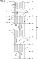
- FIG. 3 is an exploded planar view depicting an arrangement of the resonators 1, each of which comprises a resonance sound reducing body according to the first embodiment.
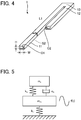
- FIG. 4 is a perspective view of a resonator 1.
- eight resonators 1 are disposed in the hollow body 40.
- Two resonators each of the eight resonators 1 provide a pair, and thus from the eight resonators 1 a total of four pairs is provided.
- Each of the four pairs of the eight resonators 1 is disposed at a different position in the circumferential direction DR of the first space S1.
- Two resonators 1 constituting a pair are disposed in differing directions from each other.
- an opening O1 each of the eight resonators 1 is displaced from another opening O1 by 45 degrees in the circumferential direction DR of the first space S1.
- an opening 02 each of the eight resonators 1 is displaced from another opening 02 by 45 degrees in the circumferential direction DR of the first space S1.
- FIG. 3 shows positions P1, P2, P3, P4, P5, P6, P7 and P8 at 45 degree intervals in the circumferential direction DR of the first space S1.
- the scale in the circumferential direction DR of the first space S1 is different from that in FIG. 1 .
- the number of the resonators 1 is not limited to eight, and may be one or more, and 7 or less, or 9 or more.
- the resonator 1 is a tube in which a second space S2 is formed.
- the resonator 1 can be readily manufactured using a suitable available tube.
- One end of the resonator 1 is provided with an opening O1, and the other end with an opening 02.
- the opening O1 and the opening 02 communicate with each other via the second space S2.
- the shape of the lateral cross section of the second space S2 is quadrangular. Accordingly, an advantage is obtained in that it is possible to make the lateral cross-sectional area of the second space S2 larger as compared with a case in which the shape of the lateral cross section of the second space S2 is round.
- the width W and height H of the second space S2 remain unchanged throughout the longitudinal direction of the second space S2.
- the second space S2 may have portions with a different width W and/or height H depending on a longitudinal position of the second space S2.
- the shape of the lateral cross section of the second space S2 is not limited to a quadrangle, and may be round, or a polygon other than a quadrangle, and so forth.
- the resonator 1 is shaped such that one end thereof is folded back toward the other end thereof. More specifically, the resonator 1 has two portions 11 and 12 that extend in parallel to each other and a portion 13 that connects the two portions.
- the portions 11 and 12 are disposed in a curve along the circumferential direction DR of the first space S1.
- the length L1 of the portion 11 is longer than the length L2 of the portion 12.
- the portion 13 extends in a direction perpendicular to the direction of extension of the portions 11 or 12 and connects an end each of the portion 11 and the portion 12.
- the length L3 of the portion 13 is shorter than the length L2 of the portion 12.
- the portions 11, 12, and 13 are formed integral.
- the portions 11, 12 and 13 may be made of a resin, an elastomer, a metal, or other appropriate materials, although not limited thereto.
- the portions 11, 12, and 13 may be formed separate from each other, in which case, each portion may be made of a different material.
- FIGS. 3 and 4 show a form in which the resonator 1 or the second space S2 has two bent portions, but the present disclosure is not limited thereto.
- the resonator 1 or the second space S2 may be shaped in such a way as to have one or more curved portions.
- the ratio of the length of the centerline LC2 of the second space S2 to that of the centerline LC1 of the first space S1 is 0.5 or within a range approximate thereto. Specifically, the range is from 0.45 to 0.55, inclusive, and preferably from 0.48 to 0.52, inclusive. With the ratio within the above range, it is possible to attain the effect of reducing an air column resonance in the first space S1. In the following, such an effect will be also referred to as "resonance reduction effect.”
- the centerline LC1 is a line drawn for a set of geometric centers of gravity in any and all cross sections of the first space S1.
- the cross section of the first space S1 is a cross section along a plane that includes an axial line AO, which is the center axis of the first space S1.
- the centerline LC2 is a line drawn for a set of geometric centers of gravity in any and all cross sections of the second space S2.
- the cross section of the second space S2 is a cross section perpendicular to the length direction of the second space S2.
- the two ends of the second space S2 of the resonator 1 comprise a pair of the openings O1 and 02, and accordingly, the resonator 1 functions as a double open-sided tube. Therefore, it is possible to reduce an air column resonance of a fundamental frequency and high-order frequencies generated in the first space S1.
- the fundamental frequency is a first order resonant frequency of the first space S1.
- the high-order frequencies are integer multiples of the first order resonant frequency of the first space S1. It is of note that a single open-sided tube resonator can also reduce an air column resonance of high-order frequencies, but such high-order frequencies are limited to odd multiples of a first-order resonance frequency.
- FIG. 3 shows a configuration in which the pair of the openings O1 and O2 are displaced from each other by 90 degrees in the circumferential direction DR of the first space S1. It suffices if the pair of the openings O1 and O2 are displaced from each other in the circumferential direction DR, and the present disclosure is not limited to the example shown in FIG. 3 .
- the pair of the openings O1 and O2 are preferably displaced at an angle within a range of from between 45 to 135 degrees (inclusive) in the circumferential direction DR, and more preferably, at an angle within a range of from between 80 to 100 degrees (inclusive), and even more preferably, at an angle within a range of from between 85 to 95 degrees (inclusive) in the circumferential direction DR.
- the pair of the openings O1 and O2 being displaced at an angle within any one of the above ranges, when an acoustic pressure of one of the pair of the openings O1 and O2 is high, an acoustic pressure of the other is low.
- the previously described resonance reduction effect is greater as compared with a case in which the pair of the openings O1 and O2 are arranged in a different manner.
- the first space S1 is annular in shape with the axial line AO as the center axis, in which case, the "angle in the circumferential direction DR" is equal to an angle defined by a line segment between the center of the opening O1 and the axial line AO, and a line segment between the center of the opening 02 and the axial line AO.
- the ratio of the distance L4 between the pair of the openings O1 and O2 to the length of the centerline LC2 of the second space S2 is within a range of from 0.45 to 0.55 (inclusive).
- the distance L4 is a distance between the center of the opening O1 and that of the opening 02 in a state in which no external force is applied to the resonator 1, namely, where the resonator 1 is not installed on the hollow body 40.
- the pair of the openings O1 and O2 can be displaced from each other at an angle within a range of from between 80 to 100 degrees (inclusive) in the circumferential direction DR when the length of the centerline LC2 in the second space S2 is configured to be within the previously described range.
- the openings O1 and O2 are arranged in lines along the circumferential direction DR.
- the length of the centerline LC2 in the second space S2 is generally equal to the sum total length of the above described lengths L1, L2 and L3. Further, in FIG.
- the portions 11 and 12 of the resonator 1 are arranged in parallel to the circumferential direction DR. However, if the pair of the openings O1 and O2 are displaced from each other at an angle within the above range, the portions 11 and 12 of the resonator 1 may be inclined with respect to the circumferential direction DR.
- the resonator 1 Since the resonant frequency of the first space S1 and the resonant frequency of the second space S2 have a predetermined relationship, the resonator 1 reduces an air column resonance of the first space S1 under the same principle as that of vibration damping by the dynamic vibration absorber. In the following, the action of the resonator 1 will be described.
- FIG. 5 is a diagram explaining the principle of vibration damping by a dynamic vibration absorber.
- a model that includes a main vibration system consisting of a spring k m and a mass m m and a sub vibration system attached to the main vibration system, wherein the sub vibration system consists of a spring k a , an attenuator c a , and a mass m a .
- the main vibration system is subject to the exciting force f (t)
- the sub vibration system functions as a dynamic vibration absorber that reduces vibration of the main vibration system.
- the function of the sub vibration system is realized when the natural angular frequency thereof matches or is close to the frequency of the exciting force f (t).
- the frequency of the exciting force f (t) corresponds to the resonant frequency of the first space S1 of the hollow body 40.
- the natural angular frequency of the sub vibration system corresponds to the resonant frequency of the second space S2 of the resonator 1.
- FIGS. 6 and 7 are each graphs showing relations between a frequency of resonant sound and a frequency response in the first space S1 for different positions of the resonators 1.
- the results shown in FIGS. 6 and 7 are obtained by applying an exciting force to the tire 30 at the position P1 and measuring an acoustic pressure produced in the tire 30 at the position P1.
- FIG. 6 is a graph showing relations between a frequency of resonant sound and a frequency response in the first space S1 for different positions of the resonators 1. The results shown in FIGS. 6 and 7 are obtained by applying an exciting force to the tire 30 at the position P1 and measuring an acoustic pressure produced in the tire 30 at the position P1.
- a case in which the resonator 1 is not provided is depicted by the dashed line; a case in which the positions of the pair of openings the O1 and O2 are respective positions P2 and P4 is depicted by the dot dashed line; and a case in which the positions of the pair of the openings O1 and O2 are respective positions P2 and P8 is depicted by the solid line.
- the dashed line a case in which the resonator 1 is not provided is depicted by the dashed line; a case in which the positions of the pair of openings the O1 and O2 are respective positions P2 and P4 is depicted by the dot dashed line; and a case in which the positions of the pair of the openings O1 and O2 are respective positions P2 and P8 is depicted by the solid line.
- FIG. 8 is a graph showing relations between a frequency of resonant sound and a frequency response in the first space for different numbers of the resonators 1. Similarly to the results shown in FIGS. 6 and 7 , the results shown in FIG. 8 are obtained by applying an exciting force to the tire 30 at the position P1 and measuring an acoustic pressure produced in the tire 30 at the position P1. In FIG.
- a case in which the resonator 1 is not provided is depicted by the dashed line; a case in which one resonator 1 is provided is depicted by the solid line; a case in which two resonators 1 are provided is depicted by the dot dashed line; and a case in which four resonators 1 are provided is depicted by the dot-dot dashed line.
- the pair of the openings O1 and O2 are located at the respective positions P2 and P8.
- the pair of the openings O1 and O2 of one of the two resonators 1 are located at the respective positions P2 and P8, and the pair of the openings O1 and O2 of the other resonator 1 are located at the respective positions P4 and P6.
- the pair of the openings O1 and O2 of one of the four resonators 1 are located at the respective positions P2 and P8; for another resonator 1 at the respective positions P4 and P6; for yet another resonator 1 at the respective positions P2 and P4; and for the other resonator 1 at the respective positions P6 and P8. It can be seen from the results shown in FIG. 8 that the greater the number of the resonators 1, the greater the resonance reduction effect.
- the resonance reduction effect can be increased in the hollow body 10 as a result of employing multiple resonators 1, as compared with a case of employing a single resonator 1. Further, since the multiple resonators 1 are disposed at a different position in the circumferential direction DR of the first space S1, variations in the resonance reduction effect can be reduced even if a direction of excitation exerted on the hollow body 40 changes. In particular, since the number of the resonators 1 is four or more, an advantage is obtained in that the variation in the resonance reduction effect can be easily reduced even if the direction of the excitation exerted on the hollow body 40 changes.
- FIG. 9 is a graph showing relations between a frequency of resonant sound and a frequency response in the first space for different thicknesses (cross-sectional areas) of the second space S2. Similarly to the results shown in FIGS. 6, 7 , and 8 , the results shown in FIG. 9 are obtained by applying an exciting force to the tire 30 at the position P1 and measuring an acoustic pressure produced in the tire 30 at the position P1. In FIG.
- a case in which the resonator 1 is not provided is depicted by the dashed line; a case in which the lateral cross-sectional area of the second space S2 is 470 mm 2 is depicted by the solid line; a case in which the lateral cross-sectional area of the second space S2 is 27 mm 2 is depicted by the dot dashed line, and a case in which the lateral cross-sectional area of the second space S2 is 170 mm 2 is depicted by the dot-dot dashed line.
- the pair of the openings O1 and O2 are located at the respective positions P2 and P8. From the results shown in FIG. 9 , it can be seen that the larger the lateral cross-sectional area of the second space S2 is, the greater the resonance reduction effect.
- the lateral cross-sectional area of the second space S2 is preferably within a range of from between 25 mm 2 to 1200 mm 2 .
- the lateral cross-sectional area being within this range, for example, when the hollow structure 10 is an assembly of an automotive vehicle tire 30 and a wheel 20, as in the present embodiment, or a structure having a first space S1 of the same size, it is easy to achieve both the effect of reducing an air column resonance in the first space S1 and the ready installation of the resonator 1 in the first space S1.
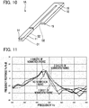
- FIG. 10 is a perspective view of a resonator 1A, which is a resonant sound reducing body according to the second embodiment.
- the resonator 1A is substantially the same as the resonator 1 of the first embodiment with the exception that the resonator 1A has a porous body 14 disposed in the opening O1 thereof, and a porous body 15 disposed in the opening 02 thereof.
- Each of the porous bodies 14 and 15 is air permeable.
- each of the porous bodies 14 and 15 is made of a nonwoven fabric.
- the porous bodies 14 and 15 can be easily manufactured by use of a suitable existing nonwoven fabric because each of the porous bodies 14 and 15 is made of a nonwoven fabric.
- FIG. 11 is a graph showing relations between a frequency of a resonant sound and a frequency response in the first space S1 for different thicknesses (different numbers of sheets) of the nonwoven fabric constituting each of the porous bodies 14 and 15.
- the results shown in FIG. 11 are obtained by applying an excitation force to the tire 30 at the position P1 and measuring a sound pressure produced by the tire 30 at the position P1, similarly to the results shown in FIG. 6 and 7 , and so forth.
- FIG. 11 is a graph showing relations between a frequency of a resonant sound and a frequency response in the first space S1 for different thicknesses (different numbers of sheets) of the nonwoven fabric constituting each of the porous bodies 14 and 15.
- Each of the porous bodies 14 and 15 need only be a porous body that is air permeable, and such a body is not limited to the nonwoven fabric, and may be, for example, a member having a plate-like portion in which a plurality of through-holes are formed.
- a member having a plate-like portion in which a plurality of through-holes are formed By employing such a member, an advantage is obtained in that an air permeability of the porous bodies 14 and 15 is unlikely to be adversely affected, even if dirt and the like adhere to the porous bodies 14 and 15 upon use.
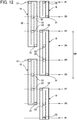
- FIG. 12 is an exploded view of the arrangement of the resonator 1B, which is a resonant sound reduction body according to the third embodiment.
- FIG. 13 is a cross-sectional view of the resonator 1B.
- FIG. 14 is a cross-sectional view taken along line B-B referenced in FIG. 13 .
- the outer shape of the resonator 1B is plate-shaped.
- Inside the resonator 1B there are formed a pair of second spaces S2 that are arranged in differing directions to each other.
- the pair of the openings O1 and O2 comprise the ends of each second space S2, and are open at one of the two surfaces of the resonator 1B.
- the resonator 1B has a lower plate 16, an upper plate 17, sidewalls 18, and partitions 19.
- the lower plate 16 and the upper plate 17 are arranged parallel to each other.
- Two pairs of the openings O1 and O2 are provided in the upper plate 17.
- the sidewalls 18 connect the outer periphery of the lower plate 16 and the upper plate 17 to each other over the entire circumference of the lower plate 16 and the upper plate 17.
- the partitions 19 divide a space surrounded by the lower plate 16, the upper plate 17, and the sidewalls 18 to form a pair of second spaces S2.
- the resonator 1B has an advantage over the resonator 1 or 1A of the above described embodiments in that it is easier to install the resonator 1B in the hollow body 40 as compared to the resonator 1 or 1A.
- FIG. 15 is a cross-sectional view of the hollow structure 10D according to Modification 1.
- the hollow structure 10D shown in FIG. 15 is substantially the same as the hollow structure 10 of the first embodiment, except that the resonator 1D is formed to be integral with the wheel 20D. That is, the hollow structure 10D has a wheel 20D, a tire 30 and a plurality of resonators 1D.
- the wheel 20D and the tire 30 comprise a hollow body 40D in which there is formed an annular first space S1.
- the plurality of resonators 1D are formed to be integral with the wheel 20D.
- a second space S2 is formed in each of the plurality of the resonators 1D, as in the above-described resonator 1.
- FIG. 1 is a cross-sectional view of the hollow structure 10D according to Modification 1.
- the hollow structure 10D shown in FIG. 15 is substantially the same as the hollow structure 10 of the first embodiment, except that the resonator 1D is formed to be integral with the
- the configuration 15 shows a configuration in which the plurality of the resonators 1D are disposed on the rim 21 of the wheel 20D. It is of note that the configuration is not limited to the above configuration so long as the pair of the openings O1 and O2 are located within the first space S1. For example, some or all of the plurality of the resonators 1D may be disposed in the disc 22.
- FIG. 16 is a cross-sectional view of a hollow structure 10E according to Modification 2.
- the hollow structure 10E shown in FIG. 16 is substantially the same as the hollow structure 10 of the first embodiment described above, with the exception that the resonator 1E is formed integral with the tire 30E. That is, the hollow structure 10E includes a wheel 20, a tire 30E, and a plurality of resonators 1E.
- the wheel 20 and the tire 30E comprise a hollow body 40E in which there is formed an annular first space S1.
- the plurality of the resonators 1E are formed integral with the tire 30E.
- a second space S2 is formed in each of the plurality of the resonators 1E.
- FIG. 1 is a cross-sectional view of a hollow structure 10E according to Modification 2.
- the hollow structure 10E shown in FIG. 16 is substantially the same as the hollow structure 10 of the first embodiment described above, with the exception that the resonator 1E is formed integral with the tire 30E. That is
- FIG 16 shows a configuration in which the plurality of the resonators 1E are disposed in the tread part 32 of the tire 30E.
- the configuration is not limited to the above configuration.
- some or all of the plurality of resonators 1E may be disposed in the sidewall part 33.
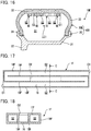
- FIG. 17 is a cross-sectional view of a resonator IF, which is a resonant sound reducing body according to Modification 3.
- FIG. 18 is a cross-sectional view taken along line C-C referenced in FIG. 17 .
- the resonator IF shown in FIGS. 17 and 18 is substantially the same as the resonator 1B of the third embodiment, with the exception that the orientation of the opening O1 and the size of the opening 02 differ.
- the outer shape of the resonator IF is plate-shaped. Inside the resonator IF there are formed a pair of second spaces S2 arranged in differing directions. In the present modification, each opening O1 opens sideways on a side of the resonator IF.
- the opening 02 is shared by the pair of the second spaces S2 and opens at one of the two surfaces of the resonator IF.
- the resonator IF has a lower plate 16, an upper plate 17F, sidewalls 18F, and partitions 19F.
- the lower plate 16 and the upper plate 17F are arranged parallel to each other.
- the upper plate 17F is provided with one opening 02 that is shared by the pair of the second spaces S2.
- the sidewalls 18F are substantially the same as the sidewalls 18 of the third embodiment, with the exception that one pair of the openings O1 is provided.
- the partitions 19F are substantially the same as the partitions 19 of the third embodiment, with the exception that two partitions separating the pair of the second spaces S2 are excluded. According to the resonator IF, the same effects as those attained by the resonator 1B of the third embodiment can be attained. Furthermore, an advantage is obtained in that exclusion of the two partitions facilitates ease of manufacture of the resonator IF.
- the hollow body is described as a structure consisting of a wheel and a tire, but the hollow body is not limited thereto.
- the resonant sound reducing body can be used in various types of hollow bodies with annular spaces in which an air column resonance is to be reduced.
- the first space rather than being formed as a ring, may be annular portions.
- a hollow structure according to a preferred aspect (first aspect) of the present disclosure has a hollow body with an annular first space; and at least one resonator in which there is formed an elongated second space, with a pair of openings at two ends thereof, each of the pair of openings comprising an opening that opens inwardly toward an interior of the first space.
- a ratio of a length of a centerline of the second space to a length of a centerline of the first space is within a range of from 0.45 to 0.55, and the second space has a bent or curved portion.
- an air column resonance of a fundamental frequency and high-order frequencies generated in the first space since at least one resonator is used in which there is formed an elongated second space with a pair of openings at two ends thereof, with the openings being located within the first space.
- the effect of reducing an air column resonance can be achieved with the ratio of the length of the centerline of the second space to the length of the centerline of the first space being within a range of from 0.45 to 0.55.
- the at least one resonator comprises a plurality of resonators, in each of which there is formed the second space. According to the above aspect, the effect of reducing an air column resonance of the first space can be increased as compared to the case of a single resonator.
- the plurality of resonators are disposed at different positions in a circumferential direction of the first space. According to the above aspect, even if the direction of the excitation relative to the hollow body changes, a variation in air column resonance reduction effect in the first space can be easily reduced.
- the plurality of resonators comprise four or more resonators. According to the above aspect, even if the direction of excitation relative to the hollow body changes, the variation in air column resonance reduction effect in the first space can be easily reduced.
- the hollow structure further includes an air-permeable porous body, which is disposed at the each of the pair of the openings. According to this aspect, it is possible to adjust the air column resonance reduction effect in the first space. By appropriately setting the air permeability of the porous body, the reduction effect of an air column resonance can be enhanced as compared with a case in which no porous body is used.
- the porous body comprises a nonwoven fabric. According to this aspect, it is possible to readily manufacture the porous body by use of a suitable available nonwoven fabric.
- the porous body comprises a member that has a plate-shaped portion in which there is formed a plurality of through-holes. According to the above aspect, even if dirt and the like adhere to the porous body with use, an advantage is obtained in that the air permeability of the porous body is hardly reduced.
- a lateral cross-sectional area of the second part is within a range of from 25 mm 2 to 1200 mm 2 .
- a shape of a lateral cross section of the second part is a quadrangle. According to the above aspect, an advantage is obtained in which the lateral cross-sectional area of the second space can be easily increased.
- each of the at least one resonator is tube-shaped. According to the above aspect, the resonator can be easily manufactured using a suitable existing tube body.
- an outer shape of each of the at least one resonator is plate-shaped. According to the above aspect, when the resonator is separately formed from the hollow body, an advantage is obtained in that the resonator can be easily installed in the hollow body.
- the pair of openings are displaced from each other at an angle in a range of from 80 to 100 degrees along a circumferential direction of the first space. According to the above aspect, the effect is enhanced as compared with a case in which the pair of openings are arranged in any other arrangement.
- a resonant sound reducing body is a resonant sound reducing body in which there is formed an elongated second space with a pair of openings at two ends thereof, the resonant sound reducing body being disposed in a hollow body in which there is formed an annular first space, with the second space having a bent or curved portion, and a ratio of a distance between the pair of openings to a length of a centerline of the second space being within a range of from 0.45 to 0.55.
- the effect of reducing an air column resonance in the first space can be achieved when the ratio of the length of the centerline of the second space to the length of the centerline of the first space is within a range of from 0.45 to 0.55. Since the ratio of the distance between the pair of the openings to the length of the centerline of the second space is within a range of from 0.45 to 0.55, the pair of the openings can be displaced from each other at an angle within a range of from 80 to 100 degrees (inclusive) in the circumferential direction of the first space by configuring the ratio of the length of the centerline of the second space to the length of the centerline of the first space to be within the above range.
Landscapes
- Engineering & Computer Science (AREA)
- Physics & Mathematics (AREA)
- Acoustics & Sound (AREA)
- Multimedia (AREA)
- Mechanical Engineering (AREA)
- Soundproofing, Sound Blocking, And Sound Damping (AREA)
- Tires In General (AREA)
Abstract
Description
- The present disclosure relates to a hollow structure and a resonant sound reducing body.
- A hollow body in which there is formed an annular space is constituted of a tire and a rim assembly. An air column resonance generated inside an air chamber of the tire causes noise such as road noise in automobiles. To suppress such noise,
Patent Document 1, for example, discloses disposing inside a tire air chamber a sub-chamber comprising Helmholtz resonators. -
Patent Document 1 Japanese Patent Application Laid-Open Publication No.2008-030505 - The technique disclosed in
Patent Document 1 is subject to the following drawbacks "a" and "b" caused by use of Helmholtz resonators: - Drawback a: Helmholtz resonators have only a single resonant frequency. Consequently, an air column resonance can be reduced for only a fundamental frequency or for only one of its high-order frequencies, which results in an insufficient overall reduction in air column resonance; and
- Drawback b: the sub-chamber member is subject to deformation by centrifugal forces generated by tire rotation, etc., which may cause a change in resonant frequency of the Helmholtz resonator, and consequently a failure to achieve a reduction in air column resonance.
- In view of the foregoing problems, an object of the present disclosure is to sufficiently reduce an air column resonance inside a hollow body in which there is formed an annular space.
- To solve the above-stated problems, a hollow structure according to a preferred aspect of the present disclosure has a hollow body with an annular first space; and at least one resonator in which there is formed an elongated second space with a pair of openings at two ends thereof, each of the pair of openings comprising an opening that opens inwardly toward an interior of the first space, a ratio of a length of a centerline of the second space to a length of a centerline of the first space being within a range of from 0.45 to 0.55, and the second space having a bent or curved portion.
- A resonant sound reducing body according to a preferred aspect of the present disclosure is a resonant sound reducing body in which there is formed an elongated second space with a pair of openings at two ends thereof, the resonant sound reducing body being disposed in a hollow body in which there is formed an annular first space, with the second space having a bent or curved portion, and a ratio of a distance between the pair of openings to a length of a centerline of the second space being within a range of from 0.45 to 0.55.
-
-
FIG. 1 is a side view of a hollow structure according to a first embodiment. -
FIG. 2 is a cross-sectional view taken along line A-A referenced inFIG. 1 . -
FIG. 3 is an exploded planar view depicting an arrangement of a resonant sound reducing body according to the first embodiment. -
FIG. 4 is a perspective view of the resonant sound reducing body according to the first embodiment. -
FIG. 5 is a diagram explaining the principle of vibration damping by a dynamic vibration absorber. -
FIG. 6 is a graph showing relations between a frequency of resonant sound and a frequency response in the first space for different positions of the resonators. -
FIG. 7 is a graph showing relations between a frequency of resonant sound and a frequency response in the first space for different positions of the resonators. -
FIG. 8 is a graph showing relations between a frequency of resonant sound and a frequency response in the first space for different numbers of the resonators. -
FIG. 9 is a graph showing relations between a frequency of resonant sound and a frequency response in the first space for different diameters (cross-sectional areas) of a second space. -
FIG. 10 is a perspective view of a resonant sound reducing body according to a second embodiment. -
FIG. 11 is a graph showing relations between a frequency of resonant sound and a frequency response in the first space for different thicknesses (number of sheets) of a nonwoven fabric. -
FIG. 12 is an exploded view showing an arrangement of a resonant sound reducing body according to a third embodiment. -
FIG. 13 is a cross-sectional view of a resonant sound reducing body according to a third embodiment. -
FIG. 14 is a cross-sectional view taken along line B-B referenced inFIG. 13 . -
FIG. 15 is a cross-sectional view of a hollow structure according toModification 1. -
FIG. 16 is a cross-sectional view of a hollow structure according toModification 2. -
FIG. 17 is a cross-sectional view of a resonant sound reducing body according to Modification 3. -
FIG. 18 is a cross-sectional view taken along Line C-C referenced inFIG. 17 . - A first embodiment of the present disclosure will now be described with reference to the drawings. It is of note that a size and scale of each element in the drawings may not be the same as those of actual elements. Further, in the following embodiments preferred specific examples of the present disclosure are described, and these examples include preferable technical limitations. Notwithstanding, the scope of the present disclosure is not limited to the examples described unless specific statement to the contrary is made.
-
FIG. 1 is a side view of ahollow structure 10 according to the first embodiment.FIG. 2 is a cross-sectional view taken along line A-A referenced inFIG. 1 . Thehollow structure 10 depicted inFIGS. 1 and 2 is a vehicle wheel structure for automobiles. As shown inFIGS. 1 and 2 , thehollow structure 10 includes awheel 20, atire 30, and a plurality ofresonators 1. Thewheel 20 and thetire 30 constitute ahollow body 40 in which there is formed an annular first space S1. Theresonators 1 each comprises a resonant sound reducing body to reduce an air column resonance of the first space S1. Theresonators 1 each has an elongated second space S2 with a pair of openings O1 and O2 at two ends thereof, each of the pair of the openings comprising an opening that opens inwardly toward the interior of the first space S1, as will be described in detail later. In the following, each part of thehollow structure 10 will be described in turn. - The
wheel 20 is for use in a vehicle such as an automobile. Thewheel 20 according to the present embodiment may be structured in the same way as a known vehicle wheel. As shown inFIG. 2 , thewheel 20 has arim 21 and adisk 22. Therim 21 is an annular wheel rim. There are provided on the outer circumferential surface of therim 21 a wheel wellpart 21a and a pair ofbead seat parts 21b along a circumferential direction of therim 21. The wheel wellpart 21a is concave and extends in the circumferential direction of therim 21. The pair ofbead seat parts 21b is used for fixedly fitting thetire 30. There are also provided at each side of therim 21 in a widthwise direction a pair ofrim flanges parts 21c, with each of therim flange parts 21c sandwiching a correspondingbead seat part 21b. The pair of therim flange parts 21c protrudes outward in the radial direction of therim 21. Thedisk 22 is attached to therim 21 at an inner side thereof and has a portion mounted to an axle hub (not shown) of the vehicle.FIG. 2 illustratively depicts a case in which thedisk 22 is formed integral with therim 21. It is of note that thedisk 22 may be formed separate from therim 21, in which case therim 21 and thedisk 22 are attached to each other by use of bolts or the like. - The
rim 21 and thedisk 22 may be made of an aluminum alloy, a magnesium alloy, an iron, and so forth. In a case that thedisk 22 is formed separate from therim 21, therim 21 and thedisk 22 may be made of different materials. It is of note that althoughFIG. 2 illustrates a configuration in which therim 21 is constituted of a single member, therim 21 may be constituted of multiple members. In this case, the multiple members that constitute therim 21 may be made of different materials. - The
tire 30 is assembled together with awheel 20, and an annular first space S1 is formed between thetire 30 and thewheel 20. Thetire 30 according to the present embodiment is structured in the same way as a known tire used, for example, in an automobile. As shown inFIG. 2 , thetire 30 has a pair ofbead parts 31, atread part 32, and a pair ofsidewall parts 33. The pair ofbead parts 31 fits with the pair ofbead seat parts 21b. Thetread part 32 comes into contact with a road surface. The pair ofsidewall parts 33 connects the pair ofbead parts 31 and thetread part 32. Thetire 30 is mainly made from rubber materials. Although not shown, thetire 30 also has known portions such a bead, belt, and carcass made from metallic materials or fiber materials in addition to portions made from the rubber materials. - As shown in
FIG. 2 , a plurality ofresonators 1 is disposed inside the first space S1. By this configuration, each of the pair of openings O1 and O2 comprises an opening that opens inwardly toward the interior of the first space S1, the pair of the openings O1 and O2 corresponding to the two ends of the second space S2 each of theresonators 1. Theresonators 1 according to the present embodiment are positioned on the outer circumferential surface of therim 21. Although not shown in the figures, theresonators 1 are attached to therim 21 by use of an adhesive, screws, a binder, or the like. -
FIG. 3 is an exploded planar view depicting an arrangement of theresonators 1, each of which comprises a resonance sound reducing body according to the first embodiment.FIG. 4 is a perspective view of aresonator 1. As shown inFIG. 3 , according to the present embodiment eightresonators 1 are disposed in thehollow body 40. Two resonators each of the eightresonators 1 provide a pair, and thus from the eight resonators 1 a total of four pairs is provided. Each of the four pairs of the eightresonators 1 is disposed at a different position in the circumferential direction DR of the first space S1. Tworesonators 1 constituting a pair are disposed in differing directions from each other. In the present embodiment, an opening O1 each of the eightresonators 1 is displaced from another opening O1 by 45 degrees in the circumferential direction DR of the first space S1. Likewise, anopening 02 each of the eightresonators 1 is displaced from anotheropening 02 by 45 degrees in the circumferential direction DR of the first space S1.FIG. 3 shows positions P1, P2, P3, P4, P5, P6, P7 and P8 at 45 degree intervals in the circumferential direction DR of the first space S1. For convenience of explanation, inFIG. 3 the scale in the circumferential direction DR of the first space S1 is different from that inFIG. 1 . It is of note that the number of theresonators 1 is not limited to eight, and may be one or more, and 7 or less, or 9 or more. - As shown in
FIG. 4 , theresonator 1 is a tube in which a second space S2 is formed. Theresonator 1 can be readily manufactured using a suitable available tube. One end of theresonator 1 is provided with an opening O1, and the other end with anopening 02. The opening O1 and theopening 02 communicate with each other via the second space S2. In the present embodiment, the shape of the lateral cross section of the second space S2 is quadrangular. Accordingly, an advantage is obtained in that it is possible to make the lateral cross-sectional area of the second space S2 larger as compared with a case in which the shape of the lateral cross section of the second space S2 is round. The width W and height H of the second space S2 remain unchanged throughout the longitudinal direction of the second space S2. It is of note that the second space S2 may have portions with a different width W and/or height H depending on a longitudinal position of the second space S2. The shape of the lateral cross section of the second space S2 is not limited to a quadrangle, and may be round, or a polygon other than a quadrangle, and so forth. - The
resonator 1 according to the present embodiment is shaped such that one end thereof is folded back toward the other end thereof. More specifically, theresonator 1 has twoportions portion 13 that connects the two portions. Theportions portion 11 is longer than the length L2 of theportion 12. Theportion 13 extends in a direction perpendicular to the direction of extension of theportions portion 11 and theportion 12. The length L3 of theportion 13 is shorter than the length L2 of theportion 12. InFIGS. 3 and4 , theportions portions portions FIGS. 3 and4 show a form in which theresonator 1 or the second space S2 has two bent portions, but the present disclosure is not limited thereto. Theresonator 1 or the second space S2 may be shaped in such a way as to have one or more curved portions. - The ratio of the length of the centerline LC2 of the second space S2 to that of the centerline LC1 of the first space S1 is 0.5 or within a range approximate thereto. Specifically, the range is from 0.45 to 0.55, inclusive, and preferably from 0.48 to 0.52, inclusive. With the ratio within the above range, it is possible to attain the effect of reducing an air column resonance in the first space S1. In the following, such an effect will be also referred to as "resonance reduction effect."
- The centerline LC1 is a line drawn for a set of geometric centers of gravity in any and all cross sections of the first space S1. The cross section of the first space S1 is a cross section along a plane that includes an axial line AO, which is the center axis of the first space S1. The centerline LC2 is a line drawn for a set of geometric centers of gravity in any and all cross sections of the second space S2. The cross section of the second space S2 is a cross section perpendicular to the length direction of the second space S2.
- The two ends of the second space S2 of the
resonator 1 comprise a pair of the openings O1 and 02, and accordingly, theresonator 1 functions as a double open-sided tube. Therefore, it is possible to reduce an air column resonance of a fundamental frequency and high-order frequencies generated in the first space S1. The fundamental frequency is a first order resonant frequency of the first space S1. The high-order frequencies are integer multiples of the first order resonant frequency of the first space S1. It is of note that a single open-sided tube resonator can also reduce an air column resonance of high-order frequencies, but such high-order frequencies are limited to odd multiples of a first-order resonance frequency. - The pair of the openings O1 and O2 are displaced from each other in the circumferential direction DR of the first space S1. By this arrangement, the resonance reduction effect is enhanced.
FIG. 3 shows a configuration in which the pair of the openings O1 and O2 are displaced from each other by 90 degrees in the circumferential direction DR of the first space S1. It suffices if the pair of the openings O1 and O2 are displaced from each other in the circumferential direction DR, and the present disclosure is not limited to the example shown inFIG. 3 . The pair of the openings O1 and O2 are preferably displaced at an angle within a range of from between 45 to 135 degrees (inclusive) in the circumferential direction DR, and more preferably, at an angle within a range of from between 80 to 100 degrees (inclusive), and even more preferably, at an angle within a range of from between 85 to 95 degrees (inclusive) in the circumferential direction DR. As a result of the pair of the openings O1 and O2 being displaced at an angle within any one of the above ranges, when an acoustic pressure of one of the pair of the openings O1 and O2 is high, an acoustic pressure of the other is low. Therefore, the previously described resonance reduction effect is greater as compared with a case in which the pair of the openings O1 and O2 are arranged in a different manner. It is of note that in the present embodiment the first space S1 is annular in shape with the axial line AO as the center axis, in which case, the "angle in the circumferential direction DR" is equal to an angle defined by a line segment between the center of the opening O1 and the axial line AO, and a line segment between the center of theopening 02 and the axial line AO. - Further, the ratio of the distance L4 between the pair of the openings O1 and O2 to the length of the centerline LC2 of the second space S2 is within a range of from 0.45 to 0.55 (inclusive). The distance L4 is a distance between the center of the opening O1 and that of the
opening 02 in a state in which no external force is applied to theresonator 1, namely, where theresonator 1 is not installed on thehollow body 40. By configuring the ratio of the distance L4 to the length of the centerline LC2 to fall within the range of from 0.45 to 0.55, the pair of the openings O1 and O2 can be displaced from each other at an angle within a range of from between 80 to 100 degrees (inclusive) in the circumferential direction DR when the length of the centerline LC2 in the second space S2 is configured to be within the previously described range. The openings O1 and O2 are arranged in lines along the circumferential direction DR. The length of the centerline LC2 in the second space S2 is generally equal to the sum total length of the above described lengths L1, L2 and L3. Further, inFIG. 3 , theportions resonator 1 are arranged in parallel to the circumferential direction DR. However, if the pair of the openings O1 and O2 are displaced from each other at an angle within the above range, theportions resonator 1 may be inclined with respect to the circumferential direction DR. - Since the resonant frequency of the first space S1 and the resonant frequency of the second space S2 have a predetermined relationship, the
resonator 1 reduces an air column resonance of the first space S1 under the same principle as that of vibration damping by the dynamic vibration absorber. In the following, the action of theresonator 1 will be described. -
FIG. 5 is a diagram explaining the principle of vibration damping by a dynamic vibration absorber. There is shown inFIG. 5 a model that includes a main vibration system consisting of a spring km and a mass mm and a sub vibration system attached to the main vibration system, wherein the sub vibration system consists of a spring ka, an attenuator ca, and a mass ma. In this model, the main vibration system is subject to the exciting force f (t), and the sub vibration system functions as a dynamic vibration absorber that reduces vibration of the main vibration system. The function of the sub vibration system is realized when the natural angular frequency thereof matches or is close to the frequency of the exciting force f (t). - The frequency of the exciting force f (t) corresponds to the resonant frequency of the first space S1 of the
hollow body 40. Further, the natural angular frequency of the sub vibration system corresponds to the resonant frequency of the second space S2 of theresonator 1. By configuring the ratio of the length of the centerline LC2 in the second space S2 to the length of the centerline LC1 in the first space S1 to be approximately 0.5, the resonant frequency of the second space S2 matches or approaches the resonant frequency of the first space S1. As a result, the resonance reduction effect is achieved. The resonant frequency of the second space S2 in theresonator 1 is dependent on the length of the centerline LC2 in the second space S2. The resonant frequency of theresonator 1 is thus unlikely to vary even if theresonator 1 is deformed under centrifugal force, or the like, and thus the resonance reduction effect can be advantageously maintained. -
FIGS. 6 and 7 are each graphs showing relations between a frequency of resonant sound and a frequency response in the first space S1 for different positions of theresonators 1. The results shown inFIGS. 6 and 7 are obtained by applying an exciting force to thetire 30 at the position P1 and measuring an acoustic pressure produced in thetire 30 at the position P1. InFIG. 6 , a case in which theresonator 1 is not provided is depicted by the dashed line; a case in which the positions of the pair of openings the O1 and O2 are respective positions P2 and P4 is depicted by the dot dashed line; and a case in which the positions of the pair of the openings O1 and O2 are respective positions P2 and P8 is depicted by the solid line. InFIG. 7 , a case in which theresonator 1 is not provided is depicted by the dashed line; a case in which the positions of the pair of the openings O1 and O2 are respective positions P4 and P6 is depicted by the dot dashed line; and a case in which the positions of the pair of the openings O1 and O2 are respective positions P2 and P8 is depicted by the solid line. From the results shown inFIGS. 6 and 7 , it can be seen that the resonance reduction effect is highest when theresonator 1 is disposed either closest to or farthest away from the excitation position P1, which is the position at which excitation is applied. It can also be seen that the resonance reduction effect varies depending on a relationship between the excitation position and a position of theresonator 1. It is of note that the lower the peak of the frequency response, the higher the resonance reduction effect. -
FIG. 8 is a graph showing relations between a frequency of resonant sound and a frequency response in the first space for different numbers of theresonators 1. Similarly to the results shown inFIGS. 6 and 7 , the results shown inFIG. 8 are obtained by applying an exciting force to thetire 30 at the position P1 and measuring an acoustic pressure produced in thetire 30 at the position P1. InFIG. 8 , a case in which theresonator 1 is not provided is depicted by the dashed line; a case in which oneresonator 1 is provided is depicted by the solid line; a case in which tworesonators 1 are provided is depicted by the dot dashed line; and a case in which fourresonators 1 are provided is depicted by the dot-dot dashed line. In the case depicted by the solid line inFIG. 8 , the pair of the openings O1 and O2 are located at the respective positions P2 and P8. In the case depicted by the dot dashed line inFIG. 8 , the pair of the openings O1 and O2 of one of the tworesonators 1 are located at the respective positions P2 and P8, and the pair of the openings O1 and O2 of theother resonator 1 are located at the respective positions P4 and P6. In the case depicted by the dot-dot dashed line inFIG. 8 , the pair of the openings O1 and O2 of one of the fourresonators 1 are located at the respective positions P2 and P8; for anotherresonator 1 at the respective positions P4 and P6; for yet anotherresonator 1 at the respective positions P2 and P4; and for theother resonator 1 at the respective positions P6 and P8. It can be seen from the results shown inFIG. 8 that the greater the number of theresonators 1, the greater the resonance reduction effect. - As will be apparent from the results shown in
FIG. 8 , the resonance reduction effect can be increased in thehollow body 10 as a result of employingmultiple resonators 1, as compared with a case of employing asingle resonator 1. Further, since themultiple resonators 1 are disposed at a different position in the circumferential direction DR of the first space S1, variations in the resonance reduction effect can be reduced even if a direction of excitation exerted on thehollow body 40 changes. In particular, since the number of theresonators 1 is four or more, an advantage is obtained in that the variation in the resonance reduction effect can be easily reduced even if the direction of the excitation exerted on thehollow body 40 changes. -
FIG. 9 is a graph showing relations between a frequency of resonant sound and a frequency response in the first space for different thicknesses (cross-sectional areas) of the second space S2. Similarly to the results shown inFIGS. 6, 7 , and8 , the results shown inFIG. 9 are obtained by applying an exciting force to thetire 30 at the position P1 and measuring an acoustic pressure produced in thetire 30 at the position P1. InFIG. 9 , a case in which theresonator 1 is not provided is depicted by the dashed line; a case in which the lateral cross-sectional area of the second space S2 is 470 mm2 is depicted by the solid line; a case in which the lateral cross-sectional area of the second space S2 is 27 mm2 is depicted by the dot dashed line, and a case in which the lateral cross-sectional area of the second space S2 is 170 mm2 is depicted by the dot-dot dashed line. In all cases, the pair of the openings O1 and O2 are located at the respective positions P2 and P8. From the results shown inFIG. 9 , it can be seen that the larger the lateral cross-sectional area of the second space S2 is, the greater the resonance reduction effect. - Upon further analysis separate from the results shown in
FIG. 9 , the lateral cross-sectional area of the second space S2 is preferably within a range of from between 25 mm2 to 1200 mm2. With the lateral cross-sectional area being within this range, for example, when thehollow structure 10 is an assembly of anautomotive vehicle tire 30 and awheel 20, as in the present embodiment, or a structure having a first space S1 of the same size, it is easy to achieve both the effect of reducing an air column resonance in the first space S1 and the ready installation of theresonator 1 in the first space S1. - A second embodiment of the present disclosure will now be described. For elements having actions or functions identical to those of the first embodiment in the embodiment illustrated in the following, the same reference signs as those in the descriptions of the first embodiment are used and detailed explanation of such elements is omitted, as appropriate.
-
FIG. 10 is a perspective view of a resonator 1A, which is a resonant sound reducing body according to the second embodiment. As shown inFIG. 10 , the resonator 1A is substantially the same as theresonator 1 of the first embodiment with the exception that the resonator 1A has aporous body 14 disposed in the opening O1 thereof, and aporous body 15 disposed in theopening 02 thereof. Each of theporous bodies porous bodies FIG. 10 illustrates a case in which each of theporous bodies porous bodies porous bodies -
FIG. 11 is a graph showing relations between a frequency of a resonant sound and a frequency response in the first space S1 for different thicknesses (different numbers of sheets) of the nonwoven fabric constituting each of theporous bodies FIG. 11 are obtained by applying an excitation force to thetire 30 at the position P1 and measuring a sound pressure produced by thetire 30 at the position P1, similarly to the results shown inFIG. 6 and 7 , and so forth. InFIG. 11 , a case in which no nonwoven fabric is provided is depicted by the solid line; a case in which one sheet of nonwoven fabric is provided is depicted by the dot dashed line; a case in which two sheets of the nonwoven fabric are provided is depicted by the dot-dot dashed line; and a case in which four sheets of the nonwoven fabric are provided is depicted by the dashed line. In all cases, the pair of the openings O1 and O2 are located at the respective positions P2 and P8. From the results shown inFigure 11 , it can be seen that use of the nonwoven fabric with an appropriate thickness increases the resonance reduction effect. In other words, by setting to an adequate degree air permeability of theporous bodies porous bodies - Each of the
porous bodies porous bodies porous bodies - A third embodiment of the present disclosure will now be described. For elements having actions or functions identical to those of the first embodiment in the embodiment illustrated in the following, the same reference signs as those in the descriptions of the first embodiment are used and detailed explanation of such elements is omitted, as appropriate.
-
FIG. 12 is an exploded view of the arrangement of theresonator 1B, which is a resonant sound reduction body according to the third embodiment.FIG. 13 is a cross-sectional view of theresonator 1B.FIG. 14 is a cross-sectional view taken along line B-B referenced inFIG. 13 . As shown inFIG. 12 , the outer shape of theresonator 1B is plate-shaped. Inside theresonator 1B there are formed a pair of second spaces S2 that are arranged in differing directions to each other. In the present embodiment, the pair of the openings O1 and O2 comprise the ends of each second space S2, and are open at one of the two surfaces of theresonator 1B. As shown inFIGS. 13 and 14 , theresonator 1B has alower plate 16, anupper plate 17, sidewalls 18, andpartitions 19. Thelower plate 16 and theupper plate 17 are arranged parallel to each other. Two pairs of the openings O1 and O2 are provided in theupper plate 17. Thesidewalls 18 connect the outer periphery of thelower plate 16 and theupper plate 17 to each other over the entire circumference of thelower plate 16 and theupper plate 17. Thepartitions 19 divide a space surrounded by thelower plate 16, theupper plate 17, and thesidewalls 18 to form a pair of second spaces S2. Theresonator 1B has an advantage over theresonator 1 or 1A of the above described embodiments in that it is easier to install theresonator 1B in thehollow body 40 as compared to theresonator 1 or 1A. - The present disclosure is not limited to the above embodiments, and may be modified in a variety of ways as described below. Two or more modes of the above embodiments and the modifications may be combined, as appropriate.
-
FIG. 15 is a cross-sectional view of thehollow structure 10D according toModification 1. Thehollow structure 10D shown inFIG. 15 is substantially the same as thehollow structure 10 of the first embodiment, except that theresonator 1D is formed to be integral with thewheel 20D. That is, thehollow structure 10D has awheel 20D, atire 30 and a plurality ofresonators 1D. Thewheel 20D and thetire 30 comprise ahollow body 40D in which there is formed an annular first space S1. The plurality ofresonators 1D are formed to be integral with thewheel 20D. A second space S2 is formed in each of the plurality of theresonators 1D, as in the above-describedresonator 1.FIG. 15 shows a configuration in which the plurality of theresonators 1D are disposed on therim 21 of thewheel 20D. It is of note that the configuration is not limited to the above configuration so long as the pair of the openings O1 and O2 are located within the first space S1. For example, some or all of the plurality of theresonators 1D may be disposed in thedisc 22. -
FIG. 16 is a cross-sectional view of ahollow structure 10E according toModification 2. Thehollow structure 10E shown inFIG. 16 is substantially the same as thehollow structure 10 of the first embodiment described above, with the exception that theresonator 1E is formed integral with thetire 30E. That is, thehollow structure 10E includes awheel 20, atire 30E, and a plurality ofresonators 1E. Thewheel 20 and thetire 30E comprise ahollow body 40E in which there is formed an annular first space S1. The plurality of theresonators 1E are formed integral with thetire 30E. As in the above-describedresonator 1, a second space S2 is formed in each of the plurality of theresonators 1E.FIG. 16 shows a configuration in which the plurality of theresonators 1E are disposed in thetread part 32 of thetire 30E. The configuration is not limited to the above configuration. For example, some or all of the plurality ofresonators 1E may be disposed in thesidewall part 33. -
FIG. 17 is a cross-sectional view of a resonator IF, which is a resonant sound reducing body according to Modification 3.FIG. 18 is a cross-sectional view taken along line C-C referenced inFIG. 17 . The resonator IF shown inFIGS. 17 and 18 is substantially the same as theresonator 1B of the third embodiment, with the exception that the orientation of the opening O1 and the size of theopening 02 differ. Specifically, the outer shape of the resonator IF is plate-shaped. Inside the resonator IF there are formed a pair of second spaces S2 arranged in differing directions. In the present modification, each opening O1 opens sideways on a side of the resonator IF. Theopening 02 is shared by the pair of the second spaces S2 and opens at one of the two surfaces of the resonator IF. As shown inFIG. 17 and 18 , the resonator IF has alower plate 16, anupper plate 17F, sidewalls 18F, andpartitions 19F. Thelower plate 16 and theupper plate 17F are arranged parallel to each other. Theupper plate 17F is provided with oneopening 02 that is shared by the pair of the second spaces S2. Thesidewalls 18F are substantially the same as thesidewalls 18 of the third embodiment, with the exception that one pair of the openings O1 is provided. Thepartitions 19F are substantially the same as thepartitions 19 of the third embodiment, with the exception that two partitions separating the pair of the second spaces S2 are excluded. According to the resonator IF, the same effects as those attained by theresonator 1B of the third embodiment can be attained. Furthermore, an advantage is obtained in that exclusion of the two partitions facilitates ease of manufacture of the resonator IF. - In the above embodiments or modifications, the hollow body is described as a structure consisting of a wheel and a tire, but the hollow body is not limited thereto. The resonant sound reducing body can be used in various types of hollow bodies with annular spaces in which an air column resonance is to be reduced. Further, the first space, rather than being formed as a ring, may be annular portions.
- The following aspects are derivable from the above described embodiments and modifications.
- A hollow structure according to a preferred aspect (first aspect) of the present disclosure has a hollow body with an annular first space; and at least one resonator in which there is formed an elongated second space, with a pair of openings at two ends thereof, each of the pair of openings comprising an opening that opens inwardly toward an interior of the first space. A ratio of a length of a centerline of the second space to a length of a centerline of the first space is within a range of from 0.45 to 0.55, and the second space has a bent or curved portion. According to the above aspect, it is possible to reduce an air column resonance of a fundamental frequency and high-order frequencies generated in the first space since at least one resonator is used in which there is formed an elongated second space with a pair of openings at two ends thereof, with the openings being located within the first space. The effect of reducing an air column resonance can be achieved with the ratio of the length of the centerline of the second space to the length of the centerline of the first space being within a range of from 0.45 to 0.55. An advantage is obtained in that since the resonant frequency of the second space in the resonator is determined by the length of the centerline in the second space, the resonant frequency of the resonator is unlikely to change even if the resonator is deformed by centrifugal forces or the like, and thus the above described effect can be maintained.
- In a preferred example (second aspect) of the first aspect, the at least one resonator comprises a plurality of resonators, in each of which there is formed the second space. According to the above aspect, the effect of reducing an air column resonance of the first space can be increased as compared to the case of a single resonator.
- In a preferred example (third aspect) of the second aspect, the plurality of resonators are disposed at different positions in a circumferential direction of the first space. According to the above aspect, even if the direction of the excitation relative to the hollow body changes, a variation in air column resonance reduction effect in the first space can be easily reduced.
- In a preferred example (fourth aspect) of the second or the third aspect, the plurality of resonators comprise four or more resonators. According to the above aspect, even if the direction of excitation relative to the hollow body changes, the variation in air column resonance reduction effect in the first space can be easily reduced.
- In a preferred example (fifth aspect) of any one of the first to fourth aspects, the hollow structure further includes an air-permeable porous body, which is disposed at the each of the pair of the openings. According to this aspect, it is possible to adjust the air column resonance reduction effect in the first space. By appropriately setting the air permeability of the porous body, the reduction effect of an air column resonance can be enhanced as compared with a case in which no porous body is used.
- In a preferred example (sixth aspect) of the fifth aspect, the porous body comprises a nonwoven fabric. According to this aspect, it is possible to readily manufacture the porous body by use of a suitable available nonwoven fabric.
- In a preferred example (seventh aspect) of the fifth aspect, the porous body comprises a member that has a plate-shaped portion in which there is formed a plurality of through-holes. According to the above aspect, even if dirt and the like adhere to the porous body with use, an advantage is obtained in that the air permeability of the porous body is hardly reduced.
- In a preferred example (eighth aspect) of any one of the first to the seventh aspects, a lateral cross-sectional area of the second part is within a range of from 25 mm2 to 1200 mm2. According to the above aspect, for example, when the hollow structure is an assembly of an automotive vehicle tire and a wheel, or a structure having a first space of the same size, it is easy to achieve both the effect of reducing an air column resonance in the first space and ready installation of the resonator in the first space.
- In a preferred example (ninth aspect) of any one of the first to the eighth aspects, a shape of a lateral cross section of the second part is a quadrangle. According to the above aspect, an advantage is obtained in which the lateral cross-sectional area of the second space can be easily increased.
- In a preferred example (tenth aspect) of any one of the first to the ninth aspects, each of the at least one resonator is tube-shaped. According to the above aspect, the resonator can be easily manufactured using a suitable existing tube body.
- In a preferred example (eleventh aspect) of any one of the first to the ninth aspects, an outer shape of each of the at least one resonator is plate-shaped. According to the above aspect, when the resonator is separately formed from the hollow body, an advantage is obtained in that the resonator can be easily installed in the hollow body.
- In a preferred example (twelfth aspect) of any one of the first to the eleventh aspects, the pair of openings are displaced from each other at an angle in a range of from 80 to 100 degrees along a circumferential direction of the first space. According to the above aspect, the effect is enhanced as compared with a case in which the pair of openings are arranged in any other arrangement.
- A resonant sound reducing body according to a preferred aspect (thirteenth aspect) of the present disclosure is a resonant sound reducing body in which there is formed an elongated second space with a pair of openings at two ends thereof, the resonant sound reducing body being disposed in a hollow body in which there is formed an annular first space, with the second space having a bent or curved portion, and a ratio of a distance between the pair of openings to a length of a centerline of the second space being within a range of from 0.45 to 0.55. According to the above aspect, the effect of reducing an air column resonance in the first space can be achieved when the ratio of the length of the centerline of the second space to the length of the centerline of the first space is within a range of from 0.45 to 0.55. Since the ratio of the distance between the pair of the openings to the length of the centerline of the second space is within a range of from 0.45 to 0.55, the pair of the openings can be displaced from each other at an angle within a range of from 80 to 100 degrees (inclusive) in the circumferential direction of the first space by configuring the ratio of the length of the centerline of the second space to the length of the centerline of the first space to be within the above range. Therefore, the effect of reducing an air column resonance is higher as compared with a case in which the pair of the openings are arranged in a different manner. An advantage is obtained in that, since the resonant frequency of the second space in the resonator is determined by the length of the centerline in the second space, even if the resonator is deformed by centrifugal forces or the like, the resonant frequency of the resonator is unlikely to change, and the effect of reducing an air column resonance in the first space is easily maintained.
- 1... resonator, 1A... resonator, 1B... resonator, 1D... resonator, 1E... resonator, 10... hollow structure, 10D... hollow structure, 10E... hollow structure, 14... porous body, 15... porous body, 20... wheel, 20D... wheel, 30... tire, 30E... tire, 31... bead part, 32... tread part, 33... sidewall part, 40... hollow body, 40D... hollow body, 40E... hollow body, O1... opening, 02... opening, S1... first space, S2... second space.
Claims (13)
- A hollow structure comprising:a hollow body with an annular first space; andat least one resonator in which there is formed an elongated second space with a pair of openings at two ends thereof, each of the pair of openings comprising an opening that opens inwardly toward an interior of the first space, wherein:a ratio of a length of a centerline of the second space to a length of a centerline of the first space is within a range of from 0.45 to 0.55, andthe second space has a bent or curved portion.
- The hollow structure according to claim 1, wherein the at least one resonator comprises a plurality of resonators, in each of which there is formed the second space.
- The hollow structure according to claim 2, wherein the plurality of resonators are disposed at different positions in a circumferential direction of the first space.
- The hollow structure according to claim 2 or 3, wherein the plurality of resonators comprise four or more resonators.
- The hollow structure according to any one of claims 1 to 4, further comprising an air-permeable porous body, which is disposed at the each of the pair of the openings.
- The hollow structure according to claim 5, wherein the porous body comprises a nonwoven fabric.
- The hollow structure according to claim 5, wherein the porous body comprises a member that has a plate-shaped portion in which there is formed a plurality of through-holes.
- The hollow structure according to any one of claims 1 to 7, wherein a lateral cross-sectional area of the second part is within a range of from 25 mm2 to 1200 mm2.
- The hollow structure according to any one of claims 1 to 8, wherein a shape of a lateral cross section of the second part is a quadrangle.
- The hollow structure according to any one of claims 1 to 9, wherein each of the at least one resonator is tube-shaped.
- The hollow structure according to any one of claims 1 to 9, wherein an outer shape of each of the at least one resonator is plate-shaped.
- The hollow structure according to any one of claims 1 to 11, wherein the pair of openings are displaced from each other at an angle in a range of from 80 to 100 degrees along a circumferential direction of the first space.
- A resonant sound reducing body in which there is formed an elongated second space with a pair of openings at two ends thereof, the resonant sound reducing body being disposed in a hollow body in which there is formed an annular first space, wherein:the second space has a bent or curved portion; anda ratio of a distance between the pair of openings to a length of a centerline of the second space is within a range from 0.45 to 0.55.
Applications Claiming Priority (1)
| Application Number | Priority Date | Filing Date | Title |
|---|---|---|---|
| PCT/JP2019/003368 WO2020157907A1 (en) | 2019-01-31 | 2019-01-31 | Hollow structure and resonance noise reduction body |
Publications (3)
| Publication Number | Publication Date |
|---|---|
| EP3795371A1 true EP3795371A1 (en) | 2021-03-24 |
| EP3795371A4 EP3795371A4 (en) | 2022-01-19 |
| EP3795371B1 EP3795371B1 (en) | 2024-01-17 |
Family
ID=71842011
Family Applications (1)
| Application Number | Title | Priority Date | Filing Date |
|---|---|---|---|
| EP19912396.9A Active EP3795371B1 (en) | 2019-01-31 | 2019-01-31 | Vehicle wheel structure and resonator |
Country Status (5)
| Country | Link |
|---|---|
| US (2) | US11869473B2 (en) |
| EP (1) | EP3795371B1 (en) |
| JP (1) | JP7074211B2 (en) |
| CN (1) | CN112292270B (en) |
| WO (1) | WO2020157907A1 (en) |
Cited By (1)
| Publication number | Priority date | Publication date | Assignee | Title |
|---|---|---|---|---|
| EP3974205A4 (en) * | 2020-05-25 | 2022-08-10 | Toyota Tsusho Corporation | Vehicle wheel and resonance noise reducing body |
Families Citing this family (3)
| Publication number | Priority date | Publication date | Assignee | Title |
|---|---|---|---|---|
| WO2020157907A1 (en) * | 2019-01-31 | 2020-08-06 | ヤマハ株式会社 | Hollow structure and resonance noise reduction body |
| KR20220149121A (en) * | 2021-04-30 | 2022-11-08 | 현대자동차주식회사 | Wheel for reducing resonance noise in automobile |
| US12397593B2 (en) * | 2023-02-22 | 2025-08-26 | Toyota Motor Engineering & Manufacturing North America, Inc. | Sound-absorbing device for a vehicle wheel |
Family Cites Families (24)
| Publication number | Priority date | Publication date | Assignee | Title |
|---|---|---|---|---|
| JP4487119B2 (en) | 2004-01-20 | 2010-06-23 | 横浜ゴム株式会社 | Tire wheel assembly |
| JP4567423B2 (en) * | 2004-11-19 | 2010-10-20 | 住友ゴム工業株式会社 | Tire silencer |
| JP4843398B2 (en) | 2006-07-26 | 2011-12-21 | 本田技研工業株式会社 | Manufacturing method for vehicle wheel and vehicle wheel |
| JP5970718B2 (en) * | 2012-12-17 | 2016-08-17 | 本田技研工業株式会社 | Vehicle wheel |
| JP6069097B2 (en) * | 2013-05-21 | 2017-01-25 | 本田技研工業株式会社 | Vehicle wheel |
| JP2015067051A (en) * | 2013-09-27 | 2015-04-13 | 日本プラスト株式会社 | Resonator |
| JP6289890B2 (en) * | 2013-12-11 | 2018-03-07 | トピー工業株式会社 | Vehicle wheel rim structure and manufacturing method thereof |
| JP6230436B2 (en) * | 2014-02-04 | 2017-11-15 | トピー工業株式会社 | Vehicle wheel |
| JP6218651B2 (en) * | 2014-03-12 | 2017-10-25 | 日本プラスト株式会社 | Resonator |
| WO2015137368A1 (en) * | 2014-03-13 | 2015-09-17 | 本田技研工業株式会社 | Vehicle wheel |
| US10131184B2 (en) * | 2014-08-28 | 2018-11-20 | Ford Global Technologies,Llc | Resonator device and vehicle wheel assembly including the same |
| KR20160116741A (en) * | 2015-03-31 | 2016-10-10 | 현대자동차주식회사 | Wheel resonator for vehicle |
| JP2017116706A (en) | 2015-12-24 | 2017-06-29 | 日東電工株式会社 | Resonant sound absorbing structure |
| JP6527828B2 (en) | 2016-02-08 | 2019-06-05 | 飛島建設株式会社 | General purpose silencer |
| US20190070894A1 (en) * | 2016-03-16 | 2019-03-07 | Honda Motor Co., Ltd. | Vehicle wheel |
| CN107854215B (en) * | 2017-12-07 | 2025-03-14 | 歌尔科技有限公司 | Noise reduction earmuffs |
| JP2019218016A (en) * | 2018-06-22 | 2019-12-26 | 本田技研工業株式会社 | Vehicle wheel |
| JP2020006804A (en) * | 2018-07-09 | 2020-01-16 | 本田技研工業株式会社 | Vehicular wheel |
| JP2020006805A (en) * | 2018-07-09 | 2020-01-16 | 本田技研工業株式会社 | Vehicular wheel |
| DE102018214151A1 (en) | 2018-08-22 | 2020-02-27 | Continental Reifen Deutschland Gmbh | Wheel component for a vehicle wheel |
| JP2020066381A (en) * | 2018-10-26 | 2020-04-30 | 本田技研工業株式会社 | Vehicle wheel and manufacturing method of the same |
| JP2020082812A (en) * | 2018-11-16 | 2020-06-04 | 本田技研工業株式会社 | Vehicle wheel |
| WO2020157907A1 (en) * | 2019-01-31 | 2020-08-06 | ヤマハ株式会社 | Hollow structure and resonance noise reduction body |
| WO2021240582A1 (en) * | 2020-05-25 | 2021-12-02 | 豊田通商株式会社 | Vehicle wheel and resonance noise reducing body |
-
2019
- 2019-01-31 WO PCT/JP2019/003368 patent/WO2020157907A1/en not_active Ceased
- 2019-01-31 EP EP19912396.9A patent/EP3795371B1/en active Active
- 2019-01-31 JP JP2020569271A patent/JP7074211B2/en active Active
- 2019-01-31 CN CN201980039007.5A patent/CN112292270B/en active Active
-
2020
- 2020-12-21 US US17/128,899 patent/US11869473B2/en active Active
-
2023
- 2023-11-24 US US18/518,690 patent/US12205570B2/en active Active
Cited By (1)
| Publication number | Priority date | Publication date | Assignee | Title |
|---|---|---|---|---|
| EP3974205A4 (en) * | 2020-05-25 | 2022-08-10 | Toyota Tsusho Corporation | Vehicle wheel and resonance noise reducing body |
Also Published As
| Publication number | Publication date |
|---|---|
| EP3795371B1 (en) | 2024-01-17 |
| CN112292270B (en) | 2023-12-08 |
| US11869473B2 (en) | 2024-01-09 |
| US20210110807A1 (en) | 2021-04-15 |
| EP3795371A4 (en) | 2022-01-19 |
| JP7074211B2 (en) | 2022-05-24 |
| CN112292270A (en) | 2021-01-29 |
| JPWO2020157907A1 (en) | 2021-06-10 |
| US12205570B2 (en) | 2025-01-21 |
| US20240087553A1 (en) | 2024-03-14 |
| WO2020157907A1 (en) | 2020-08-06 |
Similar Documents
| Publication | Publication Date | Title |
|---|---|---|
| US12205570B2 (en) | Hollow structure and resonant sound reducing body | |
| JP5970718B2 (en) | Vehicle wheel | |
| CN106068189B (en) | Wheel for vehicle | |
| EP2783879B1 (en) | Vehicle wheel | |
| CN104369624B (en) | Wheel assembly for a vehicle | |
| KR101541031B1 (en) | Automotive wheel with a cavity between the bolt holes in the hub mounting | |
| JP6349027B2 (en) | Vehicle wheel | |
| JP4353502B2 (en) | Tire / wheel assembly and noise reduction interior | |
| CN110450578B (en) | Wheels for vehicles | |
| KR101988641B1 (en) | Tire Noise Reduction Device | |
| KR20190081494A (en) | Tightening Structure of Tire Noise Reduction Device | |
| JP3776722B2 (en) | Rim wheel | |
| JP7638060B2 (en) | Sound absorbing structure and tires | |
| JP4657925B2 (en) | Tire and wheel assembly | |
| JP7235156B2 (en) | Hollow structure and resonance reduction body | |
| JPWO2017159830A1 (en) | Vehicle wheel | |
| JP2003326907A (en) | Helmholtz resonant absorber structural member for rim wheel, rim wheel with helmholtz resonant absorber, tire/rim assembly with helmholtz resonant absorber, and manufacturing method of the same | |
| JP2004291905A (en) | Vehicle wheels | |
| JP2015168404A (en) | resonator | |
| CN115565514A (en) | wheel and car | |
| JP2002264603A (en) | Wheel and wheel-mounted tire | |
| CN116141880A (en) | Noise-reduction type emergency safety device for automobile tire burst | |
| JP2010143554A (en) | Tire wheel |
Legal Events
| Date | Code | Title | Description |
|---|---|---|---|
| STAA | Information on the status of an ep patent application or granted ep patent |
Free format text: STATUS: THE INTERNATIONAL PUBLICATION HAS BEEN MADE |
|
| PUAI | Public reference made under article 153(3) epc to a published international application that has entered the european phase |
Free format text: ORIGINAL CODE: 0009012 |
|
| STAA | Information on the status of an ep patent application or granted ep patent |
Free format text: STATUS: REQUEST FOR EXAMINATION WAS MADE |
|
| 17P | Request for examination filed |
Effective date: 20201216 |
|
| AK | Designated contracting states |
Kind code of ref document: A1 Designated state(s): AL AT BE BG CH CY CZ DE DK EE ES FI FR GB GR HR HU IE IS IT LI LT LU LV MC MK MT NL NO PL PT RO RS SE SI SK SM TR |
|
| AX | Request for extension of the european patent |
Extension state: BA ME |
|
| A4 | Supplementary search report drawn up and despatched |
Effective date: 20211217 |
|
| RIC1 | Information provided on ipc code assigned before grant |
Ipc: B60C 19/00 20060101ALI20211213BHEP Ipc: G10K 11/172 20060101ALI20211213BHEP Ipc: B60B 21/12 20060101ALI20211213BHEP Ipc: B60B 21/02 20060101AFI20211213BHEP |
|
| DAV | Request for validation of the european patent (deleted) | ||
| DAX | Request for extension of the european patent (deleted) | ||
| GRAP | Despatch of communication of intention to grant a patent |
Free format text: ORIGINAL CODE: EPIDOSNIGR1 |
|
| STAA | Information on the status of an ep patent application or granted ep patent |
Free format text: STATUS: GRANT OF PATENT IS INTENDED |
|
| RIC1 | Information provided on ipc code assigned before grant |
Ipc: B60C 19/00 20060101ALI20230718BHEP Ipc: G10K 11/172 20060101ALI20230718BHEP Ipc: B60B 21/12 20060101ALI20230718BHEP Ipc: B60B 21/02 20060101AFI20230718BHEP |
|
| INTG | Intention to grant announced |
Effective date: 20230807 |
|
| GRAS | Grant fee paid |
Free format text: ORIGINAL CODE: EPIDOSNIGR3 |
|
| GRAA | (expected) grant |
Free format text: ORIGINAL CODE: 0009210 |
|
| STAA | Information on the status of an ep patent application or granted ep patent |
Free format text: STATUS: THE PATENT HAS BEEN GRANTED |
|
| AK | Designated contracting states |
Kind code of ref document: B1 Designated state(s): AL AT BE BG CH CY CZ DE DK EE ES FI FR GB GR HR HU IE IS IT LI LT LU LV MC MK MT NL NO PL PT RO RS SE SI SK SM TR |
|
| P01 | Opt-out of the competence of the unified patent court (upc) registered |
Effective date: 20231207 |
|
| REG | Reference to a national code |
Ref country code: GB Ref legal event code: FG4D |
|
| REG | Reference to a national code |
Ref country code: DE Ref legal event code: R096 Ref document number: 602019045382 Country of ref document: DE |
|
| REG | Reference to a national code |
Ref country code: CH Ref legal event code: EP |
|
| REG | Reference to a national code |
Ref country code: IE Ref legal event code: FG4D |
|
| REG | Reference to a national code |
Ref country code: LT Ref legal event code: MG9D |
|
| REG | Reference to a national code |
Ref country code: NL Ref legal event code: MP Effective date: 20240117 |
|
| REG | Reference to a national code |
Ref country code: AT Ref legal event code: MK05 Ref document number: 1650317 Country of ref document: AT Kind code of ref document: T Effective date: 20240117 |
|
| PG25 | Lapsed in a contracting state [announced via postgrant information from national office to epo] |
Ref country code: NL Free format text: LAPSE BECAUSE OF FAILURE TO SUBMIT A TRANSLATION OF THE DESCRIPTION OR TO PAY THE FEE WITHIN THE PRESCRIBED TIME-LIMIT Effective date: 20240117 |
|
| PG25 | Lapsed in a contracting state [announced via postgrant information from national office to epo] |
Ref country code: NL Free format text: LAPSE BECAUSE OF FAILURE TO SUBMIT A TRANSLATION OF THE DESCRIPTION OR TO PAY THE FEE WITHIN THE PRESCRIBED TIME-LIMIT Effective date: 20240117 |
|
| PG25 | Lapsed in a contracting state [announced via postgrant information from national office to epo] |
Ref country code: IS Free format text: LAPSE BECAUSE OF FAILURE TO SUBMIT A TRANSLATION OF THE DESCRIPTION OR TO PAY THE FEE WITHIN THE PRESCRIBED TIME-LIMIT Effective date: 20240517 |
|
| PG25 | Lapsed in a contracting state [announced via postgrant information from national office to epo] |
Ref country code: LT Free format text: LAPSE BECAUSE OF FAILURE TO SUBMIT A TRANSLATION OF THE DESCRIPTION OR TO PAY THE FEE WITHIN THE PRESCRIBED TIME-LIMIT Effective date: 20240117 |
|
| PG25 | Lapsed in a contracting state [announced via postgrant information from national office to epo] |
Ref country code: GR Free format text: LAPSE BECAUSE OF FAILURE TO SUBMIT A TRANSLATION OF THE DESCRIPTION OR TO PAY THE FEE WITHIN THE PRESCRIBED TIME-LIMIT Effective date: 20240418 |
|
| PG25 | Lapsed in a contracting state [announced via postgrant information from national office to epo] |
Ref country code: HR Free format text: LAPSE BECAUSE OF FAILURE TO SUBMIT A TRANSLATION OF THE DESCRIPTION OR TO PAY THE FEE WITHIN THE PRESCRIBED TIME-LIMIT Effective date: 20240117 Ref country code: RS Free format text: LAPSE BECAUSE OF FAILURE TO SUBMIT A TRANSLATION OF THE DESCRIPTION OR TO PAY THE FEE WITHIN THE PRESCRIBED TIME-LIMIT Effective date: 20240417 |
|
| PG25 | Lapsed in a contracting state [announced via postgrant information from national office to epo] |
Ref country code: ES Free format text: LAPSE BECAUSE OF FAILURE TO SUBMIT A TRANSLATION OF THE DESCRIPTION OR TO PAY THE FEE WITHIN THE PRESCRIBED TIME-LIMIT Effective date: 20240117 |
|
| PG25 | Lapsed in a contracting state [announced via postgrant information from national office to epo] |
Ref country code: AT Free format text: LAPSE BECAUSE OF FAILURE TO SUBMIT A TRANSLATION OF THE DESCRIPTION OR TO PAY THE FEE WITHIN THE PRESCRIBED TIME-LIMIT Effective date: 20240117 |
|
| PG25 | Lapsed in a contracting state [announced via postgrant information from national office to epo] |
Ref country code: RS Free format text: LAPSE BECAUSE OF FAILURE TO SUBMIT A TRANSLATION OF THE DESCRIPTION OR TO PAY THE FEE WITHIN THE PRESCRIBED TIME-LIMIT Effective date: 20240417 Ref country code: NO Free format text: LAPSE BECAUSE OF FAILURE TO SUBMIT A TRANSLATION OF THE DESCRIPTION OR TO PAY THE FEE WITHIN THE PRESCRIBED TIME-LIMIT Effective date: 20240417 Ref country code: LT Free format text: LAPSE BECAUSE OF FAILURE TO SUBMIT A TRANSLATION OF THE DESCRIPTION OR TO PAY THE FEE WITHIN THE PRESCRIBED TIME-LIMIT Effective date: 20240117 Ref country code: IS Free format text: LAPSE BECAUSE OF FAILURE TO SUBMIT A TRANSLATION OF THE DESCRIPTION OR TO PAY THE FEE WITHIN THE PRESCRIBED TIME-LIMIT Effective date: 20240517 Ref country code: HR Free format text: LAPSE BECAUSE OF FAILURE TO SUBMIT A TRANSLATION OF THE DESCRIPTION OR TO PAY THE FEE WITHIN THE PRESCRIBED TIME-LIMIT Effective date: 20240117 Ref country code: GR Free format text: LAPSE BECAUSE OF FAILURE TO SUBMIT A TRANSLATION OF THE DESCRIPTION OR TO PAY THE FEE WITHIN THE PRESCRIBED TIME-LIMIT Effective date: 20240418 Ref country code: FI Free format text: LAPSE BECAUSE OF FAILURE TO SUBMIT A TRANSLATION OF THE DESCRIPTION OR TO PAY THE FEE WITHIN THE PRESCRIBED TIME-LIMIT Effective date: 20240117 Ref country code: ES Free format text: LAPSE BECAUSE OF FAILURE TO SUBMIT A TRANSLATION OF THE DESCRIPTION OR TO PAY THE FEE WITHIN THE PRESCRIBED TIME-LIMIT Effective date: 20240117 Ref country code: BG Free format text: LAPSE BECAUSE OF FAILURE TO SUBMIT A TRANSLATION OF THE DESCRIPTION OR TO PAY THE FEE WITHIN THE PRESCRIBED TIME-LIMIT Effective date: 20240117 Ref country code: AT Free format text: LAPSE BECAUSE OF FAILURE TO SUBMIT A TRANSLATION OF THE DESCRIPTION OR TO PAY THE FEE WITHIN THE PRESCRIBED TIME-LIMIT Effective date: 20240117 |
|
| PG25 | Lapsed in a contracting state [announced via postgrant information from national office to epo] |
Ref country code: PL Free format text: LAPSE BECAUSE OF FAILURE TO SUBMIT A TRANSLATION OF THE DESCRIPTION OR TO PAY THE FEE WITHIN THE PRESCRIBED TIME-LIMIT Effective date: 20240117 Ref country code: PT Free format text: LAPSE BECAUSE OF FAILURE TO SUBMIT A TRANSLATION OF THE DESCRIPTION OR TO PAY THE FEE WITHIN THE PRESCRIBED TIME-LIMIT Effective date: 20240517 |
|
| PG25 | Lapsed in a contracting state [announced via postgrant information from national office to epo] |
Ref country code: SE Free format text: LAPSE BECAUSE OF FAILURE TO SUBMIT A TRANSLATION OF THE DESCRIPTION OR TO PAY THE FEE WITHIN THE PRESCRIBED TIME-LIMIT Effective date: 20240117 Ref country code: PT Free format text: LAPSE BECAUSE OF FAILURE TO SUBMIT A TRANSLATION OF THE DESCRIPTION OR TO PAY THE FEE WITHIN THE PRESCRIBED TIME-LIMIT Effective date: 20240517 Ref country code: PL Free format text: LAPSE BECAUSE OF FAILURE TO SUBMIT A TRANSLATION OF THE DESCRIPTION OR TO PAY THE FEE WITHIN THE PRESCRIBED TIME-LIMIT Effective date: 20240117 Ref country code: LV Free format text: LAPSE BECAUSE OF FAILURE TO SUBMIT A TRANSLATION OF THE DESCRIPTION OR TO PAY THE FEE WITHIN THE PRESCRIBED TIME-LIMIT Effective date: 20240117 |
|
| REG | Reference to a national code |
Ref country code: CH Ref legal event code: PL |
|
| PG25 | Lapsed in a contracting state [announced via postgrant information from national office to epo] |
Ref country code: LU Free format text: LAPSE BECAUSE OF NON-PAYMENT OF DUE FEES Effective date: 20240131 |
|
| PG25 | Lapsed in a contracting state [announced via postgrant information from national office to epo] |
Ref country code: LU Free format text: LAPSE BECAUSE OF NON-PAYMENT OF DUE FEES Effective date: 20240131 |
|
| PG25 | Lapsed in a contracting state [announced via postgrant information from national office to epo] |
Ref country code: DK Free format text: LAPSE BECAUSE OF FAILURE TO SUBMIT A TRANSLATION OF THE DESCRIPTION OR TO PAY THE FEE WITHIN THE PRESCRIBED TIME-LIMIT Effective date: 20240117 |
|
| PG25 | Lapsed in a contracting state [announced via postgrant information from national office to epo] |
Ref country code: SM Free format text: LAPSE BECAUSE OF FAILURE TO SUBMIT A TRANSLATION OF THE DESCRIPTION OR TO PAY THE FEE WITHIN THE PRESCRIBED TIME-LIMIT Effective date: 20240117 |
|
| PG25 | Lapsed in a contracting state [announced via postgrant information from national office to epo] |
Ref country code: BE Free format text: LAPSE BECAUSE OF NON-PAYMENT OF DUE FEES Effective date: 20240131 |
|
| REG | Reference to a national code |
Ref country code: DE Ref legal event code: R097 Ref document number: 602019045382 Country of ref document: DE |
|
| PG25 | Lapsed in a contracting state [announced via postgrant information from national office to epo] |
Ref country code: CH Free format text: LAPSE BECAUSE OF NON-PAYMENT OF DUE FEES Effective date: 20240131 |
|
| PG25 | Lapsed in a contracting state [announced via postgrant information from national office to epo] |
Ref country code: EE Free format text: LAPSE BECAUSE OF FAILURE TO SUBMIT A TRANSLATION OF THE DESCRIPTION OR TO PAY THE FEE WITHIN THE PRESCRIBED TIME-LIMIT Effective date: 20240117 Ref country code: CZ Free format text: LAPSE BECAUSE OF FAILURE TO SUBMIT A TRANSLATION OF THE DESCRIPTION OR TO PAY THE FEE WITHIN THE PRESCRIBED TIME-LIMIT Effective date: 20240117 |
|
| PG25 | Lapsed in a contracting state [announced via postgrant information from national office to epo] |
Ref country code: SK Free format text: LAPSE BECAUSE OF FAILURE TO SUBMIT A TRANSLATION OF THE DESCRIPTION OR TO PAY THE FEE WITHIN THE PRESCRIBED TIME-LIMIT Effective date: 20240117 |
|
| PG25 | Lapsed in a contracting state [announced via postgrant information from national office to epo] |
Ref country code: SM Free format text: LAPSE BECAUSE OF FAILURE TO SUBMIT A TRANSLATION OF THE DESCRIPTION OR TO PAY THE FEE WITHIN THE PRESCRIBED TIME-LIMIT Effective date: 20240117 Ref country code: SK Free format text: LAPSE BECAUSE OF FAILURE TO SUBMIT A TRANSLATION OF THE DESCRIPTION OR TO PAY THE FEE WITHIN THE PRESCRIBED TIME-LIMIT Effective date: 20240117 Ref country code: RO Free format text: LAPSE BECAUSE OF FAILURE TO SUBMIT A TRANSLATION OF THE DESCRIPTION OR TO PAY THE FEE WITHIN THE PRESCRIBED TIME-LIMIT Effective date: 20240117 Ref country code: EE Free format text: LAPSE BECAUSE OF FAILURE TO SUBMIT A TRANSLATION OF THE DESCRIPTION OR TO PAY THE FEE WITHIN THE PRESCRIBED TIME-LIMIT Effective date: 20240117 Ref country code: DK Free format text: LAPSE BECAUSE OF FAILURE TO SUBMIT A TRANSLATION OF THE DESCRIPTION OR TO PAY THE FEE WITHIN THE PRESCRIBED TIME-LIMIT Effective date: 20240117 Ref country code: CZ Free format text: LAPSE BECAUSE OF FAILURE TO SUBMIT A TRANSLATION OF THE DESCRIPTION OR TO PAY THE FEE WITHIN THE PRESCRIBED TIME-LIMIT Effective date: 20240117 Ref country code: CH Free format text: LAPSE BECAUSE OF NON-PAYMENT OF DUE FEES Effective date: 20240131 Ref country code: BE Free format text: LAPSE BECAUSE OF NON-PAYMENT OF DUE FEES Effective date: 20240131 |
|
| REG | Reference to a national code |
Ref country code: BE Ref legal event code: MM Effective date: 20240131 |
|
| PG25 | Lapsed in a contracting state [announced via postgrant information from national office to epo] |
Ref country code: MC Free format text: LAPSE BECAUSE OF FAILURE TO SUBMIT A TRANSLATION OF THE DESCRIPTION OR TO PAY THE FEE WITHIN THE PRESCRIBED TIME-LIMIT Effective date: 20240117 |
|
| PLBE | No opposition filed within time limit |
Free format text: ORIGINAL CODE: 0009261 |
|
| STAA | Information on the status of an ep patent application or granted ep patent |
Free format text: STATUS: NO OPPOSITION FILED WITHIN TIME LIMIT |
|
| PG25 | Lapsed in a contracting state [announced via postgrant information from national office to epo] |
Ref country code: MC Free format text: LAPSE BECAUSE OF FAILURE TO SUBMIT A TRANSLATION OF THE DESCRIPTION OR TO PAY THE FEE WITHIN THE PRESCRIBED TIME-LIMIT Effective date: 20240117 |
|
| PG25 | Lapsed in a contracting state [announced via postgrant information from national office to epo] |
Ref country code: IT Free format text: LAPSE BECAUSE OF FAILURE TO SUBMIT A TRANSLATION OF THE DESCRIPTION OR TO PAY THE FEE WITHIN THE PRESCRIBED TIME-LIMIT Effective date: 20240117 |
|
| 26N | No opposition filed |
Effective date: 20241018 |
|
| PG25 | Lapsed in a contracting state [announced via postgrant information from national office to epo] |
Ref country code: IT Free format text: LAPSE BECAUSE OF FAILURE TO SUBMIT A TRANSLATION OF THE DESCRIPTION OR TO PAY THE FEE WITHIN THE PRESCRIBED TIME-LIMIT Effective date: 20240117 |
|
| PG25 | Lapsed in a contracting state [announced via postgrant information from national office to epo] |
Ref country code: IE Free format text: LAPSE BECAUSE OF NON-PAYMENT OF DUE FEES Effective date: 20240131 |
|
| PG25 | Lapsed in a contracting state [announced via postgrant information from national office to epo] |
Ref country code: IE Free format text: LAPSE BECAUSE OF NON-PAYMENT OF DUE FEES Effective date: 20240131 |
|
| PG25 | Lapsed in a contracting state [announced via postgrant information from national office to epo] |
Ref country code: SI Free format text: LAPSE BECAUSE OF FAILURE TO SUBMIT A TRANSLATION OF THE DESCRIPTION OR TO PAY THE FEE WITHIN THE PRESCRIBED TIME-LIMIT Effective date: 20240117 |
|
| PG25 | Lapsed in a contracting state [announced via postgrant information from national office to epo] |
Ref country code: CY Free format text: LAPSE BECAUSE OF FAILURE TO SUBMIT A TRANSLATION OF THE DESCRIPTION OR TO PAY THE FEE WITHIN THE PRESCRIBED TIME-LIMIT; INVALID AB INITIO Effective date: 20190131 |
|
| PG25 | Lapsed in a contracting state [announced via postgrant information from national office to epo] |
Ref country code: HU Free format text: LAPSE BECAUSE OF FAILURE TO SUBMIT A TRANSLATION OF THE DESCRIPTION OR TO PAY THE FEE WITHIN THE PRESCRIBED TIME-LIMIT; INVALID AB INITIO Effective date: 20190131 |
|
| PG25 | Lapsed in a contracting state [announced via postgrant information from national office to epo] |
Ref country code: TR Free format text: LAPSE BECAUSE OF FAILURE TO SUBMIT A TRANSLATION OF THE DESCRIPTION OR TO PAY THE FEE WITHIN THE PRESCRIBED TIME-LIMIT Effective date: 20240117 |
|
| PGFP | Annual fee paid to national office [announced via postgrant information from national office to epo] |
Ref country code: GB Payment date: 20260123 Year of fee payment: 8 |
|
| PGFP | Annual fee paid to national office [announced via postgrant information from national office to epo] |
Ref country code: DE Payment date: 20260121 Year of fee payment: 8 |
|
| PGFP | Annual fee paid to national office [announced via postgrant information from national office to epo] |
Ref country code: FR Payment date: 20260123 Year of fee payment: 8 |